initial configuration guide - dell emc data domain operating system 5.4 initial configuration guide...
TRANSCRIPT

EMC Data Domain OperatingSystemVersion 5.4
Initial Configuration Guide302-000-073
REV 01

Copyright © 2009-2013 EMC Corporation. All rights reserved. Published in USA.
Published July, 2013
EMC believes the information in this publication is accurate as of its publication date. The information is subject to changewithout notice.
The information in this publication is provided as is. EMC Corporation makes no representations or warranties of any kind withrespect to the information in this publication, and specifically disclaims implied warranties of merchantability or fitness for aparticular purpose. Use, copying, and distribution of any EMC software described in this publication requires an applicablesoftware license.
EMC², EMC, and the EMC logo are registered trademarks or trademarks of EMC Corporation in the United States and othercountries. All other trademarks used herein are the property of their respective owners.
For the most up-to-date regulatory document for your product line, go to EMC Online Support (https://support.emc.com). Fordocumentation on EMC Data Domain products, go to the EMC Data Domain Support Portal (https://my.datadomain.com).
EMC CorporationHopkinton, Massachusetts 01748-91031-508-435-1000 In North America 1-866-464-7381www.EMC.com
2 EMC Data Domain Operating System 5.4 Initial Configuration Guide

Preface 5
Getting Started 9
Prerequisites.................................................................................................10Obtain this Information Before You Start.................................................10About Licenses....................................................................................... 11
Installation and Configuration Overview........................................................ 12
Initial Configuration 15
Logging In..................................................................................................... 16Using the System Manager’s Configuration Wizard........................................ 16Rebooting the Data Domain System.............................................................. 20Using the CLI Configuration Wizard................................................................21
About the CLI.......................................................................................... 21Log Into the System Using the CLI........................................................... 21Find Online Help for Commands..............................................................21Using the CLI Configuration Wizard......................................................... 22
Post-Configuration Setup 27
Verify Support and Alert Emails..................................................................... 28Security and Firewalls (NFS and CIFS Access).................................................29Verifying Network Connections......................................................................29About the /ddvar Directory (NFS and CIFS Clients)......................................... 29
Create a CIFS Share to /ddvar ................................................................ 29Configuring the Data Domain System for Data Access....................................29
Additional Configuration 31
Changing the Timeout on CIFS Backup Servers.............................................. 32Change the Default Timeout Value.......................................................... 32
Advanced Network Configuration.................................................................. 32About the Ethernet Interface Ports.......................................................... 32Create a Virtual Interface........................................................................ 33Configure Failover...................................................................................33Configure Link Aggregation .................................................................... 34Configure VLAN Tagging..........................................................................36Additional Physical or Virtual Interface Configuration..............................36Routing Tables and Gateways................................................................. 37
Configuring SNMP on a Data Domain System.................................................38Configuring SOL for IPMI................................................................................39Configuring Encryption for Data at Rest..........................................................39Optional Configuration Procedures................................................................39
Adding Expansion Shelves 41
Overview....................................................................................................... 42Add Enclosure Disks to the Volume............................................................... 42
Chapter 1
Chapter 2
Chapter 3
Chapter 4
Chapter 5
CONTENTS
EMC Data Domain Operating System 5.4 Initial Configuration Guide 3

Disks Labeled Unknown Instead of Spare......................................................43Verify Shelf Installation................................................................................. 43
Time Zones 45
Time Zones Overview.....................................................................................46Africa............................................................................................................ 46America.........................................................................................................46Antarctica......................................................................................................47Asia.............................................................................................................. 47Atlantic......................................................................................................... 48Australia....................................................................................................... 48Brazil............................................................................................................ 48Canada......................................................................................................... 48Chile............................................................................................................. 48Etc................................................................................................................ 48Europe.......................................................................................................... 49GMT.............................................................................................................. 49Indian (Indian Ocean)....................................................................................49Mexico.......................................................................................................... 49Miscellaneous...............................................................................................49Pacific........................................................................................................... 50System V.......................................................................................................50US (United States).........................................................................................50Aliases.......................................................................................................... 50
EMC Data Domain System Security Configuration 51
Data Domain System Security Overview.........................................................52Security Configuration Settings .................................................................... 52
Access Control Settings.......................................................................... 53Log Settings............................................................................................58Communication Security Settings........................................................... 59Data Security Settings.............................................................................64Secure Serviceability Settings.................................................................65Security Alert System Settings................................................................ 66EMC Data Domain Retention Lock Software ............................................66Dual Sign-On Requirements ................................................................... 66Secure System Clock ..............................................................................66
Secure Maintenance: Data Migration.............................................................66Physical Security Controls............................................................................. 67
Appendix A
Appendix B
CONTENTS
4 EMC Data Domain Operating System 5.4 Initial Configuration Guide

Preface
As part of an effort to improve its product lines, EMC periodically releases revisions of itssoftware and hardware. Therefore, some functions described in this document might notbe supported by all versions of the software or hardware currently in use. The productrelease notes provide the most up-to-date information on product features.
Contact your EMC technical support professional if a product does not function properlyor does not function as described in this document.
Note
This document was accurate at publication time. Go to EMC Data Domain Support Portal(https://my.datadomain.com/) to ensure that you are using the latest version of thisdocument.
PurposeThis guide explains how to perform the initial configuration of an EMC Data Domainsystem.
This preface includes descriptions of related documentation, conventions, audience, andcontact information.
AudienceThis guide is for system administrators who are responsible for performing the initialconfiguration of an EMC Data Domain system.
Related DocumentsThe EMC Data Domain Installation and Setup Guide, which is shipped with your DataDomain system, provides instructions for installing your Data Domain system, connectingit to an administrative console, and powering it on. After you have completed installingand powering on your system, refer to this guide for additional information.
The following Data Domain system documentation provides additional information aboutthe use of the system:
u EMC Data Domain Operating System Release Notes for your DD OS version
u EMC Data Domain Operating System Administration Guide
u EMC Data Domain Operating System Command Quick Reference
u EMC Data Domain Operating System Command Reference Guide
u EMC Data Domain Hardware Guide
u EMC Data Domain Expansion Shelf Hardware Guide(There is a guide for each of the shelf models: the ES20 and ES30.)
u EMC Data Domain Boost for OpenStorage Administration Guide
u EMC Data Domain Extended Retention Administration Guide
u The EMC Data Domain system installation and setup guides for each of the supportedplatforms.
Access Integration-Related DocumentsThe Documentation page at https://mydatadomain.com/documentation provides accessto three categories of documents that are related to the use of Data Domain products:u User guides, under Product Documentation.
Preface 5

u Guides for how to integrate Data Domain systems with backup applications, underIntegration Documentation.
u Matrices that show which components are compatible with each other, underCompatibility Matrices:l Data Domain hardware product numbers
l Data Domain operating system (DD OS) versions
l Backup software versions
l Backup software server and client operating system versions
l Hardware driver versions
Access Data Domain Documents1. Log into the support portal at: https://my.datadomain.com/documentation.
2. To view user documents, click Product Documentation and then perform the followingsteps:a. Select the Data Domain model from the Platform list and click View.
b. On the row for the correct Data Domain operating system (DD OS) version, ClickView under Documentation.
c. Click the desired title.
3. To view integration-related documents, perform the following steps:a. Click Integration Documentation.
b. Select a vendor from the Vendor menu.
c. Select the desired title from the list and click View.
4. To view compatibility matrices, perform the following steps:a. Click Compatibility Matrices.
b. Select the desired title from the product menu and click View.
Special Notice Conventions Used in This DocumentEMC uses the following conventions for special notices:
DANGER
Indicates a hazardous situation which, if not avoided, will result in death or seriousinjury.
WARNING
Indicates a hazardous situation which, if not avoided, could result in death or seriousinjury.
CAUTION
Indicates a hazardous situation which, if not avoided, could result in minor or moderateinjury.
NOTICE
Addresses practices not related to personal injury.
Note
Presents information that is important, but not hazard-related.
Preface
6 EMC Data Domain Operating System 5.4 Initial Configuration Guide

Typographical conventionsEMC uses the following type style conventions in this document:
Bold Use for names of interface elements, such as names of windows, dialogboxes, buttons, fields, tab names, key names, and menu paths (whatthe user specifically selects or clicks)
Italic Use for full titles of publications referenced in text
Monospace Use for:l System code
l System output, such as an error message or script
l Pathnames, filenames, prompts, and syntax
l Commands and options
Monospace italic Use for variables
Monospace bold Use for user input
[ ] Square brackets enclose optional values
| Vertical bar indicates alternate selections - the bar means “or”
{ } Braces enclose content that the user must specify, such as x or y or z
... Ellipses indicate nonessential information omitted from the example
Contacting Data DomainTo resolve issues with Data Domain products, contact your contracted support provider orvisit us online at https://my.datadomain.com/
Preface
7

Preface
8 EMC Data Domain Operating System 5.4 Initial Configuration Guide
CHAPTER 1
Getting Started
The EMC Data Domain Operating System (DD OS) is pre-installed on the EMC DataDomain system. You need to configure the DD OS for your installation using one of twoconfiguration wizards. One wizard is available through a Web-based browser (the DataDomain System Manager), and the other wizard uses the command-line interface (CLI).
Note
The Data Domain System Manager was formerly known as the Enterprise Manager.
When the configuration is complete, your system is ready to back up data.
This chapter covers the following topics:
u Prerequisites.........................................................................................................10u Installation and Configuration Overview................................................................ 12
Getting Started 9

PrerequisitesThis guide assumes the following tasks have been completed:
Procedure
1. The Data Domain system has been completely installed and is ready to be powered onas described in your system’s EMC Data Domain Installation and Setup Guide.
2. An administrative console has been set up to communicate with the system asdescribed in the EMC Data Domain Installation and Setup Guide. You can use either aserial console or a monitor and keyboard, depending on your system model.
Obtain this Information Before You StartProcedure
1. For NFS clients: Contact your Data Domain Systems Engineer about setting up the NFSserver behind a firewall.
2. Have the information described in the next table available for you to enter during theconfiguration procedure.
Required Description Your Values- - -Default user account sysadmin. During the initial
configuration the sysadmin is promptedto change the password. The sysadminaccount cannot be deleted.
sysadmin
Login default password This value is the Data Domain system’sserial number or service tag number.
Licenses A license consists of characters in thisformat:l ABCD-ABCD-ABCD-ABCD.
l ABCD-ABCD-ABCD-ABCD-ABCD (forsystems with EMC serial numbers)
l ABCD-ABCD-ABCD-ABCD-ABCD-ABCD-AB (DD OS 5.1 and later forshelf capacity licenses)
For more information, see dd_c_about_licenses on page 11.
If using the DynamicHost ConfigurationProtocol (DHCP), obtainthe MAC address of thenetwork port.
The Media Access Control (MAC) addressconsists of 12 alphanumeric characters.This information is used to configure theDHCP server that assigns an IP addressfor the Data Domain system. The MACaddress is printed on a label and shouldbe visible. Its location varies accordingto system model.
3. If you are not using DHCP, determine the values listed in the next table, which youneed to enter during the configuration procedure.
Getting Started
10 EMC Data Domain Operating System 5.4 Initial Configuration Guide

Required Notes Your Values- - -Interface IP addresses
Interface netmasks You can configure different networkinterfaces on a Data Domain system todifferent subnets.
Routing gateway IPaddress
The IP address of the routing gateway.
If using DNS, the list ofDNS servers
A comma-separated list of IP addressesof your DNS servers.
Site domain name The domain name of the system, such ascompany.com.
A fully qualifiedhostname for the DataDomain system
The hostname of the system thatincludes the domain name, such asdd01.company.com.
4. If using a Fibre Channel transport, obtain the WWN numbers.
World-Wide Name (WWN) is a unique identifier in the Fibre Channel (FC) environment.It is used for zoning in SAN fabrics and LUN masking in storage arrays to managestorage access. A system has at least one World-Wide Node Name (WWNN), and eachFibre Channel port also has at least one World-Wide Port Name (WWPN). A WWNtypically contains the Organization Unique Identifier (OUI), which is registered withand assigned by IEEE.
5. If you will be configuring your Data Domain system to interface with a VLAN, the VLANIP addresses should be collected.
About LicensesOptional Data Domain software and hardware upgrades require a license.
Table 1 Features Requiring Licenses
Feature/License Name Description- -EMC Data Domain ArchiveStore Licenses Data Domain systems for archive use, such as file
and email archiving, file tiering, and content and databasearchiving.
EMC Data Domain Boost Enables the use of a Data Domain system with the followingapplications: EMC Avamar, EMC NetWorker, Oracle RMAN,Quest vRanger, Symantec Veritas NetBackup (NBU), andBackup Exec. The managed replication feature of DD Boostalso requires the DD Replicator license.
EMC Data Domain Encryption Allows data on system drives or external storage to beencrypted while being saved, and then locked beforemoving it to another location.
EMC Data Domain ExpansionStorage
Allows external shelves to be added to the Data Domainsystem for additional capacity.
Getting Started
About Licenses 11
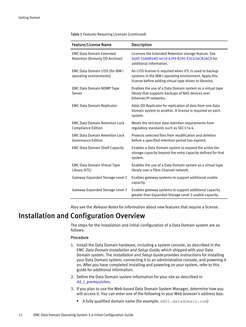
Table 1 Features Requiring Licenses (continued)
Feature/License Name Description- -EMC Data Domain ExtendedRetention (formerly DD Archiver)
Licenses the Extended Retention storage feature. See GUID-35AAB5AD-4619-42F9-B295-E3C634CB2ACD foradditional information.
EMC Data Domain I/OS (for IBM ioperating environments)
An I/OS license is required when VTL is used to backupsystems in the IBM i operating environment. Apply thislicense before adding virtual tape drives to libraries.
EMC Data Domain NDMP TapeServer
Enables the use of a Data Domain system as a virtual tapelibrary that supports backups of NAS devices overEthernet/IP networks.
EMC Data Domain Replicator Adds DD Replicator for replication of data from one DataDomain system to another. A license is required on eachsystem.
EMC Data Domain Retention LockCompliance Edition
Meets the strictest data retention requirements fromregulatory standards such as SEC17a-4.
EMC Data Domain Retention LockGovernance Edition
Protects selected files from modification and deletionbefore a specified retention period has expired.
EMC Data Domain Shelf Capacity Enables a Data Domain system to expand the active tierstorage capacity beyond the entry capacity defined for thatsystem.
EMC Data Domain Virtual TapeLibrary (VTL)
Enables the use of a Data Domain system as a virtual tapelibrary over a Fibre Channel network.
Gateway Expanded Storage Level 2 Enables gateway systems to support additional usablecapacity.
Gateway Expanded Storage Level 3 Enables gateway systems to support additional capacitygreater than Expanded Storage Level 2 usable capacity.
Also see the Release Notes for information about new features that require a license.
Installation and Configuration OverviewThe steps for the installation and initial configuration of a Data Domain system are asfollows:
Procedure
1. Install the Data Domain hardware, including a system console, as described in theEMC Data Domain Installation and Setup Guide, which shipped with your DataDomain system. The Installation and Setup Guide provides instructions for installingyour Data Domain system, connecting it to an administrative console, and powering iton. After you have completed installing and powering on your system, refer to thisguide for additional information.
2. Define the Data Domain system information for your site as described in dd_t_prerequisites.
3. If you plan to use the Web-based Data Domain System Manager, determine how youwill access it. You can enter one of the following in your Web browser's address box:
l A fully qualified domain name (for example, dd01.datadomain.com)
Getting Started
12 EMC Data Domain Operating System 5.4 Initial Configuration Guide

l A hostname (dd01)
l An IP address (10.5.50.5)
4. Perform the initial software configuration using one of the Configuration Wizards. Seethe Initial Configuration chapter.
5. If you changed the time, date, or time zone, reboot the Data Domain system.
6. Test the network connections.
7. If using the NFS protocol, mount directories for NFS-based backup servers andconfigure the backup software.
8. If using the CIFS protocol, when you connect from CIFS servers, set up user accountsand authentication on the CIFS server and set up backup software.
9. If using VTL, configure backup software for VTL data access and then set up the DataDomain system to use VTL (see the EMC Data Domain Operating SystemAdministration Guide).
10.If using EMC DD Boost, configure backup software for EMC DD Boost for OpenStoragedata access and the Data Domain system to use EMC DD Boost (see the EMC DataDomain Boost for OpenStorage Administration Guide).
11.Implement optional additional system configuration, such as giving access toadditional backup servers and adding users to the email list that reports systemproblems.
Getting Started
Installation and Configuration Overview 13

Getting Started
14 EMC Data Domain Operating System 5.4 Initial Configuration Guide

CHAPTER 2
Initial Configuration
This chapter covers the following topics:
u Logging In............................................................................................................. 16u Using the System Manager’s Configuration Wizard................................................ 16u Rebooting the Data Domain System...................................................................... 20u Using the CLI Configuration Wizard........................................................................21
Initial Configuration 15

Logging InAfter you first log into the Data Domain system following the instructions given in yourInstallation and Setup Guide, you can use the Data Domain System Manager Wizard forconfiguration. If you choose not to use it, then the CLI Configuration Wizard is run.
Note
You must assign an IP address to a Data Domain system in order for it to access theSystem Manager. See your Installation and Setup Guide for more information.
You can use either wizard to configure the DD OS for the first time. The wizards configurewhat is needed for a basic system setup.
u Data Domain System Manager WizardThe Data Domain System Manager is a browser-based graphical user interface,available through Ethernet connections. Its Configuration Wizard is similar in contentto the CLI-based Configuration Wizard, but provides a graphical interface withadditional configuration options.
u Command-Line Interface (CLI) WizardA command set that performs all system functions is available to users at theCommand-Line Interface (CLI). Commands configure system settings and providedisplays of system hardware status, feature configuration, and operation. Thecommand-line interface is available through a serial console when a keyboard andmonitor are directly attached to the Data Domain system, or remotely through anEthernet connection using SSH or Telnet.
After you configure the Data Domain system, you need to complete several post-configuration tasks, which are discussed in Post-Configuration Setup on page 27.
Note
u After the initial configuration, you can use either wizard to change or update theconfiguration. You must assign an IP address before you can use the SystemManager.
u When configuring a Data Domain system as part of a Replicator pair, follow the sameconfiguration steps as for a single system. If IPv6 addresses need to be configured forreplication, use the CLI because Data Domain System Manager does not support thesetting of IPv6 addresses.
Using the System Manager’s Configuration WizardOpen your Web browser and enter your Data Domain system’s IP address in the browser’saddress text box. Wait for the Data Domain System Manager to display the login screen.Enter your user name and password, and click Login.
The configuration modules are listed in the left pane. When one of the modules isselected, its details are shown in the main pane. You have the option of configuring ornot configuring any module. You must start at the first module Licenses, however, andeither configure or skip every module in order, ending with VTL Protocol.
Initial Configuration
16 EMC Data Domain Operating System 5.4 Initial Configuration Guide

Figure 1 Data Domain System Manager Configuration Wizard
Move through the modules using the Yes, No, Next, and Back buttons. Follow theinstructions on the screen. To complete a module, gather the necessary data to enter. See Obtain this Information Before You Start on page 10. Also see the next table.
You can use the Quit button to exit the wizard. For help information, click the questionmark in a dialog box.
After completing the Configuration Wizard:
u If you changed the date, time, or time zone, reboot the Data Domain system. See Rebooting the Data Domain System on page 20.
u Complete the post-configuration tasks discussed in Post-Configuration Setup on page27.
Note
You can return to this wizard to reconfigure any modules from within the Data DomainSystem Manager. Click the Maintenance > System tab and select Launch Configuration Wizardfrom the More Tasks menu. See the EMC Data Domain Operating System AdministrationGuide for more information.
Table 2 Data Domain System Manager Configuration Wizard Modules
Modules Information to be Entered- -Licenses Your purchased license keys.
Network l General: Either use DHCP or manually enter thehostname, domain name, and gateway IP address.
l Interfaces: Configure ports by using DHCP, or enteran IP address and netmask.
Note
Select DHCP's Enabled checkbox to enable theinterface. When the interface is disabled, itssettings cannot be changed.
l DNS information: DHCP or select an existing DNS IPaddress, or enter the DNS IP address.
Initial Configuration
Using the System Manager’s Configuration Wizard 17

Table 2 Data Domain System Manager Configuration Wizard Modules (continued)
Modules Information to be Entered- -File System (DD Extended Retentionand non-DD Extended Retentionversions)
For all file systems: Enable the file system after creation.For DD Extended Retention systems:l Select whether or not to create a file system that
supports Data Movement features and very largecapacity.
Note
Be sure that you want to create this kind of filesystem because it cannot be undone.
l Configure Enclosures shows the available storagefor the Retention Tier, formerly the Archive Tier.Select one or more available storage IDs and choose
Retention (or Archive) as the tier configuration. Click
the Add to Tier button, and click Next.
l Select the size of the first Retention (Archive) Unit.
l Select Enable the file system after creation.
System Settings Set up the following to ensure that autosupport (ASUPs)and alert emails from your system are sent to DataDomain.l Enter a password and email address for the
Administrator. The email address is the address ofthe administrator who is to receive system emails,such as alerts and autosupport. Select all emailoptions–to send alert notification, daily summaries,and autosupport.
l Mail Server. The name of the mail server used tosend outgoing alert and autosupport emails torecipients.
Recipients are subscribers to groups. A group nameddefault is created with the email address of twosubscribers: the administrator and [email protected].
Note
l Verify that the Send Alert Notification Emails to DataDomain is selected.
l Verify that the Send Vendor Support NotificationEmails to Data Domain is selected.
l System Location. For your information only.
Review the Summary page carefully. The default addressfor alerts and autosupport emails to Data Domain isautosupport-alert @autosupport.datadomain.com.
Initial Configuration
18 EMC Data Domain Operating System 5.4 Initial Configuration Guide

Table 2 Data Domain System Manager Configuration Wizard Modules (continued)
Modules Information to be Entered- -
The Vendor email is listed as Sending. The vendor emailaddress, which cannot be changed, is [email protected].
CIFS Protocol Workgroup: CIFS server name, if not using the default.Active Directory: Full realm name for the system, and aDomain Joining Credential user name and password.
Optionally, Organizational Unit name, if not using thedefault.
Share name and directory path.
Client name, if not using the default.
NFS Protocol Pathname for the export.NFS client server name to be added to /backup, if not
using an existing client. Select NFS options for the client.
Note
These clients receive the default permissions,which are read and write permissions, rootsquashing turned off, mapping of all user requeststo the anonymous UID/GID turned off, and secure.
EMC DD Boost Protocol l Either select an existing user, or add a new user byentering a user name and password.
l Select the new user’s roles. See “User Roles” onpage 27.
l Optionally, change the Storage Unit Name in the textbox.
l If EMC DD Boost is to be supported over FibreChannel transport, select the option to configure it.
l Create an Access Group. Enter a unique name.Duplicate access groups are not supported.
l Select one or more initiators. Optionally, replace theinitiator name by entering a new one.
Note
An initiator is a backup client that connects to thesystem for the purpose of reading and writing datausing the Fibre Channel protocol. A specificinitiator can support EMC DD Boost over FC or VTL,but not both.
The devices to be used are listed. They are available onall endpoints. An endpoint is the logical target on theData Domain system to which the initiator connects.
Initial Configuration
Using the System Manager’s Configuration Wizard 19

Table 2 Data Domain System Manager Configuration Wizard Modules (continued)
Modules Information to be Entered- -VTL Protocol l Library name, number of drives, drive model,
number of slots and CAPs, changer model name,starting barcode, and, optionally, tape capacity.
l Create an Access Group. Enter a unique name.Duplicate access groups are not supported.
l Select one or more initiators. Optionally, replace theinitiator name by entering a new one.
Note
An initiator is a backup client that connects to thesystem for the purpose of reading and writing datausing the Fibre Channel protocol. A specificinitiator can support EMC DD Boost over FC or VTL,but not both.
The devices (drives and changer) to be used are listed.These are available on all endpoints. An endpoint is thelogical target on the Data Domain system to which theinitiator connects.
User RolesA user can be assigned one of the following user roles:
u Admin role: Allows one to administer, that is, configure and monitor, the entire DataDomain system.
u User role: Allows one to monitor Data Domain systems and perform the fastcopyoperation.
u Security role: In addition to the user role privileges, allows one to set up security-officer configurations and manage other security-officer operators.
u Backup-operator role: In addition to the user role privileges, allows one to createsnapshots, import and export tapes to a VTL library and move tapes within a VTLlibrary.
u Data-access role: Intended for EMC DD Boost authentication, an operator with thisrole cannot monitor or configure a Data Domain system.
Rebooting the Data Domain SystemIf you changed the date, time, or time zone during the initial configuration, reboot theData Domain system. Otherwise, rebooting the system is not necessary.
Procedure
1. Select the Data Domain system to be rebooted in the System Manager's Navigationalpane.
2. Click Maintenance > System.
3. From the More Tasks menu select Reboot System.
4. Click OK at the Reboot System confirmation dialog box.
Initial Configuration
20 EMC Data Domain Operating System 5.4 Initial Configuration Guide

Using the CLI Configuration Wizard
About the CLIThe EMC DD OS Command Reference Guide provides information for using the commandsto accomplish specific administration tasks.
Each command also has an online help page that gives the complete command syntax.Help pages are available at the CLI using the help command.
Any Data Domain system command that accepts a list (such as a list of IP addresses)accepts entries separated by commas, by spaces, or both.
The Tab key can be used:
u to complete a command entry when that entry is unique. Tab completion is supportedfor all keywords. For example, entering syst<Tab> sh<Tab> st<Tab> displays thecommand system show stats.
u to show next available option (if no characters are entered before pressing the Tabkey)
u to show all the partial matched tokens or completes the entry if it is unique (whencharacters are entered before pressing the Tab key).
Note
After configuring the Data Domain system, reboot it only if you have changed the timezone. Use the system reboot command to shut down and reboot the system. Thiscommand automatically performs an orderly shutdown of file system processes.
Log Into the System Using the CLIAfter performing the initial configuration, you can access the system to work with the CLIusing one of these methods:
u From a serial console, use the communication settings 9600 baud, 8 data bits, noparity, and 1 stop bit.
u If your system includes a directly attached keyboard and monitor, log into the DataDomain system at the login prompt.
u From a remote machine over an Ethernet connection, use SSH to connect to the DataDomain system. Use the following command (with the hostname you chose for theData Domain system at initial configuration) and provide the sysadmin password.# ssh -l sysadmin hostname Data Domain OS 5.4.0.0-19899 Password:
Find Online Help for CommandsThere are several ways to find help for commands:
u To list Data Domain system commands, enter a question mark (?) or the commandhelp at the prompt.
u To list the options for a particular command, enter the command with no options atthe prompt.
Initial Configuration
Using the CLI Configuration Wizard 21

u To find a keyword used in a command option when you do not remember whichcommand to use, enter a question mark (?) or the help command followed by thekeyword.For example, the question mark followed by the keyword password displays all DataDomain system command options that include password. If the keyword matches acommand, such as net, then the command explanation appears.
u To display a detailed explanation of a particular command, enter the help commandfollowed by a command name.
u Use these help-related keyboard shortcuts:l Up and down arrow keys to move through a displayed command
l The q key to exit
l A slash character (/) and a pattern to search for lines of particular interest.Matches are highlighted.
Using the CLI Configuration WizardIf you do not choose to use the Data Domain System Manager Configuration Wizard forthe initial configuration, use the CLI Configuration Wizard.
To invoke the CLI Configuration Wizard after the initial setup, use the config setupcommand.
A description of each module follows.
LicensesAll licensed are installed at the factory, and a printed copy of the licenses is included withthe packing slip.
To activate licensed features installed on your system, enter a valid license key. Enter thelicense characters, including dashes, for each feature you have licensed. For example,enter ABCD-ABCD-ABCD-ABCDIf you have not licensed a category, make no entry.
Network
Configure the Network
Procedure
1. Enter the Data Domain system’s hostname, which is a fully qualified name thatincludes the domain name. For example, enter dd01.xyz.com.
2. Enter a domain name, such as corporation.com, for use by the DNS, or accept thedomain name that is part of the hostname. For example, enter xyz.com for thehostname dd01.xyz.com.
Configure Ethernet Interfaces (Ports)
Note
Settings are not reported if the interface is disabled.
Procedure
1. To enable the port, either use DHCP or assign a static IP address and netmask. If noaddress is to be assigned to the port, use the command: net config ifname up.
Initial Configuration
22 EMC Data Domain Operating System 5.4 Initial Configuration Guide

2. Select whether or not to use DHCP on the port.
If you are configuring the system using an Ethernet interface and you choose not touse DHCP, the Ethernet connection is lost when you complete the configuration.
If you have already set up DHCP for one or more Data Domain system Ethernetinterfaces, the IP address and netmask prompts display the values given to the DataDomain system from a DHCP server. Press Enter to accept these values.
3. If DHCP is not configured on a port, enter the IP address and the netmask for the port.
4. If any port is not using DHCP, specify an IP address for a default routing gateway.
5. If no network port is configured to use DHCP, or DHCP is not configured to provide theDNS servers, you can specify one, two, or three DNS servers to resolve hostnameswith IP addresses. Do one of the following:
l Enter the server name or names, separating items in the list with either a commaor a space.
l Choose to enter no servers by pressing the Enter key. In this case, use the nethosts command, which is described in the EMC Data Domain Operating SystemCommand Reference Guide, to inform the Data Domain system of IP addresses forhostnames.
6. Press Enter.
7. If you have additional Ethernet ports, set them up as described above.
Static Routing
Static routes should be set if multiple interfaces contain the same IPv6 subnets, and theconnections are being made to IPv6 addresses with this subnet. Normally, static routesare not needed with IPv4 addresses with the same subnet, such as for backups. There arecases in which static addresses may be required to allow connections to work, such asconnections from the Data Domain system to remote systems.
System Settings: Support and Alert EmailsYou must set up the following to ensure that support (ASUPs) and alert emails from yoursystem are sent to Data Domain.
Enter the following information:
u Admin Host(Required) Enter a hostname that will have administrative access to the Data Domainsystem. When you log into this host via the internet or intranet, you can view systemlogs. The hostname can be a fully qualified domain name, a simple hostname, or anIP address. The host is added to all administrative access lists and is set up as anNFS client for both the /backup and /ddvar directories.
u Admin Email(Required) Enter the email address or a group alias that is to receive email from theData Domain system. By default, the Data Domain system email list includes anaddress for the Data Domain Support group.
The system uses the email address as the sender of alert and autosupport emailmessages from this system, and as the recipient for these messages.
Initial Configuration
Using the CLI Configuration Wizard 23

Note
u The autosupport feature sends a daily report to Data Domain Support that showssystem identification information and consolidated output from Data Domain systemcommands and entries from various log files.
u Alerts occur whenever the system’s Restore Protection Manager discovers a problemwith software or a monitored hardware component. The alert command manages thealerts history file and who receives email notification for system alerts.
u For more information about autosupport and alerts, see the EMC DD OSAdministration Guide.
u System LocationEnter a physical location that identifies this system for use in autosupport emails. Forexample, enter Bldg4-rack10. The alerts and autosupport reports display thelocation.
u SMTP Mail ServerEnter the name of a local SMTP (mail) server that relays Data Domain system emails.If the server is an Exchange server, be sure that SMTP is enabled.
u Time ZoneThe system date has already been set. Changing the time zone requires that youreboot the Data Domain system.
Using the tables in Time Zones on page 45, determine your local time zone. Thedefault time zone for each Data Domain system is US/Pacific.
Note
Each time zone consists of two parts, which are separated with a slash (/).
u Network Time Service (NTP) ServersThe default is to enable NTP and to use multicast for NTP.
If DHCP is set up, do the following only if the DHCP server is not configured to providethe NTP servers:
To allow the Data Domain system to use one or more Network Time Service (NTP)servers to synchronize its clock, enter their IP addresses or server names, separatedby commas.
CIFS Protocol
Note
A single Data Domain system can receive backups from both CIFS and NFS clients only ifseparate directories or MTrees are used for each protocol. Do not mix CIFS and NFS datain the same directory.
The /backup directory is the destination directory on the Data Domain system forcompressed backup server data.
Initial Configuration
24 EMC Data Domain Operating System 5.4 Initial Configuration Guide

NFS Protocol
Note
A single Data Domain system can receive backups from both CIFS and NFS clients as longas separate directories are used for each. Do not mix CIFS and NFS data in the samedirectory.
The backup servers that can access the Data Domain system through NFS are the NFSclients of the system’s backup file system. The /backup directory is the destinationdirectory on the Data Domain system for compressed backup server data.
EMC DD Boost Protocol
For the initial setup, you are prompted to enter your EMC DD Boost user name, which canbe any EMC DD Boost user name. This name is used for EMC DD Boost authenticationonly. When prompted, save your settings.
After initial configuration, you typically create new storage units, display existing storageunits, and set storage unit options using the ddboost command options.
VTL Module
Follow these steps to configure VTL using the CLI Configuration Wizard's VTL module.Ranges for all of the values you are to enter are shown, such as 1 - 32 characters for theVTL library's name. For more information about configuring VTL, see the DD OSAdministration Guide.
Procedure
1. You are prompted to create a VTL library by entering an appropriate name.
2. Enter the library's emulation (changer) model: L180, RESTORER-L180, or TS3500.
Two other models, the i2000 and TS3200 are supported, but these models must beset up using either the DD System Manager or the command vtl group add .
3. As prompted, enter the number of slots and the number of CAPS (Cartridge AccessPorts).
4. Enter the drive model and the number of drives. The model options are IBM-LTO-1,IBM-LTO-2, or IBM-LTO-3.
The drives HP-LTO-3, HP-LTO-4, and IBM-LTO-4 are also supported, but you must addthem using either the DD System Manager or the command vtl drive add.
5. Define the tape parameters: barcode and capacity.
The eight-character barcode must start with six numeric or upper-case alphabeticcharacters (from the set {0-9, A-Z}) and end in a two-character code for the supportedtape type; for example, A99000LA. For tape capacity, enter0 to have the value derivedfrom the barcode.
Tape Code Tape Capacity in GiB Tape Type- - -L1 100 LT0-1
L2 200 LT0-2
L3 400 LT0-3
L4 800 LT0-4
Initial Configuration
Using the CLI Configuration Wizard 25

Tape Code Tape Capacity in GiB Tape Type- - -LA 50 LT0-1
LB 30 LT0-1
LC 10 LT0-1
6. Enter a descriptive name for a VTL access group.
VTL Access groups define logical groupings, which include initiators and targets. Anaccess group is logically equivalent to LUN masking.
7. Select yes at the next prompt to add VTL initiators to the previously created group.You must know the initiator's name to enter it; for example: pe2950_hba_zone_01.After the initial configuration assign an alias to an initiator using the vtl initiatorset aliascommand.
8. Continue to add initiators until all are included in the access group.
After adding initiators, the pending settings for the configured VTL are displayed.Pending SettingsLibrary name Knights Changer model TS3500 Slots 100 CAPs 1 Drive Model IBM-LTO-3 Drives 2 Barcode A99000LA Capacity 0 (if 0, will be derived from barcode)Group name RoundTable Initiators ------------------pe2950_hba_zone_01------------------
9. Review and save your settings.
Initial Configuration
26 EMC Data Domain Operating System 5.4 Initial Configuration Guide

CHAPTER 3
Post-Configuration Setup
After the initial configuration, perform these post-configuration tasks, as appropriate foryour installation. This chapter covers the following topics:
u Verify Support and Alert Emails............................................................................. 28u Security and Firewalls (NFS and CIFS Access).........................................................29u Verifying Network Connections..............................................................................29u About the /ddvar Directory (NFS and CIFS Clients)................................................. 29u Configuring the Data Domain System for Data Access............................................29
Post-Configuration Setup 27
Verify Support and Alert Emails
Note
Do not continue with the configuration until you verify that Data Domain can receivesupport and alert emails from your system. Do this whether you used the CLI or DataDomain System Manager Wizard for the initial setup.
Procedure
1. Assign an IP address to the Data Domain system using the CLI if you have not alreadydone so.
2. Open your Web browser and enter your Data Domain system’s IP address in thebrowser’s address text box. Wait for the Data Domain System Manager to display thelogin screen.
3. Enter your user name and password, and click Login.
4. Do one of the following:
l If you used the Data Domain System Manager Configuration Wizard, go to Step 5.
l If you used the CLI Configuration Wizard, do the following:
a. Click the Maintenance > System tab and select Launch Configuration Wizard from theMore Tasks menu.
b. Click through each of the modules by entering No or Next until you reach SystemSettings. Click Yes to configure system settings.
c. Verify the Administrator information is correct. Click Next.d. The Email information in the Email/Location section must be correct. Verify the
name of the mail server to be used to send outgoing Alert and Autosupport emailsto recipients.
e. Verify that Send Alert Notification Emails to Data Domain is selected.
f. Verify that the Send Vendor Support Notification Emails to Data Domain is selected. Theaddress, which cannot be changed, [email protected]. This notification status is enabled bydefault. The mail server location is for your information only.
g. Click Next and verify that the information you entered is correct in the Summary. Ifnot, go back to the sections that need changing and edit them.
h. After approving the updated Summary, click Submit.i. Click Next to exit each of the remaining modules. Exit the Configuration Wizard.
5. Go to Maintenance > Support > Autosupport. In the Vendor Support area, verify that theNotification Status for vendors is Enabled. You cannot change the email address.
6. Go to Status > Alerts > Notification. In the Alerts area, verify that default is selected as agroup. Verify that the Subscribers Email List contains the administrator [email protected] addresses.
Note
You can create other groups; add, modify, and delete email subscribers to groups;and set class attributes. Class attributes refer to the name of a class, such asHardware or File System. You set the severity of ranking, such as Warning or Critical,that is to trigger an alert for each class attribute. For more information, see the sectionthat discusses the Notification View in the EMC Data Domain Operating SystemAdministration Guide.
Post-Configuration Setup
28 EMC Data Domain Operating System 5.4 Initial Configuration Guide

Security and Firewalls (NFS and CIFS Access)The firewall should be configured so that only required and trusted clients have access tothe Data Domain system.
Please consult with your EMC technical support professional for instructions on settingup NFS and CIFS access through a firewall.
By default, anonymous users from known CIFS clients have access to the Data Domainsystem. For security purposes, change this option from disabled (the default) to enabled:# cifs option set restrict-anonymous enabled
Verifying Network ConnectionsTest both directions for each Data Domain interface on which traffic is expected forconnectivity.
Issue the ping command from a remote system to the hostname and issue the pingcommand from the host name to a remote system. If a port is on a private network or isdirectly attached, the remote system must be on the same private network, or directlyattached, for you to test it.
About the /ddvar Directory (NFS and CIFS Clients)The /ddvar directory contains Data Domain system core and log files. NFS and CIFSclients that need administrative access should to be able to access this directory.
The /ddvar directory has the following subdirectories:
u README
u certificates
u core, which is the default destination for core files created by the system.
u log, which is the destination for all system log files. As of DD OS 5.3, log messagesfrom CIFS subsystem are logged only in debug/cifs/cifs.log. Examine this logfile for CIFS issues.
u traces, which is the destination for execution traces used in debuggingperformance issues.
u releases, which is the default destination for operating system upgrades (the RPMfiles) that are downloaded from the Support Web site.
u snmp, which is the location of the SNMP (Simple Network Management Protocol) MIB(Management Information Base).
u support, which is the location for logs and autosupport files. Access this directoryto send autosupport files for Support, and for images for upgrading the Data Domainsystem. You can enable a CIFS share or NFS export to this location, as well as use FTP.
Create a CIFS Share to /ddvarSpecify clients allowed to access a Data Domain system's /ddvar directory:
# cifs add /ddvar client-list
Configuring the Data Domain System for Data AccessAfter completing the Configuration Wizard, you need to configure clients that access theData Domain system.
Post-Configuration Setup
Security and Firewalls (NFS and CIFS Access) 29

Procedure
1. Log into the Data Domain Support site at https://my.datadomain.
2. In the Navigation pane, click Documentation.
3. On the Documentation page, clink Integration Documentation.
4. Select the vendor for the client system’s operating system, such as Sun or Microsoft,and click OK.
5. Select the appropriate tuning document, such as the Solaris System Tuning or theCIFS Tuning Guide.
Post-Configuration Setup
30 EMC Data Domain Operating System 5.4 Initial Configuration Guide

CHAPTER 4
Additional Configuration
This chapter describes some additional configuration procedures that are performedonce the initial configuration with the Configuration Wizard is complete. This chaptercovers the following major topics:
u Changing the Timeout on CIFS Backup Servers...................................................... 32u Advanced Network Configuration.......................................................................... 32u Configuring SNMP on a Data Domain System.........................................................38u Configuring SOL for IPMI........................................................................................39u Configuring Encryption for Data at Rest..................................................................39u Optional Configuration Procedures........................................................................39
Additional Configuration 31
Changing the Timeout on CIFS Backup ServersIf internal activities on a Data Domain system take longer than the default CIFS timeout,the media server displays an error message that says the network name no longer exists.On all CIFS backup servers that use a Data Domain system, change the SESSTIMEOUTvalue from the default of 45 (seconds) to 300 (five minutes).
Change the Default Timeout ValueProcedure
1. Open the Registry Editor on the Windows machine. Go to Start > Run and type this inthe Open text box:
REGEDT32
2. Click OK.
3. Expand the My Computer node in the left pane.
4. Expand HKEY_LOCAL_MACHINE and continue to expand nodes in the directory tree untilyou reach the parameters menu from this path: SYSTEM > CurrentControlSet > Services >
lanmanworkstation > parameters.
5. If there is a SESSTIMEOUT key, it is located in the name list in the right pane. If thereis no such key, right-click within an empty space in the right pane, select New > Key,and name the new key SESSTIMEOUT, using all caps.
6. Double-click the SESSTIMEOUT key and set its value to 300.
Advanced Network ConfigurationThe following additional advanced network features can be configured on the DataDomain system:
u Ethernet FailoverYou can configure multiple network interfaces on a Data Domain system to functionas a single virtual interface. Should a network interface configured as part of a virtualinterface fail, network activity switches to another port. Ethernet failover providesimproved network stability.
u Link AggregationWith link aggregation, multiple physical Ethernet network ports can be used inparallel, which increases the link speed and also provides a reduced performancefailover capability over that of a single port. See the EMC DD OS Administration Guideand EMC DD OS Command Reference Guide for details.
u VLAN TaggingYou can set an interface on the Data Domain system to support multiple IEEE 802.1QVLANs, with an interface configured with a distinctive VLAN IP address. The switchthat connects to the interface must also be configured to send data from multipleVLANs to the Data Domain system, using the proper VLAN encapsulation, as specifiedby the 802.1Q protocol.
About the Ethernet Interface PortsThe Ethernet port- naming convention used for all Data Domain systems shipped prior toDD OS 4.9 included only a number for each port without regard to physical location ofthat port (for example, eth0 to eth5). Starting with new systems shipped with DD OS 4.9,the Ethernet Interface-naming scheme references both a PCI slot location and a specific
Additional Configuration
32 EMC Data Domain Operating System 5.4 Initial Configuration Guide

port on the NIC (for example, ethSlotPort, where Slot is the Ethernet card location in thesystem, and Port is the port, for example, a or b).
On EMC platforms, built-in Ethernet ports use slot M (Motherboard), and IO cardnumbering starts at zero.
To obtain information about the ports on your Data Domain system, use the commandnet show hardware.
Although Ethernet ports are typically configured in pairs, more than two ports can beconfigured as a virtual interface. Each physical Ethernet port, however, can be a part ofonly one virtual interface.
Create a Virtual InterfaceVirtual interfaces used for failover or link aggregation must be created from pairs that aresupported for the kind of interface you are creating.
u The maximum number of virtual interfaces is limited to the number of physical portson the system. Data Domain recommends a maximum of two virtual interfaces perData Domain system.
u In most cases, virtual interfaces should be created from identical physical interfaces,that is, all copper or all fiber, 1 GbE to 1 GbE, and NIC to NIC. Two exceptions are thatyou can mix 1 GbE optical to 1 GbE copper and a copper port on the motherboard to acopper port on a NIC.
u A VLAN interface cannot be created on a failover interface consisting of Chelsio 10GbE interfaces.
u All physical interfaces associated with a virtual interface must be on the same subnetand on the same LAN. Legacy cards must be on the same card for a 10 GbE virtualinterface. Network switches used by a virtual interface must be on the same subnet.
Follow these steps to create a virtual interface:
Procedure
1. Use the net createl command. Enter: #net create virtual vethx
where x is the variable for the virtual name (and this exact format is required). Thevariable consists of decimal or hexadecimal numbers (0-9 and aA-fF) that serve as anunique identifier for the virtual interface.
2. Use the net config command to assign the virtual interface (ifname) an IP addressand an optional netmask. Enter: # net config ifname ipaddr netmasknetmask
Note
DHCP is not supported for virtual interfaces, so the IP address must be assigned.
Configure FailoverTo configure failover:
Note
The on-board port ethMa is to be used only for maintenance and should not be bondedwith optional card ports.
Additional Configuration
Create a Virtual Interface 33

Procedure
1. Create a virtual interface and assign it an IP address. See Create a Virtual Interface onpage 33 for instructions.
2. Disable each of the Ethernet ports ifname that are to be part of the virtual interface byentering the following command, for each port:
# net disable ifnamewhere ifname is the port name. For example:
# net disable eth4a# net disable eth4b
3. Configure failover with the virtual interface name you created in step 1 and add thedesignated network interfaces. To assign one of the network interfaces as the primaryfailover interface, use the optional primary parameter.
Enter:
# net failover add virtual-ifname interfaces ifname-list [primaryifname]For example, to configure failover for the virtual interface named veth1 using thephysical ports eth4a and eth4b, and to assign eth4a as the primary port, enter:
# net failover add veth1 interfaces eth4a eth4b primary eth4aThis output displays:
Interfaces for veth1: eth4a, eth4b4. Assign an IP address and netmask to the new interface:
# net config ifname ipaddr netmask maskwhere ifname is the name of the interface (veth1 in this example) and mask is thecorresponding netmask.
5. Verify that the interface has been configured by entering:
# net failover showThe hardware address and configured interfaces (eth4a, eth4b) for the interfacenamed veth1 are displayed.
6. (Optional) To add another physical interface, such as eth5a, to the virtual interface,enter:
# net failover add veth1 interfaces eth5aThis output displays: Interfaces for veth1: eth4a,eth4b,eth5a
7. (Optional) To change the physical interface assigned as the primary failover interface,enter:
# net failover modify virtual-ifname primary {ifname | none}
Configure Link AggregationThe net aggregate command enables a virtual interface for link aggregation with thespecified physical interfaces using one of these aggregation modes. You need to specifyan aggregate mode first; there is no default aggregate mode.
DD OS 5.4 Limitation: Link aggregation is not supported for the DD2500's on-board 10GBase-T interfaces, which are ethMe and ethMf.
Additional Configuration
34 EMC Data Domain Operating System 5.4 Initial Configuration Guide

Note
Do not use the Akula NIC for customer data.
Select the mode that is compatible with the switch in use:
u roundrobinTransmits packets in sequential order from the first available link through the last inthe aggregated group.
u xor-L2Route transmit packets based on static balanced mode aggregation with an XOR hashof Layer 2 (inbound and outbound MAC addresses).
u xor-L2L3Route transmit packets based on static balanced mode aggregation with an XOR hashof Layer 2 (inbound and outbound MAC addresses) and Layer 3 (inbound andoutbound IP addresses).
u xor-L3L4Route transmit packets based on static balanced mode aggregation with an XOR hashof Layer 3 (inbound and outbound IP address) and Layer 4 (inbound and outboundport numbers).
u lacpA link aggregation mode based on the Link Aggregation Control Protocol (IEEE802.3ad).
Communicates with the other end to coordinate which links within the bond areavailable. When this mode is selected, both ends must be configured with lacp.
Some considerations for configuring link aggregation:
u Two or more Ethernet ports can be configured as interfaces for link aggregation.
u A physical port cannot already be configured for VLAN.
u All physical ports in the link aggregation group must be connected to the sameswitch, unless the switch can support the sharing of EtherChannel information.
To configure link aggregation:
Procedure
1. Create a virtual interface and assign it an IP address. See Create a Virtual Interface onpage 33 for instructions.
2. Disable each of the physical ports that you plan to use as aggregation interfaces.Enter: # net disable ifname
where ifname is the port name. For example, for eth2a and eth2b:
# net disable eth2a
# net disable eth2b
3. Create an aggregate virtual interface by specifying the physical ports and mode (themode must be specified the first time). Choose the mode that is compatible with therequirements of the switch to which the ports are directly attached. Enter: # netaggregate add virtual-ifname mode {roundrobin | xor-L2 |xor-L2} interfaces physical-ifname-list
For example, to enable link aggregation on virtual interface veth1 to physicalinterfaces eth1a and eth2a in mode xor-L2, enter: # net aggregate add veth1 modexor-l2 interfaces eth2a eth3a
4. Assign an IP address and netmask to the new interface using this command: # netconfig ifname ipaddr netmask mask
Additional Configuration
Configure Link Aggregation 35

where ifname is the name of the interface, which is veth1 in this example, ipaddr is theinterface’s IP address, and mask is the netmask.
5. To verify that the interface has been created, enter: # net aggregate show
The output displays the name of the virtual interface, its hardware address,aggregation mode, and the ports that comprise the virtual interface.
Configure VLAN TaggingTo configure VLAN tagging:
Procedure
1. Configure the switch port that connects to the interface that is to receive and sendVLAN traffic from the Data Domain interface. See the switch documentation for detailson the configuration.
2. On the Data Domain system, enable the interface that you plan to use as the VLANinterface, such as eth5b, by entering: # net config eth5b up
3. Create the VLAN interface using either a physical port or a configured virtual port (tocreate the virtual port, see Create a Virtual Interface on page 33. The range for vlan-idis between 1 and 4094 inclusive: #net create interface {physical-ifname | virtual-ifname}vlan vlan-id
For example, to create a VLAN interface on a physical interface eth5b, enter: # netcreate interface eth5b vlan 1
A VLAN interface named eth5b.1 is created.
4. Assign an IP address and netmask to the new interface using this command: # netconfig ifname ipaddr netmask mask
where ifname is the name of the interface, which is eth5b.1 in this example, ipaddr is theinterface’s IP address, and mask is the corresponding netmask.
Note
DHCP cannot be used to assign an IP address to a VLAN.
5. To verify that the interface has been created, enter: #net show settings .Thefollowing information displays:
Port Enabled DHCP IP Address Netmask Type Additional Setting- - - - - -eth5b1 yes yes 192.168.8.175* 255.255.252.0* n/a
After you finish
For more information, see the EMC Data Domain Operating System Command ReferenceGuide.
Additional Physical or Virtual Interface ConfigurationYou can set the maximum transfer unit (MTU) size and configure duplex line usage andspeed.
Specify the MTUYou can set the MTU size for a physical or virtual interface, or a vlan interface if the MTUsize is less than or equal to the underlining base interface MTU value. Supported
Additional Configuration
36 EMC Data Domain Operating System 5.4 Initial Configuration Guide

maximum transfer unit size values range from 1500 to 9000. For 100 Base-T and gigabitnetworks, 1500 is the default.
Note
Although 9000 is the maximum size, to be backward compatible, the DD OS accepts upto 9014, but sets the value to 9000 when it is greater than 9000 and less than or equal to9014.
Use the default option to return the setting to the default value.
Note
All of your network components need to support the size that you set. Incorrectly settingMTU affects system performance.
The minimum size for MTU is 350, except when the IP address is set to IPv6. In this casethe minimum MTU is 1280.
Enter:
# net config ifname mtu {size | default}where ifname is the name of the interface.
Configure Duplex Line Use and SpeedTo configure the duplex line use and speed for an interface, use one of these threeoptions:
u Set the duplex line use for an interface to either half- or full-duplex and set its portline speed for 10, 100, or 1000 Base-T (gigabit).
u Have the network interface card automatically negotiate these settings for aninterface.
Note
The following restrictions apply:u Duplex line use and auto-negotiate do not apply to 10 GbE cards.
u A line speed of 1000 must have a full-duplex setting.
To set an interface’s duplex line use, enter: # net config ifname duplex {full|half} speed{10 | 100 | 1000}
For example, to set veth1 to duplex with a speed of 100 Base-T, enter: # net configveth1 duplex half speed 100
Set Auto-Negotiate for an InterfaceProcedure
1. Enter: # net config ifname autonegFor example, to set auto-negotiate for interface eth1a, enter:
# net config eth1a autoneg
Routing Tables and GatewaysAfter you have configured the interface for failover, aggregation, or VLAN tagging,assigned an IP address, set the netmask, and enabled the interface, the interface is
Additional Configuration
Routing Tables and Gateways 37

automatically added to the routing table. The new entry should appear when you enter: #route show tableThe virtual interface is in the same subnet as the physical interface; therefore, the defaultgateway does not change.
Configuring SNMP on a Data Domain SystemFrom an SNMP perspective, a Data Domain system is a read-only device with thisexception—a remote machine can set the SNMP location, contact, and system name on aData Domain system. To configure community strings, hosts, and other SNMP variableson the Data Domain system, use the snmp command.
With one or more trap hosts defined, a Data Domain system takes the additional action ofsending alert messages as SNMP traps, even when the SNMP agent is disabled.
Display Configuration CommandsTo view the current SNMP configuration, enter: # snmp show config
Add a Community StringAs an administrator, enter one of these commands that enable access to a Data Domainsystem, either to add read/write (rw) or read-only (ro) permission:
# snmp add rw-community community-string-list{hostshost-list}
#snmp add ro-community community-string-list{hostshost-list}
For example, to add a community string of private with read/write permissions, enter: #snmp add rw-community private hosts host.datadomain.com.
Enable SNMPBy default, SNMP is disabled on the Data Domain system. To enable SNMP, at least oneread or read/write community string must be set before the snmp enable command isgiven.
As an administrator, enter:
# snmp enableThe default port that is opened when SNMP is enabled is port 161. Traps are sent to port162.
Set the System LocationAs an administrator, enter:
# snmp set sysLocation location
This command sets the system location as used in the SNMP MIB II system variablesysLocation. For example:
snmp set sysLocation bldg3-rm222
Set a System ContactAs an administrator, enter:
# snmp set sysContaccontact
This command sets the system contact as used in the SNMP MIB II system variablesysContac. For example:
#snmp set sysContac bob-smith
Additional Configuration
38 EMC Data Domain Operating System 5.4 Initial Configuration Guide

Note
The SNMP sysContact variable is not the same as that set using the config set admin-email command. If the SNMP variables are not set with the snmp commands, the variablesdefault to the system values given as part of the config set commands.
Add a Trap HostAs an administrator, enter:
# snmp add trap-host host-name-list[:port[version {v2c | v3 }] [communitycommunity user |user }]
where host may be a hostname or an IP address. By default, port 162 is assigned, but youcan specify another port. For example, to add a trap host admin12, enter:
#snmp add trap-host admin12 version v2c community publicThis command adds a trap host to the list of machines that receive SNMP traps generatedby the Data Domain system. With one or more trap hosts defined, alert messages are alsosent as traps, even when the SNMP agent is disabled.
Configuring SOL for IPMIYou can use the Intelligent Platform Management Interface (IPMI) to power up, powerdown, or power cycle a Data Domain system in a remote location from a host DataDomain system, if both systems support this standard. The Serial-Over-LAN (SOL) featureof IPMI is used to view the serial output of a remote system’s boot sequence. Instructionsfor configuring SOL for IPMI are included in the EMC Data Domain Operating SystemCommand Reference Guide.
Configuring Encryption for Data at RestThe optional Encryption for Data at Rest feature encrypts all incoming data before writingit to the Data Domain system’s physical storage media. The data is physically stored in anencrypted manner and cannot be accessed on the existing Data Domain system or in anyother environment without first decrypting it.
Note
Optimally, the Encryption for Data at Rest feature should be configured when setting upyour system. Data is encrypted only after the feature’s configuration is complete, that is,any pre-existing data will not be encrypted.
To learn more about how the Encryption at Rest feature works, and to view configurationand management procedures, see the EMC Data Domain Operating SystemAdministration Guide.
Optional Configuration ProceduresYou can perform the following tasks now or later. See the EMC Data Domain OperatingSystem Administration Guide for more information.
u Add users
u Enable FTP, FTPS, SCP, and Telnet for data access
u Add remote hosts that can use FTP or Telnet
u Add email addresses to receive system reports
Additional Configuration
Configuring SOL for IPMI 39

Additional Configuration
40 EMC Data Domain Operating System 5.4 Initial Configuration Guide

CHAPTER 5
Adding Expansion Shelves
This chapter covers the following topics:
u Overview............................................................................................................... 42u Add Enclosure Disks to the Volume....................................................................... 42u Disks Labeled Unknown Instead of Spare.............................................................. 43u Verify Shelf Installation......................................................................................... 43
Adding Expansion Shelves 41

OverviewInstall the new expansion shelf as described in the Data Domain Expansion ShelfHardware Guide for your shelf model or models. The procedure described here, whichadds shelves to the volume and creates RAID groups, applies only to adding a newexpansion shelf to the active tier of a Data Domain system. For adding shelves to asystem with the Extended Retention feature, see the appropriate Data Domain ExpansionShelf Hardware Guide and the EMC Data Domain Extended Retention AdministrationGuide.
The Data Domain system recognizes all data storage (system and attached shelves) aspart of a single volume.
Mixing SAS and SATA disks within an enclosure is not supported, and mixing SAS andSATA disk enclosures on the same SAS chain is not supported.
DD Platform SAS Support SATA Support- - -DD2500 No Yes
DD4500 Headswap Only Yes
All Other Models Yes No
CAUTION
Do not remove a shelf that has been added unless you are prepared to lose all data inthe volume. If a shelf is disconnected, the volume’s file system is immediately disabled.To re-enable it, reconnect the shelf or transfer the shelf disks to another shelf chassisand connect the new chassis. If the data on a shelf is not available to the volume, thevolume cannot be recovered. Unless the same disks are in the original shelf or in a newshelf chassis, the DD OS must be re-installed as directed by your contracted serviceprovider or Data Domain’s Support site (https://my.datadomain.com/).
Add Enclosure Disks to the VolumeProcedure
1. Use the following command: # storage add [tier {active | archive}]{enclosure enclosure-id | dev disk-id [spindle-group 1-16 | diskenclosure-id disk-id} where enclosure-id is always 2 for the first added shelf and 3for the second.
Note
The EMC Data Domain controller always has the enclosure-id of 1 (one).
2. When prompted, enter your sysadmin password.
3. (Optional) Add disks in another enclosure at this time using the above-mentionedstorage add command.
4. Display the RAID groups for each shelf by entering: storage show all
Note
EMC ES30 shelves have one spare disk. ES20 shelves have two spare disks. The restof the disks should report that they are available or spare disks.
Adding Expansion Shelves
42 EMC Data Domain Operating System 5.4 Initial Configuration Guide

Disks Labeled Unknown Instead of SpareProcedure
1. Enter the disk unfail command for each unknown disk. For example, if the two disks2.15 and 2.16 are labeled unknown, enter commands like these:
# disk unfail 2.15
# disk unfail 2.16
2. Verify the new state of the file system and disks by entering: filesys status
3. After a shelf has been added to the file system, you can view the total size, amount ofspace used, and available space for each file system resource, such as data,metadata, and index, by entering: filesys show space.
Verify Shelf InstallationProcedure
1. After installing the new shelves, check the status of the SAS HBA cards by entering:disk port show summary
The output shows the port for each SAS connection, such as 3a and 4a, and theonline status, which is offline. After the shelves have been connected, the samecommand also displays the connected enclosure IDs for each port, such as 2 and 3.The status changes to online.
2. Verify that the Data Domain system recognizes the shelves by entering: enclosureshow summary
This command shows each recognized enclosure ID, Data Domain system modelnumber, serial number, and slot capacity, as well as state of the enclosure andinformation about the shelf's manufacturer.
Adding Expansion Shelves
Disks Labeled Unknown Instead of Spare 43

Adding Expansion Shelves
44 EMC Data Domain Operating System 5.4 Initial Configuration Guide

APPENDIX A
Time Zones
This chapter covers the following topics:
u Time Zones Overview.............................................................................................46u Africa.................................................................................................................... 46u America.................................................................................................................46u Antarctica..............................................................................................................47u Asia.......................................................................................................................47u Atlantic................................................................................................................. 48u Australia............................................................................................................... 48u Brazil.................................................................................................................... 48u Canada................................................................................................................. 48u Chile..................................................................................................................... 48u Etc.........................................................................................................................48u Europe.................................................................................................................. 49u GMT...................................................................................................................... 49u Indian (Indian Ocean)............................................................................................49u Mexico.................................................................................................................. 49u Miscellaneous.......................................................................................................49u Pacific................................................................................................................... 50u System V...............................................................................................................50u US (United States).................................................................................................50u Aliases.................................................................................................................. 50
Time Zones 45

Time Zones OverviewTime zone are used when you initially configure your system to establish the location.
Locate your time zone using the following tables. A time zone usually consists of twoentries separated by a slash (/). The first entry is usually a continent, nation, or regionsuch as Africa, the Pacific, or the United States. The second entry is usually the city withinthat area that is closest to you. There are also aliases for time zones and miscellaneousentries, such as GMT, Cuba, and Japan that are single entries.
Examples of time zones include:
u GMT+5
u Stockholm
u Pacific
u EasterIsland
u Japan
AfricaAbidjan Accra Addis_Ababa Algiers Asmera
Bamako Bangui Banjul Bissau Blantyre
Brazzaville Bujumbura Cairo Casablanca Ceuta
Conakry Dakar Dar_es_Salaam Djibouti Douala
El_Aaiun Freetown Gaborone Harare Johannesburg
Kampala Khartoum Kigali Kinshasa Lagos
Libreville Lome Luanda Lubumbashi Lusaka
Malabo Maputo Maseru Mbabane Mogadishu
Monrovia Nairobi Ndjamena Niamey Nouakchott
Ouagadougou Porto-Novo Sao_Tome Timbuktu Tripoli
Tunis Windhoek
AmericaAdak Anchorage Anguilla Antigua Araguaina
Aruba Asuncion Atka Barbados Belem
Belize Boa_Vista Bogota Boise Buenos_Aires
Cambridge_Bay Cancun Caracas Catamarca Cayenne
Cayman Chicago Chihuahua Cordoba Costa_Rica
Cuiaba Curacao Danmarkshavn Dawson Dawson_Creek
Denver Detroit Dominica Edmonton Eirunepe
El_Salvador Ensenada Fortaleza Fort_Wayne Glace_Bay
Godthab Goose_Bay Grand_Turk Grenada Guadeloupe
Guatemala Guayaquil Guyana Halifax Havana
Time Zones
46 EMC Data Domain Operating System 5.4 Initial Configuration Guide

Hermosillo Indiana/Indianapolis
Indiana/Knox Indiana/Marengo
Indianapolis
Indiana/Vevay Inuvik Iqaluit Jamaica Jujuy
Juneau Kentucky/Louisville Kentucky/Monticello Knox_IN La_Paz
Lima Los_Angeles Louisville Maceio Managua
Manaus Martinique Mazatlan Mendoza Menominee
Merida Mexico_City Miquelon Monterrey Montevideo
Montreal Montserrat Nassau New_York Nipigon
Nome Noronha North_Dakota/Center
Panama Pangnirtung
Paramaribo Phoenix Port-au-Prince Porto_Acre Port_of_Spain
Porto_Velho Puerto_Rico Rainy_River Rankin_Inlet Recife
Regina Rio_Branco Rosario Santiago Santo_Domingo
Sao_Paulo Scoresbysund Shiprock St_Johns St_Kitts
St_Lucia St_Thomas St_Vincent Swift_Current Tegucigalpa
Thule Thunder_Bay Tijuana Tortola Vancouver
Virgin Whitehorse Winnipeg Yakutat Yellowknife
AntarcticaCasey Davis DumontDUrville Mawson McMurdo
Palmer South_Pole Syowa Vostok Arctic/Longyearbyen
AsiaAden Almaty Amman Anadyr Aqtau
Aqtobe Ashgabat Ashkhabad Baghdad Bahrain
Baku Bangkok Beijing Beirut Bishkek
Brunei Calcutta Choibalsan Chongqing Chungking
Colombo Dacca Damascus Dhaka Dili
Dubai Dushanbe Gaza Harbin Hong_Kong
Hovd Irkutsk Istanbul Jakarta Jayapura
Jerusalem Kabul Kamchatka Karachi Kashgar
Katmandu Krasnoyarsk Kuala_Lumpur Kuching Kuwait
Macao Macau Magadan Makassar Manila
Muscat Nicosia Novosibirsk Omsk Oral
Phnom_Penh Pontianak Pyongyang Qatar Qyzylorda
Rangoon Riyadh Riyadh87 Riyadh88 Riyadh89
Time Zones
Antarctica 47

Saigon Sakhalin Samarkand Seoul Shanghai
Singapore Taipei Tashkent Tbilisi Tehran
Tel_Aviv Thimbu Thimphu Tokyo Ujung_Pandang
Ulaanbaatar Ulan_Bator Urumqi Vientiane Vladivostok
Yakutsk Yekaterinburg Yerevan
AtlanticAzores Bermuda Canary Cape_Verde Faeroe
Jan_Mayen Madeira Reykjavik South_Georgia St_Helena
Stanley
AustraliaACT Adelaide Brisbane Broken_Hill Canberra
Darwin Hobart LHI Lindeman Lord Howe
Melbourne NSW North Perth Queensland
South Sydney Tasmania Victoria West
Yancowinna
BrazilAcre DeNoronha East West
CanadaAtlantic Central East-Saskatchewan Eastern
Mountain Newfoundland Pacific Saskatchewan
Yukon
ChileContinental EasterIsland
EtcGMT GMT+0 GMT+1 GMT+2 GMT+3
GMT+4 GMT+5 GMT+6 GMT+7 GMT+8
GMT+9 GMT+10 GMT+11 GMT+12 GMT0
GMT-0 GMT-1 GMT-2 GMT-3 GMT-4
GMT-5 GMT-6 GMT-7 GMT-8 GMT-9
GMT-10 GMT-11 GMT-12 GMT-13 GMT-14
Time Zones
48 EMC Data Domain Operating System 5.4 Initial Configuration Guide

Greenwich UCT Universal UTC Zulu
EuropeAmsterdam Andorra Athens Belfast Belgrade
Berlin Bratislava Brussels Bucharest Budapest
Chisinau Copenhagen Dublin Gibraltar Helsinki
Istanbul Kaliningrad Kiev Lisbon Ljubljana
London Luxembourg Madrid Malta Minsk
Monaco Moscow Nicosia Oslo Paris
Prague Riga Rome Samara San_Marino
Sarajevo Simferopol Skopje Sofia Stockholm
Tallinn Tirane Tiraspol Uzhgorod Vaduz
Vatican Vienna Vilnius Warsaw Zagreb
Zaporozhye Zurich
GMTGMT GMT+1 GMT+2 GMT+3 GMT+4
GMT+5 GMT+6 GMT+7 GMT+8 GMT+9
GMT+10 GMT+11 GMT+12 GMT+13 GMT-1
GMT-2 GMT-3 GMT-4 GMT-5 GMT-6
GMT-7 GMT-8 GMT-9 GMT-10 GMT-11
GMT-12
Indian (Indian Ocean)Antananarivo Chagos Christmas Cocos Comoro
Kerguelen Mahe Maldives Mauritius Mayotte
Reunion
MexicoBajaNorte BajaSur General
MiscellaneousArctic/Longyearbyen
CET CST6CDT Cuba EET
Egypt Eire EST EST5EDT Factory
GB GB-Eire Greenwich Hongkong HST
Time Zones
Europe 49

Iceland Iran Israel Jamaica Japan
Kwajalein Libya MET MST MST7MDT
Navajo NZ NZ-CHAT Poland Portugal
PRC PST8PDT ROC ROK Singapore
Turkey UCT Universal UTC WET
W-SU Zulu
PacificApia Auckland Chatham Easter Efate
Enderbury Fakaofo Fiji Funafuti Galapagos
Gambier Guadalcanal Guam Honolulu Johnston
Kiritimati Kosrae Kwajalein Majuro Marquesas
Midway Nauru Niue Norfolk Noumea
Pago_Pago Palau Pitcairn Ponape Port_Moresby
Rarotonga Saipan Samoa Tahiti Tarawa
Tongatapu Truk Wake Wallis Yap
System VAST4 AST4ADT CST6 CST6CDT EST5
EST5EDT HST10 MST7 MST7MDT PST8
PST8PDT YST9 YST9YDT
US (United States)Alaska Aleutian Arizona Central East-Indiana
Eastern Hawaii Indiana-Starke Michigan Mountain
Pacific Samoa
AliasesGMT=Greenwich, UCT, UTC, Universal, Zulu CET=MET (Middle European Time)Eastern=Jamaica Mountain=Navajo
Time Zones
50 EMC Data Domain Operating System 5.4 Initial Configuration Guide

APPENDIX B
EMC Data Domain System Security Configuration
This appendix provides an overview of the security configuration settings available for theData Domain system, including secure deployment and usage settings, and the securemaintenance and physical security controls that ensure secure operation.
The following topics are covered:
u Data Domain System Security Overview.................................................................52u Security Configuration Settings .............................................................................52u Secure Maintenance: Data Migration.....................................................................66u Physical Security Controls..................................................................................... 67
EMC Data Domain System Security Configuration 51

Data Domain System Security OverviewThe Data Domain system is an appliance that runs the DD OS embedded operatingsystem. Additional software or agents cannot be installed or executed within a DataDomain appliance. This restriction ensures control and consistency of DD OS releasesand provides additional security.
Data Domain systems are viewed as a purpose-built appliance with restricted access totheir internal operation; any tampering voids the warranty. EMC incorporates newreleases of embedded open-source modules into DD OS versions as appropriate.
Hosts and backup applications interface with the Data Domain systems through one ormore of the standard native server interface protocols: CIFS/NFS, NDMP, VTL, or EMC DataDomain Boost. You can mount a network share on the Data Domain directly (server direct)via one of the standard network file sharing protocols: CIFS or NFS.
Access control and user authentication to the Data Domain system is controlled either bylocal users, NIS environments, or within a Microsoft Active Directory Domainenvironment.
The following Data Domain native protocols and software options depend on or enablesecurity attributes of the Data Domain system. See the EMC Data Domain OperatingSystem Administration Guide for more information.
u Supported Native Ingest protocols. Data Domain systems support simultaneousaccess via common network access protocols, allowing both backup servers andapplication servers to send data to the Data Domain system. Servers can attach andtransfer files and backup images over one or more of these protocols: CIFS, NFS, EMCData Domain Boost, NDMP, and VTL over Fibre channel. Because data moved overthese protocols are transported “in the clear” and no encryption is supported for datatransfers over these protocols, user authentication and access control to the relatednetwork ports is of critical importance.
u EMC Data Domain Replicator software provides automated, policy-based, network-efficient replication for disaster recovery, remote office data protection, and multi-sitetape consolidation. DD Replicator software asynchronously replicates only thecompressed, deduplicated data over the WAN during the backup process, makingnetwork-based replication fast, reliable, and cost-effective. For environments that donot leverage a VPN for secure connections between sites, DD Replicator software cansecurely encapsulate its replication payload over SSL with AES 256 bit encryption forsecure transmission over the wire.
u EMC Data Domain Encryption software is an administratively enabled option set usingthe CLI or Data Domain System Manager. It protects backup and archive data storedon Data Domain systems with data encryption that is performed inline before the datais written to disk. Encrypting data at rest satisfies internal governance rules andcompliance regulations and protects against the reading of customer data onindividual disks or disk shelves removed from the system due to theft.
u DD Retention Lock prevents specified files from being overwritten, modified, ordeleted for a user-defined retention period of up to 70 years, or until January 19,2038, if you are using NFS, because of protocol constraints.
Security Configuration SettingsThe following security setting categories are discussed:
u Access control settings, which are under administrative control, limit access by endusers and external product components.
u Log settings relate to the logging of events.
EMC Data Domain System Security Configuration
52 EMC Data Domain Operating System 5.4 Initial Configuration Guide

u Communication security settings relate to security for the product networkcommunications.
u Data security settings ensure protection of the data associated with the product.
u Secure serviceability settings are available to ensure control of service operationsperformed on the products by EMC or its service partners.
u Security alert system settings relate to sending security alerts and notifications forsecurity-related events.
u Additional security considerations: EMC Data Domain Retention Lock, dual sign-onrequirements, and the secure system clock.
Access Control SettingsThe Data Domain operating environment provides secure administrativeistration by oneof the following methods. Either method allows locally defined users, NetworkInformation Service (NIS) users, and Microsoft Active directory domain users.
u Data Domain System Manager via HTTPS. The Data Domain system can use its self-signed identity certificate to establish a trusted connection to manage the DataDomain system over SSL.
u SSH for CLI. The administrator enters a controlled shell environment, where individualCLI commands are executed to manage the Data Domain system.
Administrative system access can be either Local or Remote.
u Local AccessCLI via serial or over the IP local access is available for authorized administrators whoare on the same subnet and have proper login credentials (username and password).For access, the user is prompted for the username and password; once validated theuser enters the default controlled user CLI shell environment.
Note
Policies should be put in place for users to log out after the session is over.No other access method (such as remote dial-in or a physical RS-232 connection) tothe appliance is available.
u Remote AccessCLI and Web-based System Manager remote access are available for authorizedadministrators with proper login credentials (username and password). Remote userswith network access and authorization can remotely administer the Data Domainsystems over the network.
Note
By default only secure shell (SSH) and secure browsing (HTTPS) is enabled on theData Domain system. SSH also supports password-less login.EMC recommends configuring session timeout values in Data Domain SystemManager to ensure users are automatically logged out of the system after the sessionis over. The timeout needs to be longer than the maximum configuration time. Forexample, the worst case for DHCP configuration is 90 seconds. Session timeoutshould be no less than five minutes.
Data Domain systems feature security protocols to control access to the data residing onthe system. Data is not readily viewable from anywhere except a host that has beengranted access. The following main access control methods are available in a DataDomain system:
EMC Data Domain System Security Configuration
Access Control Settings 53

u Host-based access listsAdministrator access is required to configure the Data Domain appliance and adjustwhich physical hosts can view an exported mount point. Those with administrativeaccess can update the access list with a server’s hostname or IP address. A DataDomain system can use DNS for name resolution; for greater protection,administrators can hard code entries in the hosts file to control hosts/port resolution.
u File PermissionsFiles created on the Data Domain system are “owned” by the creator. For example,backup software typically writes files as a particular user, so that user would own allfiles that the backup software created on the system. Explicit Windows permissions(ACLs) must be set, however, to prevent users from viewing files created by others.
l Microsoft CIFSFor every file or folder created through CIFS, the following attributes are created:
– Owner SID
– Group SID
– DACL (Discretionary ACL – Permissions)
– SACL (System ACL – Auditing Information)
– DOS Attributes such as READONLY, HIDDEN, SYSTEM & ARCHIVE
In addition, folders and files map Unix UID/GID/MODE from Windows Owner-SID/Group-SID/DACL. The DACL is inherited from its parent. If the parent directory doesnot have DACL (created though NFS/non-CIFS), then a default ACL is assigned. Thedefault gives the owner full control and gives others read permission. Accesscontrol is managed through the standard Microsoft MMC on any client withpermissions to do so.
l Linux NFSFiles and folders created through the remaining ingest protocols use the POSIX.1eACL standard. Every object is associated with three sets of permissions thatdefine access for the owner, the owning group, and for others. Each set maycontain Read (r), Write (w), and Execute (x) permissions. This scheme isimplemented using only nine bits for each object. In addition to these nine bits,the Set User Id, Set Group Id, and Sticky bits are used for a number of specialcases. Access control is managed through a standard Linux client or Data Domainsystem CLI administration environment with permissions to do so.
u Microsoft Active Directory ServicesData Domain systems can utilize Microsoft Active Directory pass-throughauthentication for the users/servers. Admins can enable certain domains and groupsof users to access files stored on the Data Domain system.
u NIS Directory ServicesData Domain systems can utilize NIS Directory Authentication for the users in UNIX/LINUX environments. Administrators can enable specific hosts and users to accessfiles stored on the Data Domain system.
The combination of a host-based access list along with local users or domaindirectory services allows the administrator to control which users and servers havepermissions to view data on a Data Domain system.
u Separate NFS and CIFS sharesAdmins can easily create shares on the Data Domain file system. Using the nativeaccess control methods helps to define more granular share/directory/file-levelaccess control over certain data on the Data Domain system. For example, whensetting up a shared system for multiple customers, administrators can have a NFS orCIFS share created for each specific customer on the same Data Domain system andspecify access controls for each customer/share.
EMC Data Domain System Security Configuration
54 EMC Data Domain Operating System 5.4 Initial Configuration Guide

The following access control settings are described:
u Default Accounts
u Authentication Configuration
u User Authorization
u Component Access Control
u Component Authentication
u Component Authorization
Default Accountsu sysadmin is the default user account on the DD system.
During the initial configuration the administrator who logs in as sysadmin isprompted to change the password. The sysadmin account cannot be deleted.
u The default password is the Data Domain system’s serial number or service tagnumber.
Authentication ConfigurationFor instructions on changing default account passwords and deleting accounts that areno longer in use, see Managing Data Domain Systems in the EMC Data Domain OperatingSystem Administration Guide.
Data Domain System Integration into Microsoft’s Active Directory (AD)
With the latest version of the DD OS installed, follow this procedure.
Procedure
1. Determine authentication mode and verify connectivity.
a. Determine the authentication mode configuration on the Data Domain system byentering: # cifs show config
If the mode is Workgroup or Domain, the system is not configured for AD.
If the mode is Active-Directory, the system is using Active Directory Authentication(Windows 2000 and later). Whether or not the system is properly communicatingwith AD, however, is not verified.
b. To verify connectivity to AD, look up a non-administrator AD user using the CIFStroubleshooting command. Enter: # cifs troubleshooting user user name
If the user cannot be found, the Data Domain system is not communicating withAD.
If details of the AD user are listed, such as user and group and their IDs, the DataDomain system is successfully communicating with AD.
2. Prepare the Data Domain system to join AD if the system is not configured or notcommunicating with AD.
a. If the authentication mode is currently set to Domain or Active Directory Mode,configure the Data Domain system for Workgroup Mode by entering:
# cifs set authentication workgroup workgroup
b. Verify DNS settings on the Data Domain system. Enter:
# net show dnsc. To change the DNS server, enter:
# net set dns dns server ip
EMC Data Domain System Security Configuration
Access Control Settings 55

d. Test IP connectivity from the Data Domain system to the DNS server.
# net ping dns server ip count 3
e. Confirm the AD domain. Access a DOS prompt on a Windows computer (server orclient does not matter). At the Windows DOS prompt, enter:
set
USERDNSDOMAIN= is the domain name that is used when setting the domainname on the Data Domain system.
f. Confirm the Data Domain system domain name by entering:
# net show domainname
If the domain name is not correct, enter:
# net set domainname domain name
g. Confirm that the domain name responds to the command net ping.
# net ping domain name count 3
If net ping does not respond, make sure the correct DNS server has beenspecified.
h. Confirm the Data Domain system’s host name.
# net show hostname
If the host name is not correct, set it to the correct name:
# net set hostname host name
3. (Optional) If you have a server that is running the Network Time Service (NTP) you canchoose to configure NTP at this time. See the EMC Data Domain Operating SystemAdministration Guide.
4. Verify the Data Domain system’s system clock and compare the time with the ADdomain controller. Enter:
# date
To modify the time, enter:
# system set date MMDDhhmm[[CC]YY]
Compare the Data Domain system’s system clock with the AD domain controller. Theymust be within 5 minutes of each other.
5. Join the Data Domain system to AD.
To successfully join the Data Domain system to AD, the Windows administratoraccount must have the correct permissions.
Verify that administrator account password does not contain spaces, right and leftsquare brackets ([,]), or the dollar sign ($).
Enter:
# cifs set authentication active-directoryrealm domain controller ip address, *
For example:
# cifs set authentication active-directory olympus.local 123.456.78.90, *
6. To verify connectivity to AD, look up a (non-administrator) AD, enter:
# cifs troubleshooting user user name
If the details of the AD user are listed, the Data Domain system is successfullycommunicating with AD.
EMC Data Domain System Security Configuration
56 EMC Data Domain Operating System 5.4 Initial Configuration Guide

7. To verify that the Data Domain system host is listed in AD, check that the Data Domainsystem host is listed in the computer container in the Active Directory (Active DirectoryUsers and Computers page).
8. Ensure backups are working. Run a backup to the Data Domain system and verify thatit finishes without errors.
Actions Not Requiring AuthenticationMost, but not all show commands and viewing of statistics do not require authentication.
User AuthorizationUser authorization settings control rights or permissions that are granted to a user toaccess a resource managed by the Data Domain system.
A Data Domain system supports five classes of users:
u User. This is the class for standard users who have access to a limited number ofoperations and commands. The user class can view configuration information only.
u Admin. This is the class for administrators who have access to all Data Domainsystem operations and commands. Administrators cannot view the actual user datastored on the Data Domain system directly, but can copy the data off the unit to anexternal client location.
u Sysadmin. This is the default user account on a Data Domain system. During theinitial configuration the sysadmin is prompted to change the password. This accountcannot be deleted, but the password can be changed after the administrator haslogged in.
u Security Officer. This is the class for enabling/disabling a specific set of securityfunctions. In DD OS 5.0 or later, the security officer class is one of the two usersrequired for DD Encryption lock/unlock, and for changing the encryption passphrase.Security officer is also required for Retention Lock compliance.
u Backup Operator. This class, which is available with DD OS 5.2 or later, has a pre-defined set of controls to manage specific backup and recovery related tasks thatinclude:l Add and delete SSH public keys for password-less log-in (mostly used for
automated scripting)
l Add, delete, reset and view CLI command aliases
l View configuration and settings related to alerts, autosupport, NIS, CIFS, DDBoost, storage, file system, cleaning, network, MTrees, NFS, NTP, Replication,Route, SNMP, snapshot, system, users, logs, and so forth.
l Perform a fast copy of data from a source to destination path
l Perform the syncing of all modified files
l Wait for replication to complete on the destination system
l Create snapshots for MTrees
l Change password for a user
l Import/export and move tapes between elements in a Virtual Tape Library
l View all VTL configuration.
System PasswordsPassword management is an integral part of DD OS. Managed by the admin user, apassword can be set for individual users with a variety of controls:
EMC Data Domain System Security Configuration
Access Control Settings 57

u Minimum Days Between Change: The minimum number of days between passwordchanges that you allow a user. The default is 0.
u Maximum Days Between Change: The maximum number of days between passwordchanges that you allow a user. The default is 99999.
u Warn Days Before Expire: The number of days to warn the users before their passwordexpires. The default is 7.
u Disable Days After Expire: The number of days after a password expires to disable theuser account. The default is Never.
u Disable Account on the Following Date: The option to select an account and enter adate (mm/dd/yyyy) when you want to disable it. The default is no date.
For uniform password management across the enterprise, a default password policy canbe changed and applied to all newly created passwords with the default policy set.
Local UsersThe local users reside on the Data Domain system, and are either created through CLI orthrough DD System Manager. UIDs are assigned in the range of 500-10,000 to localusers. When an access request comes in through one of the network interfaces, the DDOS does a look-up on the user first to determine if it already has the user in its local userlist.
New local users can be added or deleted, by the Data Domain administrator, for loginaccess to a Data Domain system. The new user can either be a regular user with limitedfunctionality or an admin user to perform administrative tasks. Backup Operator andSecurity Officer users, are also local users.
Note
All user account information is stored in the root file system and not accessible viacontrolled CLI or GUI.
Domain UsersIf the Data Domain system does not find the user in its local file, it will make an externalrequest on the network to the configured Domain Directory Services Server to resolve andacknowledge the requesting user’s access rights and permissions. This is known as pass-through authentication. The Data Domain Operating System supports two types ofexternal domain pass-through authentication:
Microsoft Active Directory Services: A protocol for managing users, host names, andaccess rights among systems on a network, primarily for Microsoft environments.
NIS (Network Information Service): A rudimentary, but functional directory serviceprotocol for distributing system configuration data supporting users on a network,primarily for UNIX/LINUX environments.
Component AuthenticationFor instructions about how to configure authentication of remote components, seeManaging Network Connections in the EMC DD OS Administration Guide.
Component AuthorizationFor instructions about how to configure the product to restrict access to remotecomponents or systems, such as IP filtering, see Managing Network Connections in theEMC Data Domain Operating System Administration Guide.
Log SettingsA log is a chronological record of system activities that is sufficient to enable thereconstruction and examination of the sequence of environments and activities
EMC Data Domain System Security Configuration
58 EMC Data Domain Operating System 5.4 Initial Configuration Guide

surrounding or leading to an operation, procedure, or event in a security-relevanttransaction from inception to final results.
All Data Domain system logs (system, space, errors, access related) are stored on the rootfile system partition, and not accessible directly except through these services:
u Logs can be sent to a remote syslog server for long-term archiving via FTP or SCP(authorized support personnel only).
u Logs can be accessed via successful login via the CLI or the System Manager.
The Data Domain system log file entries contain messages from the alerts feature,autosupport reports, and general system messages. The log directory is /ddvar/log.
For more information, see Managing Log Files in the EMC Data Domain Operating SystemAdministration Guide.
Communication Security SettingsCommunication security settings enable the establishment of secure communicationchannels between the product components as well as between product components andexternal systems or components.
Port UsageThe System Manager uses HTTP port 80 and HTTPS port 443. If your Data Domain systemis behind a firewall, to reach the systems, you might need to enable port 80 if using HTTP,or port 443 if using HTTPS. The port numbers can be easily changed if securityrequirements dictate.
Traps are sent out through port 162.
When adding a DD System to the Data Domain System Manager: If a port is configured,enter a Custom Port instead of the default port 3009.
Administration/Support ProtocolsThe Data Domain system supports several services and protocols for administration.Telnet is used to access the controller. The CLI environment is disabled by default. Youcan enable it from the Web-based Data Domain System Manager’s System Settings >Access Management page (Port 23).
These services and protocols include:
u HTTP/HTTPS is used to access the Data Domain System Manager. Open either Port 80or secure Port 443. HTTPS uses the Data Domain system’s internally generated signedcertificate to establish a trust between the client and the Data Domain system’s Webbrowser. SSH is used to access the Data Domain CLI (Port 22). You can enable it fromthe Data Domain System Manager via the System Settings > Access Managementpage.
u FTP, FTPS and SCP are used to download logs, autosupport files and support bundles,and can be used to upload DD OS Upgrade RPM files.
FTP is an insecure protocol that allows passwords to pass unencrypted over thenetwork.
FTPS or SCP are recommended as secure file transfer methods of administrative files.
u Secure Copy (SCP) is used by Support to securely copy or move internal system filessuch as system logs in and out of the Data Domain system. SCP is available to anyadmin user and uses the same port as SSH (Port 22). It is enabled by default.
EMC Data Domain System Security Configuration
Communication Security Settings 59

u FTP is used for moving files to and from the Data Domain system for maintenancepurposes only (Port 20/21). It can be enabled via the System Settings > AccessManagement page.
Note
As of DD OS 5.3, SFTP is supported.
u Secure Copy (SCP) is used by Support to securely copy or move internal system filessuch as system logs in and out of the Data Domain system. SCP is available to anyadmin user and uses the same port as SSH (Port 22). It is enabled by default.
Data Transfer ProtocolsProtocols that can be enabled on a Data Domain system to ingest data from a server andto restore data to a server include:
u NFS (v3 over TCP only) – UNIX/LINUX file sharing protocol
u CIFS (SMB 1 only) - Microsoft network file sharing protocol
u EMC Data Domain Boost – A client-side plug-in with a proprietary protocol over IPnetworks. As of DD OS 5.3, EMC DD Boost is also available over Fibre Channelnetworks. It is designed to optimize and accelerate backup software and productapplication interaction with Data Domain systems. By distributing parts of thededuplication process to the backup server or application client, EMC DD Boostspeeds up aggregate backup throughput on Data Domain systems up to 50 percent,while reducing load on LANs.
u Data Domain Virtual Tape Library –Tape emulation over Fibre Channel
u NDMP - an open protocol for transporting data between NAS devices and a DataDomain system
Other protocols that can be enabled on a Data Domain system include:
u NTP – Network Time Protocol - An industry standard protocol for time synchronization.
u SNMP – An industry standard protocol for sending and monitoring MIB data.
u SSL – An industry standard protocol used to encapsulate the payload while data is inflight for secure replication between Data Domain systems.
Data Domain TCP and UDP Ports
Table 3 Data Domain System Inbound Communication Ports
Port Service Description
TCP 21 FTP Port is used only if FTP is enabled. Run adminaccessshow on the Data Domain system to determine if it is
enabled.
TCP 22 SSH & SCP Port is used only if SSH is enabled. Run adminaccessshow on the Data Domain system to determine if it is
enabled. SCP is enabled as default
TCP 23 Telnet Port is used only if Telnet is enabled. Run adminaccessshow on the Data Domain system to determine if it is
enabled.
EMC Data Domain System Security Configuration
60 EMC Data Domain Operating System 5.4 Initial Configuration Guide

Table 3 Data Domain System Inbound Communication Ports (continued)
TCP 80 HTTP Port is used only if HTTP is enabled. Run adminaccessshow on the Data Domain system to determine if it is
enabled.
TCP 111 EMC DD Boost /NFS (portmapper)
Used to assign a random port for the mountd serviceused by EMC DD Boost and NFS. Mountd service portcan be statically assigned.
TCP 123 NTP Port is used only if NTP is enabled on the Data Domainsystem. Run ntp status to determine if it is enabled.
UDP 137 CIFS (NetBIOSName Service)
Port used by CIFS for NetBIOS name resolution.
UDP 138 CIFS (NetBIOSDatagram Service)
Port used by CIFS for NetBIOS Datagram Service.
TCP 139 CIFS (NetBIOSSession Service)
Port used by CIFS for session information.
TCP 161 SNMP Port is used only if SNMP is enabled. Run snmp statusto determine if it is enabled.
TCP 443 HTTPS Port is used only if HTTPS is enabled. Runadminaccess show on the Data Domain system to
determine if it is enabled.
TCP 445 CIFS (Microsoft-DS) Main port used by CIFS for data transfer.
TCP 2049 EMC DD Boost /NFS
Main port used by NFS. Can be modified via the nfsreset server-port command. (This command is SE
mode, which means that it can be issued only by aService Engineer.)
TCP 2051 Replication Port is used only if replication is configured on the DataDomain system. Run replication show config to
determine if it is configured. This port can be modifiedvia the replication modify command.
* NFS (mountd) Can be hardcoded via command nfs reset mountd-port(This command is SE mode, which means that it
can be issued only by a Service Engineer.)
TCP 3009 DDMC Port This port is used only if the Data Domain system isbeing managed by the Data Domain ManagementCenter.
Table 4 Outbound Communication Traffic Ports
Port Service Description
TCP 25 SMTP Used by the Data Domain system to send emailautosupports and alerts.
TCP 80 HTTP Used by Data Domain system for uploading log filesto Data Domain Support via the support uploadcommand.
EMC Data Domain System Security Configuration
Communication Security Settings 61

Table 4 Outbound Communication Traffic Ports (continued)
TCP 123 NTP Used by the Data Domain system to synchronize toa time server.
TCP 160 SNMP Used by the Data Domain system to send SNMPtraps to SNMP host. Use snmp show trap-hoststo see destination hosts and snmp status to
display service status.
TCP 514 Syslog Used by the Data Domain system to send syslogmessages, if enabled. Use log host show to
display destination hosts and service status.
TCP 2051 Replication Used by Data Domain system only if replication isconfigured. Enter replication show config to
determine if it is configured.
TCP 3009 DDMC Port This port is used only if the Data Domain system isbeing managed by the Data Domain ManagementCenter.
Network EncryptionThe CA and Host certificates need to be compatible with the RSA DPM Key Manager. Youcan request these certificates from third-party certificates authorities, or create themusing appropriate SSL utility tools. For information about encryption certificates and keymanagers, seeManaging Encryption of Data at Rest in the EMC Data Domain OperatingSystem Administration Guide.
For SSL usage with the Data Domain system, see Manage FTP Access and Monitoring DataDomain System in the EMC Data Domain Operating System Administration Guide.
DD Replicator supports encryption of data-in-flight by using standard Secure Socket Layer(SSL). For information about encrypting replicated data, see Working with Replication inthe EMC Data Domain Operating System Administration Guide.
Externally Signed Certificate of Authority (CA)
If the Data Domain system uses the RSA Data Protection Manager external encryption keymanager, it requires a PKCS12 host certificate and an external Certificate of Authority inPEM (public certificate) format in order to establish a trusted connection between the RSAData Protection Manager Server and each Data Domain system that it manages.
The certificate signing requires PKCS10 format. The public certificate key can have eitherPKCS12 (public plus a private key) or PEM (public) format. The host certificate PEM formatis used only with the CSR (Certificate Signing request) feature. Only one external host orCA certificate is allowed for the Data Domain system. HTTPS requires only the hostcertificate.
If the host certificate has the server/client X509V3v extension, it is used for HTTPS/RSADPM Key Manager. If the host certificate has no extension, or both client and serverextensions, it is used for both RSA DPM Key Manager and HTTPS.
DD OS 5.3 and later support the importation of the host certificate in PKCS12 format. Ifthere is a CSR on the system, you can import the host certificate in PEM format after theCSR is signed by a Certificate Authority.
EMC Data Domain System Security Configuration
62 EMC Data Domain Operating System 5.4 Initial Configuration Guide

Note
u The system passphrase is required to import the certificate.
u The system can use only one external host certificate.
Uploading Certificates
You can upload either PEM (public key) or PKCS12 (a public plus a private key) to theData Domain system via secure FTP in the /ddvar/certificates directory.
Follow these steps:
Procedure
1. From your local machine, copy the host PKCS12 certificate to the Data Domain systemby entering:
$ scp Host PKCS12 file admin@Data Domain System:/ddvar/certificates
2. From the Data Domain system, import the host certificate and specify the filename.
# adminaccess certificate import host file Host PKCS12 file
3. When prompted to provide the password to decrypt the PKCS12 file, enter thepassword.
If the procedure is successful, you are informed that the certificate has beenimported.
Self-Signed Certificates
DD OS 5.1 and DD OS 5.2 use the MD5 Message-Digest Algorithm in the self-signedcertificate generation process. DD OS 5.3 and later use the SHA1 Message-Digestalgorithm for the self-signed certificate.
DDOS 5.3 and later support the generation of CSRs in PKCS10 format. The certificatesigning request is available in this location:
/ddvar/certificates/CertificateSigningRequest.csrYou can use either SCP, FTP, or FTPS to obtain the CSR from the Data Domain system.
The command to generate the certificate signing request is:
# adminaccess certificate generate cert-signing-request
Provide the following:
u Private Key strength: The enumeration values allowed are 1024 bit, 2048 bit, or 4096bit. The default value is 2048 bit.
u Country: The default value is US. This abbreviation cannot exceed two characters. Nospecial characters are allowed.
u State: The default value is California. The maximum entry is 128 characters long.
u City: The default value is Santa Clara. The maximum entry is 128 characters long.
u Organization Name: The default value is My Company Ltd. The maximum entry is 64characters long.
u Organization Unit: The default value is an empty string. The maximum entry is 64characters long.
u Common Name: The default value is system hostname. The maximum entry is 64characters long.
EMC Data Domain System Security Configuration
Communication Security Settings 63
Data Security SettingsData security settings enable definition of controls to prevent data permanently stored bythe product to be disclosed in an unauthorized manner.
Encryption OverviewThere are two types of encryption offered with Data Domain systems:
u Encryption of data-at-rest via the Data Domain Encryption software option.
u Encryption of data-in-flight via Data Domain Replicator software, used for replicatingdata between sites over the WAN.
DD Encryption: Encryption of Data-at-RestEncryption of data-at-rest protects user data if the Data Domain system is lost or stolenand eliminates accidental exposure if a failed drive needs to be replaced. When the filesystem is intentionally locked, an intruder who circumvents network security controls andgains access to the Data Domain system will be unable to read the file system without theproper administrative control, passphrase, and cryptographic key. DD Encryptionsoftware is completely transparent to the backup or archive application.
DD Encryption provides inline encryption, which means as data is being ingested, thestream is deduplicated, compressed and encrypted using a encryption key before beingwritten to the RAID group. Data Domain Encryption software uses RSA BSAFE libraries,which are FIPS 140-2 validated.
The Data Domain administrator can select a 128-bit or 256-bit Advanced EncryptionStandard (AES) algorithm for encrypting all data within the system. One of two ciphermodes, Cipher Block Chaining mode (CBC) or Galois/Counter mode (GCM), can beselected to best fit security and performance requirements. In addition, the systemleverages a user-defined passphrase to encrypt that key before it is stored in multiplelocations on disk. The system encryption key cannot be changed and is not, in any way,accessible to a user. Without the passphrase, the Data Domain file system cannot beunlocked, thus data is not accessible.
With DD OS 4.9/5.0/5.1, when DD Encryption software is enabled, the system randomlygenerates a single, static system-wide cryptographic strength encryption key.
With DD OS 5.2 or later,an environment that requires encryption keys to be changed on aperiodic basis to meet security and compliance regulation can have its encryption keyexternally managed by RSA DPM. DPM can manage the life cycle of the encryption key foreach Data Domain system. Policies to rotate the encryption key on a periodic basis canbe centrally configured using RSA DPM. Keys can also be deleted, expired, or marked ascompromised when there is a possibility of a data breach. To further ensure that theencryption keys are safeguarded, a copy of the keys is stored in a second RSA DPMserver. In addition, RSA DPM provides audit logs for key state changes that are necessaryto prove compliance.
DD OS 5.3 introduces the Data Domain internal Embedded Key Manager. By default, theData Domain Embedded Key Manager is in effect after you restart the file system unlessyou configure the RSA DMP Key Manager.
DD Replicator - Encryption of Data-in-FlightEncryption of data-in-flight encrypts data being transferred via DD Replicator software. Ituses OpenSSL AES 256-bit encryption to encapsulate the replicated data over the wire.The encryption encapsulation layer is immediately removed as soon as it lands on thedestination Data Domain system. Data within the payload can also be encrypted via DataDomain's encryption software.
EMC Data Domain System Security Configuration
64 EMC Data Domain Operating System 5.4 Initial Configuration Guide
Data ErasureThe filesys destroy command deletes all data in the Data Domain file system. Youcan also destroy the file system using the Data Domain System Manager. For moreinformation on commands, see the EMC Data Domain Operating System CommandReference Guide. See the EMC Data Domain Operating System Administration Guide forinformation about using the System Manager.
System sanitization was designed to remove all traces of deleted files and restore thesystem to the state prior to the file's existence. The primary use of the sanitizecommand is to resolve Classified Message Incidents (CMIs) that occur when classifieddata is copied inadvertently onto a non-secure system. System sanitization is typicallyrequired in government installations.
Note
The DD data erasure is not compliant with DoD requirements. For DoD compliance, EMCoffers a service Model Number: PS- BAS-DDDE. Information can be found at http://powerlink.emc.com/km/appmanager/km/secureDesktop?_nfpb=true&_pageLabel=query1&internalId=0b0140668060f2d1&_irrt=true
Secure Serviceability Settings
Note
See the section on user roles in the EMC Data Domain Operating System AdministrationGuide. Your contracted support provider has access to settings that are not available tothe general administrator.
EMC Secure Remote SupportEMC Secure Remote Support (ESRS) is an IP-based automated connect home and remotesupport solution. ESRS creates both a unified architecture and a common point of accessfor remote support activities performed on your EMC product. The ESRS IP Solution doesthe following:
u Provides continuous monitoring, diagnosis, and repair of minor EMC hardwareissues.
u Uses the most advanced encryption, authentication, audit, and authorization forultra-high security remote support.
u Addresses compliance with corporate and governmental regulations by providinglogs of all access events.
u Provides easy integration and configuration with your storage management networkand firewalls.
u Provides maximum information infrastructure protection. IP-based sessions enablefast information transfer and resolution.
u Consolidates remote support for your EMC information with the ESRS Gateway Client.
u Provides failover protection.
u Provides remote access to your disaster recovery site and makes recovery fromunplanned events seamless.
u Protects information in motion or at rest. AES256 encryption during informationtransfer protects your information.
u Reduces costs and data center clutter and accelerates time to resolution. Theelimination of modem/phone line costs translates to lower costs.
EMC Data Domain System Security Configuration
Secure Serviceability Settings 65

EMC Secure Remote Support technical documentation is available on the EMC onlinesupport site.
Security Alert System SettingsSee the EMC Data Domain Operating System Administration Guide for information abouthow to manage alerts.
EMC Data Domain Retention Lock SoftwareEMC Data Domain Retention Lock software provides immutable file locking and securedata retention capabilities for customers that meet both corporate governance andcompliance standards, such as SEC 17a-4(f). DD Retention Lock provides the capabilityfor administrators to apply retention policies at an individual file level. This softwareenables customers to leverage their existing Data Domain appliances for backup andarchive data. DD Retention Lock ensures that archive data is retained long-term with dataintegrity and secure data retention. DD Retention Lock Governance edition and DDRetention Lock Compliance edition can coexist on the same Data Domain system toenable different retention periods for different classes of archive data. DD Retention Locksoftware is compatible with industry-standard, NAS-based (CIFS, NFS) Write-Once-Read-Many (WORM) protocols and is qualified with leading archive applications such as EMCSourceOne, EMC DiskXtender, and Symantec Enterprise Vault.
Dual Sign-On RequirementsWhen DD Retention Lock Compliance is enabled on a Data Domain system, additionaladministrative security is provided in the form of “dual” sign-on. This requires a sign-onby the system administrator as well as a sign-on by a second authorized authority(referred to as “Security Officer”). The “dual” sign-on mechanism of the DD RetentionLock Compliance edition acts as a safeguard against any actions that could potentiallycompromise the integrity of record files before the expiration of the retention period.
Secure System ClockOne of the primary requirements of regulatory compliance standards is time-basedretention in which records are preserved exclusively in a non-rewritable, non-erasableformat. To meet this requirement a Data Domain system ensures that any undesiredchanges to the system clock on the Data Domain controller cannot be executed.
Secure Maintenance: Data MigrationData migration offers Data Domain customers the ability to transfer data from one DataDomain system to another for maintenance, which is primarily used for retiring an oldersystem or for upgrading to a newer Data Domain system.
The migration function is available for administrators only and is usually executed over aLAN. Administrators must use the command line interface. The migration commandcopies all data, metadata, replication contexts (configurations,) and user- configurationinformation from one Data Domain system to another. Data migration considerationsfollow:
u Data migration assumes the Data Domain systems are properly configured for thenetwork, with both systems having properly configured security access.
u All data under/backup will be migrated to MTrees that have the same names on boththe source and destination systems after the migration.
EMC Data Domain System Security Configuration
66 EMC Data Domain Operating System 5.4 Initial Configuration Guide

u After migrating replication contexts, the migrated contexts remain on the migrationsource. The administrator needs to disable replication on the migration source.
u Backup operations to the migration source should be paused during migration.
u The migration destination does not need a replication license for migration alone.
u The migration destination must have a capacity that is the same size as or larger thanthe used space on the migration source.
u The migration destination must have an empty file system.
u Migration to a system with Extended Retention software option is supported only ifthe source system also has the Extended Retention software option.
Physical Security ControlsPhysical security controls enable the protection of resources against unauthorizedphysical access and physical tampering.
The ES20, DD660, and DD690 have a disk-drive locking mechanism that prevents theremoval of a disk drive without the appropriate tool, which is a T10 Torx screwdriver. Thebezel on the ES30 has a lock and key that prevents access to the drives.
The DD880, DD140, DD160, DD610, DD620, DD630 have no physical access controls.The DD4200, DD4500, DD7200, and the DD990 have E330-style bezels, although there isno key lock on the DD990.
For more information, see the following related EMC documentation for your product: EMCData Domain Expansion Shelf Hardware Guide, the EMC Data Domain Hardware Guide, ordisk FRU replacement guides.
EMC Data Domain System Security Configuration
Physical Security Controls 67

EMC Data Domain System Security Configuration
68 EMC Data Domain Operating System 5.4 Initial Configuration Guide