initial design and optimization of turbomachinery with ... · pdf fileinitial design and...
TRANSCRIPT
www.cfturbo.com© CFturbo® Software & Engineering GmbH page 1/21
Initial Design and Optimization of Turbomachinerywith CFturbo® and optiSLang®
Sebastian Stübing, Gero Kreuzfeld, Ralph-Peter Müller (CFturbo)Stefan Marth, Michael Schimmelpfennig (Dynardo)
www.cfturbo.com© CFturbo® Software & Engineering GmbH page 2/21
Contents
1. Introduction• CFturbo ® : Company • CFturbo ® : Software Tool
2. Optimization Workflow
3. Results• Proceeding• Optimized design
4. Summary / Outlook • Existing workflow for single point turbomachinery optimization• Further developments - workflow for multi-purpose optimization

www.cfturbo.com© CFturbo® Software & Engineering GmbH page 3/21
CFturbo® - Business Areas
CFturbo® Software & Engineering GmbH
Engineering CAD & Prototyping
• Turbomachinery Conceptual Design
• CFD/FEA Simulation
• Optimization
• 3D-CAD Modeling
• Prototyping
• Testing, Validation
CFturbo® Software
• Turbomachinery Design Software
• Automated Workflows
Introduction
www.cfturbo.com© CFturbo® Software & Engineering GmbH page 4/21
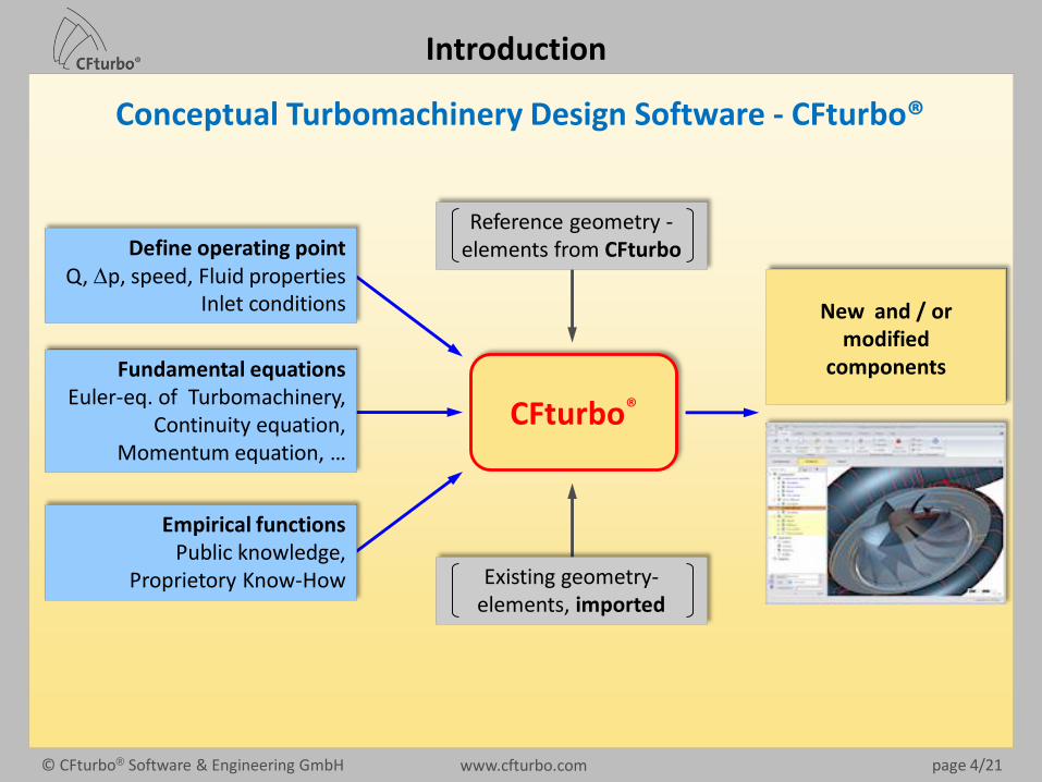
Conceptual Turbomachinery Design Software - CFturbo®
CFturbo®
Fundamental equationsEuler-eq. of Turbomachinery,
Continuity equation, Momentum equation, …
Empirical functionsPublic knowledge,
Proprietory Know-How Existing geometry-elements, imported
Reference geometry -elements from CFturboDefine operating point
Q, Dp, speed, Fluid propertiesInlet conditions New and / or
modifiedcomponents
Introduction

www.cfturbo.com© CFturbo® Software & Engineering GmbH page 5/21
Typical development process for Turbomachinery components
ConceptualDesign
CFturbo®
MeshingANSA, AutoGrid, ICEM, Pointwise, TurboGrid, …
3D-CADCATIA, SolidWorks, UG NX,
ProE, BladeModeler, …
ProductionRe-computation/optimizationinteractively or automated
CFD/FEA SimulationSTAR CCM+, ANSYS-CFX,FINE/Turbo, PumpLinx, …
ExperimentsPrototyping,
Validation
Design Simulation & Validation Product
Introduction
www.cfturbo.com© CFturbo® Software & Engineering GmbH page 6/21
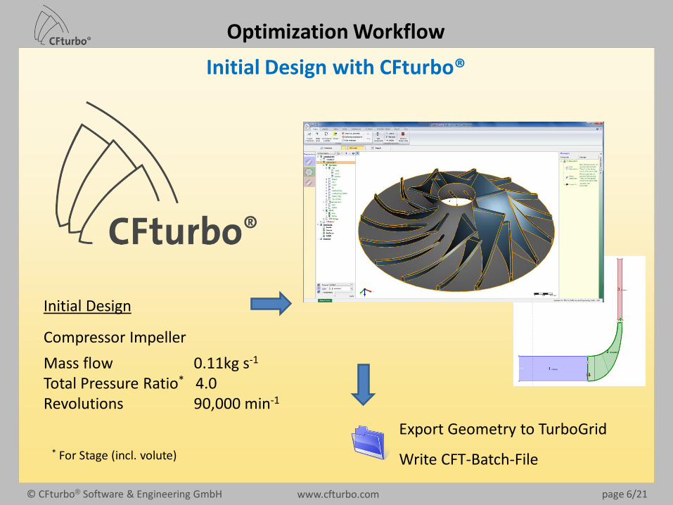
Initial Design with CFturbo®
Export Geometry to TurboGrid
Write CFT-Batch-File
Initial Design
Compressor Impeller
Mass flow 0.11kg s-1
Total Pressure Ratio* 4.0Revolutions 90,000 min-1
* For Stage (incl. volute)
Optimization Workflow

www.cfturbo.com© CFturbo® Software & Engineering GmbH page 7/21
ANSYS Workbench – Meshing
Optimization Workflow
Number of nodes: 176394Number of elements: 155167
Inlet- / Outlet-Stator designed in CFturbo®
Also possible: Design Modeller Component

www.cfturbo.com© CFturbo® Software & Engineering GmbH page 8/21
ANSYS Workbench – CFD Simulation
Optimization Workflow
ptot = 1bar
𝑚 =0.11 𝑘𝑔 𝑠
𝑁𝑠𝑒𝑔𝑚𝑒𝑛𝑡𝑠
periodic walls
Steady state simulation, frozen rotor
ResultsTotal Pressure Ratio PImpeller efficiency hPower consumption Pi
www.cfturbo.com© CFturbo® Software & Engineering GmbH page 9/21
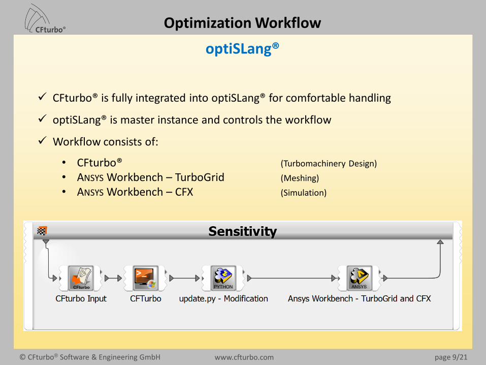
optiSLang®
Optimization Workflow
CFturbo® is fully integrated into optiSLang® for comfortable handling
optiSLang® is master instance and controls the workflow
Workflow consists of:
• CFturbo® (Turbomachinery Design)
• ANSYS Workbench – TurboGrid (Meshing)
• ANSYS Workbench – CFX (Simulation)
www.cfturbo.com© CFturbo® Software & Engineering GmbH page 10/21
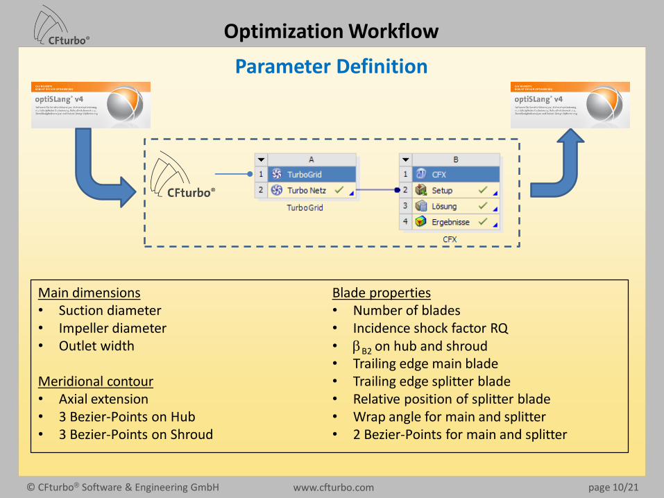
Parameter Definition
Optimization Workflow
Main dimensions• Suction diameter• Impeller diameter• Outlet width
Meridional contour• Axial extension• 3 Bezier-Points on Hub• 3 Bezier-Points on Shroud
Blade properties• Number of blades• Incidence shock factor RQ • bB2 on hub and shroud• Trailing edge main blade• Trailing edge splitter blade • Relative position of splitter blade• Wrap angle for main and splitter• 2 Bezier-Points for main and splitter
www.cfturbo.com© CFturbo® Software & Engineering GmbH page 11/21
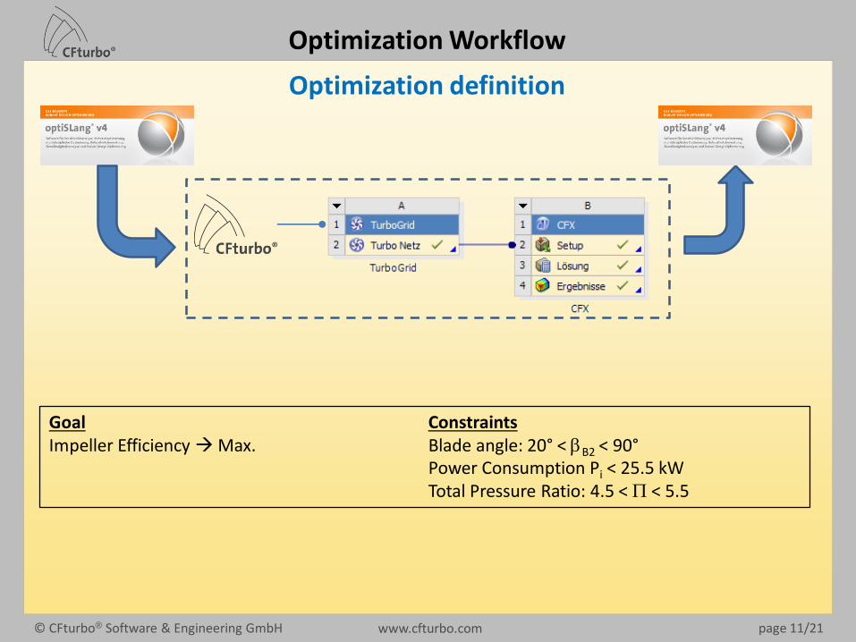
Optimization definition
Optimization Workflow
GoalImpeller Efficiency Max.
ConstraintsBlade angle: 20° < bB2 < 90°Power Consumption Pi < 25.5 kWTotal Pressure Ratio: 4.5 < P < 5.5
www.cfturbo.com© CFturbo® Software & Engineering GmbH page 12/21
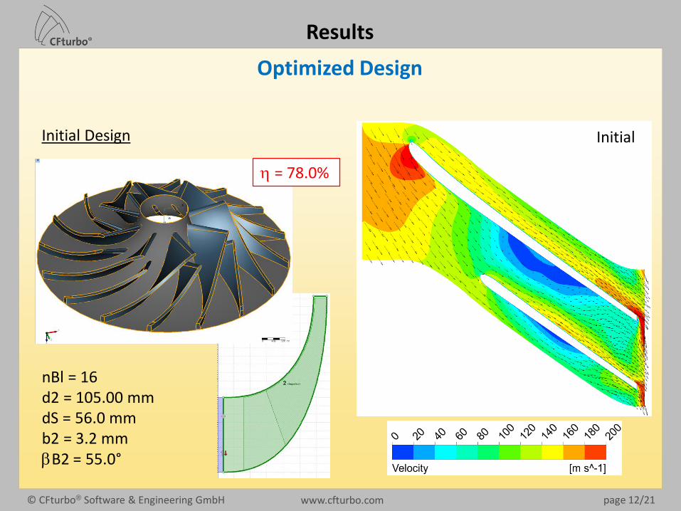
Optimized Design
Results
Initial Design
nBl = 16d2 = 105.00 mmdS = 56.0 mmb2 = 3.2 mmbB2 = 55.0°
h = 78.0%
Initial

www.cfturbo.com© CFturbo® Software & Engineering GmbH page 13/21
Optimized Design (2)
Results
Best design - Sensitivity
nBl = 22d2 = 103.42 mmdS = 51.3 mmb2 = 2.86 mmbB2 = 42°
h = 78.5%
Sensitivity Analysis
• 350 Designs generated, appr. 50% failed(>80% identified by CFturbo®)
• Random sampling gives no design improvement
• Explicable and optimizable behaviourcould be found
First Optimization (Adaptive Response Surface Method, ARSM)
• Search for optimized design in thecomplete design area
• Not applicable due to too many faildesigns

www.cfturbo.com© CFturbo® Software & Engineering GmbH page 14/21
Optimized Design (3)
Best design - EA1
nBl = 22d2 = 103.42 mmdS = 59.011 mmb2 = 2.9004 mmbB2 = 49.4°
Results
Second Optimization (EvolutionaryAlgorithm, EA)
• Search for optimized design in completedesign area (start: best designs fromsensitivity analysis)
• Stopped after 150 designs
• Design improvement ~5% in efficiency(compared to initial design)
h = 83.0%

www.cfturbo.com© CFturbo® Software & Engineering GmbH page 15/21
Optimized Design (4)
Best design - EA2
nBl = 28d2 = 102.01 mmdS = 59.011 mmb2 = 2.8581 mmbB2 = 47.5°
Results
Third Optimization (EA)
• Search for optimized design in extendeddesign area
• E.g. number of blades was limited to 22 and was extended to 30
• Start: best designs from prior EA Optimization
• Stopped after 200 design points
• Design improvement ~6% in efficiency(compared to initial design)
h = 84.1%
www.cfturbo.com© CFturbo® Software & Engineering GmbH page 16/21
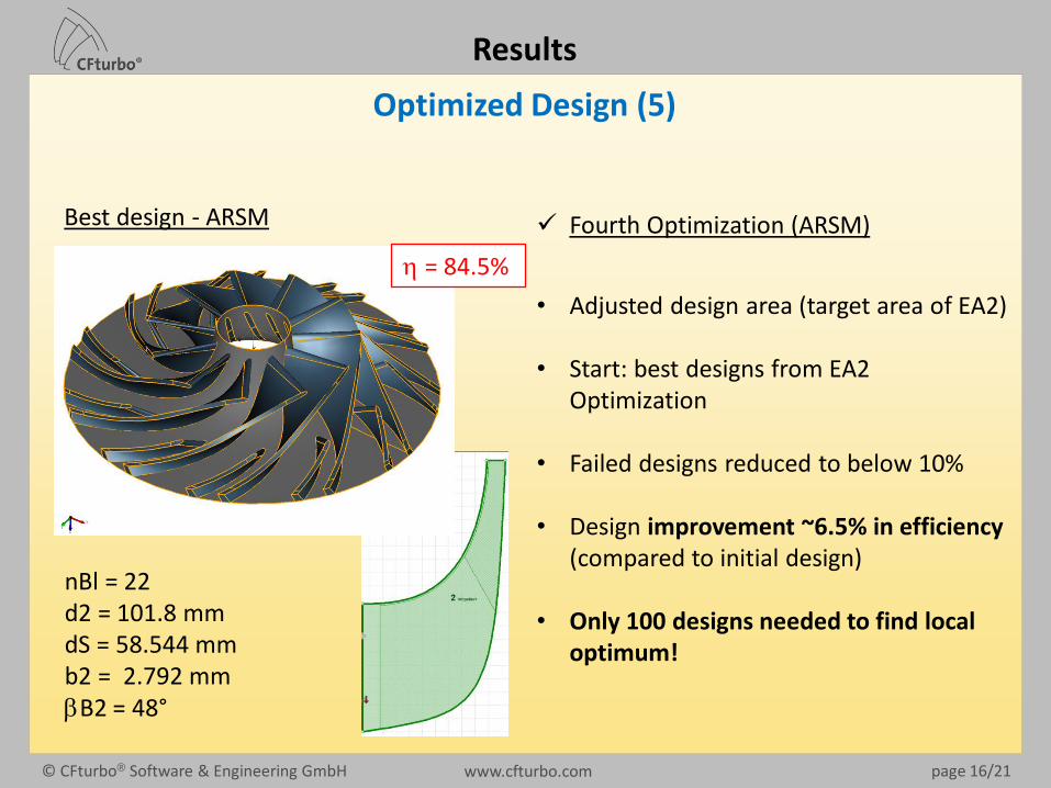
Optimized Design (5)
Best design - ARSM
nBl = 22 d2 = 101.8 mmdS = 58.544 mmb2 = 2.792 mmbB2 = 48°
Results
Fourth Optimization (ARSM)
• Adjusted design area (target area of EA2)
• Start: best designs from EA2 Optimization
• Failed designs reduced to below 10%
• Design improvement ~6.5% in efficiency(compared to initial design)
• Only 100 designs needed to find localoptimum!
h = 84.5%
www.cfturbo.com© CFturbo® Software & Engineering GmbH page 17/21
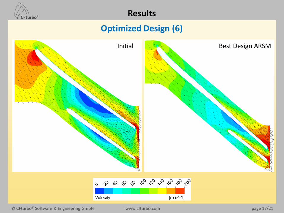
Optimized Design (6)
Results
Best Design ARSMInitial

www.cfturbo.com© CFturbo® Software & Engineering GmbH page 18/21
Existing workflow for single point turbomachinery optimization
Summary/Outlook
CFturbo®
Define operating pointQ, Dp, speed, Fluid properties
Inlet conditions
Fundamental equationsEuler-eq. of Turbomachinery, Continuity
equation, Momentum equation, …
Empirical functionsPublic knowledge,
Proprietory Know-How
Open issues:• TurboGrid inside Workbench does not allow parallel operation• Too many failed designs, when considering wide parameter range• CFturbo® designs are „pre-optimized“ – requires local search for optimum design• Empirical CFturbo® knowledge not available in optiSLang®
Empirical CFturbo® knowledge combined with optiSLang® algorithmsenables ultra-fast Turbomachinery optimization
www.cfturbo.com© CFturbo® Software & Engineering GmbH page 19/21
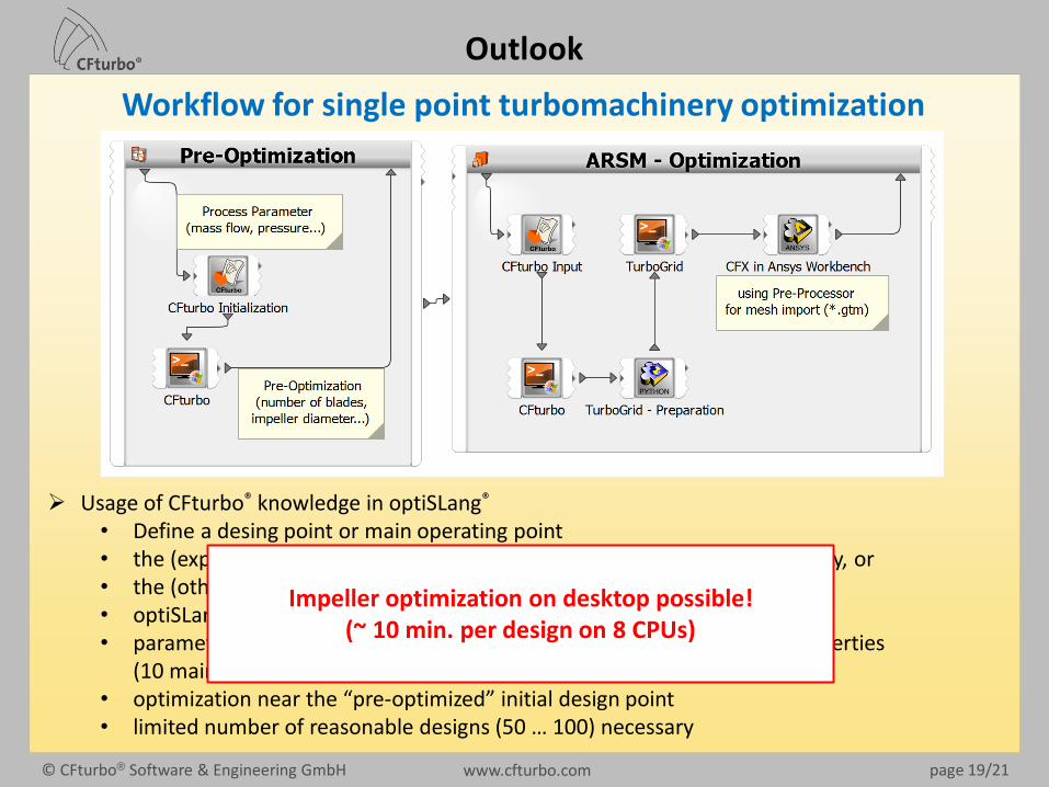
Workflow for single point turbomachinery optimization
Outlook
Usage of CFturbo® knowledge in optiSLang®
• Define a desing point or main operating point• the (experienced) user makes his initial design within CFturbo® interactively, or• the (other) users define their operating conditions in optiSLang®
• optiSLang® runs CFturbo® to get an initial “pre-optimized” design• parameter selection and limitation, e.g. meridional contour or blade properties
(10 main parameters for optimization)• optimization near the “pre-optimized” initial design point • limited number of reasonable designs (50 … 100) necessary
Impeller optimization on desktop possible!(~ 10 min. per design on 8 CPUs)

www.cfturbo.com© CFturbo® Software & Engineering GmbH page 20/21
Further developments - workflow for multi-purpose optimization
http://www.turbobygarrett.com/turbobygarrett/compressor_maps
• designs for wide compressor maps• determine surge and choke • full stage simulation including radial
diffusers and volute• enhanced accuracy by combined steady
and transient simulation• smart performance map predictions• …
Outlook

www.cfturbo.com© CFturbo® Software & Engineering GmbH page 21/21
Thank youfor your interest
and
S.Marth, M.Schimmelpfennig, D.Schneider (Dynardo)and
J. Einzinger (Ansys)
for their support!