initial rf ingress measurements for coaxial and utp … rf ingress measurements for coaxial and utp...
TRANSCRIPT
Initial RF Ingress Measurements for Coaxial and UTP Cables from
Automotive BCI Test
Larry Cohen
Ramin Shirani
1
Outline
• Overview
• BCI Test Procedure (to 400 MHz)
• BCI Setup
• BCI test results (MDI voltage)
• Observations
• Setup for > 400 MHz
• Next Steps
2

Overview
• Main Purpose: Initial measurement of the induced MDI port voltage from a standard automotive radiated immunity bulk current injection (BCI) test with different automotive harness cable types
–BCI test method is defined in ISO 11452-4; this procedure is generally used only up to 400 MHz for testing RF immunity of cable harnesses
–Test three different cable media:
• Single-shield RG174 (1.9 meter sample)
• PE-C100 (double-shielded RG174, 1.9 meter sample)
• UTP (single pair in jacket, 5 meter sample)
–All coaxial cable samples used FAKRA connectors
3
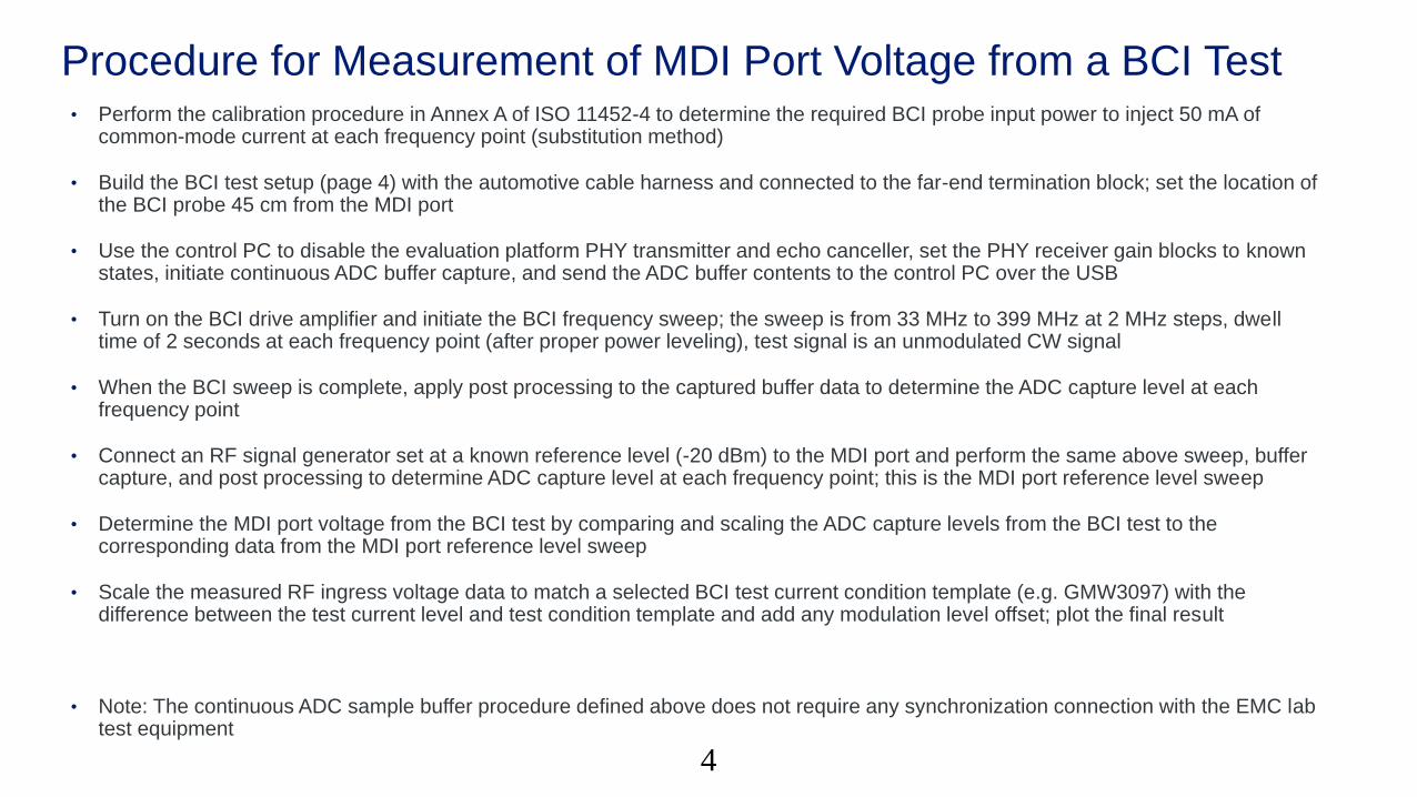
Procedure for Measurement of MDI Port Voltage from a BCI Test• Perform the calibration procedure in Annex A of ISO 11452-4 to determine the required BCI probe input power to inject 50 mA of
common-mode current at each frequency point (substitution method)
• Build the BCI test setup (page 4) with the automotive cable harness and connected to the far-end termination block; set the location of the BCI probe 45 cm from the MDI port
• Use the control PC to disable the evaluation platform PHY transmitter and echo canceller, set the PHY receiver gain blocks to known states, initiate continuous ADC buffer capture, and send the ADC buffer contents to the control PC over the USB
• Turn on the BCI drive amplifier and initiate the BCI frequency sweep; the sweep is from 33 MHz to 399 MHz at 2 MHz steps, dwell time of 2 seconds at each frequency point (after proper power leveling), test signal is an unmodulated CW signal
• When the BCI sweep is complete, apply post processing to the captured buffer data to determine the ADC capture level at each frequency point
• Connect an RF signal generator set at a known reference level (-20 dBm) to the MDI port and perform the same above sweep, buffer capture, and post processing to determine ADC capture level at each frequency point; this is the MDI port reference level sweep
• Determine the MDI port voltage from the BCI test by comparing and scaling the ADC capture levels from the BCI test to the corresponding data from the MDI port reference level sweep
• Scale the measured RF ingress voltage data to match a selected BCI test current condition template (e.g. GMW3097) with the difference between the test current level and test condition template and add any modulation level offset; plot the final result
• Note: The continuous ADC sample buffer procedure defined above does not require any synchronization connection with the EMC lab test equipment
4

Test Setup for BCI RF Ingress Measurement on Automotive Cable
5
Aquantia
PHY
Ev aluation
Board
Ground plane
table (90 cm
above floor)
GP
IB
RF Power Amplifier
(AR 50W-1000A)
Shielded chamber
Signal
Generator50
50
GPIB GPIB
50
Insulating cable
support
(~5 cm thick)
Bulk current injection
(BCI) probe
(FCC F-130-1)
Ferrite
clamp
INOUT
50
Directional
Coupler (40 dB)
FWD
CPL
Spectrum
Analyzer / RF
Power Meter
50
GPIB Control
Host PCGP
IB
Evaluation
Board Control
PC
US
B
Automotive cable channel
(UTP or coax)
The spectrum analyzer is used to monitor the
signal power to the BCI probe. At each frequency,
the signal generator output is adjusted to match
the calibration level at that frequency.
Unmodulated
CW signal
USB
Cable
Adapter
d
Shielded enclosure(Sits on 2 cm of
insulating material)
BCI probe calibrated as per Annex
A of ISO 11452-4 to 50 mA
(substitution method)
Sweep with BCI probe 45 cm from
the PHY platform (d = 45 cm), 30
MHz to 400 MHz
The DUT PHY transmitter and
echo canceller are disabled
(quiet) while the receiver is set
for continuous ADC buffer
capture. The contents of each
buffer capture is sent to the
control PC during the BCI
sweep.
The ingress levels at each
frequency are obtained from
post-processing of the
captured ADC buffer data.
Termination Block(Common ground
connected to ground
plane table)
120 VAC to +12 VDC
power supply inside
shielded enclosure
(+12 VDC is f loating)
+12
VDC
Power
Line Filter
Isolation
Transformer
120
VAC
Power
Converter
Filtered
Power
Mains
120
VAC
Earth ground
disconnected
To determine the actual MDI
port voltage, we perform a
reference capture sweep by
connecting a signal generator
with a known signal level (-20
dBm) directly into the MDI port
of the Evaluation Board.

Test Setup for BCI RF Ingress Measurement on Automotive Cable
6

7
Observations
• The observed RF ingress coupling from single-shielded coaxial cable (RG174) is considerably worse than double-shielded coaxial cable (PE-C100) and actually on par with UTP cable
• The induced MDI port voltage with (double-shielded) coaxial cable is at least 20 dB less than the corresponding MDI port voltage with UTP cabling at most frequency points
–Shield construction and termination matters !!
• The BCI test current was set at 50 mA to due to test equipment limitations
–Use of reduced test currents simplifies test setup by allowing simple copper cable interconnects instead of fiber optics
–This is permissible since we can simply scale the final measured results for a desired test template condition
• The different peak/null pattern in the UTP measurement is due to the longer cable sample that was tested (5m for UTP vs. 1.9m for coaxial cable samples)
8
Tests > 400 MHz
• Need to define a standard methodology to measure the RF ingress from different cable samples from 1 MHz to at least 3 GHz;
–BCI test methods to 400 MHz as shown here
• Need radiative immunity test for higher frequencies
• Existing standard ALSE (ISO 11452-2) test methods are recommended
9

ALSE Test Setup to Measure RF Ingress from 400 MHz to 3 GHz
10
Ground plane
table (90 cm
above floor)
1 meter
1.5 meters
DUT cable harness total
length < 2 meters
GPIB Control
Host PC GP
IB
Balun
RF Power
Amplifier
Antenna
(1 meter height)
Absorber-lined
shielded chamber
(ALSE)
Signal
Generator50
50
GPIB GPIB
50
Insulating cable
support
(5 cm thick)
DUT cable harness
must be 10 cm from the
edge of the table
Signal generator calibrated to
generate a known E-field level. This
eliminates the need for the E-field
sensor and field strength meter.
Control PC
GP
IB
Shielded
coaxial cable
Test field strength:
10 V/m to 30 V/m from 400 MHz to 2000 MHz (CW)
Use of test field strengths lower than that specified on
actual test (e.g 10 V/m) allows use of simple copper cable
interconnects in the scope capture interface (eliminates
need to use fiber optics). Measured result can be scaled
as necessary for higher field strengths.
Termination Block(Common ground
connected to ground
plane table)
0.1
meter
Shielded
enclosure
Shielded enclosure(Sits on 2 cm of
insulating material)
Cable
Adapter
Board
Digital Storage
Oscilloscope
(> 5GHz BW) GP
IB
The DSO is set to continuously
capture digitized input waveform
records and send them to the
control PC throught the GPIB
during the frequency sweep.
The ingress levels at each
frequency are obtained from
post-processing of the captured
data.
Use of DSO eliminates
bandwidth limitations of
PHY receiver
>1.5 meters
To determine loss or scaling
effects from cable adapter
board, we perform a reference
capture sweep by connecting
a signal generator with a
known signal level (-20 dBm)
directly at the Cable Adapter
Board MDI port

Next Steps
• Identify cable samples for future testing:
–STP cable, UTP cable in bundles
–Automotive cable setup input appreciated from OEMs
• Perform RF ingress measurement on cable samples up to 3 GHz using the BCI tests as here + absorber-lined shielded enclosure (ALSE) methodology defined in ISO 11452-2
11

Thank you.