injection and extraction - cern
TRANSCRIPT

Injection and Extraction (+Kickers Septa)
bull Introduction Kickers septa and normalised phase-space
bull Injection methods
ndash Single-turn hadron injection
ndash Injection errors filamentation and blow-up
ndash Multi-turn hadron injection
ndash Charge-exchange H- injection
ndash Lepton injection
bull Extraction methods
ndash Single-turn (fast) extraction
ndash Non-resonant and resonant multi-turn (fast) extraction
ndash Resonant multi-turn (slow) extraction
bull Linking machines
Frank Tecker CERN (BE-OP)
based on lectures by Matthew Fraser and MJ Barnes W Bartmann
J Borburgh V Forte B Goddard V Kain and M Meddahi
bull An accelerator has limited
dynamic range
bull Chain of stages needed to
reach high energy
bull Periodic re-filling of
storage rings like LHC
bull External facilities and
experiments
ndash eg ISOLDE
HIRADMAT AWAKEhellip
Beam transfer (into out of and
between machines) is necessary
Injection and extraction
CERN Accelerator Complex
Basics injection septum and kicker
Septum magnet
Kicker magnet
bull Kickers produce fast pulses rising their field within the particle-free gap in the
circulating beam (temporal separation)
bull Septa compensate for the relatively low kicker strength and approach closely
the circulating beam (spatial separation)
F-quad
t
kicker field
intensity injected
beam
Circulating beam
D-quad
bull Kicker bull Septum
hellipso we also call them
ldquoFast Pulsed Magnetsrdquo
Kickers - Magnetic parameters
B
HV conductor
Vertical aperture Vap
Ferrite
HV
By
m0
N times I
Vap
aelig
egrave
ccedilccedil
ouml
oslash
dividedivide
Return conductor
Horizontal
aperture Hap
Magnetic field
Derivation remember Ampegraverersquos Law
Lmag m
m0
N 2 timesHap
Vap
aelig
egrave
ccedilccedil
ouml
oslash
dividedivide
Magnet inductance
[per unit length]
Derivation remember Faradayrsquos Law
andFB = V dtograve
bull Dimensions Hap and Vap specified by beam parameters at kicker location
bull Ferrite (permeability μr asymp 1000) reinforces magnetic circuit and field uniformity in the gap
bull For fast rise-times the inductance must be minimised typically the number of turns N = 1
bull Kickers are often split into several magnet units powered independently
μr
μ0
V = LdI dt
A C-core geometry
commonly used at CERN
Pulsed magnet with very fast rise time (lt100 ns ndash few μs)
Magnetic
Septum coil 2 ndash 20 mm
Electrostatic
Thin wire or coil ~01 mm
Magnetic and electrostatic septum
E = V g
Typically V = 200 kV
E = 100 kVcm
E0 E=0
High voltage
electrodeHollow earth
electrode
Thin wire or
foil
g
Soft iron
Laminated yoke
Return coilSeptum coil
B0B=0
circulating
beam
circulating
beam
Bo = μ0I g
Typically I 5 - 25 kA
Single-turn injection ndash same plane
Septum magnet
Kicker magnet
bull Septum deflects the beam onto the closed orbit at the centre of the kicker
bull Kicker compensates for the remaining angle
bull Septum and kicker either side of D quad to minimise kicker strength
F-quad
t
kicker field
intensity injected
beam
lsquoboxcarrsquo stacking
Circulating beam
D-quad
Normalised phase space
bull Transform real transverse coordinates (x xrsquo s) to normalised co-ordinates
( ) where the independent variable becomes the phase advance μ
x(s) = e b(s) cos m(s)+m0[ ] m(s) =ds
b(s )0
s
ograve
X X m
Normalised phase space
1
x(s)
xrsquo(s)
1maxx
maxx
Area = p
maxX
maxX
Area = p
22 2 xxxx 22 XX
Real phase space Normalised phase space
Dm
- ea
b Dm =ds
b(s )S1
S2
ograve
Single-turn injectionNormalised phase space at centre of idealised septum
X
X
Single-turn injection
septum
Normalised phase space at centre of idealised septum
X
X
Single-turn injection
μ2 phase advance to kicker location
X
X
Single-turn injection
Kicker deflection places beam on central orbit
X
X
Normalised phase space at centre of idealised kicker
kicker
Injection oscillations
X
X
kicker - Δ
For imperfect injection the beam oscillates around the central orbit
eg kick error Δ
Injection oscillations
X
X
After 1 turnhellip
For imperfect injection the beam oscillates around the central orbit
eg kick error Δ
Injection oscillations
X
X
After 2 turnshellip
For imperfect injection the beam oscillates around the central orbit
eg kick error Δ
Injection oscillations
X
X
After 3 turns etchellip
For imperfect injection the beam oscillates around the central orbit
eg kick error Δ
Injection oscillations
bull Betatron oscillations with respect to the Closed Orbit
Transfer line LHC (first turn)
Horizontal
Vertical
bull Angular errors from septa and kicker have different orbit pattern
bull Correct the difference between injected beam and closed orbit
or 1st and 2nd turn
Filamentation
bull Non-linear effects (eg higher-order field components) introduce
amplitude-dependent effects into particle motion
bull Over many turns a phase-space oscillation is transformed into an
emittance increase
bull So any residual transverse oscillation will lead to an emittance blow-up
through filamentation
ndash ldquoTransverse damperrdquo systems are used to damp injection oscillations -
bunch position measured by a pick-up which is linked to a kicker
ndash Chromaticity coupled with a non-zero momentum spread at injection can
also cause filmentation often termed chromatic decoherence
bull See appendix for derivation of the emittance increase
X
X
Filamentation
X
X
Filamentation
X
X
Filamentation
X
X
Filamentation
X
X
Filamentation
X
X
Filamentation
X
X
Filamentation
X
X
Filamentation
X
X
Filamentation
X
X
Filamentation
bull Residual transverse oscillations lead to an effective emittance blow-
up through filamentation
bull Due to tune spread and energy spread the oscillation will not be
seen for long on a BPM signal
Inje
ctio
n o
scill
ation
Reference closed orbit
Filamentation - Decoherence
Multi-turn injection
bull For hadrons the beam density at injection can be limited either by
space charge effects or by the injector capacity
bull If we cannot increase charge density we can sometimes fill the
horizontal phase space to increase overall injected intensity
ndash Cannot inject into same phase space area as we would kick out the
beam located there
ndash If the acceptance of the receiving machine is larger than the delivered
beam emittance we can accumulate intensity
Multi-turn injection for hadrons
Septum magnet
bull No kicker but fast programmable bumpers
bull Bump amplitude decreases and a new batch injected turn-by-turn
bull Phase-space ldquopaintingrdquo
Programmable closed orbit bump
Circulating beam
1
Turn 1
Septum
X
X
Example CERN PSB injection high intensity beams fractional tune Qh asymp 025
Beam rotates π2 per turn in phase space
On each turn inject a new batch and reduce the bump amplitude
Multi-turn injection for hadrons
1
2
Turn 2
X
X
Septum
Multi-turn injection for hadrons
Example CERN PSB injection high intensity beams fractional tune Qh asymp 025
Beam rotates π2 per turn in phase space
3
2
1
Turn 3
X
X
Septum
Multi-turn injection for hadrons
Example CERN PSB injection high intensity beams fractional tune Qh asymp 025
Beam rotates π2 per turn in phase space
4
1
2
3
Turn 4
X
X
Septum
Multi-turn injection for hadrons
Example CERN PSB injection high intensity beams fractional tune Qh asymp 025
Beam rotates π2 per turn in phase space
3
2
4
51
Turn 5
X
X
Septum
Multi-turn injection for hadrons
Example CERN PSB injection high intensity beams fractional tune Qh asymp 025
Beam rotates π2 per turn in phase space
6
5
4
3
2
1
Turn 6
X
X
Septum
Multi-turn injection for hadrons
Example CERN PSB injection high intensity beams fractional tune Qh asymp 025
Beam rotates π2 per turn in phase space
7
6
5
4
3
2
1
Turn 7
X
X
Septum
Multi-turn injection for hadrons
Example CERN PSB injection high intensity beams fractional tune Qh asymp 025
Beam rotates π2 per turn in phase space
7
6
5
4
3
21
8
Turn 8
X
X
Septum
Multi-turn injection for hadrons
Example CERN PSB injection high intensity beams fractional tune Qh asymp 025
Beam rotates π2 per turn in phase space
7
6
5
4
3
2
1
8
9
Turn 9
X
X
Septum
Multi-turn injection for hadrons
Example CERN PSB injection high intensity beams fractional tune Qh asymp 025
Beam rotates π2 per turn in phase space
7
6
5
4
3
2
1
8
9
10
Turn 10
X
X
Septum
Multi-turn injection for hadrons
Example CERN PSB injection high intensity beams fractional tune Qh asymp 025
Beam rotates π2 per turn in phase space
7
6
5
4
3
2
1
8
9
10
11
Turn 11
X
X
Septum
Multi-turn injection for hadrons
Example CERN PSB injection high intensity beams fractional tune Qh asymp 025
Beam rotates π2 per turn in phase space
7
6
5
4
3
21
8
9
10
11
Turn 12
X
X
Septum
Multi-turn injection for hadrons
Example CERN PSB injection high intensity beams fractional tune Qh asymp 025
Beam rotates π2 per turn in phase space
7
6
5
4
3
2
1
8
9
10
11
Turn 13
X
X
Septum
Multi-turn injection for hadrons
Example CERN PSB injection high intensity beams fractional tune Qh asymp 025
Beam rotates π2 per turn in phase space
7
6
5
4
3
2
1
8
9
10
11
Turn 14
X
X
Septum
Multi-turn injection for hadrons
Example CERN PSB injection high intensity beams fractional tune Qh asymp 025
Beam rotates π2 per turn in phase space
7
6
5
4
3
2
1
8
9
10
11
Turn 15
In reality filamentation (often space-charge driven) occurs to produce a quasi-
uniform beam
X
X
Phase space has been ldquopaintedrdquo
Multi-turn injection for hadrons
Charge exchange H- injection
bull Multi-turn injection is essential to accumulate high intensity
bull Disadvantages inherent in using an injection septum
ndash Width of several mm reduces aperture
ndash Beam losses from circulating beam hitting septum
bull typically 30 ndash 40 for the CERN PSB injection at 50 MeV
ndash Limits number of injected turns to 10 ndash 20
bull Charge-exchange injection provides elegant alternative
ndash Possible to ldquocheatrdquo Liouvillersquos theorem which says that emittance is
conservedhellip
ndash Convert H- to p+ using a thin stripping foil allowing injection into the
same phase space area
Charge exchange H- injection
Injection chicane dipoles
Circulating p+
Stripping foil
H0
Circulating p+
Start of injection process
Charge exchange H- injection
Circulating p+
Stripping foil
End of injection process with painting
H0
Injection chicane dipoles
Displace orbit
Circulating p+
Accumulation process on foil
V Forte Performance of the CERN PSB at 160 MeV with H- charge exchange injection PhD thesis ndash CERN and Universiteacute Blaise Pascal
bull Linac4 connection to the PS booster at 160 MeV
ndash H- stripped to p+ with an estimated efficiency asymp98 with C foil 200 μgcm-2
Charge exchange H- injection
bull Paint uniform transverse phase space density by modifying closed
orbit bump and steering injected beam
bull Foil thickness calculated to double-strip most ions (asymp99)
ndash 50 MeV ndash 50 μgcm-2
ndash 800 MeV ndash 200 μgcm-2 (asymp 1 μm of C)
bull Carbon foils generally used ndash very fragile
bull Injection chicane reduced or switched off after injection to avoid
excessive foil heating and beam blow-up
bull Longitudinal phase space can also be painted turn-by-turn
ndash Variation of the injected beam energy turn-by-turn (linac voltage scaled)
ndash Chopper system in linac to match length of injected batch to bucket
H- injection - painting
Timexrsquo vs x yrsquo vs y y vs x
Note injection into
same phase
space area as
circulating beam
asymp100 turns
Lepton injection
bull Single-turn injection can be used as for hadrons however lepton
motion is strongly damped (different with respect to proton or ion
injection)
ndash Synchrotron radiation
bull see Electron Beam Dynamics lectures by L Rivkin
bull Can use transverse or longitudinal damping
ndash Transverse - Betatron accumulation
ndash Longitudinal - Synchrotron accumulation (2 x faster than transverse)
Betatron lepton injection
bull Beam is injected with an angle with respect to the closed orbit
bull Injected beam performs damped betatron oscillations about the closed orbit
Septum magnet
Closed orbit bumpers or kickers
Circulating
beam
Betatron lepton injection
Injected bunch performs damped betatron oscillations
In LEP at 20 GeV the damping time was about 6rsquo000 turns (06 seconds)
X
X
Synchrotron lepton injection
Septum magnet
bull Beam injected parallel to circulating beam onto dispersion orbit of a
particle having the same momentum offset Δpp
bull Injected beam makes damped synchrotron oscillations at Qs but does
not perform betatron oscillations
Closed orbit bumpers or kickersxs = Dx Δpp0
xsp = p0
p = p0 + Δp
Inject an off-momentum beam
at a location with dispersion
Synchrotron lepton injection
F
E
Double batch injection possiblehellip
Longitudinal damping time in LEP was ~3rsquo000 turns (2x faster than transverse)
Injection 1 (turn N)
Injection 2 (turn N + Qs2)
Stored beam
RF bucket
Synchrotron lepton injection in LEP
Synchrotron injection in LEP gave improved background for LEP experiments
due to small orbit offsets in zero dispersion straight sections
Injection - summary
bull Several different techniques using kickers septa and bumpers
ndash Single-turn injection for hadrons
bull Boxcar stacking transfer between machines in accelerator chain
bull Angle position errors injection oscillations
bull Uncorrected errors filamentation emittance increase
ndash Multi-turn injection for hadrons
bull Phase space painting to increase intensity
bull H- injection allows injection into same phase space area
ndash Lepton injection take advantage of damping
bull Less concerned about injection precision and matching
Extraction
bull Different extraction techniques exist depending on requirements
ndash Fast extraction le1 turn
ndash Non-resonant (fast) multi-turn extraction few turns
ndash Resonant low-loss (fast) multi-turn extraction few turns
ndash Resonant multi-turn extraction many thousands of turns
bull Usually higher energy than injection stronger elements (intBdl)
ndash At high energies many kicker and septum modules may be required
ndash To reduce kicker and septum strength beam can be moved near to
septum by closed orbit bump
ndash Beam size scales with 1 120574 =gt smaller than injection
Fast single turn extraction
Septum magnet
Kicker magnet
bull Bumpers move circulating beam close to septum to reduce kicker strength
bull Kicker deflects the entire beam into the septum in a single turn
bull Most efficient (lowest deflection angles required) for π2 phase advance
between kicker and septum
Closed orbit bumpers
Entire beam kicked into septum gap and extracted over a single turn
F-quad D-quad
Circulating
beam
t
kicker field
intensity
Fast single turn extraction
bull For transfer of beams between accelerators in an injector chain
bull For secondary particle production
ndash eg neutrinos radioactive beams
bull Losses from transverse scraping or from particles in extraction gap
ndash Fast extraction from SPS to CNGS
1E+08
1E+09
1E+10
1E+11
0 1 2 3 4 5 6 7 8 9 10 11 12 13 14 15time us
p+
00
02
04
06
08
10
12 kk
o
Intensity [10^9 p25ns]
Kicker strength
Particles in SPS extraction kicker rise- and fall-time gaps
Multi-turn extraction
bull Some filling schemes require a beam to be injected in several turns to
a larger machinehellip
bull And very commonly Fixed Target physics experiments and medical
accelerators often need a quasi-continuous flux of particleshellip
bull Multi-turn extractionhellip
ndash Fast Non-resonant and resonant multi-turn ejection (few turns) for filling
bull eg PS to SPS at CERN for high intensity proton beams (gt25 1013 protons)
ndash Slow Resonant extraction (ms to hours) for experiments
Extracted beamMagnetic
septum
bull Fast bumper deflects the whole beam onto the septum
bull Beam extracted in a few turns with the machine tune rotating the beam
bull Intrinsically a high-loss process thin septum essential
bull Often combine thin electrostatic septa with magnetic septa
Non-resonant multi-turn extraction
Fast closed orbit bumpers
Beam bumped to septum part of beam lsquoshavedrsquo off each turn
Electrostatic
septum
Non-resonant multi-turn extraction
bull Example system CERN PS to SPS Fixed-Target lsquocontinuous transferrsquo
ndash Accelerate beam in PS to 14 GeVc
ndash Empty PS machine (21 μs long) in 5 turns into SPS
ndash Do it again
ndash Fill SPS machine (11 x CPS 23 μs long)
ndash Quasi-continuous beam in SPS (2 x 1 μs gaps)
ndash Total intensity per PS extraction asymp 3 1013 p+
ndash Total intensity in SPS asymp 5 1013 p+
Extracted beam
beam
To the SPS
The PS
Non-resonant multi-turn extraction
X
X
CERN PS to SPS 5-turn continuous transfer ndash 1st turn
Qh = 025
1 2 3 4 5
Bump vs turn
1
2
3
4
5
septum
Non-resonant multi-turn extraction
X
X
CERN PS to SPS 5-turn continuous transfer ndash 2nd turn
Qh = 025
1 2 3 4 5
Bump vs turn
1
2
3
4 5
septum
Non-resonant multi-turn extraction
X
X
CERN PS to SPS 5-turn continuous transfer ndash 3rd turn
Qh = 025
1 2 3 4 5
Bump vs turn
septum
1
2
3
4
5
Non-resonant multi-turn extraction
X
X
CERN PS to SPS 5-turn continuous transfer ndash 4th turn
Qh = 025
1 2 3 4 5
Bump vs turn
septum
1
2
3
45
Non-resonant multi-turn extraction
X
X
CERN PS to SPS 5-turn continuous transfer ndash 5th turn
Qh = 025
5
1 2 3 4 5
Bump vs turn
Non-resonant multi-turn extraction
bull CERN PS to SPS 5-turn continuous transfer
ndash Losses impose thin septumhellip
hellip an electrostatic septum is needed in addition to the magnetic septum
ndash Still about 15 of beam lost in PS-SPS CT
ndash Difficult to get equal intensities per turn
ndash Different trajectories for each turn
ndash Different emittances for each turn
X
X
1
X
X
2
X
X
3
X
X
4
X
X
5
I
1 2 3 4 5
Resonant multi-turn (fast) extraction
bull Adiabatic capture of beam in stable ldquoislandsrdquo
- Use non-linear fields (sextupoles and octupoles) to create islands of
stability in phase space
- A slow (adiabatic) tune variation to cross a resonance and to drive
particles into the islands (capture) with the help of transverse excitation
(using damper)
- Variation of field strengths to separate the islands in phase space
bull Several big advantages
ndash Losses reduced significantly (no particles at the septum in transverse
plane)
ndash Phase space matching improved with respect to existing non-resonant
multi-turn extraction - lsquobeamletsrsquo have similar emittance and optical
parameters
Resonant multi-turn (fast) extraction
a Unperturbed beam
b Increasing non-linear
fields
a Beam captured in
stable islands
b Islands separated and
beam bumped across
septum ndash extracted in
5 turns
(see Non-Linear Beam Dynamics lectures
by Y Papaphilippou)
Courtesy M Giovannozzi MTE Design Report CERN-2006-011 2006
Resonant multi-turn (fast) extraction
Septum wire
1 2 3 4 5
Bump vs turn
Qh = 025
a Unperturbed beam
b Increasing non-linear
fields
a Beam captured in
stable islands
b Islands separated and
beam bumped across
septum ndash extracted in
5 turns
Courtesy M Giovannozzi MTE Design Report CERN-2006-011 2006
Extracted beam
bull Slow bumpers move the beam near the septum
bull Tune adjusted close to nth order betatron resonance
bull Multipole magnets excited to define stable area in phase space size
depends on ΔQ = Q - Qr
Resonant multi-turn (slow) extraction
Closed orbit bumpers
Non-linear fields excite resonances that drive the beam slowly across the septum
Magnetic
septum
Electrostatic
septum
Resonant multi-turn (slow) extraction
bull 3rd order resonances ndash see lectures by Y Papaphilippou
ndash Sextupole fields distort the circular normalised phase space particle trajectories
ndash Stable area defined delimited by unstable Fixed Points
ndash Sextupole magnets arranged to produce suitable phase space orientation of the stable triangle at thin electrostatic septum
ndash Stable area can be reduced byhellip
bull Increasing the sextupole strength orhellip
bull Fixing the sextupole strength and scanning the machine tune Qh (and therefore the resonance) through the tune spread of the beam
bull Large tune spread created with RF gymnastics (large momentum spread) and large chromaticity
2
21 1
kQR fp
Rfp
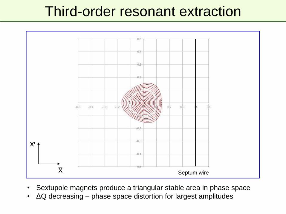
Third-order resonant extraction
bull Particles distributed on emittance contours
bull ΔQ large ndash no phase space distortion
X
X
Septum wire
Third-order resonant extraction
bull Sextupole magnets produce a triangular stable area in phase space
bull ΔQ decreasing ndash phase space distortion for largest amplitudes
X
X
Septum wire
Third-order resonant extraction
X
X
Septum wire
bull Sextupole magnets produce a triangular stable area in phase space
bull ΔQ decreasing ndash phase space distortion for largest amplitudes
Third-order resonant extraction
X
X
Septum wire
bull Sextupole magnets produce a triangular stable area in phase space
bull ΔQ decreasing ndash phase space distortion for largest amplitudes
Third-order resonant extraction
X
X
Septum wire
bull Sextupole magnets produce a triangular stable area in phase space
bull ΔQ decreasing ndash phase space distortion for largest amplitudes
Third-order resonant extraction
bull Largest amplitude particle trajectories are significantly distorted
bull Locations of fixed points noticeable at extremities of phase space triangle
X
X
Septum wire
Third-order resonant extraction
X
X
Septum wire
bull ΔQ small enough that largest amplitude particle trajectories are unstable
bull Unstable particles follow separatrix branches as they increase in amplitude
Third-order resonant extraction
X
X
Septum wire
bull Stable area shrinks as ΔQ becomes smaller
Third-order resonant extraction
X
X
Septum wire
bull Separatrix position in phase space shifts as the stable area shrinks
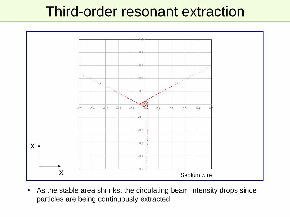
Third-order resonant extraction
bull As the stable area shrinks the circulating beam intensity drops since
particles are being continuously extracted
X
X
Septum wire
Third-order resonant extraction
X
X
Septum wire
bull As the stable area shrinks the circulating beam intensity drops since
particles are being continuously extracted
Third-order resonant extraction
X
X
Septum wire
bull As the stable area shrinks the circulating beam intensity drops since
particles are being continuously extracted
Third-order resonant extraction
X
X
Septum wire
bull As the stable area shrinks the circulating beam intensity drops since
particles are being continuously extracted
Third-order resonant extraction
X
X
Septum wire
bull As ΔQ approaches zero the particles with very small amplitude are
extracted
Slow extracted spill quality
Reducing Q with main machine quadrupoles can be augmented with a
lsquoservorsquo quadrupole which can modulate Q in a servo loop acting on
a measurement of the spill intensity
50 Hz
10 Hz
An example of a spill at SPS to the North Area with large n x 50 Hz
components and another noise source at 10 Hz
bull The slow-extraction is a resonant process and it amplifies the smallest
imperfections in the machine- eg spill intensity variations can be explained by ripples in the current of the
quads (mains n x 50 Hz) at the level of a few ppm
- Injection of n x 50 Hz signals in counter-phase on dedicated quads can be
used to compensate
Extraction - summary
bull Several different techniques
ndash Single-turn fast extraction
bull for transfer between machines in accelerator chain beam abort etc
ndash Non-resonant (fast) multi-turn extraction
bull slice beam into equal parts for transfer between machine over a few turns
ndash Resonant low-loss (fast) multi-turn extraction
bull create stable islands in phase space slice off over a few turns
ndash Resonant (slow) multi-turn extraction
bull create stable area in phase space slowly drive particles into resonance long spill over many thousand turns
1 Extract a beam out of one machine initial beam parameters
2 Transport this beam towards the following machine (or experiment)
3 Inject this beam into a following machine with a predefined optics
Transfer line optics has to produce required beam parameters for matching
Linking Machines
Extraction
Transfer
Injection
s
(αx βx Dx Drsquoxαy βy Dy Drsquoy)1 M12
(αx βx Dx Drsquoxαy βy Dy Drsquoy)2
Linking Machines
bull Beams have to be transported from extraction of one machine to
injection of the next machine
- Trajectory must be matched in all 6 geometric degrees of freedom
(xyzθΦψ)
bull Linking the optics is a complicated process
- Parameters at start of line have to be propagated to matched parameters
at the end of the line (injection to another machine fixed target etc )
- Need to ldquomatchrdquo 8 variables (αx βx Dx Drsquox and αy βy Dy Drsquoy)
- Done with number of independently power (ldquomatchingrdquo) quadrupoles
- Maximum β and D values are imposed by magnetic apertures
- Other constraints exist
- Phase conditions for collimators
- Insertions for special equipment like stripping foils
- hellip
bull Matching with computer codes and relying on mixture of theory experience
intuition trial and error
Optics Matching example
0
50
100
150
200
250
300
0 250 500 750 1000 1250 1500 1750 2000 2250 2500 2750 3000 3250 3500 3750 4000
S [m]
[
m]
BETXBETY
SPS LHCRegular lattice (FODO)
(elements all powered in series
with same strengths)
Final matching
section
SPS to LHC Transfer Line (3 km)Extraction
point Injection
point
Initial matching
section
Independently powered (tuneable) quadrupoles
Independently powered (tuneable) quadrupoles and (in this case) passive
protection devices
Need to match 8 variables (TWISS parameters) for propagation from start to end of a transfer
Optical Mismatch at Injection
bull Filamentation fills larger ellipse with same shape as matched ellipse
x
xrsquo
Turn 0
Turn N
Time
bull Dispersion mismatch at injection will also cause emittance blow-up
Further reading and references
bull Lots of resources presented at the recent Specialised CAS School
bull Beam Injection Extraction and Transfer 10-19 March 2017 Erice Italy
bull httpscaswebcernchschoolserice-2017
Terminating
Resistor
Transmission
Line
Z
Kicker
Magnet
Z
Z
Main
Switch
PFN or
PFL
Z
RCPS
Dump
Switch
Dump
ResistorZ
Single-way Delay τp
Simplified kicker system schematic
Terminating
Resistor
Transmission
Line
Z
Kicker
Magnet
Z
Z
Main
Switch
PFN or
PFL
Z
RCPS
Dump
Switch
Dump
ResistorZ
Single-way Delay τp
bull Main sub-systems (ldquocomponentsrdquo) of kicker system
ndash RCPS = Resonant Charging Power Supply
ndash PFL = Pulse Forming Line (coaxial cable) or PFN = Pulse Forming
Network (lumped elements)
ndash Fast high power switch(es)
ndash Transmission line(s) coaxial cable(s)
ndash Kicker Magnet
ndash Terminators (resistive)
Matched impedance example
Terminating
Resistor
Transmission
Line
Z
Kicker
Magnet
Z
Z
Main
Switch
PFN or
PFL
Z
RCPS
Dump
Switch
Dump
ResistorZ
Single-way Delay τp
Simplified kicker system schematic
Terminating
Resistor
Transmission
Line
Z
Kicker
Magnet
Z
Z
Main
Switch
PFN or
PFL
Z
RCPS
Dump
Switch
Dump
ResistorZ
Single-way Delay τp
bull PFLPFN charged to voltage V0 by the RCPS
bull Main switch is closedhellip
hellipvoltage pulse of V02 flows through kicker
bull Once the pulse reaches the (matched) terminating resistor full-field has
been established in the kicker magnet
bull Pulse length controlled between t = 0 and 2p with dump switch
Matched impedance example
PFLPFN
Pulse Forming Line (PFL)
bull Low-loss coaxial cable
bull Fast and ripple-free pulses
bull Attenuation (droop ~1) becomes
problematic for pulses gt 3 μs
bull Above 50 kV SF6 pressurized PE
tape cables are used
bull Bulky 3 μs pulse ~ 300 m of cable
Pulse Forming Network (PFN)
bull Artificial coaxial cable made of lumped
elements
bull For low droop and long pulses gt 3 μs
bull Each cell individually adjustable
adjustment of pulse flat-top difficult
and time consuming
Reels of PFL used at the PS complex (as old as the photograph) SPS extraction kicker (MKE) PFN (17 cells)
Power semiconductor switches
bull Suitable for scenarios where erratic
turn-on is not allowed
bull For example LHC beam dump
kickers held at nominal voltage
throughout operation (gt10h) ready to
fire and safely abort at any moment
bull Hold off up to 30 kV and switch up to
18 kA
bull Slower switching gt 1 μs (~18kAμs)
bull Low maintenance
Switches
~ 3
40 m
m
Thyratrons
bull Deuterium gas thyratrons are commonly used
bull Hold off 80 kV and switch up to 6 kA
bull Fast switching ~ 30 ns (~150 kAμs)
bull Erratic turn-on use with RCPS to reduce hold-off time
ThyratronStack of high-power semiconductor
switches (GTOs)
Terminating
Resistor
Transmission
Line
Z
Kicker
Magnet
Z
Z
Main
Switch
PFN or
PFL
Z
RCPS
Dump
Switch
Dump
ResistorZ
Single-way Delay τp
Simplified kicker system schematic
Terminating
Resistor
Transmission
Line
Z
Kicker
Magnet
Z
Z
Main
Switch
PFN or
PFL
Z
RCPS
Dump
Switch
Dump
ResistorZ
Single-way Delay τp
V
distancet pvp
bull Pulse forming network or line (PFLPFN) charged to voltage V0 by the
resonant charging power supply (RCPS)
ndash RCPS is de-coupled from the system through a diode stack
t = 0
V0
ttime
int
kicker
field
t fill
Terminating
Resistor
Transmission
Line
Z
Kicker
Magnet
Z
Z
Main
Switch
PFN or
PFL
Z
RCPS
Dump
Switch
Dump
ResistorZ
Single-way Delay τp
Simplified kicker system schematic
Terminating
Resistor
Transmission
Line
Z
Kicker
Magnet
Z
Z
Main
Switch
PFN or
PFL
Z
RCPS
Dump
Switch
Dump
ResistorZ
Single-way Delay τp
t = 2t p +t fill
distance
V
t pvp
ttime
V0
bull A kicker pulse of approximately 2p is imparted on the beam and all
energy has been emptied into the terminating resistor
2t p
t fill t p t fill
I =V0
2Z
t fill
int
kicker
field
Terminating
Resistor
Transmission
Line
Z
Kicker
Magnet
Z
Z
Main
Switch
PFN or
PFL
Z
RCPS
Dump
Switch
Dump
ResistorZ
Single-way Delay τp
Simplified kicker system schematic
Terminating
Resistor
Transmission
Line
Z
Kicker
Magnet
Z
Z
Main
Switch
PFN or
PFL
Z
RCPS
Dump
Switch
Dump
ResistorZ
Single-way Delay τp
t raquo 2t p
distance
V
t pvp
ttime
V0
bull Kicker pulse length can be changed by adjusting the relative timing of
dump and main switches
ndash eg if the dump and main switches are fired simultaneously the pulse
length will be halved and energy shared on dump and terminating resistors
2t p
t fill t p
I =V0
2Z
t fill
t fill
int
kicker
field
Short circuit mode
bull Short-circuiting the termination offers twice the kick (for a given kicker magnet)
- Fill time of kicker magnet is doubled
- Diode as dump switch provides solution for fixed pulse length
Terminating
Resistor
Transmission
Line
Z
Kicker
Magnet
Z
Z
Main
Switch
PFN or
PFL
Z
RCPS
Dump
Switch
Dump
ResistorZ
Single-way Delay τpTerminating
Resistor
Transmission
Line
Z
Kicker
Magnet
Z
Z
Main
Switch
PFN or
PFL
Z
RCPS
Dump
Switch
Dump
ResistorZ
Single-way Delay τp
distance
Vt pvp
V0
Dump Diode
Short Circuit
-V0
2
ttime
t raquo 2(t p +t fill )
Boundary condition at
short-circuit
V = 0 doubling I
Diode conducts as voltage
flips sign and match dump
resistor absorbs energy
I =V0
Z
2(t p +t fill )
t fill
int
kicker
field
I- =V0
2Z
Kicker magnets ndash design options
bull Type ldquolumped inductancerdquo or ldquodistributed inductancerdquo (transmission line)
bull Other considerations
ndash Machine vacuum kicker in-vacuum or external
ndash Aperture geometry of ferrite core
ndash Termination matched impedance or short-circuit
VZ Lmag
From generator
(eg PFN)V
Z =Lcell
Ccell
bull simple magnet design
bull magnet must be nearby the
generator to minimise inductance
bull exponential field rise-time
bull slow rise-times ~ 1 μs
bull complicated magnet design
bull impedance matching important
bull field rise-time depends on propagation
time of pulse through magnet
bull fast rise-times ltlt 1 μs
Ccell
2
Ccell
2
Ccell
2
Ccell
2
Ccell
2
Ccell
2
Lcell Lcell Lcell
Cell 1hellip Cell n - 1 hellip Cell n
t = n Lcell timesCcell = nLcell
Z=Lmag
Z
I =V
Z(1- e-t t ) t =
Lmag
Z
Lmag = nLcellFrom generator
(eg PFN)
Magnets ndash transmission line
bull Todayrsquos fast (rise-times of lt few hundred ns) kicker magnets are generally
ferrite loaded transmission lines
ndash Ferrite C-cores are sandwiched between HV plates
ndash Grounded plates are interleaved to form a capacitor to ground
B
Ground plate
HV conductor
Return
conductor
Ferrite
HV
End Viewand so onhellip
beam
Side Viewcell
Magnets ndash transmission line
bull Todayrsquos fast (rise-times of lt few hundred ns) kicker magnets are generally
ferrite loaded transmission lines
ndash Kicker magnets consists of many relatively short cells to approximate a
broadband coaxial cable
LcLc
Cc2Cc2Cc2
Lc
Cc2Cc2
Lc
Cc2Cc2
0
Cc2
cell
1 2 (n-1) n
A real kickerhellip
Prototype for AGS
injection kicker upgrade
beam
and so onhellip
Side Viewcell
Electrostatic septum
bull Thin septum ~ 01 mm needed for high extraction efficiency
ndash Foils typically used
ndash Stretched wire arrays provide thinner septa and lower effective density
bull Challenges include conditioning and preparation of HV surfaces vacuum
in range of 10-9 ndash 10-12 mbar and in-vacuum precision position alignment
E
(up to 10 MVm
in UHV)
x
yz
d (typically 10 to 35 mm)
V (up to 300 kV)
circulating beam
extracted
beam
septum foil
(Mo or Z-Re)
electrode
(Al Ti SS)
support
Grounded support
Electrode (HV)Foil
Foil TensionersBake-out lamps for UHV
Electrostatic septum
bull At SPS we slow-extract 400 GeV protons using approximately 15 m of septum split into 5 separate vacuum tanks each over 3 m long
- Alignment of the 60 - 100 μm wire array over 15 m is challenging
DC direct drive magnetic septum
magnet yoke (laminated steel)septum
x
yz
Cooling
Electrical connectionsCirculating beam
vacuum
chamber
extracted
beam
0
B
x
x
septum
(typically 6 to 20 mm)
g
(typically
25 - 60 mm)
bull Continuously powered rarely under vacuum
bull Multi-turn coil to reduce current needed but cooling still an issue
ndash Cooling water circuits flow rate typically at 12 ndash 60 lmin
ndash Current can range from 05 to 4 kA and power consumption up to 100 kW
rear
conductor
B
septum
(typically 3 to 20 mm)
circulating
beamrear
conductor
septum
conductor
extracted
beam0
B
x
x
Direct drive pulsed magnetic septum
x
yz
Beam ldquomonitorrdquo
Beam screenBake-out lamps for UHV
Septumbull In vacuum to minimise distance between circulating and extracted beam
bull Single-turn coil to minimise inductance bake-out up to 200 degC (~10-9 mbar)
bull Pulsed by capacitor discharge (third harmonic flattens the pulse)
ndash Current in range 7 ndash 40 kA with a few ms oscillation period
ndash Cooling water circuits flow rate from 1 ndash 80 lmin
g
(typically
18 - 60 mm)
magnet yoke (laminated steel)
B
Appendix
Injection errors
kicker
bpm1 bpm2
phase m ~p2 ~p2~p2
septum
Angle errors
sk
Measured
Displacements
d12
s k
d1
d2
Dqk bk
At kicker location
Injection errors
kicker
bpm1 bpm2
phase m ~p2 ~p2~p2
septum
Angle errors
sk
Measured
Displacements
d12
d1 = s (s1) sin (m1 ndash ms) + k (k1) sin (m1 ndash mk)
asymp k (k1)
s k
d1
d2
Dqk bk
x
b1
raquo Dqk bk
At BPM1 location
d2 = s (s2) sin (m2 ndash ms) + k (k2) sin (m2 ndash mk)
asymp -s (s2)
Blow-up from steering error
X
X
Misinjected
beam
Matched
particles
L
A0
bull The new particle coordinates in normalised phase space are
Xerror = X0 +Lcosq
X error = X 0+Lsinq
bull For a general particle distribution
where Ai denotes amplitude in
normalised phase of particle i
bull The emittance of the distribution is
L = Da ematched
bull So we plug in the new coordinates
bull Taking the average over distribution
bull Giving the diluted emittance as
Blow-up from steering error
0
X
X
Effect of steering error on a given particle
Matched
particles
A
L
= (X0 +Lcosq)2 + (X 0+Lsinq)2
= X0
2 +X 02+2L(X0 cosq +X 0sinq)+L2
cos2q +sin2q =1
0
= 2ematched +L2
ediluted =ematched +L2
2
L = Da ematched
=ematched 1+Da2
2
eacute
eumlecirc
ugrave
ucircuacute
Blow-up from steering error
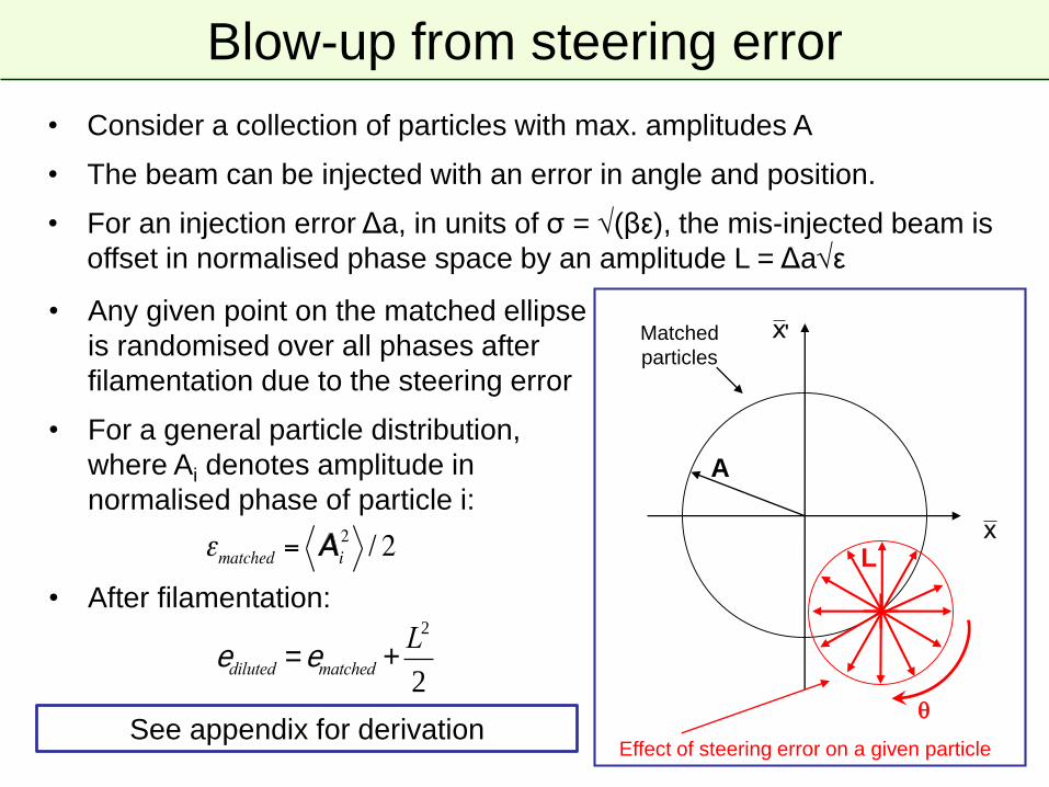
bull Consider a collection of particles with max amplitudes A
bull The beam can be injected with an error in angle and position
bull For an injection error Δa in units of σ = (βε) the mis-injected beam is
offset in normalised phase space by an amplitude L = Δaε
X
X
Misinjected
beam
Matched
particles
L
A
Blow-up from steering error
bull Consider a collection of particles with max amplitudes A
bull The beam can be injected with an error in angle and position
bull For an injection error Δa in units of σ = (βε) the mis-injected beam is
offset in normalised phase space by an amplitude L = Δaε
X
XMatched
particles
A
L
bull Any given point on the matched ellipse
is randomised over all phases after
filamentation due to the steering error
Effect of steering error on a given particle
Blow-up from steering error
bull Consider a collection of particles with max amplitudes A
bull The beam can be injected with an error in angle and position
bull For an injection error Δa in units of σ = (βε) the mis-injected beam is
offset in normalised phase space by an amplitude L = Δaε
X
XMatched
particles
A
L
bull Any given point on the matched ellipse
is randomised over all phases after
filamentation due to the steering error
bull For a general particle distribution
where Ai denotes amplitude in
normalised phase of particle i
Effect of steering error on a given particle
Blow-up from steering error
bull Consider a collection of particles with max amplitudes A
bull The beam can be injected with an error in angle and position
bull For an injection error Δa in units of σ = (βε) the mis-injected beam is
offset in normalised phase space by an amplitude L = Δaε
X
X
Effect of steering error on a given particle
Matched
particles
A
L
bull Any given point on the matched ellipse
is randomised over all phases after
filamentation due to the steering error
bull For a general particle distribution
where Ai denotes amplitude in
normalised phase of particle i
bull After filamentation
ediluted =ematched +L2
2
See appendix for derivation
bull A numerical examplehellip
bull Consider an offset Δa = 05σ for injected beam
bull For nominal LHC beam
hellipallowed growth through LHC cycle ~10
Blow-up from steering error
Misinjected beam
Matched
Beam
05
X
Xediluted =ematched +L2
2
L = Da ematched
=ematched 1+Da2
2
eacute
eumlecirc
ugrave
ucircuacute
=ematched 1125[ ]
Particle at turn 0
bull On resonance sextupole kicks add-up driving particles over septum
Third-order resonant extraction
Particle at turn 1
bull On resonance sextupole kicks add-up driving particles over septum
Third-order resonant extraction
Particle at turn 2
bull On resonance sextupole kicks add-up driving particles over septum
Third-order resonant extraction
Particle at turn 3
bull On resonance sextupole kicks add-up driving particles over septum
Third-order resonant extraction
bull On resonance sextupole kicks add-up driving particles over septum
ndash Distance travelled in these final three turns is termed the ldquospiral steprdquo ΔXES
ndash Extraction bump trimmed in the machine to adjust the spiral step
Extracted beam
Third-order resonant extraction
DXES micro k2
XES2
cosqDXES
XES
bull On resonance sextupole kicks add-up driving particles over septum
ndash Distance travelled in these final three turns is termed the ldquospiral steprdquo ΔXES
ndash Extraction bump trimmed in the machine to adjust the spiral step
bull RF gymnastics before extraction
Extracted beam
Third-order resonant extraction
DXES micro k2
XES2
cosqDXES
XES
Dp
pmicro-DQ
momentum spread tune
-30dBm
dBm-130
A Ch1 Spectrum 0 dBmRange
10 kHzSpan Center 110355665 GHz3820312 mSecTimeLen RBW 100 Hz
4375 Sec
7969 Sec
3578 Sec
Spill = 48 stim
e
Schottky measurement during spill courtesy of T Bohl
Δϕ = π
Δϕ = -π
small Δp
rotation large Δp
RF
off
RF gymn
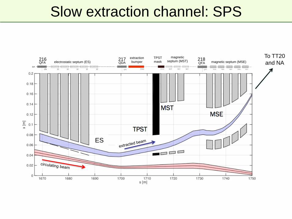
216 217 218electrostatic septum (ES)QFA QDA
magnetic
septum (MST) magnetic septum (MSE)QFA
TPST
maskextraction
bumper
To TT20
and NA
ES
Slow extraction channel SPS
Second-order resonant extraction
bull An extraction can also be made over a few hundred turns
bull 2nd and 4th order resonances
ndash Octupole fields distort the regular phase space particle trajectories
ndash Stable area defined delimited by two unstable Fixed Points
ndash Beam tune brought across a 2nd order resonance (Q rarr 05)
ndash Particle amplitudes quickly grow and beam is extracted in a few
hundred turns
Resonant extraction separatrices
bull Amplitude growth for 2nd order resonance much faster than 3rd ndash shorter
spills (asympmilliseconds vs seconds)
bull Used where intense pulses are required on target ndash eg neutrino production
X
X 3rd order resonant extraction 2nd order resonant extraction
Terminating
Resistor
Transmission
Line
Z
Kicker
Magnet
Z
Z
Main
Switch
PFN or
PFL
Z
RCPS
Dump
Switch
Dump
ResistorZ
Single-way Delay τp
Simplified kicker system schematic
Terminating
Resistor
Transmission
Line
Z
Kicker
Magnet
Z
Z
Main
Switch
PFN or
PFL
Z
RCPS
Dump
Switch
Dump
ResistorZ
Single-way Delay τp
V
distancet pvp
bull Pulse forming network or line (PFLPFN) charged to voltage V0 by the
resonant charging power supply (RCPS)
ndash RCPS is de-coupled from the system through a diode stack
t = 0
V0
ttime
int
kicker
field
t fill
Terminating
Resistor
Transmission
Line
Z
Kicker
Magnet
Z
Z
Main
Switch
PFN or
PFL
Z
RCPS
Dump
Switch
Dump
ResistorZ
Single-way Delay τp
Simplified kicker system schematic
Terminating
Resistor
Transmission
Line
Z
Kicker
Magnet
Z
Z
Main
Switch
PFN or
PFL
Z
RCPS
Dump
Switch
Dump
ResistorZ
Single-way Delay τp
t raquo 0
distance
bull Pulse forming network or line (PFLPFN) charged to voltage V0 by the
resonant charging power supply (RCPS)
ndash RCPS is de-coupled from the system through a diode stack
bull At t = 0 main switch is closed and current starts to flow into the kicker
I =V0
2Z
V
t pvp
V0
ttime
int
kicker
field
t fill
Terminating
Resistor
Transmission
Line
Z
Kicker
Magnet
Z
Z
Main
Switch
PFN or
PFL
Z
RCPS
Dump
Switch
Dump
ResistorZ
Single-way Delay τp
Simplified kicker system schematic
Terminating
Resistor
Transmission
Line
Z
Kicker
Magnet
Z
Z
Main
Switch
PFN or
PFL
Z
RCPS
Dump
Switch
Dump
ResistorZ
Single-way Delay τp
t raquo t fill
distance
bull At t = fill the voltage pulse of magnitude V02 has propagated through
the kicker and nominal field achieved with a current V02Z
ndash typically p gtgt fill (schematic for illustration purposes)
V0
2
V
t pvp
V0
I =V0
2Z
ttimet fill
t fill
int
kicker
field
Terminating
Resistor
Transmission
Line
Z
Kicker
Magnet
Z
Z
Main
Switch
PFN or
PFL
Z
RCPS
Dump
Switch
Dump
ResistorZ
Single-way Delay τp
Simplified kicker system schematic
Terminating
Resistor
Transmission
Line
Z
Kicker
Magnet
Z
Z
Main
Switch
PFN or
PFL
Z
RCPS
Dump
Switch
Dump
ResistorZ
Single-way Delay τp
t raquo t p
distance
bull PFN continues to discharge energy into kicker magnet and matched
terminating resistor
V0
2
V
t pvp
V0
I =V0
2Z
ttimet fill t p
I =V0
2Z
t fill
int
kicker
field
Terminating
Resistor
Transmission
Line
Z
Kicker
Magnet
Z
Z
Main
Switch
PFN or
PFL
Z
RCPS
Dump
Switch
Dump
ResistorZ
Single-way Delay τp
Simplified kicker system schematic
Terminating
Resistor
Transmission
Line
Z
Kicker
Magnet
Z
Z
Main
Switch
PFN or
PFL
Z
RCPS
Dump
Switch
Dump
ResistorZ
Single-way Delay τp
t raquo t p
distance
bull PFN continues to discharge energy into kicker magnet and matched
terminating resistor
bull At t asymp p the negative pulse reflects off the open end of the circuit
(dump switch) and back towards the kicker
V0
2
V
t pvp
V0
I =V0
2Z
ttimet fill t p
I =V0
2Z
t fill
int
kicker
field
Terminating
Resistor
Transmission
Line
Z
Kicker
Magnet
Z
Z
Main
Switch
PFN or
PFL
Z
RCPS
Dump
Switch
Dump
ResistorZ
Single-way Delay τp
Simplified kicker system schematic
Terminating
Resistor
Transmission
Line
Z
Kicker
Magnet
Z
Z
Main
Switch
PFN or
PFL
Z
RCPS
Dump
Switch
Dump
ResistorZ
Single-way Delay τp
t raquo t p
distance
V0
2
V
t pvp
I =V0
2Z
V0
bull PFN continues to discharge energy into matched terminating resistor
bull At t asymp p the negative pulse reflects off the open end of the circuit and
back towards the kicker
ttimet fill t p
I =V0
2Z
t fill
int
kicker
field
Terminating
Resistor
Transmission
Line
Z
Kicker
Magnet
Z
Z
Main
Switch
PFN or
PFL
Z
RCPS
Dump
Switch
Dump
ResistorZ
Single-way Delay τp
Simplified kicker system schematic
Terminating
Resistor
Transmission
Line
Z
Kicker
Magnet
Z
Z
Main
Switch
PFN or
PFL
Z
RCPS
Dump
Switch
Dump
ResistorZ
Single-way Delay τp
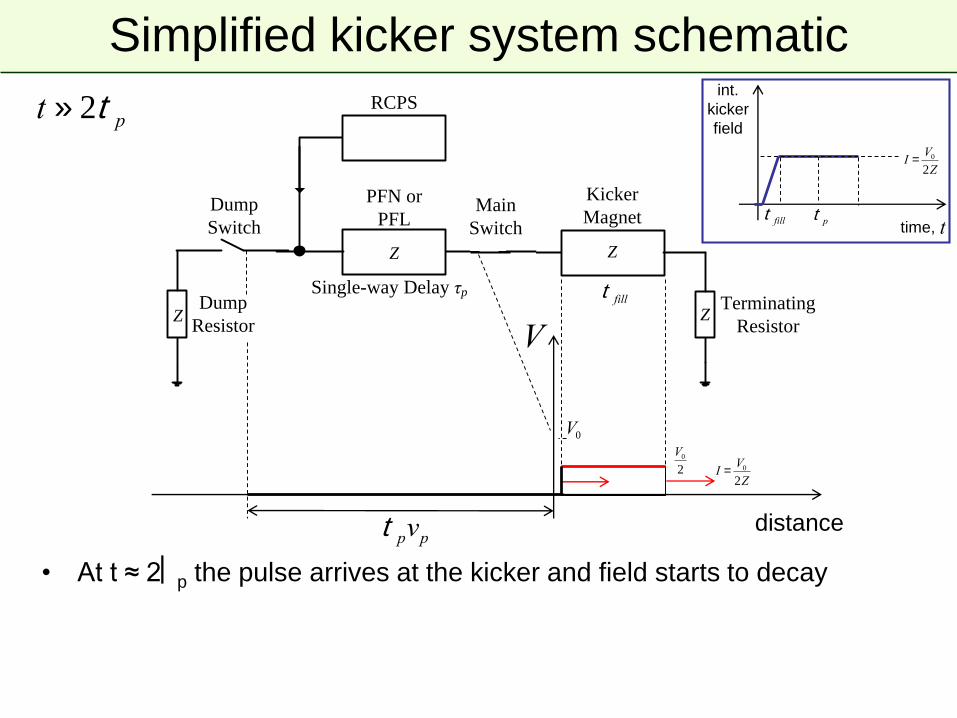
t raquo 2t p
distance
V0
2
V
t pvp
I =V0
2Z
V0
bull At t asymp 2p the pulse arrives at the kicker and field starts to decay
ttimet fill t p
I =V0
2Z
t fill
int
kicker
field
Terminating
Resistor
Transmission
Line
Z
Kicker
Magnet
Z
Z
Main
Switch
PFN or
PFL
Z
RCPS
Dump
Switch
Dump
ResistorZ
Single-way Delay τp
Simplified kicker system schematic
Terminating
Resistor
Transmission
Line
Z
Kicker
Magnet
Z
Z
Main
Switch
PFN or
PFL
Z
RCPS
Dump
Switch
Dump
ResistorZ
Single-way Delay τp
t = 2t p +t fill
distance
V
t pvp
ttime
V0
bull A kicker pulse of approximately 2p is imparted on the beam and all
energy has been emptied into the terminating resistor
2t p
t fill t p t fill
I =V0
2Z
t fill
int
kicker
field
Terminating
Resistor
Transmission
Line
Z
Kicker
Magnet
Z
Z
Main
Switch
PFN or
PFL
Z
RCPS
Dump
Switch
Dump
ResistorZ
Single-way Delay τp
Simplified kicker system schematic
Terminating
Resistor
Transmission
Line
Z
Kicker
Magnet
Z
Z
Main
Switch
PFN or
PFL
Z
RCPS
Dump
Switch
Dump
ResistorZ
Single-way Delay τp
t raquo 2t p
distance
V
t pvp
ttime
V0
bull Kicker pulse length can be changed by adjusting the relative timing of
dump and main switches
ndash eg if the dump and main switches are fired simultaneously the pulse
length will be halved and energy shared on dump and terminating resistors
2t p
t fill t p
I =V0
2Z
t fill
t fill
int
kicker
field

bull An accelerator has limited
dynamic range
bull Chain of stages needed to
reach high energy
bull Periodic re-filling of
storage rings like LHC
bull External facilities and
experiments
ndash eg ISOLDE
HIRADMAT AWAKEhellip
Beam transfer (into out of and
between machines) is necessary
Injection and extraction
CERN Accelerator Complex
Basics injection septum and kicker
Septum magnet
Kicker magnet
bull Kickers produce fast pulses rising their field within the particle-free gap in the
circulating beam (temporal separation)
bull Septa compensate for the relatively low kicker strength and approach closely
the circulating beam (spatial separation)
F-quad
t
kicker field
intensity injected
beam
Circulating beam
D-quad
bull Kicker bull Septum
hellipso we also call them
ldquoFast Pulsed Magnetsrdquo
Kickers - Magnetic parameters
B
HV conductor
Vertical aperture Vap
Ferrite
HV
By
m0
N times I
Vap
aelig
egrave
ccedilccedil
ouml
oslash
dividedivide
Return conductor
Horizontal
aperture Hap
Magnetic field
Derivation remember Ampegraverersquos Law
Lmag m
m0
N 2 timesHap
Vap
aelig
egrave
ccedilccedil
ouml
oslash
dividedivide
Magnet inductance
[per unit length]
Derivation remember Faradayrsquos Law
andFB = V dtograve
bull Dimensions Hap and Vap specified by beam parameters at kicker location
bull Ferrite (permeability μr asymp 1000) reinforces magnetic circuit and field uniformity in the gap
bull For fast rise-times the inductance must be minimised typically the number of turns N = 1
bull Kickers are often split into several magnet units powered independently
μr
μ0
V = LdI dt
A C-core geometry
commonly used at CERN
Pulsed magnet with very fast rise time (lt100 ns ndash few μs)
Magnetic
Septum coil 2 ndash 20 mm
Electrostatic
Thin wire or coil ~01 mm
Magnetic and electrostatic septum
E = V g
Typically V = 200 kV
E = 100 kVcm
E0 E=0
High voltage
electrodeHollow earth
electrode
Thin wire or
foil
g
Soft iron
Laminated yoke
Return coilSeptum coil
B0B=0
circulating
beam
circulating
beam
Bo = μ0I g
Typically I 5 - 25 kA
Single-turn injection ndash same plane
Septum magnet
Kicker magnet
bull Septum deflects the beam onto the closed orbit at the centre of the kicker
bull Kicker compensates for the remaining angle
bull Septum and kicker either side of D quad to minimise kicker strength
F-quad
t
kicker field
intensity injected
beam
lsquoboxcarrsquo stacking
Circulating beam
D-quad
Normalised phase space
bull Transform real transverse coordinates (x xrsquo s) to normalised co-ordinates
( ) where the independent variable becomes the phase advance μ
x(s) = e b(s) cos m(s)+m0[ ] m(s) =ds
b(s )0
s
ograve
X X m
Normalised phase space
1
x(s)
xrsquo(s)
1maxx
maxx
Area = p
maxX
maxX
Area = p
22 2 xxxx 22 XX
Real phase space Normalised phase space
Dm
- ea
b Dm =ds
b(s )S1
S2
ograve
Single-turn injectionNormalised phase space at centre of idealised septum
X
X
Single-turn injection
septum
Normalised phase space at centre of idealised septum
X
X
Single-turn injection
μ2 phase advance to kicker location
X
X
Single-turn injection
Kicker deflection places beam on central orbit
X
X
Normalised phase space at centre of idealised kicker
kicker
Injection oscillations
X
X
kicker - Δ
For imperfect injection the beam oscillates around the central orbit
eg kick error Δ
Injection oscillations
X
X
After 1 turnhellip
For imperfect injection the beam oscillates around the central orbit
eg kick error Δ
Injection oscillations
X
X
After 2 turnshellip
For imperfect injection the beam oscillates around the central orbit
eg kick error Δ
Injection oscillations
X
X
After 3 turns etchellip
For imperfect injection the beam oscillates around the central orbit
eg kick error Δ
Injection oscillations
bull Betatron oscillations with respect to the Closed Orbit
Transfer line LHC (first turn)
Horizontal
Vertical
bull Angular errors from septa and kicker have different orbit pattern
bull Correct the difference between injected beam and closed orbit
or 1st and 2nd turn
Filamentation
bull Non-linear effects (eg higher-order field components) introduce
amplitude-dependent effects into particle motion
bull Over many turns a phase-space oscillation is transformed into an
emittance increase
bull So any residual transverse oscillation will lead to an emittance blow-up
through filamentation
ndash ldquoTransverse damperrdquo systems are used to damp injection oscillations -
bunch position measured by a pick-up which is linked to a kicker
ndash Chromaticity coupled with a non-zero momentum spread at injection can
also cause filmentation often termed chromatic decoherence
bull See appendix for derivation of the emittance increase
X
X
Filamentation
X
X
Filamentation
X
X
Filamentation
X
X
Filamentation
X
X
Filamentation
X
X
Filamentation
X
X
Filamentation
X
X
Filamentation
X
X
Filamentation
X
X
Filamentation
bull Residual transverse oscillations lead to an effective emittance blow-
up through filamentation
bull Due to tune spread and energy spread the oscillation will not be
seen for long on a BPM signal
Inje
ctio
n o
scill
ation
Reference closed orbit
Filamentation - Decoherence
Multi-turn injection
bull For hadrons the beam density at injection can be limited either by
space charge effects or by the injector capacity
bull If we cannot increase charge density we can sometimes fill the
horizontal phase space to increase overall injected intensity
ndash Cannot inject into same phase space area as we would kick out the
beam located there
ndash If the acceptance of the receiving machine is larger than the delivered
beam emittance we can accumulate intensity
Multi-turn injection for hadrons
Septum magnet
bull No kicker but fast programmable bumpers
bull Bump amplitude decreases and a new batch injected turn-by-turn
bull Phase-space ldquopaintingrdquo
Programmable closed orbit bump
Circulating beam
1
Turn 1
Septum
X
X
Example CERN PSB injection high intensity beams fractional tune Qh asymp 025
Beam rotates π2 per turn in phase space
On each turn inject a new batch and reduce the bump amplitude
Multi-turn injection for hadrons
1
2
Turn 2
X
X
Septum
Multi-turn injection for hadrons
Example CERN PSB injection high intensity beams fractional tune Qh asymp 025
Beam rotates π2 per turn in phase space
3
2
1
Turn 3
X
X
Septum
Multi-turn injection for hadrons
Example CERN PSB injection high intensity beams fractional tune Qh asymp 025
Beam rotates π2 per turn in phase space
4
1
2
3
Turn 4
X
X
Septum
Multi-turn injection for hadrons
Example CERN PSB injection high intensity beams fractional tune Qh asymp 025
Beam rotates π2 per turn in phase space
3
2
4
51
Turn 5
X
X
Septum
Multi-turn injection for hadrons
Example CERN PSB injection high intensity beams fractional tune Qh asymp 025
Beam rotates π2 per turn in phase space
6
5
4
3
2
1
Turn 6
X
X
Septum
Multi-turn injection for hadrons
Example CERN PSB injection high intensity beams fractional tune Qh asymp 025
Beam rotates π2 per turn in phase space
7
6
5
4
3
2
1
Turn 7
X
X
Septum
Multi-turn injection for hadrons
Example CERN PSB injection high intensity beams fractional tune Qh asymp 025
Beam rotates π2 per turn in phase space
7
6
5
4
3
21
8
Turn 8
X
X
Septum
Multi-turn injection for hadrons
Example CERN PSB injection high intensity beams fractional tune Qh asymp 025
Beam rotates π2 per turn in phase space
7
6
5
4
3
2
1
8
9
Turn 9
X
X
Septum
Multi-turn injection for hadrons
Example CERN PSB injection high intensity beams fractional tune Qh asymp 025
Beam rotates π2 per turn in phase space
7
6
5
4
3
2
1
8
9
10
Turn 10
X
X
Septum
Multi-turn injection for hadrons
Example CERN PSB injection high intensity beams fractional tune Qh asymp 025
Beam rotates π2 per turn in phase space
7
6
5
4
3
2
1
8
9
10
11
Turn 11
X
X
Septum
Multi-turn injection for hadrons
Example CERN PSB injection high intensity beams fractional tune Qh asymp 025
Beam rotates π2 per turn in phase space
7
6
5
4
3
21
8
9
10
11
Turn 12
X
X
Septum
Multi-turn injection for hadrons
Example CERN PSB injection high intensity beams fractional tune Qh asymp 025
Beam rotates π2 per turn in phase space
7
6
5
4
3
2
1
8
9
10
11
Turn 13
X
X
Septum
Multi-turn injection for hadrons
Example CERN PSB injection high intensity beams fractional tune Qh asymp 025
Beam rotates π2 per turn in phase space
7
6
5
4
3
2
1
8
9
10
11
Turn 14
X
X
Septum
Multi-turn injection for hadrons
Example CERN PSB injection high intensity beams fractional tune Qh asymp 025
Beam rotates π2 per turn in phase space
7
6
5
4
3
2
1
8
9
10
11
Turn 15
In reality filamentation (often space-charge driven) occurs to produce a quasi-
uniform beam
X
X
Phase space has been ldquopaintedrdquo
Multi-turn injection for hadrons
Charge exchange H- injection
bull Multi-turn injection is essential to accumulate high intensity
bull Disadvantages inherent in using an injection septum
ndash Width of several mm reduces aperture
ndash Beam losses from circulating beam hitting septum
bull typically 30 ndash 40 for the CERN PSB injection at 50 MeV
ndash Limits number of injected turns to 10 ndash 20
bull Charge-exchange injection provides elegant alternative
ndash Possible to ldquocheatrdquo Liouvillersquos theorem which says that emittance is
conservedhellip
ndash Convert H- to p+ using a thin stripping foil allowing injection into the
same phase space area
Charge exchange H- injection
Injection chicane dipoles
Circulating p+
Stripping foil
H0
Circulating p+
Start of injection process
Charge exchange H- injection
Circulating p+
Stripping foil
End of injection process with painting
H0
Injection chicane dipoles
Displace orbit
Circulating p+
Accumulation process on foil
V Forte Performance of the CERN PSB at 160 MeV with H- charge exchange injection PhD thesis ndash CERN and Universiteacute Blaise Pascal
bull Linac4 connection to the PS booster at 160 MeV
ndash H- stripped to p+ with an estimated efficiency asymp98 with C foil 200 μgcm-2
Charge exchange H- injection
bull Paint uniform transverse phase space density by modifying closed
orbit bump and steering injected beam
bull Foil thickness calculated to double-strip most ions (asymp99)
ndash 50 MeV ndash 50 μgcm-2
ndash 800 MeV ndash 200 μgcm-2 (asymp 1 μm of C)
bull Carbon foils generally used ndash very fragile
bull Injection chicane reduced or switched off after injection to avoid
excessive foil heating and beam blow-up
bull Longitudinal phase space can also be painted turn-by-turn
ndash Variation of the injected beam energy turn-by-turn (linac voltage scaled)
ndash Chopper system in linac to match length of injected batch to bucket
H- injection - painting
Timexrsquo vs x yrsquo vs y y vs x
Note injection into
same phase
space area as
circulating beam
asymp100 turns
Lepton injection
bull Single-turn injection can be used as for hadrons however lepton
motion is strongly damped (different with respect to proton or ion
injection)
ndash Synchrotron radiation
bull see Electron Beam Dynamics lectures by L Rivkin
bull Can use transverse or longitudinal damping
ndash Transverse - Betatron accumulation
ndash Longitudinal - Synchrotron accumulation (2 x faster than transverse)
Betatron lepton injection
bull Beam is injected with an angle with respect to the closed orbit
bull Injected beam performs damped betatron oscillations about the closed orbit
Septum magnet
Closed orbit bumpers or kickers
Circulating
beam
Betatron lepton injection
Injected bunch performs damped betatron oscillations
In LEP at 20 GeV the damping time was about 6rsquo000 turns (06 seconds)
X
X
Synchrotron lepton injection
Septum magnet
bull Beam injected parallel to circulating beam onto dispersion orbit of a
particle having the same momentum offset Δpp
bull Injected beam makes damped synchrotron oscillations at Qs but does
not perform betatron oscillations
Closed orbit bumpers or kickersxs = Dx Δpp0
xsp = p0
p = p0 + Δp
Inject an off-momentum beam
at a location with dispersion
Synchrotron lepton injection
F
E
Double batch injection possiblehellip
Longitudinal damping time in LEP was ~3rsquo000 turns (2x faster than transverse)
Injection 1 (turn N)
Injection 2 (turn N + Qs2)
Stored beam
RF bucket
Synchrotron lepton injection in LEP
Synchrotron injection in LEP gave improved background for LEP experiments
due to small orbit offsets in zero dispersion straight sections
Injection - summary
bull Several different techniques using kickers septa and bumpers
ndash Single-turn injection for hadrons
bull Boxcar stacking transfer between machines in accelerator chain
bull Angle position errors injection oscillations
bull Uncorrected errors filamentation emittance increase
ndash Multi-turn injection for hadrons
bull Phase space painting to increase intensity
bull H- injection allows injection into same phase space area
ndash Lepton injection take advantage of damping
bull Less concerned about injection precision and matching
Extraction
bull Different extraction techniques exist depending on requirements
ndash Fast extraction le1 turn
ndash Non-resonant (fast) multi-turn extraction few turns
ndash Resonant low-loss (fast) multi-turn extraction few turns
ndash Resonant multi-turn extraction many thousands of turns
bull Usually higher energy than injection stronger elements (intBdl)
ndash At high energies many kicker and septum modules may be required
ndash To reduce kicker and septum strength beam can be moved near to
septum by closed orbit bump
ndash Beam size scales with 1 120574 =gt smaller than injection
Fast single turn extraction
Septum magnet
Kicker magnet
bull Bumpers move circulating beam close to septum to reduce kicker strength
bull Kicker deflects the entire beam into the septum in a single turn
bull Most efficient (lowest deflection angles required) for π2 phase advance
between kicker and septum
Closed orbit bumpers
Entire beam kicked into septum gap and extracted over a single turn
F-quad D-quad
Circulating
beam
t
kicker field
intensity
Fast single turn extraction
bull For transfer of beams between accelerators in an injector chain
bull For secondary particle production
ndash eg neutrinos radioactive beams
bull Losses from transverse scraping or from particles in extraction gap
ndash Fast extraction from SPS to CNGS
1E+08
1E+09
1E+10
1E+11
0 1 2 3 4 5 6 7 8 9 10 11 12 13 14 15time us
p+
00
02
04
06
08
10
12 kk
o
Intensity [10^9 p25ns]
Kicker strength
Particles in SPS extraction kicker rise- and fall-time gaps
Multi-turn extraction
bull Some filling schemes require a beam to be injected in several turns to
a larger machinehellip
bull And very commonly Fixed Target physics experiments and medical
accelerators often need a quasi-continuous flux of particleshellip
bull Multi-turn extractionhellip
ndash Fast Non-resonant and resonant multi-turn ejection (few turns) for filling
bull eg PS to SPS at CERN for high intensity proton beams (gt25 1013 protons)
ndash Slow Resonant extraction (ms to hours) for experiments
Extracted beamMagnetic
septum
bull Fast bumper deflects the whole beam onto the septum
bull Beam extracted in a few turns with the machine tune rotating the beam
bull Intrinsically a high-loss process thin septum essential
bull Often combine thin electrostatic septa with magnetic septa
Non-resonant multi-turn extraction
Fast closed orbit bumpers
Beam bumped to septum part of beam lsquoshavedrsquo off each turn
Electrostatic
septum
Non-resonant multi-turn extraction
bull Example system CERN PS to SPS Fixed-Target lsquocontinuous transferrsquo
ndash Accelerate beam in PS to 14 GeVc
ndash Empty PS machine (21 μs long) in 5 turns into SPS
ndash Do it again
ndash Fill SPS machine (11 x CPS 23 μs long)
ndash Quasi-continuous beam in SPS (2 x 1 μs gaps)
ndash Total intensity per PS extraction asymp 3 1013 p+
ndash Total intensity in SPS asymp 5 1013 p+
Extracted beam
beam
To the SPS
The PS
Non-resonant multi-turn extraction
X
X
CERN PS to SPS 5-turn continuous transfer ndash 1st turn
Qh = 025
1 2 3 4 5
Bump vs turn
1
2
3
4
5
septum
Non-resonant multi-turn extraction
X
X
CERN PS to SPS 5-turn continuous transfer ndash 2nd turn
Qh = 025
1 2 3 4 5
Bump vs turn
1
2
3
4 5
septum
Non-resonant multi-turn extraction
X
X
CERN PS to SPS 5-turn continuous transfer ndash 3rd turn
Qh = 025
1 2 3 4 5
Bump vs turn
septum
1
2
3
4
5
Non-resonant multi-turn extraction
X
X
CERN PS to SPS 5-turn continuous transfer ndash 4th turn
Qh = 025
1 2 3 4 5
Bump vs turn
septum
1
2
3
45
Non-resonant multi-turn extraction
X
X
CERN PS to SPS 5-turn continuous transfer ndash 5th turn
Qh = 025
5
1 2 3 4 5
Bump vs turn
Non-resonant multi-turn extraction
bull CERN PS to SPS 5-turn continuous transfer
ndash Losses impose thin septumhellip
hellip an electrostatic septum is needed in addition to the magnetic septum
ndash Still about 15 of beam lost in PS-SPS CT
ndash Difficult to get equal intensities per turn
ndash Different trajectories for each turn
ndash Different emittances for each turn
X
X
1
X
X
2
X
X
3
X
X
4
X
X
5
I
1 2 3 4 5
Resonant multi-turn (fast) extraction
bull Adiabatic capture of beam in stable ldquoislandsrdquo
- Use non-linear fields (sextupoles and octupoles) to create islands of
stability in phase space
- A slow (adiabatic) tune variation to cross a resonance and to drive
particles into the islands (capture) with the help of transverse excitation
(using damper)
- Variation of field strengths to separate the islands in phase space
bull Several big advantages
ndash Losses reduced significantly (no particles at the septum in transverse
plane)
ndash Phase space matching improved with respect to existing non-resonant
multi-turn extraction - lsquobeamletsrsquo have similar emittance and optical
parameters
Resonant multi-turn (fast) extraction
a Unperturbed beam
b Increasing non-linear
fields
a Beam captured in
stable islands
b Islands separated and
beam bumped across
septum ndash extracted in
5 turns
(see Non-Linear Beam Dynamics lectures
by Y Papaphilippou)
Courtesy M Giovannozzi MTE Design Report CERN-2006-011 2006
Resonant multi-turn (fast) extraction
Septum wire
1 2 3 4 5
Bump vs turn
Qh = 025
a Unperturbed beam
b Increasing non-linear
fields
a Beam captured in
stable islands
b Islands separated and
beam bumped across
septum ndash extracted in
5 turns
Courtesy M Giovannozzi MTE Design Report CERN-2006-011 2006
Extracted beam
bull Slow bumpers move the beam near the septum
bull Tune adjusted close to nth order betatron resonance
bull Multipole magnets excited to define stable area in phase space size
depends on ΔQ = Q - Qr
Resonant multi-turn (slow) extraction
Closed orbit bumpers
Non-linear fields excite resonances that drive the beam slowly across the septum
Magnetic
septum
Electrostatic
septum
Resonant multi-turn (slow) extraction
bull 3rd order resonances ndash see lectures by Y Papaphilippou
ndash Sextupole fields distort the circular normalised phase space particle trajectories
ndash Stable area defined delimited by unstable Fixed Points
ndash Sextupole magnets arranged to produce suitable phase space orientation of the stable triangle at thin electrostatic septum
ndash Stable area can be reduced byhellip
bull Increasing the sextupole strength orhellip
bull Fixing the sextupole strength and scanning the machine tune Qh (and therefore the resonance) through the tune spread of the beam
bull Large tune spread created with RF gymnastics (large momentum spread) and large chromaticity
2
21 1
kQR fp
Rfp
Third-order resonant extraction
bull Particles distributed on emittance contours
bull ΔQ large ndash no phase space distortion
X
X
Septum wire
Third-order resonant extraction
bull Sextupole magnets produce a triangular stable area in phase space
bull ΔQ decreasing ndash phase space distortion for largest amplitudes
X
X
Septum wire
Third-order resonant extraction
X
X
Septum wire
bull Sextupole magnets produce a triangular stable area in phase space
bull ΔQ decreasing ndash phase space distortion for largest amplitudes
Third-order resonant extraction
X
X
Septum wire
bull Sextupole magnets produce a triangular stable area in phase space
bull ΔQ decreasing ndash phase space distortion for largest amplitudes
Third-order resonant extraction
X
X
Septum wire
bull Sextupole magnets produce a triangular stable area in phase space
bull ΔQ decreasing ndash phase space distortion for largest amplitudes
Third-order resonant extraction
bull Largest amplitude particle trajectories are significantly distorted
bull Locations of fixed points noticeable at extremities of phase space triangle
X
X
Septum wire
Third-order resonant extraction
X
X
Septum wire
bull ΔQ small enough that largest amplitude particle trajectories are unstable
bull Unstable particles follow separatrix branches as they increase in amplitude
Third-order resonant extraction
X
X
Septum wire
bull Stable area shrinks as ΔQ becomes smaller
Third-order resonant extraction
X
X
Septum wire
bull Separatrix position in phase space shifts as the stable area shrinks
Third-order resonant extraction
bull As the stable area shrinks the circulating beam intensity drops since
particles are being continuously extracted
X
X
Septum wire
Third-order resonant extraction
X
X
Septum wire
bull As the stable area shrinks the circulating beam intensity drops since
particles are being continuously extracted
Third-order resonant extraction
X
X
Septum wire
bull As the stable area shrinks the circulating beam intensity drops since
particles are being continuously extracted
Third-order resonant extraction
X
X
Septum wire
bull As the stable area shrinks the circulating beam intensity drops since
particles are being continuously extracted
Third-order resonant extraction
X
X
Septum wire
bull As ΔQ approaches zero the particles with very small amplitude are
extracted
Slow extracted spill quality
Reducing Q with main machine quadrupoles can be augmented with a
lsquoservorsquo quadrupole which can modulate Q in a servo loop acting on
a measurement of the spill intensity
50 Hz
10 Hz
An example of a spill at SPS to the North Area with large n x 50 Hz
components and another noise source at 10 Hz
bull The slow-extraction is a resonant process and it amplifies the smallest
imperfections in the machine- eg spill intensity variations can be explained by ripples in the current of the
quads (mains n x 50 Hz) at the level of a few ppm
- Injection of n x 50 Hz signals in counter-phase on dedicated quads can be
used to compensate
Extraction - summary
bull Several different techniques
ndash Single-turn fast extraction
bull for transfer between machines in accelerator chain beam abort etc
ndash Non-resonant (fast) multi-turn extraction
bull slice beam into equal parts for transfer between machine over a few turns
ndash Resonant low-loss (fast) multi-turn extraction
bull create stable islands in phase space slice off over a few turns
ndash Resonant (slow) multi-turn extraction
bull create stable area in phase space slowly drive particles into resonance long spill over many thousand turns
1 Extract a beam out of one machine initial beam parameters
2 Transport this beam towards the following machine (or experiment)
3 Inject this beam into a following machine with a predefined optics
Transfer line optics has to produce required beam parameters for matching
Linking Machines
Extraction
Transfer
Injection
s
(αx βx Dx Drsquoxαy βy Dy Drsquoy)1 M12
(αx βx Dx Drsquoxαy βy Dy Drsquoy)2
Linking Machines
bull Beams have to be transported from extraction of one machine to
injection of the next machine
- Trajectory must be matched in all 6 geometric degrees of freedom
(xyzθΦψ)
bull Linking the optics is a complicated process
- Parameters at start of line have to be propagated to matched parameters
at the end of the line (injection to another machine fixed target etc )
- Need to ldquomatchrdquo 8 variables (αx βx Dx Drsquox and αy βy Dy Drsquoy)
- Done with number of independently power (ldquomatchingrdquo) quadrupoles
- Maximum β and D values are imposed by magnetic apertures
- Other constraints exist
- Phase conditions for collimators
- Insertions for special equipment like stripping foils
- hellip
bull Matching with computer codes and relying on mixture of theory experience
intuition trial and error
Optics Matching example
0
50
100
150
200
250
300
0 250 500 750 1000 1250 1500 1750 2000 2250 2500 2750 3000 3250 3500 3750 4000
S [m]
[
m]
BETXBETY
SPS LHCRegular lattice (FODO)
(elements all powered in series
with same strengths)
Final matching
section
SPS to LHC Transfer Line (3 km)Extraction
point Injection
point
Initial matching
section
Independently powered (tuneable) quadrupoles
Independently powered (tuneable) quadrupoles and (in this case) passive
protection devices
Need to match 8 variables (TWISS parameters) for propagation from start to end of a transfer
Optical Mismatch at Injection
bull Filamentation fills larger ellipse with same shape as matched ellipse
x
xrsquo
Turn 0
Turn N
Time
bull Dispersion mismatch at injection will also cause emittance blow-up
Further reading and references
bull Lots of resources presented at the recent Specialised CAS School
bull Beam Injection Extraction and Transfer 10-19 March 2017 Erice Italy
bull httpscaswebcernchschoolserice-2017
Terminating
Resistor
Transmission
Line
Z
Kicker
Magnet
Z
Z
Main
Switch
PFN or
PFL
Z
RCPS
Dump
Switch
Dump
ResistorZ
Single-way Delay τp
Simplified kicker system schematic
Terminating
Resistor
Transmission
Line
Z
Kicker
Magnet
Z
Z
Main
Switch
PFN or
PFL
Z
RCPS
Dump
Switch
Dump
ResistorZ
Single-way Delay τp
bull Main sub-systems (ldquocomponentsrdquo) of kicker system
ndash RCPS = Resonant Charging Power Supply
ndash PFL = Pulse Forming Line (coaxial cable) or PFN = Pulse Forming
Network (lumped elements)
ndash Fast high power switch(es)
ndash Transmission line(s) coaxial cable(s)
ndash Kicker Magnet
ndash Terminators (resistive)
Matched impedance example
Terminating
Resistor
Transmission
Line
Z
Kicker
Magnet
Z
Z
Main
Switch
PFN or
PFL
Z
RCPS
Dump
Switch
Dump
ResistorZ
Single-way Delay τp
Simplified kicker system schematic
Terminating
Resistor
Transmission
Line
Z
Kicker
Magnet
Z
Z
Main
Switch
PFN or
PFL
Z
RCPS
Dump
Switch
Dump
ResistorZ
Single-way Delay τp
bull PFLPFN charged to voltage V0 by the RCPS
bull Main switch is closedhellip
hellipvoltage pulse of V02 flows through kicker
bull Once the pulse reaches the (matched) terminating resistor full-field has
been established in the kicker magnet
bull Pulse length controlled between t = 0 and 2p with dump switch
Matched impedance example
PFLPFN
Pulse Forming Line (PFL)
bull Low-loss coaxial cable
bull Fast and ripple-free pulses
bull Attenuation (droop ~1) becomes
problematic for pulses gt 3 μs
bull Above 50 kV SF6 pressurized PE
tape cables are used
bull Bulky 3 μs pulse ~ 300 m of cable
Pulse Forming Network (PFN)
bull Artificial coaxial cable made of lumped
elements
bull For low droop and long pulses gt 3 μs
bull Each cell individually adjustable
adjustment of pulse flat-top difficult
and time consuming
Reels of PFL used at the PS complex (as old as the photograph) SPS extraction kicker (MKE) PFN (17 cells)
Power semiconductor switches
bull Suitable for scenarios where erratic
turn-on is not allowed
bull For example LHC beam dump
kickers held at nominal voltage
throughout operation (gt10h) ready to
fire and safely abort at any moment
bull Hold off up to 30 kV and switch up to
18 kA
bull Slower switching gt 1 μs (~18kAμs)
bull Low maintenance
Switches
~ 3
40 m
m
Thyratrons
bull Deuterium gas thyratrons are commonly used
bull Hold off 80 kV and switch up to 6 kA
bull Fast switching ~ 30 ns (~150 kAμs)
bull Erratic turn-on use with RCPS to reduce hold-off time
ThyratronStack of high-power semiconductor
switches (GTOs)
Terminating
Resistor
Transmission
Line
Z
Kicker
Magnet
Z
Z
Main
Switch
PFN or
PFL
Z
RCPS
Dump
Switch
Dump
ResistorZ
Single-way Delay τp
Simplified kicker system schematic
Terminating
Resistor
Transmission
Line
Z
Kicker
Magnet
Z
Z
Main
Switch
PFN or
PFL
Z
RCPS
Dump
Switch
Dump
ResistorZ
Single-way Delay τp
V
distancet pvp
bull Pulse forming network or line (PFLPFN) charged to voltage V0 by the
resonant charging power supply (RCPS)
ndash RCPS is de-coupled from the system through a diode stack
t = 0
V0
ttime
int
kicker
field
t fill
Terminating
Resistor
Transmission
Line
Z
Kicker
Magnet
Z
Z
Main
Switch
PFN or
PFL
Z
RCPS
Dump
Switch
Dump
ResistorZ
Single-way Delay τp
Simplified kicker system schematic
Terminating
Resistor
Transmission
Line
Z
Kicker
Magnet
Z
Z
Main
Switch
PFN or
PFL
Z
RCPS
Dump
Switch
Dump
ResistorZ
Single-way Delay τp
t = 2t p +t fill
distance
V
t pvp
ttime
V0
bull A kicker pulse of approximately 2p is imparted on the beam and all
energy has been emptied into the terminating resistor
2t p
t fill t p t fill
I =V0
2Z
t fill
int
kicker
field
Terminating
Resistor
Transmission
Line
Z
Kicker
Magnet
Z
Z
Main
Switch
PFN or
PFL
Z
RCPS
Dump
Switch
Dump
ResistorZ
Single-way Delay τp
Simplified kicker system schematic
Terminating
Resistor
Transmission
Line
Z
Kicker
Magnet
Z
Z
Main
Switch
PFN or
PFL
Z
RCPS
Dump
Switch
Dump
ResistorZ
Single-way Delay τp
t raquo 2t p
distance
V
t pvp
ttime
V0
bull Kicker pulse length can be changed by adjusting the relative timing of
dump and main switches
ndash eg if the dump and main switches are fired simultaneously the pulse
length will be halved and energy shared on dump and terminating resistors
2t p
t fill t p
I =V0
2Z
t fill
t fill
int
kicker
field
Short circuit mode
bull Short-circuiting the termination offers twice the kick (for a given kicker magnet)
- Fill time of kicker magnet is doubled
- Diode as dump switch provides solution for fixed pulse length
Terminating
Resistor
Transmission
Line
Z
Kicker
Magnet
Z
Z
Main
Switch
PFN or
PFL
Z
RCPS
Dump
Switch
Dump
ResistorZ
Single-way Delay τpTerminating
Resistor
Transmission
Line
Z
Kicker
Magnet
Z
Z
Main
Switch
PFN or
PFL
Z
RCPS
Dump
Switch
Dump
ResistorZ
Single-way Delay τp
distance
Vt pvp
V0
Dump Diode
Short Circuit
-V0
2
ttime
t raquo 2(t p +t fill )
Boundary condition at
short-circuit
V = 0 doubling I
Diode conducts as voltage
flips sign and match dump
resistor absorbs energy
I =V0
Z
2(t p +t fill )
t fill
int
kicker
field
I- =V0
2Z
Kicker magnets ndash design options
bull Type ldquolumped inductancerdquo or ldquodistributed inductancerdquo (transmission line)
bull Other considerations
ndash Machine vacuum kicker in-vacuum or external
ndash Aperture geometry of ferrite core
ndash Termination matched impedance or short-circuit
VZ Lmag
From generator
(eg PFN)V
Z =Lcell
Ccell
bull simple magnet design
bull magnet must be nearby the
generator to minimise inductance
bull exponential field rise-time
bull slow rise-times ~ 1 μs
bull complicated magnet design
bull impedance matching important
bull field rise-time depends on propagation
time of pulse through magnet
bull fast rise-times ltlt 1 μs
Ccell
2
Ccell
2
Ccell
2
Ccell
2
Ccell
2
Ccell
2
Lcell Lcell Lcell
Cell 1hellip Cell n - 1 hellip Cell n
t = n Lcell timesCcell = nLcell
Z=Lmag
Z
I =V
Z(1- e-t t ) t =
Lmag
Z
Lmag = nLcellFrom generator
(eg PFN)
Magnets ndash transmission line
bull Todayrsquos fast (rise-times of lt few hundred ns) kicker magnets are generally
ferrite loaded transmission lines
ndash Ferrite C-cores are sandwiched between HV plates
ndash Grounded plates are interleaved to form a capacitor to ground
B
Ground plate
HV conductor
Return
conductor
Ferrite
HV
End Viewand so onhellip
beam
Side Viewcell
Magnets ndash transmission line
bull Todayrsquos fast (rise-times of lt few hundred ns) kicker magnets are generally
ferrite loaded transmission lines
ndash Kicker magnets consists of many relatively short cells to approximate a
broadband coaxial cable
LcLc
Cc2Cc2Cc2
Lc
Cc2Cc2
Lc
Cc2Cc2
0
Cc2
cell
1 2 (n-1) n
A real kickerhellip
Prototype for AGS
injection kicker upgrade
beam
and so onhellip
Side Viewcell
Electrostatic septum
bull Thin septum ~ 01 mm needed for high extraction efficiency
ndash Foils typically used
ndash Stretched wire arrays provide thinner septa and lower effective density
bull Challenges include conditioning and preparation of HV surfaces vacuum
in range of 10-9 ndash 10-12 mbar and in-vacuum precision position alignment
E
(up to 10 MVm
in UHV)
x
yz
d (typically 10 to 35 mm)
V (up to 300 kV)
circulating beam
extracted
beam
septum foil
(Mo or Z-Re)
electrode
(Al Ti SS)
support
Grounded support
Electrode (HV)Foil
Foil TensionersBake-out lamps for UHV
Electrostatic septum
bull At SPS we slow-extract 400 GeV protons using approximately 15 m of septum split into 5 separate vacuum tanks each over 3 m long
- Alignment of the 60 - 100 μm wire array over 15 m is challenging
DC direct drive magnetic septum
magnet yoke (laminated steel)septum
x
yz
Cooling
Electrical connectionsCirculating beam
vacuum
chamber
extracted
beam
0
B
x
x
septum
(typically 6 to 20 mm)
g
(typically
25 - 60 mm)
bull Continuously powered rarely under vacuum
bull Multi-turn coil to reduce current needed but cooling still an issue
ndash Cooling water circuits flow rate typically at 12 ndash 60 lmin
ndash Current can range from 05 to 4 kA and power consumption up to 100 kW
rear
conductor
B
septum
(typically 3 to 20 mm)
circulating
beamrear
conductor
septum
conductor
extracted
beam0
B
x
x
Direct drive pulsed magnetic septum
x
yz
Beam ldquomonitorrdquo
Beam screenBake-out lamps for UHV
Septumbull In vacuum to minimise distance between circulating and extracted beam
bull Single-turn coil to minimise inductance bake-out up to 200 degC (~10-9 mbar)
bull Pulsed by capacitor discharge (third harmonic flattens the pulse)
ndash Current in range 7 ndash 40 kA with a few ms oscillation period
ndash Cooling water circuits flow rate from 1 ndash 80 lmin
g
(typically
18 - 60 mm)
magnet yoke (laminated steel)
B
Appendix
Injection errors
kicker
bpm1 bpm2
phase m ~p2 ~p2~p2
septum
Angle errors
sk
Measured
Displacements
d12
s k
d1
d2
Dqk bk
At kicker location
Injection errors
kicker
bpm1 bpm2
phase m ~p2 ~p2~p2
septum
Angle errors
sk
Measured
Displacements
d12
d1 = s (s1) sin (m1 ndash ms) + k (k1) sin (m1 ndash mk)
asymp k (k1)
s k
d1
d2
Dqk bk
x
b1
raquo Dqk bk
At BPM1 location
d2 = s (s2) sin (m2 ndash ms) + k (k2) sin (m2 ndash mk)
asymp -s (s2)
Blow-up from steering error
X
X
Misinjected
beam
Matched
particles
L
A0
bull The new particle coordinates in normalised phase space are
Xerror = X0 +Lcosq
X error = X 0+Lsinq
bull For a general particle distribution
where Ai denotes amplitude in
normalised phase of particle i
bull The emittance of the distribution is
L = Da ematched
bull So we plug in the new coordinates
bull Taking the average over distribution
bull Giving the diluted emittance as
Blow-up from steering error
0
X
X
Effect of steering error on a given particle
Matched
particles
A
L
= (X0 +Lcosq)2 + (X 0+Lsinq)2
= X0
2 +X 02+2L(X0 cosq +X 0sinq)+L2
cos2q +sin2q =1
0
= 2ematched +L2
ediluted =ematched +L2
2
L = Da ematched
=ematched 1+Da2
2
eacute
eumlecirc
ugrave
ucircuacute
Blow-up from steering error
bull Consider a collection of particles with max amplitudes A
bull The beam can be injected with an error in angle and position
bull For an injection error Δa in units of σ = (βε) the mis-injected beam is
offset in normalised phase space by an amplitude L = Δaε
X
X
Misinjected
beam
Matched
particles
L
A
Blow-up from steering error
bull Consider a collection of particles with max amplitudes A
bull The beam can be injected with an error in angle and position
bull For an injection error Δa in units of σ = (βε) the mis-injected beam is
offset in normalised phase space by an amplitude L = Δaε
X
XMatched
particles
A
L
bull Any given point on the matched ellipse
is randomised over all phases after
filamentation due to the steering error
Effect of steering error on a given particle
Blow-up from steering error
bull Consider a collection of particles with max amplitudes A
bull The beam can be injected with an error in angle and position
bull For an injection error Δa in units of σ = (βε) the mis-injected beam is
offset in normalised phase space by an amplitude L = Δaε
X
XMatched
particles
A
L
bull Any given point on the matched ellipse
is randomised over all phases after
filamentation due to the steering error
bull For a general particle distribution
where Ai denotes amplitude in
normalised phase of particle i
Effect of steering error on a given particle
Blow-up from steering error
bull Consider a collection of particles with max amplitudes A
bull The beam can be injected with an error in angle and position
bull For an injection error Δa in units of σ = (βε) the mis-injected beam is
offset in normalised phase space by an amplitude L = Δaε
X
X
Effect of steering error on a given particle
Matched
particles
A
L
bull Any given point on the matched ellipse
is randomised over all phases after
filamentation due to the steering error
bull For a general particle distribution
where Ai denotes amplitude in
normalised phase of particle i
bull After filamentation
ediluted =ematched +L2
2
See appendix for derivation
bull A numerical examplehellip
bull Consider an offset Δa = 05σ for injected beam
bull For nominal LHC beam
hellipallowed growth through LHC cycle ~10
Blow-up from steering error
Misinjected beam
Matched
Beam
05
X
Xediluted =ematched +L2
2
L = Da ematched
=ematched 1+Da2
2
eacute
eumlecirc
ugrave
ucircuacute
=ematched 1125[ ]
Particle at turn 0
bull On resonance sextupole kicks add-up driving particles over septum
Third-order resonant extraction
Particle at turn 1
bull On resonance sextupole kicks add-up driving particles over septum
Third-order resonant extraction
Particle at turn 2
bull On resonance sextupole kicks add-up driving particles over septum
Third-order resonant extraction
Particle at turn 3
bull On resonance sextupole kicks add-up driving particles over septum
Third-order resonant extraction
bull On resonance sextupole kicks add-up driving particles over septum
ndash Distance travelled in these final three turns is termed the ldquospiral steprdquo ΔXES
ndash Extraction bump trimmed in the machine to adjust the spiral step
Extracted beam
Third-order resonant extraction
DXES micro k2
XES2
cosqDXES
XES
bull On resonance sextupole kicks add-up driving particles over septum
ndash Distance travelled in these final three turns is termed the ldquospiral steprdquo ΔXES
ndash Extraction bump trimmed in the machine to adjust the spiral step
bull RF gymnastics before extraction
Extracted beam
Third-order resonant extraction
DXES micro k2
XES2
cosqDXES
XES
Dp
pmicro-DQ
momentum spread tune
-30dBm
dBm-130
A Ch1 Spectrum 0 dBmRange
10 kHzSpan Center 110355665 GHz3820312 mSecTimeLen RBW 100 Hz
4375 Sec
7969 Sec
3578 Sec
Spill = 48 stim
e
Schottky measurement during spill courtesy of T Bohl
Δϕ = π
Δϕ = -π
small Δp
rotation large Δp
RF
off
RF gymn
216 217 218electrostatic septum (ES)QFA QDA
magnetic
septum (MST) magnetic septum (MSE)QFA
TPST
maskextraction
bumper
To TT20
and NA
ES
Slow extraction channel SPS
Second-order resonant extraction
bull An extraction can also be made over a few hundred turns
bull 2nd and 4th order resonances
ndash Octupole fields distort the regular phase space particle trajectories
ndash Stable area defined delimited by two unstable Fixed Points
ndash Beam tune brought across a 2nd order resonance (Q rarr 05)
ndash Particle amplitudes quickly grow and beam is extracted in a few
hundred turns
Resonant extraction separatrices
bull Amplitude growth for 2nd order resonance much faster than 3rd ndash shorter
spills (asympmilliseconds vs seconds)
bull Used where intense pulses are required on target ndash eg neutrino production
X
X 3rd order resonant extraction 2nd order resonant extraction
Terminating
Resistor
Transmission
Line
Z
Kicker
Magnet
Z
Z
Main
Switch
PFN or
PFL
Z
RCPS
Dump
Switch
Dump
ResistorZ
Single-way Delay τp
Simplified kicker system schematic
Terminating
Resistor
Transmission
Line
Z
Kicker
Magnet
Z
Z
Main
Switch
PFN or
PFL
Z
RCPS
Dump
Switch
Dump
ResistorZ
Single-way Delay τp
V
distancet pvp
bull Pulse forming network or line (PFLPFN) charged to voltage V0 by the
resonant charging power supply (RCPS)
ndash RCPS is de-coupled from the system through a diode stack
t = 0
V0
ttime
int
kicker
field
t fill
Terminating
Resistor
Transmission
Line
Z
Kicker
Magnet
Z
Z
Main
Switch
PFN or
PFL
Z
RCPS
Dump
Switch
Dump
ResistorZ
Single-way Delay τp
Simplified kicker system schematic
Terminating
Resistor
Transmission
Line
Z
Kicker
Magnet
Z
Z
Main
Switch
PFN or
PFL
Z
RCPS
Dump
Switch
Dump
ResistorZ
Single-way Delay τp
t raquo 0
distance
bull Pulse forming network or line (PFLPFN) charged to voltage V0 by the
resonant charging power supply (RCPS)
ndash RCPS is de-coupled from the system through a diode stack
bull At t = 0 main switch is closed and current starts to flow into the kicker
I =V0
2Z
V
t pvp
V0
ttime
int
kicker
field
t fill
Terminating
Resistor
Transmission
Line
Z
Kicker
Magnet
Z
Z
Main
Switch
PFN or
PFL
Z
RCPS
Dump
Switch
Dump
ResistorZ
Single-way Delay τp
Simplified kicker system schematic
Terminating
Resistor
Transmission
Line
Z
Kicker
Magnet
Z
Z
Main
Switch
PFN or
PFL
Z
RCPS
Dump
Switch
Dump
ResistorZ
Single-way Delay τp
t raquo t fill
distance
bull At t = fill the voltage pulse of magnitude V02 has propagated through
the kicker and nominal field achieved with a current V02Z
ndash typically p gtgt fill (schematic for illustration purposes)
V0
2
V
t pvp
V0
I =V0
2Z
ttimet fill
t fill
int
kicker
field
Terminating
Resistor
Transmission
Line
Z
Kicker
Magnet
Z
Z
Main
Switch
PFN or
PFL
Z
RCPS
Dump
Switch
Dump
ResistorZ
Single-way Delay τp
Simplified kicker system schematic
Terminating
Resistor
Transmission
Line
Z
Kicker
Magnet
Z
Z
Main
Switch
PFN or
PFL
Z
RCPS
Dump
Switch
Dump
ResistorZ
Single-way Delay τp
t raquo t p
distance
bull PFN continues to discharge energy into kicker magnet and matched
terminating resistor
V0
2
V
t pvp
V0
I =V0
2Z
ttimet fill t p
I =V0
2Z
t fill
int
kicker
field
Terminating
Resistor
Transmission
Line
Z
Kicker
Magnet
Z
Z
Main
Switch
PFN or
PFL
Z
RCPS
Dump
Switch
Dump
ResistorZ
Single-way Delay τp
Simplified kicker system schematic
Terminating
Resistor
Transmission
Line
Z
Kicker
Magnet
Z
Z
Main
Switch
PFN or
PFL
Z
RCPS
Dump
Switch
Dump
ResistorZ
Single-way Delay τp
t raquo t p
distance
bull PFN continues to discharge energy into kicker magnet and matched
terminating resistor
bull At t asymp p the negative pulse reflects off the open end of the circuit
(dump switch) and back towards the kicker
V0
2
V
t pvp
V0
I =V0
2Z
ttimet fill t p
I =V0
2Z
t fill
int
kicker
field
Terminating
Resistor
Transmission
Line
Z
Kicker
Magnet
Z
Z
Main
Switch
PFN or
PFL
Z
RCPS
Dump
Switch
Dump
ResistorZ
Single-way Delay τp
Simplified kicker system schematic
Terminating
Resistor
Transmission
Line
Z
Kicker
Magnet
Z
Z
Main
Switch
PFN or
PFL
Z
RCPS
Dump
Switch
Dump
ResistorZ
Single-way Delay τp
t raquo t p
distance
V0
2
V
t pvp
I =V0
2Z
V0
bull PFN continues to discharge energy into matched terminating resistor
bull At t asymp p the negative pulse reflects off the open end of the circuit and
back towards the kicker
ttimet fill t p
I =V0
2Z
t fill
int
kicker
field
Terminating
Resistor
Transmission
Line
Z
Kicker
Magnet
Z
Z
Main
Switch
PFN or
PFL
Z
RCPS
Dump
Switch
Dump
ResistorZ
Single-way Delay τp
Simplified kicker system schematic
Terminating
Resistor
Transmission
Line
Z
Kicker
Magnet
Z
Z
Main
Switch
PFN or
PFL
Z
RCPS
Dump
Switch
Dump
ResistorZ
Single-way Delay τp
t raquo 2t p
distance
V0
2
V
t pvp
I =V0
2Z
V0
bull At t asymp 2p the pulse arrives at the kicker and field starts to decay
ttimet fill t p
I =V0
2Z
t fill
int
kicker
field
Terminating
Resistor
Transmission
Line
Z
Kicker
Magnet
Z
Z
Main
Switch
PFN or
PFL
Z
RCPS
Dump
Switch
Dump
ResistorZ
Single-way Delay τp
Simplified kicker system schematic
Terminating
Resistor
Transmission
Line
Z
Kicker
Magnet
Z
Z
Main
Switch
PFN or
PFL
Z
RCPS
Dump
Switch
Dump
ResistorZ
Single-way Delay τp
t = 2t p +t fill
distance
V
t pvp
ttime
V0
bull A kicker pulse of approximately 2p is imparted on the beam and all
energy has been emptied into the terminating resistor
2t p
t fill t p t fill
I =V0
2Z
t fill
int
kicker
field
Terminating
Resistor
Transmission
Line
Z
Kicker
Magnet
Z
Z
Main
Switch
PFN or
PFL
Z
RCPS
Dump
Switch
Dump
ResistorZ
Single-way Delay τp
Simplified kicker system schematic
Terminating
Resistor
Transmission
Line
Z
Kicker
Magnet
Z
Z
Main
Switch
PFN or
PFL
Z
RCPS
Dump
Switch
Dump
ResistorZ
Single-way Delay τp
t raquo 2t p
distance
V
t pvp
ttime
V0
bull Kicker pulse length can be changed by adjusting the relative timing of
dump and main switches
ndash eg if the dump and main switches are fired simultaneously the pulse
length will be halved and energy shared on dump and terminating resistors
2t p
t fill t p
I =V0
2Z
t fill
t fill
int
kicker
field

Magnetic
Septum coil 2 ndash 20 mm
Electrostatic
Thin wire or coil ~01 mm
Magnetic and electrostatic septum
E = V g
Typically V = 200 kV
E = 100 kVcm
E0 E=0
High voltage
electrodeHollow earth
electrode
Thin wire or
foil
g
Soft iron
Laminated yoke
Return coilSeptum coil
B0B=0
circulating
beam
circulating
beam
Bo = μ0I g
Typically I 5 - 25 kA
Single-turn injection ndash same plane
Septum magnet
Kicker magnet
bull Septum deflects the beam onto the closed orbit at the centre of the kicker
bull Kicker compensates for the remaining angle
bull Septum and kicker either side of D quad to minimise kicker strength
F-quad
t
kicker field
intensity injected
beam
lsquoboxcarrsquo stacking
Circulating beam
D-quad
Normalised phase space
bull Transform real transverse coordinates (x xrsquo s) to normalised co-ordinates
( ) where the independent variable becomes the phase advance μ
x(s) = e b(s) cos m(s)+m0[ ] m(s) =ds
b(s )0
s
ograve
X X m
Normalised phase space
1
x(s)
xrsquo(s)
1maxx
maxx
Area = p
maxX
maxX
Area = p
22 2 xxxx 22 XX
Real phase space Normalised phase space
Dm
- ea
b Dm =ds
b(s )S1
S2
ograve
Single-turn injectionNormalised phase space at centre of idealised septum
X
X
Single-turn injection
septum
Normalised phase space at centre of idealised septum
X
X
Single-turn injection
μ2 phase advance to kicker location
X
X
Single-turn injection
Kicker deflection places beam on central orbit
X
X
Normalised phase space at centre of idealised kicker
kicker
Injection oscillations
X
X
kicker - Δ
For imperfect injection the beam oscillates around the central orbit
eg kick error Δ
Injection oscillations
X
X
After 1 turnhellip
For imperfect injection the beam oscillates around the central orbit
eg kick error Δ
Injection oscillations
X
X
After 2 turnshellip
For imperfect injection the beam oscillates around the central orbit
eg kick error Δ
Injection oscillations
X
X
After 3 turns etchellip
For imperfect injection the beam oscillates around the central orbit
eg kick error Δ
Injection oscillations
bull Betatron oscillations with respect to the Closed Orbit
Transfer line LHC (first turn)
Horizontal
Vertical
bull Angular errors from septa and kicker have different orbit pattern
bull Correct the difference between injected beam and closed orbit
or 1st and 2nd turn
Filamentation
bull Non-linear effects (eg higher-order field components) introduce
amplitude-dependent effects into particle motion
bull Over many turns a phase-space oscillation is transformed into an
emittance increase
bull So any residual transverse oscillation will lead to an emittance blow-up
through filamentation
ndash ldquoTransverse damperrdquo systems are used to damp injection oscillations -
bunch position measured by a pick-up which is linked to a kicker
ndash Chromaticity coupled with a non-zero momentum spread at injection can
also cause filmentation often termed chromatic decoherence
bull See appendix for derivation of the emittance increase
X
X
Filamentation
X
X
Filamentation
X
X
Filamentation
X
X
Filamentation
X
X
Filamentation
X
X
Filamentation
X
X
Filamentation
X
X
Filamentation
X
X
Filamentation
X
X
Filamentation
bull Residual transverse oscillations lead to an effective emittance blow-
up through filamentation
bull Due to tune spread and energy spread the oscillation will not be
seen for long on a BPM signal
Inje
ctio
n o
scill
ation
Reference closed orbit
Filamentation - Decoherence
Multi-turn injection
bull For hadrons the beam density at injection can be limited either by
space charge effects or by the injector capacity
bull If we cannot increase charge density we can sometimes fill the
horizontal phase space to increase overall injected intensity
ndash Cannot inject into same phase space area as we would kick out the
beam located there
ndash If the acceptance of the receiving machine is larger than the delivered
beam emittance we can accumulate intensity
Multi-turn injection for hadrons
Septum magnet
bull No kicker but fast programmable bumpers
bull Bump amplitude decreases and a new batch injected turn-by-turn
bull Phase-space ldquopaintingrdquo
Programmable closed orbit bump
Circulating beam
1
Turn 1
Septum
X
X
Example CERN PSB injection high intensity beams fractional tune Qh asymp 025
Beam rotates π2 per turn in phase space
On each turn inject a new batch and reduce the bump amplitude
Multi-turn injection for hadrons
1
2
Turn 2
X
X
Septum
Multi-turn injection for hadrons
Example CERN PSB injection high intensity beams fractional tune Qh asymp 025
Beam rotates π2 per turn in phase space
3
2
1
Turn 3
X
X
Septum
Multi-turn injection for hadrons
Example CERN PSB injection high intensity beams fractional tune Qh asymp 025
Beam rotates π2 per turn in phase space
4
1
2
3
Turn 4
X
X
Septum
Multi-turn injection for hadrons
Example CERN PSB injection high intensity beams fractional tune Qh asymp 025
Beam rotates π2 per turn in phase space
3
2
4
51
Turn 5
X
X
Septum
Multi-turn injection for hadrons
Example CERN PSB injection high intensity beams fractional tune Qh asymp 025
Beam rotates π2 per turn in phase space
6
5
4
3
2
1
Turn 6
X
X
Septum
Multi-turn injection for hadrons
Example CERN PSB injection high intensity beams fractional tune Qh asymp 025
Beam rotates π2 per turn in phase space
7
6
5
4
3
2
1
Turn 7
X
X
Septum
Multi-turn injection for hadrons
Example CERN PSB injection high intensity beams fractional tune Qh asymp 025
Beam rotates π2 per turn in phase space
7
6
5
4
3
21
8
Turn 8
X
X
Septum
Multi-turn injection for hadrons
Example CERN PSB injection high intensity beams fractional tune Qh asymp 025
Beam rotates π2 per turn in phase space
7
6
5
4
3
2
1
8
9
Turn 9
X
X
Septum
Multi-turn injection for hadrons
Example CERN PSB injection high intensity beams fractional tune Qh asymp 025
Beam rotates π2 per turn in phase space
7
6
5
4
3
2
1
8
9
10
Turn 10
X
X
Septum
Multi-turn injection for hadrons
Example CERN PSB injection high intensity beams fractional tune Qh asymp 025
Beam rotates π2 per turn in phase space
7
6
5
4
3
2
1
8
9
10
11
Turn 11
X
X
Septum
Multi-turn injection for hadrons
Example CERN PSB injection high intensity beams fractional tune Qh asymp 025
Beam rotates π2 per turn in phase space
7
6
5
4
3
21
8
9
10
11
Turn 12
X
X
Septum
Multi-turn injection for hadrons
Example CERN PSB injection high intensity beams fractional tune Qh asymp 025
Beam rotates π2 per turn in phase space
7
6
5
4
3
2
1
8
9
10
11
Turn 13
X
X
Septum
Multi-turn injection for hadrons
Example CERN PSB injection high intensity beams fractional tune Qh asymp 025
Beam rotates π2 per turn in phase space
7
6
5
4
3
2
1
8
9
10
11
Turn 14
X
X
Septum
Multi-turn injection for hadrons
Example CERN PSB injection high intensity beams fractional tune Qh asymp 025
Beam rotates π2 per turn in phase space
7
6
5
4
3
2
1
8
9
10
11
Turn 15
In reality filamentation (often space-charge driven) occurs to produce a quasi-
uniform beam
X
X
Phase space has been ldquopaintedrdquo
Multi-turn injection for hadrons
Charge exchange H- injection
bull Multi-turn injection is essential to accumulate high intensity
bull Disadvantages inherent in using an injection septum
ndash Width of several mm reduces aperture
ndash Beam losses from circulating beam hitting septum
bull typically 30 ndash 40 for the CERN PSB injection at 50 MeV
ndash Limits number of injected turns to 10 ndash 20
bull Charge-exchange injection provides elegant alternative
ndash Possible to ldquocheatrdquo Liouvillersquos theorem which says that emittance is
conservedhellip
ndash Convert H- to p+ using a thin stripping foil allowing injection into the
same phase space area
Charge exchange H- injection
Injection chicane dipoles
Circulating p+
Stripping foil
H0
Circulating p+
Start of injection process
Charge exchange H- injection
Circulating p+
Stripping foil
End of injection process with painting
H0
Injection chicane dipoles
Displace orbit
Circulating p+
Accumulation process on foil
V Forte Performance of the CERN PSB at 160 MeV with H- charge exchange injection PhD thesis ndash CERN and Universiteacute Blaise Pascal
bull Linac4 connection to the PS booster at 160 MeV
ndash H- stripped to p+ with an estimated efficiency asymp98 with C foil 200 μgcm-2
Charge exchange H- injection
bull Paint uniform transverse phase space density by modifying closed
orbit bump and steering injected beam
bull Foil thickness calculated to double-strip most ions (asymp99)
ndash 50 MeV ndash 50 μgcm-2
ndash 800 MeV ndash 200 μgcm-2 (asymp 1 μm of C)
bull Carbon foils generally used ndash very fragile
bull Injection chicane reduced or switched off after injection to avoid
excessive foil heating and beam blow-up
bull Longitudinal phase space can also be painted turn-by-turn
ndash Variation of the injected beam energy turn-by-turn (linac voltage scaled)
ndash Chopper system in linac to match length of injected batch to bucket
H- injection - painting
Timexrsquo vs x yrsquo vs y y vs x
Note injection into
same phase
space area as
circulating beam
asymp100 turns
Lepton injection
bull Single-turn injection can be used as for hadrons however lepton
motion is strongly damped (different with respect to proton or ion
injection)
ndash Synchrotron radiation
bull see Electron Beam Dynamics lectures by L Rivkin
bull Can use transverse or longitudinal damping
ndash Transverse - Betatron accumulation
ndash Longitudinal - Synchrotron accumulation (2 x faster than transverse)
Betatron lepton injection
bull Beam is injected with an angle with respect to the closed orbit
bull Injected beam performs damped betatron oscillations about the closed orbit
Septum magnet
Closed orbit bumpers or kickers
Circulating
beam
Betatron lepton injection
Injected bunch performs damped betatron oscillations
In LEP at 20 GeV the damping time was about 6rsquo000 turns (06 seconds)
X
X
Synchrotron lepton injection
Septum magnet
bull Beam injected parallel to circulating beam onto dispersion orbit of a
particle having the same momentum offset Δpp
bull Injected beam makes damped synchrotron oscillations at Qs but does
not perform betatron oscillations
Closed orbit bumpers or kickersxs = Dx Δpp0
xsp = p0
p = p0 + Δp
Inject an off-momentum beam
at a location with dispersion
Synchrotron lepton injection
F
E
Double batch injection possiblehellip
Longitudinal damping time in LEP was ~3rsquo000 turns (2x faster than transverse)
Injection 1 (turn N)
Injection 2 (turn N + Qs2)
Stored beam
RF bucket
Synchrotron lepton injection in LEP
Synchrotron injection in LEP gave improved background for LEP experiments
due to small orbit offsets in zero dispersion straight sections
Injection - summary
bull Several different techniques using kickers septa and bumpers
ndash Single-turn injection for hadrons
bull Boxcar stacking transfer between machines in accelerator chain
bull Angle position errors injection oscillations
bull Uncorrected errors filamentation emittance increase
ndash Multi-turn injection for hadrons
bull Phase space painting to increase intensity
bull H- injection allows injection into same phase space area
ndash Lepton injection take advantage of damping
bull Less concerned about injection precision and matching
Extraction
bull Different extraction techniques exist depending on requirements
ndash Fast extraction le1 turn
ndash Non-resonant (fast) multi-turn extraction few turns
ndash Resonant low-loss (fast) multi-turn extraction few turns
ndash Resonant multi-turn extraction many thousands of turns
bull Usually higher energy than injection stronger elements (intBdl)
ndash At high energies many kicker and septum modules may be required
ndash To reduce kicker and septum strength beam can be moved near to
septum by closed orbit bump
ndash Beam size scales with 1 120574 =gt smaller than injection
Fast single turn extraction
Septum magnet
Kicker magnet
bull Bumpers move circulating beam close to septum to reduce kicker strength
bull Kicker deflects the entire beam into the septum in a single turn
bull Most efficient (lowest deflection angles required) for π2 phase advance
between kicker and septum
Closed orbit bumpers
Entire beam kicked into septum gap and extracted over a single turn
F-quad D-quad
Circulating
beam
t
kicker field
intensity
Fast single turn extraction
bull For transfer of beams between accelerators in an injector chain
bull For secondary particle production
ndash eg neutrinos radioactive beams
bull Losses from transverse scraping or from particles in extraction gap
ndash Fast extraction from SPS to CNGS
1E+08
1E+09
1E+10
1E+11
0 1 2 3 4 5 6 7 8 9 10 11 12 13 14 15time us
p+
00
02
04
06
08
10
12 kk
o
Intensity [10^9 p25ns]
Kicker strength
Particles in SPS extraction kicker rise- and fall-time gaps
Multi-turn extraction
bull Some filling schemes require a beam to be injected in several turns to
a larger machinehellip
bull And very commonly Fixed Target physics experiments and medical
accelerators often need a quasi-continuous flux of particleshellip
bull Multi-turn extractionhellip
ndash Fast Non-resonant and resonant multi-turn ejection (few turns) for filling
bull eg PS to SPS at CERN for high intensity proton beams (gt25 1013 protons)
ndash Slow Resonant extraction (ms to hours) for experiments
Extracted beamMagnetic
septum
bull Fast bumper deflects the whole beam onto the septum
bull Beam extracted in a few turns with the machine tune rotating the beam
bull Intrinsically a high-loss process thin septum essential
bull Often combine thin electrostatic septa with magnetic septa
Non-resonant multi-turn extraction
Fast closed orbit bumpers
Beam bumped to septum part of beam lsquoshavedrsquo off each turn
Electrostatic
septum
Non-resonant multi-turn extraction
bull Example system CERN PS to SPS Fixed-Target lsquocontinuous transferrsquo
ndash Accelerate beam in PS to 14 GeVc
ndash Empty PS machine (21 μs long) in 5 turns into SPS
ndash Do it again
ndash Fill SPS machine (11 x CPS 23 μs long)
ndash Quasi-continuous beam in SPS (2 x 1 μs gaps)
ndash Total intensity per PS extraction asymp 3 1013 p+
ndash Total intensity in SPS asymp 5 1013 p+
Extracted beam
beam
To the SPS
The PS
Non-resonant multi-turn extraction
X
X
CERN PS to SPS 5-turn continuous transfer ndash 1st turn
Qh = 025
1 2 3 4 5
Bump vs turn
1
2
3
4
5
septum
Non-resonant multi-turn extraction
X
X
CERN PS to SPS 5-turn continuous transfer ndash 2nd turn
Qh = 025
1 2 3 4 5
Bump vs turn
1
2
3
4 5
septum
Non-resonant multi-turn extraction
X
X
CERN PS to SPS 5-turn continuous transfer ndash 3rd turn
Qh = 025
1 2 3 4 5
Bump vs turn
septum
1
2
3
4
5
Non-resonant multi-turn extraction
X
X
CERN PS to SPS 5-turn continuous transfer ndash 4th turn
Qh = 025
1 2 3 4 5
Bump vs turn
septum
1
2
3
45
Non-resonant multi-turn extraction
X
X
CERN PS to SPS 5-turn continuous transfer ndash 5th turn
Qh = 025
5
1 2 3 4 5
Bump vs turn
Non-resonant multi-turn extraction
bull CERN PS to SPS 5-turn continuous transfer
ndash Losses impose thin septumhellip
hellip an electrostatic septum is needed in addition to the magnetic septum
ndash Still about 15 of beam lost in PS-SPS CT
ndash Difficult to get equal intensities per turn
ndash Different trajectories for each turn
ndash Different emittances for each turn
X
X
1
X
X
2
X
X
3
X
X
4
X
X
5
I
1 2 3 4 5
Resonant multi-turn (fast) extraction
bull Adiabatic capture of beam in stable ldquoislandsrdquo
- Use non-linear fields (sextupoles and octupoles) to create islands of
stability in phase space
- A slow (adiabatic) tune variation to cross a resonance and to drive
particles into the islands (capture) with the help of transverse excitation
(using damper)
- Variation of field strengths to separate the islands in phase space
bull Several big advantages
ndash Losses reduced significantly (no particles at the septum in transverse
plane)
ndash Phase space matching improved with respect to existing non-resonant
multi-turn extraction - lsquobeamletsrsquo have similar emittance and optical
parameters
Resonant multi-turn (fast) extraction
a Unperturbed beam
b Increasing non-linear
fields
a Beam captured in
stable islands
b Islands separated and
beam bumped across
septum ndash extracted in
5 turns
(see Non-Linear Beam Dynamics lectures
by Y Papaphilippou)
Courtesy M Giovannozzi MTE Design Report CERN-2006-011 2006
Resonant multi-turn (fast) extraction
Septum wire
1 2 3 4 5
Bump vs turn
Qh = 025
a Unperturbed beam
b Increasing non-linear
fields
a Beam captured in
stable islands
b Islands separated and
beam bumped across
septum ndash extracted in
5 turns
Courtesy M Giovannozzi MTE Design Report CERN-2006-011 2006
Extracted beam
bull Slow bumpers move the beam near the septum
bull Tune adjusted close to nth order betatron resonance
bull Multipole magnets excited to define stable area in phase space size
depends on ΔQ = Q - Qr
Resonant multi-turn (slow) extraction
Closed orbit bumpers
Non-linear fields excite resonances that drive the beam slowly across the septum
Magnetic
septum
Electrostatic
septum
Resonant multi-turn (slow) extraction
bull 3rd order resonances ndash see lectures by Y Papaphilippou
ndash Sextupole fields distort the circular normalised phase space particle trajectories
ndash Stable area defined delimited by unstable Fixed Points
ndash Sextupole magnets arranged to produce suitable phase space orientation of the stable triangle at thin electrostatic septum
ndash Stable area can be reduced byhellip
bull Increasing the sextupole strength orhellip
bull Fixing the sextupole strength and scanning the machine tune Qh (and therefore the resonance) through the tune spread of the beam
bull Large tune spread created with RF gymnastics (large momentum spread) and large chromaticity
2
21 1
kQR fp
Rfp
Third-order resonant extraction
bull Particles distributed on emittance contours
bull ΔQ large ndash no phase space distortion
X
X
Septum wire
Third-order resonant extraction
bull Sextupole magnets produce a triangular stable area in phase space
bull ΔQ decreasing ndash phase space distortion for largest amplitudes
X
X
Septum wire
Third-order resonant extraction
X
X
Septum wire
bull Sextupole magnets produce a triangular stable area in phase space
bull ΔQ decreasing ndash phase space distortion for largest amplitudes
Third-order resonant extraction
X
X
Septum wire
bull Sextupole magnets produce a triangular stable area in phase space
bull ΔQ decreasing ndash phase space distortion for largest amplitudes
Third-order resonant extraction
X
X
Septum wire
bull Sextupole magnets produce a triangular stable area in phase space
bull ΔQ decreasing ndash phase space distortion for largest amplitudes
Third-order resonant extraction
bull Largest amplitude particle trajectories are significantly distorted
bull Locations of fixed points noticeable at extremities of phase space triangle
X
X
Septum wire
Third-order resonant extraction
X
X
Septum wire
bull ΔQ small enough that largest amplitude particle trajectories are unstable
bull Unstable particles follow separatrix branches as they increase in amplitude
Third-order resonant extraction
X
X
Septum wire
bull Stable area shrinks as ΔQ becomes smaller
Third-order resonant extraction
X
X
Septum wire
bull Separatrix position in phase space shifts as the stable area shrinks
Third-order resonant extraction
bull As the stable area shrinks the circulating beam intensity drops since
particles are being continuously extracted
X
X
Septum wire
Third-order resonant extraction
X
X
Septum wire
bull As the stable area shrinks the circulating beam intensity drops since
particles are being continuously extracted
Third-order resonant extraction
X
X
Septum wire
bull As the stable area shrinks the circulating beam intensity drops since
particles are being continuously extracted
Third-order resonant extraction
X
X
Septum wire
bull As the stable area shrinks the circulating beam intensity drops since
particles are being continuously extracted
Third-order resonant extraction
X
X
Septum wire
bull As ΔQ approaches zero the particles with very small amplitude are
extracted
Slow extracted spill quality
Reducing Q with main machine quadrupoles can be augmented with a
lsquoservorsquo quadrupole which can modulate Q in a servo loop acting on
a measurement of the spill intensity
50 Hz
10 Hz
An example of a spill at SPS to the North Area with large n x 50 Hz
components and another noise source at 10 Hz
bull The slow-extraction is a resonant process and it amplifies the smallest
imperfections in the machine- eg spill intensity variations can be explained by ripples in the current of the
quads (mains n x 50 Hz) at the level of a few ppm
- Injection of n x 50 Hz signals in counter-phase on dedicated quads can be
used to compensate
Extraction - summary
bull Several different techniques
ndash Single-turn fast extraction
bull for transfer between machines in accelerator chain beam abort etc
ndash Non-resonant (fast) multi-turn extraction
bull slice beam into equal parts for transfer between machine over a few turns
ndash Resonant low-loss (fast) multi-turn extraction
bull create stable islands in phase space slice off over a few turns
ndash Resonant (slow) multi-turn extraction
bull create stable area in phase space slowly drive particles into resonance long spill over many thousand turns
1 Extract a beam out of one machine initial beam parameters
2 Transport this beam towards the following machine (or experiment)
3 Inject this beam into a following machine with a predefined optics
Transfer line optics has to produce required beam parameters for matching
Linking Machines
Extraction
Transfer
Injection
s
(αx βx Dx Drsquoxαy βy Dy Drsquoy)1 M12
(αx βx Dx Drsquoxαy βy Dy Drsquoy)2
Linking Machines
bull Beams have to be transported from extraction of one machine to
injection of the next machine
- Trajectory must be matched in all 6 geometric degrees of freedom
(xyzθΦψ)
bull Linking the optics is a complicated process
- Parameters at start of line have to be propagated to matched parameters
at the end of the line (injection to another machine fixed target etc )
- Need to ldquomatchrdquo 8 variables (αx βx Dx Drsquox and αy βy Dy Drsquoy)
- Done with number of independently power (ldquomatchingrdquo) quadrupoles
- Maximum β and D values are imposed by magnetic apertures
- Other constraints exist
- Phase conditions for collimators
- Insertions for special equipment like stripping foils
- hellip
bull Matching with computer codes and relying on mixture of theory experience
intuition trial and error
Optics Matching example
0
50
100
150
200
250
300
0 250 500 750 1000 1250 1500 1750 2000 2250 2500 2750 3000 3250 3500 3750 4000
S [m]
[
m]
BETXBETY
SPS LHCRegular lattice (FODO)
(elements all powered in series
with same strengths)
Final matching
section
SPS to LHC Transfer Line (3 km)Extraction
point Injection
point
Initial matching
section
Independently powered (tuneable) quadrupoles
Independently powered (tuneable) quadrupoles and (in this case) passive
protection devices
Need to match 8 variables (TWISS parameters) for propagation from start to end of a transfer
Optical Mismatch at Injection
bull Filamentation fills larger ellipse with same shape as matched ellipse
x
xrsquo
Turn 0
Turn N
Time
bull Dispersion mismatch at injection will also cause emittance blow-up
Further reading and references
bull Lots of resources presented at the recent Specialised CAS School
bull Beam Injection Extraction and Transfer 10-19 March 2017 Erice Italy
bull httpscaswebcernchschoolserice-2017
Terminating
Resistor
Transmission
Line
Z
Kicker
Magnet
Z
Z
Main
Switch
PFN or
PFL
Z
RCPS
Dump
Switch
Dump
ResistorZ
Single-way Delay τp
Simplified kicker system schematic
Terminating
Resistor
Transmission
Line
Z
Kicker
Magnet
Z
Z
Main
Switch
PFN or
PFL
Z
RCPS
Dump
Switch
Dump
ResistorZ
Single-way Delay τp
bull Main sub-systems (ldquocomponentsrdquo) of kicker system
ndash RCPS = Resonant Charging Power Supply
ndash PFL = Pulse Forming Line (coaxial cable) or PFN = Pulse Forming
Network (lumped elements)
ndash Fast high power switch(es)
ndash Transmission line(s) coaxial cable(s)
ndash Kicker Magnet
ndash Terminators (resistive)
Matched impedance example
Terminating
Resistor
Transmission
Line
Z
Kicker
Magnet
Z
Z
Main
Switch
PFN or
PFL
Z
RCPS
Dump
Switch
Dump
ResistorZ
Single-way Delay τp
Simplified kicker system schematic
Terminating
Resistor
Transmission
Line
Z
Kicker
Magnet
Z
Z
Main
Switch
PFN or
PFL
Z
RCPS
Dump
Switch
Dump
ResistorZ
Single-way Delay τp
bull PFLPFN charged to voltage V0 by the RCPS
bull Main switch is closedhellip
hellipvoltage pulse of V02 flows through kicker
bull Once the pulse reaches the (matched) terminating resistor full-field has
been established in the kicker magnet
bull Pulse length controlled between t = 0 and 2p with dump switch
Matched impedance example
PFLPFN
Pulse Forming Line (PFL)
bull Low-loss coaxial cable
bull Fast and ripple-free pulses
bull Attenuation (droop ~1) becomes
problematic for pulses gt 3 μs
bull Above 50 kV SF6 pressurized PE
tape cables are used
bull Bulky 3 μs pulse ~ 300 m of cable
Pulse Forming Network (PFN)
bull Artificial coaxial cable made of lumped
elements
bull For low droop and long pulses gt 3 μs
bull Each cell individually adjustable
adjustment of pulse flat-top difficult
and time consuming
Reels of PFL used at the PS complex (as old as the photograph) SPS extraction kicker (MKE) PFN (17 cells)
Power semiconductor switches
bull Suitable for scenarios where erratic
turn-on is not allowed
bull For example LHC beam dump
kickers held at nominal voltage
throughout operation (gt10h) ready to
fire and safely abort at any moment
bull Hold off up to 30 kV and switch up to
18 kA
bull Slower switching gt 1 μs (~18kAμs)
bull Low maintenance
Switches
~ 3
40 m
m
Thyratrons
bull Deuterium gas thyratrons are commonly used
bull Hold off 80 kV and switch up to 6 kA
bull Fast switching ~ 30 ns (~150 kAμs)
bull Erratic turn-on use with RCPS to reduce hold-off time
ThyratronStack of high-power semiconductor
switches (GTOs)
Terminating
Resistor
Transmission
Line
Z
Kicker
Magnet
Z
Z
Main
Switch
PFN or
PFL
Z
RCPS
Dump
Switch
Dump
ResistorZ
Single-way Delay τp
Simplified kicker system schematic
Terminating
Resistor
Transmission
Line
Z
Kicker
Magnet
Z
Z
Main
Switch
PFN or
PFL
Z
RCPS
Dump
Switch
Dump
ResistorZ
Single-way Delay τp
V
distancet pvp
bull Pulse forming network or line (PFLPFN) charged to voltage V0 by the
resonant charging power supply (RCPS)
ndash RCPS is de-coupled from the system through a diode stack
t = 0
V0
ttime
int
kicker
field
t fill
Terminating
Resistor
Transmission
Line
Z
Kicker
Magnet
Z
Z
Main
Switch
PFN or
PFL
Z
RCPS
Dump
Switch
Dump
ResistorZ
Single-way Delay τp
Simplified kicker system schematic
Terminating
Resistor
Transmission
Line
Z
Kicker
Magnet
Z
Z
Main
Switch
PFN or
PFL
Z
RCPS
Dump
Switch
Dump
ResistorZ
Single-way Delay τp
t = 2t p +t fill
distance
V
t pvp
ttime
V0
bull A kicker pulse of approximately 2p is imparted on the beam and all
energy has been emptied into the terminating resistor
2t p
t fill t p t fill
I =V0
2Z
t fill
int
kicker
field
Terminating
Resistor
Transmission
Line
Z
Kicker
Magnet
Z
Z
Main
Switch
PFN or
PFL
Z
RCPS
Dump
Switch
Dump
ResistorZ
Single-way Delay τp
Simplified kicker system schematic
Terminating
Resistor
Transmission
Line
Z
Kicker
Magnet
Z
Z
Main
Switch
PFN or
PFL
Z
RCPS
Dump
Switch
Dump
ResistorZ
Single-way Delay τp
t raquo 2t p
distance
V
t pvp
ttime
V0
bull Kicker pulse length can be changed by adjusting the relative timing of
dump and main switches
ndash eg if the dump and main switches are fired simultaneously the pulse
length will be halved and energy shared on dump and terminating resistors
2t p
t fill t p
I =V0
2Z
t fill
t fill
int
kicker
field
Short circuit mode
bull Short-circuiting the termination offers twice the kick (for a given kicker magnet)
- Fill time of kicker magnet is doubled
- Diode as dump switch provides solution for fixed pulse length
Terminating
Resistor
Transmission
Line
Z
Kicker
Magnet
Z
Z
Main
Switch
PFN or
PFL
Z
RCPS
Dump
Switch
Dump
ResistorZ
Single-way Delay τpTerminating
Resistor
Transmission
Line
Z
Kicker
Magnet
Z
Z
Main
Switch
PFN or
PFL
Z
RCPS
Dump
Switch
Dump
ResistorZ
Single-way Delay τp
distance
Vt pvp
V0
Dump Diode
Short Circuit
-V0
2
ttime
t raquo 2(t p +t fill )
Boundary condition at
short-circuit
V = 0 doubling I
Diode conducts as voltage
flips sign and match dump
resistor absorbs energy
I =V0
Z
2(t p +t fill )
t fill
int
kicker
field
I- =V0
2Z
Kicker magnets ndash design options
bull Type ldquolumped inductancerdquo or ldquodistributed inductancerdquo (transmission line)
bull Other considerations
ndash Machine vacuum kicker in-vacuum or external
ndash Aperture geometry of ferrite core
ndash Termination matched impedance or short-circuit
VZ Lmag
From generator
(eg PFN)V
Z =Lcell
Ccell
bull simple magnet design
bull magnet must be nearby the
generator to minimise inductance
bull exponential field rise-time
bull slow rise-times ~ 1 μs
bull complicated magnet design
bull impedance matching important
bull field rise-time depends on propagation
time of pulse through magnet
bull fast rise-times ltlt 1 μs
Ccell
2
Ccell
2
Ccell
2
Ccell
2
Ccell
2
Ccell
2
Lcell Lcell Lcell
Cell 1hellip Cell n - 1 hellip Cell n
t = n Lcell timesCcell = nLcell
Z=Lmag
Z
I =V
Z(1- e-t t ) t =
Lmag
Z
Lmag = nLcellFrom generator
(eg PFN)
Magnets ndash transmission line
bull Todayrsquos fast (rise-times of lt few hundred ns) kicker magnets are generally
ferrite loaded transmission lines
ndash Ferrite C-cores are sandwiched between HV plates
ndash Grounded plates are interleaved to form a capacitor to ground
B
Ground plate
HV conductor
Return
conductor
Ferrite
HV
End Viewand so onhellip
beam
Side Viewcell
Magnets ndash transmission line
bull Todayrsquos fast (rise-times of lt few hundred ns) kicker magnets are generally
ferrite loaded transmission lines
ndash Kicker magnets consists of many relatively short cells to approximate a
broadband coaxial cable
LcLc
Cc2Cc2Cc2
Lc
Cc2Cc2
Lc
Cc2Cc2
0
Cc2
cell
1 2 (n-1) n
A real kickerhellip
Prototype for AGS
injection kicker upgrade
beam
and so onhellip
Side Viewcell
Electrostatic septum
bull Thin septum ~ 01 mm needed for high extraction efficiency
ndash Foils typically used
ndash Stretched wire arrays provide thinner septa and lower effective density
bull Challenges include conditioning and preparation of HV surfaces vacuum
in range of 10-9 ndash 10-12 mbar and in-vacuum precision position alignment
E
(up to 10 MVm
in UHV)
x
yz
d (typically 10 to 35 mm)
V (up to 300 kV)
circulating beam
extracted
beam
septum foil
(Mo or Z-Re)
electrode
(Al Ti SS)
support
Grounded support
Electrode (HV)Foil
Foil TensionersBake-out lamps for UHV
Electrostatic septum
bull At SPS we slow-extract 400 GeV protons using approximately 15 m of septum split into 5 separate vacuum tanks each over 3 m long
- Alignment of the 60 - 100 μm wire array over 15 m is challenging
DC direct drive magnetic septum
magnet yoke (laminated steel)septum
x
yz
Cooling
Electrical connectionsCirculating beam
vacuum
chamber
extracted
beam
0
B
x
x
septum
(typically 6 to 20 mm)
g
(typically
25 - 60 mm)
bull Continuously powered rarely under vacuum
bull Multi-turn coil to reduce current needed but cooling still an issue
ndash Cooling water circuits flow rate typically at 12 ndash 60 lmin
ndash Current can range from 05 to 4 kA and power consumption up to 100 kW
rear
conductor
B
septum
(typically 3 to 20 mm)
circulating
beamrear
conductor
septum
conductor
extracted
beam0
B
x
x
Direct drive pulsed magnetic septum
x
yz
Beam ldquomonitorrdquo
Beam screenBake-out lamps for UHV
Septumbull In vacuum to minimise distance between circulating and extracted beam
bull Single-turn coil to minimise inductance bake-out up to 200 degC (~10-9 mbar)
bull Pulsed by capacitor discharge (third harmonic flattens the pulse)
ndash Current in range 7 ndash 40 kA with a few ms oscillation period
ndash Cooling water circuits flow rate from 1 ndash 80 lmin
g
(typically
18 - 60 mm)
magnet yoke (laminated steel)
B
Appendix
Injection errors
kicker
bpm1 bpm2
phase m ~p2 ~p2~p2
septum
Angle errors
sk
Measured
Displacements
d12
s k
d1
d2
Dqk bk
At kicker location
Injection errors
kicker
bpm1 bpm2
phase m ~p2 ~p2~p2
septum
Angle errors
sk
Measured
Displacements
d12
d1 = s (s1) sin (m1 ndash ms) + k (k1) sin (m1 ndash mk)
asymp k (k1)
s k
d1
d2
Dqk bk
x
b1
raquo Dqk bk
At BPM1 location
d2 = s (s2) sin (m2 ndash ms) + k (k2) sin (m2 ndash mk)
asymp -s (s2)
Blow-up from steering error
X
X
Misinjected
beam
Matched
particles
L
A0
bull The new particle coordinates in normalised phase space are
Xerror = X0 +Lcosq
X error = X 0+Lsinq
bull For a general particle distribution
where Ai denotes amplitude in
normalised phase of particle i
bull The emittance of the distribution is
L = Da ematched
bull So we plug in the new coordinates
bull Taking the average over distribution
bull Giving the diluted emittance as
Blow-up from steering error
0
X
X
Effect of steering error on a given particle
Matched
particles
A
L
= (X0 +Lcosq)2 + (X 0+Lsinq)2
= X0
2 +X 02+2L(X0 cosq +X 0sinq)+L2
cos2q +sin2q =1
0
= 2ematched +L2
ediluted =ematched +L2
2
L = Da ematched
=ematched 1+Da2
2
eacute
eumlecirc
ugrave
ucircuacute
Blow-up from steering error
bull Consider a collection of particles with max amplitudes A
bull The beam can be injected with an error in angle and position
bull For an injection error Δa in units of σ = (βε) the mis-injected beam is
offset in normalised phase space by an amplitude L = Δaε
X
X
Misinjected
beam
Matched
particles
L
A
Blow-up from steering error
bull Consider a collection of particles with max amplitudes A
bull The beam can be injected with an error in angle and position
bull For an injection error Δa in units of σ = (βε) the mis-injected beam is
offset in normalised phase space by an amplitude L = Δaε
X
X
Misinjected
beam
Matched
particles
L
A
Blow-up from steering error
bull Consider a collection of particles with max amplitudes A
bull The beam can be injected with an error in angle and position
bull For an injection error Δa in units of σ = (βε) the mis-injected beam is
offset in normalised phase space by an amplitude L = Δaε
X
X
Misinjected
beam
Matched
particles
L
A
Blow-up from steering error
bull Consider a collection of particles with max amplitudes A
bull The beam can be injected with an error in angle and position
bull For an injection error Δa in units of σ = (βε) the mis-injected beam is
offset in normalised phase space by an amplitude L = Δaε
X
XMatched
particles
A
L
bull Any given point on the matched ellipse
is randomised over all phases after
filamentation due to the steering error
Effect of steering error on a given particle
Blow-up from steering error
bull Consider a collection of particles with max amplitudes A
bull The beam can be injected with an error in angle and position
bull For an injection error Δa in units of σ = (βε) the mis-injected beam is
offset in normalised phase space by an amplitude L = Δaε
X
XMatched
particles
A
L
bull Any given point on the matched ellipse
is randomised over all phases after
filamentation due to the steering error
bull For a general particle distribution
where Ai denotes amplitude in
normalised phase of particle i
Effect of steering error on a given particle
Blow-up from steering error
bull Consider a collection of particles with max amplitudes A
bull The beam can be injected with an error in angle and position
bull For an injection error Δa in units of σ = (βε) the mis-injected beam is
offset in normalised phase space by an amplitude L = Δaε
X
X
Effect of steering error on a given particle
Matched
particles
A
L
bull Any given point on the matched ellipse
is randomised over all phases after
filamentation due to the steering error
bull For a general particle distribution
where Ai denotes amplitude in
normalised phase of particle i
bull After filamentation
ediluted =ematched +L2
2
See appendix for derivation
bull A numerical examplehellip
bull Consider an offset Δa = 05σ for injected beam
bull For nominal LHC beam
hellipallowed growth through LHC cycle ~10
Blow-up from steering error
Misinjected beam
Matched
Beam
05
X
Xediluted =ematched +L2
2
L = Da ematched
=ematched 1+Da2
2
eacute
eumlecirc
ugrave
ucircuacute
=ematched 1125[ ]
Particle at turn 0
bull On resonance sextupole kicks add-up driving particles over septum
Third-order resonant extraction
Particle at turn 1
bull On resonance sextupole kicks add-up driving particles over septum
Third-order resonant extraction
Particle at turn 2
bull On resonance sextupole kicks add-up driving particles over septum
Third-order resonant extraction
Particle at turn 3
bull On resonance sextupole kicks add-up driving particles over septum
Third-order resonant extraction
bull On resonance sextupole kicks add-up driving particles over septum
ndash Distance travelled in these final three turns is termed the ldquospiral steprdquo ΔXES
ndash Extraction bump trimmed in the machine to adjust the spiral step
Extracted beam
Third-order resonant extraction
DXES micro k2
XES2
cosqDXES
XES
bull On resonance sextupole kicks add-up driving particles over septum
ndash Distance travelled in these final three turns is termed the ldquospiral steprdquo ΔXES
ndash Extraction bump trimmed in the machine to adjust the spiral step
bull RF gymnastics before extraction
Extracted beam
Third-order resonant extraction
DXES micro k2
XES2
cosqDXES
XES
Dp
pmicro-DQ
momentum spread tune
-30dBm
dBm-130
A Ch1 Spectrum 0 dBmRange
10 kHzSpan Center 110355665 GHz3820312 mSecTimeLen RBW 100 Hz
4375 Sec
7969 Sec
3578 Sec
Spill = 48 stim
e
Schottky measurement during spill courtesy of T Bohl
Δϕ = π
Δϕ = -π
small Δp
rotation large Δp
RF
off
RF gymn
216 217 218electrostatic septum (ES)QFA QDA
magnetic
septum (MST) magnetic septum (MSE)QFA
TPST
maskextraction
bumper
To TT20
and NA
ES
Slow extraction channel SPS
Second-order resonant extraction
bull An extraction can also be made over a few hundred turns
bull 2nd and 4th order resonances
ndash Octupole fields distort the regular phase space particle trajectories
ndash Stable area defined delimited by two unstable Fixed Points
ndash Beam tune brought across a 2nd order resonance (Q rarr 05)
ndash Particle amplitudes quickly grow and beam is extracted in a few
hundred turns
Resonant extraction separatrices
bull Amplitude growth for 2nd order resonance much faster than 3rd ndash shorter
spills (asympmilliseconds vs seconds)
bull Used where intense pulses are required on target ndash eg neutrino production
X
X 3rd order resonant extraction 2nd order resonant extraction
Terminating
Resistor
Transmission
Line
Z
Kicker
Magnet
Z
Z
Main
Switch
PFN or
PFL
Z
RCPS
Dump
Switch
Dump
ResistorZ
Single-way Delay τp
Simplified kicker system schematic
Terminating
Resistor
Transmission
Line
Z
Kicker
Magnet
Z
Z
Main
Switch
PFN or
PFL
Z
RCPS
Dump
Switch
Dump
ResistorZ
Single-way Delay τp
V
distancet pvp
bull Pulse forming network or line (PFLPFN) charged to voltage V0 by the
resonant charging power supply (RCPS)
ndash RCPS is de-coupled from the system through a diode stack
t = 0
V0
ttime
int
kicker
field
t fill
Terminating
Resistor
Transmission
Line
Z
Kicker
Magnet
Z
Z
Main
Switch
PFN or
PFL
Z
RCPS
Dump
Switch
Dump
ResistorZ
Single-way Delay τp
Simplified kicker system schematic
Terminating
Resistor
Transmission
Line
Z
Kicker
Magnet
Z
Z
Main
Switch
PFN or
PFL
Z
RCPS
Dump
Switch
Dump
ResistorZ
Single-way Delay τp
t raquo 0
distance
bull Pulse forming network or line (PFLPFN) charged to voltage V0 by the
resonant charging power supply (RCPS)
ndash RCPS is de-coupled from the system through a diode stack
bull At t = 0 main switch is closed and current starts to flow into the kicker
I =V0
2Z
V
t pvp
V0
ttime
int
kicker
field
t fill
Terminating
Resistor
Transmission
Line
Z
Kicker
Magnet
Z
Z
Main
Switch
PFN or
PFL
Z
RCPS
Dump
Switch
Dump
ResistorZ
Single-way Delay τp
Simplified kicker system schematic
Terminating
Resistor
Transmission
Line
Z
Kicker
Magnet
Z
Z
Main
Switch
PFN or
PFL
Z
RCPS
Dump
Switch
Dump
ResistorZ
Single-way Delay τp
t raquo t fill
distance
bull At t = fill the voltage pulse of magnitude V02 has propagated through
the kicker and nominal field achieved with a current V02Z
ndash typically p gtgt fill (schematic for illustration purposes)
V0
2
V
t pvp
V0
I =V0
2Z
ttimet fill
t fill
int
kicker
field
Terminating
Resistor
Transmission
Line
Z
Kicker
Magnet
Z
Z
Main
Switch
PFN or
PFL
Z
RCPS
Dump
Switch
Dump
ResistorZ
Single-way Delay τp
Simplified kicker system schematic
Terminating
Resistor
Transmission
Line
Z
Kicker
Magnet
Z
Z
Main
Switch
PFN or
PFL
Z
RCPS
Dump
Switch
Dump
ResistorZ
Single-way Delay τp
t raquo t p
distance
bull PFN continues to discharge energy into kicker magnet and matched
terminating resistor
V0
2
V
t pvp
V0
I =V0
2Z
ttimet fill t p
I =V0
2Z
t fill
int
kicker
field
Terminating
Resistor
Transmission
Line
Z
Kicker
Magnet
Z
Z
Main
Switch
PFN or
PFL
Z
RCPS
Dump
Switch
Dump
ResistorZ
Single-way Delay τp
Simplified kicker system schematic
Terminating
Resistor
Transmission
Line
Z
Kicker
Magnet
Z
Z
Main
Switch
PFN or
PFL
Z
RCPS
Dump
Switch
Dump
ResistorZ
Single-way Delay τp
t raquo t p
distance
bull PFN continues to discharge energy into kicker magnet and matched
terminating resistor
bull At t asymp p the negative pulse reflects off the open end of the circuit
(dump switch) and back towards the kicker
V0
2
V
t pvp
V0
I =V0
2Z
ttimet fill t p
I =V0
2Z
t fill
int
kicker
field
Terminating
Resistor
Transmission
Line
Z
Kicker
Magnet
Z
Z
Main
Switch
PFN or
PFL
Z
RCPS
Dump
Switch
Dump
ResistorZ
Single-way Delay τp
Simplified kicker system schematic
Terminating
Resistor
Transmission
Line
Z
Kicker
Magnet
Z
Z
Main
Switch
PFN or
PFL
Z
RCPS
Dump
Switch
Dump
ResistorZ
Single-way Delay τp
t raquo t p
distance
V0
2
V
t pvp
I =V0
2Z
V0
bull PFN continues to discharge energy into matched terminating resistor
bull At t asymp p the negative pulse reflects off the open end of the circuit and
back towards the kicker
ttimet fill t p
I =V0
2Z
t fill
int
kicker
field
Terminating
Resistor
Transmission
Line
Z
Kicker
Magnet
Z
Z
Main
Switch
PFN or
PFL
Z
RCPS
Dump
Switch
Dump
ResistorZ
Single-way Delay τp
Simplified kicker system schematic
Terminating
Resistor
Transmission
Line
Z
Kicker
Magnet
Z
Z
Main
Switch
PFN or
PFL
Z
RCPS
Dump
Switch
Dump
ResistorZ
Single-way Delay τp
t raquo 2t p
distance
V0
2
V
t pvp
I =V0
2Z
V0
bull At t asymp 2p the pulse arrives at the kicker and field starts to decay
ttimet fill t p
I =V0
2Z
t fill
int
kicker
field
Terminating
Resistor
Transmission
Line
Z
Kicker
Magnet
Z
Z
Main
Switch
PFN or
PFL
Z
RCPS
Dump
Switch
Dump
ResistorZ
Single-way Delay τp
Simplified kicker system schematic
Terminating
Resistor
Transmission
Line
Z
Kicker
Magnet
Z
Z
Main
Switch
PFN or
PFL
Z
RCPS
Dump
Switch
Dump
ResistorZ
Single-way Delay τp
t = 2t p +t fill
distance
V
t pvp
ttime
V0
bull A kicker pulse of approximately 2p is imparted on the beam and all
energy has been emptied into the terminating resistor
2t p
t fill t p t fill
I =V0
2Z
t fill
int
kicker
field
Terminating
Resistor
Transmission
Line
Z
Kicker
Magnet
Z
Z
Main
Switch
PFN or
PFL
Z
RCPS
Dump
Switch
Dump
ResistorZ
Single-way Delay τp
Simplified kicker system schematic
Terminating
Resistor
Transmission
Line
Z
Kicker
Magnet
Z
Z
Main
Switch
PFN or
PFL
Z
RCPS
Dump
Switch
Dump
ResistorZ
Single-way Delay τp
t raquo 2t p
distance
V
t pvp
ttime
V0
bull Kicker pulse length can be changed by adjusting the relative timing of
dump and main switches
ndash eg if the dump and main switches are fired simultaneously the pulse
length will be halved and energy shared on dump and terminating resistors
2t p
t fill t p
I =V0
2Z
t fill
t fill
int
kicker
field

Normalised phase space
bull Transform real transverse coordinates (x xrsquo s) to normalised co-ordinates
( ) where the independent variable becomes the phase advance μ
x(s) = e b(s) cos m(s)+m0[ ] m(s) =ds
b(s )0
s
ograve
X X m
Normalised phase space
1
x(s)
xrsquo(s)
1maxx
maxx
Area = p
maxX
maxX
Area = p
22 2 xxxx 22 XX
Real phase space Normalised phase space
Dm
- ea
b Dm =ds
b(s )S1
S2
ograve
Single-turn injectionNormalised phase space at centre of idealised septum
X
X
Single-turn injection
septum
Normalised phase space at centre of idealised septum
X
X
Single-turn injection
μ2 phase advance to kicker location
X
X
Single-turn injection
Kicker deflection places beam on central orbit
X
X
Normalised phase space at centre of idealised kicker
kicker
Injection oscillations
X
X
kicker - Δ
For imperfect injection the beam oscillates around the central orbit
eg kick error Δ
Injection oscillations
X
X
After 1 turnhellip
For imperfect injection the beam oscillates around the central orbit
eg kick error Δ
Injection oscillations
X
X
After 2 turnshellip
For imperfect injection the beam oscillates around the central orbit
eg kick error Δ
Injection oscillations
X
X
After 3 turns etchellip
For imperfect injection the beam oscillates around the central orbit
eg kick error Δ
Injection oscillations
bull Betatron oscillations with respect to the Closed Orbit
Transfer line LHC (first turn)
Horizontal
Vertical
bull Angular errors from septa and kicker have different orbit pattern
bull Correct the difference between injected beam and closed orbit
or 1st and 2nd turn
Filamentation
bull Non-linear effects (eg higher-order field components) introduce
amplitude-dependent effects into particle motion
bull Over many turns a phase-space oscillation is transformed into an
emittance increase
bull So any residual transverse oscillation will lead to an emittance blow-up
through filamentation
ndash ldquoTransverse damperrdquo systems are used to damp injection oscillations -
bunch position measured by a pick-up which is linked to a kicker
ndash Chromaticity coupled with a non-zero momentum spread at injection can
also cause filmentation often termed chromatic decoherence
bull See appendix for derivation of the emittance increase
X
X
Filamentation
X
X
Filamentation
X
X
Filamentation
X
X
Filamentation
X
X
Filamentation
X
X
Filamentation
X
X
Filamentation
X
X
Filamentation
X
X
Filamentation
X
X
Filamentation
bull Residual transverse oscillations lead to an effective emittance blow-
up through filamentation
bull Due to tune spread and energy spread the oscillation will not be
seen for long on a BPM signal
Inje
ctio
n o
scill
ation
Reference closed orbit
Filamentation - Decoherence
Multi-turn injection
bull For hadrons the beam density at injection can be limited either by
space charge effects or by the injector capacity
bull If we cannot increase charge density we can sometimes fill the
horizontal phase space to increase overall injected intensity
ndash Cannot inject into same phase space area as we would kick out the
beam located there
ndash If the acceptance of the receiving machine is larger than the delivered
beam emittance we can accumulate intensity
Multi-turn injection for hadrons
Septum magnet
bull No kicker but fast programmable bumpers
bull Bump amplitude decreases and a new batch injected turn-by-turn
bull Phase-space ldquopaintingrdquo
Programmable closed orbit bump
Circulating beam
1
Turn 1
Septum
X
X
Example CERN PSB injection high intensity beams fractional tune Qh asymp 025
Beam rotates π2 per turn in phase space
On each turn inject a new batch and reduce the bump amplitude
Multi-turn injection for hadrons
1
2
Turn 2
X
X
Septum
Multi-turn injection for hadrons
Example CERN PSB injection high intensity beams fractional tune Qh asymp 025
Beam rotates π2 per turn in phase space
3
2
1
Turn 3
X
X
Septum
Multi-turn injection for hadrons
Example CERN PSB injection high intensity beams fractional tune Qh asymp 025
Beam rotates π2 per turn in phase space
4
1
2
3
Turn 4
X
X
Septum
Multi-turn injection for hadrons
Example CERN PSB injection high intensity beams fractional tune Qh asymp 025
Beam rotates π2 per turn in phase space
3
2
4
51
Turn 5
X
X
Septum
Multi-turn injection for hadrons
Example CERN PSB injection high intensity beams fractional tune Qh asymp 025
Beam rotates π2 per turn in phase space
6
5
4
3
2
1
Turn 6
X
X
Septum
Multi-turn injection for hadrons
Example CERN PSB injection high intensity beams fractional tune Qh asymp 025
Beam rotates π2 per turn in phase space
7
6
5
4
3
2
1
Turn 7
X
X
Septum
Multi-turn injection for hadrons
Example CERN PSB injection high intensity beams fractional tune Qh asymp 025
Beam rotates π2 per turn in phase space
7
6
5
4
3
21
8
Turn 8
X
X
Septum
Multi-turn injection for hadrons
Example CERN PSB injection high intensity beams fractional tune Qh asymp 025
Beam rotates π2 per turn in phase space
7
6
5
4
3
2
1
8
9
Turn 9
X
X
Septum
Multi-turn injection for hadrons
Example CERN PSB injection high intensity beams fractional tune Qh asymp 025
Beam rotates π2 per turn in phase space
7
6
5
4
3
2
1
8
9
10
Turn 10
X
X
Septum
Multi-turn injection for hadrons
Example CERN PSB injection high intensity beams fractional tune Qh asymp 025
Beam rotates π2 per turn in phase space
7
6
5
4
3
2
1
8
9
10
11
Turn 11
X
X
Septum
Multi-turn injection for hadrons
Example CERN PSB injection high intensity beams fractional tune Qh asymp 025
Beam rotates π2 per turn in phase space
7
6
5
4
3
21
8
9
10
11
Turn 12
X
X
Septum
Multi-turn injection for hadrons
Example CERN PSB injection high intensity beams fractional tune Qh asymp 025
Beam rotates π2 per turn in phase space
7
6
5
4
3
2
1
8
9
10
11
Turn 13
X
X
Septum
Multi-turn injection for hadrons
Example CERN PSB injection high intensity beams fractional tune Qh asymp 025
Beam rotates π2 per turn in phase space
7
6
5
4
3
2
1
8
9
10
11
Turn 14
X
X
Septum
Multi-turn injection for hadrons
Example CERN PSB injection high intensity beams fractional tune Qh asymp 025
Beam rotates π2 per turn in phase space
7
6
5
4
3
2
1
8
9
10
11
Turn 15
In reality filamentation (often space-charge driven) occurs to produce a quasi-
uniform beam
X
X
Phase space has been ldquopaintedrdquo
Multi-turn injection for hadrons
Charge exchange H- injection
bull Multi-turn injection is essential to accumulate high intensity
bull Disadvantages inherent in using an injection septum
ndash Width of several mm reduces aperture
ndash Beam losses from circulating beam hitting septum
bull typically 30 ndash 40 for the CERN PSB injection at 50 MeV
ndash Limits number of injected turns to 10 ndash 20
bull Charge-exchange injection provides elegant alternative
ndash Possible to ldquocheatrdquo Liouvillersquos theorem which says that emittance is
conservedhellip
ndash Convert H- to p+ using a thin stripping foil allowing injection into the
same phase space area
Charge exchange H- injection
Injection chicane dipoles
Circulating p+
Stripping foil
H0
Circulating p+
Start of injection process
Charge exchange H- injection
Circulating p+
Stripping foil
End of injection process with painting
H0
Injection chicane dipoles
Displace orbit
Circulating p+
Accumulation process on foil
V Forte Performance of the CERN PSB at 160 MeV with H- charge exchange injection PhD thesis ndash CERN and Universiteacute Blaise Pascal
bull Linac4 connection to the PS booster at 160 MeV
ndash H- stripped to p+ with an estimated efficiency asymp98 with C foil 200 μgcm-2
Charge exchange H- injection
bull Paint uniform transverse phase space density by modifying closed
orbit bump and steering injected beam
bull Foil thickness calculated to double-strip most ions (asymp99)
ndash 50 MeV ndash 50 μgcm-2
ndash 800 MeV ndash 200 μgcm-2 (asymp 1 μm of C)
bull Carbon foils generally used ndash very fragile
bull Injection chicane reduced or switched off after injection to avoid
excessive foil heating and beam blow-up
bull Longitudinal phase space can also be painted turn-by-turn
ndash Variation of the injected beam energy turn-by-turn (linac voltage scaled)
ndash Chopper system in linac to match length of injected batch to bucket
H- injection - painting
Timexrsquo vs x yrsquo vs y y vs x
Note injection into
same phase
space area as
circulating beam
asymp100 turns
Lepton injection
bull Single-turn injection can be used as for hadrons however lepton
motion is strongly damped (different with respect to proton or ion
injection)
ndash Synchrotron radiation
bull see Electron Beam Dynamics lectures by L Rivkin
bull Can use transverse or longitudinal damping
ndash Transverse - Betatron accumulation
ndash Longitudinal - Synchrotron accumulation (2 x faster than transverse)
Betatron lepton injection
bull Beam is injected with an angle with respect to the closed orbit
bull Injected beam performs damped betatron oscillations about the closed orbit
Septum magnet
Closed orbit bumpers or kickers
Circulating
beam
Betatron lepton injection
Injected bunch performs damped betatron oscillations
In LEP at 20 GeV the damping time was about 6rsquo000 turns (06 seconds)
X
X
Synchrotron lepton injection
Septum magnet
bull Beam injected parallel to circulating beam onto dispersion orbit of a
particle having the same momentum offset Δpp
bull Injected beam makes damped synchrotron oscillations at Qs but does
not perform betatron oscillations
Closed orbit bumpers or kickersxs = Dx Δpp0
xsp = p0
p = p0 + Δp
Inject an off-momentum beam
at a location with dispersion
Synchrotron lepton injection
F
E
Double batch injection possiblehellip
Longitudinal damping time in LEP was ~3rsquo000 turns (2x faster than transverse)
Injection 1 (turn N)
Injection 2 (turn N + Qs2)
Stored beam
RF bucket
Synchrotron lepton injection in LEP
Synchrotron injection in LEP gave improved background for LEP experiments
due to small orbit offsets in zero dispersion straight sections
Injection - summary
bull Several different techniques using kickers septa and bumpers
ndash Single-turn injection for hadrons
bull Boxcar stacking transfer between machines in accelerator chain
bull Angle position errors injection oscillations
bull Uncorrected errors filamentation emittance increase
ndash Multi-turn injection for hadrons
bull Phase space painting to increase intensity
bull H- injection allows injection into same phase space area
ndash Lepton injection take advantage of damping
bull Less concerned about injection precision and matching
Extraction
bull Different extraction techniques exist depending on requirements
ndash Fast extraction le1 turn
ndash Non-resonant (fast) multi-turn extraction few turns
ndash Resonant low-loss (fast) multi-turn extraction few turns
ndash Resonant multi-turn extraction many thousands of turns
bull Usually higher energy than injection stronger elements (intBdl)
ndash At high energies many kicker and septum modules may be required
ndash To reduce kicker and septum strength beam can be moved near to
septum by closed orbit bump
ndash Beam size scales with 1 120574 =gt smaller than injection
Fast single turn extraction
Septum magnet
Kicker magnet
bull Bumpers move circulating beam close to septum to reduce kicker strength
bull Kicker deflects the entire beam into the septum in a single turn
bull Most efficient (lowest deflection angles required) for π2 phase advance
between kicker and septum
Closed orbit bumpers
Entire beam kicked into septum gap and extracted over a single turn
F-quad D-quad
Circulating
beam
t
kicker field
intensity
Fast single turn extraction
bull For transfer of beams between accelerators in an injector chain
bull For secondary particle production
ndash eg neutrinos radioactive beams
bull Losses from transverse scraping or from particles in extraction gap
ndash Fast extraction from SPS to CNGS
1E+08
1E+09
1E+10
1E+11
0 1 2 3 4 5 6 7 8 9 10 11 12 13 14 15time us
p+
00
02
04
06
08
10
12 kk
o
Intensity [10^9 p25ns]
Kicker strength
Particles in SPS extraction kicker rise- and fall-time gaps
Multi-turn extraction
bull Some filling schemes require a beam to be injected in several turns to
a larger machinehellip
bull And very commonly Fixed Target physics experiments and medical
accelerators often need a quasi-continuous flux of particleshellip
bull Multi-turn extractionhellip
ndash Fast Non-resonant and resonant multi-turn ejection (few turns) for filling
bull eg PS to SPS at CERN for high intensity proton beams (gt25 1013 protons)
ndash Slow Resonant extraction (ms to hours) for experiments
Extracted beamMagnetic
septum
bull Fast bumper deflects the whole beam onto the septum
bull Beam extracted in a few turns with the machine tune rotating the beam
bull Intrinsically a high-loss process thin septum essential
bull Often combine thin electrostatic septa with magnetic septa
Non-resonant multi-turn extraction
Fast closed orbit bumpers
Beam bumped to septum part of beam lsquoshavedrsquo off each turn
Electrostatic
septum
Non-resonant multi-turn extraction
bull Example system CERN PS to SPS Fixed-Target lsquocontinuous transferrsquo
ndash Accelerate beam in PS to 14 GeVc
ndash Empty PS machine (21 μs long) in 5 turns into SPS
ndash Do it again
ndash Fill SPS machine (11 x CPS 23 μs long)
ndash Quasi-continuous beam in SPS (2 x 1 μs gaps)
ndash Total intensity per PS extraction asymp 3 1013 p+
ndash Total intensity in SPS asymp 5 1013 p+
Extracted beam
beam
To the SPS
The PS
Non-resonant multi-turn extraction
X
X
CERN PS to SPS 5-turn continuous transfer ndash 1st turn
Qh = 025
1 2 3 4 5
Bump vs turn
1
2
3
4
5
septum
Non-resonant multi-turn extraction
X
X
CERN PS to SPS 5-turn continuous transfer ndash 2nd turn
Qh = 025
1 2 3 4 5
Bump vs turn
1
2
3
4 5
septum
Non-resonant multi-turn extraction
X
X
CERN PS to SPS 5-turn continuous transfer ndash 3rd turn
Qh = 025
1 2 3 4 5
Bump vs turn
septum
1
2
3
4
5
Non-resonant multi-turn extraction
X
X
CERN PS to SPS 5-turn continuous transfer ndash 4th turn
Qh = 025
1 2 3 4 5
Bump vs turn
septum
1
2
3
45
Non-resonant multi-turn extraction
X
X
CERN PS to SPS 5-turn continuous transfer ndash 5th turn
Qh = 025
5
1 2 3 4 5
Bump vs turn
Non-resonant multi-turn extraction
bull CERN PS to SPS 5-turn continuous transfer
ndash Losses impose thin septumhellip
hellip an electrostatic septum is needed in addition to the magnetic septum
ndash Still about 15 of beam lost in PS-SPS CT
ndash Difficult to get equal intensities per turn
ndash Different trajectories for each turn
ndash Different emittances for each turn
X
X
1
X
X
2
X
X
3
X
X
4
X
X
5
I
1 2 3 4 5
Resonant multi-turn (fast) extraction
bull Adiabatic capture of beam in stable ldquoislandsrdquo
- Use non-linear fields (sextupoles and octupoles) to create islands of
stability in phase space
- A slow (adiabatic) tune variation to cross a resonance and to drive
particles into the islands (capture) with the help of transverse excitation
(using damper)
- Variation of field strengths to separate the islands in phase space
bull Several big advantages
ndash Losses reduced significantly (no particles at the septum in transverse
plane)
ndash Phase space matching improved with respect to existing non-resonant
multi-turn extraction - lsquobeamletsrsquo have similar emittance and optical
parameters
Resonant multi-turn (fast) extraction
a Unperturbed beam
b Increasing non-linear
fields
a Beam captured in
stable islands
b Islands separated and
beam bumped across
septum ndash extracted in
5 turns
(see Non-Linear Beam Dynamics lectures
by Y Papaphilippou)
Courtesy M Giovannozzi MTE Design Report CERN-2006-011 2006
Resonant multi-turn (fast) extraction
Septum wire
1 2 3 4 5
Bump vs turn
Qh = 025
a Unperturbed beam
b Increasing non-linear
fields
a Beam captured in
stable islands
b Islands separated and
beam bumped across
septum ndash extracted in
5 turns
Courtesy M Giovannozzi MTE Design Report CERN-2006-011 2006
Extracted beam
bull Slow bumpers move the beam near the septum
bull Tune adjusted close to nth order betatron resonance
bull Multipole magnets excited to define stable area in phase space size
depends on ΔQ = Q - Qr
Resonant multi-turn (slow) extraction
Closed orbit bumpers
Non-linear fields excite resonances that drive the beam slowly across the septum
Magnetic
septum
Electrostatic
septum
Resonant multi-turn (slow) extraction
bull 3rd order resonances ndash see lectures by Y Papaphilippou
ndash Sextupole fields distort the circular normalised phase space particle trajectories
ndash Stable area defined delimited by unstable Fixed Points
ndash Sextupole magnets arranged to produce suitable phase space orientation of the stable triangle at thin electrostatic septum
ndash Stable area can be reduced byhellip
bull Increasing the sextupole strength orhellip
bull Fixing the sextupole strength and scanning the machine tune Qh (and therefore the resonance) through the tune spread of the beam
bull Large tune spread created with RF gymnastics (large momentum spread) and large chromaticity
2
21 1
kQR fp
Rfp
Third-order resonant extraction
bull Particles distributed on emittance contours
bull ΔQ large ndash no phase space distortion
X
X
Septum wire
Third-order resonant extraction
bull Sextupole magnets produce a triangular stable area in phase space
bull ΔQ decreasing ndash phase space distortion for largest amplitudes
X
X
Septum wire
Third-order resonant extraction
X
X
Septum wire
bull Sextupole magnets produce a triangular stable area in phase space
bull ΔQ decreasing ndash phase space distortion for largest amplitudes
Third-order resonant extraction
X
X
Septum wire
bull Sextupole magnets produce a triangular stable area in phase space
bull ΔQ decreasing ndash phase space distortion for largest amplitudes
Third-order resonant extraction
X
X
Septum wire
bull Sextupole magnets produce a triangular stable area in phase space
bull ΔQ decreasing ndash phase space distortion for largest amplitudes
Third-order resonant extraction
bull Largest amplitude particle trajectories are significantly distorted
bull Locations of fixed points noticeable at extremities of phase space triangle
X
X
Septum wire
Third-order resonant extraction
X
X
Septum wire
bull ΔQ small enough that largest amplitude particle trajectories are unstable
bull Unstable particles follow separatrix branches as they increase in amplitude
Third-order resonant extraction
X
X
Septum wire
bull Stable area shrinks as ΔQ becomes smaller
Third-order resonant extraction
X
X
Septum wire
bull Separatrix position in phase space shifts as the stable area shrinks
Third-order resonant extraction
bull As the stable area shrinks the circulating beam intensity drops since
particles are being continuously extracted
X
X
Septum wire
Third-order resonant extraction
X
X
Septum wire
bull As the stable area shrinks the circulating beam intensity drops since
particles are being continuously extracted
Third-order resonant extraction
X
X
Septum wire
bull As the stable area shrinks the circulating beam intensity drops since
particles are being continuously extracted
Third-order resonant extraction
X
X
Septum wire
bull As the stable area shrinks the circulating beam intensity drops since
particles are being continuously extracted
Third-order resonant extraction
X
X
Septum wire
bull As ΔQ approaches zero the particles with very small amplitude are
extracted
Slow extracted spill quality
Reducing Q with main machine quadrupoles can be augmented with a
lsquoservorsquo quadrupole which can modulate Q in a servo loop acting on
a measurement of the spill intensity
50 Hz
10 Hz
An example of a spill at SPS to the North Area with large n x 50 Hz
components and another noise source at 10 Hz
bull The slow-extraction is a resonant process and it amplifies the smallest
imperfections in the machine- eg spill intensity variations can be explained by ripples in the current of the
quads (mains n x 50 Hz) at the level of a few ppm
- Injection of n x 50 Hz signals in counter-phase on dedicated quads can be
used to compensate
Extraction - summary
bull Several different techniques
ndash Single-turn fast extraction
bull for transfer between machines in accelerator chain beam abort etc
ndash Non-resonant (fast) multi-turn extraction
bull slice beam into equal parts for transfer between machine over a few turns
ndash Resonant low-loss (fast) multi-turn extraction
bull create stable islands in phase space slice off over a few turns
ndash Resonant (slow) multi-turn extraction
bull create stable area in phase space slowly drive particles into resonance long spill over many thousand turns
1 Extract a beam out of one machine initial beam parameters
2 Transport this beam towards the following machine (or experiment)
3 Inject this beam into a following machine with a predefined optics
Transfer line optics has to produce required beam parameters for matching
Linking Machines
Extraction
Transfer
Injection
s
(αx βx Dx Drsquoxαy βy Dy Drsquoy)1 M12
(αx βx Dx Drsquoxαy βy Dy Drsquoy)2
Linking Machines
bull Beams have to be transported from extraction of one machine to
injection of the next machine
- Trajectory must be matched in all 6 geometric degrees of freedom
(xyzθΦψ)
bull Linking the optics is a complicated process
- Parameters at start of line have to be propagated to matched parameters
at the end of the line (injection to another machine fixed target etc )
- Need to ldquomatchrdquo 8 variables (αx βx Dx Drsquox and αy βy Dy Drsquoy)
- Done with number of independently power (ldquomatchingrdquo) quadrupoles
- Maximum β and D values are imposed by magnetic apertures
- Other constraints exist
- Phase conditions for collimators
- Insertions for special equipment like stripping foils
- hellip
bull Matching with computer codes and relying on mixture of theory experience
intuition trial and error
Optics Matching example
0
50
100
150
200
250
300
0 250 500 750 1000 1250 1500 1750 2000 2250 2500 2750 3000 3250 3500 3750 4000
S [m]
[
m]
BETXBETY
SPS LHCRegular lattice (FODO)
(elements all powered in series
with same strengths)
Final matching
section
SPS to LHC Transfer Line (3 km)Extraction
point Injection
point
Initial matching
section
Independently powered (tuneable) quadrupoles
Independently powered (tuneable) quadrupoles and (in this case) passive
protection devices
Need to match 8 variables (TWISS parameters) for propagation from start to end of a transfer
Optical Mismatch at Injection
bull Filamentation fills larger ellipse with same shape as matched ellipse
x
xrsquo
Turn 0
Turn N
Time
bull Dispersion mismatch at injection will also cause emittance blow-up
Further reading and references
bull Lots of resources presented at the recent Specialised CAS School
bull Beam Injection Extraction and Transfer 10-19 March 2017 Erice Italy
bull httpscaswebcernchschoolserice-2017
Terminating
Resistor
Transmission
Line
Z
Kicker
Magnet
Z
Z
Main
Switch
PFN or
PFL
Z
RCPS
Dump
Switch
Dump
ResistorZ
Single-way Delay τp
Simplified kicker system schematic
Terminating
Resistor
Transmission
Line
Z
Kicker
Magnet
Z
Z
Main
Switch
PFN or
PFL
Z
RCPS
Dump
Switch
Dump
ResistorZ
Single-way Delay τp
bull Main sub-systems (ldquocomponentsrdquo) of kicker system
ndash RCPS = Resonant Charging Power Supply
ndash PFL = Pulse Forming Line (coaxial cable) or PFN = Pulse Forming
Network (lumped elements)
ndash Fast high power switch(es)
ndash Transmission line(s) coaxial cable(s)
ndash Kicker Magnet
ndash Terminators (resistive)
Matched impedance example
Terminating
Resistor
Transmission
Line
Z
Kicker
Magnet
Z
Z
Main
Switch
PFN or
PFL
Z
RCPS
Dump
Switch
Dump
ResistorZ
Single-way Delay τp
Simplified kicker system schematic
Terminating
Resistor
Transmission
Line
Z
Kicker
Magnet
Z
Z
Main
Switch
PFN or
PFL
Z
RCPS
Dump
Switch
Dump
ResistorZ
Single-way Delay τp
bull PFLPFN charged to voltage V0 by the RCPS
bull Main switch is closedhellip
hellipvoltage pulse of V02 flows through kicker
bull Once the pulse reaches the (matched) terminating resistor full-field has
been established in the kicker magnet
bull Pulse length controlled between t = 0 and 2p with dump switch
Matched impedance example
PFLPFN
Pulse Forming Line (PFL)
bull Low-loss coaxial cable
bull Fast and ripple-free pulses
bull Attenuation (droop ~1) becomes
problematic for pulses gt 3 μs
bull Above 50 kV SF6 pressurized PE
tape cables are used
bull Bulky 3 μs pulse ~ 300 m of cable
Pulse Forming Network (PFN)
bull Artificial coaxial cable made of lumped
elements
bull For low droop and long pulses gt 3 μs
bull Each cell individually adjustable
adjustment of pulse flat-top difficult
and time consuming
Reels of PFL used at the PS complex (as old as the photograph) SPS extraction kicker (MKE) PFN (17 cells)
Power semiconductor switches
bull Suitable for scenarios where erratic
turn-on is not allowed
bull For example LHC beam dump
kickers held at nominal voltage
throughout operation (gt10h) ready to
fire and safely abort at any moment
bull Hold off up to 30 kV and switch up to
18 kA
bull Slower switching gt 1 μs (~18kAμs)
bull Low maintenance
Switches
~ 3
40 m
m
Thyratrons
bull Deuterium gas thyratrons are commonly used
bull Hold off 80 kV and switch up to 6 kA
bull Fast switching ~ 30 ns (~150 kAμs)
bull Erratic turn-on use with RCPS to reduce hold-off time
ThyratronStack of high-power semiconductor
switches (GTOs)
Terminating
Resistor
Transmission
Line
Z
Kicker
Magnet
Z
Z
Main
Switch
PFN or
PFL
Z
RCPS
Dump
Switch
Dump
ResistorZ
Single-way Delay τp
Simplified kicker system schematic
Terminating
Resistor
Transmission
Line
Z
Kicker
Magnet
Z
Z
Main
Switch
PFN or
PFL
Z
RCPS
Dump
Switch
Dump
ResistorZ
Single-way Delay τp
V
distancet pvp
bull Pulse forming network or line (PFLPFN) charged to voltage V0 by the
resonant charging power supply (RCPS)
ndash RCPS is de-coupled from the system through a diode stack
t = 0
V0
ttime
int
kicker
field
t fill
Terminating
Resistor
Transmission
Line
Z
Kicker
Magnet
Z
Z
Main
Switch
PFN or
PFL
Z
RCPS
Dump
Switch
Dump
ResistorZ
Single-way Delay τp
Simplified kicker system schematic
Terminating
Resistor
Transmission
Line
Z
Kicker
Magnet
Z
Z
Main
Switch
PFN or
PFL
Z
RCPS
Dump
Switch
Dump
ResistorZ
Single-way Delay τp
t = 2t p +t fill
distance
V
t pvp
ttime
V0
bull A kicker pulse of approximately 2p is imparted on the beam and all
energy has been emptied into the terminating resistor
2t p
t fill t p t fill
I =V0
2Z
t fill
int
kicker
field
Terminating
Resistor
Transmission
Line
Z
Kicker
Magnet
Z
Z
Main
Switch
PFN or
PFL
Z
RCPS
Dump
Switch
Dump
ResistorZ
Single-way Delay τp
Simplified kicker system schematic
Terminating
Resistor
Transmission
Line
Z
Kicker
Magnet
Z
Z
Main
Switch
PFN or
PFL
Z
RCPS
Dump
Switch
Dump
ResistorZ
Single-way Delay τp
t raquo 2t p
distance
V
t pvp
ttime
V0
bull Kicker pulse length can be changed by adjusting the relative timing of
dump and main switches
ndash eg if the dump and main switches are fired simultaneously the pulse
length will be halved and energy shared on dump and terminating resistors
2t p
t fill t p
I =V0
2Z
t fill
t fill
int
kicker
field
Short circuit mode
bull Short-circuiting the termination offers twice the kick (for a given kicker magnet)
- Fill time of kicker magnet is doubled
- Diode as dump switch provides solution for fixed pulse length
Terminating
Resistor
Transmission
Line
Z
Kicker
Magnet
Z
Z
Main
Switch
PFN or
PFL
Z
RCPS
Dump
Switch
Dump
ResistorZ
Single-way Delay τpTerminating
Resistor
Transmission
Line
Z
Kicker
Magnet
Z
Z
Main
Switch
PFN or
PFL
Z
RCPS
Dump
Switch
Dump
ResistorZ
Single-way Delay τp
distance
Vt pvp
V0
Dump Diode
Short Circuit
-V0
2
ttime
t raquo 2(t p +t fill )
Boundary condition at
short-circuit
V = 0 doubling I
Diode conducts as voltage
flips sign and match dump
resistor absorbs energy
I =V0
Z
2(t p +t fill )
t fill
int
kicker
field
I- =V0
2Z
Kicker magnets ndash design options
bull Type ldquolumped inductancerdquo or ldquodistributed inductancerdquo (transmission line)
bull Other considerations
ndash Machine vacuum kicker in-vacuum or external
ndash Aperture geometry of ferrite core
ndash Termination matched impedance or short-circuit
VZ Lmag
From generator
(eg PFN)V
Z =Lcell
Ccell
bull simple magnet design
bull magnet must be nearby the
generator to minimise inductance
bull exponential field rise-time
bull slow rise-times ~ 1 μs
bull complicated magnet design
bull impedance matching important
bull field rise-time depends on propagation
time of pulse through magnet
bull fast rise-times ltlt 1 μs
Ccell
2
Ccell
2
Ccell
2
Ccell
2
Ccell
2
Ccell
2
Lcell Lcell Lcell
Cell 1hellip Cell n - 1 hellip Cell n
t = n Lcell timesCcell = nLcell
Z=Lmag
Z
I =V
Z(1- e-t t ) t =
Lmag
Z
Lmag = nLcellFrom generator
(eg PFN)
Magnets ndash transmission line
bull Todayrsquos fast (rise-times of lt few hundred ns) kicker magnets are generally
ferrite loaded transmission lines
ndash Ferrite C-cores are sandwiched between HV plates
ndash Grounded plates are interleaved to form a capacitor to ground
B
Ground plate
HV conductor
Return
conductor
Ferrite
HV
End Viewand so onhellip
beam
Side Viewcell
Magnets ndash transmission line
bull Todayrsquos fast (rise-times of lt few hundred ns) kicker magnets are generally
ferrite loaded transmission lines
ndash Kicker magnets consists of many relatively short cells to approximate a
broadband coaxial cable
LcLc
Cc2Cc2Cc2
Lc
Cc2Cc2
Lc
Cc2Cc2
0
Cc2
cell
1 2 (n-1) n
A real kickerhellip
Prototype for AGS
injection kicker upgrade
beam
and so onhellip
Side Viewcell
Electrostatic septum
bull Thin septum ~ 01 mm needed for high extraction efficiency
ndash Foils typically used
ndash Stretched wire arrays provide thinner septa and lower effective density
bull Challenges include conditioning and preparation of HV surfaces vacuum
in range of 10-9 ndash 10-12 mbar and in-vacuum precision position alignment
E
(up to 10 MVm
in UHV)
x
yz
d (typically 10 to 35 mm)
V (up to 300 kV)
circulating beam
extracted
beam
septum foil
(Mo or Z-Re)
electrode
(Al Ti SS)
support
Grounded support
Electrode (HV)Foil
Foil TensionersBake-out lamps for UHV
Electrostatic septum
bull At SPS we slow-extract 400 GeV protons using approximately 15 m of septum split into 5 separate vacuum tanks each over 3 m long
- Alignment of the 60 - 100 μm wire array over 15 m is challenging
DC direct drive magnetic septum
magnet yoke (laminated steel)septum
x
yz
Cooling
Electrical connectionsCirculating beam
vacuum
chamber
extracted
beam
0
B
x
x
septum
(typically 6 to 20 mm)
g
(typically
25 - 60 mm)
bull Continuously powered rarely under vacuum
bull Multi-turn coil to reduce current needed but cooling still an issue
ndash Cooling water circuits flow rate typically at 12 ndash 60 lmin
ndash Current can range from 05 to 4 kA and power consumption up to 100 kW
rear
conductor
B
septum
(typically 3 to 20 mm)
circulating
beamrear
conductor
septum
conductor
extracted
beam0
B
x
x
Direct drive pulsed magnetic septum
x
yz
Beam ldquomonitorrdquo
Beam screenBake-out lamps for UHV
Septumbull In vacuum to minimise distance between circulating and extracted beam
bull Single-turn coil to minimise inductance bake-out up to 200 degC (~10-9 mbar)
bull Pulsed by capacitor discharge (third harmonic flattens the pulse)
ndash Current in range 7 ndash 40 kA with a few ms oscillation period
ndash Cooling water circuits flow rate from 1 ndash 80 lmin
g
(typically
18 - 60 mm)
magnet yoke (laminated steel)
B
Appendix
Injection errors
kicker
bpm1 bpm2
phase m ~p2 ~p2~p2
septum
Angle errors
sk
Measured
Displacements
d12
s k
d1
d2
Dqk bk
At kicker location
Injection errors
kicker
bpm1 bpm2
phase m ~p2 ~p2~p2
septum
Angle errors
sk
Measured
Displacements
d12
d1 = s (s1) sin (m1 ndash ms) + k (k1) sin (m1 ndash mk)
asymp k (k1)
s k
d1
d2
Dqk bk
x
b1
raquo Dqk bk
At BPM1 location
d2 = s (s2) sin (m2 ndash ms) + k (k2) sin (m2 ndash mk)
asymp -s (s2)
Blow-up from steering error
X
X
Misinjected
beam
Matched
particles
L
A0
bull The new particle coordinates in normalised phase space are
Xerror = X0 +Lcosq
X error = X 0+Lsinq
bull For a general particle distribution
where Ai denotes amplitude in
normalised phase of particle i
bull The emittance of the distribution is
L = Da ematched
bull So we plug in the new coordinates
bull Taking the average over distribution
bull Giving the diluted emittance as
Blow-up from steering error
0
X
X
Effect of steering error on a given particle
Matched
particles
A
L
= (X0 +Lcosq)2 + (X 0+Lsinq)2
= X0
2 +X 02+2L(X0 cosq +X 0sinq)+L2
cos2q +sin2q =1
0
= 2ematched +L2
ediluted =ematched +L2
2
L = Da ematched
=ematched 1+Da2
2
eacute
eumlecirc
ugrave
ucircuacute
Blow-up from steering error
bull Consider a collection of particles with max amplitudes A
bull The beam can be injected with an error in angle and position
bull For an injection error Δa in units of σ = (βε) the mis-injected beam is
offset in normalised phase space by an amplitude L = Δaε
X
X
Misinjected
beam
Matched
particles
L
A
Blow-up from steering error
bull Consider a collection of particles with max amplitudes A
bull The beam can be injected with an error in angle and position
bull For an injection error Δa in units of σ = (βε) the mis-injected beam is
offset in normalised phase space by an amplitude L = Δaε
X
X
Misinjected
beam
Matched
particles
L
A
Blow-up from steering error
bull Consider a collection of particles with max amplitudes A
bull The beam can be injected with an error in angle and position
bull For an injection error Δa in units of σ = (βε) the mis-injected beam is
offset in normalised phase space by an amplitude L = Δaε
X
X
Misinjected
beam
Matched
particles
L
A
Blow-up from steering error
bull Consider a collection of particles with max amplitudes A
bull The beam can be injected with an error in angle and position
bull For an injection error Δa in units of σ = (βε) the mis-injected beam is
offset in normalised phase space by an amplitude L = Δaε
X
XMatched
particles
A
L
bull Any given point on the matched ellipse
is randomised over all phases after
filamentation due to the steering error
Effect of steering error on a given particle
Blow-up from steering error
bull Consider a collection of particles with max amplitudes A
bull The beam can be injected with an error in angle and position
bull For an injection error Δa in units of σ = (βε) the mis-injected beam is
offset in normalised phase space by an amplitude L = Δaε
X
XMatched
particles
A
L
bull Any given point on the matched ellipse
is randomised over all phases after
filamentation due to the steering error
bull For a general particle distribution
where Ai denotes amplitude in
normalised phase of particle i
Effect of steering error on a given particle
Blow-up from steering error
bull Consider a collection of particles with max amplitudes A
bull The beam can be injected with an error in angle and position
bull For an injection error Δa in units of σ = (βε) the mis-injected beam is
offset in normalised phase space by an amplitude L = Δaε
X
X
Effect of steering error on a given particle
Matched
particles
A
L
bull Any given point on the matched ellipse
is randomised over all phases after
filamentation due to the steering error
bull For a general particle distribution
where Ai denotes amplitude in
normalised phase of particle i
bull After filamentation
ediluted =ematched +L2
2
See appendix for derivation
bull A numerical examplehellip
bull Consider an offset Δa = 05σ for injected beam
bull For nominal LHC beam
hellipallowed growth through LHC cycle ~10
Blow-up from steering error
Misinjected beam
Matched
Beam
05
X
Xediluted =ematched +L2
2
L = Da ematched
=ematched 1+Da2
2
eacute
eumlecirc
ugrave
ucircuacute
=ematched 1125[ ]
Particle at turn 0
bull On resonance sextupole kicks add-up driving particles over septum
Third-order resonant extraction
Particle at turn 1
bull On resonance sextupole kicks add-up driving particles over septum
Third-order resonant extraction
Particle at turn 2
bull On resonance sextupole kicks add-up driving particles over septum
Third-order resonant extraction
Particle at turn 3
bull On resonance sextupole kicks add-up driving particles over septum
Third-order resonant extraction
bull On resonance sextupole kicks add-up driving particles over septum
ndash Distance travelled in these final three turns is termed the ldquospiral steprdquo ΔXES
ndash Extraction bump trimmed in the machine to adjust the spiral step
Extracted beam
Third-order resonant extraction
DXES micro k2
XES2
cosqDXES
XES
bull On resonance sextupole kicks add-up driving particles over septum
ndash Distance travelled in these final three turns is termed the ldquospiral steprdquo ΔXES
ndash Extraction bump trimmed in the machine to adjust the spiral step
bull RF gymnastics before extraction
Extracted beam
Third-order resonant extraction
DXES micro k2
XES2
cosqDXES
XES
Dp
pmicro-DQ
momentum spread tune
-30dBm
dBm-130
A Ch1 Spectrum 0 dBmRange
10 kHzSpan Center 110355665 GHz3820312 mSecTimeLen RBW 100 Hz
4375 Sec
7969 Sec
3578 Sec
Spill = 48 stim
e
Schottky measurement during spill courtesy of T Bohl
Δϕ = π
Δϕ = -π
small Δp
rotation large Δp
RF
off
RF gymn
216 217 218electrostatic septum (ES)QFA QDA
magnetic
septum (MST) magnetic septum (MSE)QFA
TPST
maskextraction
bumper
To TT20
and NA
ES
Slow extraction channel SPS
Second-order resonant extraction
bull An extraction can also be made over a few hundred turns
bull 2nd and 4th order resonances
ndash Octupole fields distort the regular phase space particle trajectories
ndash Stable area defined delimited by two unstable Fixed Points
ndash Beam tune brought across a 2nd order resonance (Q rarr 05)
ndash Particle amplitudes quickly grow and beam is extracted in a few
hundred turns
Resonant extraction separatrices
bull Amplitude growth for 2nd order resonance much faster than 3rd ndash shorter
spills (asympmilliseconds vs seconds)
bull Used where intense pulses are required on target ndash eg neutrino production
X
X 3rd order resonant extraction 2nd order resonant extraction
Terminating
Resistor
Transmission
Line
Z
Kicker
Magnet
Z
Z
Main
Switch
PFN or
PFL
Z
RCPS
Dump
Switch
Dump
ResistorZ
Single-way Delay τp
Simplified kicker system schematic
Terminating
Resistor
Transmission
Line
Z
Kicker
Magnet
Z
Z
Main
Switch
PFN or
PFL
Z
RCPS
Dump
Switch
Dump
ResistorZ
Single-way Delay τp
V
distancet pvp
bull Pulse forming network or line (PFLPFN) charged to voltage V0 by the
resonant charging power supply (RCPS)
ndash RCPS is de-coupled from the system through a diode stack
t = 0
V0
ttime
int
kicker
field
t fill
Terminating
Resistor
Transmission
Line
Z
Kicker
Magnet
Z
Z
Main
Switch
PFN or
PFL
Z
RCPS
Dump
Switch
Dump
ResistorZ
Single-way Delay τp
Simplified kicker system schematic
Terminating
Resistor
Transmission
Line
Z
Kicker
Magnet
Z
Z
Main
Switch
PFN or
PFL
Z
RCPS
Dump
Switch
Dump
ResistorZ
Single-way Delay τp
t raquo 0
distance
bull Pulse forming network or line (PFLPFN) charged to voltage V0 by the
resonant charging power supply (RCPS)
ndash RCPS is de-coupled from the system through a diode stack
bull At t = 0 main switch is closed and current starts to flow into the kicker
I =V0
2Z
V
t pvp
V0
ttime
int
kicker
field
t fill
Terminating
Resistor
Transmission
Line
Z
Kicker
Magnet
Z
Z
Main
Switch
PFN or
PFL
Z
RCPS
Dump
Switch
Dump
ResistorZ
Single-way Delay τp
Simplified kicker system schematic
Terminating
Resistor
Transmission
Line
Z
Kicker
Magnet
Z
Z
Main
Switch
PFN or
PFL
Z
RCPS
Dump
Switch
Dump
ResistorZ
Single-way Delay τp
t raquo t fill
distance
bull At t = fill the voltage pulse of magnitude V02 has propagated through
the kicker and nominal field achieved with a current V02Z
ndash typically p gtgt fill (schematic for illustration purposes)
V0
2
V
t pvp
V0
I =V0
2Z
ttimet fill
t fill
int
kicker
field
Terminating
Resistor
Transmission
Line
Z
Kicker
Magnet
Z
Z
Main
Switch
PFN or
PFL
Z
RCPS
Dump
Switch
Dump
ResistorZ
Single-way Delay τp
Simplified kicker system schematic
Terminating
Resistor
Transmission
Line
Z
Kicker
Magnet
Z
Z
Main
Switch
PFN or
PFL
Z
RCPS
Dump
Switch
Dump
ResistorZ
Single-way Delay τp
t raquo t p
distance
bull PFN continues to discharge energy into kicker magnet and matched
terminating resistor
V0
2
V
t pvp
V0
I =V0
2Z
ttimet fill t p
I =V0
2Z
t fill
int
kicker
field
Terminating
Resistor
Transmission
Line
Z
Kicker
Magnet
Z
Z
Main
Switch
PFN or
PFL
Z
RCPS
Dump
Switch
Dump
ResistorZ
Single-way Delay τp
Simplified kicker system schematic
Terminating
Resistor
Transmission
Line
Z
Kicker
Magnet
Z
Z
Main
Switch
PFN or
PFL
Z
RCPS
Dump
Switch
Dump
ResistorZ
Single-way Delay τp
t raquo t p
distance
bull PFN continues to discharge energy into kicker magnet and matched
terminating resistor
bull At t asymp p the negative pulse reflects off the open end of the circuit
(dump switch) and back towards the kicker
V0
2
V
t pvp
V0
I =V0
2Z
ttimet fill t p
I =V0
2Z
t fill
int
kicker
field
Terminating
Resistor
Transmission
Line
Z
Kicker
Magnet
Z
Z
Main
Switch
PFN or
PFL
Z
RCPS
Dump
Switch
Dump
ResistorZ
Single-way Delay τp
Simplified kicker system schematic
Terminating
Resistor
Transmission
Line
Z
Kicker
Magnet
Z
Z
Main
Switch
PFN or
PFL
Z
RCPS
Dump
Switch
Dump
ResistorZ
Single-way Delay τp
t raquo t p
distance
V0
2
V
t pvp
I =V0
2Z
V0
bull PFN continues to discharge energy into matched terminating resistor
bull At t asymp p the negative pulse reflects off the open end of the circuit and
back towards the kicker
ttimet fill t p
I =V0
2Z
t fill
int
kicker
field
Terminating
Resistor
Transmission
Line
Z
Kicker
Magnet
Z
Z
Main
Switch
PFN or
PFL
Z
RCPS
Dump
Switch
Dump
ResistorZ
Single-way Delay τp
Simplified kicker system schematic
Terminating
Resistor
Transmission
Line
Z
Kicker
Magnet
Z
Z
Main
Switch
PFN or
PFL
Z
RCPS
Dump
Switch
Dump
ResistorZ
Single-way Delay τp
t raquo 2t p
distance
V0
2
V
t pvp
I =V0
2Z
V0
bull At t asymp 2p the pulse arrives at the kicker and field starts to decay
ttimet fill t p
I =V0
2Z
t fill
int
kicker
field
Terminating
Resistor
Transmission
Line
Z
Kicker
Magnet
Z
Z
Main
Switch
PFN or
PFL
Z
RCPS
Dump
Switch
Dump
ResistorZ
Single-way Delay τp
Simplified kicker system schematic
Terminating
Resistor
Transmission
Line
Z
Kicker
Magnet
Z
Z
Main
Switch
PFN or
PFL
Z
RCPS
Dump
Switch
Dump
ResistorZ
Single-way Delay τp
t = 2t p +t fill
distance
V
t pvp
ttime
V0
bull A kicker pulse of approximately 2p is imparted on the beam and all
energy has been emptied into the terminating resistor
2t p
t fill t p t fill
I =V0
2Z
t fill
int
kicker
field
Terminating
Resistor
Transmission
Line
Z
Kicker
Magnet
Z
Z
Main
Switch
PFN or
PFL
Z
RCPS
Dump
Switch
Dump
ResistorZ
Single-way Delay τp
Simplified kicker system schematic
Terminating
Resistor
Transmission
Line
Z
Kicker
Magnet
Z
Z
Main
Switch
PFN or
PFL
Z
RCPS
Dump
Switch
Dump
ResistorZ
Single-way Delay τp
t raquo 2t p
distance
V
t pvp
ttime
V0
bull Kicker pulse length can be changed by adjusting the relative timing of
dump and main switches
ndash eg if the dump and main switches are fired simultaneously the pulse
length will be halved and energy shared on dump and terminating resistors
2t p
t fill t p
I =V0
2Z
t fill
t fill
int
kicker
field
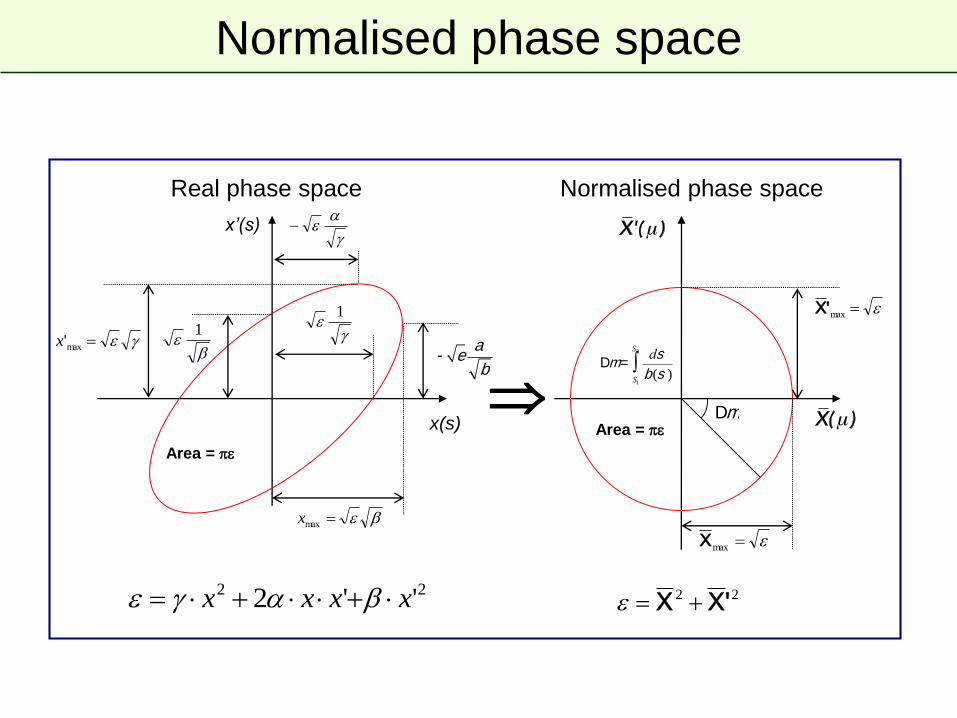
Normalised phase space
1
x(s)
xrsquo(s)
1maxx
maxx
Area = p
maxX
maxX
Area = p
22 2 xxxx 22 XX
Real phase space Normalised phase space
Dm
- ea
b Dm =ds
b(s )S1
S2
ograve
Single-turn injectionNormalised phase space at centre of idealised septum
X
X
Single-turn injection
septum
Normalised phase space at centre of idealised septum
X
X
Single-turn injection
μ2 phase advance to kicker location
X
X
Single-turn injection
Kicker deflection places beam on central orbit
X
X
Normalised phase space at centre of idealised kicker
kicker
Injection oscillations
X
X
kicker - Δ
For imperfect injection the beam oscillates around the central orbit
eg kick error Δ
Injection oscillations
X
X
After 1 turnhellip
For imperfect injection the beam oscillates around the central orbit
eg kick error Δ
Injection oscillations
X
X
After 2 turnshellip
For imperfect injection the beam oscillates around the central orbit
eg kick error Δ
Injection oscillations
X
X
After 3 turns etchellip
For imperfect injection the beam oscillates around the central orbit
eg kick error Δ
Injection oscillations
bull Betatron oscillations with respect to the Closed Orbit
Transfer line LHC (first turn)
Horizontal
Vertical
bull Angular errors from septa and kicker have different orbit pattern
bull Correct the difference between injected beam and closed orbit
or 1st and 2nd turn
Filamentation
bull Non-linear effects (eg higher-order field components) introduce
amplitude-dependent effects into particle motion
bull Over many turns a phase-space oscillation is transformed into an
emittance increase
bull So any residual transverse oscillation will lead to an emittance blow-up
through filamentation
ndash ldquoTransverse damperrdquo systems are used to damp injection oscillations -
bunch position measured by a pick-up which is linked to a kicker
ndash Chromaticity coupled with a non-zero momentum spread at injection can
also cause filmentation often termed chromatic decoherence
bull See appendix for derivation of the emittance increase
X
X
Filamentation
X
X
Filamentation
X
X
Filamentation
X
X
Filamentation
X
X
Filamentation
X
X
Filamentation
X
X
Filamentation
X
X
Filamentation
X
X
Filamentation
X
X
Filamentation
bull Residual transverse oscillations lead to an effective emittance blow-
up through filamentation
bull Due to tune spread and energy spread the oscillation will not be
seen for long on a BPM signal
Inje
ctio
n o
scill
ation
Reference closed orbit
Filamentation - Decoherence
Multi-turn injection
bull For hadrons the beam density at injection can be limited either by
space charge effects or by the injector capacity
bull If we cannot increase charge density we can sometimes fill the
horizontal phase space to increase overall injected intensity
ndash Cannot inject into same phase space area as we would kick out the
beam located there
ndash If the acceptance of the receiving machine is larger than the delivered
beam emittance we can accumulate intensity
Multi-turn injection for hadrons
Septum magnet
bull No kicker but fast programmable bumpers
bull Bump amplitude decreases and a new batch injected turn-by-turn
bull Phase-space ldquopaintingrdquo
Programmable closed orbit bump
Circulating beam
1
Turn 1
Septum
X
X
Example CERN PSB injection high intensity beams fractional tune Qh asymp 025
Beam rotates π2 per turn in phase space
On each turn inject a new batch and reduce the bump amplitude
Multi-turn injection for hadrons
1
2
Turn 2
X
X
Septum
Multi-turn injection for hadrons
Example CERN PSB injection high intensity beams fractional tune Qh asymp 025
Beam rotates π2 per turn in phase space
3
2
1
Turn 3
X
X
Septum
Multi-turn injection for hadrons
Example CERN PSB injection high intensity beams fractional tune Qh asymp 025
Beam rotates π2 per turn in phase space
4
1
2
3
Turn 4
X
X
Septum
Multi-turn injection for hadrons
Example CERN PSB injection high intensity beams fractional tune Qh asymp 025
Beam rotates π2 per turn in phase space
3
2
4
51
Turn 5
X
X
Septum
Multi-turn injection for hadrons
Example CERN PSB injection high intensity beams fractional tune Qh asymp 025
Beam rotates π2 per turn in phase space
6
5
4
3
2
1
Turn 6
X
X
Septum
Multi-turn injection for hadrons
Example CERN PSB injection high intensity beams fractional tune Qh asymp 025
Beam rotates π2 per turn in phase space
7
6
5
4
3
2
1
Turn 7
X
X
Septum
Multi-turn injection for hadrons
Example CERN PSB injection high intensity beams fractional tune Qh asymp 025
Beam rotates π2 per turn in phase space
7
6
5
4
3
21
8
Turn 8
X
X
Septum
Multi-turn injection for hadrons
Example CERN PSB injection high intensity beams fractional tune Qh asymp 025
Beam rotates π2 per turn in phase space
7
6
5
4
3
2
1
8
9
Turn 9
X
X
Septum
Multi-turn injection for hadrons
Example CERN PSB injection high intensity beams fractional tune Qh asymp 025
Beam rotates π2 per turn in phase space
7
6
5
4
3
2
1
8
9
10
Turn 10
X
X
Septum
Multi-turn injection for hadrons
Example CERN PSB injection high intensity beams fractional tune Qh asymp 025
Beam rotates π2 per turn in phase space
7
6
5
4
3
2
1
8
9
10
11
Turn 11
X
X
Septum
Multi-turn injection for hadrons
Example CERN PSB injection high intensity beams fractional tune Qh asymp 025
Beam rotates π2 per turn in phase space
7
6
5
4
3
21
8
9
10
11
Turn 12
X
X
Septum
Multi-turn injection for hadrons
Example CERN PSB injection high intensity beams fractional tune Qh asymp 025
Beam rotates π2 per turn in phase space
7
6
5
4
3
2
1
8
9
10
11
Turn 13
X
X
Septum
Multi-turn injection for hadrons
Example CERN PSB injection high intensity beams fractional tune Qh asymp 025
Beam rotates π2 per turn in phase space
7
6
5
4
3
2
1
8
9
10
11
Turn 14
X
X
Septum
Multi-turn injection for hadrons
Example CERN PSB injection high intensity beams fractional tune Qh asymp 025
Beam rotates π2 per turn in phase space
7
6
5
4
3
2
1
8
9
10
11
Turn 15
In reality filamentation (often space-charge driven) occurs to produce a quasi-
uniform beam
X
X
Phase space has been ldquopaintedrdquo
Multi-turn injection for hadrons
Charge exchange H- injection
bull Multi-turn injection is essential to accumulate high intensity
bull Disadvantages inherent in using an injection septum
ndash Width of several mm reduces aperture
ndash Beam losses from circulating beam hitting septum
bull typically 30 ndash 40 for the CERN PSB injection at 50 MeV
ndash Limits number of injected turns to 10 ndash 20
bull Charge-exchange injection provides elegant alternative
ndash Possible to ldquocheatrdquo Liouvillersquos theorem which says that emittance is
conservedhellip
ndash Convert H- to p+ using a thin stripping foil allowing injection into the
same phase space area
Charge exchange H- injection
Injection chicane dipoles
Circulating p+
Stripping foil
H0
Circulating p+
Start of injection process
Charge exchange H- injection
Circulating p+
Stripping foil
End of injection process with painting
H0
Injection chicane dipoles
Displace orbit
Circulating p+
Accumulation process on foil
V Forte Performance of the CERN PSB at 160 MeV with H- charge exchange injection PhD thesis ndash CERN and Universiteacute Blaise Pascal
bull Linac4 connection to the PS booster at 160 MeV
ndash H- stripped to p+ with an estimated efficiency asymp98 with C foil 200 μgcm-2
Charge exchange H- injection
bull Paint uniform transverse phase space density by modifying closed
orbit bump and steering injected beam
bull Foil thickness calculated to double-strip most ions (asymp99)
ndash 50 MeV ndash 50 μgcm-2
ndash 800 MeV ndash 200 μgcm-2 (asymp 1 μm of C)
bull Carbon foils generally used ndash very fragile
bull Injection chicane reduced or switched off after injection to avoid
excessive foil heating and beam blow-up
bull Longitudinal phase space can also be painted turn-by-turn
ndash Variation of the injected beam energy turn-by-turn (linac voltage scaled)
ndash Chopper system in linac to match length of injected batch to bucket
H- injection - painting
Timexrsquo vs x yrsquo vs y y vs x
Note injection into
same phase
space area as
circulating beam
asymp100 turns
Lepton injection
bull Single-turn injection can be used as for hadrons however lepton
motion is strongly damped (different with respect to proton or ion
injection)
ndash Synchrotron radiation
bull see Electron Beam Dynamics lectures by L Rivkin
bull Can use transverse or longitudinal damping
ndash Transverse - Betatron accumulation
ndash Longitudinal - Synchrotron accumulation (2 x faster than transverse)
Betatron lepton injection
bull Beam is injected with an angle with respect to the closed orbit
bull Injected beam performs damped betatron oscillations about the closed orbit
Septum magnet
Closed orbit bumpers or kickers
Circulating
beam
Betatron lepton injection
Injected bunch performs damped betatron oscillations
In LEP at 20 GeV the damping time was about 6rsquo000 turns (06 seconds)
X
X
Synchrotron lepton injection
Septum magnet
bull Beam injected parallel to circulating beam onto dispersion orbit of a
particle having the same momentum offset Δpp
bull Injected beam makes damped synchrotron oscillations at Qs but does
not perform betatron oscillations
Closed orbit bumpers or kickersxs = Dx Δpp0
xsp = p0
p = p0 + Δp
Inject an off-momentum beam
at a location with dispersion
Synchrotron lepton injection
F
E
Double batch injection possiblehellip
Longitudinal damping time in LEP was ~3rsquo000 turns (2x faster than transverse)
Injection 1 (turn N)
Injection 2 (turn N + Qs2)
Stored beam
RF bucket
Synchrotron lepton injection in LEP
Synchrotron injection in LEP gave improved background for LEP experiments
due to small orbit offsets in zero dispersion straight sections
Injection - summary
bull Several different techniques using kickers septa and bumpers
ndash Single-turn injection for hadrons
bull Boxcar stacking transfer between machines in accelerator chain
bull Angle position errors injection oscillations
bull Uncorrected errors filamentation emittance increase
ndash Multi-turn injection for hadrons
bull Phase space painting to increase intensity
bull H- injection allows injection into same phase space area
ndash Lepton injection take advantage of damping
bull Less concerned about injection precision and matching
Extraction
bull Different extraction techniques exist depending on requirements
ndash Fast extraction le1 turn
ndash Non-resonant (fast) multi-turn extraction few turns
ndash Resonant low-loss (fast) multi-turn extraction few turns
ndash Resonant multi-turn extraction many thousands of turns
bull Usually higher energy than injection stronger elements (intBdl)
ndash At high energies many kicker and septum modules may be required
ndash To reduce kicker and septum strength beam can be moved near to
septum by closed orbit bump
ndash Beam size scales with 1 120574 =gt smaller than injection
Fast single turn extraction
Septum magnet
Kicker magnet
bull Bumpers move circulating beam close to septum to reduce kicker strength
bull Kicker deflects the entire beam into the septum in a single turn
bull Most efficient (lowest deflection angles required) for π2 phase advance
between kicker and septum
Closed orbit bumpers
Entire beam kicked into septum gap and extracted over a single turn
F-quad D-quad
Circulating
beam
t
kicker field
intensity
Fast single turn extraction
bull For transfer of beams between accelerators in an injector chain
bull For secondary particle production
ndash eg neutrinos radioactive beams
bull Losses from transverse scraping or from particles in extraction gap
ndash Fast extraction from SPS to CNGS
1E+08
1E+09
1E+10
1E+11
0 1 2 3 4 5 6 7 8 9 10 11 12 13 14 15time us
p+
00
02
04
06
08
10
12 kk
o
Intensity [10^9 p25ns]
Kicker strength
Particles in SPS extraction kicker rise- and fall-time gaps
Multi-turn extraction
bull Some filling schemes require a beam to be injected in several turns to
a larger machinehellip
bull And very commonly Fixed Target physics experiments and medical
accelerators often need a quasi-continuous flux of particleshellip
bull Multi-turn extractionhellip
ndash Fast Non-resonant and resonant multi-turn ejection (few turns) for filling
bull eg PS to SPS at CERN for high intensity proton beams (gt25 1013 protons)
ndash Slow Resonant extraction (ms to hours) for experiments
Extracted beamMagnetic
septum
bull Fast bumper deflects the whole beam onto the septum
bull Beam extracted in a few turns with the machine tune rotating the beam
bull Intrinsically a high-loss process thin septum essential
bull Often combine thin electrostatic septa with magnetic septa
Non-resonant multi-turn extraction
Fast closed orbit bumpers
Beam bumped to septum part of beam lsquoshavedrsquo off each turn
Electrostatic
septum
Non-resonant multi-turn extraction
bull Example system CERN PS to SPS Fixed-Target lsquocontinuous transferrsquo
ndash Accelerate beam in PS to 14 GeVc
ndash Empty PS machine (21 μs long) in 5 turns into SPS
ndash Do it again
ndash Fill SPS machine (11 x CPS 23 μs long)
ndash Quasi-continuous beam in SPS (2 x 1 μs gaps)
ndash Total intensity per PS extraction asymp 3 1013 p+
ndash Total intensity in SPS asymp 5 1013 p+
Extracted beam
beam
To the SPS
The PS
Non-resonant multi-turn extraction
X
X
CERN PS to SPS 5-turn continuous transfer ndash 1st turn
Qh = 025
1 2 3 4 5
Bump vs turn
1
2
3
4
5
septum
Non-resonant multi-turn extraction
X
X
CERN PS to SPS 5-turn continuous transfer ndash 2nd turn
Qh = 025
1 2 3 4 5
Bump vs turn
1
2
3
4 5
septum
Non-resonant multi-turn extraction
X
X
CERN PS to SPS 5-turn continuous transfer ndash 3rd turn
Qh = 025
1 2 3 4 5
Bump vs turn
septum
1
2
3
4
5
Non-resonant multi-turn extraction
X
X
CERN PS to SPS 5-turn continuous transfer ndash 4th turn
Qh = 025
1 2 3 4 5
Bump vs turn
septum
1
2
3
45
Non-resonant multi-turn extraction
X
X
CERN PS to SPS 5-turn continuous transfer ndash 5th turn
Qh = 025
5
1 2 3 4 5
Bump vs turn
Non-resonant multi-turn extraction
bull CERN PS to SPS 5-turn continuous transfer
ndash Losses impose thin septumhellip
hellip an electrostatic septum is needed in addition to the magnetic septum
ndash Still about 15 of beam lost in PS-SPS CT
ndash Difficult to get equal intensities per turn
ndash Different trajectories for each turn
ndash Different emittances for each turn
X
X
1
X
X
2
X
X
3
X
X
4
X
X
5
I
1 2 3 4 5
Resonant multi-turn (fast) extraction
bull Adiabatic capture of beam in stable ldquoislandsrdquo
- Use non-linear fields (sextupoles and octupoles) to create islands of
stability in phase space
- A slow (adiabatic) tune variation to cross a resonance and to drive
particles into the islands (capture) with the help of transverse excitation
(using damper)
- Variation of field strengths to separate the islands in phase space
bull Several big advantages
ndash Losses reduced significantly (no particles at the septum in transverse
plane)
ndash Phase space matching improved with respect to existing non-resonant
multi-turn extraction - lsquobeamletsrsquo have similar emittance and optical
parameters
Resonant multi-turn (fast) extraction
a Unperturbed beam
b Increasing non-linear
fields
a Beam captured in
stable islands
b Islands separated and
beam bumped across
septum ndash extracted in
5 turns
(see Non-Linear Beam Dynamics lectures
by Y Papaphilippou)
Courtesy M Giovannozzi MTE Design Report CERN-2006-011 2006
Resonant multi-turn (fast) extraction
Septum wire
1 2 3 4 5
Bump vs turn
Qh = 025
a Unperturbed beam
b Increasing non-linear
fields
a Beam captured in
stable islands
b Islands separated and
beam bumped across
septum ndash extracted in
5 turns
Courtesy M Giovannozzi MTE Design Report CERN-2006-011 2006
Extracted beam
bull Slow bumpers move the beam near the septum
bull Tune adjusted close to nth order betatron resonance
bull Multipole magnets excited to define stable area in phase space size
depends on ΔQ = Q - Qr
Resonant multi-turn (slow) extraction
Closed orbit bumpers
Non-linear fields excite resonances that drive the beam slowly across the septum
Magnetic
septum
Electrostatic
septum
Resonant multi-turn (slow) extraction
bull 3rd order resonances ndash see lectures by Y Papaphilippou
ndash Sextupole fields distort the circular normalised phase space particle trajectories
ndash Stable area defined delimited by unstable Fixed Points
ndash Sextupole magnets arranged to produce suitable phase space orientation of the stable triangle at thin electrostatic septum
ndash Stable area can be reduced byhellip
bull Increasing the sextupole strength orhellip
bull Fixing the sextupole strength and scanning the machine tune Qh (and therefore the resonance) through the tune spread of the beam
bull Large tune spread created with RF gymnastics (large momentum spread) and large chromaticity
2
21 1
kQR fp
Rfp
Third-order resonant extraction
bull Particles distributed on emittance contours
bull ΔQ large ndash no phase space distortion
X
X
Septum wire
Third-order resonant extraction
bull Sextupole magnets produce a triangular stable area in phase space
bull ΔQ decreasing ndash phase space distortion for largest amplitudes
X
X
Septum wire
Third-order resonant extraction
X
X
Septum wire
bull Sextupole magnets produce a triangular stable area in phase space
bull ΔQ decreasing ndash phase space distortion for largest amplitudes
Third-order resonant extraction
X
X
Septum wire
bull Sextupole magnets produce a triangular stable area in phase space
bull ΔQ decreasing ndash phase space distortion for largest amplitudes
Third-order resonant extraction
X
X
Septum wire
bull Sextupole magnets produce a triangular stable area in phase space
bull ΔQ decreasing ndash phase space distortion for largest amplitudes
Third-order resonant extraction
bull Largest amplitude particle trajectories are significantly distorted
bull Locations of fixed points noticeable at extremities of phase space triangle
X
X
Septum wire
Third-order resonant extraction
X
X
Septum wire
bull ΔQ small enough that largest amplitude particle trajectories are unstable
bull Unstable particles follow separatrix branches as they increase in amplitude
Third-order resonant extraction
X
X
Septum wire
bull Stable area shrinks as ΔQ becomes smaller
Third-order resonant extraction
X
X
Septum wire
bull Separatrix position in phase space shifts as the stable area shrinks
Third-order resonant extraction
bull As the stable area shrinks the circulating beam intensity drops since
particles are being continuously extracted
X
X
Septum wire
Third-order resonant extraction
X
X
Septum wire
bull As the stable area shrinks the circulating beam intensity drops since
particles are being continuously extracted
Third-order resonant extraction
X
X
Septum wire
bull As the stable area shrinks the circulating beam intensity drops since
particles are being continuously extracted
Third-order resonant extraction
X
X
Septum wire
bull As the stable area shrinks the circulating beam intensity drops since
particles are being continuously extracted
Third-order resonant extraction
X
X
Septum wire
bull As ΔQ approaches zero the particles with very small amplitude are
extracted
Slow extracted spill quality
Reducing Q with main machine quadrupoles can be augmented with a
lsquoservorsquo quadrupole which can modulate Q in a servo loop acting on
a measurement of the spill intensity
50 Hz
10 Hz
An example of a spill at SPS to the North Area with large n x 50 Hz
components and another noise source at 10 Hz
bull The slow-extraction is a resonant process and it amplifies the smallest
imperfections in the machine- eg spill intensity variations can be explained by ripples in the current of the
quads (mains n x 50 Hz) at the level of a few ppm
- Injection of n x 50 Hz signals in counter-phase on dedicated quads can be
used to compensate
Extraction - summary
bull Several different techniques
ndash Single-turn fast extraction
bull for transfer between machines in accelerator chain beam abort etc
ndash Non-resonant (fast) multi-turn extraction
bull slice beam into equal parts for transfer between machine over a few turns
ndash Resonant low-loss (fast) multi-turn extraction
bull create stable islands in phase space slice off over a few turns
ndash Resonant (slow) multi-turn extraction
bull create stable area in phase space slowly drive particles into resonance long spill over many thousand turns
1 Extract a beam out of one machine initial beam parameters
2 Transport this beam towards the following machine (or experiment)
3 Inject this beam into a following machine with a predefined optics
Transfer line optics has to produce required beam parameters for matching
Linking Machines
Extraction
Transfer
Injection
s
(αx βx Dx Drsquoxαy βy Dy Drsquoy)1 M12
(αx βx Dx Drsquoxαy βy Dy Drsquoy)2
Linking Machines
bull Beams have to be transported from extraction of one machine to
injection of the next machine
- Trajectory must be matched in all 6 geometric degrees of freedom
(xyzθΦψ)
bull Linking the optics is a complicated process
- Parameters at start of line have to be propagated to matched parameters
at the end of the line (injection to another machine fixed target etc )
- Need to ldquomatchrdquo 8 variables (αx βx Dx Drsquox and αy βy Dy Drsquoy)
- Done with number of independently power (ldquomatchingrdquo) quadrupoles
- Maximum β and D values are imposed by magnetic apertures
- Other constraints exist
- Phase conditions for collimators
- Insertions for special equipment like stripping foils
- hellip
bull Matching with computer codes and relying on mixture of theory experience
intuition trial and error
Optics Matching example
0
50
100
150
200
250
300
0 250 500 750 1000 1250 1500 1750 2000 2250 2500 2750 3000 3250 3500 3750 4000
S [m]
[
m]
BETXBETY
SPS LHCRegular lattice (FODO)
(elements all powered in series
with same strengths)
Final matching
section
SPS to LHC Transfer Line (3 km)Extraction
point Injection
point
Initial matching
section
Independently powered (tuneable) quadrupoles
Independently powered (tuneable) quadrupoles and (in this case) passive
protection devices
Need to match 8 variables (TWISS parameters) for propagation from start to end of a transfer
Optical Mismatch at Injection
bull Filamentation fills larger ellipse with same shape as matched ellipse
x
xrsquo
Turn 0
Turn N
Time
bull Dispersion mismatch at injection will also cause emittance blow-up
Further reading and references
bull Lots of resources presented at the recent Specialised CAS School
bull Beam Injection Extraction and Transfer 10-19 March 2017 Erice Italy
bull httpscaswebcernchschoolserice-2017
Terminating
Resistor
Transmission
Line
Z
Kicker
Magnet
Z
Z
Main
Switch
PFN or
PFL
Z
RCPS
Dump
Switch
Dump
ResistorZ
Single-way Delay τp
Simplified kicker system schematic
Terminating
Resistor
Transmission
Line
Z
Kicker
Magnet
Z
Z
Main
Switch
PFN or
PFL
Z
RCPS
Dump
Switch
Dump
ResistorZ
Single-way Delay τp
bull Main sub-systems (ldquocomponentsrdquo) of kicker system
ndash RCPS = Resonant Charging Power Supply
ndash PFL = Pulse Forming Line (coaxial cable) or PFN = Pulse Forming
Network (lumped elements)
ndash Fast high power switch(es)
ndash Transmission line(s) coaxial cable(s)
ndash Kicker Magnet
ndash Terminators (resistive)
Matched impedance example
Terminating
Resistor
Transmission
Line
Z
Kicker
Magnet
Z
Z
Main
Switch
PFN or
PFL
Z
RCPS
Dump
Switch
Dump
ResistorZ
Single-way Delay τp
Simplified kicker system schematic
Terminating
Resistor
Transmission
Line
Z
Kicker
Magnet
Z
Z
Main
Switch
PFN or
PFL
Z
RCPS
Dump
Switch
Dump
ResistorZ
Single-way Delay τp
bull PFLPFN charged to voltage V0 by the RCPS
bull Main switch is closedhellip
hellipvoltage pulse of V02 flows through kicker
bull Once the pulse reaches the (matched) terminating resistor full-field has
been established in the kicker magnet
bull Pulse length controlled between t = 0 and 2p with dump switch
Matched impedance example
PFLPFN
Pulse Forming Line (PFL)
bull Low-loss coaxial cable
bull Fast and ripple-free pulses
bull Attenuation (droop ~1) becomes
problematic for pulses gt 3 μs
bull Above 50 kV SF6 pressurized PE
tape cables are used
bull Bulky 3 μs pulse ~ 300 m of cable
Pulse Forming Network (PFN)
bull Artificial coaxial cable made of lumped
elements
bull For low droop and long pulses gt 3 μs
bull Each cell individually adjustable
adjustment of pulse flat-top difficult
and time consuming
Reels of PFL used at the PS complex (as old as the photograph) SPS extraction kicker (MKE) PFN (17 cells)
Power semiconductor switches
bull Suitable for scenarios where erratic
turn-on is not allowed
bull For example LHC beam dump
kickers held at nominal voltage
throughout operation (gt10h) ready to
fire and safely abort at any moment
bull Hold off up to 30 kV and switch up to
18 kA
bull Slower switching gt 1 μs (~18kAμs)
bull Low maintenance
Switches
~ 3
40 m
m
Thyratrons
bull Deuterium gas thyratrons are commonly used
bull Hold off 80 kV and switch up to 6 kA
bull Fast switching ~ 30 ns (~150 kAμs)
bull Erratic turn-on use with RCPS to reduce hold-off time
ThyratronStack of high-power semiconductor
switches (GTOs)
Terminating
Resistor
Transmission
Line
Z
Kicker
Magnet
Z
Z
Main
Switch
PFN or
PFL
Z
RCPS
Dump
Switch
Dump
ResistorZ
Single-way Delay τp
Simplified kicker system schematic
Terminating
Resistor
Transmission
Line
Z
Kicker
Magnet
Z
Z
Main
Switch
PFN or
PFL
Z
RCPS
Dump
Switch
Dump
ResistorZ
Single-way Delay τp
V
distancet pvp
bull Pulse forming network or line (PFLPFN) charged to voltage V0 by the
resonant charging power supply (RCPS)
ndash RCPS is de-coupled from the system through a diode stack
t = 0
V0
ttime
int
kicker
field
t fill
Terminating
Resistor
Transmission
Line
Z
Kicker
Magnet
Z
Z
Main
Switch
PFN or
PFL
Z
RCPS
Dump
Switch
Dump
ResistorZ
Single-way Delay τp
Simplified kicker system schematic
Terminating
Resistor
Transmission
Line
Z
Kicker
Magnet
Z
Z
Main
Switch
PFN or
PFL
Z
RCPS
Dump
Switch
Dump
ResistorZ
Single-way Delay τp
t = 2t p +t fill
distance
V
t pvp
ttime
V0
bull A kicker pulse of approximately 2p is imparted on the beam and all
energy has been emptied into the terminating resistor
2t p
t fill t p t fill
I =V0
2Z
t fill
int
kicker
field
Terminating
Resistor
Transmission
Line
Z
Kicker
Magnet
Z
Z
Main
Switch
PFN or
PFL
Z
RCPS
Dump
Switch
Dump
ResistorZ
Single-way Delay τp
Simplified kicker system schematic
Terminating
Resistor
Transmission
Line
Z
Kicker
Magnet
Z
Z
Main
Switch
PFN or
PFL
Z
RCPS
Dump
Switch
Dump
ResistorZ
Single-way Delay τp
t raquo 2t p
distance
V
t pvp
ttime
V0
bull Kicker pulse length can be changed by adjusting the relative timing of
dump and main switches
ndash eg if the dump and main switches are fired simultaneously the pulse
length will be halved and energy shared on dump and terminating resistors
2t p
t fill t p
I =V0
2Z
t fill
t fill
int
kicker
field
Short circuit mode
bull Short-circuiting the termination offers twice the kick (for a given kicker magnet)
- Fill time of kicker magnet is doubled
- Diode as dump switch provides solution for fixed pulse length
Terminating
Resistor
Transmission
Line
Z
Kicker
Magnet
Z
Z
Main
Switch
PFN or
PFL
Z
RCPS
Dump
Switch
Dump
ResistorZ
Single-way Delay τpTerminating
Resistor
Transmission
Line
Z
Kicker
Magnet
Z
Z
Main
Switch
PFN or
PFL
Z
RCPS
Dump
Switch
Dump
ResistorZ
Single-way Delay τp
distance
Vt pvp
V0
Dump Diode
Short Circuit
-V0
2
ttime
t raquo 2(t p +t fill )
Boundary condition at
short-circuit
V = 0 doubling I
Diode conducts as voltage
flips sign and match dump
resistor absorbs energy
I =V0
Z
2(t p +t fill )
t fill
int
kicker
field
I- =V0
2Z
Kicker magnets ndash design options
bull Type ldquolumped inductancerdquo or ldquodistributed inductancerdquo (transmission line)
bull Other considerations
ndash Machine vacuum kicker in-vacuum or external
ndash Aperture geometry of ferrite core
ndash Termination matched impedance or short-circuit
VZ Lmag
From generator
(eg PFN)V
Z =Lcell
Ccell
bull simple magnet design
bull magnet must be nearby the
generator to minimise inductance
bull exponential field rise-time
bull slow rise-times ~ 1 μs
bull complicated magnet design
bull impedance matching important
bull field rise-time depends on propagation
time of pulse through magnet
bull fast rise-times ltlt 1 μs
Ccell
2
Ccell
2
Ccell
2
Ccell
2
Ccell
2
Ccell
2
Lcell Lcell Lcell
Cell 1hellip Cell n - 1 hellip Cell n
t = n Lcell timesCcell = nLcell
Z=Lmag
Z
I =V
Z(1- e-t t ) t =
Lmag
Z
Lmag = nLcellFrom generator
(eg PFN)
Magnets ndash transmission line
bull Todayrsquos fast (rise-times of lt few hundred ns) kicker magnets are generally
ferrite loaded transmission lines
ndash Ferrite C-cores are sandwiched between HV plates
ndash Grounded plates are interleaved to form a capacitor to ground
B
Ground plate
HV conductor
Return
conductor
Ferrite
HV
End Viewand so onhellip
beam
Side Viewcell
Magnets ndash transmission line
bull Todayrsquos fast (rise-times of lt few hundred ns) kicker magnets are generally
ferrite loaded transmission lines
ndash Kicker magnets consists of many relatively short cells to approximate a
broadband coaxial cable
LcLc
Cc2Cc2Cc2
Lc
Cc2Cc2
Lc
Cc2Cc2
0
Cc2
cell
1 2 (n-1) n
A real kickerhellip
Prototype for AGS
injection kicker upgrade
beam
and so onhellip
Side Viewcell
Electrostatic septum
bull Thin septum ~ 01 mm needed for high extraction efficiency
ndash Foils typically used
ndash Stretched wire arrays provide thinner septa and lower effective density
bull Challenges include conditioning and preparation of HV surfaces vacuum
in range of 10-9 ndash 10-12 mbar and in-vacuum precision position alignment
E
(up to 10 MVm
in UHV)
x
yz
d (typically 10 to 35 mm)
V (up to 300 kV)
circulating beam
extracted
beam
septum foil
(Mo or Z-Re)
electrode
(Al Ti SS)
support
Grounded support
Electrode (HV)Foil
Foil TensionersBake-out lamps for UHV
Electrostatic septum
bull At SPS we slow-extract 400 GeV protons using approximately 15 m of septum split into 5 separate vacuum tanks each over 3 m long
- Alignment of the 60 - 100 μm wire array over 15 m is challenging
DC direct drive magnetic septum
magnet yoke (laminated steel)septum
x
yz
Cooling
Electrical connectionsCirculating beam
vacuum
chamber
extracted
beam
0
B
x
x
septum
(typically 6 to 20 mm)
g
(typically
25 - 60 mm)
bull Continuously powered rarely under vacuum
bull Multi-turn coil to reduce current needed but cooling still an issue
ndash Cooling water circuits flow rate typically at 12 ndash 60 lmin
ndash Current can range from 05 to 4 kA and power consumption up to 100 kW
rear
conductor
B
septum
(typically 3 to 20 mm)
circulating
beamrear
conductor
septum
conductor
extracted
beam0
B
x
x
Direct drive pulsed magnetic septum
x
yz
Beam ldquomonitorrdquo
Beam screenBake-out lamps for UHV
Septumbull In vacuum to minimise distance between circulating and extracted beam
bull Single-turn coil to minimise inductance bake-out up to 200 degC (~10-9 mbar)
bull Pulsed by capacitor discharge (third harmonic flattens the pulse)
ndash Current in range 7 ndash 40 kA with a few ms oscillation period
ndash Cooling water circuits flow rate from 1 ndash 80 lmin
g
(typically
18 - 60 mm)
magnet yoke (laminated steel)
B
Appendix
Injection errors
kicker
bpm1 bpm2
phase m ~p2 ~p2~p2
septum
Angle errors
sk
Measured
Displacements
d12
s k
d1
d2
Dqk bk
At kicker location
Injection errors
kicker
bpm1 bpm2
phase m ~p2 ~p2~p2
septum
Angle errors
sk
Measured
Displacements
d12
d1 = s (s1) sin (m1 ndash ms) + k (k1) sin (m1 ndash mk)
asymp k (k1)
s k
d1
d2
Dqk bk
x
b1
raquo Dqk bk
At BPM1 location
d2 = s (s2) sin (m2 ndash ms) + k (k2) sin (m2 ndash mk)
asymp -s (s2)
Blow-up from steering error
X
X
Misinjected
beam
Matched
particles
L
A0
bull The new particle coordinates in normalised phase space are
Xerror = X0 +Lcosq
X error = X 0+Lsinq
bull For a general particle distribution
where Ai denotes amplitude in
normalised phase of particle i
bull The emittance of the distribution is
L = Da ematched
bull So we plug in the new coordinates
bull Taking the average over distribution
bull Giving the diluted emittance as
Blow-up from steering error
0
X
X
Effect of steering error on a given particle
Matched
particles
A
L
= (X0 +Lcosq)2 + (X 0+Lsinq)2
= X0
2 +X 02+2L(X0 cosq +X 0sinq)+L2
cos2q +sin2q =1
0
= 2ematched +L2
ediluted =ematched +L2
2
L = Da ematched
=ematched 1+Da2
2
eacute
eumlecirc
ugrave
ucircuacute
Blow-up from steering error
bull Consider a collection of particles with max amplitudes A
bull The beam can be injected with an error in angle and position
bull For an injection error Δa in units of σ = (βε) the mis-injected beam is
offset in normalised phase space by an amplitude L = Δaε
X
X
Misinjected
beam
Matched
particles
L
A
Blow-up from steering error
bull Consider a collection of particles with max amplitudes A
bull The beam can be injected with an error in angle and position
bull For an injection error Δa in units of σ = (βε) the mis-injected beam is
offset in normalised phase space by an amplitude L = Δaε
X
X
Misinjected
beam
Matched
particles
L
A
Blow-up from steering error
bull Consider a collection of particles with max amplitudes A
bull The beam can be injected with an error in angle and position
bull For an injection error Δa in units of σ = (βε) the mis-injected beam is
offset in normalised phase space by an amplitude L = Δaε
X
X
Misinjected
beam
Matched
particles
L
A
Blow-up from steering error
bull Consider a collection of particles with max amplitudes A
bull The beam can be injected with an error in angle and position
bull For an injection error Δa in units of σ = (βε) the mis-injected beam is
offset in normalised phase space by an amplitude L = Δaε
X
XMatched
particles
A
L
bull Any given point on the matched ellipse
is randomised over all phases after
filamentation due to the steering error
Effect of steering error on a given particle
Blow-up from steering error
bull Consider a collection of particles with max amplitudes A
bull The beam can be injected with an error in angle and position
bull For an injection error Δa in units of σ = (βε) the mis-injected beam is
offset in normalised phase space by an amplitude L = Δaε
X
XMatched
particles
A
L
bull Any given point on the matched ellipse
is randomised over all phases after
filamentation due to the steering error
bull For a general particle distribution
where Ai denotes amplitude in
normalised phase of particle i
Effect of steering error on a given particle
Blow-up from steering error
bull Consider a collection of particles with max amplitudes A
bull The beam can be injected with an error in angle and position
bull For an injection error Δa in units of σ = (βε) the mis-injected beam is
offset in normalised phase space by an amplitude L = Δaε
X
X
Effect of steering error on a given particle
Matched
particles
A
L
bull Any given point on the matched ellipse
is randomised over all phases after
filamentation due to the steering error
bull For a general particle distribution
where Ai denotes amplitude in
normalised phase of particle i
bull After filamentation
ediluted =ematched +L2
2
See appendix for derivation
bull A numerical examplehellip
bull Consider an offset Δa = 05σ for injected beam
bull For nominal LHC beam
hellipallowed growth through LHC cycle ~10
Blow-up from steering error
Misinjected beam
Matched
Beam
05
X
Xediluted =ematched +L2
2
L = Da ematched
=ematched 1+Da2
2
eacute
eumlecirc
ugrave
ucircuacute
=ematched 1125[ ]
Particle at turn 0
bull On resonance sextupole kicks add-up driving particles over septum
Third-order resonant extraction
Particle at turn 1
bull On resonance sextupole kicks add-up driving particles over septum
Third-order resonant extraction
Particle at turn 2
bull On resonance sextupole kicks add-up driving particles over septum
Third-order resonant extraction
Particle at turn 3
bull On resonance sextupole kicks add-up driving particles over septum
Third-order resonant extraction
bull On resonance sextupole kicks add-up driving particles over septum
ndash Distance travelled in these final three turns is termed the ldquospiral steprdquo ΔXES
ndash Extraction bump trimmed in the machine to adjust the spiral step
Extracted beam
Third-order resonant extraction
DXES micro k2
XES2
cosqDXES
XES
bull On resonance sextupole kicks add-up driving particles over septum
ndash Distance travelled in these final three turns is termed the ldquospiral steprdquo ΔXES
ndash Extraction bump trimmed in the machine to adjust the spiral step
bull RF gymnastics before extraction
Extracted beam
Third-order resonant extraction
DXES micro k2
XES2
cosqDXES
XES
Dp
pmicro-DQ
momentum spread tune
-30dBm
dBm-130
A Ch1 Spectrum 0 dBmRange
10 kHzSpan Center 110355665 GHz3820312 mSecTimeLen RBW 100 Hz
4375 Sec
7969 Sec
3578 Sec
Spill = 48 stim
e
Schottky measurement during spill courtesy of T Bohl
Δϕ = π
Δϕ = -π
small Δp
rotation large Δp
RF
off
RF gymn
216 217 218electrostatic septum (ES)QFA QDA
magnetic
septum (MST) magnetic septum (MSE)QFA
TPST
maskextraction
bumper
To TT20
and NA
ES
Slow extraction channel SPS
Second-order resonant extraction
bull An extraction can also be made over a few hundred turns
bull 2nd and 4th order resonances
ndash Octupole fields distort the regular phase space particle trajectories
ndash Stable area defined delimited by two unstable Fixed Points
ndash Beam tune brought across a 2nd order resonance (Q rarr 05)
ndash Particle amplitudes quickly grow and beam is extracted in a few
hundred turns
Resonant extraction separatrices
bull Amplitude growth for 2nd order resonance much faster than 3rd ndash shorter
spills (asympmilliseconds vs seconds)
bull Used where intense pulses are required on target ndash eg neutrino production
X
X 3rd order resonant extraction 2nd order resonant extraction
Terminating
Resistor
Transmission
Line
Z
Kicker
Magnet
Z
Z
Main
Switch
PFN or
PFL
Z
RCPS
Dump
Switch
Dump
ResistorZ
Single-way Delay τp
Simplified kicker system schematic
Terminating
Resistor
Transmission
Line
Z
Kicker
Magnet
Z
Z
Main
Switch
PFN or
PFL
Z
RCPS
Dump
Switch
Dump
ResistorZ
Single-way Delay τp
V
distancet pvp
bull Pulse forming network or line (PFLPFN) charged to voltage V0 by the
resonant charging power supply (RCPS)
ndash RCPS is de-coupled from the system through a diode stack
t = 0
V0
ttime
int
kicker
field
t fill
Terminating
Resistor
Transmission
Line
Z
Kicker
Magnet
Z
Z
Main
Switch
PFN or
PFL
Z
RCPS
Dump
Switch
Dump
ResistorZ
Single-way Delay τp
Simplified kicker system schematic
Terminating
Resistor
Transmission
Line
Z
Kicker
Magnet
Z
Z
Main
Switch
PFN or
PFL
Z
RCPS
Dump
Switch
Dump
ResistorZ
Single-way Delay τp
t raquo 0
distance
bull Pulse forming network or line (PFLPFN) charged to voltage V0 by the
resonant charging power supply (RCPS)
ndash RCPS is de-coupled from the system through a diode stack
bull At t = 0 main switch is closed and current starts to flow into the kicker
I =V0
2Z
V
t pvp
V0
ttime
int
kicker
field
t fill
Terminating
Resistor
Transmission
Line
Z
Kicker
Magnet
Z
Z
Main
Switch
PFN or
PFL
Z
RCPS
Dump
Switch
Dump
ResistorZ
Single-way Delay τp
Simplified kicker system schematic
Terminating
Resistor
Transmission
Line
Z
Kicker
Magnet
Z
Z
Main
Switch
PFN or
PFL
Z
RCPS
Dump
Switch
Dump
ResistorZ
Single-way Delay τp
t raquo t fill
distance
bull At t = fill the voltage pulse of magnitude V02 has propagated through
the kicker and nominal field achieved with a current V02Z
ndash typically p gtgt fill (schematic for illustration purposes)
V0
2
V
t pvp
V0
I =V0
2Z
ttimet fill
t fill
int
kicker
field
Terminating
Resistor
Transmission
Line
Z
Kicker
Magnet
Z
Z
Main
Switch
PFN or
PFL
Z
RCPS
Dump
Switch
Dump
ResistorZ
Single-way Delay τp
Simplified kicker system schematic
Terminating
Resistor
Transmission
Line
Z
Kicker
Magnet
Z
Z
Main
Switch
PFN or
PFL
Z
RCPS
Dump
Switch
Dump
ResistorZ
Single-way Delay τp
t raquo t p
distance
bull PFN continues to discharge energy into kicker magnet and matched
terminating resistor
V0
2
V
t pvp
V0
I =V0
2Z
ttimet fill t p
I =V0
2Z
t fill
int
kicker
field
Terminating
Resistor
Transmission
Line
Z
Kicker
Magnet
Z
Z
Main
Switch
PFN or
PFL
Z
RCPS
Dump
Switch
Dump
ResistorZ
Single-way Delay τp
Simplified kicker system schematic
Terminating
Resistor
Transmission
Line
Z
Kicker
Magnet
Z
Z
Main
Switch
PFN or
PFL
Z
RCPS
Dump
Switch
Dump
ResistorZ
Single-way Delay τp
t raquo t p
distance
bull PFN continues to discharge energy into kicker magnet and matched
terminating resistor
bull At t asymp p the negative pulse reflects off the open end of the circuit
(dump switch) and back towards the kicker
V0
2
V
t pvp
V0
I =V0
2Z
ttimet fill t p
I =V0
2Z
t fill
int
kicker
field
Terminating
Resistor
Transmission
Line
Z
Kicker
Magnet
Z
Z
Main
Switch
PFN or
PFL
Z
RCPS
Dump
Switch
Dump
ResistorZ
Single-way Delay τp
Simplified kicker system schematic
Terminating
Resistor
Transmission
Line
Z
Kicker
Magnet
Z
Z
Main
Switch
PFN or
PFL
Z
RCPS
Dump
Switch
Dump
ResistorZ
Single-way Delay τp
t raquo t p
distance
V0
2
V
t pvp
I =V0
2Z
V0
bull PFN continues to discharge energy into matched terminating resistor
bull At t asymp p the negative pulse reflects off the open end of the circuit and
back towards the kicker
ttimet fill t p
I =V0
2Z
t fill
int
kicker
field
Terminating
Resistor
Transmission
Line
Z
Kicker
Magnet
Z
Z
Main
Switch
PFN or
PFL
Z
RCPS
Dump
Switch
Dump
ResistorZ
Single-way Delay τp
Simplified kicker system schematic
Terminating
Resistor
Transmission
Line
Z
Kicker
Magnet
Z
Z
Main
Switch
PFN or
PFL
Z
RCPS
Dump
Switch
Dump
ResistorZ
Single-way Delay τp
t raquo 2t p
distance
V0
2
V
t pvp
I =V0
2Z
V0
bull At t asymp 2p the pulse arrives at the kicker and field starts to decay
ttimet fill t p
I =V0
2Z
t fill
int
kicker
field
Terminating
Resistor
Transmission
Line
Z
Kicker
Magnet
Z
Z
Main
Switch
PFN or
PFL
Z
RCPS
Dump
Switch
Dump
ResistorZ
Single-way Delay τp
Simplified kicker system schematic
Terminating
Resistor
Transmission
Line
Z
Kicker
Magnet
Z
Z
Main
Switch
PFN or
PFL
Z
RCPS
Dump
Switch
Dump
ResistorZ
Single-way Delay τp
t = 2t p +t fill
distance
V
t pvp
ttime
V0
bull A kicker pulse of approximately 2p is imparted on the beam and all
energy has been emptied into the terminating resistor
2t p
t fill t p t fill
I =V0
2Z
t fill
int
kicker
field
Terminating
Resistor
Transmission
Line
Z
Kicker
Magnet
Z
Z
Main
Switch
PFN or
PFL
Z
RCPS
Dump
Switch
Dump
ResistorZ
Single-way Delay τp
Simplified kicker system schematic
Terminating
Resistor
Transmission
Line
Z
Kicker
Magnet
Z
Z
Main
Switch
PFN or
PFL
Z
RCPS
Dump
Switch
Dump
ResistorZ
Single-way Delay τp
t raquo 2t p
distance
V
t pvp
ttime
V0
bull Kicker pulse length can be changed by adjusting the relative timing of
dump and main switches
ndash eg if the dump and main switches are fired simultaneously the pulse
length will be halved and energy shared on dump and terminating resistors
2t p
t fill t p
I =V0
2Z
t fill
t fill
int
kicker
field

Single-turn injection
septum
Normalised phase space at centre of idealised septum
X
X
Single-turn injection
μ2 phase advance to kicker location
X
X
Single-turn injection
Kicker deflection places beam on central orbit
X
X
Normalised phase space at centre of idealised kicker
kicker
Injection oscillations
X
X
kicker - Δ
For imperfect injection the beam oscillates around the central orbit
eg kick error Δ
Injection oscillations
X
X
After 1 turnhellip
For imperfect injection the beam oscillates around the central orbit
eg kick error Δ
Injection oscillations
X
X
After 2 turnshellip
For imperfect injection the beam oscillates around the central orbit
eg kick error Δ
Injection oscillations
X
X
After 3 turns etchellip
For imperfect injection the beam oscillates around the central orbit
eg kick error Δ
Injection oscillations
bull Betatron oscillations with respect to the Closed Orbit
Transfer line LHC (first turn)
Horizontal
Vertical
bull Angular errors from septa and kicker have different orbit pattern
bull Correct the difference between injected beam and closed orbit
or 1st and 2nd turn
Filamentation
bull Non-linear effects (eg higher-order field components) introduce
amplitude-dependent effects into particle motion
bull Over many turns a phase-space oscillation is transformed into an
emittance increase
bull So any residual transverse oscillation will lead to an emittance blow-up
through filamentation
ndash ldquoTransverse damperrdquo systems are used to damp injection oscillations -
bunch position measured by a pick-up which is linked to a kicker
ndash Chromaticity coupled with a non-zero momentum spread at injection can
also cause filmentation often termed chromatic decoherence
bull See appendix for derivation of the emittance increase
X
X
Filamentation
X
X
Filamentation
X
X
Filamentation
X
X
Filamentation
X
X
Filamentation
X
X
Filamentation
X
X
Filamentation
X
X
Filamentation
X
X
Filamentation
X
X
Filamentation
bull Residual transverse oscillations lead to an effective emittance blow-
up through filamentation
bull Due to tune spread and energy spread the oscillation will not be
seen for long on a BPM signal
Inje
ctio
n o
scill
ation
Reference closed orbit
Filamentation - Decoherence
Multi-turn injection
bull For hadrons the beam density at injection can be limited either by
space charge effects or by the injector capacity
bull If we cannot increase charge density we can sometimes fill the
horizontal phase space to increase overall injected intensity
ndash Cannot inject into same phase space area as we would kick out the
beam located there
ndash If the acceptance of the receiving machine is larger than the delivered
beam emittance we can accumulate intensity
Multi-turn injection for hadrons
Septum magnet
bull No kicker but fast programmable bumpers
bull Bump amplitude decreases and a new batch injected turn-by-turn
bull Phase-space ldquopaintingrdquo
Programmable closed orbit bump
Circulating beam
1
Turn 1
Septum
X
X
Example CERN PSB injection high intensity beams fractional tune Qh asymp 025
Beam rotates π2 per turn in phase space
On each turn inject a new batch and reduce the bump amplitude
Multi-turn injection for hadrons
1
2
Turn 2
X
X
Septum
Multi-turn injection for hadrons
Example CERN PSB injection high intensity beams fractional tune Qh asymp 025
Beam rotates π2 per turn in phase space
3
2
1
Turn 3
X
X
Septum
Multi-turn injection for hadrons
Example CERN PSB injection high intensity beams fractional tune Qh asymp 025
Beam rotates π2 per turn in phase space
4
1
2
3
Turn 4
X
X
Septum
Multi-turn injection for hadrons
Example CERN PSB injection high intensity beams fractional tune Qh asymp 025
Beam rotates π2 per turn in phase space
3
2
4
51
Turn 5
X
X
Septum
Multi-turn injection for hadrons
Example CERN PSB injection high intensity beams fractional tune Qh asymp 025
Beam rotates π2 per turn in phase space
6
5
4
3
2
1
Turn 6
X
X
Septum
Multi-turn injection for hadrons
Example CERN PSB injection high intensity beams fractional tune Qh asymp 025
Beam rotates π2 per turn in phase space
7
6
5
4
3
2
1
Turn 7
X
X
Septum
Multi-turn injection for hadrons
Example CERN PSB injection high intensity beams fractional tune Qh asymp 025
Beam rotates π2 per turn in phase space
7
6
5
4
3
21
8
Turn 8
X
X
Septum
Multi-turn injection for hadrons
Example CERN PSB injection high intensity beams fractional tune Qh asymp 025
Beam rotates π2 per turn in phase space
7
6
5
4
3
2
1
8
9
Turn 9
X
X
Septum
Multi-turn injection for hadrons
Example CERN PSB injection high intensity beams fractional tune Qh asymp 025
Beam rotates π2 per turn in phase space
7
6
5
4
3
2
1
8
9
10
Turn 10
X
X
Septum
Multi-turn injection for hadrons
Example CERN PSB injection high intensity beams fractional tune Qh asymp 025
Beam rotates π2 per turn in phase space
7
6
5
4
3
2
1
8
9
10
11
Turn 11
X
X
Septum
Multi-turn injection for hadrons
Example CERN PSB injection high intensity beams fractional tune Qh asymp 025
Beam rotates π2 per turn in phase space
7
6
5
4
3
21
8
9
10
11
Turn 12
X
X
Septum
Multi-turn injection for hadrons
Example CERN PSB injection high intensity beams fractional tune Qh asymp 025
Beam rotates π2 per turn in phase space
7
6
5
4
3
2
1
8
9
10
11
Turn 13
X
X
Septum
Multi-turn injection for hadrons
Example CERN PSB injection high intensity beams fractional tune Qh asymp 025
Beam rotates π2 per turn in phase space
7
6
5
4
3
2
1
8
9
10
11
Turn 14
X
X
Septum
Multi-turn injection for hadrons
Example CERN PSB injection high intensity beams fractional tune Qh asymp 025
Beam rotates π2 per turn in phase space
7
6
5
4
3
2
1
8
9
10
11
Turn 15
In reality filamentation (often space-charge driven) occurs to produce a quasi-
uniform beam
X
X
Phase space has been ldquopaintedrdquo
Multi-turn injection for hadrons
Charge exchange H- injection
bull Multi-turn injection is essential to accumulate high intensity
bull Disadvantages inherent in using an injection septum
ndash Width of several mm reduces aperture
ndash Beam losses from circulating beam hitting septum
bull typically 30 ndash 40 for the CERN PSB injection at 50 MeV
ndash Limits number of injected turns to 10 ndash 20
bull Charge-exchange injection provides elegant alternative
ndash Possible to ldquocheatrdquo Liouvillersquos theorem which says that emittance is
conservedhellip
ndash Convert H- to p+ using a thin stripping foil allowing injection into the
same phase space area
Charge exchange H- injection
Injection chicane dipoles
Circulating p+
Stripping foil
H0
Circulating p+
Start of injection process
Charge exchange H- injection
Circulating p+
Stripping foil
End of injection process with painting
H0
Injection chicane dipoles
Displace orbit
Circulating p+
Accumulation process on foil
V Forte Performance of the CERN PSB at 160 MeV with H- charge exchange injection PhD thesis ndash CERN and Universiteacute Blaise Pascal
bull Linac4 connection to the PS booster at 160 MeV
ndash H- stripped to p+ with an estimated efficiency asymp98 with C foil 200 μgcm-2
Charge exchange H- injection
bull Paint uniform transverse phase space density by modifying closed
orbit bump and steering injected beam
bull Foil thickness calculated to double-strip most ions (asymp99)
ndash 50 MeV ndash 50 μgcm-2
ndash 800 MeV ndash 200 μgcm-2 (asymp 1 μm of C)
bull Carbon foils generally used ndash very fragile
bull Injection chicane reduced or switched off after injection to avoid
excessive foil heating and beam blow-up
bull Longitudinal phase space can also be painted turn-by-turn
ndash Variation of the injected beam energy turn-by-turn (linac voltage scaled)
ndash Chopper system in linac to match length of injected batch to bucket
H- injection - painting
Timexrsquo vs x yrsquo vs y y vs x
Note injection into
same phase
space area as
circulating beam
asymp100 turns
Lepton injection
bull Single-turn injection can be used as for hadrons however lepton
motion is strongly damped (different with respect to proton or ion
injection)
ndash Synchrotron radiation
bull see Electron Beam Dynamics lectures by L Rivkin
bull Can use transverse or longitudinal damping
ndash Transverse - Betatron accumulation
ndash Longitudinal - Synchrotron accumulation (2 x faster than transverse)
Betatron lepton injection
bull Beam is injected with an angle with respect to the closed orbit
bull Injected beam performs damped betatron oscillations about the closed orbit
Septum magnet
Closed orbit bumpers or kickers
Circulating
beam
Betatron lepton injection
Injected bunch performs damped betatron oscillations
In LEP at 20 GeV the damping time was about 6rsquo000 turns (06 seconds)
X
X
Synchrotron lepton injection
Septum magnet
bull Beam injected parallel to circulating beam onto dispersion orbit of a
particle having the same momentum offset Δpp
bull Injected beam makes damped synchrotron oscillations at Qs but does
not perform betatron oscillations
Closed orbit bumpers or kickersxs = Dx Δpp0
xsp = p0
p = p0 + Δp
Inject an off-momentum beam
at a location with dispersion
Synchrotron lepton injection
F
E
Double batch injection possiblehellip
Longitudinal damping time in LEP was ~3rsquo000 turns (2x faster than transverse)
Injection 1 (turn N)
Injection 2 (turn N + Qs2)
Stored beam
RF bucket
Synchrotron lepton injection in LEP
Synchrotron injection in LEP gave improved background for LEP experiments
due to small orbit offsets in zero dispersion straight sections
Injection - summary
bull Several different techniques using kickers septa and bumpers
ndash Single-turn injection for hadrons
bull Boxcar stacking transfer between machines in accelerator chain
bull Angle position errors injection oscillations
bull Uncorrected errors filamentation emittance increase
ndash Multi-turn injection for hadrons
bull Phase space painting to increase intensity
bull H- injection allows injection into same phase space area
ndash Lepton injection take advantage of damping
bull Less concerned about injection precision and matching
Extraction
bull Different extraction techniques exist depending on requirements
ndash Fast extraction le1 turn
ndash Non-resonant (fast) multi-turn extraction few turns
ndash Resonant low-loss (fast) multi-turn extraction few turns
ndash Resonant multi-turn extraction many thousands of turns
bull Usually higher energy than injection stronger elements (intBdl)
ndash At high energies many kicker and septum modules may be required
ndash To reduce kicker and septum strength beam can be moved near to
septum by closed orbit bump
ndash Beam size scales with 1 120574 =gt smaller than injection
Fast single turn extraction
Septum magnet
Kicker magnet
bull Bumpers move circulating beam close to septum to reduce kicker strength
bull Kicker deflects the entire beam into the septum in a single turn
bull Most efficient (lowest deflection angles required) for π2 phase advance
between kicker and septum
Closed orbit bumpers
Entire beam kicked into septum gap and extracted over a single turn
F-quad D-quad
Circulating
beam
t
kicker field
intensity
Fast single turn extraction
bull For transfer of beams between accelerators in an injector chain
bull For secondary particle production
ndash eg neutrinos radioactive beams
bull Losses from transverse scraping or from particles in extraction gap
ndash Fast extraction from SPS to CNGS
1E+08
1E+09
1E+10
1E+11
0 1 2 3 4 5 6 7 8 9 10 11 12 13 14 15time us
p+
00
02
04
06
08
10
12 kk
o
Intensity [10^9 p25ns]
Kicker strength
Particles in SPS extraction kicker rise- and fall-time gaps
Multi-turn extraction
bull Some filling schemes require a beam to be injected in several turns to
a larger machinehellip
bull And very commonly Fixed Target physics experiments and medical
accelerators often need a quasi-continuous flux of particleshellip
bull Multi-turn extractionhellip
ndash Fast Non-resonant and resonant multi-turn ejection (few turns) for filling
bull eg PS to SPS at CERN for high intensity proton beams (gt25 1013 protons)
ndash Slow Resonant extraction (ms to hours) for experiments
Extracted beamMagnetic
septum
bull Fast bumper deflects the whole beam onto the septum
bull Beam extracted in a few turns with the machine tune rotating the beam
bull Intrinsically a high-loss process thin septum essential
bull Often combine thin electrostatic septa with magnetic septa
Non-resonant multi-turn extraction
Fast closed orbit bumpers
Beam bumped to septum part of beam lsquoshavedrsquo off each turn
Electrostatic
septum
Non-resonant multi-turn extraction
bull Example system CERN PS to SPS Fixed-Target lsquocontinuous transferrsquo
ndash Accelerate beam in PS to 14 GeVc
ndash Empty PS machine (21 μs long) in 5 turns into SPS
ndash Do it again
ndash Fill SPS machine (11 x CPS 23 μs long)
ndash Quasi-continuous beam in SPS (2 x 1 μs gaps)
ndash Total intensity per PS extraction asymp 3 1013 p+
ndash Total intensity in SPS asymp 5 1013 p+
Extracted beam
beam
To the SPS
The PS
Non-resonant multi-turn extraction
X
X
CERN PS to SPS 5-turn continuous transfer ndash 1st turn
Qh = 025
1 2 3 4 5
Bump vs turn
1
2
3
4
5
septum
Non-resonant multi-turn extraction
X
X
CERN PS to SPS 5-turn continuous transfer ndash 2nd turn
Qh = 025
1 2 3 4 5
Bump vs turn
1
2
3
4 5
septum
Non-resonant multi-turn extraction
X
X
CERN PS to SPS 5-turn continuous transfer ndash 3rd turn
Qh = 025
1 2 3 4 5
Bump vs turn
septum
1
2
3
4
5
Non-resonant multi-turn extraction
X
X
CERN PS to SPS 5-turn continuous transfer ndash 4th turn
Qh = 025
1 2 3 4 5
Bump vs turn
septum
1
2
3
45
Non-resonant multi-turn extraction
X
X
CERN PS to SPS 5-turn continuous transfer ndash 5th turn
Qh = 025
5
1 2 3 4 5
Bump vs turn
Non-resonant multi-turn extraction
bull CERN PS to SPS 5-turn continuous transfer
ndash Losses impose thin septumhellip
hellip an electrostatic septum is needed in addition to the magnetic septum
ndash Still about 15 of beam lost in PS-SPS CT
ndash Difficult to get equal intensities per turn
ndash Different trajectories for each turn
ndash Different emittances for each turn
X
X
1
X
X
2
X
X
3
X
X
4
X
X
5
I
1 2 3 4 5
Resonant multi-turn (fast) extraction
bull Adiabatic capture of beam in stable ldquoislandsrdquo
- Use non-linear fields (sextupoles and octupoles) to create islands of
stability in phase space
- A slow (adiabatic) tune variation to cross a resonance and to drive
particles into the islands (capture) with the help of transverse excitation
(using damper)
- Variation of field strengths to separate the islands in phase space
bull Several big advantages
ndash Losses reduced significantly (no particles at the septum in transverse
plane)
ndash Phase space matching improved with respect to existing non-resonant
multi-turn extraction - lsquobeamletsrsquo have similar emittance and optical
parameters
Resonant multi-turn (fast) extraction
a Unperturbed beam
b Increasing non-linear
fields
a Beam captured in
stable islands
b Islands separated and
beam bumped across
septum ndash extracted in
5 turns
(see Non-Linear Beam Dynamics lectures
by Y Papaphilippou)
Courtesy M Giovannozzi MTE Design Report CERN-2006-011 2006
Resonant multi-turn (fast) extraction
Septum wire
1 2 3 4 5
Bump vs turn
Qh = 025
a Unperturbed beam
b Increasing non-linear
fields
a Beam captured in
stable islands
b Islands separated and
beam bumped across
septum ndash extracted in
5 turns
Courtesy M Giovannozzi MTE Design Report CERN-2006-011 2006
Extracted beam
bull Slow bumpers move the beam near the septum
bull Tune adjusted close to nth order betatron resonance
bull Multipole magnets excited to define stable area in phase space size
depends on ΔQ = Q - Qr
Resonant multi-turn (slow) extraction
Closed orbit bumpers
Non-linear fields excite resonances that drive the beam slowly across the septum
Magnetic
septum
Electrostatic
septum
Resonant multi-turn (slow) extraction
bull 3rd order resonances ndash see lectures by Y Papaphilippou
ndash Sextupole fields distort the circular normalised phase space particle trajectories
ndash Stable area defined delimited by unstable Fixed Points
ndash Sextupole magnets arranged to produce suitable phase space orientation of the stable triangle at thin electrostatic septum
ndash Stable area can be reduced byhellip
bull Increasing the sextupole strength orhellip
bull Fixing the sextupole strength and scanning the machine tune Qh (and therefore the resonance) through the tune spread of the beam
bull Large tune spread created with RF gymnastics (large momentum spread) and large chromaticity
2
21 1
kQR fp
Rfp
Third-order resonant extraction
bull Particles distributed on emittance contours
bull ΔQ large ndash no phase space distortion
X
X
Septum wire
Third-order resonant extraction
bull Sextupole magnets produce a triangular stable area in phase space
bull ΔQ decreasing ndash phase space distortion for largest amplitudes
X
X
Septum wire
Third-order resonant extraction
X
X
Septum wire
bull Sextupole magnets produce a triangular stable area in phase space
bull ΔQ decreasing ndash phase space distortion for largest amplitudes
Third-order resonant extraction
X
X
Septum wire
bull Sextupole magnets produce a triangular stable area in phase space
bull ΔQ decreasing ndash phase space distortion for largest amplitudes
Third-order resonant extraction
X
X
Septum wire
bull Sextupole magnets produce a triangular stable area in phase space
bull ΔQ decreasing ndash phase space distortion for largest amplitudes
Third-order resonant extraction
bull Largest amplitude particle trajectories are significantly distorted
bull Locations of fixed points noticeable at extremities of phase space triangle
X
X
Septum wire
Third-order resonant extraction
X
X
Septum wire
bull ΔQ small enough that largest amplitude particle trajectories are unstable
bull Unstable particles follow separatrix branches as they increase in amplitude
Third-order resonant extraction
X
X
Septum wire
bull Stable area shrinks as ΔQ becomes smaller
Third-order resonant extraction
X
X
Septum wire
bull Separatrix position in phase space shifts as the stable area shrinks
Third-order resonant extraction
bull As the stable area shrinks the circulating beam intensity drops since
particles are being continuously extracted
X
X
Septum wire
Third-order resonant extraction
X
X
Septum wire
bull As the stable area shrinks the circulating beam intensity drops since
particles are being continuously extracted
Third-order resonant extraction
X
X
Septum wire
bull As the stable area shrinks the circulating beam intensity drops since
particles are being continuously extracted
Third-order resonant extraction
X
X
Septum wire
bull As the stable area shrinks the circulating beam intensity drops since
particles are being continuously extracted
Third-order resonant extraction
X
X
Septum wire
bull As ΔQ approaches zero the particles with very small amplitude are
extracted
Slow extracted spill quality
Reducing Q with main machine quadrupoles can be augmented with a
lsquoservorsquo quadrupole which can modulate Q in a servo loop acting on
a measurement of the spill intensity
50 Hz
10 Hz
An example of a spill at SPS to the North Area with large n x 50 Hz
components and another noise source at 10 Hz
bull The slow-extraction is a resonant process and it amplifies the smallest
imperfections in the machine- eg spill intensity variations can be explained by ripples in the current of the
quads (mains n x 50 Hz) at the level of a few ppm
- Injection of n x 50 Hz signals in counter-phase on dedicated quads can be
used to compensate
Extraction - summary
bull Several different techniques
ndash Single-turn fast extraction
bull for transfer between machines in accelerator chain beam abort etc
ndash Non-resonant (fast) multi-turn extraction
bull slice beam into equal parts for transfer between machine over a few turns
ndash Resonant low-loss (fast) multi-turn extraction
bull create stable islands in phase space slice off over a few turns
ndash Resonant (slow) multi-turn extraction
bull create stable area in phase space slowly drive particles into resonance long spill over many thousand turns
1 Extract a beam out of one machine initial beam parameters
2 Transport this beam towards the following machine (or experiment)
3 Inject this beam into a following machine with a predefined optics
Transfer line optics has to produce required beam parameters for matching
Linking Machines
Extraction
Transfer
Injection
s
(αx βx Dx Drsquoxαy βy Dy Drsquoy)1 M12
(αx βx Dx Drsquoxαy βy Dy Drsquoy)2
Linking Machines
bull Beams have to be transported from extraction of one machine to
injection of the next machine
- Trajectory must be matched in all 6 geometric degrees of freedom
(xyzθΦψ)
bull Linking the optics is a complicated process
- Parameters at start of line have to be propagated to matched parameters
at the end of the line (injection to another machine fixed target etc )
- Need to ldquomatchrdquo 8 variables (αx βx Dx Drsquox and αy βy Dy Drsquoy)
- Done with number of independently power (ldquomatchingrdquo) quadrupoles
- Maximum β and D values are imposed by magnetic apertures
- Other constraints exist
- Phase conditions for collimators
- Insertions for special equipment like stripping foils
- hellip
bull Matching with computer codes and relying on mixture of theory experience
intuition trial and error
Optics Matching example
0
50
100
150
200
250
300
0 250 500 750 1000 1250 1500 1750 2000 2250 2500 2750 3000 3250 3500 3750 4000
S [m]
[
m]
BETXBETY
SPS LHCRegular lattice (FODO)
(elements all powered in series
with same strengths)
Final matching
section
SPS to LHC Transfer Line (3 km)Extraction
point Injection
point
Initial matching
section
Independently powered (tuneable) quadrupoles
Independently powered (tuneable) quadrupoles and (in this case) passive
protection devices
Need to match 8 variables (TWISS parameters) for propagation from start to end of a transfer
Optical Mismatch at Injection
bull Filamentation fills larger ellipse with same shape as matched ellipse
x
xrsquo
Turn 0
Turn N
Time
bull Dispersion mismatch at injection will also cause emittance blow-up
Further reading and references
bull Lots of resources presented at the recent Specialised CAS School
bull Beam Injection Extraction and Transfer 10-19 March 2017 Erice Italy
bull httpscaswebcernchschoolserice-2017
Terminating
Resistor
Transmission
Line
Z
Kicker
Magnet
Z
Z
Main
Switch
PFN or
PFL
Z
RCPS
Dump
Switch
Dump
ResistorZ
Single-way Delay τp
Simplified kicker system schematic
Terminating
Resistor
Transmission
Line
Z
Kicker
Magnet
Z
Z
Main
Switch
PFN or
PFL
Z
RCPS
Dump
Switch
Dump
ResistorZ
Single-way Delay τp
bull Main sub-systems (ldquocomponentsrdquo) of kicker system
ndash RCPS = Resonant Charging Power Supply
ndash PFL = Pulse Forming Line (coaxial cable) or PFN = Pulse Forming
Network (lumped elements)
ndash Fast high power switch(es)
ndash Transmission line(s) coaxial cable(s)
ndash Kicker Magnet
ndash Terminators (resistive)
Matched impedance example
Terminating
Resistor
Transmission
Line
Z
Kicker
Magnet
Z
Z
Main
Switch
PFN or
PFL
Z
RCPS
Dump
Switch
Dump
ResistorZ
Single-way Delay τp
Simplified kicker system schematic
Terminating
Resistor
Transmission
Line
Z
Kicker
Magnet
Z
Z
Main
Switch
PFN or
PFL
Z
RCPS
Dump
Switch
Dump
ResistorZ
Single-way Delay τp
bull PFLPFN charged to voltage V0 by the RCPS
bull Main switch is closedhellip
hellipvoltage pulse of V02 flows through kicker
bull Once the pulse reaches the (matched) terminating resistor full-field has
been established in the kicker magnet
bull Pulse length controlled between t = 0 and 2p with dump switch
Matched impedance example
PFLPFN
Pulse Forming Line (PFL)
bull Low-loss coaxial cable
bull Fast and ripple-free pulses
bull Attenuation (droop ~1) becomes
problematic for pulses gt 3 μs
bull Above 50 kV SF6 pressurized PE
tape cables are used
bull Bulky 3 μs pulse ~ 300 m of cable
Pulse Forming Network (PFN)
bull Artificial coaxial cable made of lumped
elements
bull For low droop and long pulses gt 3 μs
bull Each cell individually adjustable
adjustment of pulse flat-top difficult
and time consuming
Reels of PFL used at the PS complex (as old as the photograph) SPS extraction kicker (MKE) PFN (17 cells)
Power semiconductor switches
bull Suitable for scenarios where erratic
turn-on is not allowed
bull For example LHC beam dump
kickers held at nominal voltage
throughout operation (gt10h) ready to
fire and safely abort at any moment
bull Hold off up to 30 kV and switch up to
18 kA
bull Slower switching gt 1 μs (~18kAμs)
bull Low maintenance
Switches
~ 3
40 m
m
Thyratrons
bull Deuterium gas thyratrons are commonly used
bull Hold off 80 kV and switch up to 6 kA
bull Fast switching ~ 30 ns (~150 kAμs)
bull Erratic turn-on use with RCPS to reduce hold-off time
ThyratronStack of high-power semiconductor
switches (GTOs)
Terminating
Resistor
Transmission
Line
Z
Kicker
Magnet
Z
Z
Main
Switch
PFN or
PFL
Z
RCPS
Dump
Switch
Dump
ResistorZ
Single-way Delay τp
Simplified kicker system schematic
Terminating
Resistor
Transmission
Line
Z
Kicker
Magnet
Z
Z
Main
Switch
PFN or
PFL
Z
RCPS
Dump
Switch
Dump
ResistorZ
Single-way Delay τp
V
distancet pvp
bull Pulse forming network or line (PFLPFN) charged to voltage V0 by the
resonant charging power supply (RCPS)
ndash RCPS is de-coupled from the system through a diode stack
t = 0
V0
ttime
int
kicker
field
t fill
Terminating
Resistor
Transmission
Line
Z
Kicker
Magnet
Z
Z
Main
Switch
PFN or
PFL
Z
RCPS
Dump
Switch
Dump
ResistorZ
Single-way Delay τp
Simplified kicker system schematic
Terminating
Resistor
Transmission
Line
Z
Kicker
Magnet
Z
Z
Main
Switch
PFN or
PFL
Z
RCPS
Dump
Switch
Dump
ResistorZ
Single-way Delay τp
t = 2t p +t fill
distance
V
t pvp
ttime
V0
bull A kicker pulse of approximately 2p is imparted on the beam and all
energy has been emptied into the terminating resistor
2t p
t fill t p t fill
I =V0
2Z
t fill
int
kicker
field
Terminating
Resistor
Transmission
Line
Z
Kicker
Magnet
Z
Z
Main
Switch
PFN or
PFL
Z
RCPS
Dump
Switch
Dump
ResistorZ
Single-way Delay τp
Simplified kicker system schematic
Terminating
Resistor
Transmission
Line
Z
Kicker
Magnet
Z
Z
Main
Switch
PFN or
PFL
Z
RCPS
Dump
Switch
Dump
ResistorZ
Single-way Delay τp
t raquo 2t p
distance
V
t pvp
ttime
V0
bull Kicker pulse length can be changed by adjusting the relative timing of
dump and main switches
ndash eg if the dump and main switches are fired simultaneously the pulse
length will be halved and energy shared on dump and terminating resistors
2t p
t fill t p
I =V0
2Z
t fill
t fill
int
kicker
field
Short circuit mode
bull Short-circuiting the termination offers twice the kick (for a given kicker magnet)
- Fill time of kicker magnet is doubled
- Diode as dump switch provides solution for fixed pulse length
Terminating
Resistor
Transmission
Line
Z
Kicker
Magnet
Z
Z
Main
Switch
PFN or
PFL
Z
RCPS
Dump
Switch
Dump
ResistorZ
Single-way Delay τpTerminating
Resistor
Transmission
Line
Z
Kicker
Magnet
Z
Z
Main
Switch
PFN or
PFL
Z
RCPS
Dump
Switch
Dump
ResistorZ
Single-way Delay τp
distance
Vt pvp
V0
Dump Diode
Short Circuit
-V0
2
ttime
t raquo 2(t p +t fill )
Boundary condition at
short-circuit
V = 0 doubling I
Diode conducts as voltage
flips sign and match dump
resistor absorbs energy
I =V0
Z
2(t p +t fill )
t fill
int
kicker
field
I- =V0
2Z
Kicker magnets ndash design options
bull Type ldquolumped inductancerdquo or ldquodistributed inductancerdquo (transmission line)
bull Other considerations
ndash Machine vacuum kicker in-vacuum or external
ndash Aperture geometry of ferrite core
ndash Termination matched impedance or short-circuit
VZ Lmag
From generator
(eg PFN)V
Z =Lcell
Ccell
bull simple magnet design
bull magnet must be nearby the
generator to minimise inductance
bull exponential field rise-time
bull slow rise-times ~ 1 μs
bull complicated magnet design
bull impedance matching important
bull field rise-time depends on propagation
time of pulse through magnet
bull fast rise-times ltlt 1 μs
Ccell
2
Ccell
2
Ccell
2
Ccell
2
Ccell
2
Ccell
2
Lcell Lcell Lcell
Cell 1hellip Cell n - 1 hellip Cell n
t = n Lcell timesCcell = nLcell
Z=Lmag
Z
I =V
Z(1- e-t t ) t =
Lmag
Z
Lmag = nLcellFrom generator
(eg PFN)
Magnets ndash transmission line
bull Todayrsquos fast (rise-times of lt few hundred ns) kicker magnets are generally
ferrite loaded transmission lines
ndash Ferrite C-cores are sandwiched between HV plates
ndash Grounded plates are interleaved to form a capacitor to ground
B
Ground plate
HV conductor
Return
conductor
Ferrite
HV
End Viewand so onhellip
beam
Side Viewcell
Magnets ndash transmission line
bull Todayrsquos fast (rise-times of lt few hundred ns) kicker magnets are generally
ferrite loaded transmission lines
ndash Kicker magnets consists of many relatively short cells to approximate a
broadband coaxial cable
LcLc
Cc2Cc2Cc2
Lc
Cc2Cc2
Lc
Cc2Cc2
0
Cc2
cell
1 2 (n-1) n
A real kickerhellip
Prototype for AGS
injection kicker upgrade
beam
and so onhellip
Side Viewcell
Electrostatic septum
bull Thin septum ~ 01 mm needed for high extraction efficiency
ndash Foils typically used
ndash Stretched wire arrays provide thinner septa and lower effective density
bull Challenges include conditioning and preparation of HV surfaces vacuum
in range of 10-9 ndash 10-12 mbar and in-vacuum precision position alignment
E
(up to 10 MVm
in UHV)
x
yz
d (typically 10 to 35 mm)
V (up to 300 kV)
circulating beam
extracted
beam
septum foil
(Mo or Z-Re)
electrode
(Al Ti SS)
support
Grounded support
Electrode (HV)Foil
Foil TensionersBake-out lamps for UHV
Electrostatic septum
bull At SPS we slow-extract 400 GeV protons using approximately 15 m of septum split into 5 separate vacuum tanks each over 3 m long
- Alignment of the 60 - 100 μm wire array over 15 m is challenging
DC direct drive magnetic septum
magnet yoke (laminated steel)septum
x
yz
Cooling
Electrical connectionsCirculating beam
vacuum
chamber
extracted
beam
0
B
x
x
septum
(typically 6 to 20 mm)
g
(typically
25 - 60 mm)
bull Continuously powered rarely under vacuum
bull Multi-turn coil to reduce current needed but cooling still an issue
ndash Cooling water circuits flow rate typically at 12 ndash 60 lmin
ndash Current can range from 05 to 4 kA and power consumption up to 100 kW
rear
conductor
B
septum
(typically 3 to 20 mm)
circulating
beamrear
conductor
septum
conductor
extracted
beam0
B
x
x
Direct drive pulsed magnetic septum
x
yz
Beam ldquomonitorrdquo
Beam screenBake-out lamps for UHV
Septumbull In vacuum to minimise distance between circulating and extracted beam
bull Single-turn coil to minimise inductance bake-out up to 200 degC (~10-9 mbar)
bull Pulsed by capacitor discharge (third harmonic flattens the pulse)
ndash Current in range 7 ndash 40 kA with a few ms oscillation period
ndash Cooling water circuits flow rate from 1 ndash 80 lmin
g
(typically
18 - 60 mm)
magnet yoke (laminated steel)
B
Appendix
Injection errors
kicker
bpm1 bpm2
phase m ~p2 ~p2~p2
septum
Angle errors
sk
Measured
Displacements
d12
s k
d1
d2
Dqk bk
At kicker location
Injection errors
kicker
bpm1 bpm2
phase m ~p2 ~p2~p2
septum
Angle errors
sk
Measured
Displacements
d12
d1 = s (s1) sin (m1 ndash ms) + k (k1) sin (m1 ndash mk)
asymp k (k1)
s k
d1
d2
Dqk bk
x
b1
raquo Dqk bk
At BPM1 location
d2 = s (s2) sin (m2 ndash ms) + k (k2) sin (m2 ndash mk)
asymp -s (s2)
Blow-up from steering error
X
X
Misinjected
beam
Matched
particles
L
A0
bull The new particle coordinates in normalised phase space are
Xerror = X0 +Lcosq
X error = X 0+Lsinq
bull For a general particle distribution
where Ai denotes amplitude in
normalised phase of particle i
bull The emittance of the distribution is
L = Da ematched
bull So we plug in the new coordinates
bull Taking the average over distribution
bull Giving the diluted emittance as
Blow-up from steering error
0
X
X
Effect of steering error on a given particle
Matched
particles
A
L
= (X0 +Lcosq)2 + (X 0+Lsinq)2
= X0
2 +X 02+2L(X0 cosq +X 0sinq)+L2
cos2q +sin2q =1
0
= 2ematched +L2
ediluted =ematched +L2
2
L = Da ematched
=ematched 1+Da2
2
eacute
eumlecirc
ugrave
ucircuacute
Blow-up from steering error
bull Consider a collection of particles with max amplitudes A
bull The beam can be injected with an error in angle and position
bull For an injection error Δa in units of σ = (βε) the mis-injected beam is
offset in normalised phase space by an amplitude L = Δaε
X
X
Misinjected
beam
Matched
particles
L
A
Blow-up from steering error
bull Consider a collection of particles with max amplitudes A
bull The beam can be injected with an error in angle and position
bull For an injection error Δa in units of σ = (βε) the mis-injected beam is
offset in normalised phase space by an amplitude L = Δaε
X
X
Misinjected
beam
Matched
particles
L
A
Blow-up from steering error
bull Consider a collection of particles with max amplitudes A
bull The beam can be injected with an error in angle and position
bull For an injection error Δa in units of σ = (βε) the mis-injected beam is
offset in normalised phase space by an amplitude L = Δaε
X
X
Misinjected
beam
Matched
particles
L
A
Blow-up from steering error
bull Consider a collection of particles with max amplitudes A
bull The beam can be injected with an error in angle and position
bull For an injection error Δa in units of σ = (βε) the mis-injected beam is
offset in normalised phase space by an amplitude L = Δaε
X
XMatched
particles
A
L
bull Any given point on the matched ellipse
is randomised over all phases after
filamentation due to the steering error
Effect of steering error on a given particle
Blow-up from steering error
bull Consider a collection of particles with max amplitudes A
bull The beam can be injected with an error in angle and position
bull For an injection error Δa in units of σ = (βε) the mis-injected beam is
offset in normalised phase space by an amplitude L = Δaε
X
XMatched
particles
A
L
bull Any given point on the matched ellipse
is randomised over all phases after
filamentation due to the steering error
bull For a general particle distribution
where Ai denotes amplitude in
normalised phase of particle i
Effect of steering error on a given particle
Blow-up from steering error
bull Consider a collection of particles with max amplitudes A
bull The beam can be injected with an error in angle and position
bull For an injection error Δa in units of σ = (βε) the mis-injected beam is
offset in normalised phase space by an amplitude L = Δaε
X
X
Effect of steering error on a given particle
Matched
particles
A
L
bull Any given point on the matched ellipse
is randomised over all phases after
filamentation due to the steering error
bull For a general particle distribution
where Ai denotes amplitude in
normalised phase of particle i
bull After filamentation
ediluted =ematched +L2
2
See appendix for derivation
bull A numerical examplehellip
bull Consider an offset Δa = 05σ for injected beam
bull For nominal LHC beam
hellipallowed growth through LHC cycle ~10
Blow-up from steering error
Misinjected beam
Matched
Beam
05
X
Xediluted =ematched +L2
2
L = Da ematched
=ematched 1+Da2
2
eacute
eumlecirc
ugrave
ucircuacute
=ematched 1125[ ]
Particle at turn 0
bull On resonance sextupole kicks add-up driving particles over septum
Third-order resonant extraction
Particle at turn 1
bull On resonance sextupole kicks add-up driving particles over septum
Third-order resonant extraction
Particle at turn 2
bull On resonance sextupole kicks add-up driving particles over septum
Third-order resonant extraction
Particle at turn 3
bull On resonance sextupole kicks add-up driving particles over septum
Third-order resonant extraction
bull On resonance sextupole kicks add-up driving particles over septum
ndash Distance travelled in these final three turns is termed the ldquospiral steprdquo ΔXES
ndash Extraction bump trimmed in the machine to adjust the spiral step
Extracted beam
Third-order resonant extraction
DXES micro k2
XES2
cosqDXES
XES
bull On resonance sextupole kicks add-up driving particles over septum
ndash Distance travelled in these final three turns is termed the ldquospiral steprdquo ΔXES
ndash Extraction bump trimmed in the machine to adjust the spiral step
bull RF gymnastics before extraction
Extracted beam
Third-order resonant extraction
DXES micro k2
XES2
cosqDXES
XES
Dp
pmicro-DQ
momentum spread tune
-30dBm
dBm-130
A Ch1 Spectrum 0 dBmRange
10 kHzSpan Center 110355665 GHz3820312 mSecTimeLen RBW 100 Hz
4375 Sec
7969 Sec
3578 Sec
Spill = 48 stim
e
Schottky measurement during spill courtesy of T Bohl
Δϕ = π
Δϕ = -π
small Δp
rotation large Δp
RF
off
RF gymn
216 217 218electrostatic septum (ES)QFA QDA
magnetic
septum (MST) magnetic septum (MSE)QFA
TPST
maskextraction
bumper
To TT20
and NA
ES
Slow extraction channel SPS
Second-order resonant extraction
bull An extraction can also be made over a few hundred turns
bull 2nd and 4th order resonances
ndash Octupole fields distort the regular phase space particle trajectories
ndash Stable area defined delimited by two unstable Fixed Points
ndash Beam tune brought across a 2nd order resonance (Q rarr 05)
ndash Particle amplitudes quickly grow and beam is extracted in a few
hundred turns
Resonant extraction separatrices
bull Amplitude growth for 2nd order resonance much faster than 3rd ndash shorter
spills (asympmilliseconds vs seconds)
bull Used where intense pulses are required on target ndash eg neutrino production
X
X 3rd order resonant extraction 2nd order resonant extraction
Terminating
Resistor
Transmission
Line
Z
Kicker
Magnet
Z
Z
Main
Switch
PFN or
PFL
Z
RCPS
Dump
Switch
Dump
ResistorZ
Single-way Delay τp
Simplified kicker system schematic
Terminating
Resistor
Transmission
Line
Z
Kicker
Magnet
Z
Z
Main
Switch
PFN or
PFL
Z
RCPS
Dump
Switch
Dump
ResistorZ
Single-way Delay τp
V
distancet pvp
bull Pulse forming network or line (PFLPFN) charged to voltage V0 by the
resonant charging power supply (RCPS)
ndash RCPS is de-coupled from the system through a diode stack
t = 0
V0
ttime
int
kicker
field
t fill
Terminating
Resistor
Transmission
Line
Z
Kicker
Magnet
Z
Z
Main
Switch
PFN or
PFL
Z
RCPS
Dump
Switch
Dump
ResistorZ
Single-way Delay τp
Simplified kicker system schematic
Terminating
Resistor
Transmission
Line
Z
Kicker
Magnet
Z
Z
Main
Switch
PFN or
PFL
Z
RCPS
Dump
Switch
Dump
ResistorZ
Single-way Delay τp
t raquo 0
distance
bull Pulse forming network or line (PFLPFN) charged to voltage V0 by the
resonant charging power supply (RCPS)
ndash RCPS is de-coupled from the system through a diode stack
bull At t = 0 main switch is closed and current starts to flow into the kicker
I =V0
2Z
V
t pvp
V0
ttime
int
kicker
field
t fill
Terminating
Resistor
Transmission
Line
Z
Kicker
Magnet
Z
Z
Main
Switch
PFN or
PFL
Z
RCPS
Dump
Switch
Dump
ResistorZ
Single-way Delay τp
Simplified kicker system schematic
Terminating
Resistor
Transmission
Line
Z
Kicker
Magnet
Z
Z
Main
Switch
PFN or
PFL
Z
RCPS
Dump
Switch
Dump
ResistorZ
Single-way Delay τp
t raquo t fill
distance
bull At t = fill the voltage pulse of magnitude V02 has propagated through
the kicker and nominal field achieved with a current V02Z
ndash typically p gtgt fill (schematic for illustration purposes)
V0
2
V
t pvp
V0
I =V0
2Z
ttimet fill
t fill
int
kicker
field
Terminating
Resistor
Transmission
Line
Z
Kicker
Magnet
Z
Z
Main
Switch
PFN or
PFL
Z
RCPS
Dump
Switch
Dump
ResistorZ
Single-way Delay τp
Simplified kicker system schematic
Terminating
Resistor
Transmission
Line
Z
Kicker
Magnet
Z
Z
Main
Switch
PFN or
PFL
Z
RCPS
Dump
Switch
Dump
ResistorZ
Single-way Delay τp
t raquo t p
distance
bull PFN continues to discharge energy into kicker magnet and matched
terminating resistor
V0
2
V
t pvp
V0
I =V0
2Z
ttimet fill t p
I =V0
2Z
t fill
int
kicker
field
Terminating
Resistor
Transmission
Line
Z
Kicker
Magnet
Z
Z
Main
Switch
PFN or
PFL
Z
RCPS
Dump
Switch
Dump
ResistorZ
Single-way Delay τp
Simplified kicker system schematic
Terminating
Resistor
Transmission
Line
Z
Kicker
Magnet
Z
Z
Main
Switch
PFN or
PFL
Z
RCPS
Dump
Switch
Dump
ResistorZ
Single-way Delay τp
t raquo t p
distance
bull PFN continues to discharge energy into kicker magnet and matched
terminating resistor
bull At t asymp p the negative pulse reflects off the open end of the circuit
(dump switch) and back towards the kicker
V0
2
V
t pvp
V0
I =V0
2Z
ttimet fill t p
I =V0
2Z
t fill
int
kicker
field
Terminating
Resistor
Transmission
Line
Z
Kicker
Magnet
Z
Z
Main
Switch
PFN or
PFL
Z
RCPS
Dump
Switch
Dump
ResistorZ
Single-way Delay τp
Simplified kicker system schematic
Terminating
Resistor
Transmission
Line
Z
Kicker
Magnet
Z
Z
Main
Switch
PFN or
PFL
Z
RCPS
Dump
Switch
Dump
ResistorZ
Single-way Delay τp
t raquo t p
distance
V0
2
V
t pvp
I =V0
2Z
V0
bull PFN continues to discharge energy into matched terminating resistor
bull At t asymp p the negative pulse reflects off the open end of the circuit and
back towards the kicker
ttimet fill t p
I =V0
2Z
t fill
int
kicker
field
Terminating
Resistor
Transmission
Line
Z
Kicker
Magnet
Z
Z
Main
Switch
PFN or
PFL
Z
RCPS
Dump
Switch
Dump
ResistorZ
Single-way Delay τp
Simplified kicker system schematic
Terminating
Resistor
Transmission
Line
Z
Kicker
Magnet
Z
Z
Main
Switch
PFN or
PFL
Z
RCPS
Dump
Switch
Dump
ResistorZ
Single-way Delay τp
t raquo 2t p
distance
V0
2
V
t pvp
I =V0
2Z
V0
bull At t asymp 2p the pulse arrives at the kicker and field starts to decay
ttimet fill t p
I =V0
2Z
t fill
int
kicker
field
Terminating
Resistor
Transmission
Line
Z
Kicker
Magnet
Z
Z
Main
Switch
PFN or
PFL
Z
RCPS
Dump
Switch
Dump
ResistorZ
Single-way Delay τp
Simplified kicker system schematic
Terminating
Resistor
Transmission
Line
Z
Kicker
Magnet
Z
Z
Main
Switch
PFN or
PFL
Z
RCPS
Dump
Switch
Dump
ResistorZ
Single-way Delay τp
t = 2t p +t fill
distance
V
t pvp
ttime
V0
bull A kicker pulse of approximately 2p is imparted on the beam and all
energy has been emptied into the terminating resistor
2t p
t fill t p t fill
I =V0
2Z
t fill
int
kicker
field
Terminating
Resistor
Transmission
Line
Z
Kicker
Magnet
Z
Z
Main
Switch
PFN or
PFL
Z
RCPS
Dump
Switch
Dump
ResistorZ
Single-way Delay τp
Simplified kicker system schematic
Terminating
Resistor
Transmission
Line
Z
Kicker
Magnet
Z
Z
Main
Switch
PFN or
PFL
Z
RCPS
Dump
Switch
Dump
ResistorZ
Single-way Delay τp
t raquo 2t p
distance
V
t pvp
ttime
V0
bull Kicker pulse length can be changed by adjusting the relative timing of
dump and main switches
ndash eg if the dump and main switches are fired simultaneously the pulse
length will be halved and energy shared on dump and terminating resistors
2t p
t fill t p
I =V0
2Z
t fill
t fill
int
kicker
field

Single-turn injection
Kicker deflection places beam on central orbit
X
X
Normalised phase space at centre of idealised kicker
kicker
Injection oscillations
X
X
kicker - Δ
For imperfect injection the beam oscillates around the central orbit
eg kick error Δ
Injection oscillations
X
X
After 1 turnhellip
For imperfect injection the beam oscillates around the central orbit
eg kick error Δ
Injection oscillations
X
X
After 2 turnshellip
For imperfect injection the beam oscillates around the central orbit
eg kick error Δ
Injection oscillations
X
X
After 3 turns etchellip
For imperfect injection the beam oscillates around the central orbit
eg kick error Δ
Injection oscillations
bull Betatron oscillations with respect to the Closed Orbit
Transfer line LHC (first turn)
Horizontal
Vertical
bull Angular errors from septa and kicker have different orbit pattern
bull Correct the difference between injected beam and closed orbit
or 1st and 2nd turn
Filamentation
bull Non-linear effects (eg higher-order field components) introduce
amplitude-dependent effects into particle motion
bull Over many turns a phase-space oscillation is transformed into an
emittance increase
bull So any residual transverse oscillation will lead to an emittance blow-up
through filamentation
ndash ldquoTransverse damperrdquo systems are used to damp injection oscillations -
bunch position measured by a pick-up which is linked to a kicker
ndash Chromaticity coupled with a non-zero momentum spread at injection can
also cause filmentation often termed chromatic decoherence
bull See appendix for derivation of the emittance increase
X
X
Filamentation
X
X
Filamentation
X
X
Filamentation
X
X
Filamentation
X
X
Filamentation
X
X
Filamentation
X
X
Filamentation
X
X
Filamentation
X
X
Filamentation
X
X
Filamentation
bull Residual transverse oscillations lead to an effective emittance blow-
up through filamentation
bull Due to tune spread and energy spread the oscillation will not be
seen for long on a BPM signal
Inje
ctio
n o
scill
ation
Reference closed orbit
Filamentation - Decoherence
Multi-turn injection
bull For hadrons the beam density at injection can be limited either by
space charge effects or by the injector capacity
bull If we cannot increase charge density we can sometimes fill the
horizontal phase space to increase overall injected intensity
ndash Cannot inject into same phase space area as we would kick out the
beam located there
ndash If the acceptance of the receiving machine is larger than the delivered
beam emittance we can accumulate intensity
Multi-turn injection for hadrons
Septum magnet
bull No kicker but fast programmable bumpers
bull Bump amplitude decreases and a new batch injected turn-by-turn
bull Phase-space ldquopaintingrdquo
Programmable closed orbit bump
Circulating beam
1
Turn 1
Septum
X
X
Example CERN PSB injection high intensity beams fractional tune Qh asymp 025
Beam rotates π2 per turn in phase space
On each turn inject a new batch and reduce the bump amplitude
Multi-turn injection for hadrons
1
2
Turn 2
X
X
Septum
Multi-turn injection for hadrons
Example CERN PSB injection high intensity beams fractional tune Qh asymp 025
Beam rotates π2 per turn in phase space
3
2
1
Turn 3
X
X
Septum
Multi-turn injection for hadrons
Example CERN PSB injection high intensity beams fractional tune Qh asymp 025
Beam rotates π2 per turn in phase space
4
1
2
3
Turn 4
X
X
Septum
Multi-turn injection for hadrons
Example CERN PSB injection high intensity beams fractional tune Qh asymp 025
Beam rotates π2 per turn in phase space
3
2
4
51
Turn 5
X
X
Septum
Multi-turn injection for hadrons
Example CERN PSB injection high intensity beams fractional tune Qh asymp 025
Beam rotates π2 per turn in phase space
6
5
4
3
2
1
Turn 6
X
X
Septum
Multi-turn injection for hadrons
Example CERN PSB injection high intensity beams fractional tune Qh asymp 025
Beam rotates π2 per turn in phase space
7
6
5
4
3
2
1
Turn 7
X
X
Septum
Multi-turn injection for hadrons
Example CERN PSB injection high intensity beams fractional tune Qh asymp 025
Beam rotates π2 per turn in phase space
7
6
5
4
3
21
8
Turn 8
X
X
Septum
Multi-turn injection for hadrons
Example CERN PSB injection high intensity beams fractional tune Qh asymp 025
Beam rotates π2 per turn in phase space
7
6
5
4
3
2
1
8
9
Turn 9
X
X
Septum
Multi-turn injection for hadrons
Example CERN PSB injection high intensity beams fractional tune Qh asymp 025
Beam rotates π2 per turn in phase space
7
6
5
4
3
2
1
8
9
10
Turn 10
X
X
Septum
Multi-turn injection for hadrons
Example CERN PSB injection high intensity beams fractional tune Qh asymp 025
Beam rotates π2 per turn in phase space
7
6
5
4
3
2
1
8
9
10
11
Turn 11
X
X
Septum
Multi-turn injection for hadrons
Example CERN PSB injection high intensity beams fractional tune Qh asymp 025
Beam rotates π2 per turn in phase space
7
6
5
4
3
21
8
9
10
11
Turn 12
X
X
Septum
Multi-turn injection for hadrons
Example CERN PSB injection high intensity beams fractional tune Qh asymp 025
Beam rotates π2 per turn in phase space
7
6
5
4
3
2
1
8
9
10
11
Turn 13
X
X
Septum
Multi-turn injection for hadrons
Example CERN PSB injection high intensity beams fractional tune Qh asymp 025
Beam rotates π2 per turn in phase space
7
6
5
4
3
2
1
8
9
10
11
Turn 14
X
X
Septum
Multi-turn injection for hadrons
Example CERN PSB injection high intensity beams fractional tune Qh asymp 025
Beam rotates π2 per turn in phase space
7
6
5
4
3
2
1
8
9
10
11
Turn 15
In reality filamentation (often space-charge driven) occurs to produce a quasi-
uniform beam
X
X
Phase space has been ldquopaintedrdquo
Multi-turn injection for hadrons
Charge exchange H- injection
bull Multi-turn injection is essential to accumulate high intensity
bull Disadvantages inherent in using an injection septum
ndash Width of several mm reduces aperture
ndash Beam losses from circulating beam hitting septum
bull typically 30 ndash 40 for the CERN PSB injection at 50 MeV
ndash Limits number of injected turns to 10 ndash 20
bull Charge-exchange injection provides elegant alternative
ndash Possible to ldquocheatrdquo Liouvillersquos theorem which says that emittance is
conservedhellip
ndash Convert H- to p+ using a thin stripping foil allowing injection into the
same phase space area
Charge exchange H- injection
Injection chicane dipoles
Circulating p+
Stripping foil
H0
Circulating p+
Start of injection process
Charge exchange H- injection
Circulating p+
Stripping foil
End of injection process with painting
H0
Injection chicane dipoles
Displace orbit
Circulating p+
Accumulation process on foil
V Forte Performance of the CERN PSB at 160 MeV with H- charge exchange injection PhD thesis ndash CERN and Universiteacute Blaise Pascal
bull Linac4 connection to the PS booster at 160 MeV
ndash H- stripped to p+ with an estimated efficiency asymp98 with C foil 200 μgcm-2
Charge exchange H- injection
bull Paint uniform transverse phase space density by modifying closed
orbit bump and steering injected beam
bull Foil thickness calculated to double-strip most ions (asymp99)
ndash 50 MeV ndash 50 μgcm-2
ndash 800 MeV ndash 200 μgcm-2 (asymp 1 μm of C)
bull Carbon foils generally used ndash very fragile
bull Injection chicane reduced or switched off after injection to avoid
excessive foil heating and beam blow-up
bull Longitudinal phase space can also be painted turn-by-turn
ndash Variation of the injected beam energy turn-by-turn (linac voltage scaled)
ndash Chopper system in linac to match length of injected batch to bucket
H- injection - painting
Timexrsquo vs x yrsquo vs y y vs x
Note injection into
same phase
space area as
circulating beam
asymp100 turns
Lepton injection
bull Single-turn injection can be used as for hadrons however lepton
motion is strongly damped (different with respect to proton or ion
injection)
ndash Synchrotron radiation
bull see Electron Beam Dynamics lectures by L Rivkin
bull Can use transverse or longitudinal damping
ndash Transverse - Betatron accumulation
ndash Longitudinal - Synchrotron accumulation (2 x faster than transverse)
Betatron lepton injection
bull Beam is injected with an angle with respect to the closed orbit
bull Injected beam performs damped betatron oscillations about the closed orbit
Septum magnet
Closed orbit bumpers or kickers
Circulating
beam
Betatron lepton injection
Injected bunch performs damped betatron oscillations
In LEP at 20 GeV the damping time was about 6rsquo000 turns (06 seconds)
X
X
Synchrotron lepton injection
Septum magnet
bull Beam injected parallel to circulating beam onto dispersion orbit of a
particle having the same momentum offset Δpp
bull Injected beam makes damped synchrotron oscillations at Qs but does
not perform betatron oscillations
Closed orbit bumpers or kickersxs = Dx Δpp0
xsp = p0
p = p0 + Δp
Inject an off-momentum beam
at a location with dispersion
Synchrotron lepton injection
F
E
Double batch injection possiblehellip
Longitudinal damping time in LEP was ~3rsquo000 turns (2x faster than transverse)
Injection 1 (turn N)
Injection 2 (turn N + Qs2)
Stored beam
RF bucket
Synchrotron lepton injection in LEP
Synchrotron injection in LEP gave improved background for LEP experiments
due to small orbit offsets in zero dispersion straight sections
Injection - summary
bull Several different techniques using kickers septa and bumpers
ndash Single-turn injection for hadrons
bull Boxcar stacking transfer between machines in accelerator chain
bull Angle position errors injection oscillations
bull Uncorrected errors filamentation emittance increase
ndash Multi-turn injection for hadrons
bull Phase space painting to increase intensity
bull H- injection allows injection into same phase space area
ndash Lepton injection take advantage of damping
bull Less concerned about injection precision and matching
Extraction
bull Different extraction techniques exist depending on requirements
ndash Fast extraction le1 turn
ndash Non-resonant (fast) multi-turn extraction few turns
ndash Resonant low-loss (fast) multi-turn extraction few turns
ndash Resonant multi-turn extraction many thousands of turns
bull Usually higher energy than injection stronger elements (intBdl)
ndash At high energies many kicker and septum modules may be required
ndash To reduce kicker and septum strength beam can be moved near to
septum by closed orbit bump
ndash Beam size scales with 1 120574 =gt smaller than injection
Fast single turn extraction
Septum magnet
Kicker magnet
bull Bumpers move circulating beam close to septum to reduce kicker strength
bull Kicker deflects the entire beam into the septum in a single turn
bull Most efficient (lowest deflection angles required) for π2 phase advance
between kicker and septum
Closed orbit bumpers
Entire beam kicked into septum gap and extracted over a single turn
F-quad D-quad
Circulating
beam
t
kicker field
intensity
Fast single turn extraction
bull For transfer of beams between accelerators in an injector chain
bull For secondary particle production
ndash eg neutrinos radioactive beams
bull Losses from transverse scraping or from particles in extraction gap
ndash Fast extraction from SPS to CNGS
1E+08
1E+09
1E+10
1E+11
0 1 2 3 4 5 6 7 8 9 10 11 12 13 14 15time us
p+
00
02
04
06
08
10
12 kk
o
Intensity [10^9 p25ns]
Kicker strength
Particles in SPS extraction kicker rise- and fall-time gaps
Multi-turn extraction
bull Some filling schemes require a beam to be injected in several turns to
a larger machinehellip
bull And very commonly Fixed Target physics experiments and medical
accelerators often need a quasi-continuous flux of particleshellip
bull Multi-turn extractionhellip
ndash Fast Non-resonant and resonant multi-turn ejection (few turns) for filling
bull eg PS to SPS at CERN for high intensity proton beams (gt25 1013 protons)
ndash Slow Resonant extraction (ms to hours) for experiments
Extracted beamMagnetic
septum
bull Fast bumper deflects the whole beam onto the septum
bull Beam extracted in a few turns with the machine tune rotating the beam
bull Intrinsically a high-loss process thin septum essential
bull Often combine thin electrostatic septa with magnetic septa
Non-resonant multi-turn extraction
Fast closed orbit bumpers
Beam bumped to septum part of beam lsquoshavedrsquo off each turn
Electrostatic
septum
Non-resonant multi-turn extraction
bull Example system CERN PS to SPS Fixed-Target lsquocontinuous transferrsquo
ndash Accelerate beam in PS to 14 GeVc
ndash Empty PS machine (21 μs long) in 5 turns into SPS
ndash Do it again
ndash Fill SPS machine (11 x CPS 23 μs long)
ndash Quasi-continuous beam in SPS (2 x 1 μs gaps)
ndash Total intensity per PS extraction asymp 3 1013 p+
ndash Total intensity in SPS asymp 5 1013 p+
Extracted beam
beam
To the SPS
The PS
Non-resonant multi-turn extraction
X
X
CERN PS to SPS 5-turn continuous transfer ndash 1st turn
Qh = 025
1 2 3 4 5
Bump vs turn
1
2
3
4
5
septum
Non-resonant multi-turn extraction
X
X
CERN PS to SPS 5-turn continuous transfer ndash 2nd turn
Qh = 025
1 2 3 4 5
Bump vs turn
1
2
3
4 5
septum
Non-resonant multi-turn extraction
X
X
CERN PS to SPS 5-turn continuous transfer ndash 3rd turn
Qh = 025
1 2 3 4 5
Bump vs turn
septum
1
2
3
4
5
Non-resonant multi-turn extraction
X
X
CERN PS to SPS 5-turn continuous transfer ndash 4th turn
Qh = 025
1 2 3 4 5
Bump vs turn
septum
1
2
3
45
Non-resonant multi-turn extraction
X
X
CERN PS to SPS 5-turn continuous transfer ndash 5th turn
Qh = 025
5
1 2 3 4 5
Bump vs turn
Non-resonant multi-turn extraction
bull CERN PS to SPS 5-turn continuous transfer
ndash Losses impose thin septumhellip
hellip an electrostatic septum is needed in addition to the magnetic septum
ndash Still about 15 of beam lost in PS-SPS CT
ndash Difficult to get equal intensities per turn
ndash Different trajectories for each turn
ndash Different emittances for each turn
X
X
1
X
X
2
X
X
3
X
X
4
X
X
5
I
1 2 3 4 5
Resonant multi-turn (fast) extraction
bull Adiabatic capture of beam in stable ldquoislandsrdquo
- Use non-linear fields (sextupoles and octupoles) to create islands of
stability in phase space
- A slow (adiabatic) tune variation to cross a resonance and to drive
particles into the islands (capture) with the help of transverse excitation
(using damper)
- Variation of field strengths to separate the islands in phase space
bull Several big advantages
ndash Losses reduced significantly (no particles at the septum in transverse
plane)
ndash Phase space matching improved with respect to existing non-resonant
multi-turn extraction - lsquobeamletsrsquo have similar emittance and optical
parameters
Resonant multi-turn (fast) extraction
a Unperturbed beam
b Increasing non-linear
fields
a Beam captured in
stable islands
b Islands separated and
beam bumped across
septum ndash extracted in
5 turns
(see Non-Linear Beam Dynamics lectures
by Y Papaphilippou)
Courtesy M Giovannozzi MTE Design Report CERN-2006-011 2006
Resonant multi-turn (fast) extraction
Septum wire
1 2 3 4 5
Bump vs turn
Qh = 025
a Unperturbed beam
b Increasing non-linear
fields
a Beam captured in
stable islands
b Islands separated and
beam bumped across
septum ndash extracted in
5 turns
Courtesy M Giovannozzi MTE Design Report CERN-2006-011 2006
Extracted beam
bull Slow bumpers move the beam near the septum
bull Tune adjusted close to nth order betatron resonance
bull Multipole magnets excited to define stable area in phase space size
depends on ΔQ = Q - Qr
Resonant multi-turn (slow) extraction
Closed orbit bumpers
Non-linear fields excite resonances that drive the beam slowly across the septum
Magnetic
septum
Electrostatic
septum
Resonant multi-turn (slow) extraction
bull 3rd order resonances ndash see lectures by Y Papaphilippou
ndash Sextupole fields distort the circular normalised phase space particle trajectories
ndash Stable area defined delimited by unstable Fixed Points
ndash Sextupole magnets arranged to produce suitable phase space orientation of the stable triangle at thin electrostatic septum
ndash Stable area can be reduced byhellip
bull Increasing the sextupole strength orhellip
bull Fixing the sextupole strength and scanning the machine tune Qh (and therefore the resonance) through the tune spread of the beam
bull Large tune spread created with RF gymnastics (large momentum spread) and large chromaticity
2
21 1
kQR fp
Rfp
Third-order resonant extraction
bull Particles distributed on emittance contours
bull ΔQ large ndash no phase space distortion
X
X
Septum wire
Third-order resonant extraction
bull Sextupole magnets produce a triangular stable area in phase space
bull ΔQ decreasing ndash phase space distortion for largest amplitudes
X
X
Septum wire
Third-order resonant extraction
X
X
Septum wire
bull Sextupole magnets produce a triangular stable area in phase space
bull ΔQ decreasing ndash phase space distortion for largest amplitudes
Third-order resonant extraction
X
X
Septum wire
bull Sextupole magnets produce a triangular stable area in phase space
bull ΔQ decreasing ndash phase space distortion for largest amplitudes
Third-order resonant extraction
X
X
Septum wire
bull Sextupole magnets produce a triangular stable area in phase space
bull ΔQ decreasing ndash phase space distortion for largest amplitudes
Third-order resonant extraction
bull Largest amplitude particle trajectories are significantly distorted
bull Locations of fixed points noticeable at extremities of phase space triangle
X
X
Septum wire
Third-order resonant extraction
X
X
Septum wire
bull ΔQ small enough that largest amplitude particle trajectories are unstable
bull Unstable particles follow separatrix branches as they increase in amplitude
Third-order resonant extraction
X
X
Septum wire
bull Stable area shrinks as ΔQ becomes smaller
Third-order resonant extraction
X
X
Septum wire
bull Separatrix position in phase space shifts as the stable area shrinks
Third-order resonant extraction
bull As the stable area shrinks the circulating beam intensity drops since
particles are being continuously extracted
X
X
Septum wire
Third-order resonant extraction
X
X
Septum wire
bull As the stable area shrinks the circulating beam intensity drops since
particles are being continuously extracted
Third-order resonant extraction
X
X
Septum wire
bull As the stable area shrinks the circulating beam intensity drops since
particles are being continuously extracted
Third-order resonant extraction
X
X
Septum wire
bull As the stable area shrinks the circulating beam intensity drops since
particles are being continuously extracted
Third-order resonant extraction
X
X
Septum wire
bull As ΔQ approaches zero the particles with very small amplitude are
extracted
Slow extracted spill quality
Reducing Q with main machine quadrupoles can be augmented with a
lsquoservorsquo quadrupole which can modulate Q in a servo loop acting on
a measurement of the spill intensity
50 Hz
10 Hz
An example of a spill at SPS to the North Area with large n x 50 Hz
components and another noise source at 10 Hz
bull The slow-extraction is a resonant process and it amplifies the smallest
imperfections in the machine- eg spill intensity variations can be explained by ripples in the current of the
quads (mains n x 50 Hz) at the level of a few ppm
- Injection of n x 50 Hz signals in counter-phase on dedicated quads can be
used to compensate
Extraction - summary
bull Several different techniques
ndash Single-turn fast extraction
bull for transfer between machines in accelerator chain beam abort etc
ndash Non-resonant (fast) multi-turn extraction
bull slice beam into equal parts for transfer between machine over a few turns
ndash Resonant low-loss (fast) multi-turn extraction
bull create stable islands in phase space slice off over a few turns
ndash Resonant (slow) multi-turn extraction
bull create stable area in phase space slowly drive particles into resonance long spill over many thousand turns
1 Extract a beam out of one machine initial beam parameters
2 Transport this beam towards the following machine (or experiment)
3 Inject this beam into a following machine with a predefined optics
Transfer line optics has to produce required beam parameters for matching
Linking Machines
Extraction
Transfer
Injection
s
(αx βx Dx Drsquoxαy βy Dy Drsquoy)1 M12
(αx βx Dx Drsquoxαy βy Dy Drsquoy)2
Linking Machines
bull Beams have to be transported from extraction of one machine to
injection of the next machine
- Trajectory must be matched in all 6 geometric degrees of freedom
(xyzθΦψ)
bull Linking the optics is a complicated process
- Parameters at start of line have to be propagated to matched parameters
at the end of the line (injection to another machine fixed target etc )
- Need to ldquomatchrdquo 8 variables (αx βx Dx Drsquox and αy βy Dy Drsquoy)
- Done with number of independently power (ldquomatchingrdquo) quadrupoles
- Maximum β and D values are imposed by magnetic apertures
- Other constraints exist
- Phase conditions for collimators
- Insertions for special equipment like stripping foils
- hellip
bull Matching with computer codes and relying on mixture of theory experience
intuition trial and error
Optics Matching example
0
50
100
150
200
250
300
0 250 500 750 1000 1250 1500 1750 2000 2250 2500 2750 3000 3250 3500 3750 4000
S [m]
[
m]
BETXBETY
SPS LHCRegular lattice (FODO)
(elements all powered in series
with same strengths)
Final matching
section
SPS to LHC Transfer Line (3 km)Extraction
point Injection
point
Initial matching
section
Independently powered (tuneable) quadrupoles
Independently powered (tuneable) quadrupoles and (in this case) passive
protection devices
Need to match 8 variables (TWISS parameters) for propagation from start to end of a transfer
Optical Mismatch at Injection
bull Filamentation fills larger ellipse with same shape as matched ellipse
x
xrsquo
Turn 0
Turn N
Time
bull Dispersion mismatch at injection will also cause emittance blow-up
Further reading and references
bull Lots of resources presented at the recent Specialised CAS School
bull Beam Injection Extraction and Transfer 10-19 March 2017 Erice Italy
bull httpscaswebcernchschoolserice-2017
Terminating
Resistor
Transmission
Line
Z
Kicker
Magnet
Z
Z
Main
Switch
PFN or
PFL
Z
RCPS
Dump
Switch
Dump
ResistorZ
Single-way Delay τp
Simplified kicker system schematic
Terminating
Resistor
Transmission
Line
Z
Kicker
Magnet
Z
Z
Main
Switch
PFN or
PFL
Z
RCPS
Dump
Switch
Dump
ResistorZ
Single-way Delay τp
bull Main sub-systems (ldquocomponentsrdquo) of kicker system
ndash RCPS = Resonant Charging Power Supply
ndash PFL = Pulse Forming Line (coaxial cable) or PFN = Pulse Forming
Network (lumped elements)
ndash Fast high power switch(es)
ndash Transmission line(s) coaxial cable(s)
ndash Kicker Magnet
ndash Terminators (resistive)
Matched impedance example
Terminating
Resistor
Transmission
Line
Z
Kicker
Magnet
Z
Z
Main
Switch
PFN or
PFL
Z
RCPS
Dump
Switch
Dump
ResistorZ
Single-way Delay τp
Simplified kicker system schematic
Terminating
Resistor
Transmission
Line
Z
Kicker
Magnet
Z
Z
Main
Switch
PFN or
PFL
Z
RCPS
Dump
Switch
Dump
ResistorZ
Single-way Delay τp
bull PFLPFN charged to voltage V0 by the RCPS
bull Main switch is closedhellip
hellipvoltage pulse of V02 flows through kicker
bull Once the pulse reaches the (matched) terminating resistor full-field has
been established in the kicker magnet
bull Pulse length controlled between t = 0 and 2p with dump switch
Matched impedance example
PFLPFN
Pulse Forming Line (PFL)
bull Low-loss coaxial cable
bull Fast and ripple-free pulses
bull Attenuation (droop ~1) becomes
problematic for pulses gt 3 μs
bull Above 50 kV SF6 pressurized PE
tape cables are used
bull Bulky 3 μs pulse ~ 300 m of cable
Pulse Forming Network (PFN)
bull Artificial coaxial cable made of lumped
elements
bull For low droop and long pulses gt 3 μs
bull Each cell individually adjustable
adjustment of pulse flat-top difficult
and time consuming
Reels of PFL used at the PS complex (as old as the photograph) SPS extraction kicker (MKE) PFN (17 cells)
Power semiconductor switches
bull Suitable for scenarios where erratic
turn-on is not allowed
bull For example LHC beam dump
kickers held at nominal voltage
throughout operation (gt10h) ready to
fire and safely abort at any moment
bull Hold off up to 30 kV and switch up to
18 kA
bull Slower switching gt 1 μs (~18kAμs)
bull Low maintenance
Switches
~ 3
40 m
m
Thyratrons
bull Deuterium gas thyratrons are commonly used
bull Hold off 80 kV and switch up to 6 kA
bull Fast switching ~ 30 ns (~150 kAμs)
bull Erratic turn-on use with RCPS to reduce hold-off time
ThyratronStack of high-power semiconductor
switches (GTOs)
Terminating
Resistor
Transmission
Line
Z
Kicker
Magnet
Z
Z
Main
Switch
PFN or
PFL
Z
RCPS
Dump
Switch
Dump
ResistorZ
Single-way Delay τp
Simplified kicker system schematic
Terminating
Resistor
Transmission
Line
Z
Kicker
Magnet
Z
Z
Main
Switch
PFN or
PFL
Z
RCPS
Dump
Switch
Dump
ResistorZ
Single-way Delay τp
V
distancet pvp
bull Pulse forming network or line (PFLPFN) charged to voltage V0 by the
resonant charging power supply (RCPS)
ndash RCPS is de-coupled from the system through a diode stack
t = 0
V0
ttime
int
kicker
field
t fill
Terminating
Resistor
Transmission
Line
Z
Kicker
Magnet
Z
Z
Main
Switch
PFN or
PFL
Z
RCPS
Dump
Switch
Dump
ResistorZ
Single-way Delay τp
Simplified kicker system schematic
Terminating
Resistor
Transmission
Line
Z
Kicker
Magnet
Z
Z
Main
Switch
PFN or
PFL
Z
RCPS
Dump
Switch
Dump
ResistorZ
Single-way Delay τp
t = 2t p +t fill
distance
V
t pvp
ttime
V0
bull A kicker pulse of approximately 2p is imparted on the beam and all
energy has been emptied into the terminating resistor
2t p
t fill t p t fill
I =V0
2Z
t fill
int
kicker
field
Terminating
Resistor
Transmission
Line
Z
Kicker
Magnet
Z
Z
Main
Switch
PFN or
PFL
Z
RCPS
Dump
Switch
Dump
ResistorZ
Single-way Delay τp
Simplified kicker system schematic
Terminating
Resistor
Transmission
Line
Z
Kicker
Magnet
Z
Z
Main
Switch
PFN or
PFL
Z
RCPS
Dump
Switch
Dump
ResistorZ
Single-way Delay τp
t raquo 2t p
distance
V
t pvp
ttime
V0
bull Kicker pulse length can be changed by adjusting the relative timing of
dump and main switches
ndash eg if the dump and main switches are fired simultaneously the pulse
length will be halved and energy shared on dump and terminating resistors
2t p
t fill t p
I =V0
2Z
t fill
t fill
int
kicker
field
Short circuit mode
bull Short-circuiting the termination offers twice the kick (for a given kicker magnet)
- Fill time of kicker magnet is doubled
- Diode as dump switch provides solution for fixed pulse length
Terminating
Resistor
Transmission
Line
Z
Kicker
Magnet
Z
Z
Main
Switch
PFN or
PFL
Z
RCPS
Dump
Switch
Dump
ResistorZ
Single-way Delay τpTerminating
Resistor
Transmission
Line
Z
Kicker
Magnet
Z
Z
Main
Switch
PFN or
PFL
Z
RCPS
Dump
Switch
Dump
ResistorZ
Single-way Delay τp
distance
Vt pvp
V0
Dump Diode
Short Circuit
-V0
2
ttime
t raquo 2(t p +t fill )
Boundary condition at
short-circuit
V = 0 doubling I
Diode conducts as voltage
flips sign and match dump
resistor absorbs energy
I =V0
Z
2(t p +t fill )
t fill
int
kicker
field
I- =V0
2Z
Kicker magnets ndash design options
bull Type ldquolumped inductancerdquo or ldquodistributed inductancerdquo (transmission line)
bull Other considerations
ndash Machine vacuum kicker in-vacuum or external
ndash Aperture geometry of ferrite core
ndash Termination matched impedance or short-circuit
VZ Lmag
From generator
(eg PFN)V
Z =Lcell
Ccell
bull simple magnet design
bull magnet must be nearby the
generator to minimise inductance
bull exponential field rise-time
bull slow rise-times ~ 1 μs
bull complicated magnet design
bull impedance matching important
bull field rise-time depends on propagation
time of pulse through magnet
bull fast rise-times ltlt 1 μs
Ccell
2
Ccell
2
Ccell
2
Ccell
2
Ccell
2
Ccell
2
Lcell Lcell Lcell
Cell 1hellip Cell n - 1 hellip Cell n
t = n Lcell timesCcell = nLcell
Z=Lmag
Z
I =V
Z(1- e-t t ) t =
Lmag
Z
Lmag = nLcellFrom generator
(eg PFN)
Magnets ndash transmission line
bull Todayrsquos fast (rise-times of lt few hundred ns) kicker magnets are generally
ferrite loaded transmission lines
ndash Ferrite C-cores are sandwiched between HV plates
ndash Grounded plates are interleaved to form a capacitor to ground
B
Ground plate
HV conductor
Return
conductor
Ferrite
HV
End Viewand so onhellip
beam
Side Viewcell
Magnets ndash transmission line
bull Todayrsquos fast (rise-times of lt few hundred ns) kicker magnets are generally
ferrite loaded transmission lines
ndash Kicker magnets consists of many relatively short cells to approximate a
broadband coaxial cable
LcLc
Cc2Cc2Cc2
Lc
Cc2Cc2
Lc
Cc2Cc2
0
Cc2
cell
1 2 (n-1) n
A real kickerhellip
Prototype for AGS
injection kicker upgrade
beam
and so onhellip
Side Viewcell
Electrostatic septum
bull Thin septum ~ 01 mm needed for high extraction efficiency
ndash Foils typically used
ndash Stretched wire arrays provide thinner septa and lower effective density
bull Challenges include conditioning and preparation of HV surfaces vacuum
in range of 10-9 ndash 10-12 mbar and in-vacuum precision position alignment
E
(up to 10 MVm
in UHV)
x
yz
d (typically 10 to 35 mm)
V (up to 300 kV)
circulating beam
extracted
beam
septum foil
(Mo or Z-Re)
electrode
(Al Ti SS)
support
Grounded support
Electrode (HV)Foil
Foil TensionersBake-out lamps for UHV
Electrostatic septum
bull At SPS we slow-extract 400 GeV protons using approximately 15 m of septum split into 5 separate vacuum tanks each over 3 m long
- Alignment of the 60 - 100 μm wire array over 15 m is challenging
DC direct drive magnetic septum
magnet yoke (laminated steel)septum
x
yz
Cooling
Electrical connectionsCirculating beam
vacuum
chamber
extracted
beam
0
B
x
x
septum
(typically 6 to 20 mm)
g
(typically
25 - 60 mm)
bull Continuously powered rarely under vacuum
bull Multi-turn coil to reduce current needed but cooling still an issue
ndash Cooling water circuits flow rate typically at 12 ndash 60 lmin
ndash Current can range from 05 to 4 kA and power consumption up to 100 kW
rear
conductor
B
septum
(typically 3 to 20 mm)
circulating
beamrear
conductor
septum
conductor
extracted
beam0
B
x
x
Direct drive pulsed magnetic septum
x
yz
Beam ldquomonitorrdquo
Beam screenBake-out lamps for UHV
Septumbull In vacuum to minimise distance between circulating and extracted beam
bull Single-turn coil to minimise inductance bake-out up to 200 degC (~10-9 mbar)
bull Pulsed by capacitor discharge (third harmonic flattens the pulse)
ndash Current in range 7 ndash 40 kA with a few ms oscillation period
ndash Cooling water circuits flow rate from 1 ndash 80 lmin
g
(typically
18 - 60 mm)
magnet yoke (laminated steel)
B
Appendix
Injection errors
kicker
bpm1 bpm2
phase m ~p2 ~p2~p2
septum
Angle errors
sk
Measured
Displacements
d12
s k
d1
d2
Dqk bk
At kicker location
Injection errors
kicker
bpm1 bpm2
phase m ~p2 ~p2~p2
septum
Angle errors
sk
Measured
Displacements
d12
d1 = s (s1) sin (m1 ndash ms) + k (k1) sin (m1 ndash mk)
asymp k (k1)
s k
d1
d2
Dqk bk
x
b1
raquo Dqk bk
At BPM1 location
d2 = s (s2) sin (m2 ndash ms) + k (k2) sin (m2 ndash mk)
asymp -s (s2)
Blow-up from steering error
X
X
Misinjected
beam
Matched
particles
L
A0
bull The new particle coordinates in normalised phase space are
Xerror = X0 +Lcosq
X error = X 0+Lsinq
bull For a general particle distribution
where Ai denotes amplitude in
normalised phase of particle i
bull The emittance of the distribution is
L = Da ematched
bull So we plug in the new coordinates
bull Taking the average over distribution
bull Giving the diluted emittance as
Blow-up from steering error
0
X
X
Effect of steering error on a given particle
Matched
particles
A
L
= (X0 +Lcosq)2 + (X 0+Lsinq)2
= X0
2 +X 02+2L(X0 cosq +X 0sinq)+L2
cos2q +sin2q =1
0
= 2ematched +L2
ediluted =ematched +L2
2
L = Da ematched
=ematched 1+Da2
2
eacute
eumlecirc
ugrave
ucircuacute
Blow-up from steering error
bull Consider a collection of particles with max amplitudes A
bull The beam can be injected with an error in angle and position
bull For an injection error Δa in units of σ = (βε) the mis-injected beam is
offset in normalised phase space by an amplitude L = Δaε
X
X
Misinjected
beam
Matched
particles
L
A
Blow-up from steering error
bull Consider a collection of particles with max amplitudes A
bull The beam can be injected with an error in angle and position
bull For an injection error Δa in units of σ = (βε) the mis-injected beam is
offset in normalised phase space by an amplitude L = Δaε
X
X
Misinjected
beam
Matched
particles
L
A
Blow-up from steering error
bull Consider a collection of particles with max amplitudes A
bull The beam can be injected with an error in angle and position
bull For an injection error Δa in units of σ = (βε) the mis-injected beam is
offset in normalised phase space by an amplitude L = Δaε
X
X
Misinjected
beam
Matched
particles
L
A
Blow-up from steering error
bull Consider a collection of particles with max amplitudes A
bull The beam can be injected with an error in angle and position
bull For an injection error Δa in units of σ = (βε) the mis-injected beam is
offset in normalised phase space by an amplitude L = Δaε
X
XMatched
particles
A
L
bull Any given point on the matched ellipse
is randomised over all phases after
filamentation due to the steering error
Effect of steering error on a given particle
Blow-up from steering error
bull Consider a collection of particles with max amplitudes A
bull The beam can be injected with an error in angle and position
bull For an injection error Δa in units of σ = (βε) the mis-injected beam is
offset in normalised phase space by an amplitude L = Δaε
X
XMatched
particles
A
L
bull Any given point on the matched ellipse
is randomised over all phases after
filamentation due to the steering error
bull For a general particle distribution
where Ai denotes amplitude in
normalised phase of particle i
Effect of steering error on a given particle
Blow-up from steering error
bull Consider a collection of particles with max amplitudes A
bull The beam can be injected with an error in angle and position
bull For an injection error Δa in units of σ = (βε) the mis-injected beam is
offset in normalised phase space by an amplitude L = Δaε
X
X
Effect of steering error on a given particle
Matched
particles
A
L
bull Any given point on the matched ellipse
is randomised over all phases after
filamentation due to the steering error
bull For a general particle distribution
where Ai denotes amplitude in
normalised phase of particle i
bull After filamentation
ediluted =ematched +L2
2
See appendix for derivation
bull A numerical examplehellip
bull Consider an offset Δa = 05σ for injected beam
bull For nominal LHC beam
hellipallowed growth through LHC cycle ~10
Blow-up from steering error
Misinjected beam
Matched
Beam
05
X
Xediluted =ematched +L2
2
L = Da ematched
=ematched 1+Da2
2
eacute
eumlecirc
ugrave
ucircuacute
=ematched 1125[ ]
Particle at turn 0
bull On resonance sextupole kicks add-up driving particles over septum
Third-order resonant extraction
Particle at turn 1
bull On resonance sextupole kicks add-up driving particles over septum
Third-order resonant extraction
Particle at turn 2
bull On resonance sextupole kicks add-up driving particles over septum
Third-order resonant extraction
Particle at turn 3
bull On resonance sextupole kicks add-up driving particles over septum
Third-order resonant extraction
bull On resonance sextupole kicks add-up driving particles over septum
ndash Distance travelled in these final three turns is termed the ldquospiral steprdquo ΔXES
ndash Extraction bump trimmed in the machine to adjust the spiral step
Extracted beam
Third-order resonant extraction
DXES micro k2
XES2
cosqDXES
XES
bull On resonance sextupole kicks add-up driving particles over septum
ndash Distance travelled in these final three turns is termed the ldquospiral steprdquo ΔXES
ndash Extraction bump trimmed in the machine to adjust the spiral step
bull RF gymnastics before extraction
Extracted beam
Third-order resonant extraction
DXES micro k2
XES2
cosqDXES
XES
Dp
pmicro-DQ
momentum spread tune
-30dBm
dBm-130
A Ch1 Spectrum 0 dBmRange
10 kHzSpan Center 110355665 GHz3820312 mSecTimeLen RBW 100 Hz
4375 Sec
7969 Sec
3578 Sec
Spill = 48 stim
e
Schottky measurement during spill courtesy of T Bohl
Δϕ = π
Δϕ = -π
small Δp
rotation large Δp
RF
off
RF gymn
216 217 218electrostatic septum (ES)QFA QDA
magnetic
septum (MST) magnetic septum (MSE)QFA
TPST
maskextraction
bumper
To TT20
and NA
ES
Slow extraction channel SPS
Second-order resonant extraction
bull An extraction can also be made over a few hundred turns
bull 2nd and 4th order resonances
ndash Octupole fields distort the regular phase space particle trajectories
ndash Stable area defined delimited by two unstable Fixed Points
ndash Beam tune brought across a 2nd order resonance (Q rarr 05)
ndash Particle amplitudes quickly grow and beam is extracted in a few
hundred turns
Resonant extraction separatrices
bull Amplitude growth for 2nd order resonance much faster than 3rd ndash shorter
spills (asympmilliseconds vs seconds)
bull Used where intense pulses are required on target ndash eg neutrino production
X
X 3rd order resonant extraction 2nd order resonant extraction
Terminating
Resistor
Transmission
Line
Z
Kicker
Magnet
Z
Z
Main
Switch
PFN or
PFL
Z
RCPS
Dump
Switch
Dump
ResistorZ
Single-way Delay τp
Simplified kicker system schematic
Terminating
Resistor
Transmission
Line
Z
Kicker
Magnet
Z
Z
Main
Switch
PFN or
PFL
Z
RCPS
Dump
Switch
Dump
ResistorZ
Single-way Delay τp
V
distancet pvp
bull Pulse forming network or line (PFLPFN) charged to voltage V0 by the
resonant charging power supply (RCPS)
ndash RCPS is de-coupled from the system through a diode stack
t = 0
V0
ttime
int
kicker
field
t fill
Terminating
Resistor
Transmission
Line
Z
Kicker
Magnet
Z
Z
Main
Switch
PFN or
PFL
Z
RCPS
Dump
Switch
Dump
ResistorZ
Single-way Delay τp
Simplified kicker system schematic
Terminating
Resistor
Transmission
Line
Z
Kicker
Magnet
Z
Z
Main
Switch
PFN or
PFL
Z
RCPS
Dump
Switch
Dump
ResistorZ
Single-way Delay τp
t raquo 0
distance
bull Pulse forming network or line (PFLPFN) charged to voltage V0 by the
resonant charging power supply (RCPS)
ndash RCPS is de-coupled from the system through a diode stack
bull At t = 0 main switch is closed and current starts to flow into the kicker
I =V0
2Z
V
t pvp
V0
ttime
int
kicker
field
t fill
Terminating
Resistor
Transmission
Line
Z
Kicker
Magnet
Z
Z
Main
Switch
PFN or
PFL
Z
RCPS
Dump
Switch
Dump
ResistorZ
Single-way Delay τp
Simplified kicker system schematic
Terminating
Resistor
Transmission
Line
Z
Kicker
Magnet
Z
Z
Main
Switch
PFN or
PFL
Z
RCPS
Dump
Switch
Dump
ResistorZ
Single-way Delay τp
t raquo t fill
distance
bull At t = fill the voltage pulse of magnitude V02 has propagated through
the kicker and nominal field achieved with a current V02Z
ndash typically p gtgt fill (schematic for illustration purposes)
V0
2
V
t pvp
V0
I =V0
2Z
ttimet fill
t fill
int
kicker
field
Terminating
Resistor
Transmission
Line
Z
Kicker
Magnet
Z
Z
Main
Switch
PFN or
PFL
Z
RCPS
Dump
Switch
Dump
ResistorZ
Single-way Delay τp
Simplified kicker system schematic
Terminating
Resistor
Transmission
Line
Z
Kicker
Magnet
Z
Z
Main
Switch
PFN or
PFL
Z
RCPS
Dump
Switch
Dump
ResistorZ
Single-way Delay τp
t raquo t p
distance
bull PFN continues to discharge energy into kicker magnet and matched
terminating resistor
V0
2
V
t pvp
V0
I =V0
2Z
ttimet fill t p
I =V0
2Z
t fill
int
kicker
field
Terminating
Resistor
Transmission
Line
Z
Kicker
Magnet
Z
Z
Main
Switch
PFN or
PFL
Z
RCPS
Dump
Switch
Dump
ResistorZ
Single-way Delay τp
Simplified kicker system schematic
Terminating
Resistor
Transmission
Line
Z
Kicker
Magnet
Z
Z
Main
Switch
PFN or
PFL
Z
RCPS
Dump
Switch
Dump
ResistorZ
Single-way Delay τp
t raquo t p
distance
bull PFN continues to discharge energy into kicker magnet and matched
terminating resistor
bull At t asymp p the negative pulse reflects off the open end of the circuit
(dump switch) and back towards the kicker
V0
2
V
t pvp
V0
I =V0
2Z
ttimet fill t p
I =V0
2Z
t fill
int
kicker
field
Terminating
Resistor
Transmission
Line
Z
Kicker
Magnet
Z
Z
Main
Switch
PFN or
PFL
Z
RCPS
Dump
Switch
Dump
ResistorZ
Single-way Delay τp
Simplified kicker system schematic
Terminating
Resistor
Transmission
Line
Z
Kicker
Magnet
Z
Z
Main
Switch
PFN or
PFL
Z
RCPS
Dump
Switch
Dump
ResistorZ
Single-way Delay τp
t raquo t p
distance
V0
2
V
t pvp
I =V0
2Z
V0
bull PFN continues to discharge energy into matched terminating resistor
bull At t asymp p the negative pulse reflects off the open end of the circuit and
back towards the kicker
ttimet fill t p
I =V0
2Z
t fill
int
kicker
field
Terminating
Resistor
Transmission
Line
Z
Kicker
Magnet
Z
Z
Main
Switch
PFN or
PFL
Z
RCPS
Dump
Switch
Dump
ResistorZ
Single-way Delay τp
Simplified kicker system schematic
Terminating
Resistor
Transmission
Line
Z
Kicker
Magnet
Z
Z
Main
Switch
PFN or
PFL
Z
RCPS
Dump
Switch
Dump
ResistorZ
Single-way Delay τp
t raquo 2t p
distance
V0
2
V
t pvp
I =V0
2Z
V0
bull At t asymp 2p the pulse arrives at the kicker and field starts to decay
ttimet fill t p
I =V0
2Z
t fill
int
kicker
field
Terminating
Resistor
Transmission
Line
Z
Kicker
Magnet
Z
Z
Main
Switch
PFN or
PFL
Z
RCPS
Dump
Switch
Dump
ResistorZ
Single-way Delay τp
Simplified kicker system schematic
Terminating
Resistor
Transmission
Line
Z
Kicker
Magnet
Z
Z
Main
Switch
PFN or
PFL
Z
RCPS
Dump
Switch
Dump
ResistorZ
Single-way Delay τp
t = 2t p +t fill
distance
V
t pvp
ttime
V0
bull A kicker pulse of approximately 2p is imparted on the beam and all
energy has been emptied into the terminating resistor
2t p
t fill t p t fill
I =V0
2Z
t fill
int
kicker
field
Terminating
Resistor
Transmission
Line
Z
Kicker
Magnet
Z
Z
Main
Switch
PFN or
PFL
Z
RCPS
Dump
Switch
Dump
ResistorZ
Single-way Delay τp
Simplified kicker system schematic
Terminating
Resistor
Transmission
Line
Z
Kicker
Magnet
Z
Z
Main
Switch
PFN or
PFL
Z
RCPS
Dump
Switch
Dump
ResistorZ
Single-way Delay τp
t raquo 2t p
distance
V
t pvp
ttime
V0
bull Kicker pulse length can be changed by adjusting the relative timing of
dump and main switches
ndash eg if the dump and main switches are fired simultaneously the pulse
length will be halved and energy shared on dump and terminating resistors
2t p
t fill t p
I =V0
2Z
t fill
t fill
int
kicker
field

Injection oscillations
X
X
After 3 turns etchellip
For imperfect injection the beam oscillates around the central orbit
eg kick error Δ
Injection oscillations
bull Betatron oscillations with respect to the Closed Orbit
Transfer line LHC (first turn)
Horizontal
Vertical
bull Angular errors from septa and kicker have different orbit pattern
bull Correct the difference between injected beam and closed orbit
or 1st and 2nd turn
Filamentation
bull Non-linear effects (eg higher-order field components) introduce
amplitude-dependent effects into particle motion
bull Over many turns a phase-space oscillation is transformed into an
emittance increase
bull So any residual transverse oscillation will lead to an emittance blow-up
through filamentation
ndash ldquoTransverse damperrdquo systems are used to damp injection oscillations -
bunch position measured by a pick-up which is linked to a kicker
ndash Chromaticity coupled with a non-zero momentum spread at injection can
also cause filmentation often termed chromatic decoherence
bull See appendix for derivation of the emittance increase
X
X
Filamentation
X
X
Filamentation
X
X
Filamentation
X
X
Filamentation
X
X
Filamentation
X
X
Filamentation
X
X
Filamentation
X
X
Filamentation
X
X
Filamentation
X
X
Filamentation
bull Residual transverse oscillations lead to an effective emittance blow-
up through filamentation
bull Due to tune spread and energy spread the oscillation will not be
seen for long on a BPM signal
Inje
ctio
n o
scill
ation
Reference closed orbit
Filamentation - Decoherence
Multi-turn injection
bull For hadrons the beam density at injection can be limited either by
space charge effects or by the injector capacity
bull If we cannot increase charge density we can sometimes fill the
horizontal phase space to increase overall injected intensity
ndash Cannot inject into same phase space area as we would kick out the
beam located there
ndash If the acceptance of the receiving machine is larger than the delivered
beam emittance we can accumulate intensity
Multi-turn injection for hadrons
Septum magnet
bull No kicker but fast programmable bumpers
bull Bump amplitude decreases and a new batch injected turn-by-turn
bull Phase-space ldquopaintingrdquo
Programmable closed orbit bump
Circulating beam
1
Turn 1
Septum
X
X
Example CERN PSB injection high intensity beams fractional tune Qh asymp 025
Beam rotates π2 per turn in phase space
On each turn inject a new batch and reduce the bump amplitude
Multi-turn injection for hadrons
1
2
Turn 2
X
X
Septum
Multi-turn injection for hadrons
Example CERN PSB injection high intensity beams fractional tune Qh asymp 025
Beam rotates π2 per turn in phase space
3
2
1
Turn 3
X
X
Septum
Multi-turn injection for hadrons
Example CERN PSB injection high intensity beams fractional tune Qh asymp 025
Beam rotates π2 per turn in phase space
4
1
2
3
Turn 4
X
X
Septum
Multi-turn injection for hadrons
Example CERN PSB injection high intensity beams fractional tune Qh asymp 025
Beam rotates π2 per turn in phase space
3
2
4
51
Turn 5
X
X
Septum
Multi-turn injection for hadrons
Example CERN PSB injection high intensity beams fractional tune Qh asymp 025
Beam rotates π2 per turn in phase space
6
5
4
3
2
1
Turn 6
X
X
Septum
Multi-turn injection for hadrons
Example CERN PSB injection high intensity beams fractional tune Qh asymp 025
Beam rotates π2 per turn in phase space
7
6
5
4
3
2
1
Turn 7
X
X
Septum
Multi-turn injection for hadrons
Example CERN PSB injection high intensity beams fractional tune Qh asymp 025
Beam rotates π2 per turn in phase space
7
6
5
4
3
21
8
Turn 8
X
X
Septum
Multi-turn injection for hadrons
Example CERN PSB injection high intensity beams fractional tune Qh asymp 025
Beam rotates π2 per turn in phase space
7
6
5
4
3
2
1
8
9
Turn 9
X
X
Septum
Multi-turn injection for hadrons
Example CERN PSB injection high intensity beams fractional tune Qh asymp 025
Beam rotates π2 per turn in phase space
7
6
5
4
3
2
1
8
9
10
Turn 10
X
X
Septum
Multi-turn injection for hadrons
Example CERN PSB injection high intensity beams fractional tune Qh asymp 025
Beam rotates π2 per turn in phase space
7
6
5
4
3
2
1
8
9
10
11
Turn 11
X
X
Septum
Multi-turn injection for hadrons
Example CERN PSB injection high intensity beams fractional tune Qh asymp 025
Beam rotates π2 per turn in phase space
7
6
5
4
3
21
8
9
10
11
Turn 12
X
X
Septum
Multi-turn injection for hadrons
Example CERN PSB injection high intensity beams fractional tune Qh asymp 025
Beam rotates π2 per turn in phase space
7
6
5
4
3
2
1
8
9
10
11
Turn 13
X
X
Septum
Multi-turn injection for hadrons
Example CERN PSB injection high intensity beams fractional tune Qh asymp 025
Beam rotates π2 per turn in phase space
7
6
5
4
3
2
1
8
9
10
11
Turn 14
X
X
Septum
Multi-turn injection for hadrons
Example CERN PSB injection high intensity beams fractional tune Qh asymp 025
Beam rotates π2 per turn in phase space
7
6
5
4
3
2
1
8
9
10
11
Turn 15
In reality filamentation (often space-charge driven) occurs to produce a quasi-
uniform beam
X
X
Phase space has been ldquopaintedrdquo
Multi-turn injection for hadrons
Charge exchange H- injection
bull Multi-turn injection is essential to accumulate high intensity
bull Disadvantages inherent in using an injection septum
ndash Width of several mm reduces aperture
ndash Beam losses from circulating beam hitting septum
bull typically 30 ndash 40 for the CERN PSB injection at 50 MeV
ndash Limits number of injected turns to 10 ndash 20
bull Charge-exchange injection provides elegant alternative
ndash Possible to ldquocheatrdquo Liouvillersquos theorem which says that emittance is
conservedhellip
ndash Convert H- to p+ using a thin stripping foil allowing injection into the
same phase space area
Charge exchange H- injection
Injection chicane dipoles
Circulating p+
Stripping foil
H0
Circulating p+
Start of injection process
Charge exchange H- injection
Circulating p+
Stripping foil
End of injection process with painting
H0
Injection chicane dipoles
Displace orbit
Circulating p+
Accumulation process on foil
V Forte Performance of the CERN PSB at 160 MeV with H- charge exchange injection PhD thesis ndash CERN and Universiteacute Blaise Pascal
bull Linac4 connection to the PS booster at 160 MeV
ndash H- stripped to p+ with an estimated efficiency asymp98 with C foil 200 μgcm-2
Charge exchange H- injection
bull Paint uniform transverse phase space density by modifying closed
orbit bump and steering injected beam
bull Foil thickness calculated to double-strip most ions (asymp99)
ndash 50 MeV ndash 50 μgcm-2
ndash 800 MeV ndash 200 μgcm-2 (asymp 1 μm of C)
bull Carbon foils generally used ndash very fragile
bull Injection chicane reduced or switched off after injection to avoid
excessive foil heating and beam blow-up
bull Longitudinal phase space can also be painted turn-by-turn
ndash Variation of the injected beam energy turn-by-turn (linac voltage scaled)
ndash Chopper system in linac to match length of injected batch to bucket
H- injection - painting
Timexrsquo vs x yrsquo vs y y vs x
Note injection into
same phase
space area as
circulating beam
asymp100 turns
Lepton injection
bull Single-turn injection can be used as for hadrons however lepton
motion is strongly damped (different with respect to proton or ion
injection)
ndash Synchrotron radiation
bull see Electron Beam Dynamics lectures by L Rivkin
bull Can use transverse or longitudinal damping
ndash Transverse - Betatron accumulation
ndash Longitudinal - Synchrotron accumulation (2 x faster than transverse)
Betatron lepton injection
bull Beam is injected with an angle with respect to the closed orbit
bull Injected beam performs damped betatron oscillations about the closed orbit
Septum magnet
Closed orbit bumpers or kickers
Circulating
beam
Betatron lepton injection
Injected bunch performs damped betatron oscillations
In LEP at 20 GeV the damping time was about 6rsquo000 turns (06 seconds)
X
X
Synchrotron lepton injection
Septum magnet
bull Beam injected parallel to circulating beam onto dispersion orbit of a
particle having the same momentum offset Δpp
bull Injected beam makes damped synchrotron oscillations at Qs but does
not perform betatron oscillations
Closed orbit bumpers or kickersxs = Dx Δpp0
xsp = p0
p = p0 + Δp
Inject an off-momentum beam
at a location with dispersion
Synchrotron lepton injection
F
E
Double batch injection possiblehellip
Longitudinal damping time in LEP was ~3rsquo000 turns (2x faster than transverse)
Injection 1 (turn N)
Injection 2 (turn N + Qs2)
Stored beam
RF bucket
Synchrotron lepton injection in LEP
Synchrotron injection in LEP gave improved background for LEP experiments
due to small orbit offsets in zero dispersion straight sections
Injection - summary
bull Several different techniques using kickers septa and bumpers
ndash Single-turn injection for hadrons
bull Boxcar stacking transfer between machines in accelerator chain
bull Angle position errors injection oscillations
bull Uncorrected errors filamentation emittance increase
ndash Multi-turn injection for hadrons
bull Phase space painting to increase intensity
bull H- injection allows injection into same phase space area
ndash Lepton injection take advantage of damping
bull Less concerned about injection precision and matching
Extraction
bull Different extraction techniques exist depending on requirements
ndash Fast extraction le1 turn
ndash Non-resonant (fast) multi-turn extraction few turns
ndash Resonant low-loss (fast) multi-turn extraction few turns
ndash Resonant multi-turn extraction many thousands of turns
bull Usually higher energy than injection stronger elements (intBdl)
ndash At high energies many kicker and septum modules may be required
ndash To reduce kicker and septum strength beam can be moved near to
septum by closed orbit bump
ndash Beam size scales with 1 120574 =gt smaller than injection
Fast single turn extraction
Septum magnet
Kicker magnet
bull Bumpers move circulating beam close to septum to reduce kicker strength
bull Kicker deflects the entire beam into the septum in a single turn
bull Most efficient (lowest deflection angles required) for π2 phase advance
between kicker and septum
Closed orbit bumpers
Entire beam kicked into septum gap and extracted over a single turn
F-quad D-quad
Circulating
beam
t
kicker field
intensity
Fast single turn extraction
bull For transfer of beams between accelerators in an injector chain
bull For secondary particle production
ndash eg neutrinos radioactive beams
bull Losses from transverse scraping or from particles in extraction gap
ndash Fast extraction from SPS to CNGS
1E+08
1E+09
1E+10
1E+11
0 1 2 3 4 5 6 7 8 9 10 11 12 13 14 15time us
p+
00
02
04
06
08
10
12 kk
o
Intensity [10^9 p25ns]
Kicker strength
Particles in SPS extraction kicker rise- and fall-time gaps
Multi-turn extraction
bull Some filling schemes require a beam to be injected in several turns to
a larger machinehellip
bull And very commonly Fixed Target physics experiments and medical
accelerators often need a quasi-continuous flux of particleshellip
bull Multi-turn extractionhellip
ndash Fast Non-resonant and resonant multi-turn ejection (few turns) for filling
bull eg PS to SPS at CERN for high intensity proton beams (gt25 1013 protons)
ndash Slow Resonant extraction (ms to hours) for experiments
Extracted beamMagnetic
septum
bull Fast bumper deflects the whole beam onto the septum
bull Beam extracted in a few turns with the machine tune rotating the beam
bull Intrinsically a high-loss process thin septum essential
bull Often combine thin electrostatic septa with magnetic septa
Non-resonant multi-turn extraction
Fast closed orbit bumpers
Beam bumped to septum part of beam lsquoshavedrsquo off each turn
Electrostatic
septum
Non-resonant multi-turn extraction
bull Example system CERN PS to SPS Fixed-Target lsquocontinuous transferrsquo
ndash Accelerate beam in PS to 14 GeVc
ndash Empty PS machine (21 μs long) in 5 turns into SPS
ndash Do it again
ndash Fill SPS machine (11 x CPS 23 μs long)
ndash Quasi-continuous beam in SPS (2 x 1 μs gaps)
ndash Total intensity per PS extraction asymp 3 1013 p+
ndash Total intensity in SPS asymp 5 1013 p+
Extracted beam
beam
To the SPS
The PS
Non-resonant multi-turn extraction
X
X
CERN PS to SPS 5-turn continuous transfer ndash 1st turn
Qh = 025
1 2 3 4 5
Bump vs turn
1
2
3
4
5
septum
Non-resonant multi-turn extraction
X
X
CERN PS to SPS 5-turn continuous transfer ndash 2nd turn
Qh = 025
1 2 3 4 5
Bump vs turn
1
2
3
4 5
septum
Non-resonant multi-turn extraction
X
X
CERN PS to SPS 5-turn continuous transfer ndash 3rd turn
Qh = 025
1 2 3 4 5
Bump vs turn
septum
1
2
3
4
5
Non-resonant multi-turn extraction
X
X
CERN PS to SPS 5-turn continuous transfer ndash 4th turn
Qh = 025
1 2 3 4 5
Bump vs turn
septum
1
2
3
45
Non-resonant multi-turn extraction
X
X
CERN PS to SPS 5-turn continuous transfer ndash 5th turn
Qh = 025
5
1 2 3 4 5
Bump vs turn
Non-resonant multi-turn extraction
bull CERN PS to SPS 5-turn continuous transfer
ndash Losses impose thin septumhellip
hellip an electrostatic septum is needed in addition to the magnetic septum
ndash Still about 15 of beam lost in PS-SPS CT
ndash Difficult to get equal intensities per turn
ndash Different trajectories for each turn
ndash Different emittances for each turn
X
X
1
X
X
2
X
X
3
X
X
4
X
X
5
I
1 2 3 4 5
Resonant multi-turn (fast) extraction
bull Adiabatic capture of beam in stable ldquoislandsrdquo
- Use non-linear fields (sextupoles and octupoles) to create islands of
stability in phase space
- A slow (adiabatic) tune variation to cross a resonance and to drive
particles into the islands (capture) with the help of transverse excitation
(using damper)
- Variation of field strengths to separate the islands in phase space
bull Several big advantages
ndash Losses reduced significantly (no particles at the septum in transverse
plane)
ndash Phase space matching improved with respect to existing non-resonant
multi-turn extraction - lsquobeamletsrsquo have similar emittance and optical
parameters
Resonant multi-turn (fast) extraction
a Unperturbed beam
b Increasing non-linear
fields
a Beam captured in
stable islands
b Islands separated and
beam bumped across
septum ndash extracted in
5 turns
(see Non-Linear Beam Dynamics lectures
by Y Papaphilippou)
Courtesy M Giovannozzi MTE Design Report CERN-2006-011 2006
Resonant multi-turn (fast) extraction
Septum wire
1 2 3 4 5
Bump vs turn
Qh = 025
a Unperturbed beam
b Increasing non-linear
fields
a Beam captured in
stable islands
b Islands separated and
beam bumped across
septum ndash extracted in
5 turns
Courtesy M Giovannozzi MTE Design Report CERN-2006-011 2006
Extracted beam
bull Slow bumpers move the beam near the septum
bull Tune adjusted close to nth order betatron resonance
bull Multipole magnets excited to define stable area in phase space size
depends on ΔQ = Q - Qr
Resonant multi-turn (slow) extraction
Closed orbit bumpers
Non-linear fields excite resonances that drive the beam slowly across the septum
Magnetic
septum
Electrostatic
septum
Resonant multi-turn (slow) extraction
bull 3rd order resonances ndash see lectures by Y Papaphilippou
ndash Sextupole fields distort the circular normalised phase space particle trajectories
ndash Stable area defined delimited by unstable Fixed Points
ndash Sextupole magnets arranged to produce suitable phase space orientation of the stable triangle at thin electrostatic septum
ndash Stable area can be reduced byhellip
bull Increasing the sextupole strength orhellip
bull Fixing the sextupole strength and scanning the machine tune Qh (and therefore the resonance) through the tune spread of the beam
bull Large tune spread created with RF gymnastics (large momentum spread) and large chromaticity
2
21 1
kQR fp
Rfp
Third-order resonant extraction
bull Particles distributed on emittance contours
bull ΔQ large ndash no phase space distortion
X
X
Septum wire
Third-order resonant extraction
bull Sextupole magnets produce a triangular stable area in phase space
bull ΔQ decreasing ndash phase space distortion for largest amplitudes
X
X
Septum wire
Third-order resonant extraction
X
X
Septum wire
bull Sextupole magnets produce a triangular stable area in phase space
bull ΔQ decreasing ndash phase space distortion for largest amplitudes
Third-order resonant extraction
X
X
Septum wire
bull Sextupole magnets produce a triangular stable area in phase space
bull ΔQ decreasing ndash phase space distortion for largest amplitudes
Third-order resonant extraction
X
X
Septum wire
bull Sextupole magnets produce a triangular stable area in phase space
bull ΔQ decreasing ndash phase space distortion for largest amplitudes
Third-order resonant extraction
bull Largest amplitude particle trajectories are significantly distorted
bull Locations of fixed points noticeable at extremities of phase space triangle
X
X
Septum wire
Third-order resonant extraction
X
X
Septum wire
bull ΔQ small enough that largest amplitude particle trajectories are unstable
bull Unstable particles follow separatrix branches as they increase in amplitude
Third-order resonant extraction
X
X
Septum wire
bull Stable area shrinks as ΔQ becomes smaller
Third-order resonant extraction
X
X
Septum wire
bull Separatrix position in phase space shifts as the stable area shrinks
Third-order resonant extraction
bull As the stable area shrinks the circulating beam intensity drops since
particles are being continuously extracted
X
X
Septum wire
Third-order resonant extraction
X
X
Septum wire
bull As the stable area shrinks the circulating beam intensity drops since
particles are being continuously extracted
Third-order resonant extraction
X
X
Septum wire
bull As the stable area shrinks the circulating beam intensity drops since
particles are being continuously extracted
Third-order resonant extraction
X
X
Septum wire
bull As the stable area shrinks the circulating beam intensity drops since
particles are being continuously extracted
Third-order resonant extraction
X
X
Septum wire
bull As ΔQ approaches zero the particles with very small amplitude are
extracted
Slow extracted spill quality
Reducing Q with main machine quadrupoles can be augmented with a
lsquoservorsquo quadrupole which can modulate Q in a servo loop acting on
a measurement of the spill intensity
50 Hz
10 Hz
An example of a spill at SPS to the North Area with large n x 50 Hz
components and another noise source at 10 Hz
bull The slow-extraction is a resonant process and it amplifies the smallest
imperfections in the machine- eg spill intensity variations can be explained by ripples in the current of the
quads (mains n x 50 Hz) at the level of a few ppm
- Injection of n x 50 Hz signals in counter-phase on dedicated quads can be
used to compensate
Extraction - summary
bull Several different techniques
ndash Single-turn fast extraction
bull for transfer between machines in accelerator chain beam abort etc
ndash Non-resonant (fast) multi-turn extraction
bull slice beam into equal parts for transfer between machine over a few turns
ndash Resonant low-loss (fast) multi-turn extraction
bull create stable islands in phase space slice off over a few turns
ndash Resonant (slow) multi-turn extraction
bull create stable area in phase space slowly drive particles into resonance long spill over many thousand turns
1 Extract a beam out of one machine initial beam parameters
2 Transport this beam towards the following machine (or experiment)
3 Inject this beam into a following machine with a predefined optics
Transfer line optics has to produce required beam parameters for matching
Linking Machines
Extraction
Transfer
Injection
s
(αx βx Dx Drsquoxαy βy Dy Drsquoy)1 M12
(αx βx Dx Drsquoxαy βy Dy Drsquoy)2
Linking Machines
bull Beams have to be transported from extraction of one machine to
injection of the next machine
- Trajectory must be matched in all 6 geometric degrees of freedom
(xyzθΦψ)
bull Linking the optics is a complicated process
- Parameters at start of line have to be propagated to matched parameters
at the end of the line (injection to another machine fixed target etc )
- Need to ldquomatchrdquo 8 variables (αx βx Dx Drsquox and αy βy Dy Drsquoy)
- Done with number of independently power (ldquomatchingrdquo) quadrupoles
- Maximum β and D values are imposed by magnetic apertures
- Other constraints exist
- Phase conditions for collimators
- Insertions for special equipment like stripping foils
- hellip
bull Matching with computer codes and relying on mixture of theory experience
intuition trial and error
Optics Matching example
0
50
100
150
200
250
300
0 250 500 750 1000 1250 1500 1750 2000 2250 2500 2750 3000 3250 3500 3750 4000
S [m]
[
m]
BETXBETY
SPS LHCRegular lattice (FODO)
(elements all powered in series
with same strengths)
Final matching
section
SPS to LHC Transfer Line (3 km)Extraction
point Injection
point
Initial matching
section
Independently powered (tuneable) quadrupoles
Independently powered (tuneable) quadrupoles and (in this case) passive
protection devices
Need to match 8 variables (TWISS parameters) for propagation from start to end of a transfer
Optical Mismatch at Injection
bull Filamentation fills larger ellipse with same shape as matched ellipse
x
xrsquo
Turn 0
Turn N
Time
bull Dispersion mismatch at injection will also cause emittance blow-up
Further reading and references
bull Lots of resources presented at the recent Specialised CAS School
bull Beam Injection Extraction and Transfer 10-19 March 2017 Erice Italy
bull httpscaswebcernchschoolserice-2017
Terminating
Resistor
Transmission
Line
Z
Kicker
Magnet
Z
Z
Main
Switch
PFN or
PFL
Z
RCPS
Dump
Switch
Dump
ResistorZ
Single-way Delay τp
Simplified kicker system schematic
Terminating
Resistor
Transmission
Line
Z
Kicker
Magnet
Z
Z
Main
Switch
PFN or
PFL
Z
RCPS
Dump
Switch
Dump
ResistorZ
Single-way Delay τp
bull Main sub-systems (ldquocomponentsrdquo) of kicker system
ndash RCPS = Resonant Charging Power Supply
ndash PFL = Pulse Forming Line (coaxial cable) or PFN = Pulse Forming
Network (lumped elements)
ndash Fast high power switch(es)
ndash Transmission line(s) coaxial cable(s)
ndash Kicker Magnet
ndash Terminators (resistive)
Matched impedance example
Terminating
Resistor
Transmission
Line
Z
Kicker
Magnet
Z
Z
Main
Switch
PFN or
PFL
Z
RCPS
Dump
Switch
Dump
ResistorZ
Single-way Delay τp
Simplified kicker system schematic
Terminating
Resistor
Transmission
Line
Z
Kicker
Magnet
Z
Z
Main
Switch
PFN or
PFL
Z
RCPS
Dump
Switch
Dump
ResistorZ
Single-way Delay τp
bull PFLPFN charged to voltage V0 by the RCPS
bull Main switch is closedhellip
hellipvoltage pulse of V02 flows through kicker
bull Once the pulse reaches the (matched) terminating resistor full-field has
been established in the kicker magnet
bull Pulse length controlled between t = 0 and 2p with dump switch
Matched impedance example
PFLPFN
Pulse Forming Line (PFL)
bull Low-loss coaxial cable
bull Fast and ripple-free pulses
bull Attenuation (droop ~1) becomes
problematic for pulses gt 3 μs
bull Above 50 kV SF6 pressurized PE
tape cables are used
bull Bulky 3 μs pulse ~ 300 m of cable
Pulse Forming Network (PFN)
bull Artificial coaxial cable made of lumped
elements
bull For low droop and long pulses gt 3 μs
bull Each cell individually adjustable
adjustment of pulse flat-top difficult
and time consuming
Reels of PFL used at the PS complex (as old as the photograph) SPS extraction kicker (MKE) PFN (17 cells)
Power semiconductor switches
bull Suitable for scenarios where erratic
turn-on is not allowed
bull For example LHC beam dump
kickers held at nominal voltage
throughout operation (gt10h) ready to
fire and safely abort at any moment
bull Hold off up to 30 kV and switch up to
18 kA
bull Slower switching gt 1 μs (~18kAμs)
bull Low maintenance
Switches
~ 3
40 m
m
Thyratrons
bull Deuterium gas thyratrons are commonly used
bull Hold off 80 kV and switch up to 6 kA
bull Fast switching ~ 30 ns (~150 kAμs)
bull Erratic turn-on use with RCPS to reduce hold-off time
ThyratronStack of high-power semiconductor
switches (GTOs)
Terminating
Resistor
Transmission
Line
Z
Kicker
Magnet
Z
Z
Main
Switch
PFN or
PFL
Z
RCPS
Dump
Switch
Dump
ResistorZ
Single-way Delay τp
Simplified kicker system schematic
Terminating
Resistor
Transmission
Line
Z
Kicker
Magnet
Z
Z
Main
Switch
PFN or
PFL
Z
RCPS
Dump
Switch
Dump
ResistorZ
Single-way Delay τp
V
distancet pvp
bull Pulse forming network or line (PFLPFN) charged to voltage V0 by the
resonant charging power supply (RCPS)
ndash RCPS is de-coupled from the system through a diode stack
t = 0
V0
ttime
int
kicker
field
t fill
Terminating
Resistor
Transmission
Line
Z
Kicker
Magnet
Z
Z
Main
Switch
PFN or
PFL
Z
RCPS
Dump
Switch
Dump
ResistorZ
Single-way Delay τp
Simplified kicker system schematic
Terminating
Resistor
Transmission
Line
Z
Kicker
Magnet
Z
Z
Main
Switch
PFN or
PFL
Z
RCPS
Dump
Switch
Dump
ResistorZ
Single-way Delay τp
t = 2t p +t fill
distance
V
t pvp
ttime
V0
bull A kicker pulse of approximately 2p is imparted on the beam and all
energy has been emptied into the terminating resistor
2t p
t fill t p t fill
I =V0
2Z
t fill
int
kicker
field
Terminating
Resistor
Transmission
Line
Z
Kicker
Magnet
Z
Z
Main
Switch
PFN or
PFL
Z
RCPS
Dump
Switch
Dump
ResistorZ
Single-way Delay τp
Simplified kicker system schematic
Terminating
Resistor
Transmission
Line
Z
Kicker
Magnet
Z
Z
Main
Switch
PFN or
PFL
Z
RCPS
Dump
Switch
Dump
ResistorZ
Single-way Delay τp
t raquo 2t p
distance
V
t pvp
ttime
V0
bull Kicker pulse length can be changed by adjusting the relative timing of
dump and main switches
ndash eg if the dump and main switches are fired simultaneously the pulse
length will be halved and energy shared on dump and terminating resistors
2t p
t fill t p
I =V0
2Z
t fill
t fill
int
kicker
field
Short circuit mode
bull Short-circuiting the termination offers twice the kick (for a given kicker magnet)
- Fill time of kicker magnet is doubled
- Diode as dump switch provides solution for fixed pulse length
Terminating
Resistor
Transmission
Line
Z
Kicker
Magnet
Z
Z
Main
Switch
PFN or
PFL
Z
RCPS
Dump
Switch
Dump
ResistorZ
Single-way Delay τpTerminating
Resistor
Transmission
Line
Z
Kicker
Magnet
Z
Z
Main
Switch
PFN or
PFL
Z
RCPS
Dump
Switch
Dump
ResistorZ
Single-way Delay τp
distance
Vt pvp
V0
Dump Diode
Short Circuit
-V0
2
ttime
t raquo 2(t p +t fill )
Boundary condition at
short-circuit
V = 0 doubling I
Diode conducts as voltage
flips sign and match dump
resistor absorbs energy
I =V0
Z
2(t p +t fill )
t fill
int
kicker
field
I- =V0
2Z
Kicker magnets ndash design options
bull Type ldquolumped inductancerdquo or ldquodistributed inductancerdquo (transmission line)
bull Other considerations
ndash Machine vacuum kicker in-vacuum or external
ndash Aperture geometry of ferrite core
ndash Termination matched impedance or short-circuit
VZ Lmag
From generator
(eg PFN)V
Z =Lcell
Ccell
bull simple magnet design
bull magnet must be nearby the
generator to minimise inductance
bull exponential field rise-time
bull slow rise-times ~ 1 μs
bull complicated magnet design
bull impedance matching important
bull field rise-time depends on propagation
time of pulse through magnet
bull fast rise-times ltlt 1 μs
Ccell
2
Ccell
2
Ccell
2
Ccell
2
Ccell
2
Ccell
2
Lcell Lcell Lcell
Cell 1hellip Cell n - 1 hellip Cell n
t = n Lcell timesCcell = nLcell
Z=Lmag
Z
I =V
Z(1- e-t t ) t =
Lmag
Z
Lmag = nLcellFrom generator
(eg PFN)
Magnets ndash transmission line
bull Todayrsquos fast (rise-times of lt few hundred ns) kicker magnets are generally
ferrite loaded transmission lines
ndash Ferrite C-cores are sandwiched between HV plates
ndash Grounded plates are interleaved to form a capacitor to ground
B
Ground plate
HV conductor
Return
conductor
Ferrite
HV
End Viewand so onhellip
beam
Side Viewcell
Magnets ndash transmission line
bull Todayrsquos fast (rise-times of lt few hundred ns) kicker magnets are generally
ferrite loaded transmission lines
ndash Kicker magnets consists of many relatively short cells to approximate a
broadband coaxial cable
LcLc
Cc2Cc2Cc2
Lc
Cc2Cc2
Lc
Cc2Cc2
0
Cc2
cell
1 2 (n-1) n
A real kickerhellip
Prototype for AGS
injection kicker upgrade
beam
and so onhellip
Side Viewcell
Electrostatic septum
bull Thin septum ~ 01 mm needed for high extraction efficiency
ndash Foils typically used
ndash Stretched wire arrays provide thinner septa and lower effective density
bull Challenges include conditioning and preparation of HV surfaces vacuum
in range of 10-9 ndash 10-12 mbar and in-vacuum precision position alignment
E
(up to 10 MVm
in UHV)
x
yz
d (typically 10 to 35 mm)
V (up to 300 kV)
circulating beam
extracted
beam
septum foil
(Mo or Z-Re)
electrode
(Al Ti SS)
support
Grounded support
Electrode (HV)Foil
Foil TensionersBake-out lamps for UHV
Electrostatic septum
bull At SPS we slow-extract 400 GeV protons using approximately 15 m of septum split into 5 separate vacuum tanks each over 3 m long
- Alignment of the 60 - 100 μm wire array over 15 m is challenging
DC direct drive magnetic septum
magnet yoke (laminated steel)septum
x
yz
Cooling
Electrical connectionsCirculating beam
vacuum
chamber
extracted
beam
0
B
x
x
septum
(typically 6 to 20 mm)
g
(typically
25 - 60 mm)
bull Continuously powered rarely under vacuum
bull Multi-turn coil to reduce current needed but cooling still an issue
ndash Cooling water circuits flow rate typically at 12 ndash 60 lmin
ndash Current can range from 05 to 4 kA and power consumption up to 100 kW
rear
conductor
B
septum
(typically 3 to 20 mm)
circulating
beamrear
conductor
septum
conductor
extracted
beam0
B
x
x
Direct drive pulsed magnetic septum
x
yz
Beam ldquomonitorrdquo
Beam screenBake-out lamps for UHV
Septumbull In vacuum to minimise distance between circulating and extracted beam
bull Single-turn coil to minimise inductance bake-out up to 200 degC (~10-9 mbar)
bull Pulsed by capacitor discharge (third harmonic flattens the pulse)
ndash Current in range 7 ndash 40 kA with a few ms oscillation period
ndash Cooling water circuits flow rate from 1 ndash 80 lmin
g
(typically
18 - 60 mm)
magnet yoke (laminated steel)
B
Appendix
Injection errors
kicker
bpm1 bpm2
phase m ~p2 ~p2~p2
septum
Angle errors
sk
Measured
Displacements
d12
s k
d1
d2
Dqk bk
At kicker location
Injection errors
kicker
bpm1 bpm2
phase m ~p2 ~p2~p2
septum
Angle errors
sk
Measured
Displacements
d12
d1 = s (s1) sin (m1 ndash ms) + k (k1) sin (m1 ndash mk)
asymp k (k1)
s k
d1
d2
Dqk bk
x
b1
raquo Dqk bk
At BPM1 location
d2 = s (s2) sin (m2 ndash ms) + k (k2) sin (m2 ndash mk)
asymp -s (s2)
Blow-up from steering error
X
X
Misinjected
beam
Matched
particles
L
A0
bull The new particle coordinates in normalised phase space are
Xerror = X0 +Lcosq
X error = X 0+Lsinq
bull For a general particle distribution
where Ai denotes amplitude in
normalised phase of particle i
bull The emittance of the distribution is
L = Da ematched
bull So we plug in the new coordinates
bull Taking the average over distribution
bull Giving the diluted emittance as
Blow-up from steering error
0
X
X
Effect of steering error on a given particle
Matched
particles
A
L
= (X0 +Lcosq)2 + (X 0+Lsinq)2
= X0
2 +X 02+2L(X0 cosq +X 0sinq)+L2
cos2q +sin2q =1
0
= 2ematched +L2
ediluted =ematched +L2
2
L = Da ematched
=ematched 1+Da2
2
eacute
eumlecirc
ugrave
ucircuacute
Blow-up from steering error
bull Consider a collection of particles with max amplitudes A
bull The beam can be injected with an error in angle and position
bull For an injection error Δa in units of σ = (βε) the mis-injected beam is
offset in normalised phase space by an amplitude L = Δaε
X
X
Misinjected
beam
Matched
particles
L
A
Blow-up from steering error
bull Consider a collection of particles with max amplitudes A
bull The beam can be injected with an error in angle and position
bull For an injection error Δa in units of σ = (βε) the mis-injected beam is
offset in normalised phase space by an amplitude L = Δaε
X
X
Misinjected
beam
Matched
particles
L
A
Blow-up from steering error
bull Consider a collection of particles with max amplitudes A
bull The beam can be injected with an error in angle and position
bull For an injection error Δa in units of σ = (βε) the mis-injected beam is
offset in normalised phase space by an amplitude L = Δaε
X
X
Misinjected
beam
Matched
particles
L
A
Blow-up from steering error
bull Consider a collection of particles with max amplitudes A
bull The beam can be injected with an error in angle and position
bull For an injection error Δa in units of σ = (βε) the mis-injected beam is
offset in normalised phase space by an amplitude L = Δaε
X
XMatched
particles
A
L
bull Any given point on the matched ellipse
is randomised over all phases after
filamentation due to the steering error
Effect of steering error on a given particle
Blow-up from steering error
bull Consider a collection of particles with max amplitudes A
bull The beam can be injected with an error in angle and position
bull For an injection error Δa in units of σ = (βε) the mis-injected beam is
offset in normalised phase space by an amplitude L = Δaε
X
XMatched
particles
A
L
bull Any given point on the matched ellipse
is randomised over all phases after
filamentation due to the steering error
bull For a general particle distribution
where Ai denotes amplitude in
normalised phase of particle i
Effect of steering error on a given particle
Blow-up from steering error
bull Consider a collection of particles with max amplitudes A
bull The beam can be injected with an error in angle and position
bull For an injection error Δa in units of σ = (βε) the mis-injected beam is
offset in normalised phase space by an amplitude L = Δaε
X
X
Effect of steering error on a given particle
Matched
particles
A
L
bull Any given point on the matched ellipse
is randomised over all phases after
filamentation due to the steering error
bull For a general particle distribution
where Ai denotes amplitude in
normalised phase of particle i
bull After filamentation
ediluted =ematched +L2
2
See appendix for derivation
bull A numerical examplehellip
bull Consider an offset Δa = 05σ for injected beam
bull For nominal LHC beam
hellipallowed growth through LHC cycle ~10
Blow-up from steering error
Misinjected beam
Matched
Beam
05
X
Xediluted =ematched +L2
2
L = Da ematched
=ematched 1+Da2
2
eacute
eumlecirc
ugrave
ucircuacute
=ematched 1125[ ]
Particle at turn 0
bull On resonance sextupole kicks add-up driving particles over septum
Third-order resonant extraction
Particle at turn 1
bull On resonance sextupole kicks add-up driving particles over septum
Third-order resonant extraction
Particle at turn 2
bull On resonance sextupole kicks add-up driving particles over septum
Third-order resonant extraction
Particle at turn 3
bull On resonance sextupole kicks add-up driving particles over septum
Third-order resonant extraction
bull On resonance sextupole kicks add-up driving particles over septum
ndash Distance travelled in these final three turns is termed the ldquospiral steprdquo ΔXES
ndash Extraction bump trimmed in the machine to adjust the spiral step
Extracted beam
Third-order resonant extraction
DXES micro k2
XES2
cosqDXES
XES
bull On resonance sextupole kicks add-up driving particles over septum
ndash Distance travelled in these final three turns is termed the ldquospiral steprdquo ΔXES
ndash Extraction bump trimmed in the machine to adjust the spiral step
bull RF gymnastics before extraction
Extracted beam
Third-order resonant extraction
DXES micro k2
XES2
cosqDXES
XES
Dp
pmicro-DQ
momentum spread tune
-30dBm
dBm-130
A Ch1 Spectrum 0 dBmRange
10 kHzSpan Center 110355665 GHz3820312 mSecTimeLen RBW 100 Hz
4375 Sec
7969 Sec
3578 Sec
Spill = 48 stim
e
Schottky measurement during spill courtesy of T Bohl
Δϕ = π
Δϕ = -π
small Δp
rotation large Δp
RF
off
RF gymn
216 217 218electrostatic septum (ES)QFA QDA
magnetic
septum (MST) magnetic septum (MSE)QFA
TPST
maskextraction
bumper
To TT20
and NA
ES
Slow extraction channel SPS
Second-order resonant extraction
bull An extraction can also be made over a few hundred turns
bull 2nd and 4th order resonances
ndash Octupole fields distort the regular phase space particle trajectories
ndash Stable area defined delimited by two unstable Fixed Points
ndash Beam tune brought across a 2nd order resonance (Q rarr 05)
ndash Particle amplitudes quickly grow and beam is extracted in a few
hundred turns
Resonant extraction separatrices
bull Amplitude growth for 2nd order resonance much faster than 3rd ndash shorter
spills (asympmilliseconds vs seconds)
bull Used where intense pulses are required on target ndash eg neutrino production
X
X 3rd order resonant extraction 2nd order resonant extraction
Terminating
Resistor
Transmission
Line
Z
Kicker
Magnet
Z
Z
Main
Switch
PFN or
PFL
Z
RCPS
Dump
Switch
Dump
ResistorZ
Single-way Delay τp
Simplified kicker system schematic
Terminating
Resistor
Transmission
Line
Z
Kicker
Magnet
Z
Z
Main
Switch
PFN or
PFL
Z
RCPS
Dump
Switch
Dump
ResistorZ
Single-way Delay τp
V
distancet pvp
bull Pulse forming network or line (PFLPFN) charged to voltage V0 by the
resonant charging power supply (RCPS)
ndash RCPS is de-coupled from the system through a diode stack
t = 0
V0
ttime
int
kicker
field
t fill
Terminating
Resistor
Transmission
Line
Z
Kicker
Magnet
Z
Z
Main
Switch
PFN or
PFL
Z
RCPS
Dump
Switch
Dump
ResistorZ
Single-way Delay τp
Simplified kicker system schematic
Terminating
Resistor
Transmission
Line
Z
Kicker
Magnet
Z
Z
Main
Switch
PFN or
PFL
Z
RCPS
Dump
Switch
Dump
ResistorZ
Single-way Delay τp
t raquo 0
distance
bull Pulse forming network or line (PFLPFN) charged to voltage V0 by the
resonant charging power supply (RCPS)
ndash RCPS is de-coupled from the system through a diode stack
bull At t = 0 main switch is closed and current starts to flow into the kicker
I =V0
2Z
V
t pvp
V0
ttime
int
kicker
field
t fill
Terminating
Resistor
Transmission
Line
Z
Kicker
Magnet
Z
Z
Main
Switch
PFN or
PFL
Z
RCPS
Dump
Switch
Dump
ResistorZ
Single-way Delay τp
Simplified kicker system schematic
Terminating
Resistor
Transmission
Line
Z
Kicker
Magnet
Z
Z
Main
Switch
PFN or
PFL
Z
RCPS
Dump
Switch
Dump
ResistorZ
Single-way Delay τp
t raquo t fill
distance
bull At t = fill the voltage pulse of magnitude V02 has propagated through
the kicker and nominal field achieved with a current V02Z
ndash typically p gtgt fill (schematic for illustration purposes)
V0
2
V
t pvp
V0
I =V0
2Z
ttimet fill
t fill
int
kicker
field
Terminating
Resistor
Transmission
Line
Z
Kicker
Magnet
Z
Z
Main
Switch
PFN or
PFL
Z
RCPS
Dump
Switch
Dump
ResistorZ
Single-way Delay τp
Simplified kicker system schematic
Terminating
Resistor
Transmission
Line
Z
Kicker
Magnet
Z
Z
Main
Switch
PFN or
PFL
Z
RCPS
Dump
Switch
Dump
ResistorZ
Single-way Delay τp
t raquo t p
distance
bull PFN continues to discharge energy into kicker magnet and matched
terminating resistor
V0
2
V
t pvp
V0
I =V0
2Z
ttimet fill t p
I =V0
2Z
t fill
int
kicker
field
Terminating
Resistor
Transmission
Line
Z
Kicker
Magnet
Z
Z
Main
Switch
PFN or
PFL
Z
RCPS
Dump
Switch
Dump
ResistorZ
Single-way Delay τp
Simplified kicker system schematic
Terminating
Resistor
Transmission
Line
Z
Kicker
Magnet
Z
Z
Main
Switch
PFN or
PFL
Z
RCPS
Dump
Switch
Dump
ResistorZ
Single-way Delay τp
t raquo t p
distance
bull PFN continues to discharge energy into kicker magnet and matched
terminating resistor
bull At t asymp p the negative pulse reflects off the open end of the circuit
(dump switch) and back towards the kicker
V0
2
V
t pvp
V0
I =V0
2Z
ttimet fill t p
I =V0
2Z
t fill
int
kicker
field
Terminating
Resistor
Transmission
Line
Z
Kicker
Magnet
Z
Z
Main
Switch
PFN or
PFL
Z
RCPS
Dump
Switch
Dump
ResistorZ
Single-way Delay τp
Simplified kicker system schematic
Terminating
Resistor
Transmission
Line
Z
Kicker
Magnet
Z
Z
Main
Switch
PFN or
PFL
Z
RCPS
Dump
Switch
Dump
ResistorZ
Single-way Delay τp
t raquo t p
distance
V0
2
V
t pvp
I =V0
2Z
V0
bull PFN continues to discharge energy into matched terminating resistor
bull At t asymp p the negative pulse reflects off the open end of the circuit and
back towards the kicker
ttimet fill t p
I =V0
2Z
t fill
int
kicker
field
Terminating
Resistor
Transmission
Line
Z
Kicker
Magnet
Z
Z
Main
Switch
PFN or
PFL
Z
RCPS
Dump
Switch
Dump
ResistorZ
Single-way Delay τp
Simplified kicker system schematic
Terminating
Resistor
Transmission
Line
Z
Kicker
Magnet
Z
Z
Main
Switch
PFN or
PFL
Z
RCPS
Dump
Switch
Dump
ResistorZ
Single-way Delay τp
t raquo 2t p
distance
V0
2
V
t pvp
I =V0
2Z
V0
bull At t asymp 2p the pulse arrives at the kicker and field starts to decay
ttimet fill t p
I =V0
2Z
t fill
int
kicker
field
Terminating
Resistor
Transmission
Line
Z
Kicker
Magnet
Z
Z
Main
Switch
PFN or
PFL
Z
RCPS
Dump
Switch
Dump
ResistorZ
Single-way Delay τp
Simplified kicker system schematic
Terminating
Resistor
Transmission
Line
Z
Kicker
Magnet
Z
Z
Main
Switch
PFN or
PFL
Z
RCPS
Dump
Switch
Dump
ResistorZ
Single-way Delay τp
t = 2t p +t fill
distance
V
t pvp
ttime
V0
bull A kicker pulse of approximately 2p is imparted on the beam and all
energy has been emptied into the terminating resistor
2t p
t fill t p t fill
I =V0
2Z
t fill
int
kicker
field
Terminating
Resistor
Transmission
Line
Z
Kicker
Magnet
Z
Z
Main
Switch
PFN or
PFL
Z
RCPS
Dump
Switch
Dump
ResistorZ
Single-way Delay τp
Simplified kicker system schematic
Terminating
Resistor
Transmission
Line
Z
Kicker
Magnet
Z
Z
Main
Switch
PFN or
PFL
Z
RCPS
Dump
Switch
Dump
ResistorZ
Single-way Delay τp
t raquo 2t p
distance
V
t pvp
ttime
V0
bull Kicker pulse length can be changed by adjusting the relative timing of
dump and main switches
ndash eg if the dump and main switches are fired simultaneously the pulse
length will be halved and energy shared on dump and terminating resistors
2t p
t fill t p
I =V0
2Z
t fill
t fill
int
kicker
field

Injection oscillations
bull Betatron oscillations with respect to the Closed Orbit
Transfer line LHC (first turn)
Horizontal
Vertical
bull Angular errors from septa and kicker have different orbit pattern
bull Correct the difference between injected beam and closed orbit
or 1st and 2nd turn
Filamentation
bull Non-linear effects (eg higher-order field components) introduce
amplitude-dependent effects into particle motion
bull Over many turns a phase-space oscillation is transformed into an
emittance increase
bull So any residual transverse oscillation will lead to an emittance blow-up
through filamentation
ndash ldquoTransverse damperrdquo systems are used to damp injection oscillations -
bunch position measured by a pick-up which is linked to a kicker
ndash Chromaticity coupled with a non-zero momentum spread at injection can
also cause filmentation often termed chromatic decoherence
bull See appendix for derivation of the emittance increase
X
X
Filamentation
X
X
Filamentation
X
X
Filamentation
X
X
Filamentation
X
X
Filamentation
X
X
Filamentation
X
X
Filamentation
X
X
Filamentation
X
X
Filamentation
X
X
Filamentation
bull Residual transverse oscillations lead to an effective emittance blow-
up through filamentation
bull Due to tune spread and energy spread the oscillation will not be
seen for long on a BPM signal
Inje
ctio
n o
scill
ation
Reference closed orbit
Filamentation - Decoherence
Multi-turn injection
bull For hadrons the beam density at injection can be limited either by
space charge effects or by the injector capacity
bull If we cannot increase charge density we can sometimes fill the
horizontal phase space to increase overall injected intensity
ndash Cannot inject into same phase space area as we would kick out the
beam located there
ndash If the acceptance of the receiving machine is larger than the delivered
beam emittance we can accumulate intensity
Multi-turn injection for hadrons
Septum magnet
bull No kicker but fast programmable bumpers
bull Bump amplitude decreases and a new batch injected turn-by-turn
bull Phase-space ldquopaintingrdquo
Programmable closed orbit bump
Circulating beam
1
Turn 1
Septum
X
X
Example CERN PSB injection high intensity beams fractional tune Qh asymp 025
Beam rotates π2 per turn in phase space
On each turn inject a new batch and reduce the bump amplitude
Multi-turn injection for hadrons
1
2
Turn 2
X
X
Septum
Multi-turn injection for hadrons
Example CERN PSB injection high intensity beams fractional tune Qh asymp 025
Beam rotates π2 per turn in phase space
3
2
1
Turn 3
X
X
Septum
Multi-turn injection for hadrons
Example CERN PSB injection high intensity beams fractional tune Qh asymp 025
Beam rotates π2 per turn in phase space
4
1
2
3
Turn 4
X
X
Septum
Multi-turn injection for hadrons
Example CERN PSB injection high intensity beams fractional tune Qh asymp 025
Beam rotates π2 per turn in phase space
3
2
4
51
Turn 5
X
X
Septum
Multi-turn injection for hadrons
Example CERN PSB injection high intensity beams fractional tune Qh asymp 025
Beam rotates π2 per turn in phase space
6
5
4
3
2
1
Turn 6
X
X
Septum
Multi-turn injection for hadrons
Example CERN PSB injection high intensity beams fractional tune Qh asymp 025
Beam rotates π2 per turn in phase space
7
6
5
4
3
2
1
Turn 7
X
X
Septum
Multi-turn injection for hadrons
Example CERN PSB injection high intensity beams fractional tune Qh asymp 025
Beam rotates π2 per turn in phase space
7
6
5
4
3
21
8
Turn 8
X
X
Septum
Multi-turn injection for hadrons
Example CERN PSB injection high intensity beams fractional tune Qh asymp 025
Beam rotates π2 per turn in phase space
7
6
5
4
3
2
1
8
9
Turn 9
X
X
Septum
Multi-turn injection for hadrons
Example CERN PSB injection high intensity beams fractional tune Qh asymp 025
Beam rotates π2 per turn in phase space
7
6
5
4
3
2
1
8
9
10
Turn 10
X
X
Septum
Multi-turn injection for hadrons
Example CERN PSB injection high intensity beams fractional tune Qh asymp 025
Beam rotates π2 per turn in phase space
7
6
5
4
3
2
1
8
9
10
11
Turn 11
X
X
Septum
Multi-turn injection for hadrons
Example CERN PSB injection high intensity beams fractional tune Qh asymp 025
Beam rotates π2 per turn in phase space
7
6
5
4
3
21
8
9
10
11
Turn 12
X
X
Septum
Multi-turn injection for hadrons
Example CERN PSB injection high intensity beams fractional tune Qh asymp 025
Beam rotates π2 per turn in phase space
7
6
5
4
3
2
1
8
9
10
11
Turn 13
X
X
Septum
Multi-turn injection for hadrons
Example CERN PSB injection high intensity beams fractional tune Qh asymp 025
Beam rotates π2 per turn in phase space
7
6
5
4
3
2
1
8
9
10
11
Turn 14
X
X
Septum
Multi-turn injection for hadrons
Example CERN PSB injection high intensity beams fractional tune Qh asymp 025
Beam rotates π2 per turn in phase space
7
6
5
4
3
2
1
8
9
10
11
Turn 15
In reality filamentation (often space-charge driven) occurs to produce a quasi-
uniform beam
X
X
Phase space has been ldquopaintedrdquo
Multi-turn injection for hadrons
Charge exchange H- injection
bull Multi-turn injection is essential to accumulate high intensity
bull Disadvantages inherent in using an injection septum
ndash Width of several mm reduces aperture
ndash Beam losses from circulating beam hitting septum
bull typically 30 ndash 40 for the CERN PSB injection at 50 MeV
ndash Limits number of injected turns to 10 ndash 20
bull Charge-exchange injection provides elegant alternative
ndash Possible to ldquocheatrdquo Liouvillersquos theorem which says that emittance is
conservedhellip
ndash Convert H- to p+ using a thin stripping foil allowing injection into the
same phase space area
Charge exchange H- injection
Injection chicane dipoles
Circulating p+
Stripping foil
H0
Circulating p+
Start of injection process
Charge exchange H- injection
Circulating p+
Stripping foil
End of injection process with painting
H0
Injection chicane dipoles
Displace orbit
Circulating p+
Accumulation process on foil
V Forte Performance of the CERN PSB at 160 MeV with H- charge exchange injection PhD thesis ndash CERN and Universiteacute Blaise Pascal
bull Linac4 connection to the PS booster at 160 MeV
ndash H- stripped to p+ with an estimated efficiency asymp98 with C foil 200 μgcm-2
Charge exchange H- injection
bull Paint uniform transverse phase space density by modifying closed
orbit bump and steering injected beam
bull Foil thickness calculated to double-strip most ions (asymp99)
ndash 50 MeV ndash 50 μgcm-2
ndash 800 MeV ndash 200 μgcm-2 (asymp 1 μm of C)
bull Carbon foils generally used ndash very fragile
bull Injection chicane reduced or switched off after injection to avoid
excessive foil heating and beam blow-up
bull Longitudinal phase space can also be painted turn-by-turn
ndash Variation of the injected beam energy turn-by-turn (linac voltage scaled)
ndash Chopper system in linac to match length of injected batch to bucket
H- injection - painting
Timexrsquo vs x yrsquo vs y y vs x
Note injection into
same phase
space area as
circulating beam
asymp100 turns
Lepton injection
bull Single-turn injection can be used as for hadrons however lepton
motion is strongly damped (different with respect to proton or ion
injection)
ndash Synchrotron radiation
bull see Electron Beam Dynamics lectures by L Rivkin
bull Can use transverse or longitudinal damping
ndash Transverse - Betatron accumulation
ndash Longitudinal - Synchrotron accumulation (2 x faster than transverse)
Betatron lepton injection
bull Beam is injected with an angle with respect to the closed orbit
bull Injected beam performs damped betatron oscillations about the closed orbit
Septum magnet
Closed orbit bumpers or kickers
Circulating
beam
Betatron lepton injection
Injected bunch performs damped betatron oscillations
In LEP at 20 GeV the damping time was about 6rsquo000 turns (06 seconds)
X
X
Synchrotron lepton injection
Septum magnet
bull Beam injected parallel to circulating beam onto dispersion orbit of a
particle having the same momentum offset Δpp
bull Injected beam makes damped synchrotron oscillations at Qs but does
not perform betatron oscillations
Closed orbit bumpers or kickersxs = Dx Δpp0
xsp = p0
p = p0 + Δp
Inject an off-momentum beam
at a location with dispersion
Synchrotron lepton injection
F
E
Double batch injection possiblehellip
Longitudinal damping time in LEP was ~3rsquo000 turns (2x faster than transverse)
Injection 1 (turn N)
Injection 2 (turn N + Qs2)
Stored beam
RF bucket
Synchrotron lepton injection in LEP
Synchrotron injection in LEP gave improved background for LEP experiments
due to small orbit offsets in zero dispersion straight sections
Injection - summary
bull Several different techniques using kickers septa and bumpers
ndash Single-turn injection for hadrons
bull Boxcar stacking transfer between machines in accelerator chain
bull Angle position errors injection oscillations
bull Uncorrected errors filamentation emittance increase
ndash Multi-turn injection for hadrons
bull Phase space painting to increase intensity
bull H- injection allows injection into same phase space area
ndash Lepton injection take advantage of damping
bull Less concerned about injection precision and matching
Extraction
bull Different extraction techniques exist depending on requirements
ndash Fast extraction le1 turn
ndash Non-resonant (fast) multi-turn extraction few turns
ndash Resonant low-loss (fast) multi-turn extraction few turns
ndash Resonant multi-turn extraction many thousands of turns
bull Usually higher energy than injection stronger elements (intBdl)
ndash At high energies many kicker and septum modules may be required
ndash To reduce kicker and septum strength beam can be moved near to
septum by closed orbit bump
ndash Beam size scales with 1 120574 =gt smaller than injection
Fast single turn extraction
Septum magnet
Kicker magnet
bull Bumpers move circulating beam close to septum to reduce kicker strength
bull Kicker deflects the entire beam into the septum in a single turn
bull Most efficient (lowest deflection angles required) for π2 phase advance
between kicker and septum
Closed orbit bumpers
Entire beam kicked into septum gap and extracted over a single turn
F-quad D-quad
Circulating
beam
t
kicker field
intensity
Fast single turn extraction
bull For transfer of beams between accelerators in an injector chain
bull For secondary particle production
ndash eg neutrinos radioactive beams
bull Losses from transverse scraping or from particles in extraction gap
ndash Fast extraction from SPS to CNGS
1E+08
1E+09
1E+10
1E+11
0 1 2 3 4 5 6 7 8 9 10 11 12 13 14 15time us
p+
00
02
04
06
08
10
12 kk
o
Intensity [10^9 p25ns]
Kicker strength
Particles in SPS extraction kicker rise- and fall-time gaps
Multi-turn extraction
bull Some filling schemes require a beam to be injected in several turns to
a larger machinehellip
bull And very commonly Fixed Target physics experiments and medical
accelerators often need a quasi-continuous flux of particleshellip
bull Multi-turn extractionhellip
ndash Fast Non-resonant and resonant multi-turn ejection (few turns) for filling
bull eg PS to SPS at CERN for high intensity proton beams (gt25 1013 protons)
ndash Slow Resonant extraction (ms to hours) for experiments
Extracted beamMagnetic
septum
bull Fast bumper deflects the whole beam onto the septum
bull Beam extracted in a few turns with the machine tune rotating the beam
bull Intrinsically a high-loss process thin septum essential
bull Often combine thin electrostatic septa with magnetic septa
Non-resonant multi-turn extraction
Fast closed orbit bumpers
Beam bumped to septum part of beam lsquoshavedrsquo off each turn
Electrostatic
septum
Non-resonant multi-turn extraction
bull Example system CERN PS to SPS Fixed-Target lsquocontinuous transferrsquo
ndash Accelerate beam in PS to 14 GeVc
ndash Empty PS machine (21 μs long) in 5 turns into SPS
ndash Do it again
ndash Fill SPS machine (11 x CPS 23 μs long)
ndash Quasi-continuous beam in SPS (2 x 1 μs gaps)
ndash Total intensity per PS extraction asymp 3 1013 p+
ndash Total intensity in SPS asymp 5 1013 p+
Extracted beam
beam
To the SPS
The PS
Non-resonant multi-turn extraction
X
X
CERN PS to SPS 5-turn continuous transfer ndash 1st turn
Qh = 025
1 2 3 4 5
Bump vs turn
1
2
3
4
5
septum
Non-resonant multi-turn extraction
X
X
CERN PS to SPS 5-turn continuous transfer ndash 2nd turn
Qh = 025
1 2 3 4 5
Bump vs turn
1
2
3
4 5
septum
Non-resonant multi-turn extraction
X
X
CERN PS to SPS 5-turn continuous transfer ndash 3rd turn
Qh = 025
1 2 3 4 5
Bump vs turn
septum
1
2
3
4
5
Non-resonant multi-turn extraction
X
X
CERN PS to SPS 5-turn continuous transfer ndash 4th turn
Qh = 025
1 2 3 4 5
Bump vs turn
septum
1
2
3
45
Non-resonant multi-turn extraction
X
X
CERN PS to SPS 5-turn continuous transfer ndash 5th turn
Qh = 025
5
1 2 3 4 5
Bump vs turn
Non-resonant multi-turn extraction
bull CERN PS to SPS 5-turn continuous transfer
ndash Losses impose thin septumhellip
hellip an electrostatic septum is needed in addition to the magnetic septum
ndash Still about 15 of beam lost in PS-SPS CT
ndash Difficult to get equal intensities per turn
ndash Different trajectories for each turn
ndash Different emittances for each turn
X
X
1
X
X
2
X
X
3
X
X
4
X
X
5
I
1 2 3 4 5
Resonant multi-turn (fast) extraction
bull Adiabatic capture of beam in stable ldquoislandsrdquo
- Use non-linear fields (sextupoles and octupoles) to create islands of
stability in phase space
- A slow (adiabatic) tune variation to cross a resonance and to drive
particles into the islands (capture) with the help of transverse excitation
(using damper)
- Variation of field strengths to separate the islands in phase space
bull Several big advantages
ndash Losses reduced significantly (no particles at the septum in transverse
plane)
ndash Phase space matching improved with respect to existing non-resonant
multi-turn extraction - lsquobeamletsrsquo have similar emittance and optical
parameters
Resonant multi-turn (fast) extraction
a Unperturbed beam
b Increasing non-linear
fields
a Beam captured in
stable islands
b Islands separated and
beam bumped across
septum ndash extracted in
5 turns
(see Non-Linear Beam Dynamics lectures
by Y Papaphilippou)
Courtesy M Giovannozzi MTE Design Report CERN-2006-011 2006
Resonant multi-turn (fast) extraction
Septum wire
1 2 3 4 5
Bump vs turn
Qh = 025
a Unperturbed beam
b Increasing non-linear
fields
a Beam captured in
stable islands
b Islands separated and
beam bumped across
septum ndash extracted in
5 turns
Courtesy M Giovannozzi MTE Design Report CERN-2006-011 2006
Extracted beam
bull Slow bumpers move the beam near the septum
bull Tune adjusted close to nth order betatron resonance
bull Multipole magnets excited to define stable area in phase space size
depends on ΔQ = Q - Qr
Resonant multi-turn (slow) extraction
Closed orbit bumpers
Non-linear fields excite resonances that drive the beam slowly across the septum
Magnetic
septum
Electrostatic
septum
Resonant multi-turn (slow) extraction
bull 3rd order resonances ndash see lectures by Y Papaphilippou
ndash Sextupole fields distort the circular normalised phase space particle trajectories
ndash Stable area defined delimited by unstable Fixed Points
ndash Sextupole magnets arranged to produce suitable phase space orientation of the stable triangle at thin electrostatic septum
ndash Stable area can be reduced byhellip
bull Increasing the sextupole strength orhellip
bull Fixing the sextupole strength and scanning the machine tune Qh (and therefore the resonance) through the tune spread of the beam
bull Large tune spread created with RF gymnastics (large momentum spread) and large chromaticity
2
21 1
kQR fp
Rfp
Third-order resonant extraction
bull Particles distributed on emittance contours
bull ΔQ large ndash no phase space distortion
X
X
Septum wire
Third-order resonant extraction
bull Sextupole magnets produce a triangular stable area in phase space
bull ΔQ decreasing ndash phase space distortion for largest amplitudes
X
X
Septum wire
Third-order resonant extraction
X
X
Septum wire
bull Sextupole magnets produce a triangular stable area in phase space
bull ΔQ decreasing ndash phase space distortion for largest amplitudes
Third-order resonant extraction
X
X
Septum wire
bull Sextupole magnets produce a triangular stable area in phase space
bull ΔQ decreasing ndash phase space distortion for largest amplitudes
Third-order resonant extraction
X
X
Septum wire
bull Sextupole magnets produce a triangular stable area in phase space
bull ΔQ decreasing ndash phase space distortion for largest amplitudes
Third-order resonant extraction
bull Largest amplitude particle trajectories are significantly distorted
bull Locations of fixed points noticeable at extremities of phase space triangle
X
X
Septum wire
Third-order resonant extraction
X
X
Septum wire
bull ΔQ small enough that largest amplitude particle trajectories are unstable
bull Unstable particles follow separatrix branches as they increase in amplitude
Third-order resonant extraction
X
X
Septum wire
bull Stable area shrinks as ΔQ becomes smaller
Third-order resonant extraction
X
X
Septum wire
bull Separatrix position in phase space shifts as the stable area shrinks
Third-order resonant extraction
bull As the stable area shrinks the circulating beam intensity drops since
particles are being continuously extracted
X
X
Septum wire
Third-order resonant extraction
X
X
Septum wire
bull As the stable area shrinks the circulating beam intensity drops since
particles are being continuously extracted
Third-order resonant extraction
X
X
Septum wire
bull As the stable area shrinks the circulating beam intensity drops since
particles are being continuously extracted
Third-order resonant extraction
X
X
Septum wire
bull As the stable area shrinks the circulating beam intensity drops since
particles are being continuously extracted
Third-order resonant extraction
X
X
Septum wire
bull As ΔQ approaches zero the particles with very small amplitude are
extracted
Slow extracted spill quality
Reducing Q with main machine quadrupoles can be augmented with a
lsquoservorsquo quadrupole which can modulate Q in a servo loop acting on
a measurement of the spill intensity
50 Hz
10 Hz
An example of a spill at SPS to the North Area with large n x 50 Hz
components and another noise source at 10 Hz
bull The slow-extraction is a resonant process and it amplifies the smallest
imperfections in the machine- eg spill intensity variations can be explained by ripples in the current of the
quads (mains n x 50 Hz) at the level of a few ppm
- Injection of n x 50 Hz signals in counter-phase on dedicated quads can be
used to compensate
Extraction - summary
bull Several different techniques
ndash Single-turn fast extraction
bull for transfer between machines in accelerator chain beam abort etc
ndash Non-resonant (fast) multi-turn extraction
bull slice beam into equal parts for transfer between machine over a few turns
ndash Resonant low-loss (fast) multi-turn extraction
bull create stable islands in phase space slice off over a few turns
ndash Resonant (slow) multi-turn extraction
bull create stable area in phase space slowly drive particles into resonance long spill over many thousand turns
1 Extract a beam out of one machine initial beam parameters
2 Transport this beam towards the following machine (or experiment)
3 Inject this beam into a following machine with a predefined optics
Transfer line optics has to produce required beam parameters for matching
Linking Machines
Extraction
Transfer
Injection
s
(αx βx Dx Drsquoxαy βy Dy Drsquoy)1 M12
(αx βx Dx Drsquoxαy βy Dy Drsquoy)2
Linking Machines
bull Beams have to be transported from extraction of one machine to
injection of the next machine
- Trajectory must be matched in all 6 geometric degrees of freedom
(xyzθΦψ)
bull Linking the optics is a complicated process
- Parameters at start of line have to be propagated to matched parameters
at the end of the line (injection to another machine fixed target etc )
- Need to ldquomatchrdquo 8 variables (αx βx Dx Drsquox and αy βy Dy Drsquoy)
- Done with number of independently power (ldquomatchingrdquo) quadrupoles
- Maximum β and D values are imposed by magnetic apertures
- Other constraints exist
- Phase conditions for collimators
- Insertions for special equipment like stripping foils
- hellip
bull Matching with computer codes and relying on mixture of theory experience
intuition trial and error
Optics Matching example
0
50
100
150
200
250
300
0 250 500 750 1000 1250 1500 1750 2000 2250 2500 2750 3000 3250 3500 3750 4000
S [m]
[
m]
BETXBETY
SPS LHCRegular lattice (FODO)
(elements all powered in series
with same strengths)
Final matching
section
SPS to LHC Transfer Line (3 km)Extraction
point Injection
point
Initial matching
section
Independently powered (tuneable) quadrupoles
Independently powered (tuneable) quadrupoles and (in this case) passive
protection devices
Need to match 8 variables (TWISS parameters) for propagation from start to end of a transfer
Optical Mismatch at Injection
bull Filamentation fills larger ellipse with same shape as matched ellipse
x
xrsquo
Turn 0
Turn N
Time
bull Dispersion mismatch at injection will also cause emittance blow-up
Further reading and references
bull Lots of resources presented at the recent Specialised CAS School
bull Beam Injection Extraction and Transfer 10-19 March 2017 Erice Italy
bull httpscaswebcernchschoolserice-2017
Terminating
Resistor
Transmission
Line
Z
Kicker
Magnet
Z
Z
Main
Switch
PFN or
PFL
Z
RCPS
Dump
Switch
Dump
ResistorZ
Single-way Delay τp
Simplified kicker system schematic
Terminating
Resistor
Transmission
Line
Z
Kicker
Magnet
Z
Z
Main
Switch
PFN or
PFL
Z
RCPS
Dump
Switch
Dump
ResistorZ
Single-way Delay τp
bull Main sub-systems (ldquocomponentsrdquo) of kicker system
ndash RCPS = Resonant Charging Power Supply
ndash PFL = Pulse Forming Line (coaxial cable) or PFN = Pulse Forming
Network (lumped elements)
ndash Fast high power switch(es)
ndash Transmission line(s) coaxial cable(s)
ndash Kicker Magnet
ndash Terminators (resistive)
Matched impedance example
Terminating
Resistor
Transmission
Line
Z
Kicker
Magnet
Z
Z
Main
Switch
PFN or
PFL
Z
RCPS
Dump
Switch
Dump
ResistorZ
Single-way Delay τp
Simplified kicker system schematic
Terminating
Resistor
Transmission
Line
Z
Kicker
Magnet
Z
Z
Main
Switch
PFN or
PFL
Z
RCPS
Dump
Switch
Dump
ResistorZ
Single-way Delay τp
bull PFLPFN charged to voltage V0 by the RCPS
bull Main switch is closedhellip
hellipvoltage pulse of V02 flows through kicker
bull Once the pulse reaches the (matched) terminating resistor full-field has
been established in the kicker magnet
bull Pulse length controlled between t = 0 and 2p with dump switch
Matched impedance example
PFLPFN
Pulse Forming Line (PFL)
bull Low-loss coaxial cable
bull Fast and ripple-free pulses
bull Attenuation (droop ~1) becomes
problematic for pulses gt 3 μs
bull Above 50 kV SF6 pressurized PE
tape cables are used
bull Bulky 3 μs pulse ~ 300 m of cable
Pulse Forming Network (PFN)
bull Artificial coaxial cable made of lumped
elements
bull For low droop and long pulses gt 3 μs
bull Each cell individually adjustable
adjustment of pulse flat-top difficult
and time consuming
Reels of PFL used at the PS complex (as old as the photograph) SPS extraction kicker (MKE) PFN (17 cells)
Power semiconductor switches
bull Suitable for scenarios where erratic
turn-on is not allowed
bull For example LHC beam dump
kickers held at nominal voltage
throughout operation (gt10h) ready to
fire and safely abort at any moment
bull Hold off up to 30 kV and switch up to
18 kA
bull Slower switching gt 1 μs (~18kAμs)
bull Low maintenance
Switches
~ 3
40 m
m
Thyratrons
bull Deuterium gas thyratrons are commonly used
bull Hold off 80 kV and switch up to 6 kA
bull Fast switching ~ 30 ns (~150 kAμs)
bull Erratic turn-on use with RCPS to reduce hold-off time
ThyratronStack of high-power semiconductor
switches (GTOs)
Terminating
Resistor
Transmission
Line
Z
Kicker
Magnet
Z
Z
Main
Switch
PFN or
PFL
Z
RCPS
Dump
Switch
Dump
ResistorZ
Single-way Delay τp
Simplified kicker system schematic
Terminating
Resistor
Transmission
Line
Z
Kicker
Magnet
Z
Z
Main
Switch
PFN or
PFL
Z
RCPS
Dump
Switch
Dump
ResistorZ
Single-way Delay τp
V
distancet pvp
bull Pulse forming network or line (PFLPFN) charged to voltage V0 by the
resonant charging power supply (RCPS)
ndash RCPS is de-coupled from the system through a diode stack
t = 0
V0
ttime
int
kicker
field
t fill
Terminating
Resistor
Transmission
Line
Z
Kicker
Magnet
Z
Z
Main
Switch
PFN or
PFL
Z
RCPS
Dump
Switch
Dump
ResistorZ
Single-way Delay τp
Simplified kicker system schematic
Terminating
Resistor
Transmission
Line
Z
Kicker
Magnet
Z
Z
Main
Switch
PFN or
PFL
Z
RCPS
Dump
Switch
Dump
ResistorZ
Single-way Delay τp
t = 2t p +t fill
distance
V
t pvp
ttime
V0
bull A kicker pulse of approximately 2p is imparted on the beam and all
energy has been emptied into the terminating resistor
2t p
t fill t p t fill
I =V0
2Z
t fill
int
kicker
field
Terminating
Resistor
Transmission
Line
Z
Kicker
Magnet
Z
Z
Main
Switch
PFN or
PFL
Z
RCPS
Dump
Switch
Dump
ResistorZ
Single-way Delay τp
Simplified kicker system schematic
Terminating
Resistor
Transmission
Line
Z
Kicker
Magnet
Z
Z
Main
Switch
PFN or
PFL
Z
RCPS
Dump
Switch
Dump
ResistorZ
Single-way Delay τp
t raquo 2t p
distance
V
t pvp
ttime
V0
bull Kicker pulse length can be changed by adjusting the relative timing of
dump and main switches
ndash eg if the dump and main switches are fired simultaneously the pulse
length will be halved and energy shared on dump and terminating resistors
2t p
t fill t p
I =V0
2Z
t fill
t fill
int
kicker
field
Short circuit mode
bull Short-circuiting the termination offers twice the kick (for a given kicker magnet)
- Fill time of kicker magnet is doubled
- Diode as dump switch provides solution for fixed pulse length
Terminating
Resistor
Transmission
Line
Z
Kicker
Magnet
Z
Z
Main
Switch
PFN or
PFL
Z
RCPS
Dump
Switch
Dump
ResistorZ
Single-way Delay τpTerminating
Resistor
Transmission
Line
Z
Kicker
Magnet
Z
Z
Main
Switch
PFN or
PFL
Z
RCPS
Dump
Switch
Dump
ResistorZ
Single-way Delay τp
distance
Vt pvp
V0
Dump Diode
Short Circuit
-V0
2
ttime
t raquo 2(t p +t fill )
Boundary condition at
short-circuit
V = 0 doubling I
Diode conducts as voltage
flips sign and match dump
resistor absorbs energy
I =V0
Z
2(t p +t fill )
t fill
int
kicker
field
I- =V0
2Z
Kicker magnets ndash design options
bull Type ldquolumped inductancerdquo or ldquodistributed inductancerdquo (transmission line)
bull Other considerations
ndash Machine vacuum kicker in-vacuum or external
ndash Aperture geometry of ferrite core
ndash Termination matched impedance or short-circuit
VZ Lmag
From generator
(eg PFN)V
Z =Lcell
Ccell
bull simple magnet design
bull magnet must be nearby the
generator to minimise inductance
bull exponential field rise-time
bull slow rise-times ~ 1 μs
bull complicated magnet design
bull impedance matching important
bull field rise-time depends on propagation
time of pulse through magnet
bull fast rise-times ltlt 1 μs
Ccell
2
Ccell
2
Ccell
2
Ccell
2
Ccell
2
Ccell
2
Lcell Lcell Lcell
Cell 1hellip Cell n - 1 hellip Cell n
t = n Lcell timesCcell = nLcell
Z=Lmag
Z
I =V
Z(1- e-t t ) t =
Lmag
Z
Lmag = nLcellFrom generator
(eg PFN)
Magnets ndash transmission line
bull Todayrsquos fast (rise-times of lt few hundred ns) kicker magnets are generally
ferrite loaded transmission lines
ndash Ferrite C-cores are sandwiched between HV plates
ndash Grounded plates are interleaved to form a capacitor to ground
B
Ground plate
HV conductor
Return
conductor
Ferrite
HV
End Viewand so onhellip
beam
Side Viewcell
Magnets ndash transmission line
bull Todayrsquos fast (rise-times of lt few hundred ns) kicker magnets are generally
ferrite loaded transmission lines
ndash Kicker magnets consists of many relatively short cells to approximate a
broadband coaxial cable
LcLc
Cc2Cc2Cc2
Lc
Cc2Cc2
Lc
Cc2Cc2
0
Cc2
cell
1 2 (n-1) n
A real kickerhellip
Prototype for AGS
injection kicker upgrade
beam
and so onhellip
Side Viewcell
Electrostatic septum
bull Thin septum ~ 01 mm needed for high extraction efficiency
ndash Foils typically used
ndash Stretched wire arrays provide thinner septa and lower effective density
bull Challenges include conditioning and preparation of HV surfaces vacuum
in range of 10-9 ndash 10-12 mbar and in-vacuum precision position alignment
E
(up to 10 MVm
in UHV)
x
yz
d (typically 10 to 35 mm)
V (up to 300 kV)
circulating beam
extracted
beam
septum foil
(Mo or Z-Re)
electrode
(Al Ti SS)
support
Grounded support
Electrode (HV)Foil
Foil TensionersBake-out lamps for UHV
Electrostatic septum
bull At SPS we slow-extract 400 GeV protons using approximately 15 m of septum split into 5 separate vacuum tanks each over 3 m long
- Alignment of the 60 - 100 μm wire array over 15 m is challenging
DC direct drive magnetic septum
magnet yoke (laminated steel)septum
x
yz
Cooling
Electrical connectionsCirculating beam
vacuum
chamber
extracted
beam
0
B
x
x
septum
(typically 6 to 20 mm)
g
(typically
25 - 60 mm)
bull Continuously powered rarely under vacuum
bull Multi-turn coil to reduce current needed but cooling still an issue
ndash Cooling water circuits flow rate typically at 12 ndash 60 lmin
ndash Current can range from 05 to 4 kA and power consumption up to 100 kW
rear
conductor
B
septum
(typically 3 to 20 mm)
circulating
beamrear
conductor
septum
conductor
extracted
beam0
B
x
x
Direct drive pulsed magnetic septum
x
yz
Beam ldquomonitorrdquo
Beam screenBake-out lamps for UHV
Septumbull In vacuum to minimise distance between circulating and extracted beam
bull Single-turn coil to minimise inductance bake-out up to 200 degC (~10-9 mbar)
bull Pulsed by capacitor discharge (third harmonic flattens the pulse)
ndash Current in range 7 ndash 40 kA with a few ms oscillation period
ndash Cooling water circuits flow rate from 1 ndash 80 lmin
g
(typically
18 - 60 mm)
magnet yoke (laminated steel)
B
Appendix
Injection errors
kicker
bpm1 bpm2
phase m ~p2 ~p2~p2
septum
Angle errors
sk
Measured
Displacements
d12
s k
d1
d2
Dqk bk
At kicker location
Injection errors
kicker
bpm1 bpm2
phase m ~p2 ~p2~p2
septum
Angle errors
sk
Measured
Displacements
d12
d1 = s (s1) sin (m1 ndash ms) + k (k1) sin (m1 ndash mk)
asymp k (k1)
s k
d1
d2
Dqk bk
x
b1
raquo Dqk bk
At BPM1 location
d2 = s (s2) sin (m2 ndash ms) + k (k2) sin (m2 ndash mk)
asymp -s (s2)
Blow-up from steering error
X
X
Misinjected
beam
Matched
particles
L
A0
bull The new particle coordinates in normalised phase space are
Xerror = X0 +Lcosq
X error = X 0+Lsinq
bull For a general particle distribution
where Ai denotes amplitude in
normalised phase of particle i
bull The emittance of the distribution is
L = Da ematched
bull So we plug in the new coordinates
bull Taking the average over distribution
bull Giving the diluted emittance as
Blow-up from steering error
0
X
X
Effect of steering error on a given particle
Matched
particles
A
L
= (X0 +Lcosq)2 + (X 0+Lsinq)2
= X0
2 +X 02+2L(X0 cosq +X 0sinq)+L2
cos2q +sin2q =1
0
= 2ematched +L2
ediluted =ematched +L2
2
L = Da ematched
=ematched 1+Da2
2
eacute
eumlecirc
ugrave
ucircuacute
Blow-up from steering error
bull Consider a collection of particles with max amplitudes A
bull The beam can be injected with an error in angle and position
bull For an injection error Δa in units of σ = (βε) the mis-injected beam is
offset in normalised phase space by an amplitude L = Δaε
X
X
Misinjected
beam
Matched
particles
L
A
Blow-up from steering error
bull Consider a collection of particles with max amplitudes A
bull The beam can be injected with an error in angle and position
bull For an injection error Δa in units of σ = (βε) the mis-injected beam is
offset in normalised phase space by an amplitude L = Δaε
X
X
Misinjected
beam
Matched
particles
L
A
Blow-up from steering error
bull Consider a collection of particles with max amplitudes A
bull The beam can be injected with an error in angle and position
bull For an injection error Δa in units of σ = (βε) the mis-injected beam is
offset in normalised phase space by an amplitude L = Δaε
X
X
Misinjected
beam
Matched
particles
L
A
Blow-up from steering error
bull Consider a collection of particles with max amplitudes A
bull The beam can be injected with an error in angle and position
bull For an injection error Δa in units of σ = (βε) the mis-injected beam is
offset in normalised phase space by an amplitude L = Δaε
X
XMatched
particles
A
L
bull Any given point on the matched ellipse
is randomised over all phases after
filamentation due to the steering error
Effect of steering error on a given particle
Blow-up from steering error
bull Consider a collection of particles with max amplitudes A
bull The beam can be injected with an error in angle and position
bull For an injection error Δa in units of σ = (βε) the mis-injected beam is
offset in normalised phase space by an amplitude L = Δaε
X
XMatched
particles
A
L
bull Any given point on the matched ellipse
is randomised over all phases after
filamentation due to the steering error
bull For a general particle distribution
where Ai denotes amplitude in
normalised phase of particle i
Effect of steering error on a given particle
Blow-up from steering error
bull Consider a collection of particles with max amplitudes A
bull The beam can be injected with an error in angle and position
bull For an injection error Δa in units of σ = (βε) the mis-injected beam is
offset in normalised phase space by an amplitude L = Δaε
X
X
Effect of steering error on a given particle
Matched
particles
A
L
bull Any given point on the matched ellipse
is randomised over all phases after
filamentation due to the steering error
bull For a general particle distribution
where Ai denotes amplitude in
normalised phase of particle i
bull After filamentation
ediluted =ematched +L2
2
See appendix for derivation
bull A numerical examplehellip
bull Consider an offset Δa = 05σ for injected beam
bull For nominal LHC beam
hellipallowed growth through LHC cycle ~10
Blow-up from steering error
Misinjected beam
Matched
Beam
05
X
Xediluted =ematched +L2
2
L = Da ematched
=ematched 1+Da2
2
eacute
eumlecirc
ugrave
ucircuacute
=ematched 1125[ ]
Particle at turn 0
bull On resonance sextupole kicks add-up driving particles over septum
Third-order resonant extraction
Particle at turn 1
bull On resonance sextupole kicks add-up driving particles over septum
Third-order resonant extraction
Particle at turn 2
bull On resonance sextupole kicks add-up driving particles over septum
Third-order resonant extraction
Particle at turn 3
bull On resonance sextupole kicks add-up driving particles over septum
Third-order resonant extraction
bull On resonance sextupole kicks add-up driving particles over septum
ndash Distance travelled in these final three turns is termed the ldquospiral steprdquo ΔXES
ndash Extraction bump trimmed in the machine to adjust the spiral step
Extracted beam
Third-order resonant extraction
DXES micro k2
XES2
cosqDXES
XES
bull On resonance sextupole kicks add-up driving particles over septum
ndash Distance travelled in these final three turns is termed the ldquospiral steprdquo ΔXES
ndash Extraction bump trimmed in the machine to adjust the spiral step
bull RF gymnastics before extraction
Extracted beam
Third-order resonant extraction
DXES micro k2
XES2
cosqDXES
XES
Dp
pmicro-DQ
momentum spread tune
-30dBm
dBm-130
A Ch1 Spectrum 0 dBmRange
10 kHzSpan Center 110355665 GHz3820312 mSecTimeLen RBW 100 Hz
4375 Sec
7969 Sec
3578 Sec
Spill = 48 stim
e
Schottky measurement during spill courtesy of T Bohl
Δϕ = π
Δϕ = -π
small Δp
rotation large Δp
RF
off
RF gymn
216 217 218electrostatic septum (ES)QFA QDA
magnetic
septum (MST) magnetic septum (MSE)QFA
TPST
maskextraction
bumper
To TT20
and NA
ES
Slow extraction channel SPS
Second-order resonant extraction
bull An extraction can also be made over a few hundred turns
bull 2nd and 4th order resonances
ndash Octupole fields distort the regular phase space particle trajectories
ndash Stable area defined delimited by two unstable Fixed Points
ndash Beam tune brought across a 2nd order resonance (Q rarr 05)
ndash Particle amplitudes quickly grow and beam is extracted in a few
hundred turns
Resonant extraction separatrices
bull Amplitude growth for 2nd order resonance much faster than 3rd ndash shorter
spills (asympmilliseconds vs seconds)
bull Used where intense pulses are required on target ndash eg neutrino production
X
X 3rd order resonant extraction 2nd order resonant extraction
Terminating
Resistor
Transmission
Line
Z
Kicker
Magnet
Z
Z
Main
Switch
PFN or
PFL
Z
RCPS
Dump
Switch
Dump
ResistorZ
Single-way Delay τp
Simplified kicker system schematic
Terminating
Resistor
Transmission
Line
Z
Kicker
Magnet
Z
Z
Main
Switch
PFN or
PFL
Z
RCPS
Dump
Switch
Dump
ResistorZ
Single-way Delay τp
V
distancet pvp
bull Pulse forming network or line (PFLPFN) charged to voltage V0 by the
resonant charging power supply (RCPS)
ndash RCPS is de-coupled from the system through a diode stack
t = 0
V0
ttime
int
kicker
field
t fill
Terminating
Resistor
Transmission
Line
Z
Kicker
Magnet
Z
Z
Main
Switch
PFN or
PFL
Z
RCPS
Dump
Switch
Dump
ResistorZ
Single-way Delay τp
Simplified kicker system schematic
Terminating
Resistor
Transmission
Line
Z
Kicker
Magnet
Z
Z
Main
Switch
PFN or
PFL
Z
RCPS
Dump
Switch
Dump
ResistorZ
Single-way Delay τp
t raquo 0
distance
bull Pulse forming network or line (PFLPFN) charged to voltage V0 by the
resonant charging power supply (RCPS)
ndash RCPS is de-coupled from the system through a diode stack
bull At t = 0 main switch is closed and current starts to flow into the kicker
I =V0
2Z
V
t pvp
V0
ttime
int
kicker
field
t fill
Terminating
Resistor
Transmission
Line
Z
Kicker
Magnet
Z
Z
Main
Switch
PFN or
PFL
Z
RCPS
Dump
Switch
Dump
ResistorZ
Single-way Delay τp
Simplified kicker system schematic
Terminating
Resistor
Transmission
Line
Z
Kicker
Magnet
Z
Z
Main
Switch
PFN or
PFL
Z
RCPS
Dump
Switch
Dump
ResistorZ
Single-way Delay τp
t raquo t fill
distance
bull At t = fill the voltage pulse of magnitude V02 has propagated through
the kicker and nominal field achieved with a current V02Z
ndash typically p gtgt fill (schematic for illustration purposes)
V0
2
V
t pvp
V0
I =V0
2Z
ttimet fill
t fill
int
kicker
field
Terminating
Resistor
Transmission
Line
Z
Kicker
Magnet
Z
Z
Main
Switch
PFN or
PFL
Z
RCPS
Dump
Switch
Dump
ResistorZ
Single-way Delay τp
Simplified kicker system schematic
Terminating
Resistor
Transmission
Line
Z
Kicker
Magnet
Z
Z
Main
Switch
PFN or
PFL
Z
RCPS
Dump
Switch
Dump
ResistorZ
Single-way Delay τp
t raquo t p
distance
bull PFN continues to discharge energy into kicker magnet and matched
terminating resistor
V0
2
V
t pvp
V0
I =V0
2Z
ttimet fill t p
I =V0
2Z
t fill
int
kicker
field
Terminating
Resistor
Transmission
Line
Z
Kicker
Magnet
Z
Z
Main
Switch
PFN or
PFL
Z
RCPS
Dump
Switch
Dump
ResistorZ
Single-way Delay τp
Simplified kicker system schematic
Terminating
Resistor
Transmission
Line
Z
Kicker
Magnet
Z
Z
Main
Switch
PFN or
PFL
Z
RCPS
Dump
Switch
Dump
ResistorZ
Single-way Delay τp
t raquo t p
distance
bull PFN continues to discharge energy into kicker magnet and matched
terminating resistor
bull At t asymp p the negative pulse reflects off the open end of the circuit
(dump switch) and back towards the kicker
V0
2
V
t pvp
V0
I =V0
2Z
ttimet fill t p
I =V0
2Z
t fill
int
kicker
field
Terminating
Resistor
Transmission
Line
Z
Kicker
Magnet
Z
Z
Main
Switch
PFN or
PFL
Z
RCPS
Dump
Switch
Dump
ResistorZ
Single-way Delay τp
Simplified kicker system schematic
Terminating
Resistor
Transmission
Line
Z
Kicker
Magnet
Z
Z
Main
Switch
PFN or
PFL
Z
RCPS
Dump
Switch
Dump
ResistorZ
Single-way Delay τp
t raquo t p
distance
V0
2
V
t pvp
I =V0
2Z
V0
bull PFN continues to discharge energy into matched terminating resistor
bull At t asymp p the negative pulse reflects off the open end of the circuit and
back towards the kicker
ttimet fill t p
I =V0
2Z
t fill
int
kicker
field
Terminating
Resistor
Transmission
Line
Z
Kicker
Magnet
Z
Z
Main
Switch
PFN or
PFL
Z
RCPS
Dump
Switch
Dump
ResistorZ
Single-way Delay τp
Simplified kicker system schematic
Terminating
Resistor
Transmission
Line
Z
Kicker
Magnet
Z
Z
Main
Switch
PFN or
PFL
Z
RCPS
Dump
Switch
Dump
ResistorZ
Single-way Delay τp
t raquo 2t p
distance
V0
2
V
t pvp
I =V0
2Z
V0
bull At t asymp 2p the pulse arrives at the kicker and field starts to decay
ttimet fill t p
I =V0
2Z
t fill
int
kicker
field
Terminating
Resistor
Transmission
Line
Z
Kicker
Magnet
Z
Z
Main
Switch
PFN or
PFL
Z
RCPS
Dump
Switch
Dump
ResistorZ
Single-way Delay τp
Simplified kicker system schematic
Terminating
Resistor
Transmission
Line
Z
Kicker
Magnet
Z
Z
Main
Switch
PFN or
PFL
Z
RCPS
Dump
Switch
Dump
ResistorZ
Single-way Delay τp
t = 2t p +t fill
distance
V
t pvp
ttime
V0
bull A kicker pulse of approximately 2p is imparted on the beam and all
energy has been emptied into the terminating resistor
2t p
t fill t p t fill
I =V0
2Z
t fill
int
kicker
field
Terminating
Resistor
Transmission
Line
Z
Kicker
Magnet
Z
Z
Main
Switch
PFN or
PFL
Z
RCPS
Dump
Switch
Dump
ResistorZ
Single-way Delay τp
Simplified kicker system schematic
Terminating
Resistor
Transmission
Line
Z
Kicker
Magnet
Z
Z
Main
Switch
PFN or
PFL
Z
RCPS
Dump
Switch
Dump
ResistorZ
Single-way Delay τp
t raquo 2t p
distance
V
t pvp
ttime
V0
bull Kicker pulse length can be changed by adjusting the relative timing of
dump and main switches
ndash eg if the dump and main switches are fired simultaneously the pulse
length will be halved and energy shared on dump and terminating resistors
2t p
t fill t p
I =V0
2Z
t fill
t fill
int
kicker
field

Filamentation
bull Non-linear effects (eg higher-order field components) introduce
amplitude-dependent effects into particle motion
bull Over many turns a phase-space oscillation is transformed into an
emittance increase
bull So any residual transverse oscillation will lead to an emittance blow-up
through filamentation
ndash ldquoTransverse damperrdquo systems are used to damp injection oscillations -
bunch position measured by a pick-up which is linked to a kicker
ndash Chromaticity coupled with a non-zero momentum spread at injection can
also cause filmentation often termed chromatic decoherence
bull See appendix for derivation of the emittance increase
X
X
Filamentation
X
X
Filamentation
X
X
Filamentation
X
X
Filamentation
X
X
Filamentation
X
X
Filamentation
X
X
Filamentation
X
X
Filamentation
X
X
Filamentation
X
X
Filamentation
bull Residual transverse oscillations lead to an effective emittance blow-
up through filamentation
bull Due to tune spread and energy spread the oscillation will not be
seen for long on a BPM signal
Inje
ctio
n o
scill
ation
Reference closed orbit
Filamentation - Decoherence
Multi-turn injection
bull For hadrons the beam density at injection can be limited either by
space charge effects or by the injector capacity
bull If we cannot increase charge density we can sometimes fill the
horizontal phase space to increase overall injected intensity
ndash Cannot inject into same phase space area as we would kick out the
beam located there
ndash If the acceptance of the receiving machine is larger than the delivered
beam emittance we can accumulate intensity
Multi-turn injection for hadrons
Septum magnet
bull No kicker but fast programmable bumpers
bull Bump amplitude decreases and a new batch injected turn-by-turn
bull Phase-space ldquopaintingrdquo
Programmable closed orbit bump
Circulating beam
1
Turn 1
Septum
X
X
Example CERN PSB injection high intensity beams fractional tune Qh asymp 025
Beam rotates π2 per turn in phase space
On each turn inject a new batch and reduce the bump amplitude
Multi-turn injection for hadrons
1
2
Turn 2
X
X
Septum
Multi-turn injection for hadrons
Example CERN PSB injection high intensity beams fractional tune Qh asymp 025
Beam rotates π2 per turn in phase space
3
2
1
Turn 3
X
X
Septum
Multi-turn injection for hadrons
Example CERN PSB injection high intensity beams fractional tune Qh asymp 025
Beam rotates π2 per turn in phase space
4
1
2
3
Turn 4
X
X
Septum
Multi-turn injection for hadrons
Example CERN PSB injection high intensity beams fractional tune Qh asymp 025
Beam rotates π2 per turn in phase space
3
2
4
51
Turn 5
X
X
Septum
Multi-turn injection for hadrons
Example CERN PSB injection high intensity beams fractional tune Qh asymp 025
Beam rotates π2 per turn in phase space
6
5
4
3
2
1
Turn 6
X
X
Septum
Multi-turn injection for hadrons
Example CERN PSB injection high intensity beams fractional tune Qh asymp 025
Beam rotates π2 per turn in phase space
7
6
5
4
3
2
1
Turn 7
X
X
Septum
Multi-turn injection for hadrons
Example CERN PSB injection high intensity beams fractional tune Qh asymp 025
Beam rotates π2 per turn in phase space
7
6
5
4
3
21
8
Turn 8
X
X
Septum
Multi-turn injection for hadrons
Example CERN PSB injection high intensity beams fractional tune Qh asymp 025
Beam rotates π2 per turn in phase space
7
6
5
4
3
2
1
8
9
Turn 9
X
X
Septum
Multi-turn injection for hadrons
Example CERN PSB injection high intensity beams fractional tune Qh asymp 025
Beam rotates π2 per turn in phase space
7
6
5
4
3
2
1
8
9
10
Turn 10
X
X
Septum
Multi-turn injection for hadrons
Example CERN PSB injection high intensity beams fractional tune Qh asymp 025
Beam rotates π2 per turn in phase space
7
6
5
4
3
2
1
8
9
10
11
Turn 11
X
X
Septum
Multi-turn injection for hadrons
Example CERN PSB injection high intensity beams fractional tune Qh asymp 025
Beam rotates π2 per turn in phase space
7
6
5
4
3
21
8
9
10
11
Turn 12
X
X
Septum
Multi-turn injection for hadrons
Example CERN PSB injection high intensity beams fractional tune Qh asymp 025
Beam rotates π2 per turn in phase space
7
6
5
4
3
2
1
8
9
10
11
Turn 13
X
X
Septum
Multi-turn injection for hadrons
Example CERN PSB injection high intensity beams fractional tune Qh asymp 025
Beam rotates π2 per turn in phase space
7
6
5
4
3
2
1
8
9
10
11
Turn 14
X
X
Septum
Multi-turn injection for hadrons
Example CERN PSB injection high intensity beams fractional tune Qh asymp 025
Beam rotates π2 per turn in phase space
7
6
5
4
3
2
1
8
9
10
11
Turn 15
In reality filamentation (often space-charge driven) occurs to produce a quasi-
uniform beam
X
X
Phase space has been ldquopaintedrdquo
Multi-turn injection for hadrons
Charge exchange H- injection
bull Multi-turn injection is essential to accumulate high intensity
bull Disadvantages inherent in using an injection septum
ndash Width of several mm reduces aperture
ndash Beam losses from circulating beam hitting septum
bull typically 30 ndash 40 for the CERN PSB injection at 50 MeV
ndash Limits number of injected turns to 10 ndash 20
bull Charge-exchange injection provides elegant alternative
ndash Possible to ldquocheatrdquo Liouvillersquos theorem which says that emittance is
conservedhellip
ndash Convert H- to p+ using a thin stripping foil allowing injection into the
same phase space area
Charge exchange H- injection
Injection chicane dipoles
Circulating p+
Stripping foil
H0
Circulating p+
Start of injection process
Charge exchange H- injection
Circulating p+
Stripping foil
End of injection process with painting
H0
Injection chicane dipoles
Displace orbit
Circulating p+
Accumulation process on foil
V Forte Performance of the CERN PSB at 160 MeV with H- charge exchange injection PhD thesis ndash CERN and Universiteacute Blaise Pascal
bull Linac4 connection to the PS booster at 160 MeV
ndash H- stripped to p+ with an estimated efficiency asymp98 with C foil 200 μgcm-2
Charge exchange H- injection
bull Paint uniform transverse phase space density by modifying closed
orbit bump and steering injected beam
bull Foil thickness calculated to double-strip most ions (asymp99)
ndash 50 MeV ndash 50 μgcm-2
ndash 800 MeV ndash 200 μgcm-2 (asymp 1 μm of C)
bull Carbon foils generally used ndash very fragile
bull Injection chicane reduced or switched off after injection to avoid
excessive foil heating and beam blow-up
bull Longitudinal phase space can also be painted turn-by-turn
ndash Variation of the injected beam energy turn-by-turn (linac voltage scaled)
ndash Chopper system in linac to match length of injected batch to bucket
H- injection - painting
Timexrsquo vs x yrsquo vs y y vs x
Note injection into
same phase
space area as
circulating beam
asymp100 turns
Lepton injection
bull Single-turn injection can be used as for hadrons however lepton
motion is strongly damped (different with respect to proton or ion
injection)
ndash Synchrotron radiation
bull see Electron Beam Dynamics lectures by L Rivkin
bull Can use transverse or longitudinal damping
ndash Transverse - Betatron accumulation
ndash Longitudinal - Synchrotron accumulation (2 x faster than transverse)
Betatron lepton injection
bull Beam is injected with an angle with respect to the closed orbit
bull Injected beam performs damped betatron oscillations about the closed orbit
Septum magnet
Closed orbit bumpers or kickers
Circulating
beam
Betatron lepton injection
Injected bunch performs damped betatron oscillations
In LEP at 20 GeV the damping time was about 6rsquo000 turns (06 seconds)
X
X
Synchrotron lepton injection
Septum magnet
bull Beam injected parallel to circulating beam onto dispersion orbit of a
particle having the same momentum offset Δpp
bull Injected beam makes damped synchrotron oscillations at Qs but does
not perform betatron oscillations
Closed orbit bumpers or kickersxs = Dx Δpp0
xsp = p0
p = p0 + Δp
Inject an off-momentum beam
at a location with dispersion
Synchrotron lepton injection
F
E
Double batch injection possiblehellip
Longitudinal damping time in LEP was ~3rsquo000 turns (2x faster than transverse)
Injection 1 (turn N)
Injection 2 (turn N + Qs2)
Stored beam
RF bucket
Synchrotron lepton injection in LEP
Synchrotron injection in LEP gave improved background for LEP experiments
due to small orbit offsets in zero dispersion straight sections
Injection - summary
bull Several different techniques using kickers septa and bumpers
ndash Single-turn injection for hadrons
bull Boxcar stacking transfer between machines in accelerator chain
bull Angle position errors injection oscillations
bull Uncorrected errors filamentation emittance increase
ndash Multi-turn injection for hadrons
bull Phase space painting to increase intensity
bull H- injection allows injection into same phase space area
ndash Lepton injection take advantage of damping
bull Less concerned about injection precision and matching
Extraction
bull Different extraction techniques exist depending on requirements
ndash Fast extraction le1 turn
ndash Non-resonant (fast) multi-turn extraction few turns
ndash Resonant low-loss (fast) multi-turn extraction few turns
ndash Resonant multi-turn extraction many thousands of turns
bull Usually higher energy than injection stronger elements (intBdl)
ndash At high energies many kicker and septum modules may be required
ndash To reduce kicker and septum strength beam can be moved near to
septum by closed orbit bump
ndash Beam size scales with 1 120574 =gt smaller than injection
Fast single turn extraction
Septum magnet
Kicker magnet
bull Bumpers move circulating beam close to septum to reduce kicker strength
bull Kicker deflects the entire beam into the septum in a single turn
bull Most efficient (lowest deflection angles required) for π2 phase advance
between kicker and septum
Closed orbit bumpers
Entire beam kicked into septum gap and extracted over a single turn
F-quad D-quad
Circulating
beam
t
kicker field
intensity
Fast single turn extraction
bull For transfer of beams between accelerators in an injector chain
bull For secondary particle production
ndash eg neutrinos radioactive beams
bull Losses from transverse scraping or from particles in extraction gap
ndash Fast extraction from SPS to CNGS
1E+08
1E+09
1E+10
1E+11
0 1 2 3 4 5 6 7 8 9 10 11 12 13 14 15time us
p+
00
02
04
06
08
10
12 kk
o
Intensity [10^9 p25ns]
Kicker strength
Particles in SPS extraction kicker rise- and fall-time gaps
Multi-turn extraction
bull Some filling schemes require a beam to be injected in several turns to
a larger machinehellip
bull And very commonly Fixed Target physics experiments and medical
accelerators often need a quasi-continuous flux of particleshellip
bull Multi-turn extractionhellip
ndash Fast Non-resonant and resonant multi-turn ejection (few turns) for filling
bull eg PS to SPS at CERN for high intensity proton beams (gt25 1013 protons)
ndash Slow Resonant extraction (ms to hours) for experiments
Extracted beamMagnetic
septum
bull Fast bumper deflects the whole beam onto the septum
bull Beam extracted in a few turns with the machine tune rotating the beam
bull Intrinsically a high-loss process thin septum essential
bull Often combine thin electrostatic septa with magnetic septa
Non-resonant multi-turn extraction
Fast closed orbit bumpers
Beam bumped to septum part of beam lsquoshavedrsquo off each turn
Electrostatic
septum
Non-resonant multi-turn extraction
bull Example system CERN PS to SPS Fixed-Target lsquocontinuous transferrsquo
ndash Accelerate beam in PS to 14 GeVc
ndash Empty PS machine (21 μs long) in 5 turns into SPS
ndash Do it again
ndash Fill SPS machine (11 x CPS 23 μs long)
ndash Quasi-continuous beam in SPS (2 x 1 μs gaps)
ndash Total intensity per PS extraction asymp 3 1013 p+
ndash Total intensity in SPS asymp 5 1013 p+
Extracted beam
beam
To the SPS
The PS
Non-resonant multi-turn extraction
X
X
CERN PS to SPS 5-turn continuous transfer ndash 1st turn
Qh = 025
1 2 3 4 5
Bump vs turn
1
2
3
4
5
septum
Non-resonant multi-turn extraction
X
X
CERN PS to SPS 5-turn continuous transfer ndash 2nd turn
Qh = 025
1 2 3 4 5
Bump vs turn
1
2
3
4 5
septum
Non-resonant multi-turn extraction
X
X
CERN PS to SPS 5-turn continuous transfer ndash 3rd turn
Qh = 025
1 2 3 4 5
Bump vs turn
septum
1
2
3
4
5
Non-resonant multi-turn extraction
X
X
CERN PS to SPS 5-turn continuous transfer ndash 4th turn
Qh = 025
1 2 3 4 5
Bump vs turn
septum
1
2
3
45
Non-resonant multi-turn extraction
X
X
CERN PS to SPS 5-turn continuous transfer ndash 5th turn
Qh = 025
5
1 2 3 4 5
Bump vs turn
Non-resonant multi-turn extraction
bull CERN PS to SPS 5-turn continuous transfer
ndash Losses impose thin septumhellip
hellip an electrostatic septum is needed in addition to the magnetic septum
ndash Still about 15 of beam lost in PS-SPS CT
ndash Difficult to get equal intensities per turn
ndash Different trajectories for each turn
ndash Different emittances for each turn
X
X
1
X
X
2
X
X
3
X
X
4
X
X
5
I
1 2 3 4 5
Resonant multi-turn (fast) extraction
bull Adiabatic capture of beam in stable ldquoislandsrdquo
- Use non-linear fields (sextupoles and octupoles) to create islands of
stability in phase space
- A slow (adiabatic) tune variation to cross a resonance and to drive
particles into the islands (capture) with the help of transverse excitation
(using damper)
- Variation of field strengths to separate the islands in phase space
bull Several big advantages
ndash Losses reduced significantly (no particles at the septum in transverse
plane)
ndash Phase space matching improved with respect to existing non-resonant
multi-turn extraction - lsquobeamletsrsquo have similar emittance and optical
parameters
Resonant multi-turn (fast) extraction
a Unperturbed beam
b Increasing non-linear
fields
a Beam captured in
stable islands
b Islands separated and
beam bumped across
septum ndash extracted in
5 turns
(see Non-Linear Beam Dynamics lectures
by Y Papaphilippou)
Courtesy M Giovannozzi MTE Design Report CERN-2006-011 2006
Resonant multi-turn (fast) extraction
Septum wire
1 2 3 4 5
Bump vs turn
Qh = 025
a Unperturbed beam
b Increasing non-linear
fields
a Beam captured in
stable islands
b Islands separated and
beam bumped across
septum ndash extracted in
5 turns
Courtesy M Giovannozzi MTE Design Report CERN-2006-011 2006
Extracted beam
bull Slow bumpers move the beam near the septum
bull Tune adjusted close to nth order betatron resonance
bull Multipole magnets excited to define stable area in phase space size
depends on ΔQ = Q - Qr
Resonant multi-turn (slow) extraction
Closed orbit bumpers
Non-linear fields excite resonances that drive the beam slowly across the septum
Magnetic
septum
Electrostatic
septum
Resonant multi-turn (slow) extraction
bull 3rd order resonances ndash see lectures by Y Papaphilippou
ndash Sextupole fields distort the circular normalised phase space particle trajectories
ndash Stable area defined delimited by unstable Fixed Points
ndash Sextupole magnets arranged to produce suitable phase space orientation of the stable triangle at thin electrostatic septum
ndash Stable area can be reduced byhellip
bull Increasing the sextupole strength orhellip
bull Fixing the sextupole strength and scanning the machine tune Qh (and therefore the resonance) through the tune spread of the beam
bull Large tune spread created with RF gymnastics (large momentum spread) and large chromaticity
2
21 1
kQR fp
Rfp
Third-order resonant extraction
bull Particles distributed on emittance contours
bull ΔQ large ndash no phase space distortion
X
X
Septum wire
Third-order resonant extraction
bull Sextupole magnets produce a triangular stable area in phase space
bull ΔQ decreasing ndash phase space distortion for largest amplitudes
X
X
Septum wire
Third-order resonant extraction
X
X
Septum wire
bull Sextupole magnets produce a triangular stable area in phase space
bull ΔQ decreasing ndash phase space distortion for largest amplitudes
Third-order resonant extraction
X
X
Septum wire
bull Sextupole magnets produce a triangular stable area in phase space
bull ΔQ decreasing ndash phase space distortion for largest amplitudes
Third-order resonant extraction
X
X
Septum wire
bull Sextupole magnets produce a triangular stable area in phase space
bull ΔQ decreasing ndash phase space distortion for largest amplitudes
Third-order resonant extraction
bull Largest amplitude particle trajectories are significantly distorted
bull Locations of fixed points noticeable at extremities of phase space triangle
X
X
Septum wire
Third-order resonant extraction
X
X
Septum wire
bull ΔQ small enough that largest amplitude particle trajectories are unstable
bull Unstable particles follow separatrix branches as they increase in amplitude
Third-order resonant extraction
X
X
Septum wire
bull Stable area shrinks as ΔQ becomes smaller
Third-order resonant extraction
X
X
Septum wire
bull Separatrix position in phase space shifts as the stable area shrinks
Third-order resonant extraction
bull As the stable area shrinks the circulating beam intensity drops since
particles are being continuously extracted
X
X
Septum wire
Third-order resonant extraction
X
X
Septum wire
bull As the stable area shrinks the circulating beam intensity drops since
particles are being continuously extracted
Third-order resonant extraction
X
X
Septum wire
bull As the stable area shrinks the circulating beam intensity drops since
particles are being continuously extracted
Third-order resonant extraction
X
X
Septum wire
bull As the stable area shrinks the circulating beam intensity drops since
particles are being continuously extracted
Third-order resonant extraction
X
X
Septum wire
bull As ΔQ approaches zero the particles with very small amplitude are
extracted
Slow extracted spill quality
Reducing Q with main machine quadrupoles can be augmented with a
lsquoservorsquo quadrupole which can modulate Q in a servo loop acting on
a measurement of the spill intensity
50 Hz
10 Hz
An example of a spill at SPS to the North Area with large n x 50 Hz
components and another noise source at 10 Hz
bull The slow-extraction is a resonant process and it amplifies the smallest
imperfections in the machine- eg spill intensity variations can be explained by ripples in the current of the
quads (mains n x 50 Hz) at the level of a few ppm
- Injection of n x 50 Hz signals in counter-phase on dedicated quads can be
used to compensate
Extraction - summary
bull Several different techniques
ndash Single-turn fast extraction
bull for transfer between machines in accelerator chain beam abort etc
ndash Non-resonant (fast) multi-turn extraction
bull slice beam into equal parts for transfer between machine over a few turns
ndash Resonant low-loss (fast) multi-turn extraction
bull create stable islands in phase space slice off over a few turns
ndash Resonant (slow) multi-turn extraction
bull create stable area in phase space slowly drive particles into resonance long spill over many thousand turns
1 Extract a beam out of one machine initial beam parameters
2 Transport this beam towards the following machine (or experiment)
3 Inject this beam into a following machine with a predefined optics
Transfer line optics has to produce required beam parameters for matching
Linking Machines
Extraction
Transfer
Injection
s
(αx βx Dx Drsquoxαy βy Dy Drsquoy)1 M12
(αx βx Dx Drsquoxαy βy Dy Drsquoy)2
Linking Machines
bull Beams have to be transported from extraction of one machine to
injection of the next machine
- Trajectory must be matched in all 6 geometric degrees of freedom
(xyzθΦψ)
bull Linking the optics is a complicated process
- Parameters at start of line have to be propagated to matched parameters
at the end of the line (injection to another machine fixed target etc )
- Need to ldquomatchrdquo 8 variables (αx βx Dx Drsquox and αy βy Dy Drsquoy)
- Done with number of independently power (ldquomatchingrdquo) quadrupoles
- Maximum β and D values are imposed by magnetic apertures
- Other constraints exist
- Phase conditions for collimators
- Insertions for special equipment like stripping foils
- hellip
bull Matching with computer codes and relying on mixture of theory experience
intuition trial and error
Optics Matching example
0
50
100
150
200
250
300
0 250 500 750 1000 1250 1500 1750 2000 2250 2500 2750 3000 3250 3500 3750 4000
S [m]
[
m]
BETXBETY
SPS LHCRegular lattice (FODO)
(elements all powered in series
with same strengths)
Final matching
section
SPS to LHC Transfer Line (3 km)Extraction
point Injection
point
Initial matching
section
Independently powered (tuneable) quadrupoles
Independently powered (tuneable) quadrupoles and (in this case) passive
protection devices
Need to match 8 variables (TWISS parameters) for propagation from start to end of a transfer
Optical Mismatch at Injection
bull Filamentation fills larger ellipse with same shape as matched ellipse
x
xrsquo
Turn 0
Turn N
Time
bull Dispersion mismatch at injection will also cause emittance blow-up
Further reading and references
bull Lots of resources presented at the recent Specialised CAS School
bull Beam Injection Extraction and Transfer 10-19 March 2017 Erice Italy
bull httpscaswebcernchschoolserice-2017
Terminating
Resistor
Transmission
Line
Z
Kicker
Magnet
Z
Z
Main
Switch
PFN or
PFL
Z
RCPS
Dump
Switch
Dump
ResistorZ
Single-way Delay τp
Simplified kicker system schematic
Terminating
Resistor
Transmission
Line
Z
Kicker
Magnet
Z
Z
Main
Switch
PFN or
PFL
Z
RCPS
Dump
Switch
Dump
ResistorZ
Single-way Delay τp
bull Main sub-systems (ldquocomponentsrdquo) of kicker system
ndash RCPS = Resonant Charging Power Supply
ndash PFL = Pulse Forming Line (coaxial cable) or PFN = Pulse Forming
Network (lumped elements)
ndash Fast high power switch(es)
ndash Transmission line(s) coaxial cable(s)
ndash Kicker Magnet
ndash Terminators (resistive)
Matched impedance example
Terminating
Resistor
Transmission
Line
Z
Kicker
Magnet
Z
Z
Main
Switch
PFN or
PFL
Z
RCPS
Dump
Switch
Dump
ResistorZ
Single-way Delay τp
Simplified kicker system schematic
Terminating
Resistor
Transmission
Line
Z
Kicker
Magnet
Z
Z
Main
Switch
PFN or
PFL
Z
RCPS
Dump
Switch
Dump
ResistorZ
Single-way Delay τp
bull PFLPFN charged to voltage V0 by the RCPS
bull Main switch is closedhellip
hellipvoltage pulse of V02 flows through kicker
bull Once the pulse reaches the (matched) terminating resistor full-field has
been established in the kicker magnet
bull Pulse length controlled between t = 0 and 2p with dump switch
Matched impedance example
PFLPFN
Pulse Forming Line (PFL)
bull Low-loss coaxial cable
bull Fast and ripple-free pulses
bull Attenuation (droop ~1) becomes
problematic for pulses gt 3 μs
bull Above 50 kV SF6 pressurized PE
tape cables are used
bull Bulky 3 μs pulse ~ 300 m of cable
Pulse Forming Network (PFN)
bull Artificial coaxial cable made of lumped
elements
bull For low droop and long pulses gt 3 μs
bull Each cell individually adjustable
adjustment of pulse flat-top difficult
and time consuming
Reels of PFL used at the PS complex (as old as the photograph) SPS extraction kicker (MKE) PFN (17 cells)
Power semiconductor switches
bull Suitable for scenarios where erratic
turn-on is not allowed
bull For example LHC beam dump
kickers held at nominal voltage
throughout operation (gt10h) ready to
fire and safely abort at any moment
bull Hold off up to 30 kV and switch up to
18 kA
bull Slower switching gt 1 μs (~18kAμs)
bull Low maintenance
Switches
~ 3
40 m
m
Thyratrons
bull Deuterium gas thyratrons are commonly used
bull Hold off 80 kV and switch up to 6 kA
bull Fast switching ~ 30 ns (~150 kAμs)
bull Erratic turn-on use with RCPS to reduce hold-off time
ThyratronStack of high-power semiconductor
switches (GTOs)
Terminating
Resistor
Transmission
Line
Z
Kicker
Magnet
Z
Z
Main
Switch
PFN or
PFL
Z
RCPS
Dump
Switch
Dump
ResistorZ
Single-way Delay τp
Simplified kicker system schematic
Terminating
Resistor
Transmission
Line
Z
Kicker
Magnet
Z
Z
Main
Switch
PFN or
PFL
Z
RCPS
Dump
Switch
Dump
ResistorZ
Single-way Delay τp
V
distancet pvp
bull Pulse forming network or line (PFLPFN) charged to voltage V0 by the
resonant charging power supply (RCPS)
ndash RCPS is de-coupled from the system through a diode stack
t = 0
V0
ttime
int
kicker
field
t fill
Terminating
Resistor
Transmission
Line
Z
Kicker
Magnet
Z
Z
Main
Switch
PFN or
PFL
Z
RCPS
Dump
Switch
Dump
ResistorZ
Single-way Delay τp
Simplified kicker system schematic
Terminating
Resistor
Transmission
Line
Z
Kicker
Magnet
Z
Z
Main
Switch
PFN or
PFL
Z
RCPS
Dump
Switch
Dump
ResistorZ
Single-way Delay τp
t = 2t p +t fill
distance
V
t pvp
ttime
V0
bull A kicker pulse of approximately 2p is imparted on the beam and all
energy has been emptied into the terminating resistor
2t p
t fill t p t fill
I =V0
2Z
t fill
int
kicker
field
Terminating
Resistor
Transmission
Line
Z
Kicker
Magnet
Z
Z
Main
Switch
PFN or
PFL
Z
RCPS
Dump
Switch
Dump
ResistorZ
Single-way Delay τp
Simplified kicker system schematic
Terminating
Resistor
Transmission
Line
Z
Kicker
Magnet
Z
Z
Main
Switch
PFN or
PFL
Z
RCPS
Dump
Switch
Dump
ResistorZ
Single-way Delay τp
t raquo 2t p
distance
V
t pvp
ttime
V0
bull Kicker pulse length can be changed by adjusting the relative timing of
dump and main switches
ndash eg if the dump and main switches are fired simultaneously the pulse
length will be halved and energy shared on dump and terminating resistors
2t p
t fill t p
I =V0
2Z
t fill
t fill
int
kicker
field
Short circuit mode
bull Short-circuiting the termination offers twice the kick (for a given kicker magnet)
- Fill time of kicker magnet is doubled
- Diode as dump switch provides solution for fixed pulse length
Terminating
Resistor
Transmission
Line
Z
Kicker
Magnet
Z
Z
Main
Switch
PFN or
PFL
Z
RCPS
Dump
Switch
Dump
ResistorZ
Single-way Delay τpTerminating
Resistor
Transmission
Line
Z
Kicker
Magnet
Z
Z
Main
Switch
PFN or
PFL
Z
RCPS
Dump
Switch
Dump
ResistorZ
Single-way Delay τp
distance
Vt pvp
V0
Dump Diode
Short Circuit
-V0
2
ttime
t raquo 2(t p +t fill )
Boundary condition at
short-circuit
V = 0 doubling I
Diode conducts as voltage
flips sign and match dump
resistor absorbs energy
I =V0
Z
2(t p +t fill )
t fill
int
kicker
field
I- =V0
2Z
Kicker magnets ndash design options
bull Type ldquolumped inductancerdquo or ldquodistributed inductancerdquo (transmission line)
bull Other considerations
ndash Machine vacuum kicker in-vacuum or external
ndash Aperture geometry of ferrite core
ndash Termination matched impedance or short-circuit
VZ Lmag
From generator
(eg PFN)V
Z =Lcell
Ccell
bull simple magnet design
bull magnet must be nearby the
generator to minimise inductance
bull exponential field rise-time
bull slow rise-times ~ 1 μs
bull complicated magnet design
bull impedance matching important
bull field rise-time depends on propagation
time of pulse through magnet
bull fast rise-times ltlt 1 μs
Ccell
2
Ccell
2
Ccell
2
Ccell
2
Ccell
2
Ccell
2
Lcell Lcell Lcell
Cell 1hellip Cell n - 1 hellip Cell n
t = n Lcell timesCcell = nLcell
Z=Lmag
Z
I =V
Z(1- e-t t ) t =
Lmag
Z
Lmag = nLcellFrom generator
(eg PFN)
Magnets ndash transmission line
bull Todayrsquos fast (rise-times of lt few hundred ns) kicker magnets are generally
ferrite loaded transmission lines
ndash Ferrite C-cores are sandwiched between HV plates
ndash Grounded plates are interleaved to form a capacitor to ground
B
Ground plate
HV conductor
Return
conductor
Ferrite
HV
End Viewand so onhellip
beam
Side Viewcell
Magnets ndash transmission line
bull Todayrsquos fast (rise-times of lt few hundred ns) kicker magnets are generally
ferrite loaded transmission lines
ndash Kicker magnets consists of many relatively short cells to approximate a
broadband coaxial cable
LcLc
Cc2Cc2Cc2
Lc
Cc2Cc2
Lc
Cc2Cc2
0
Cc2
cell
1 2 (n-1) n
A real kickerhellip
Prototype for AGS
injection kicker upgrade
beam
and so onhellip
Side Viewcell
Electrostatic septum
bull Thin septum ~ 01 mm needed for high extraction efficiency
ndash Foils typically used
ndash Stretched wire arrays provide thinner septa and lower effective density
bull Challenges include conditioning and preparation of HV surfaces vacuum
in range of 10-9 ndash 10-12 mbar and in-vacuum precision position alignment
E
(up to 10 MVm
in UHV)
x
yz
d (typically 10 to 35 mm)
V (up to 300 kV)
circulating beam
extracted
beam
septum foil
(Mo or Z-Re)
electrode
(Al Ti SS)
support
Grounded support
Electrode (HV)Foil
Foil TensionersBake-out lamps for UHV
Electrostatic septum
bull At SPS we slow-extract 400 GeV protons using approximately 15 m of septum split into 5 separate vacuum tanks each over 3 m long
- Alignment of the 60 - 100 μm wire array over 15 m is challenging
DC direct drive magnetic septum
magnet yoke (laminated steel)septum
x
yz
Cooling
Electrical connectionsCirculating beam
vacuum
chamber
extracted
beam
0
B
x
x
septum
(typically 6 to 20 mm)
g
(typically
25 - 60 mm)
bull Continuously powered rarely under vacuum
bull Multi-turn coil to reduce current needed but cooling still an issue
ndash Cooling water circuits flow rate typically at 12 ndash 60 lmin
ndash Current can range from 05 to 4 kA and power consumption up to 100 kW
rear
conductor
B
septum
(typically 3 to 20 mm)
circulating
beamrear
conductor
septum
conductor
extracted
beam0
B
x
x
Direct drive pulsed magnetic septum
x
yz
Beam ldquomonitorrdquo
Beam screenBake-out lamps for UHV
Septumbull In vacuum to minimise distance between circulating and extracted beam
bull Single-turn coil to minimise inductance bake-out up to 200 degC (~10-9 mbar)
bull Pulsed by capacitor discharge (third harmonic flattens the pulse)
ndash Current in range 7 ndash 40 kA with a few ms oscillation period
ndash Cooling water circuits flow rate from 1 ndash 80 lmin
g
(typically
18 - 60 mm)
magnet yoke (laminated steel)
B
Appendix
Injection errors
kicker
bpm1 bpm2
phase m ~p2 ~p2~p2
septum
Angle errors
sk
Measured
Displacements
d12
s k
d1
d2
Dqk bk
At kicker location
Injection errors
kicker
bpm1 bpm2
phase m ~p2 ~p2~p2
septum
Angle errors
sk
Measured
Displacements
d12
d1 = s (s1) sin (m1 ndash ms) + k (k1) sin (m1 ndash mk)
asymp k (k1)
s k
d1
d2
Dqk bk
x
b1
raquo Dqk bk
At BPM1 location
d2 = s (s2) sin (m2 ndash ms) + k (k2) sin (m2 ndash mk)
asymp -s (s2)
Blow-up from steering error
X
X
Misinjected
beam
Matched
particles
L
A0
bull The new particle coordinates in normalised phase space are
Xerror = X0 +Lcosq
X error = X 0+Lsinq
bull For a general particle distribution
where Ai denotes amplitude in
normalised phase of particle i
bull The emittance of the distribution is
L = Da ematched
bull So we plug in the new coordinates
bull Taking the average over distribution
bull Giving the diluted emittance as
Blow-up from steering error
0
X
X
Effect of steering error on a given particle
Matched
particles
A
L
= (X0 +Lcosq)2 + (X 0+Lsinq)2
= X0
2 +X 02+2L(X0 cosq +X 0sinq)+L2
cos2q +sin2q =1
0
= 2ematched +L2
ediluted =ematched +L2
2
L = Da ematched
=ematched 1+Da2
2
eacute
eumlecirc
ugrave
ucircuacute
Blow-up from steering error
bull Consider a collection of particles with max amplitudes A
bull The beam can be injected with an error in angle and position
bull For an injection error Δa in units of σ = (βε) the mis-injected beam is
offset in normalised phase space by an amplitude L = Δaε
X
X
Misinjected
beam
Matched
particles
L
A
Blow-up from steering error
bull Consider a collection of particles with max amplitudes A
bull The beam can be injected with an error in angle and position
bull For an injection error Δa in units of σ = (βε) the mis-injected beam is
offset in normalised phase space by an amplitude L = Δaε
X
X
Misinjected
beam
Matched
particles
L
A
Blow-up from steering error
bull Consider a collection of particles with max amplitudes A
bull The beam can be injected with an error in angle and position
bull For an injection error Δa in units of σ = (βε) the mis-injected beam is
offset in normalised phase space by an amplitude L = Δaε
X
X
Misinjected
beam
Matched
particles
L
A
Blow-up from steering error
bull Consider a collection of particles with max amplitudes A
bull The beam can be injected with an error in angle and position
bull For an injection error Δa in units of σ = (βε) the mis-injected beam is
offset in normalised phase space by an amplitude L = Δaε
X
XMatched
particles
A
L
bull Any given point on the matched ellipse
is randomised over all phases after
filamentation due to the steering error
Effect of steering error on a given particle
Blow-up from steering error
bull Consider a collection of particles with max amplitudes A
bull The beam can be injected with an error in angle and position
bull For an injection error Δa in units of σ = (βε) the mis-injected beam is
offset in normalised phase space by an amplitude L = Δaε
X
XMatched
particles
A
L
bull Any given point on the matched ellipse
is randomised over all phases after
filamentation due to the steering error
bull For a general particle distribution
where Ai denotes amplitude in
normalised phase of particle i
Effect of steering error on a given particle
Blow-up from steering error
bull Consider a collection of particles with max amplitudes A
bull The beam can be injected with an error in angle and position
bull For an injection error Δa in units of σ = (βε) the mis-injected beam is
offset in normalised phase space by an amplitude L = Δaε
X
X
Effect of steering error on a given particle
Matched
particles
A
L
bull Any given point on the matched ellipse
is randomised over all phases after
filamentation due to the steering error
bull For a general particle distribution
where Ai denotes amplitude in
normalised phase of particle i
bull After filamentation
ediluted =ematched +L2
2
See appendix for derivation
bull A numerical examplehellip
bull Consider an offset Δa = 05σ for injected beam
bull For nominal LHC beam
hellipallowed growth through LHC cycle ~10
Blow-up from steering error
Misinjected beam
Matched
Beam
05
X
Xediluted =ematched +L2
2
L = Da ematched
=ematched 1+Da2
2
eacute
eumlecirc
ugrave
ucircuacute
=ematched 1125[ ]
Particle at turn 0
bull On resonance sextupole kicks add-up driving particles over septum
Third-order resonant extraction
Particle at turn 1
bull On resonance sextupole kicks add-up driving particles over septum
Third-order resonant extraction
Particle at turn 2
bull On resonance sextupole kicks add-up driving particles over septum
Third-order resonant extraction
Particle at turn 3
bull On resonance sextupole kicks add-up driving particles over septum
Third-order resonant extraction
bull On resonance sextupole kicks add-up driving particles over septum
ndash Distance travelled in these final three turns is termed the ldquospiral steprdquo ΔXES
ndash Extraction bump trimmed in the machine to adjust the spiral step
Extracted beam
Third-order resonant extraction
DXES micro k2
XES2
cosqDXES
XES
bull On resonance sextupole kicks add-up driving particles over septum
ndash Distance travelled in these final three turns is termed the ldquospiral steprdquo ΔXES
ndash Extraction bump trimmed in the machine to adjust the spiral step
bull RF gymnastics before extraction
Extracted beam
Third-order resonant extraction
DXES micro k2
XES2
cosqDXES
XES
Dp
pmicro-DQ
momentum spread tune
-30dBm
dBm-130
A Ch1 Spectrum 0 dBmRange
10 kHzSpan Center 110355665 GHz3820312 mSecTimeLen RBW 100 Hz
4375 Sec
7969 Sec
3578 Sec
Spill = 48 stim
e
Schottky measurement during spill courtesy of T Bohl
Δϕ = π
Δϕ = -π
small Δp
rotation large Δp
RF
off
RF gymn
216 217 218electrostatic septum (ES)QFA QDA
magnetic
septum (MST) magnetic septum (MSE)QFA
TPST
maskextraction
bumper
To TT20
and NA
ES
Slow extraction channel SPS
Second-order resonant extraction
bull An extraction can also be made over a few hundred turns
bull 2nd and 4th order resonances
ndash Octupole fields distort the regular phase space particle trajectories
ndash Stable area defined delimited by two unstable Fixed Points
ndash Beam tune brought across a 2nd order resonance (Q rarr 05)
ndash Particle amplitudes quickly grow and beam is extracted in a few
hundred turns
Resonant extraction separatrices
bull Amplitude growth for 2nd order resonance much faster than 3rd ndash shorter
spills (asympmilliseconds vs seconds)
bull Used where intense pulses are required on target ndash eg neutrino production
X
X 3rd order resonant extraction 2nd order resonant extraction
Terminating
Resistor
Transmission
Line
Z
Kicker
Magnet
Z
Z
Main
Switch
PFN or
PFL
Z
RCPS
Dump
Switch
Dump
ResistorZ
Single-way Delay τp
Simplified kicker system schematic
Terminating
Resistor
Transmission
Line
Z
Kicker
Magnet
Z
Z
Main
Switch
PFN or
PFL
Z
RCPS
Dump
Switch
Dump
ResistorZ
Single-way Delay τp
V
distancet pvp
bull Pulse forming network or line (PFLPFN) charged to voltage V0 by the
resonant charging power supply (RCPS)
ndash RCPS is de-coupled from the system through a diode stack
t = 0
V0
ttime
int
kicker
field
t fill
Terminating
Resistor
Transmission
Line
Z
Kicker
Magnet
Z
Z
Main
Switch
PFN or
PFL
Z
RCPS
Dump
Switch
Dump
ResistorZ
Single-way Delay τp
Simplified kicker system schematic
Terminating
Resistor
Transmission
Line
Z
Kicker
Magnet
Z
Z
Main
Switch
PFN or
PFL
Z
RCPS
Dump
Switch
Dump
ResistorZ
Single-way Delay τp
t raquo 0
distance
bull Pulse forming network or line (PFLPFN) charged to voltage V0 by the
resonant charging power supply (RCPS)
ndash RCPS is de-coupled from the system through a diode stack
bull At t = 0 main switch is closed and current starts to flow into the kicker
I =V0
2Z
V
t pvp
V0
ttime
int
kicker
field
t fill
Terminating
Resistor
Transmission
Line
Z
Kicker
Magnet
Z
Z
Main
Switch
PFN or
PFL
Z
RCPS
Dump
Switch
Dump
ResistorZ
Single-way Delay τp
Simplified kicker system schematic
Terminating
Resistor
Transmission
Line
Z
Kicker
Magnet
Z
Z
Main
Switch
PFN or
PFL
Z
RCPS
Dump
Switch
Dump
ResistorZ
Single-way Delay τp
t raquo t fill
distance
bull At t = fill the voltage pulse of magnitude V02 has propagated through
the kicker and nominal field achieved with a current V02Z
ndash typically p gtgt fill (schematic for illustration purposes)
V0
2
V
t pvp
V0
I =V0
2Z
ttimet fill
t fill
int
kicker
field
Terminating
Resistor
Transmission
Line
Z
Kicker
Magnet
Z
Z
Main
Switch
PFN or
PFL
Z
RCPS
Dump
Switch
Dump
ResistorZ
Single-way Delay τp
Simplified kicker system schematic
Terminating
Resistor
Transmission
Line
Z
Kicker
Magnet
Z
Z
Main
Switch
PFN or
PFL
Z
RCPS
Dump
Switch
Dump
ResistorZ
Single-way Delay τp
t raquo t p
distance
bull PFN continues to discharge energy into kicker magnet and matched
terminating resistor
V0
2
V
t pvp
V0
I =V0
2Z
ttimet fill t p
I =V0
2Z
t fill
int
kicker
field
Terminating
Resistor
Transmission
Line
Z
Kicker
Magnet
Z
Z
Main
Switch
PFN or
PFL
Z
RCPS
Dump
Switch
Dump
ResistorZ
Single-way Delay τp
Simplified kicker system schematic
Terminating
Resistor
Transmission
Line
Z
Kicker
Magnet
Z
Z
Main
Switch
PFN or
PFL
Z
RCPS
Dump
Switch
Dump
ResistorZ
Single-way Delay τp
t raquo t p
distance
bull PFN continues to discharge energy into kicker magnet and matched
terminating resistor
bull At t asymp p the negative pulse reflects off the open end of the circuit
(dump switch) and back towards the kicker
V0
2
V
t pvp
V0
I =V0
2Z
ttimet fill t p
I =V0
2Z
t fill
int
kicker
field
Terminating
Resistor
Transmission
Line
Z
Kicker
Magnet
Z
Z
Main
Switch
PFN or
PFL
Z
RCPS
Dump
Switch
Dump
ResistorZ
Single-way Delay τp
Simplified kicker system schematic
Terminating
Resistor
Transmission
Line
Z
Kicker
Magnet
Z
Z
Main
Switch
PFN or
PFL
Z
RCPS
Dump
Switch
Dump
ResistorZ
Single-way Delay τp
t raquo t p
distance
V0
2
V
t pvp
I =V0
2Z
V0
bull PFN continues to discharge energy into matched terminating resistor
bull At t asymp p the negative pulse reflects off the open end of the circuit and
back towards the kicker
ttimet fill t p
I =V0
2Z
t fill
int
kicker
field
Terminating
Resistor
Transmission
Line
Z
Kicker
Magnet
Z
Z
Main
Switch
PFN or
PFL
Z
RCPS
Dump
Switch
Dump
ResistorZ
Single-way Delay τp
Simplified kicker system schematic
Terminating
Resistor
Transmission
Line
Z
Kicker
Magnet
Z
Z
Main
Switch
PFN or
PFL
Z
RCPS
Dump
Switch
Dump
ResistorZ
Single-way Delay τp
t raquo 2t p
distance
V0
2
V
t pvp
I =V0
2Z
V0
bull At t asymp 2p the pulse arrives at the kicker and field starts to decay
ttimet fill t p
I =V0
2Z
t fill
int
kicker
field
Terminating
Resistor
Transmission
Line
Z
Kicker
Magnet
Z
Z
Main
Switch
PFN or
PFL
Z
RCPS
Dump
Switch
Dump
ResistorZ
Single-way Delay τp
Simplified kicker system schematic
Terminating
Resistor
Transmission
Line
Z
Kicker
Magnet
Z
Z
Main
Switch
PFN or
PFL
Z
RCPS
Dump
Switch
Dump
ResistorZ
Single-way Delay τp
t = 2t p +t fill
distance
V
t pvp
ttime
V0
bull A kicker pulse of approximately 2p is imparted on the beam and all
energy has been emptied into the terminating resistor
2t p
t fill t p t fill
I =V0
2Z
t fill
int
kicker
field
Terminating
Resistor
Transmission
Line
Z
Kicker
Magnet
Z
Z
Main
Switch
PFN or
PFL
Z
RCPS
Dump
Switch
Dump
ResistorZ
Single-way Delay τp
Simplified kicker system schematic
Terminating
Resistor
Transmission
Line
Z
Kicker
Magnet
Z
Z
Main
Switch
PFN or
PFL
Z
RCPS
Dump
Switch
Dump
ResistorZ
Single-way Delay τp
t raquo 2t p
distance
V
t pvp
ttime
V0
bull Kicker pulse length can be changed by adjusting the relative timing of
dump and main switches
ndash eg if the dump and main switches are fired simultaneously the pulse
length will be halved and energy shared on dump and terminating resistors
2t p
t fill t p
I =V0
2Z
t fill
t fill
int
kicker
field

X
X
Filamentation
X
X
Filamentation
X
X
Filamentation
X
X
Filamentation
X
X
Filamentation
X
X
Filamentation
X
X
Filamentation
X
X
Filamentation
X
X
Filamentation
X
X
Filamentation
bull Residual transverse oscillations lead to an effective emittance blow-
up through filamentation
bull Due to tune spread and energy spread the oscillation will not be
seen for long on a BPM signal
Inje
ctio
n o
scill
ation
Reference closed orbit
Filamentation - Decoherence
Multi-turn injection
bull For hadrons the beam density at injection can be limited either by
space charge effects or by the injector capacity
bull If we cannot increase charge density we can sometimes fill the
horizontal phase space to increase overall injected intensity
ndash Cannot inject into same phase space area as we would kick out the
beam located there
ndash If the acceptance of the receiving machine is larger than the delivered
beam emittance we can accumulate intensity
Multi-turn injection for hadrons
Septum magnet
bull No kicker but fast programmable bumpers
bull Bump amplitude decreases and a new batch injected turn-by-turn
bull Phase-space ldquopaintingrdquo
Programmable closed orbit bump
Circulating beam
1
Turn 1
Septum
X
X
Example CERN PSB injection high intensity beams fractional tune Qh asymp 025
Beam rotates π2 per turn in phase space
On each turn inject a new batch and reduce the bump amplitude
Multi-turn injection for hadrons
1
2
Turn 2
X
X
Septum
Multi-turn injection for hadrons
Example CERN PSB injection high intensity beams fractional tune Qh asymp 025
Beam rotates π2 per turn in phase space
3
2
1
Turn 3
X
X
Septum
Multi-turn injection for hadrons
Example CERN PSB injection high intensity beams fractional tune Qh asymp 025
Beam rotates π2 per turn in phase space
4
1
2
3
Turn 4
X
X
Septum
Multi-turn injection for hadrons
Example CERN PSB injection high intensity beams fractional tune Qh asymp 025
Beam rotates π2 per turn in phase space
3
2
4
51
Turn 5
X
X
Septum
Multi-turn injection for hadrons
Example CERN PSB injection high intensity beams fractional tune Qh asymp 025
Beam rotates π2 per turn in phase space
6
5
4
3
2
1
Turn 6
X
X
Septum
Multi-turn injection for hadrons
Example CERN PSB injection high intensity beams fractional tune Qh asymp 025
Beam rotates π2 per turn in phase space
7
6
5
4
3
2
1
Turn 7
X
X
Septum
Multi-turn injection for hadrons
Example CERN PSB injection high intensity beams fractional tune Qh asymp 025
Beam rotates π2 per turn in phase space
7
6
5
4
3
21
8
Turn 8
X
X
Septum
Multi-turn injection for hadrons
Example CERN PSB injection high intensity beams fractional tune Qh asymp 025
Beam rotates π2 per turn in phase space
7
6
5
4
3
2
1
8
9
Turn 9
X
X
Septum
Multi-turn injection for hadrons
Example CERN PSB injection high intensity beams fractional tune Qh asymp 025
Beam rotates π2 per turn in phase space
7
6
5
4
3
2
1
8
9
10
Turn 10
X
X
Septum
Multi-turn injection for hadrons
Example CERN PSB injection high intensity beams fractional tune Qh asymp 025
Beam rotates π2 per turn in phase space
7
6
5
4
3
2
1
8
9
10
11
Turn 11
X
X
Septum
Multi-turn injection for hadrons
Example CERN PSB injection high intensity beams fractional tune Qh asymp 025
Beam rotates π2 per turn in phase space
7
6
5
4
3
21
8
9
10
11
Turn 12
X
X
Septum
Multi-turn injection for hadrons
Example CERN PSB injection high intensity beams fractional tune Qh asymp 025
Beam rotates π2 per turn in phase space
7
6
5
4
3
2
1
8
9
10
11
Turn 13
X
X
Septum
Multi-turn injection for hadrons
Example CERN PSB injection high intensity beams fractional tune Qh asymp 025
Beam rotates π2 per turn in phase space
7
6
5
4
3
2
1
8
9
10
11
Turn 14
X
X
Septum
Multi-turn injection for hadrons
Example CERN PSB injection high intensity beams fractional tune Qh asymp 025
Beam rotates π2 per turn in phase space
7
6
5
4
3
2
1
8
9
10
11
Turn 15
In reality filamentation (often space-charge driven) occurs to produce a quasi-
uniform beam
X
X
Phase space has been ldquopaintedrdquo
Multi-turn injection for hadrons
Charge exchange H- injection
bull Multi-turn injection is essential to accumulate high intensity
bull Disadvantages inherent in using an injection septum
ndash Width of several mm reduces aperture
ndash Beam losses from circulating beam hitting septum
bull typically 30 ndash 40 for the CERN PSB injection at 50 MeV
ndash Limits number of injected turns to 10 ndash 20
bull Charge-exchange injection provides elegant alternative
ndash Possible to ldquocheatrdquo Liouvillersquos theorem which says that emittance is
conservedhellip
ndash Convert H- to p+ using a thin stripping foil allowing injection into the
same phase space area
Charge exchange H- injection
Injection chicane dipoles
Circulating p+
Stripping foil
H0
Circulating p+
Start of injection process
Charge exchange H- injection
Circulating p+
Stripping foil
End of injection process with painting
H0
Injection chicane dipoles
Displace orbit
Circulating p+
Accumulation process on foil
V Forte Performance of the CERN PSB at 160 MeV with H- charge exchange injection PhD thesis ndash CERN and Universiteacute Blaise Pascal
bull Linac4 connection to the PS booster at 160 MeV
ndash H- stripped to p+ with an estimated efficiency asymp98 with C foil 200 μgcm-2
Charge exchange H- injection
bull Paint uniform transverse phase space density by modifying closed
orbit bump and steering injected beam
bull Foil thickness calculated to double-strip most ions (asymp99)
ndash 50 MeV ndash 50 μgcm-2
ndash 800 MeV ndash 200 μgcm-2 (asymp 1 μm of C)
bull Carbon foils generally used ndash very fragile
bull Injection chicane reduced or switched off after injection to avoid
excessive foil heating and beam blow-up
bull Longitudinal phase space can also be painted turn-by-turn
ndash Variation of the injected beam energy turn-by-turn (linac voltage scaled)
ndash Chopper system in linac to match length of injected batch to bucket
H- injection - painting
Timexrsquo vs x yrsquo vs y y vs x
Note injection into
same phase
space area as
circulating beam
asymp100 turns
Lepton injection
bull Single-turn injection can be used as for hadrons however lepton
motion is strongly damped (different with respect to proton or ion
injection)
ndash Synchrotron radiation
bull see Electron Beam Dynamics lectures by L Rivkin
bull Can use transverse or longitudinal damping
ndash Transverse - Betatron accumulation
ndash Longitudinal - Synchrotron accumulation (2 x faster than transverse)
Betatron lepton injection
bull Beam is injected with an angle with respect to the closed orbit
bull Injected beam performs damped betatron oscillations about the closed orbit
Septum magnet
Closed orbit bumpers or kickers
Circulating
beam
Betatron lepton injection
Injected bunch performs damped betatron oscillations
In LEP at 20 GeV the damping time was about 6rsquo000 turns (06 seconds)
X
X
Synchrotron lepton injection
Septum magnet
bull Beam injected parallel to circulating beam onto dispersion orbit of a
particle having the same momentum offset Δpp
bull Injected beam makes damped synchrotron oscillations at Qs but does
not perform betatron oscillations
Closed orbit bumpers or kickersxs = Dx Δpp0
xsp = p0
p = p0 + Δp
Inject an off-momentum beam
at a location with dispersion
Synchrotron lepton injection
F
E
Double batch injection possiblehellip
Longitudinal damping time in LEP was ~3rsquo000 turns (2x faster than transverse)
Injection 1 (turn N)
Injection 2 (turn N + Qs2)
Stored beam
RF bucket
Synchrotron lepton injection in LEP
Synchrotron injection in LEP gave improved background for LEP experiments
due to small orbit offsets in zero dispersion straight sections
Injection - summary
bull Several different techniques using kickers septa and bumpers
ndash Single-turn injection for hadrons
bull Boxcar stacking transfer between machines in accelerator chain
bull Angle position errors injection oscillations
bull Uncorrected errors filamentation emittance increase
ndash Multi-turn injection for hadrons
bull Phase space painting to increase intensity
bull H- injection allows injection into same phase space area
ndash Lepton injection take advantage of damping
bull Less concerned about injection precision and matching
Extraction
bull Different extraction techniques exist depending on requirements
ndash Fast extraction le1 turn
ndash Non-resonant (fast) multi-turn extraction few turns
ndash Resonant low-loss (fast) multi-turn extraction few turns
ndash Resonant multi-turn extraction many thousands of turns
bull Usually higher energy than injection stronger elements (intBdl)
ndash At high energies many kicker and septum modules may be required
ndash To reduce kicker and septum strength beam can be moved near to
septum by closed orbit bump
ndash Beam size scales with 1 120574 =gt smaller than injection
Fast single turn extraction
Septum magnet
Kicker magnet
bull Bumpers move circulating beam close to septum to reduce kicker strength
bull Kicker deflects the entire beam into the septum in a single turn
bull Most efficient (lowest deflection angles required) for π2 phase advance
between kicker and septum
Closed orbit bumpers
Entire beam kicked into septum gap and extracted over a single turn
F-quad D-quad
Circulating
beam
t
kicker field
intensity
Fast single turn extraction
bull For transfer of beams between accelerators in an injector chain
bull For secondary particle production
ndash eg neutrinos radioactive beams
bull Losses from transverse scraping or from particles in extraction gap
ndash Fast extraction from SPS to CNGS
1E+08
1E+09
1E+10
1E+11
0 1 2 3 4 5 6 7 8 9 10 11 12 13 14 15time us
p+
00
02
04
06
08
10
12 kk
o
Intensity [10^9 p25ns]
Kicker strength
Particles in SPS extraction kicker rise- and fall-time gaps
Multi-turn extraction
bull Some filling schemes require a beam to be injected in several turns to
a larger machinehellip
bull And very commonly Fixed Target physics experiments and medical
accelerators often need a quasi-continuous flux of particleshellip
bull Multi-turn extractionhellip
ndash Fast Non-resonant and resonant multi-turn ejection (few turns) for filling
bull eg PS to SPS at CERN for high intensity proton beams (gt25 1013 protons)
ndash Slow Resonant extraction (ms to hours) for experiments
Extracted beamMagnetic
septum
bull Fast bumper deflects the whole beam onto the septum
bull Beam extracted in a few turns with the machine tune rotating the beam
bull Intrinsically a high-loss process thin septum essential
bull Often combine thin electrostatic septa with magnetic septa
Non-resonant multi-turn extraction
Fast closed orbit bumpers
Beam bumped to septum part of beam lsquoshavedrsquo off each turn
Electrostatic
septum
Non-resonant multi-turn extraction
bull Example system CERN PS to SPS Fixed-Target lsquocontinuous transferrsquo
ndash Accelerate beam in PS to 14 GeVc
ndash Empty PS machine (21 μs long) in 5 turns into SPS
ndash Do it again
ndash Fill SPS machine (11 x CPS 23 μs long)
ndash Quasi-continuous beam in SPS (2 x 1 μs gaps)
ndash Total intensity per PS extraction asymp 3 1013 p+
ndash Total intensity in SPS asymp 5 1013 p+
Extracted beam
beam
To the SPS
The PS
Non-resonant multi-turn extraction
X
X
CERN PS to SPS 5-turn continuous transfer ndash 1st turn
Qh = 025
1 2 3 4 5
Bump vs turn
1
2
3
4
5
septum
Non-resonant multi-turn extraction
X
X
CERN PS to SPS 5-turn continuous transfer ndash 2nd turn
Qh = 025
1 2 3 4 5
Bump vs turn
1
2
3
4 5
septum
Non-resonant multi-turn extraction
X
X
CERN PS to SPS 5-turn continuous transfer ndash 3rd turn
Qh = 025
1 2 3 4 5
Bump vs turn
septum
1
2
3
4
5
Non-resonant multi-turn extraction
X
X
CERN PS to SPS 5-turn continuous transfer ndash 4th turn
Qh = 025
1 2 3 4 5
Bump vs turn
septum
1
2
3
45
Non-resonant multi-turn extraction
X
X
CERN PS to SPS 5-turn continuous transfer ndash 5th turn
Qh = 025
5
1 2 3 4 5
Bump vs turn
Non-resonant multi-turn extraction
bull CERN PS to SPS 5-turn continuous transfer
ndash Losses impose thin septumhellip
hellip an electrostatic septum is needed in addition to the magnetic septum
ndash Still about 15 of beam lost in PS-SPS CT
ndash Difficult to get equal intensities per turn
ndash Different trajectories for each turn
ndash Different emittances for each turn
X
X
1
X
X
2
X
X
3
X
X
4
X
X
5
I
1 2 3 4 5
Resonant multi-turn (fast) extraction
bull Adiabatic capture of beam in stable ldquoislandsrdquo
- Use non-linear fields (sextupoles and octupoles) to create islands of
stability in phase space
- A slow (adiabatic) tune variation to cross a resonance and to drive
particles into the islands (capture) with the help of transverse excitation
(using damper)
- Variation of field strengths to separate the islands in phase space
bull Several big advantages
ndash Losses reduced significantly (no particles at the septum in transverse
plane)
ndash Phase space matching improved with respect to existing non-resonant
multi-turn extraction - lsquobeamletsrsquo have similar emittance and optical
parameters
Resonant multi-turn (fast) extraction
a Unperturbed beam
b Increasing non-linear
fields
a Beam captured in
stable islands
b Islands separated and
beam bumped across
septum ndash extracted in
5 turns
(see Non-Linear Beam Dynamics lectures
by Y Papaphilippou)
Courtesy M Giovannozzi MTE Design Report CERN-2006-011 2006
Resonant multi-turn (fast) extraction
Septum wire
1 2 3 4 5
Bump vs turn
Qh = 025
a Unperturbed beam
b Increasing non-linear
fields
a Beam captured in
stable islands
b Islands separated and
beam bumped across
septum ndash extracted in
5 turns
Courtesy M Giovannozzi MTE Design Report CERN-2006-011 2006
Extracted beam
bull Slow bumpers move the beam near the septum
bull Tune adjusted close to nth order betatron resonance
bull Multipole magnets excited to define stable area in phase space size
depends on ΔQ = Q - Qr
Resonant multi-turn (slow) extraction
Closed orbit bumpers
Non-linear fields excite resonances that drive the beam slowly across the septum
Magnetic
septum
Electrostatic
septum
Resonant multi-turn (slow) extraction
bull 3rd order resonances ndash see lectures by Y Papaphilippou
ndash Sextupole fields distort the circular normalised phase space particle trajectories
ndash Stable area defined delimited by unstable Fixed Points
ndash Sextupole magnets arranged to produce suitable phase space orientation of the stable triangle at thin electrostatic septum
ndash Stable area can be reduced byhellip
bull Increasing the sextupole strength orhellip
bull Fixing the sextupole strength and scanning the machine tune Qh (and therefore the resonance) through the tune spread of the beam
bull Large tune spread created with RF gymnastics (large momentum spread) and large chromaticity
2
21 1
kQR fp
Rfp
Third-order resonant extraction
bull Particles distributed on emittance contours
bull ΔQ large ndash no phase space distortion
X
X
Septum wire
Third-order resonant extraction
bull Sextupole magnets produce a triangular stable area in phase space
bull ΔQ decreasing ndash phase space distortion for largest amplitudes
X
X
Septum wire
Third-order resonant extraction
X
X
Septum wire
bull Sextupole magnets produce a triangular stable area in phase space
bull ΔQ decreasing ndash phase space distortion for largest amplitudes
Third-order resonant extraction
X
X
Septum wire
bull Sextupole magnets produce a triangular stable area in phase space
bull ΔQ decreasing ndash phase space distortion for largest amplitudes
Third-order resonant extraction
X
X
Septum wire
bull Sextupole magnets produce a triangular stable area in phase space
bull ΔQ decreasing ndash phase space distortion for largest amplitudes
Third-order resonant extraction
bull Largest amplitude particle trajectories are significantly distorted
bull Locations of fixed points noticeable at extremities of phase space triangle
X
X
Septum wire
Third-order resonant extraction
X
X
Septum wire
bull ΔQ small enough that largest amplitude particle trajectories are unstable
bull Unstable particles follow separatrix branches as they increase in amplitude
Third-order resonant extraction
X
X
Septum wire
bull Stable area shrinks as ΔQ becomes smaller
Third-order resonant extraction
X
X
Septum wire
bull Separatrix position in phase space shifts as the stable area shrinks
Third-order resonant extraction
bull As the stable area shrinks the circulating beam intensity drops since
particles are being continuously extracted
X
X
Septum wire
Third-order resonant extraction
X
X
Septum wire
bull As the stable area shrinks the circulating beam intensity drops since
particles are being continuously extracted
Third-order resonant extraction
X
X
Septum wire
bull As the stable area shrinks the circulating beam intensity drops since
particles are being continuously extracted
Third-order resonant extraction
X
X
Septum wire
bull As the stable area shrinks the circulating beam intensity drops since
particles are being continuously extracted
Third-order resonant extraction
X
X
Septum wire
bull As ΔQ approaches zero the particles with very small amplitude are
extracted
Slow extracted spill quality
Reducing Q with main machine quadrupoles can be augmented with a
lsquoservorsquo quadrupole which can modulate Q in a servo loop acting on
a measurement of the spill intensity
50 Hz
10 Hz
An example of a spill at SPS to the North Area with large n x 50 Hz
components and another noise source at 10 Hz
bull The slow-extraction is a resonant process and it amplifies the smallest
imperfections in the machine- eg spill intensity variations can be explained by ripples in the current of the
quads (mains n x 50 Hz) at the level of a few ppm
- Injection of n x 50 Hz signals in counter-phase on dedicated quads can be
used to compensate
Extraction - summary
bull Several different techniques
ndash Single-turn fast extraction
bull for transfer between machines in accelerator chain beam abort etc
ndash Non-resonant (fast) multi-turn extraction
bull slice beam into equal parts for transfer between machine over a few turns
ndash Resonant low-loss (fast) multi-turn extraction
bull create stable islands in phase space slice off over a few turns
ndash Resonant (slow) multi-turn extraction
bull create stable area in phase space slowly drive particles into resonance long spill over many thousand turns
1 Extract a beam out of one machine initial beam parameters
2 Transport this beam towards the following machine (or experiment)
3 Inject this beam into a following machine with a predefined optics
Transfer line optics has to produce required beam parameters for matching
Linking Machines
Extraction
Transfer
Injection
s
(αx βx Dx Drsquoxαy βy Dy Drsquoy)1 M12
(αx βx Dx Drsquoxαy βy Dy Drsquoy)2
Linking Machines
bull Beams have to be transported from extraction of one machine to
injection of the next machine
- Trajectory must be matched in all 6 geometric degrees of freedom
(xyzθΦψ)
bull Linking the optics is a complicated process
- Parameters at start of line have to be propagated to matched parameters
at the end of the line (injection to another machine fixed target etc )
- Need to ldquomatchrdquo 8 variables (αx βx Dx Drsquox and αy βy Dy Drsquoy)
- Done with number of independently power (ldquomatchingrdquo) quadrupoles
- Maximum β and D values are imposed by magnetic apertures
- Other constraints exist
- Phase conditions for collimators
- Insertions for special equipment like stripping foils
- hellip
bull Matching with computer codes and relying on mixture of theory experience
intuition trial and error
Optics Matching example
0
50
100
150
200
250
300
0 250 500 750 1000 1250 1500 1750 2000 2250 2500 2750 3000 3250 3500 3750 4000
S [m]
[
m]
BETXBETY
SPS LHCRegular lattice (FODO)
(elements all powered in series
with same strengths)
Final matching
section
SPS to LHC Transfer Line (3 km)Extraction
point Injection
point
Initial matching
section
Independently powered (tuneable) quadrupoles
Independently powered (tuneable) quadrupoles and (in this case) passive
protection devices
Need to match 8 variables (TWISS parameters) for propagation from start to end of a transfer
Optical Mismatch at Injection
bull Filamentation fills larger ellipse with same shape as matched ellipse
x
xrsquo
Turn 0
Turn N
Time
bull Dispersion mismatch at injection will also cause emittance blow-up
Further reading and references
bull Lots of resources presented at the recent Specialised CAS School
bull Beam Injection Extraction and Transfer 10-19 March 2017 Erice Italy
bull httpscaswebcernchschoolserice-2017
Terminating
Resistor
Transmission
Line
Z
Kicker
Magnet
Z
Z
Main
Switch
PFN or
PFL
Z
RCPS
Dump
Switch
Dump
ResistorZ
Single-way Delay τp
Simplified kicker system schematic
Terminating
Resistor
Transmission
Line
Z
Kicker
Magnet
Z
Z
Main
Switch
PFN or
PFL
Z
RCPS
Dump
Switch
Dump
ResistorZ
Single-way Delay τp
bull Main sub-systems (ldquocomponentsrdquo) of kicker system
ndash RCPS = Resonant Charging Power Supply
ndash PFL = Pulse Forming Line (coaxial cable) or PFN = Pulse Forming
Network (lumped elements)
ndash Fast high power switch(es)
ndash Transmission line(s) coaxial cable(s)
ndash Kicker Magnet
ndash Terminators (resistive)
Matched impedance example
Terminating
Resistor
Transmission
Line
Z
Kicker
Magnet
Z
Z
Main
Switch
PFN or
PFL
Z
RCPS
Dump
Switch
Dump
ResistorZ
Single-way Delay τp
Simplified kicker system schematic
Terminating
Resistor
Transmission
Line
Z
Kicker
Magnet
Z
Z
Main
Switch
PFN or
PFL
Z
RCPS
Dump
Switch
Dump
ResistorZ
Single-way Delay τp
bull PFLPFN charged to voltage V0 by the RCPS
bull Main switch is closedhellip
hellipvoltage pulse of V02 flows through kicker
bull Once the pulse reaches the (matched) terminating resistor full-field has
been established in the kicker magnet
bull Pulse length controlled between t = 0 and 2p with dump switch
Matched impedance example
PFLPFN
Pulse Forming Line (PFL)
bull Low-loss coaxial cable
bull Fast and ripple-free pulses
bull Attenuation (droop ~1) becomes
problematic for pulses gt 3 μs
bull Above 50 kV SF6 pressurized PE
tape cables are used
bull Bulky 3 μs pulse ~ 300 m of cable
Pulse Forming Network (PFN)
bull Artificial coaxial cable made of lumped
elements
bull For low droop and long pulses gt 3 μs
bull Each cell individually adjustable
adjustment of pulse flat-top difficult
and time consuming
Reels of PFL used at the PS complex (as old as the photograph) SPS extraction kicker (MKE) PFN (17 cells)
Power semiconductor switches
bull Suitable for scenarios where erratic
turn-on is not allowed
bull For example LHC beam dump
kickers held at nominal voltage
throughout operation (gt10h) ready to
fire and safely abort at any moment
bull Hold off up to 30 kV and switch up to
18 kA
bull Slower switching gt 1 μs (~18kAμs)
bull Low maintenance
Switches
~ 3
40 m
m
Thyratrons
bull Deuterium gas thyratrons are commonly used
bull Hold off 80 kV and switch up to 6 kA
bull Fast switching ~ 30 ns (~150 kAμs)
bull Erratic turn-on use with RCPS to reduce hold-off time
ThyratronStack of high-power semiconductor
switches (GTOs)
Terminating
Resistor
Transmission
Line
Z
Kicker
Magnet
Z
Z
Main
Switch
PFN or
PFL
Z
RCPS
Dump
Switch
Dump
ResistorZ
Single-way Delay τp
Simplified kicker system schematic
Terminating
Resistor
Transmission
Line
Z
Kicker
Magnet
Z
Z
Main
Switch
PFN or
PFL
Z
RCPS
Dump
Switch
Dump
ResistorZ
Single-way Delay τp
V
distancet pvp
bull Pulse forming network or line (PFLPFN) charged to voltage V0 by the
resonant charging power supply (RCPS)
ndash RCPS is de-coupled from the system through a diode stack
t = 0
V0
ttime
int
kicker
field
t fill
Terminating
Resistor
Transmission
Line
Z
Kicker
Magnet
Z
Z
Main
Switch
PFN or
PFL
Z
RCPS
Dump
Switch
Dump
ResistorZ
Single-way Delay τp
Simplified kicker system schematic
Terminating
Resistor
Transmission
Line
Z
Kicker
Magnet
Z
Z
Main
Switch
PFN or
PFL
Z
RCPS
Dump
Switch
Dump
ResistorZ
Single-way Delay τp
t = 2t p +t fill
distance
V
t pvp
ttime
V0
bull A kicker pulse of approximately 2p is imparted on the beam and all
energy has been emptied into the terminating resistor
2t p
t fill t p t fill
I =V0
2Z
t fill
int
kicker
field
Terminating
Resistor
Transmission
Line
Z
Kicker
Magnet
Z
Z
Main
Switch
PFN or
PFL
Z
RCPS
Dump
Switch
Dump
ResistorZ
Single-way Delay τp
Simplified kicker system schematic
Terminating
Resistor
Transmission
Line
Z
Kicker
Magnet
Z
Z
Main
Switch
PFN or
PFL
Z
RCPS
Dump
Switch
Dump
ResistorZ
Single-way Delay τp
t raquo 2t p
distance
V
t pvp
ttime
V0
bull Kicker pulse length can be changed by adjusting the relative timing of
dump and main switches
ndash eg if the dump and main switches are fired simultaneously the pulse
length will be halved and energy shared on dump and terminating resistors
2t p
t fill t p
I =V0
2Z
t fill
t fill
int
kicker
field
Short circuit mode
bull Short-circuiting the termination offers twice the kick (for a given kicker magnet)
- Fill time of kicker magnet is doubled
- Diode as dump switch provides solution for fixed pulse length
Terminating
Resistor
Transmission
Line
Z
Kicker
Magnet
Z
Z
Main
Switch
PFN or
PFL
Z
RCPS
Dump
Switch
Dump
ResistorZ
Single-way Delay τpTerminating
Resistor
Transmission
Line
Z
Kicker
Magnet
Z
Z
Main
Switch
PFN or
PFL
Z
RCPS
Dump
Switch
Dump
ResistorZ
Single-way Delay τp
distance
Vt pvp
V0
Dump Diode
Short Circuit
-V0
2
ttime
t raquo 2(t p +t fill )
Boundary condition at
short-circuit
V = 0 doubling I
Diode conducts as voltage
flips sign and match dump
resistor absorbs energy
I =V0
Z
2(t p +t fill )
t fill
int
kicker
field
I- =V0
2Z
Kicker magnets ndash design options
bull Type ldquolumped inductancerdquo or ldquodistributed inductancerdquo (transmission line)
bull Other considerations
ndash Machine vacuum kicker in-vacuum or external
ndash Aperture geometry of ferrite core
ndash Termination matched impedance or short-circuit
VZ Lmag
From generator
(eg PFN)V
Z =Lcell
Ccell
bull simple magnet design
bull magnet must be nearby the
generator to minimise inductance
bull exponential field rise-time
bull slow rise-times ~ 1 μs
bull complicated magnet design
bull impedance matching important
bull field rise-time depends on propagation
time of pulse through magnet
bull fast rise-times ltlt 1 μs
Ccell
2
Ccell
2
Ccell
2
Ccell
2
Ccell
2
Ccell
2
Lcell Lcell Lcell
Cell 1hellip Cell n - 1 hellip Cell n
t = n Lcell timesCcell = nLcell
Z=Lmag
Z
I =V
Z(1- e-t t ) t =
Lmag
Z
Lmag = nLcellFrom generator
(eg PFN)
Magnets ndash transmission line
bull Todayrsquos fast (rise-times of lt few hundred ns) kicker magnets are generally
ferrite loaded transmission lines
ndash Ferrite C-cores are sandwiched between HV plates
ndash Grounded plates are interleaved to form a capacitor to ground
B
Ground plate
HV conductor
Return
conductor
Ferrite
HV
End Viewand so onhellip
beam
Side Viewcell
Magnets ndash transmission line
bull Todayrsquos fast (rise-times of lt few hundred ns) kicker magnets are generally
ferrite loaded transmission lines
ndash Kicker magnets consists of many relatively short cells to approximate a
broadband coaxial cable
LcLc
Cc2Cc2Cc2
Lc
Cc2Cc2
Lc
Cc2Cc2
0
Cc2
cell
1 2 (n-1) n
A real kickerhellip
Prototype for AGS
injection kicker upgrade
beam
and so onhellip
Side Viewcell
Electrostatic septum
bull Thin septum ~ 01 mm needed for high extraction efficiency
ndash Foils typically used
ndash Stretched wire arrays provide thinner septa and lower effective density
bull Challenges include conditioning and preparation of HV surfaces vacuum
in range of 10-9 ndash 10-12 mbar and in-vacuum precision position alignment
E
(up to 10 MVm
in UHV)
x
yz
d (typically 10 to 35 mm)
V (up to 300 kV)
circulating beam
extracted
beam
septum foil
(Mo or Z-Re)
electrode
(Al Ti SS)
support
Grounded support
Electrode (HV)Foil
Foil TensionersBake-out lamps for UHV
Electrostatic septum
bull At SPS we slow-extract 400 GeV protons using approximately 15 m of septum split into 5 separate vacuum tanks each over 3 m long
- Alignment of the 60 - 100 μm wire array over 15 m is challenging
DC direct drive magnetic septum
magnet yoke (laminated steel)septum
x
yz
Cooling
Electrical connectionsCirculating beam
vacuum
chamber
extracted
beam
0
B
x
x
septum
(typically 6 to 20 mm)
g
(typically
25 - 60 mm)
bull Continuously powered rarely under vacuum
bull Multi-turn coil to reduce current needed but cooling still an issue
ndash Cooling water circuits flow rate typically at 12 ndash 60 lmin
ndash Current can range from 05 to 4 kA and power consumption up to 100 kW
rear
conductor
B
septum
(typically 3 to 20 mm)
circulating
beamrear
conductor
septum
conductor
extracted
beam0
B
x
x
Direct drive pulsed magnetic septum
x
yz
Beam ldquomonitorrdquo
Beam screenBake-out lamps for UHV
Septumbull In vacuum to minimise distance between circulating and extracted beam
bull Single-turn coil to minimise inductance bake-out up to 200 degC (~10-9 mbar)
bull Pulsed by capacitor discharge (third harmonic flattens the pulse)
ndash Current in range 7 ndash 40 kA with a few ms oscillation period
ndash Cooling water circuits flow rate from 1 ndash 80 lmin
g
(typically
18 - 60 mm)
magnet yoke (laminated steel)
B
Appendix
Injection errors
kicker
bpm1 bpm2
phase m ~p2 ~p2~p2
septum
Angle errors
sk
Measured
Displacements
d12
s k
d1
d2
Dqk bk
At kicker location
Injection errors
kicker
bpm1 bpm2
phase m ~p2 ~p2~p2
septum
Angle errors
sk
Measured
Displacements
d12
d1 = s (s1) sin (m1 ndash ms) + k (k1) sin (m1 ndash mk)
asymp k (k1)
s k
d1
d2
Dqk bk
x
b1
raquo Dqk bk
At BPM1 location
d2 = s (s2) sin (m2 ndash ms) + k (k2) sin (m2 ndash mk)
asymp -s (s2)
Blow-up from steering error
X
X
Misinjected
beam
Matched
particles
L
A0
bull The new particle coordinates in normalised phase space are
Xerror = X0 +Lcosq
X error = X 0+Lsinq
bull For a general particle distribution
where Ai denotes amplitude in
normalised phase of particle i
bull The emittance of the distribution is
L = Da ematched
bull So we plug in the new coordinates
bull Taking the average over distribution
bull Giving the diluted emittance as
Blow-up from steering error
0
X
X
Effect of steering error on a given particle
Matched
particles
A
L
= (X0 +Lcosq)2 + (X 0+Lsinq)2
= X0
2 +X 02+2L(X0 cosq +X 0sinq)+L2
cos2q +sin2q =1
0
= 2ematched +L2
ediluted =ematched +L2
2
L = Da ematched
=ematched 1+Da2
2
eacute
eumlecirc
ugrave
ucircuacute
Blow-up from steering error
bull Consider a collection of particles with max amplitudes A
bull The beam can be injected with an error in angle and position
bull For an injection error Δa in units of σ = (βε) the mis-injected beam is
offset in normalised phase space by an amplitude L = Δaε
X
X
Misinjected
beam
Matched
particles
L
A
Blow-up from steering error
bull Consider a collection of particles with max amplitudes A
bull The beam can be injected with an error in angle and position
bull For an injection error Δa in units of σ = (βε) the mis-injected beam is
offset in normalised phase space by an amplitude L = Δaε
X
X
Misinjected
beam
Matched
particles
L
A
Blow-up from steering error
bull Consider a collection of particles with max amplitudes A
bull The beam can be injected with an error in angle and position
bull For an injection error Δa in units of σ = (βε) the mis-injected beam is
offset in normalised phase space by an amplitude L = Δaε
X
X
Misinjected
beam
Matched
particles
L
A
Blow-up from steering error
bull Consider a collection of particles with max amplitudes A
bull The beam can be injected with an error in angle and position
bull For an injection error Δa in units of σ = (βε) the mis-injected beam is
offset in normalised phase space by an amplitude L = Δaε
X
XMatched
particles
A
L
bull Any given point on the matched ellipse
is randomised over all phases after
filamentation due to the steering error
Effect of steering error on a given particle
Blow-up from steering error
bull Consider a collection of particles with max amplitudes A
bull The beam can be injected with an error in angle and position
bull For an injection error Δa in units of σ = (βε) the mis-injected beam is
offset in normalised phase space by an amplitude L = Δaε
X
XMatched
particles
A
L
bull Any given point on the matched ellipse
is randomised over all phases after
filamentation due to the steering error
bull For a general particle distribution
where Ai denotes amplitude in
normalised phase of particle i
Effect of steering error on a given particle
Blow-up from steering error
bull Consider a collection of particles with max amplitudes A
bull The beam can be injected with an error in angle and position
bull For an injection error Δa in units of σ = (βε) the mis-injected beam is
offset in normalised phase space by an amplitude L = Δaε
X
X
Effect of steering error on a given particle
Matched
particles
A
L
bull Any given point on the matched ellipse
is randomised over all phases after
filamentation due to the steering error
bull For a general particle distribution
where Ai denotes amplitude in
normalised phase of particle i
bull After filamentation
ediluted =ematched +L2
2
See appendix for derivation
bull A numerical examplehellip
bull Consider an offset Δa = 05σ for injected beam
bull For nominal LHC beam
hellipallowed growth through LHC cycle ~10
Blow-up from steering error
Misinjected beam
Matched
Beam
05
X
Xediluted =ematched +L2
2
L = Da ematched
=ematched 1+Da2
2
eacute
eumlecirc
ugrave
ucircuacute
=ematched 1125[ ]
Particle at turn 0
bull On resonance sextupole kicks add-up driving particles over septum
Third-order resonant extraction
Particle at turn 1
bull On resonance sextupole kicks add-up driving particles over septum
Third-order resonant extraction
Particle at turn 2
bull On resonance sextupole kicks add-up driving particles over septum
Third-order resonant extraction
Particle at turn 3
bull On resonance sextupole kicks add-up driving particles over septum
Third-order resonant extraction
bull On resonance sextupole kicks add-up driving particles over septum
ndash Distance travelled in these final three turns is termed the ldquospiral steprdquo ΔXES
ndash Extraction bump trimmed in the machine to adjust the spiral step
Extracted beam
Third-order resonant extraction
DXES micro k2
XES2
cosqDXES
XES
bull On resonance sextupole kicks add-up driving particles over septum
ndash Distance travelled in these final three turns is termed the ldquospiral steprdquo ΔXES
ndash Extraction bump trimmed in the machine to adjust the spiral step
bull RF gymnastics before extraction
Extracted beam
Third-order resonant extraction
DXES micro k2
XES2
cosqDXES
XES
Dp
pmicro-DQ
momentum spread tune
-30dBm
dBm-130
A Ch1 Spectrum 0 dBmRange
10 kHzSpan Center 110355665 GHz3820312 mSecTimeLen RBW 100 Hz
4375 Sec
7969 Sec
3578 Sec
Spill = 48 stim
e
Schottky measurement during spill courtesy of T Bohl
Δϕ = π
Δϕ = -π
small Δp
rotation large Δp
RF
off
RF gymn
216 217 218electrostatic septum (ES)QFA QDA
magnetic
septum (MST) magnetic septum (MSE)QFA
TPST
maskextraction
bumper
To TT20
and NA
ES
Slow extraction channel SPS
Second-order resonant extraction
bull An extraction can also be made over a few hundred turns
bull 2nd and 4th order resonances
ndash Octupole fields distort the regular phase space particle trajectories
ndash Stable area defined delimited by two unstable Fixed Points
ndash Beam tune brought across a 2nd order resonance (Q rarr 05)
ndash Particle amplitudes quickly grow and beam is extracted in a few
hundred turns
Resonant extraction separatrices
bull Amplitude growth for 2nd order resonance much faster than 3rd ndash shorter
spills (asympmilliseconds vs seconds)
bull Used where intense pulses are required on target ndash eg neutrino production
X
X 3rd order resonant extraction 2nd order resonant extraction
Terminating
Resistor
Transmission
Line
Z
Kicker
Magnet
Z
Z
Main
Switch
PFN or
PFL
Z
RCPS
Dump
Switch
Dump
ResistorZ
Single-way Delay τp
Simplified kicker system schematic
Terminating
Resistor
Transmission
Line
Z
Kicker
Magnet
Z
Z
Main
Switch
PFN or
PFL
Z
RCPS
Dump
Switch
Dump
ResistorZ
Single-way Delay τp
V
distancet pvp
bull Pulse forming network or line (PFLPFN) charged to voltage V0 by the
resonant charging power supply (RCPS)
ndash RCPS is de-coupled from the system through a diode stack
t = 0
V0
ttime
int
kicker
field
t fill
Terminating
Resistor
Transmission
Line
Z
Kicker
Magnet
Z
Z
Main
Switch
PFN or
PFL
Z
RCPS
Dump
Switch
Dump
ResistorZ
Single-way Delay τp
Simplified kicker system schematic
Terminating
Resistor
Transmission
Line
Z
Kicker
Magnet
Z
Z
Main
Switch
PFN or
PFL
Z
RCPS
Dump
Switch
Dump
ResistorZ
Single-way Delay τp
t raquo 0
distance
bull Pulse forming network or line (PFLPFN) charged to voltage V0 by the
resonant charging power supply (RCPS)
ndash RCPS is de-coupled from the system through a diode stack
bull At t = 0 main switch is closed and current starts to flow into the kicker
I =V0
2Z
V
t pvp
V0
ttime
int
kicker
field
t fill
Terminating
Resistor
Transmission
Line
Z
Kicker
Magnet
Z
Z
Main
Switch
PFN or
PFL
Z
RCPS
Dump
Switch
Dump
ResistorZ
Single-way Delay τp
Simplified kicker system schematic
Terminating
Resistor
Transmission
Line
Z
Kicker
Magnet
Z
Z
Main
Switch
PFN or
PFL
Z
RCPS
Dump
Switch
Dump
ResistorZ
Single-way Delay τp
t raquo t fill
distance
bull At t = fill the voltage pulse of magnitude V02 has propagated through
the kicker and nominal field achieved with a current V02Z
ndash typically p gtgt fill (schematic for illustration purposes)
V0
2
V
t pvp
V0
I =V0
2Z
ttimet fill
t fill
int
kicker
field
Terminating
Resistor
Transmission
Line
Z
Kicker
Magnet
Z
Z
Main
Switch
PFN or
PFL
Z
RCPS
Dump
Switch
Dump
ResistorZ
Single-way Delay τp
Simplified kicker system schematic
Terminating
Resistor
Transmission
Line
Z
Kicker
Magnet
Z
Z
Main
Switch
PFN or
PFL
Z
RCPS
Dump
Switch
Dump
ResistorZ
Single-way Delay τp
t raquo t p
distance
bull PFN continues to discharge energy into kicker magnet and matched
terminating resistor
V0
2
V
t pvp
V0
I =V0
2Z
ttimet fill t p
I =V0
2Z
t fill
int
kicker
field
Terminating
Resistor
Transmission
Line
Z
Kicker
Magnet
Z
Z
Main
Switch
PFN or
PFL
Z
RCPS
Dump
Switch
Dump
ResistorZ
Single-way Delay τp
Simplified kicker system schematic
Terminating
Resistor
Transmission
Line
Z
Kicker
Magnet
Z
Z
Main
Switch
PFN or
PFL
Z
RCPS
Dump
Switch
Dump
ResistorZ
Single-way Delay τp
t raquo t p
distance
bull PFN continues to discharge energy into kicker magnet and matched
terminating resistor
bull At t asymp p the negative pulse reflects off the open end of the circuit
(dump switch) and back towards the kicker
V0
2
V
t pvp
V0
I =V0
2Z
ttimet fill t p
I =V0
2Z
t fill
int
kicker
field
Terminating
Resistor
Transmission
Line
Z
Kicker
Magnet
Z
Z
Main
Switch
PFN or
PFL
Z
RCPS
Dump
Switch
Dump
ResistorZ
Single-way Delay τp
Simplified kicker system schematic
Terminating
Resistor
Transmission
Line
Z
Kicker
Magnet
Z
Z
Main
Switch
PFN or
PFL
Z
RCPS
Dump
Switch
Dump
ResistorZ
Single-way Delay τp
t raquo t p
distance
V0
2
V
t pvp
I =V0
2Z
V0
bull PFN continues to discharge energy into matched terminating resistor
bull At t asymp p the negative pulse reflects off the open end of the circuit and
back towards the kicker
ttimet fill t p
I =V0
2Z
t fill
int
kicker
field
Terminating
Resistor
Transmission
Line
Z
Kicker
Magnet
Z
Z
Main
Switch
PFN or
PFL
Z
RCPS
Dump
Switch
Dump
ResistorZ
Single-way Delay τp
Simplified kicker system schematic
Terminating
Resistor
Transmission
Line
Z
Kicker
Magnet
Z
Z
Main
Switch
PFN or
PFL
Z
RCPS
Dump
Switch
Dump
ResistorZ
Single-way Delay τp
t raquo 2t p
distance
V0
2
V
t pvp
I =V0
2Z
V0
bull At t asymp 2p the pulse arrives at the kicker and field starts to decay
ttimet fill t p
I =V0
2Z
t fill
int
kicker
field
Terminating
Resistor
Transmission
Line
Z
Kicker
Magnet
Z
Z
Main
Switch
PFN or
PFL
Z
RCPS
Dump
Switch
Dump
ResistorZ
Single-way Delay τp
Simplified kicker system schematic
Terminating
Resistor
Transmission
Line
Z
Kicker
Magnet
Z
Z
Main
Switch
PFN or
PFL
Z
RCPS
Dump
Switch
Dump
ResistorZ
Single-way Delay τp
t = 2t p +t fill
distance
V
t pvp
ttime
V0
bull A kicker pulse of approximately 2p is imparted on the beam and all
energy has been emptied into the terminating resistor
2t p
t fill t p t fill
I =V0
2Z
t fill
int
kicker
field
Terminating
Resistor
Transmission
Line
Z
Kicker
Magnet
Z
Z
Main
Switch
PFN or
PFL
Z
RCPS
Dump
Switch
Dump
ResistorZ
Single-way Delay τp
Simplified kicker system schematic
Terminating
Resistor
Transmission
Line
Z
Kicker
Magnet
Z
Z
Main
Switch
PFN or
PFL
Z
RCPS
Dump
Switch
Dump
ResistorZ
Single-way Delay τp
t raquo 2t p
distance
V
t pvp
ttime
V0
bull Kicker pulse length can be changed by adjusting the relative timing of
dump and main switches
ndash eg if the dump and main switches are fired simultaneously the pulse
length will be halved and energy shared on dump and terminating resistors
2t p
t fill t p
I =V0
2Z
t fill
t fill
int
kicker
field

X
X
Filamentation
X
X
Filamentation
X
X
Filamentation
X
X
Filamentation
X
X
Filamentation
X
X
Filamentation
X
X
Filamentation
X
X
Filamentation
X
X
Filamentation
bull Residual transverse oscillations lead to an effective emittance blow-
up through filamentation
bull Due to tune spread and energy spread the oscillation will not be
seen for long on a BPM signal
Inje
ctio
n o
scill
ation
Reference closed orbit
Filamentation - Decoherence
Multi-turn injection
bull For hadrons the beam density at injection can be limited either by
space charge effects or by the injector capacity
bull If we cannot increase charge density we can sometimes fill the
horizontal phase space to increase overall injected intensity
ndash Cannot inject into same phase space area as we would kick out the
beam located there
ndash If the acceptance of the receiving machine is larger than the delivered
beam emittance we can accumulate intensity
Multi-turn injection for hadrons
Septum magnet
bull No kicker but fast programmable bumpers
bull Bump amplitude decreases and a new batch injected turn-by-turn
bull Phase-space ldquopaintingrdquo
Programmable closed orbit bump
Circulating beam
1
Turn 1
Septum
X
X
Example CERN PSB injection high intensity beams fractional tune Qh asymp 025
Beam rotates π2 per turn in phase space
On each turn inject a new batch and reduce the bump amplitude
Multi-turn injection for hadrons
1
2
Turn 2
X
X
Septum
Multi-turn injection for hadrons
Example CERN PSB injection high intensity beams fractional tune Qh asymp 025
Beam rotates π2 per turn in phase space
3
2
1
Turn 3
X
X
Septum
Multi-turn injection for hadrons
Example CERN PSB injection high intensity beams fractional tune Qh asymp 025
Beam rotates π2 per turn in phase space
4
1
2
3
Turn 4
X
X
Septum
Multi-turn injection for hadrons
Example CERN PSB injection high intensity beams fractional tune Qh asymp 025
Beam rotates π2 per turn in phase space
3
2
4
51
Turn 5
X
X
Septum
Multi-turn injection for hadrons
Example CERN PSB injection high intensity beams fractional tune Qh asymp 025
Beam rotates π2 per turn in phase space
6
5
4
3
2
1
Turn 6
X
X
Septum
Multi-turn injection for hadrons
Example CERN PSB injection high intensity beams fractional tune Qh asymp 025
Beam rotates π2 per turn in phase space
7
6
5
4
3
2
1
Turn 7
X
X
Septum
Multi-turn injection for hadrons
Example CERN PSB injection high intensity beams fractional tune Qh asymp 025
Beam rotates π2 per turn in phase space
7
6
5
4
3
21
8
Turn 8
X
X
Septum
Multi-turn injection for hadrons
Example CERN PSB injection high intensity beams fractional tune Qh asymp 025
Beam rotates π2 per turn in phase space
7
6
5
4
3
2
1
8
9
Turn 9
X
X
Septum
Multi-turn injection for hadrons
Example CERN PSB injection high intensity beams fractional tune Qh asymp 025
Beam rotates π2 per turn in phase space
7
6
5
4
3
2
1
8
9
10
Turn 10
X
X
Septum
Multi-turn injection for hadrons
Example CERN PSB injection high intensity beams fractional tune Qh asymp 025
Beam rotates π2 per turn in phase space
7
6
5
4
3
2
1
8
9
10
11
Turn 11
X
X
Septum
Multi-turn injection for hadrons
Example CERN PSB injection high intensity beams fractional tune Qh asymp 025
Beam rotates π2 per turn in phase space
7
6
5
4
3
21
8
9
10
11
Turn 12
X
X
Septum
Multi-turn injection for hadrons
Example CERN PSB injection high intensity beams fractional tune Qh asymp 025
Beam rotates π2 per turn in phase space
7
6
5
4
3
2
1
8
9
10
11
Turn 13
X
X
Septum
Multi-turn injection for hadrons
Example CERN PSB injection high intensity beams fractional tune Qh asymp 025
Beam rotates π2 per turn in phase space
7
6
5
4
3
2
1
8
9
10
11
Turn 14
X
X
Septum
Multi-turn injection for hadrons
Example CERN PSB injection high intensity beams fractional tune Qh asymp 025
Beam rotates π2 per turn in phase space
7
6
5
4
3
2
1
8
9
10
11
Turn 15
In reality filamentation (often space-charge driven) occurs to produce a quasi-
uniform beam
X
X
Phase space has been ldquopaintedrdquo
Multi-turn injection for hadrons
Charge exchange H- injection
bull Multi-turn injection is essential to accumulate high intensity
bull Disadvantages inherent in using an injection septum
ndash Width of several mm reduces aperture
ndash Beam losses from circulating beam hitting septum
bull typically 30 ndash 40 for the CERN PSB injection at 50 MeV
ndash Limits number of injected turns to 10 ndash 20
bull Charge-exchange injection provides elegant alternative
ndash Possible to ldquocheatrdquo Liouvillersquos theorem which says that emittance is
conservedhellip
ndash Convert H- to p+ using a thin stripping foil allowing injection into the
same phase space area
Charge exchange H- injection
Injection chicane dipoles
Circulating p+
Stripping foil
H0
Circulating p+
Start of injection process
Charge exchange H- injection
Circulating p+
Stripping foil
End of injection process with painting
H0
Injection chicane dipoles
Displace orbit
Circulating p+
Accumulation process on foil
V Forte Performance of the CERN PSB at 160 MeV with H- charge exchange injection PhD thesis ndash CERN and Universiteacute Blaise Pascal
bull Linac4 connection to the PS booster at 160 MeV
ndash H- stripped to p+ with an estimated efficiency asymp98 with C foil 200 μgcm-2
Charge exchange H- injection
bull Paint uniform transverse phase space density by modifying closed
orbit bump and steering injected beam
bull Foil thickness calculated to double-strip most ions (asymp99)
ndash 50 MeV ndash 50 μgcm-2
ndash 800 MeV ndash 200 μgcm-2 (asymp 1 μm of C)
bull Carbon foils generally used ndash very fragile
bull Injection chicane reduced or switched off after injection to avoid
excessive foil heating and beam blow-up
bull Longitudinal phase space can also be painted turn-by-turn
ndash Variation of the injected beam energy turn-by-turn (linac voltage scaled)
ndash Chopper system in linac to match length of injected batch to bucket
H- injection - painting
Timexrsquo vs x yrsquo vs y y vs x
Note injection into
same phase
space area as
circulating beam
asymp100 turns
Lepton injection
bull Single-turn injection can be used as for hadrons however lepton
motion is strongly damped (different with respect to proton or ion
injection)
ndash Synchrotron radiation
bull see Electron Beam Dynamics lectures by L Rivkin
bull Can use transverse or longitudinal damping
ndash Transverse - Betatron accumulation
ndash Longitudinal - Synchrotron accumulation (2 x faster than transverse)
Betatron lepton injection
bull Beam is injected with an angle with respect to the closed orbit
bull Injected beam performs damped betatron oscillations about the closed orbit
Septum magnet
Closed orbit bumpers or kickers
Circulating
beam
Betatron lepton injection
Injected bunch performs damped betatron oscillations
In LEP at 20 GeV the damping time was about 6rsquo000 turns (06 seconds)
X
X
Synchrotron lepton injection
Septum magnet
bull Beam injected parallel to circulating beam onto dispersion orbit of a
particle having the same momentum offset Δpp
bull Injected beam makes damped synchrotron oscillations at Qs but does
not perform betatron oscillations
Closed orbit bumpers or kickersxs = Dx Δpp0
xsp = p0
p = p0 + Δp
Inject an off-momentum beam
at a location with dispersion
Synchrotron lepton injection
F
E
Double batch injection possiblehellip
Longitudinal damping time in LEP was ~3rsquo000 turns (2x faster than transverse)
Injection 1 (turn N)
Injection 2 (turn N + Qs2)
Stored beam
RF bucket
Synchrotron lepton injection in LEP
Synchrotron injection in LEP gave improved background for LEP experiments
due to small orbit offsets in zero dispersion straight sections
Injection - summary
bull Several different techniques using kickers septa and bumpers
ndash Single-turn injection for hadrons
bull Boxcar stacking transfer between machines in accelerator chain
bull Angle position errors injection oscillations
bull Uncorrected errors filamentation emittance increase
ndash Multi-turn injection for hadrons
bull Phase space painting to increase intensity
bull H- injection allows injection into same phase space area
ndash Lepton injection take advantage of damping
bull Less concerned about injection precision and matching
Extraction
bull Different extraction techniques exist depending on requirements
ndash Fast extraction le1 turn
ndash Non-resonant (fast) multi-turn extraction few turns
ndash Resonant low-loss (fast) multi-turn extraction few turns
ndash Resonant multi-turn extraction many thousands of turns
bull Usually higher energy than injection stronger elements (intBdl)
ndash At high energies many kicker and septum modules may be required
ndash To reduce kicker and septum strength beam can be moved near to
septum by closed orbit bump
ndash Beam size scales with 1 120574 =gt smaller than injection
Fast single turn extraction
Septum magnet
Kicker magnet
bull Bumpers move circulating beam close to septum to reduce kicker strength
bull Kicker deflects the entire beam into the septum in a single turn
bull Most efficient (lowest deflection angles required) for π2 phase advance
between kicker and septum
Closed orbit bumpers
Entire beam kicked into septum gap and extracted over a single turn
F-quad D-quad
Circulating
beam
t
kicker field
intensity
Fast single turn extraction
bull For transfer of beams between accelerators in an injector chain
bull For secondary particle production
ndash eg neutrinos radioactive beams
bull Losses from transverse scraping or from particles in extraction gap
ndash Fast extraction from SPS to CNGS
1E+08
1E+09
1E+10
1E+11
0 1 2 3 4 5 6 7 8 9 10 11 12 13 14 15time us
p+
00
02
04
06
08
10
12 kk
o
Intensity [10^9 p25ns]
Kicker strength
Particles in SPS extraction kicker rise- and fall-time gaps
Multi-turn extraction
bull Some filling schemes require a beam to be injected in several turns to
a larger machinehellip
bull And very commonly Fixed Target physics experiments and medical
accelerators often need a quasi-continuous flux of particleshellip
bull Multi-turn extractionhellip
ndash Fast Non-resonant and resonant multi-turn ejection (few turns) for filling
bull eg PS to SPS at CERN for high intensity proton beams (gt25 1013 protons)
ndash Slow Resonant extraction (ms to hours) for experiments
Extracted beamMagnetic
septum
bull Fast bumper deflects the whole beam onto the septum
bull Beam extracted in a few turns with the machine tune rotating the beam
bull Intrinsically a high-loss process thin septum essential
bull Often combine thin electrostatic septa with magnetic septa
Non-resonant multi-turn extraction
Fast closed orbit bumpers
Beam bumped to septum part of beam lsquoshavedrsquo off each turn
Electrostatic
septum
Non-resonant multi-turn extraction
bull Example system CERN PS to SPS Fixed-Target lsquocontinuous transferrsquo
ndash Accelerate beam in PS to 14 GeVc
ndash Empty PS machine (21 μs long) in 5 turns into SPS
ndash Do it again
ndash Fill SPS machine (11 x CPS 23 μs long)
ndash Quasi-continuous beam in SPS (2 x 1 μs gaps)
ndash Total intensity per PS extraction asymp 3 1013 p+
ndash Total intensity in SPS asymp 5 1013 p+
Extracted beam
beam
To the SPS
The PS
Non-resonant multi-turn extraction
X
X
CERN PS to SPS 5-turn continuous transfer ndash 1st turn
Qh = 025
1 2 3 4 5
Bump vs turn
1
2
3
4
5
septum
Non-resonant multi-turn extraction
X
X
CERN PS to SPS 5-turn continuous transfer ndash 2nd turn
Qh = 025
1 2 3 4 5
Bump vs turn
1
2
3
4 5
septum
Non-resonant multi-turn extraction
X
X
CERN PS to SPS 5-turn continuous transfer ndash 3rd turn
Qh = 025
1 2 3 4 5
Bump vs turn
septum
1
2
3
4
5
Non-resonant multi-turn extraction
X
X
CERN PS to SPS 5-turn continuous transfer ndash 4th turn
Qh = 025
1 2 3 4 5
Bump vs turn
septum
1
2
3
45
Non-resonant multi-turn extraction
X
X
CERN PS to SPS 5-turn continuous transfer ndash 5th turn
Qh = 025
5
1 2 3 4 5
Bump vs turn
Non-resonant multi-turn extraction
bull CERN PS to SPS 5-turn continuous transfer
ndash Losses impose thin septumhellip
hellip an electrostatic septum is needed in addition to the magnetic septum
ndash Still about 15 of beam lost in PS-SPS CT
ndash Difficult to get equal intensities per turn
ndash Different trajectories for each turn
ndash Different emittances for each turn
X
X
1
X
X
2
X
X
3
X
X
4
X
X
5
I
1 2 3 4 5
Resonant multi-turn (fast) extraction
bull Adiabatic capture of beam in stable ldquoislandsrdquo
- Use non-linear fields (sextupoles and octupoles) to create islands of
stability in phase space
- A slow (adiabatic) tune variation to cross a resonance and to drive
particles into the islands (capture) with the help of transverse excitation
(using damper)
- Variation of field strengths to separate the islands in phase space
bull Several big advantages
ndash Losses reduced significantly (no particles at the septum in transverse
plane)
ndash Phase space matching improved with respect to existing non-resonant
multi-turn extraction - lsquobeamletsrsquo have similar emittance and optical
parameters
Resonant multi-turn (fast) extraction
a Unperturbed beam
b Increasing non-linear
fields
a Beam captured in
stable islands
b Islands separated and
beam bumped across
septum ndash extracted in
5 turns
(see Non-Linear Beam Dynamics lectures
by Y Papaphilippou)
Courtesy M Giovannozzi MTE Design Report CERN-2006-011 2006
Resonant multi-turn (fast) extraction
Septum wire
1 2 3 4 5
Bump vs turn
Qh = 025
a Unperturbed beam
b Increasing non-linear
fields
a Beam captured in
stable islands
b Islands separated and
beam bumped across
septum ndash extracted in
5 turns
Courtesy M Giovannozzi MTE Design Report CERN-2006-011 2006
Extracted beam
bull Slow bumpers move the beam near the septum
bull Tune adjusted close to nth order betatron resonance
bull Multipole magnets excited to define stable area in phase space size
depends on ΔQ = Q - Qr
Resonant multi-turn (slow) extraction
Closed orbit bumpers
Non-linear fields excite resonances that drive the beam slowly across the septum
Magnetic
septum
Electrostatic
septum
Resonant multi-turn (slow) extraction
bull 3rd order resonances ndash see lectures by Y Papaphilippou
ndash Sextupole fields distort the circular normalised phase space particle trajectories
ndash Stable area defined delimited by unstable Fixed Points
ndash Sextupole magnets arranged to produce suitable phase space orientation of the stable triangle at thin electrostatic septum
ndash Stable area can be reduced byhellip
bull Increasing the sextupole strength orhellip
bull Fixing the sextupole strength and scanning the machine tune Qh (and therefore the resonance) through the tune spread of the beam
bull Large tune spread created with RF gymnastics (large momentum spread) and large chromaticity
2
21 1
kQR fp
Rfp
Third-order resonant extraction
bull Particles distributed on emittance contours
bull ΔQ large ndash no phase space distortion
X
X
Septum wire
Third-order resonant extraction
bull Sextupole magnets produce a triangular stable area in phase space
bull ΔQ decreasing ndash phase space distortion for largest amplitudes
X
X
Septum wire
Third-order resonant extraction
X
X
Septum wire
bull Sextupole magnets produce a triangular stable area in phase space
bull ΔQ decreasing ndash phase space distortion for largest amplitudes
Third-order resonant extraction
X
X
Septum wire
bull Sextupole magnets produce a triangular stable area in phase space
bull ΔQ decreasing ndash phase space distortion for largest amplitudes
Third-order resonant extraction
X
X
Septum wire
bull Sextupole magnets produce a triangular stable area in phase space
bull ΔQ decreasing ndash phase space distortion for largest amplitudes
Third-order resonant extraction
bull Largest amplitude particle trajectories are significantly distorted
bull Locations of fixed points noticeable at extremities of phase space triangle
X
X
Septum wire
Third-order resonant extraction
X
X
Septum wire
bull ΔQ small enough that largest amplitude particle trajectories are unstable
bull Unstable particles follow separatrix branches as they increase in amplitude
Third-order resonant extraction
X
X
Septum wire
bull Stable area shrinks as ΔQ becomes smaller
Third-order resonant extraction
X
X
Septum wire
bull Separatrix position in phase space shifts as the stable area shrinks
Third-order resonant extraction
bull As the stable area shrinks the circulating beam intensity drops since
particles are being continuously extracted
X
X
Septum wire
Third-order resonant extraction
X
X
Septum wire
bull As the stable area shrinks the circulating beam intensity drops since
particles are being continuously extracted
Third-order resonant extraction
X
X
Septum wire
bull As the stable area shrinks the circulating beam intensity drops since
particles are being continuously extracted
Third-order resonant extraction
X
X
Septum wire
bull As the stable area shrinks the circulating beam intensity drops since
particles are being continuously extracted
Third-order resonant extraction
X
X
Septum wire
bull As ΔQ approaches zero the particles with very small amplitude are
extracted
Slow extracted spill quality
Reducing Q with main machine quadrupoles can be augmented with a
lsquoservorsquo quadrupole which can modulate Q in a servo loop acting on
a measurement of the spill intensity
50 Hz
10 Hz
An example of a spill at SPS to the North Area with large n x 50 Hz
components and another noise source at 10 Hz
bull The slow-extraction is a resonant process and it amplifies the smallest
imperfections in the machine- eg spill intensity variations can be explained by ripples in the current of the
quads (mains n x 50 Hz) at the level of a few ppm
- Injection of n x 50 Hz signals in counter-phase on dedicated quads can be
used to compensate
Extraction - summary
bull Several different techniques
ndash Single-turn fast extraction
bull for transfer between machines in accelerator chain beam abort etc
ndash Non-resonant (fast) multi-turn extraction
bull slice beam into equal parts for transfer between machine over a few turns
ndash Resonant low-loss (fast) multi-turn extraction
bull create stable islands in phase space slice off over a few turns
ndash Resonant (slow) multi-turn extraction
bull create stable area in phase space slowly drive particles into resonance long spill over many thousand turns
1 Extract a beam out of one machine initial beam parameters
2 Transport this beam towards the following machine (or experiment)
3 Inject this beam into a following machine with a predefined optics
Transfer line optics has to produce required beam parameters for matching
Linking Machines
Extraction
Transfer
Injection
s
(αx βx Dx Drsquoxαy βy Dy Drsquoy)1 M12
(αx βx Dx Drsquoxαy βy Dy Drsquoy)2
Linking Machines
bull Beams have to be transported from extraction of one machine to
injection of the next machine
- Trajectory must be matched in all 6 geometric degrees of freedom
(xyzθΦψ)
bull Linking the optics is a complicated process
- Parameters at start of line have to be propagated to matched parameters
at the end of the line (injection to another machine fixed target etc )
- Need to ldquomatchrdquo 8 variables (αx βx Dx Drsquox and αy βy Dy Drsquoy)
- Done with number of independently power (ldquomatchingrdquo) quadrupoles
- Maximum β and D values are imposed by magnetic apertures
- Other constraints exist
- Phase conditions for collimators
- Insertions for special equipment like stripping foils
- hellip
bull Matching with computer codes and relying on mixture of theory experience
intuition trial and error
Optics Matching example
0
50
100
150
200
250
300
0 250 500 750 1000 1250 1500 1750 2000 2250 2500 2750 3000 3250 3500 3750 4000
S [m]
[
m]
BETXBETY
SPS LHCRegular lattice (FODO)
(elements all powered in series
with same strengths)
Final matching
section
SPS to LHC Transfer Line (3 km)Extraction
point Injection
point
Initial matching
section
Independently powered (tuneable) quadrupoles
Independently powered (tuneable) quadrupoles and (in this case) passive
protection devices
Need to match 8 variables (TWISS parameters) for propagation from start to end of a transfer
Optical Mismatch at Injection
bull Filamentation fills larger ellipse with same shape as matched ellipse
x
xrsquo
Turn 0
Turn N
Time
bull Dispersion mismatch at injection will also cause emittance blow-up
Further reading and references
bull Lots of resources presented at the recent Specialised CAS School
bull Beam Injection Extraction and Transfer 10-19 March 2017 Erice Italy
bull httpscaswebcernchschoolserice-2017
Terminating
Resistor
Transmission
Line
Z
Kicker
Magnet
Z
Z
Main
Switch
PFN or
PFL
Z
RCPS
Dump
Switch
Dump
ResistorZ
Single-way Delay τp
Simplified kicker system schematic
Terminating
Resistor
Transmission
Line
Z
Kicker
Magnet
Z
Z
Main
Switch
PFN or
PFL
Z
RCPS
Dump
Switch
Dump
ResistorZ
Single-way Delay τp
bull Main sub-systems (ldquocomponentsrdquo) of kicker system
ndash RCPS = Resonant Charging Power Supply
ndash PFL = Pulse Forming Line (coaxial cable) or PFN = Pulse Forming
Network (lumped elements)
ndash Fast high power switch(es)
ndash Transmission line(s) coaxial cable(s)
ndash Kicker Magnet
ndash Terminators (resistive)
Matched impedance example
Terminating
Resistor
Transmission
Line
Z
Kicker
Magnet
Z
Z
Main
Switch
PFN or
PFL
Z
RCPS
Dump
Switch
Dump
ResistorZ
Single-way Delay τp
Simplified kicker system schematic
Terminating
Resistor
Transmission
Line
Z
Kicker
Magnet
Z
Z
Main
Switch
PFN or
PFL
Z
RCPS
Dump
Switch
Dump
ResistorZ
Single-way Delay τp
bull PFLPFN charged to voltage V0 by the RCPS
bull Main switch is closedhellip
hellipvoltage pulse of V02 flows through kicker
bull Once the pulse reaches the (matched) terminating resistor full-field has
been established in the kicker magnet
bull Pulse length controlled between t = 0 and 2p with dump switch
Matched impedance example
PFLPFN
Pulse Forming Line (PFL)
bull Low-loss coaxial cable
bull Fast and ripple-free pulses
bull Attenuation (droop ~1) becomes
problematic for pulses gt 3 μs
bull Above 50 kV SF6 pressurized PE
tape cables are used
bull Bulky 3 μs pulse ~ 300 m of cable
Pulse Forming Network (PFN)
bull Artificial coaxial cable made of lumped
elements
bull For low droop and long pulses gt 3 μs
bull Each cell individually adjustable
adjustment of pulse flat-top difficult
and time consuming
Reels of PFL used at the PS complex (as old as the photograph) SPS extraction kicker (MKE) PFN (17 cells)
Power semiconductor switches
bull Suitable for scenarios where erratic
turn-on is not allowed
bull For example LHC beam dump
kickers held at nominal voltage
throughout operation (gt10h) ready to
fire and safely abort at any moment
bull Hold off up to 30 kV and switch up to
18 kA
bull Slower switching gt 1 μs (~18kAμs)
bull Low maintenance
Switches
~ 3
40 m
m
Thyratrons
bull Deuterium gas thyratrons are commonly used
bull Hold off 80 kV and switch up to 6 kA
bull Fast switching ~ 30 ns (~150 kAμs)
bull Erratic turn-on use with RCPS to reduce hold-off time
ThyratronStack of high-power semiconductor
switches (GTOs)
Terminating
Resistor
Transmission
Line
Z
Kicker
Magnet
Z
Z
Main
Switch
PFN or
PFL
Z
RCPS
Dump
Switch
Dump
ResistorZ
Single-way Delay τp
Simplified kicker system schematic
Terminating
Resistor
Transmission
Line
Z
Kicker
Magnet
Z
Z
Main
Switch
PFN or
PFL
Z
RCPS
Dump
Switch
Dump
ResistorZ
Single-way Delay τp
V
distancet pvp
bull Pulse forming network or line (PFLPFN) charged to voltage V0 by the
resonant charging power supply (RCPS)
ndash RCPS is de-coupled from the system through a diode stack
t = 0
V0
ttime
int
kicker
field
t fill
Terminating
Resistor
Transmission
Line
Z
Kicker
Magnet
Z
Z
Main
Switch
PFN or
PFL
Z
RCPS
Dump
Switch
Dump
ResistorZ
Single-way Delay τp
Simplified kicker system schematic
Terminating
Resistor
Transmission
Line
Z
Kicker
Magnet
Z
Z
Main
Switch
PFN or
PFL
Z
RCPS
Dump
Switch
Dump
ResistorZ
Single-way Delay τp
t = 2t p +t fill
distance
V
t pvp
ttime
V0
bull A kicker pulse of approximately 2p is imparted on the beam and all
energy has been emptied into the terminating resistor
2t p
t fill t p t fill
I =V0
2Z
t fill
int
kicker
field
Terminating
Resistor
Transmission
Line
Z
Kicker
Magnet
Z
Z
Main
Switch
PFN or
PFL
Z
RCPS
Dump
Switch
Dump
ResistorZ
Single-way Delay τp
Simplified kicker system schematic
Terminating
Resistor
Transmission
Line
Z
Kicker
Magnet
Z
Z
Main
Switch
PFN or
PFL
Z
RCPS
Dump
Switch
Dump
ResistorZ
Single-way Delay τp
t raquo 2t p
distance
V
t pvp
ttime
V0
bull Kicker pulse length can be changed by adjusting the relative timing of
dump and main switches
ndash eg if the dump and main switches are fired simultaneously the pulse
length will be halved and energy shared on dump and terminating resistors
2t p
t fill t p
I =V0
2Z
t fill
t fill
int
kicker
field
Short circuit mode
bull Short-circuiting the termination offers twice the kick (for a given kicker magnet)
- Fill time of kicker magnet is doubled
- Diode as dump switch provides solution for fixed pulse length
Terminating
Resistor
Transmission
Line
Z
Kicker
Magnet
Z
Z
Main
Switch
PFN or
PFL
Z
RCPS
Dump
Switch
Dump
ResistorZ
Single-way Delay τpTerminating
Resistor
Transmission
Line
Z
Kicker
Magnet
Z
Z
Main
Switch
PFN or
PFL
Z
RCPS
Dump
Switch
Dump
ResistorZ
Single-way Delay τp
distance
Vt pvp
V0
Dump Diode
Short Circuit
-V0
2
ttime
t raquo 2(t p +t fill )
Boundary condition at
short-circuit
V = 0 doubling I
Diode conducts as voltage
flips sign and match dump
resistor absorbs energy
I =V0
Z
2(t p +t fill )
t fill
int
kicker
field
I- =V0
2Z
Kicker magnets ndash design options
bull Type ldquolumped inductancerdquo or ldquodistributed inductancerdquo (transmission line)
bull Other considerations
ndash Machine vacuum kicker in-vacuum or external
ndash Aperture geometry of ferrite core
ndash Termination matched impedance or short-circuit
VZ Lmag
From generator
(eg PFN)V
Z =Lcell
Ccell
bull simple magnet design
bull magnet must be nearby the
generator to minimise inductance
bull exponential field rise-time
bull slow rise-times ~ 1 μs
bull complicated magnet design
bull impedance matching important
bull field rise-time depends on propagation
time of pulse through magnet
bull fast rise-times ltlt 1 μs
Ccell
2
Ccell
2
Ccell
2
Ccell
2
Ccell
2
Ccell
2
Lcell Lcell Lcell
Cell 1hellip Cell n - 1 hellip Cell n
t = n Lcell timesCcell = nLcell
Z=Lmag
Z
I =V
Z(1- e-t t ) t =
Lmag
Z
Lmag = nLcellFrom generator
(eg PFN)
Magnets ndash transmission line
bull Todayrsquos fast (rise-times of lt few hundred ns) kicker magnets are generally
ferrite loaded transmission lines
ndash Ferrite C-cores are sandwiched between HV plates
ndash Grounded plates are interleaved to form a capacitor to ground
B
Ground plate
HV conductor
Return
conductor
Ferrite
HV
End Viewand so onhellip
beam
Side Viewcell
Magnets ndash transmission line
bull Todayrsquos fast (rise-times of lt few hundred ns) kicker magnets are generally
ferrite loaded transmission lines
ndash Kicker magnets consists of many relatively short cells to approximate a
broadband coaxial cable
LcLc
Cc2Cc2Cc2
Lc
Cc2Cc2
Lc
Cc2Cc2
0
Cc2
cell
1 2 (n-1) n
A real kickerhellip
Prototype for AGS
injection kicker upgrade
beam
and so onhellip
Side Viewcell
Electrostatic septum
bull Thin septum ~ 01 mm needed for high extraction efficiency
ndash Foils typically used
ndash Stretched wire arrays provide thinner septa and lower effective density
bull Challenges include conditioning and preparation of HV surfaces vacuum
in range of 10-9 ndash 10-12 mbar and in-vacuum precision position alignment
E
(up to 10 MVm
in UHV)
x
yz
d (typically 10 to 35 mm)
V (up to 300 kV)
circulating beam
extracted
beam
septum foil
(Mo or Z-Re)
electrode
(Al Ti SS)
support
Grounded support
Electrode (HV)Foil
Foil TensionersBake-out lamps for UHV
Electrostatic septum
bull At SPS we slow-extract 400 GeV protons using approximately 15 m of septum split into 5 separate vacuum tanks each over 3 m long
- Alignment of the 60 - 100 μm wire array over 15 m is challenging
DC direct drive magnetic septum
magnet yoke (laminated steel)septum
x
yz
Cooling
Electrical connectionsCirculating beam
vacuum
chamber
extracted
beam
0
B
x
x
septum
(typically 6 to 20 mm)
g
(typically
25 - 60 mm)
bull Continuously powered rarely under vacuum
bull Multi-turn coil to reduce current needed but cooling still an issue
ndash Cooling water circuits flow rate typically at 12 ndash 60 lmin
ndash Current can range from 05 to 4 kA and power consumption up to 100 kW
rear
conductor
B
septum
(typically 3 to 20 mm)
circulating
beamrear
conductor
septum
conductor
extracted
beam0
B
x
x
Direct drive pulsed magnetic septum
x
yz
Beam ldquomonitorrdquo
Beam screenBake-out lamps for UHV
Septumbull In vacuum to minimise distance between circulating and extracted beam
bull Single-turn coil to minimise inductance bake-out up to 200 degC (~10-9 mbar)
bull Pulsed by capacitor discharge (third harmonic flattens the pulse)
ndash Current in range 7 ndash 40 kA with a few ms oscillation period
ndash Cooling water circuits flow rate from 1 ndash 80 lmin
g
(typically
18 - 60 mm)
magnet yoke (laminated steel)
B
Appendix
Injection errors
kicker
bpm1 bpm2
phase m ~p2 ~p2~p2
septum
Angle errors
sk
Measured
Displacements
d12
s k
d1
d2
Dqk bk
At kicker location
Injection errors
kicker
bpm1 bpm2
phase m ~p2 ~p2~p2
septum
Angle errors
sk
Measured
Displacements
d12
d1 = s (s1) sin (m1 ndash ms) + k (k1) sin (m1 ndash mk)
asymp k (k1)
s k
d1
d2
Dqk bk
x
b1
raquo Dqk bk
At BPM1 location
d2 = s (s2) sin (m2 ndash ms) + k (k2) sin (m2 ndash mk)
asymp -s (s2)
Blow-up from steering error
X
X
Misinjected
beam
Matched
particles
L
A0
bull The new particle coordinates in normalised phase space are
Xerror = X0 +Lcosq
X error = X 0+Lsinq
bull For a general particle distribution
where Ai denotes amplitude in
normalised phase of particle i
bull The emittance of the distribution is
L = Da ematched
bull So we plug in the new coordinates
bull Taking the average over distribution
bull Giving the diluted emittance as
Blow-up from steering error
0
X
X
Effect of steering error on a given particle
Matched
particles
A
L
= (X0 +Lcosq)2 + (X 0+Lsinq)2
= X0
2 +X 02+2L(X0 cosq +X 0sinq)+L2
cos2q +sin2q =1
0
= 2ematched +L2
ediluted =ematched +L2
2
L = Da ematched
=ematched 1+Da2
2
eacute
eumlecirc
ugrave
ucircuacute
Blow-up from steering error
bull Consider a collection of particles with max amplitudes A
bull The beam can be injected with an error in angle and position
bull For an injection error Δa in units of σ = (βε) the mis-injected beam is
offset in normalised phase space by an amplitude L = Δaε
X
X
Misinjected
beam
Matched
particles
L
A
Blow-up from steering error
bull Consider a collection of particles with max amplitudes A
bull The beam can be injected with an error in angle and position
bull For an injection error Δa in units of σ = (βε) the mis-injected beam is
offset in normalised phase space by an amplitude L = Δaε
X
X
Misinjected
beam
Matched
particles
L
A
Blow-up from steering error
bull Consider a collection of particles with max amplitudes A
bull The beam can be injected with an error in angle and position
bull For an injection error Δa in units of σ = (βε) the mis-injected beam is
offset in normalised phase space by an amplitude L = Δaε
X
X
Misinjected
beam
Matched
particles
L
A
Blow-up from steering error
bull Consider a collection of particles with max amplitudes A
bull The beam can be injected with an error in angle and position
bull For an injection error Δa in units of σ = (βε) the mis-injected beam is
offset in normalised phase space by an amplitude L = Δaε
X
XMatched
particles
A
L
bull Any given point on the matched ellipse
is randomised over all phases after
filamentation due to the steering error
Effect of steering error on a given particle
Blow-up from steering error
bull Consider a collection of particles with max amplitudes A
bull The beam can be injected with an error in angle and position
bull For an injection error Δa in units of σ = (βε) the mis-injected beam is
offset in normalised phase space by an amplitude L = Δaε
X
XMatched
particles
A
L
bull Any given point on the matched ellipse
is randomised over all phases after
filamentation due to the steering error
bull For a general particle distribution
where Ai denotes amplitude in
normalised phase of particle i
Effect of steering error on a given particle
Blow-up from steering error
bull Consider a collection of particles with max amplitudes A
bull The beam can be injected with an error in angle and position
bull For an injection error Δa in units of σ = (βε) the mis-injected beam is
offset in normalised phase space by an amplitude L = Δaε
X
X
Effect of steering error on a given particle
Matched
particles
A
L
bull Any given point on the matched ellipse
is randomised over all phases after
filamentation due to the steering error
bull For a general particle distribution
where Ai denotes amplitude in
normalised phase of particle i
bull After filamentation
ediluted =ematched +L2
2
See appendix for derivation
bull A numerical examplehellip
bull Consider an offset Δa = 05σ for injected beam
bull For nominal LHC beam
hellipallowed growth through LHC cycle ~10
Blow-up from steering error
Misinjected beam
Matched
Beam
05
X
Xediluted =ematched +L2
2
L = Da ematched
=ematched 1+Da2
2
eacute
eumlecirc
ugrave
ucircuacute
=ematched 1125[ ]
Particle at turn 0
bull On resonance sextupole kicks add-up driving particles over septum
Third-order resonant extraction
Particle at turn 1
bull On resonance sextupole kicks add-up driving particles over septum
Third-order resonant extraction
Particle at turn 2
bull On resonance sextupole kicks add-up driving particles over septum
Third-order resonant extraction
Particle at turn 3
bull On resonance sextupole kicks add-up driving particles over septum
Third-order resonant extraction
bull On resonance sextupole kicks add-up driving particles over septum
ndash Distance travelled in these final three turns is termed the ldquospiral steprdquo ΔXES
ndash Extraction bump trimmed in the machine to adjust the spiral step
Extracted beam
Third-order resonant extraction
DXES micro k2
XES2
cosqDXES
XES
bull On resonance sextupole kicks add-up driving particles over septum
ndash Distance travelled in these final three turns is termed the ldquospiral steprdquo ΔXES
ndash Extraction bump trimmed in the machine to adjust the spiral step
bull RF gymnastics before extraction
Extracted beam
Third-order resonant extraction
DXES micro k2
XES2
cosqDXES
XES
Dp
pmicro-DQ
momentum spread tune
-30dBm
dBm-130
A Ch1 Spectrum 0 dBmRange
10 kHzSpan Center 110355665 GHz3820312 mSecTimeLen RBW 100 Hz
4375 Sec
7969 Sec
3578 Sec
Spill = 48 stim
e
Schottky measurement during spill courtesy of T Bohl
Δϕ = π
Δϕ = -π
small Δp
rotation large Δp
RF
off
RF gymn
216 217 218electrostatic septum (ES)QFA QDA
magnetic
septum (MST) magnetic septum (MSE)QFA
TPST
maskextraction
bumper
To TT20
and NA
ES
Slow extraction channel SPS
Second-order resonant extraction
bull An extraction can also be made over a few hundred turns
bull 2nd and 4th order resonances
ndash Octupole fields distort the regular phase space particle trajectories
ndash Stable area defined delimited by two unstable Fixed Points
ndash Beam tune brought across a 2nd order resonance (Q rarr 05)
ndash Particle amplitudes quickly grow and beam is extracted in a few
hundred turns
Resonant extraction separatrices
bull Amplitude growth for 2nd order resonance much faster than 3rd ndash shorter
spills (asympmilliseconds vs seconds)
bull Used where intense pulses are required on target ndash eg neutrino production
X
X 3rd order resonant extraction 2nd order resonant extraction
Terminating
Resistor
Transmission
Line
Z
Kicker
Magnet
Z
Z
Main
Switch
PFN or
PFL
Z
RCPS
Dump
Switch
Dump
ResistorZ
Single-way Delay τp
Simplified kicker system schematic
Terminating
Resistor
Transmission
Line
Z
Kicker
Magnet
Z
Z
Main
Switch
PFN or
PFL
Z
RCPS
Dump
Switch
Dump
ResistorZ
Single-way Delay τp
V
distancet pvp
bull Pulse forming network or line (PFLPFN) charged to voltage V0 by the
resonant charging power supply (RCPS)
ndash RCPS is de-coupled from the system through a diode stack
t = 0
V0
ttime
int
kicker
field
t fill
Terminating
Resistor
Transmission
Line
Z
Kicker
Magnet
Z
Z
Main
Switch
PFN or
PFL
Z
RCPS
Dump
Switch
Dump
ResistorZ
Single-way Delay τp
Simplified kicker system schematic
Terminating
Resistor
Transmission
Line
Z
Kicker
Magnet
Z
Z
Main
Switch
PFN or
PFL
Z
RCPS
Dump
Switch
Dump
ResistorZ
Single-way Delay τp
t raquo 0
distance
bull Pulse forming network or line (PFLPFN) charged to voltage V0 by the
resonant charging power supply (RCPS)
ndash RCPS is de-coupled from the system through a diode stack
bull At t = 0 main switch is closed and current starts to flow into the kicker
I =V0
2Z
V
t pvp
V0
ttime
int
kicker
field
t fill
Terminating
Resistor
Transmission
Line
Z
Kicker
Magnet
Z
Z
Main
Switch
PFN or
PFL
Z
RCPS
Dump
Switch
Dump
ResistorZ
Single-way Delay τp
Simplified kicker system schematic
Terminating
Resistor
Transmission
Line
Z
Kicker
Magnet
Z
Z
Main
Switch
PFN or
PFL
Z
RCPS
Dump
Switch
Dump
ResistorZ
Single-way Delay τp
t raquo t fill
distance
bull At t = fill the voltage pulse of magnitude V02 has propagated through
the kicker and nominal field achieved with a current V02Z
ndash typically p gtgt fill (schematic for illustration purposes)
V0
2
V
t pvp
V0
I =V0
2Z
ttimet fill
t fill
int
kicker
field
Terminating
Resistor
Transmission
Line
Z
Kicker
Magnet
Z
Z
Main
Switch
PFN or
PFL
Z
RCPS
Dump
Switch
Dump
ResistorZ
Single-way Delay τp
Simplified kicker system schematic
Terminating
Resistor
Transmission
Line
Z
Kicker
Magnet
Z
Z
Main
Switch
PFN or
PFL
Z
RCPS
Dump
Switch
Dump
ResistorZ
Single-way Delay τp
t raquo t p
distance
bull PFN continues to discharge energy into kicker magnet and matched
terminating resistor
V0
2
V
t pvp
V0
I =V0
2Z
ttimet fill t p
I =V0
2Z
t fill
int
kicker
field
Terminating
Resistor
Transmission
Line
Z
Kicker
Magnet
Z
Z
Main
Switch
PFN or
PFL
Z
RCPS
Dump
Switch
Dump
ResistorZ
Single-way Delay τp
Simplified kicker system schematic
Terminating
Resistor
Transmission
Line
Z
Kicker
Magnet
Z
Z
Main
Switch
PFN or
PFL
Z
RCPS
Dump
Switch
Dump
ResistorZ
Single-way Delay τp
t raquo t p
distance
bull PFN continues to discharge energy into kicker magnet and matched
terminating resistor
bull At t asymp p the negative pulse reflects off the open end of the circuit
(dump switch) and back towards the kicker
V0
2
V
t pvp
V0
I =V0
2Z
ttimet fill t p
I =V0
2Z
t fill
int
kicker
field
Terminating
Resistor
Transmission
Line
Z
Kicker
Magnet
Z
Z
Main
Switch
PFN or
PFL
Z
RCPS
Dump
Switch
Dump
ResistorZ
Single-way Delay τp
Simplified kicker system schematic
Terminating
Resistor
Transmission
Line
Z
Kicker
Magnet
Z
Z
Main
Switch
PFN or
PFL
Z
RCPS
Dump
Switch
Dump
ResistorZ
Single-way Delay τp
t raquo t p
distance
V0
2
V
t pvp
I =V0
2Z
V0
bull PFN continues to discharge energy into matched terminating resistor
bull At t asymp p the negative pulse reflects off the open end of the circuit and
back towards the kicker
ttimet fill t p
I =V0
2Z
t fill
int
kicker
field
Terminating
Resistor
Transmission
Line
Z
Kicker
Magnet
Z
Z
Main
Switch
PFN or
PFL
Z
RCPS
Dump
Switch
Dump
ResistorZ
Single-way Delay τp
Simplified kicker system schematic
Terminating
Resistor
Transmission
Line
Z
Kicker
Magnet
Z
Z
Main
Switch
PFN or
PFL
Z
RCPS
Dump
Switch
Dump
ResistorZ
Single-way Delay τp
t raquo 2t p
distance
V0
2
V
t pvp
I =V0
2Z
V0
bull At t asymp 2p the pulse arrives at the kicker and field starts to decay
ttimet fill t p
I =V0
2Z
t fill
int
kicker
field
Terminating
Resistor
Transmission
Line
Z
Kicker
Magnet
Z
Z
Main
Switch
PFN or
PFL
Z
RCPS
Dump
Switch
Dump
ResistorZ
Single-way Delay τp
Simplified kicker system schematic
Terminating
Resistor
Transmission
Line
Z
Kicker
Magnet
Z
Z
Main
Switch
PFN or
PFL
Z
RCPS
Dump
Switch
Dump
ResistorZ
Single-way Delay τp
t = 2t p +t fill
distance
V
t pvp
ttime
V0
bull A kicker pulse of approximately 2p is imparted on the beam and all
energy has been emptied into the terminating resistor
2t p
t fill t p t fill
I =V0
2Z
t fill
int
kicker
field
Terminating
Resistor
Transmission
Line
Z
Kicker
Magnet
Z
Z
Main
Switch
PFN or
PFL
Z
RCPS
Dump
Switch
Dump
ResistorZ
Single-way Delay τp
Simplified kicker system schematic
Terminating
Resistor
Transmission
Line
Z
Kicker
Magnet
Z
Z
Main
Switch
PFN or
PFL
Z
RCPS
Dump
Switch
Dump
ResistorZ
Single-way Delay τp
t raquo 2t p
distance
V
t pvp
ttime
V0
bull Kicker pulse length can be changed by adjusting the relative timing of
dump and main switches
ndash eg if the dump and main switches are fired simultaneously the pulse
length will be halved and energy shared on dump and terminating resistors
2t p
t fill t p
I =V0
2Z
t fill
t fill
int
kicker
field

X
X
Filamentation
X
X
Filamentation
X
X
Filamentation
X
X
Filamentation
X
X
Filamentation
X
X
Filamentation
X
X
Filamentation
X
X
Filamentation
bull Residual transverse oscillations lead to an effective emittance blow-
up through filamentation
bull Due to tune spread and energy spread the oscillation will not be
seen for long on a BPM signal
Inje
ctio
n o
scill
ation
Reference closed orbit
Filamentation - Decoherence
Multi-turn injection
bull For hadrons the beam density at injection can be limited either by
space charge effects or by the injector capacity
bull If we cannot increase charge density we can sometimes fill the
horizontal phase space to increase overall injected intensity
ndash Cannot inject into same phase space area as we would kick out the
beam located there
ndash If the acceptance of the receiving machine is larger than the delivered
beam emittance we can accumulate intensity
Multi-turn injection for hadrons
Septum magnet
bull No kicker but fast programmable bumpers
bull Bump amplitude decreases and a new batch injected turn-by-turn
bull Phase-space ldquopaintingrdquo
Programmable closed orbit bump
Circulating beam
1
Turn 1
Septum
X
X
Example CERN PSB injection high intensity beams fractional tune Qh asymp 025
Beam rotates π2 per turn in phase space
On each turn inject a new batch and reduce the bump amplitude
Multi-turn injection for hadrons
1
2
Turn 2
X
X
Septum
Multi-turn injection for hadrons
Example CERN PSB injection high intensity beams fractional tune Qh asymp 025
Beam rotates π2 per turn in phase space
3
2
1
Turn 3
X
X
Septum
Multi-turn injection for hadrons
Example CERN PSB injection high intensity beams fractional tune Qh asymp 025
Beam rotates π2 per turn in phase space
4
1
2
3
Turn 4
X
X
Septum
Multi-turn injection for hadrons
Example CERN PSB injection high intensity beams fractional tune Qh asymp 025
Beam rotates π2 per turn in phase space
3
2
4
51
Turn 5
X
X
Septum
Multi-turn injection for hadrons
Example CERN PSB injection high intensity beams fractional tune Qh asymp 025
Beam rotates π2 per turn in phase space
6
5
4
3
2
1
Turn 6
X
X
Septum
Multi-turn injection for hadrons
Example CERN PSB injection high intensity beams fractional tune Qh asymp 025
Beam rotates π2 per turn in phase space
7
6
5
4
3
2
1
Turn 7
X
X
Septum
Multi-turn injection for hadrons
Example CERN PSB injection high intensity beams fractional tune Qh asymp 025
Beam rotates π2 per turn in phase space
7
6
5
4
3
21
8
Turn 8
X
X
Septum
Multi-turn injection for hadrons
Example CERN PSB injection high intensity beams fractional tune Qh asymp 025
Beam rotates π2 per turn in phase space
7
6
5
4
3
2
1
8
9
Turn 9
X
X
Septum
Multi-turn injection for hadrons
Example CERN PSB injection high intensity beams fractional tune Qh asymp 025
Beam rotates π2 per turn in phase space
7
6
5
4
3
2
1
8
9
10
Turn 10
X
X
Septum
Multi-turn injection for hadrons
Example CERN PSB injection high intensity beams fractional tune Qh asymp 025
Beam rotates π2 per turn in phase space
7
6
5
4
3
2
1
8
9
10
11
Turn 11
X
X
Septum
Multi-turn injection for hadrons
Example CERN PSB injection high intensity beams fractional tune Qh asymp 025
Beam rotates π2 per turn in phase space
7
6
5
4
3
21
8
9
10
11
Turn 12
X
X
Septum
Multi-turn injection for hadrons
Example CERN PSB injection high intensity beams fractional tune Qh asymp 025
Beam rotates π2 per turn in phase space
7
6
5
4
3
2
1
8
9
10
11
Turn 13
X
X
Septum
Multi-turn injection for hadrons
Example CERN PSB injection high intensity beams fractional tune Qh asymp 025
Beam rotates π2 per turn in phase space
7
6
5
4
3
2
1
8
9
10
11
Turn 14
X
X
Septum
Multi-turn injection for hadrons
Example CERN PSB injection high intensity beams fractional tune Qh asymp 025
Beam rotates π2 per turn in phase space
7
6
5
4
3
2
1
8
9
10
11
Turn 15
In reality filamentation (often space-charge driven) occurs to produce a quasi-
uniform beam
X
X
Phase space has been ldquopaintedrdquo
Multi-turn injection for hadrons
Charge exchange H- injection
bull Multi-turn injection is essential to accumulate high intensity
bull Disadvantages inherent in using an injection septum
ndash Width of several mm reduces aperture
ndash Beam losses from circulating beam hitting septum
bull typically 30 ndash 40 for the CERN PSB injection at 50 MeV
ndash Limits number of injected turns to 10 ndash 20
bull Charge-exchange injection provides elegant alternative
ndash Possible to ldquocheatrdquo Liouvillersquos theorem which says that emittance is
conservedhellip
ndash Convert H- to p+ using a thin stripping foil allowing injection into the
same phase space area
Charge exchange H- injection
Injection chicane dipoles
Circulating p+
Stripping foil
H0
Circulating p+
Start of injection process
Charge exchange H- injection
Circulating p+
Stripping foil
End of injection process with painting
H0
Injection chicane dipoles
Displace orbit
Circulating p+
Accumulation process on foil
V Forte Performance of the CERN PSB at 160 MeV with H- charge exchange injection PhD thesis ndash CERN and Universiteacute Blaise Pascal
bull Linac4 connection to the PS booster at 160 MeV
ndash H- stripped to p+ with an estimated efficiency asymp98 with C foil 200 μgcm-2
Charge exchange H- injection
bull Paint uniform transverse phase space density by modifying closed
orbit bump and steering injected beam
bull Foil thickness calculated to double-strip most ions (asymp99)
ndash 50 MeV ndash 50 μgcm-2
ndash 800 MeV ndash 200 μgcm-2 (asymp 1 μm of C)
bull Carbon foils generally used ndash very fragile
bull Injection chicane reduced or switched off after injection to avoid
excessive foil heating and beam blow-up
bull Longitudinal phase space can also be painted turn-by-turn
ndash Variation of the injected beam energy turn-by-turn (linac voltage scaled)
ndash Chopper system in linac to match length of injected batch to bucket
H- injection - painting
Timexrsquo vs x yrsquo vs y y vs x
Note injection into
same phase
space area as
circulating beam
asymp100 turns
Lepton injection
bull Single-turn injection can be used as for hadrons however lepton
motion is strongly damped (different with respect to proton or ion
injection)
ndash Synchrotron radiation
bull see Electron Beam Dynamics lectures by L Rivkin
bull Can use transverse or longitudinal damping
ndash Transverse - Betatron accumulation
ndash Longitudinal - Synchrotron accumulation (2 x faster than transverse)
Betatron lepton injection
bull Beam is injected with an angle with respect to the closed orbit
bull Injected beam performs damped betatron oscillations about the closed orbit
Septum magnet
Closed orbit bumpers or kickers
Circulating
beam
Betatron lepton injection
Injected bunch performs damped betatron oscillations
In LEP at 20 GeV the damping time was about 6rsquo000 turns (06 seconds)
X
X
Synchrotron lepton injection
Septum magnet
bull Beam injected parallel to circulating beam onto dispersion orbit of a
particle having the same momentum offset Δpp
bull Injected beam makes damped synchrotron oscillations at Qs but does
not perform betatron oscillations
Closed orbit bumpers or kickersxs = Dx Δpp0
xsp = p0
p = p0 + Δp
Inject an off-momentum beam
at a location with dispersion
Synchrotron lepton injection
F
E
Double batch injection possiblehellip
Longitudinal damping time in LEP was ~3rsquo000 turns (2x faster than transverse)
Injection 1 (turn N)
Injection 2 (turn N + Qs2)
Stored beam
RF bucket
Synchrotron lepton injection in LEP
Synchrotron injection in LEP gave improved background for LEP experiments
due to small orbit offsets in zero dispersion straight sections
Injection - summary
bull Several different techniques using kickers septa and bumpers
ndash Single-turn injection for hadrons
bull Boxcar stacking transfer between machines in accelerator chain
bull Angle position errors injection oscillations
bull Uncorrected errors filamentation emittance increase
ndash Multi-turn injection for hadrons
bull Phase space painting to increase intensity
bull H- injection allows injection into same phase space area
ndash Lepton injection take advantage of damping
bull Less concerned about injection precision and matching
Extraction
bull Different extraction techniques exist depending on requirements
ndash Fast extraction le1 turn
ndash Non-resonant (fast) multi-turn extraction few turns
ndash Resonant low-loss (fast) multi-turn extraction few turns
ndash Resonant multi-turn extraction many thousands of turns
bull Usually higher energy than injection stronger elements (intBdl)
ndash At high energies many kicker and septum modules may be required
ndash To reduce kicker and septum strength beam can be moved near to
septum by closed orbit bump
ndash Beam size scales with 1 120574 =gt smaller than injection
Fast single turn extraction
Septum magnet
Kicker magnet
bull Bumpers move circulating beam close to septum to reduce kicker strength
bull Kicker deflects the entire beam into the septum in a single turn
bull Most efficient (lowest deflection angles required) for π2 phase advance
between kicker and septum
Closed orbit bumpers
Entire beam kicked into septum gap and extracted over a single turn
F-quad D-quad
Circulating
beam
t
kicker field
intensity
Fast single turn extraction
bull For transfer of beams between accelerators in an injector chain
bull For secondary particle production
ndash eg neutrinos radioactive beams
bull Losses from transverse scraping or from particles in extraction gap
ndash Fast extraction from SPS to CNGS
1E+08
1E+09
1E+10
1E+11
0 1 2 3 4 5 6 7 8 9 10 11 12 13 14 15time us
p+
00
02
04
06
08
10
12 kk
o
Intensity [10^9 p25ns]
Kicker strength
Particles in SPS extraction kicker rise- and fall-time gaps
Multi-turn extraction
bull Some filling schemes require a beam to be injected in several turns to
a larger machinehellip
bull And very commonly Fixed Target physics experiments and medical
accelerators often need a quasi-continuous flux of particleshellip
bull Multi-turn extractionhellip
ndash Fast Non-resonant and resonant multi-turn ejection (few turns) for filling
bull eg PS to SPS at CERN for high intensity proton beams (gt25 1013 protons)
ndash Slow Resonant extraction (ms to hours) for experiments
Extracted beamMagnetic
septum
bull Fast bumper deflects the whole beam onto the septum
bull Beam extracted in a few turns with the machine tune rotating the beam
bull Intrinsically a high-loss process thin septum essential
bull Often combine thin electrostatic septa with magnetic septa
Non-resonant multi-turn extraction
Fast closed orbit bumpers
Beam bumped to septum part of beam lsquoshavedrsquo off each turn
Electrostatic
septum
Non-resonant multi-turn extraction
bull Example system CERN PS to SPS Fixed-Target lsquocontinuous transferrsquo
ndash Accelerate beam in PS to 14 GeVc
ndash Empty PS machine (21 μs long) in 5 turns into SPS
ndash Do it again
ndash Fill SPS machine (11 x CPS 23 μs long)
ndash Quasi-continuous beam in SPS (2 x 1 μs gaps)
ndash Total intensity per PS extraction asymp 3 1013 p+
ndash Total intensity in SPS asymp 5 1013 p+
Extracted beam
beam
To the SPS
The PS
Non-resonant multi-turn extraction
X
X
CERN PS to SPS 5-turn continuous transfer ndash 1st turn
Qh = 025
1 2 3 4 5
Bump vs turn
1
2
3
4
5
septum
Non-resonant multi-turn extraction
X
X
CERN PS to SPS 5-turn continuous transfer ndash 2nd turn
Qh = 025
1 2 3 4 5
Bump vs turn
1
2
3
4 5
septum
Non-resonant multi-turn extraction
X
X
CERN PS to SPS 5-turn continuous transfer ndash 3rd turn
Qh = 025
1 2 3 4 5
Bump vs turn
septum
1
2
3
4
5
Non-resonant multi-turn extraction
X
X
CERN PS to SPS 5-turn continuous transfer ndash 4th turn
Qh = 025
1 2 3 4 5
Bump vs turn
septum
1
2
3
45
Non-resonant multi-turn extraction
X
X
CERN PS to SPS 5-turn continuous transfer ndash 5th turn
Qh = 025
5
1 2 3 4 5
Bump vs turn
Non-resonant multi-turn extraction
bull CERN PS to SPS 5-turn continuous transfer
ndash Losses impose thin septumhellip
hellip an electrostatic septum is needed in addition to the magnetic septum
ndash Still about 15 of beam lost in PS-SPS CT
ndash Difficult to get equal intensities per turn
ndash Different trajectories for each turn
ndash Different emittances for each turn
X
X
1
X
X
2
X
X
3
X
X
4
X
X
5
I
1 2 3 4 5
Resonant multi-turn (fast) extraction
bull Adiabatic capture of beam in stable ldquoislandsrdquo
- Use non-linear fields (sextupoles and octupoles) to create islands of
stability in phase space
- A slow (adiabatic) tune variation to cross a resonance and to drive
particles into the islands (capture) with the help of transverse excitation
(using damper)
- Variation of field strengths to separate the islands in phase space
bull Several big advantages
ndash Losses reduced significantly (no particles at the septum in transverse
plane)
ndash Phase space matching improved with respect to existing non-resonant
multi-turn extraction - lsquobeamletsrsquo have similar emittance and optical
parameters
Resonant multi-turn (fast) extraction
a Unperturbed beam
b Increasing non-linear
fields
a Beam captured in
stable islands
b Islands separated and
beam bumped across
septum ndash extracted in
5 turns
(see Non-Linear Beam Dynamics lectures
by Y Papaphilippou)
Courtesy M Giovannozzi MTE Design Report CERN-2006-011 2006
Resonant multi-turn (fast) extraction
Septum wire
1 2 3 4 5
Bump vs turn
Qh = 025
a Unperturbed beam
b Increasing non-linear
fields
a Beam captured in
stable islands
b Islands separated and
beam bumped across
septum ndash extracted in
5 turns
Courtesy M Giovannozzi MTE Design Report CERN-2006-011 2006
Extracted beam
bull Slow bumpers move the beam near the septum
bull Tune adjusted close to nth order betatron resonance
bull Multipole magnets excited to define stable area in phase space size
depends on ΔQ = Q - Qr
Resonant multi-turn (slow) extraction
Closed orbit bumpers
Non-linear fields excite resonances that drive the beam slowly across the septum
Magnetic
septum
Electrostatic
septum
Resonant multi-turn (slow) extraction
bull 3rd order resonances ndash see lectures by Y Papaphilippou
ndash Sextupole fields distort the circular normalised phase space particle trajectories
ndash Stable area defined delimited by unstable Fixed Points
ndash Sextupole magnets arranged to produce suitable phase space orientation of the stable triangle at thin electrostatic septum
ndash Stable area can be reduced byhellip
bull Increasing the sextupole strength orhellip
bull Fixing the sextupole strength and scanning the machine tune Qh (and therefore the resonance) through the tune spread of the beam
bull Large tune spread created with RF gymnastics (large momentum spread) and large chromaticity
2
21 1
kQR fp
Rfp
Third-order resonant extraction
bull Particles distributed on emittance contours
bull ΔQ large ndash no phase space distortion
X
X
Septum wire
Third-order resonant extraction
bull Sextupole magnets produce a triangular stable area in phase space
bull ΔQ decreasing ndash phase space distortion for largest amplitudes
X
X
Septum wire
Third-order resonant extraction
X
X
Septum wire
bull Sextupole magnets produce a triangular stable area in phase space
bull ΔQ decreasing ndash phase space distortion for largest amplitudes
Third-order resonant extraction
X
X
Septum wire
bull Sextupole magnets produce a triangular stable area in phase space
bull ΔQ decreasing ndash phase space distortion for largest amplitudes
Third-order resonant extraction
X
X
Septum wire
bull Sextupole magnets produce a triangular stable area in phase space
bull ΔQ decreasing ndash phase space distortion for largest amplitudes
Third-order resonant extraction
bull Largest amplitude particle trajectories are significantly distorted
bull Locations of fixed points noticeable at extremities of phase space triangle
X
X
Septum wire
Third-order resonant extraction
X
X
Septum wire
bull ΔQ small enough that largest amplitude particle trajectories are unstable
bull Unstable particles follow separatrix branches as they increase in amplitude
Third-order resonant extraction
X
X
Septum wire
bull Stable area shrinks as ΔQ becomes smaller
Third-order resonant extraction
X
X
Septum wire
bull Separatrix position in phase space shifts as the stable area shrinks
Third-order resonant extraction
bull As the stable area shrinks the circulating beam intensity drops since
particles are being continuously extracted
X
X
Septum wire
Third-order resonant extraction
X
X
Septum wire
bull As the stable area shrinks the circulating beam intensity drops since
particles are being continuously extracted
Third-order resonant extraction
X
X
Septum wire
bull As the stable area shrinks the circulating beam intensity drops since
particles are being continuously extracted
Third-order resonant extraction
X
X
Septum wire
bull As the stable area shrinks the circulating beam intensity drops since
particles are being continuously extracted
Third-order resonant extraction
X
X
Septum wire
bull As ΔQ approaches zero the particles with very small amplitude are
extracted
Slow extracted spill quality
Reducing Q with main machine quadrupoles can be augmented with a
lsquoservorsquo quadrupole which can modulate Q in a servo loop acting on
a measurement of the spill intensity
50 Hz
10 Hz
An example of a spill at SPS to the North Area with large n x 50 Hz
components and another noise source at 10 Hz
bull The slow-extraction is a resonant process and it amplifies the smallest
imperfections in the machine- eg spill intensity variations can be explained by ripples in the current of the
quads (mains n x 50 Hz) at the level of a few ppm
- Injection of n x 50 Hz signals in counter-phase on dedicated quads can be
used to compensate
Extraction - summary
bull Several different techniques
ndash Single-turn fast extraction
bull for transfer between machines in accelerator chain beam abort etc
ndash Non-resonant (fast) multi-turn extraction
bull slice beam into equal parts for transfer between machine over a few turns
ndash Resonant low-loss (fast) multi-turn extraction
bull create stable islands in phase space slice off over a few turns
ndash Resonant (slow) multi-turn extraction
bull create stable area in phase space slowly drive particles into resonance long spill over many thousand turns
1 Extract a beam out of one machine initial beam parameters
2 Transport this beam towards the following machine (or experiment)
3 Inject this beam into a following machine with a predefined optics
Transfer line optics has to produce required beam parameters for matching
Linking Machines
Extraction
Transfer
Injection
s
(αx βx Dx Drsquoxαy βy Dy Drsquoy)1 M12
(αx βx Dx Drsquoxαy βy Dy Drsquoy)2
Linking Machines
bull Beams have to be transported from extraction of one machine to
injection of the next machine
- Trajectory must be matched in all 6 geometric degrees of freedom
(xyzθΦψ)
bull Linking the optics is a complicated process
- Parameters at start of line have to be propagated to matched parameters
at the end of the line (injection to another machine fixed target etc )
- Need to ldquomatchrdquo 8 variables (αx βx Dx Drsquox and αy βy Dy Drsquoy)
- Done with number of independently power (ldquomatchingrdquo) quadrupoles
- Maximum β and D values are imposed by magnetic apertures
- Other constraints exist
- Phase conditions for collimators
- Insertions for special equipment like stripping foils
- hellip
bull Matching with computer codes and relying on mixture of theory experience
intuition trial and error
Optics Matching example
0
50
100
150
200
250
300
0 250 500 750 1000 1250 1500 1750 2000 2250 2500 2750 3000 3250 3500 3750 4000
S [m]
[
m]
BETXBETY
SPS LHCRegular lattice (FODO)
(elements all powered in series
with same strengths)
Final matching
section
SPS to LHC Transfer Line (3 km)Extraction
point Injection
point
Initial matching
section
Independently powered (tuneable) quadrupoles
Independently powered (tuneable) quadrupoles and (in this case) passive
protection devices
Need to match 8 variables (TWISS parameters) for propagation from start to end of a transfer
Optical Mismatch at Injection
bull Filamentation fills larger ellipse with same shape as matched ellipse
x
xrsquo
Turn 0
Turn N
Time
bull Dispersion mismatch at injection will also cause emittance blow-up
Further reading and references
bull Lots of resources presented at the recent Specialised CAS School
bull Beam Injection Extraction and Transfer 10-19 March 2017 Erice Italy
bull httpscaswebcernchschoolserice-2017
Terminating
Resistor
Transmission
Line
Z
Kicker
Magnet
Z
Z
Main
Switch
PFN or
PFL
Z
RCPS
Dump
Switch
Dump
ResistorZ
Single-way Delay τp
Simplified kicker system schematic
Terminating
Resistor
Transmission
Line
Z
Kicker
Magnet
Z
Z
Main
Switch
PFN or
PFL
Z
RCPS
Dump
Switch
Dump
ResistorZ
Single-way Delay τp
bull Main sub-systems (ldquocomponentsrdquo) of kicker system
ndash RCPS = Resonant Charging Power Supply
ndash PFL = Pulse Forming Line (coaxial cable) or PFN = Pulse Forming
Network (lumped elements)
ndash Fast high power switch(es)
ndash Transmission line(s) coaxial cable(s)
ndash Kicker Magnet
ndash Terminators (resistive)
Matched impedance example
Terminating
Resistor
Transmission
Line
Z
Kicker
Magnet
Z
Z
Main
Switch
PFN or
PFL
Z
RCPS
Dump
Switch
Dump
ResistorZ
Single-way Delay τp
Simplified kicker system schematic
Terminating
Resistor
Transmission
Line
Z
Kicker
Magnet
Z
Z
Main
Switch
PFN or
PFL
Z
RCPS
Dump
Switch
Dump
ResistorZ
Single-way Delay τp
bull PFLPFN charged to voltage V0 by the RCPS
bull Main switch is closedhellip
hellipvoltage pulse of V02 flows through kicker
bull Once the pulse reaches the (matched) terminating resistor full-field has
been established in the kicker magnet
bull Pulse length controlled between t = 0 and 2p with dump switch
Matched impedance example
PFLPFN
Pulse Forming Line (PFL)
bull Low-loss coaxial cable
bull Fast and ripple-free pulses
bull Attenuation (droop ~1) becomes
problematic for pulses gt 3 μs
bull Above 50 kV SF6 pressurized PE
tape cables are used
bull Bulky 3 μs pulse ~ 300 m of cable
Pulse Forming Network (PFN)
bull Artificial coaxial cable made of lumped
elements
bull For low droop and long pulses gt 3 μs
bull Each cell individually adjustable
adjustment of pulse flat-top difficult
and time consuming
Reels of PFL used at the PS complex (as old as the photograph) SPS extraction kicker (MKE) PFN (17 cells)
Power semiconductor switches
bull Suitable for scenarios where erratic
turn-on is not allowed
bull For example LHC beam dump
kickers held at nominal voltage
throughout operation (gt10h) ready to
fire and safely abort at any moment
bull Hold off up to 30 kV and switch up to
18 kA
bull Slower switching gt 1 μs (~18kAμs)
bull Low maintenance
Switches
~ 3
40 m
m
Thyratrons
bull Deuterium gas thyratrons are commonly used
bull Hold off 80 kV and switch up to 6 kA
bull Fast switching ~ 30 ns (~150 kAμs)
bull Erratic turn-on use with RCPS to reduce hold-off time
ThyratronStack of high-power semiconductor
switches (GTOs)
Terminating
Resistor
Transmission
Line
Z
Kicker
Magnet
Z
Z
Main
Switch
PFN or
PFL
Z
RCPS
Dump
Switch
Dump
ResistorZ
Single-way Delay τp
Simplified kicker system schematic
Terminating
Resistor
Transmission
Line
Z
Kicker
Magnet
Z
Z
Main
Switch
PFN or
PFL
Z
RCPS
Dump
Switch
Dump
ResistorZ
Single-way Delay τp
V
distancet pvp
bull Pulse forming network or line (PFLPFN) charged to voltage V0 by the
resonant charging power supply (RCPS)
ndash RCPS is de-coupled from the system through a diode stack
t = 0
V0
ttime
int
kicker
field
t fill
Terminating
Resistor
Transmission
Line
Z
Kicker
Magnet
Z
Z
Main
Switch
PFN or
PFL
Z
RCPS
Dump
Switch
Dump
ResistorZ
Single-way Delay τp
Simplified kicker system schematic
Terminating
Resistor
Transmission
Line
Z
Kicker
Magnet
Z
Z
Main
Switch
PFN or
PFL
Z
RCPS
Dump
Switch
Dump
ResistorZ
Single-way Delay τp
t = 2t p +t fill
distance
V
t pvp
ttime
V0
bull A kicker pulse of approximately 2p is imparted on the beam and all
energy has been emptied into the terminating resistor
2t p
t fill t p t fill
I =V0
2Z
t fill
int
kicker
field
Terminating
Resistor
Transmission
Line
Z
Kicker
Magnet
Z
Z
Main
Switch
PFN or
PFL
Z
RCPS
Dump
Switch
Dump
ResistorZ
Single-way Delay τp
Simplified kicker system schematic
Terminating
Resistor
Transmission
Line
Z
Kicker
Magnet
Z
Z
Main
Switch
PFN or
PFL
Z
RCPS
Dump
Switch
Dump
ResistorZ
Single-way Delay τp
t raquo 2t p
distance
V
t pvp
ttime
V0
bull Kicker pulse length can be changed by adjusting the relative timing of
dump and main switches
ndash eg if the dump and main switches are fired simultaneously the pulse
length will be halved and energy shared on dump and terminating resistors
2t p
t fill t p
I =V0
2Z
t fill
t fill
int
kicker
field
Short circuit mode
bull Short-circuiting the termination offers twice the kick (for a given kicker magnet)
- Fill time of kicker magnet is doubled
- Diode as dump switch provides solution for fixed pulse length
Terminating
Resistor
Transmission
Line
Z
Kicker
Magnet
Z
Z
Main
Switch
PFN or
PFL
Z
RCPS
Dump
Switch
Dump
ResistorZ
Single-way Delay τpTerminating
Resistor
Transmission
Line
Z
Kicker
Magnet
Z
Z
Main
Switch
PFN or
PFL
Z
RCPS
Dump
Switch
Dump
ResistorZ
Single-way Delay τp
distance
Vt pvp
V0
Dump Diode
Short Circuit
-V0
2
ttime
t raquo 2(t p +t fill )
Boundary condition at
short-circuit
V = 0 doubling I
Diode conducts as voltage
flips sign and match dump
resistor absorbs energy
I =V0
Z
2(t p +t fill )
t fill
int
kicker
field
I- =V0
2Z
Kicker magnets ndash design options
bull Type ldquolumped inductancerdquo or ldquodistributed inductancerdquo (transmission line)
bull Other considerations
ndash Machine vacuum kicker in-vacuum or external
ndash Aperture geometry of ferrite core
ndash Termination matched impedance or short-circuit
VZ Lmag
From generator
(eg PFN)V
Z =Lcell
Ccell
bull simple magnet design
bull magnet must be nearby the
generator to minimise inductance
bull exponential field rise-time
bull slow rise-times ~ 1 μs
bull complicated magnet design
bull impedance matching important
bull field rise-time depends on propagation
time of pulse through magnet
bull fast rise-times ltlt 1 μs
Ccell
2
Ccell
2
Ccell
2
Ccell
2
Ccell
2
Ccell
2
Lcell Lcell Lcell
Cell 1hellip Cell n - 1 hellip Cell n
t = n Lcell timesCcell = nLcell
Z=Lmag
Z
I =V
Z(1- e-t t ) t =
Lmag
Z
Lmag = nLcellFrom generator
(eg PFN)
Magnets ndash transmission line
bull Todayrsquos fast (rise-times of lt few hundred ns) kicker magnets are generally
ferrite loaded transmission lines
ndash Ferrite C-cores are sandwiched between HV plates
ndash Grounded plates are interleaved to form a capacitor to ground
B
Ground plate
HV conductor
Return
conductor
Ferrite
HV
End Viewand so onhellip
beam
Side Viewcell
Magnets ndash transmission line
bull Todayrsquos fast (rise-times of lt few hundred ns) kicker magnets are generally
ferrite loaded transmission lines
ndash Kicker magnets consists of many relatively short cells to approximate a
broadband coaxial cable
LcLc
Cc2Cc2Cc2
Lc
Cc2Cc2
Lc
Cc2Cc2
0
Cc2
cell
1 2 (n-1) n
A real kickerhellip
Prototype for AGS
injection kicker upgrade
beam
and so onhellip
Side Viewcell
Electrostatic septum
bull Thin septum ~ 01 mm needed for high extraction efficiency
ndash Foils typically used
ndash Stretched wire arrays provide thinner septa and lower effective density
bull Challenges include conditioning and preparation of HV surfaces vacuum
in range of 10-9 ndash 10-12 mbar and in-vacuum precision position alignment
E
(up to 10 MVm
in UHV)
x
yz
d (typically 10 to 35 mm)
V (up to 300 kV)
circulating beam
extracted
beam
septum foil
(Mo or Z-Re)
electrode
(Al Ti SS)
support
Grounded support
Electrode (HV)Foil
Foil TensionersBake-out lamps for UHV
Electrostatic septum
bull At SPS we slow-extract 400 GeV protons using approximately 15 m of septum split into 5 separate vacuum tanks each over 3 m long
- Alignment of the 60 - 100 μm wire array over 15 m is challenging
DC direct drive magnetic septum
magnet yoke (laminated steel)septum
x
yz
Cooling
Electrical connectionsCirculating beam
vacuum
chamber
extracted
beam
0
B
x
x
septum
(typically 6 to 20 mm)
g
(typically
25 - 60 mm)
bull Continuously powered rarely under vacuum
bull Multi-turn coil to reduce current needed but cooling still an issue
ndash Cooling water circuits flow rate typically at 12 ndash 60 lmin
ndash Current can range from 05 to 4 kA and power consumption up to 100 kW
rear
conductor
B
septum
(typically 3 to 20 mm)
circulating
beamrear
conductor
septum
conductor
extracted
beam0
B
x
x
Direct drive pulsed magnetic septum
x
yz
Beam ldquomonitorrdquo
Beam screenBake-out lamps for UHV
Septumbull In vacuum to minimise distance between circulating and extracted beam
bull Single-turn coil to minimise inductance bake-out up to 200 degC (~10-9 mbar)
bull Pulsed by capacitor discharge (third harmonic flattens the pulse)
ndash Current in range 7 ndash 40 kA with a few ms oscillation period
ndash Cooling water circuits flow rate from 1 ndash 80 lmin
g
(typically
18 - 60 mm)
magnet yoke (laminated steel)
B
Appendix
Injection errors
kicker
bpm1 bpm2
phase m ~p2 ~p2~p2
septum
Angle errors
sk
Measured
Displacements
d12
s k
d1
d2
Dqk bk
At kicker location
Injection errors
kicker
bpm1 bpm2
phase m ~p2 ~p2~p2
septum
Angle errors
sk
Measured
Displacements
d12
d1 = s (s1) sin (m1 ndash ms) + k (k1) sin (m1 ndash mk)
asymp k (k1)
s k
d1
d2
Dqk bk
x
b1
raquo Dqk bk
At BPM1 location
d2 = s (s2) sin (m2 ndash ms) + k (k2) sin (m2 ndash mk)
asymp -s (s2)
Blow-up from steering error
X
X
Misinjected
beam
Matched
particles
L
A0
bull The new particle coordinates in normalised phase space are
Xerror = X0 +Lcosq
X error = X 0+Lsinq
bull For a general particle distribution
where Ai denotes amplitude in
normalised phase of particle i
bull The emittance of the distribution is
L = Da ematched
bull So we plug in the new coordinates
bull Taking the average over distribution
bull Giving the diluted emittance as
Blow-up from steering error
0
X
X
Effect of steering error on a given particle
Matched
particles
A
L
= (X0 +Lcosq)2 + (X 0+Lsinq)2
= X0
2 +X 02+2L(X0 cosq +X 0sinq)+L2
cos2q +sin2q =1
0
= 2ematched +L2
ediluted =ematched +L2
2
L = Da ematched
=ematched 1+Da2
2
eacute
eumlecirc
ugrave
ucircuacute
Blow-up from steering error
bull Consider a collection of particles with max amplitudes A
bull The beam can be injected with an error in angle and position
bull For an injection error Δa in units of σ = (βε) the mis-injected beam is
offset in normalised phase space by an amplitude L = Δaε
X
X
Misinjected
beam
Matched
particles
L
A
Blow-up from steering error
bull Consider a collection of particles with max amplitudes A
bull The beam can be injected with an error in angle and position
bull For an injection error Δa in units of σ = (βε) the mis-injected beam is
offset in normalised phase space by an amplitude L = Δaε
X
X
Misinjected
beam
Matched
particles
L
A
Blow-up from steering error
bull Consider a collection of particles with max amplitudes A
bull The beam can be injected with an error in angle and position
bull For an injection error Δa in units of σ = (βε) the mis-injected beam is
offset in normalised phase space by an amplitude L = Δaε
X
X
Misinjected
beam
Matched
particles
L
A
Blow-up from steering error
bull Consider a collection of particles with max amplitudes A
bull The beam can be injected with an error in angle and position
bull For an injection error Δa in units of σ = (βε) the mis-injected beam is
offset in normalised phase space by an amplitude L = Δaε
X
XMatched
particles
A
L
bull Any given point on the matched ellipse
is randomised over all phases after
filamentation due to the steering error
Effect of steering error on a given particle
Blow-up from steering error
bull Consider a collection of particles with max amplitudes A
bull The beam can be injected with an error in angle and position
bull For an injection error Δa in units of σ = (βε) the mis-injected beam is
offset in normalised phase space by an amplitude L = Δaε
X
XMatched
particles
A
L
bull Any given point on the matched ellipse
is randomised over all phases after
filamentation due to the steering error
bull For a general particle distribution
where Ai denotes amplitude in
normalised phase of particle i
Effect of steering error on a given particle
Blow-up from steering error
bull Consider a collection of particles with max amplitudes A
bull The beam can be injected with an error in angle and position
bull For an injection error Δa in units of σ = (βε) the mis-injected beam is
offset in normalised phase space by an amplitude L = Δaε
X
X
Effect of steering error on a given particle
Matched
particles
A
L
bull Any given point on the matched ellipse
is randomised over all phases after
filamentation due to the steering error
bull For a general particle distribution
where Ai denotes amplitude in
normalised phase of particle i
bull After filamentation
ediluted =ematched +L2
2
See appendix for derivation
bull A numerical examplehellip
bull Consider an offset Δa = 05σ for injected beam
bull For nominal LHC beam
hellipallowed growth through LHC cycle ~10
Blow-up from steering error
Misinjected beam
Matched
Beam
05
X
Xediluted =ematched +L2
2
L = Da ematched
=ematched 1+Da2
2
eacute
eumlecirc
ugrave
ucircuacute
=ematched 1125[ ]
Particle at turn 0
bull On resonance sextupole kicks add-up driving particles over septum
Third-order resonant extraction
Particle at turn 1
bull On resonance sextupole kicks add-up driving particles over septum
Third-order resonant extraction
Particle at turn 2
bull On resonance sextupole kicks add-up driving particles over septum
Third-order resonant extraction
Particle at turn 3
bull On resonance sextupole kicks add-up driving particles over septum
Third-order resonant extraction
bull On resonance sextupole kicks add-up driving particles over septum
ndash Distance travelled in these final three turns is termed the ldquospiral steprdquo ΔXES
ndash Extraction bump trimmed in the machine to adjust the spiral step
Extracted beam
Third-order resonant extraction
DXES micro k2
XES2
cosqDXES
XES
bull On resonance sextupole kicks add-up driving particles over septum
ndash Distance travelled in these final three turns is termed the ldquospiral steprdquo ΔXES
ndash Extraction bump trimmed in the machine to adjust the spiral step
bull RF gymnastics before extraction
Extracted beam
Third-order resonant extraction
DXES micro k2
XES2
cosqDXES
XES
Dp
pmicro-DQ
momentum spread tune
-30dBm
dBm-130
A Ch1 Spectrum 0 dBmRange
10 kHzSpan Center 110355665 GHz3820312 mSecTimeLen RBW 100 Hz
4375 Sec
7969 Sec
3578 Sec
Spill = 48 stim
e
Schottky measurement during spill courtesy of T Bohl
Δϕ = π
Δϕ = -π
small Δp
rotation large Δp
RF
off
RF gymn
216 217 218electrostatic septum (ES)QFA QDA
magnetic
septum (MST) magnetic septum (MSE)QFA
TPST
maskextraction
bumper
To TT20
and NA
ES
Slow extraction channel SPS
Second-order resonant extraction
bull An extraction can also be made over a few hundred turns
bull 2nd and 4th order resonances
ndash Octupole fields distort the regular phase space particle trajectories
ndash Stable area defined delimited by two unstable Fixed Points
ndash Beam tune brought across a 2nd order resonance (Q rarr 05)
ndash Particle amplitudes quickly grow and beam is extracted in a few
hundred turns
Resonant extraction separatrices
bull Amplitude growth for 2nd order resonance much faster than 3rd ndash shorter
spills (asympmilliseconds vs seconds)
bull Used where intense pulses are required on target ndash eg neutrino production
X
X 3rd order resonant extraction 2nd order resonant extraction
Terminating
Resistor
Transmission
Line
Z
Kicker
Magnet
Z
Z
Main
Switch
PFN or
PFL
Z
RCPS
Dump
Switch
Dump
ResistorZ
Single-way Delay τp
Simplified kicker system schematic
Terminating
Resistor
Transmission
Line
Z
Kicker
Magnet
Z
Z
Main
Switch
PFN or
PFL
Z
RCPS
Dump
Switch
Dump
ResistorZ
Single-way Delay τp
V
distancet pvp
bull Pulse forming network or line (PFLPFN) charged to voltage V0 by the
resonant charging power supply (RCPS)
ndash RCPS is de-coupled from the system through a diode stack
t = 0
V0
ttime
int
kicker
field
t fill
Terminating
Resistor
Transmission
Line
Z
Kicker
Magnet
Z
Z
Main
Switch
PFN or
PFL
Z
RCPS
Dump
Switch
Dump
ResistorZ
Single-way Delay τp
Simplified kicker system schematic
Terminating
Resistor
Transmission
Line
Z
Kicker
Magnet
Z
Z
Main
Switch
PFN or
PFL
Z
RCPS
Dump
Switch
Dump
ResistorZ
Single-way Delay τp
t raquo 0
distance
bull Pulse forming network or line (PFLPFN) charged to voltage V0 by the
resonant charging power supply (RCPS)
ndash RCPS is de-coupled from the system through a diode stack
bull At t = 0 main switch is closed and current starts to flow into the kicker
I =V0
2Z
V
t pvp
V0
ttime
int
kicker
field
t fill
Terminating
Resistor
Transmission
Line
Z
Kicker
Magnet
Z
Z
Main
Switch
PFN or
PFL
Z
RCPS
Dump
Switch
Dump
ResistorZ
Single-way Delay τp
Simplified kicker system schematic
Terminating
Resistor
Transmission
Line
Z
Kicker
Magnet
Z
Z
Main
Switch
PFN or
PFL
Z
RCPS
Dump
Switch
Dump
ResistorZ
Single-way Delay τp
t raquo t fill
distance
bull At t = fill the voltage pulse of magnitude V02 has propagated through
the kicker and nominal field achieved with a current V02Z
ndash typically p gtgt fill (schematic for illustration purposes)
V0
2
V
t pvp
V0
I =V0
2Z
ttimet fill
t fill
int
kicker
field
Terminating
Resistor
Transmission
Line
Z
Kicker
Magnet
Z
Z
Main
Switch
PFN or
PFL
Z
RCPS
Dump
Switch
Dump
ResistorZ
Single-way Delay τp
Simplified kicker system schematic
Terminating
Resistor
Transmission
Line
Z
Kicker
Magnet
Z
Z
Main
Switch
PFN or
PFL
Z
RCPS
Dump
Switch
Dump
ResistorZ
Single-way Delay τp
t raquo t p
distance
bull PFN continues to discharge energy into kicker magnet and matched
terminating resistor
V0
2
V
t pvp
V0
I =V0
2Z
ttimet fill t p
I =V0
2Z
t fill
int
kicker
field
Terminating
Resistor
Transmission
Line
Z
Kicker
Magnet
Z
Z
Main
Switch
PFN or
PFL
Z
RCPS
Dump
Switch
Dump
ResistorZ
Single-way Delay τp
Simplified kicker system schematic
Terminating
Resistor
Transmission
Line
Z
Kicker
Magnet
Z
Z
Main
Switch
PFN or
PFL
Z
RCPS
Dump
Switch
Dump
ResistorZ
Single-way Delay τp
t raquo t p
distance
bull PFN continues to discharge energy into kicker magnet and matched
terminating resistor
bull At t asymp p the negative pulse reflects off the open end of the circuit
(dump switch) and back towards the kicker
V0
2
V
t pvp
V0
I =V0
2Z
ttimet fill t p
I =V0
2Z
t fill
int
kicker
field
Terminating
Resistor
Transmission
Line
Z
Kicker
Magnet
Z
Z
Main
Switch
PFN or
PFL
Z
RCPS
Dump
Switch
Dump
ResistorZ
Single-way Delay τp
Simplified kicker system schematic
Terminating
Resistor
Transmission
Line
Z
Kicker
Magnet
Z
Z
Main
Switch
PFN or
PFL
Z
RCPS
Dump
Switch
Dump
ResistorZ
Single-way Delay τp
t raquo t p
distance
V0
2
V
t pvp
I =V0
2Z
V0
bull PFN continues to discharge energy into matched terminating resistor
bull At t asymp p the negative pulse reflects off the open end of the circuit and
back towards the kicker
ttimet fill t p
I =V0
2Z
t fill
int
kicker
field
Terminating
Resistor
Transmission
Line
Z
Kicker
Magnet
Z
Z
Main
Switch
PFN or
PFL
Z
RCPS
Dump
Switch
Dump
ResistorZ
Single-way Delay τp
Simplified kicker system schematic
Terminating
Resistor
Transmission
Line
Z
Kicker
Magnet
Z
Z
Main
Switch
PFN or
PFL
Z
RCPS
Dump
Switch
Dump
ResistorZ
Single-way Delay τp
t raquo 2t p
distance
V0
2
V
t pvp
I =V0
2Z
V0
bull At t asymp 2p the pulse arrives at the kicker and field starts to decay
ttimet fill t p
I =V0
2Z
t fill
int
kicker
field
Terminating
Resistor
Transmission
Line
Z
Kicker
Magnet
Z
Z
Main
Switch
PFN or
PFL
Z
RCPS
Dump
Switch
Dump
ResistorZ
Single-way Delay τp
Simplified kicker system schematic
Terminating
Resistor
Transmission
Line
Z
Kicker
Magnet
Z
Z
Main
Switch
PFN or
PFL
Z
RCPS
Dump
Switch
Dump
ResistorZ
Single-way Delay τp
t = 2t p +t fill
distance
V
t pvp
ttime
V0
bull A kicker pulse of approximately 2p is imparted on the beam and all
energy has been emptied into the terminating resistor
2t p
t fill t p t fill
I =V0
2Z
t fill
int
kicker
field
Terminating
Resistor
Transmission
Line
Z
Kicker
Magnet
Z
Z
Main
Switch
PFN or
PFL
Z
RCPS
Dump
Switch
Dump
ResistorZ
Single-way Delay τp
Simplified kicker system schematic
Terminating
Resistor
Transmission
Line
Z
Kicker
Magnet
Z
Z
Main
Switch
PFN or
PFL
Z
RCPS
Dump
Switch
Dump
ResistorZ
Single-way Delay τp
t raquo 2t p
distance
V
t pvp
ttime
V0
bull Kicker pulse length can be changed by adjusting the relative timing of
dump and main switches
ndash eg if the dump and main switches are fired simultaneously the pulse
length will be halved and energy shared on dump and terminating resistors
2t p
t fill t p
I =V0
2Z
t fill
t fill
int
kicker
field

X
X
Filamentation
X
X
Filamentation
X
X
Filamentation
X
X
Filamentation
X
X
Filamentation
X
X
Filamentation
X
X
Filamentation
bull Residual transverse oscillations lead to an effective emittance blow-
up through filamentation
bull Due to tune spread and energy spread the oscillation will not be
seen for long on a BPM signal
Inje
ctio
n o
scill
ation
Reference closed orbit
Filamentation - Decoherence
Multi-turn injection
bull For hadrons the beam density at injection can be limited either by
space charge effects or by the injector capacity
bull If we cannot increase charge density we can sometimes fill the
horizontal phase space to increase overall injected intensity
ndash Cannot inject into same phase space area as we would kick out the
beam located there
ndash If the acceptance of the receiving machine is larger than the delivered
beam emittance we can accumulate intensity
Multi-turn injection for hadrons
Septum magnet
bull No kicker but fast programmable bumpers
bull Bump amplitude decreases and a new batch injected turn-by-turn
bull Phase-space ldquopaintingrdquo
Programmable closed orbit bump
Circulating beam
1
Turn 1
Septum
X
X
Example CERN PSB injection high intensity beams fractional tune Qh asymp 025
Beam rotates π2 per turn in phase space
On each turn inject a new batch and reduce the bump amplitude
Multi-turn injection for hadrons
1
2
Turn 2
X
X
Septum
Multi-turn injection for hadrons
Example CERN PSB injection high intensity beams fractional tune Qh asymp 025
Beam rotates π2 per turn in phase space
3
2
1
Turn 3
X
X
Septum
Multi-turn injection for hadrons
Example CERN PSB injection high intensity beams fractional tune Qh asymp 025
Beam rotates π2 per turn in phase space
4
1
2
3
Turn 4
X
X
Septum
Multi-turn injection for hadrons
Example CERN PSB injection high intensity beams fractional tune Qh asymp 025
Beam rotates π2 per turn in phase space
3
2
4
51
Turn 5
X
X
Septum
Multi-turn injection for hadrons
Example CERN PSB injection high intensity beams fractional tune Qh asymp 025
Beam rotates π2 per turn in phase space
6
5
4
3
2
1
Turn 6
X
X
Septum
Multi-turn injection for hadrons
Example CERN PSB injection high intensity beams fractional tune Qh asymp 025
Beam rotates π2 per turn in phase space
7
6
5
4
3
2
1
Turn 7
X
X
Septum
Multi-turn injection for hadrons
Example CERN PSB injection high intensity beams fractional tune Qh asymp 025
Beam rotates π2 per turn in phase space
7
6
5
4
3
21
8
Turn 8
X
X
Septum
Multi-turn injection for hadrons
Example CERN PSB injection high intensity beams fractional tune Qh asymp 025
Beam rotates π2 per turn in phase space
7
6
5
4
3
2
1
8
9
Turn 9
X
X
Septum
Multi-turn injection for hadrons
Example CERN PSB injection high intensity beams fractional tune Qh asymp 025
Beam rotates π2 per turn in phase space
7
6
5
4
3
2
1
8
9
10
Turn 10
X
X
Septum
Multi-turn injection for hadrons
Example CERN PSB injection high intensity beams fractional tune Qh asymp 025
Beam rotates π2 per turn in phase space
7
6
5
4
3
2
1
8
9
10
11
Turn 11
X
X
Septum
Multi-turn injection for hadrons
Example CERN PSB injection high intensity beams fractional tune Qh asymp 025
Beam rotates π2 per turn in phase space
7
6
5
4
3
21
8
9
10
11
Turn 12
X
X
Septum
Multi-turn injection for hadrons
Example CERN PSB injection high intensity beams fractional tune Qh asymp 025
Beam rotates π2 per turn in phase space
7
6
5
4
3
2
1
8
9
10
11
Turn 13
X
X
Septum
Multi-turn injection for hadrons
Example CERN PSB injection high intensity beams fractional tune Qh asymp 025
Beam rotates π2 per turn in phase space
7
6
5
4
3
2
1
8
9
10
11
Turn 14
X
X
Septum
Multi-turn injection for hadrons
Example CERN PSB injection high intensity beams fractional tune Qh asymp 025
Beam rotates π2 per turn in phase space
7
6
5
4
3
2
1
8
9
10
11
Turn 15
In reality filamentation (often space-charge driven) occurs to produce a quasi-
uniform beam
X
X
Phase space has been ldquopaintedrdquo
Multi-turn injection for hadrons
Charge exchange H- injection
bull Multi-turn injection is essential to accumulate high intensity
bull Disadvantages inherent in using an injection septum
ndash Width of several mm reduces aperture
ndash Beam losses from circulating beam hitting septum
bull typically 30 ndash 40 for the CERN PSB injection at 50 MeV
ndash Limits number of injected turns to 10 ndash 20
bull Charge-exchange injection provides elegant alternative
ndash Possible to ldquocheatrdquo Liouvillersquos theorem which says that emittance is
conservedhellip
ndash Convert H- to p+ using a thin stripping foil allowing injection into the
same phase space area
Charge exchange H- injection
Injection chicane dipoles
Circulating p+
Stripping foil
H0
Circulating p+
Start of injection process
Charge exchange H- injection
Circulating p+
Stripping foil
End of injection process with painting
H0
Injection chicane dipoles
Displace orbit
Circulating p+
Accumulation process on foil
V Forte Performance of the CERN PSB at 160 MeV with H- charge exchange injection PhD thesis ndash CERN and Universiteacute Blaise Pascal
bull Linac4 connection to the PS booster at 160 MeV
ndash H- stripped to p+ with an estimated efficiency asymp98 with C foil 200 μgcm-2
Charge exchange H- injection
bull Paint uniform transverse phase space density by modifying closed
orbit bump and steering injected beam
bull Foil thickness calculated to double-strip most ions (asymp99)
ndash 50 MeV ndash 50 μgcm-2
ndash 800 MeV ndash 200 μgcm-2 (asymp 1 μm of C)
bull Carbon foils generally used ndash very fragile
bull Injection chicane reduced or switched off after injection to avoid
excessive foil heating and beam blow-up
bull Longitudinal phase space can also be painted turn-by-turn
ndash Variation of the injected beam energy turn-by-turn (linac voltage scaled)
ndash Chopper system in linac to match length of injected batch to bucket
H- injection - painting
Timexrsquo vs x yrsquo vs y y vs x
Note injection into
same phase
space area as
circulating beam
asymp100 turns
Lepton injection
bull Single-turn injection can be used as for hadrons however lepton
motion is strongly damped (different with respect to proton or ion
injection)
ndash Synchrotron radiation
bull see Electron Beam Dynamics lectures by L Rivkin
bull Can use transverse or longitudinal damping
ndash Transverse - Betatron accumulation
ndash Longitudinal - Synchrotron accumulation (2 x faster than transverse)
Betatron lepton injection
bull Beam is injected with an angle with respect to the closed orbit
bull Injected beam performs damped betatron oscillations about the closed orbit
Septum magnet
Closed orbit bumpers or kickers
Circulating
beam
Betatron lepton injection
Injected bunch performs damped betatron oscillations
In LEP at 20 GeV the damping time was about 6rsquo000 turns (06 seconds)
X
X
Synchrotron lepton injection
Septum magnet
bull Beam injected parallel to circulating beam onto dispersion orbit of a
particle having the same momentum offset Δpp
bull Injected beam makes damped synchrotron oscillations at Qs but does
not perform betatron oscillations
Closed orbit bumpers or kickersxs = Dx Δpp0
xsp = p0
p = p0 + Δp
Inject an off-momentum beam
at a location with dispersion
Synchrotron lepton injection
F
E
Double batch injection possiblehellip
Longitudinal damping time in LEP was ~3rsquo000 turns (2x faster than transverse)
Injection 1 (turn N)
Injection 2 (turn N + Qs2)
Stored beam
RF bucket
Synchrotron lepton injection in LEP
Synchrotron injection in LEP gave improved background for LEP experiments
due to small orbit offsets in zero dispersion straight sections
Injection - summary
bull Several different techniques using kickers septa and bumpers
ndash Single-turn injection for hadrons
bull Boxcar stacking transfer between machines in accelerator chain
bull Angle position errors injection oscillations
bull Uncorrected errors filamentation emittance increase
ndash Multi-turn injection for hadrons
bull Phase space painting to increase intensity
bull H- injection allows injection into same phase space area
ndash Lepton injection take advantage of damping
bull Less concerned about injection precision and matching
Extraction
bull Different extraction techniques exist depending on requirements
ndash Fast extraction le1 turn
ndash Non-resonant (fast) multi-turn extraction few turns
ndash Resonant low-loss (fast) multi-turn extraction few turns
ndash Resonant multi-turn extraction many thousands of turns
bull Usually higher energy than injection stronger elements (intBdl)
ndash At high energies many kicker and septum modules may be required
ndash To reduce kicker and septum strength beam can be moved near to
septum by closed orbit bump
ndash Beam size scales with 1 120574 =gt smaller than injection
Fast single turn extraction
Septum magnet
Kicker magnet
bull Bumpers move circulating beam close to septum to reduce kicker strength
bull Kicker deflects the entire beam into the septum in a single turn
bull Most efficient (lowest deflection angles required) for π2 phase advance
between kicker and septum
Closed orbit bumpers
Entire beam kicked into septum gap and extracted over a single turn
F-quad D-quad
Circulating
beam
t
kicker field
intensity
Fast single turn extraction
bull For transfer of beams between accelerators in an injector chain
bull For secondary particle production
ndash eg neutrinos radioactive beams
bull Losses from transverse scraping or from particles in extraction gap
ndash Fast extraction from SPS to CNGS
1E+08
1E+09
1E+10
1E+11
0 1 2 3 4 5 6 7 8 9 10 11 12 13 14 15time us
p+
00
02
04
06
08
10
12 kk
o
Intensity [10^9 p25ns]
Kicker strength
Particles in SPS extraction kicker rise- and fall-time gaps
Multi-turn extraction
bull Some filling schemes require a beam to be injected in several turns to
a larger machinehellip
bull And very commonly Fixed Target physics experiments and medical
accelerators often need a quasi-continuous flux of particleshellip
bull Multi-turn extractionhellip
ndash Fast Non-resonant and resonant multi-turn ejection (few turns) for filling
bull eg PS to SPS at CERN for high intensity proton beams (gt25 1013 protons)
ndash Slow Resonant extraction (ms to hours) for experiments
Extracted beamMagnetic
septum
bull Fast bumper deflects the whole beam onto the septum
bull Beam extracted in a few turns with the machine tune rotating the beam
bull Intrinsically a high-loss process thin septum essential
bull Often combine thin electrostatic septa with magnetic septa
Non-resonant multi-turn extraction
Fast closed orbit bumpers
Beam bumped to septum part of beam lsquoshavedrsquo off each turn
Electrostatic
septum
Non-resonant multi-turn extraction
bull Example system CERN PS to SPS Fixed-Target lsquocontinuous transferrsquo
ndash Accelerate beam in PS to 14 GeVc
ndash Empty PS machine (21 μs long) in 5 turns into SPS
ndash Do it again
ndash Fill SPS machine (11 x CPS 23 μs long)
ndash Quasi-continuous beam in SPS (2 x 1 μs gaps)
ndash Total intensity per PS extraction asymp 3 1013 p+
ndash Total intensity in SPS asymp 5 1013 p+
Extracted beam
beam
To the SPS
The PS
Non-resonant multi-turn extraction
X
X
CERN PS to SPS 5-turn continuous transfer ndash 1st turn
Qh = 025
1 2 3 4 5
Bump vs turn
1
2
3
4
5
septum
Non-resonant multi-turn extraction
X
X
CERN PS to SPS 5-turn continuous transfer ndash 2nd turn
Qh = 025
1 2 3 4 5
Bump vs turn
1
2
3
4 5
septum
Non-resonant multi-turn extraction
X
X
CERN PS to SPS 5-turn continuous transfer ndash 3rd turn
Qh = 025
1 2 3 4 5
Bump vs turn
septum
1
2
3
4
5
Non-resonant multi-turn extraction
X
X
CERN PS to SPS 5-turn continuous transfer ndash 4th turn
Qh = 025
1 2 3 4 5
Bump vs turn
septum
1
2
3
45
Non-resonant multi-turn extraction
X
X
CERN PS to SPS 5-turn continuous transfer ndash 5th turn
Qh = 025
5
1 2 3 4 5
Bump vs turn
Non-resonant multi-turn extraction
bull CERN PS to SPS 5-turn continuous transfer
ndash Losses impose thin septumhellip
hellip an electrostatic septum is needed in addition to the magnetic septum
ndash Still about 15 of beam lost in PS-SPS CT
ndash Difficult to get equal intensities per turn
ndash Different trajectories for each turn
ndash Different emittances for each turn
X
X
1
X
X
2
X
X
3
X
X
4
X
X
5
I
1 2 3 4 5
Resonant multi-turn (fast) extraction
bull Adiabatic capture of beam in stable ldquoislandsrdquo
- Use non-linear fields (sextupoles and octupoles) to create islands of
stability in phase space
- A slow (adiabatic) tune variation to cross a resonance and to drive
particles into the islands (capture) with the help of transverse excitation
(using damper)
- Variation of field strengths to separate the islands in phase space
bull Several big advantages
ndash Losses reduced significantly (no particles at the septum in transverse
plane)
ndash Phase space matching improved with respect to existing non-resonant
multi-turn extraction - lsquobeamletsrsquo have similar emittance and optical
parameters
Resonant multi-turn (fast) extraction
a Unperturbed beam
b Increasing non-linear
fields
a Beam captured in
stable islands
b Islands separated and
beam bumped across
septum ndash extracted in
5 turns
(see Non-Linear Beam Dynamics lectures
by Y Papaphilippou)
Courtesy M Giovannozzi MTE Design Report CERN-2006-011 2006
Resonant multi-turn (fast) extraction
Septum wire
1 2 3 4 5
Bump vs turn
Qh = 025
a Unperturbed beam
b Increasing non-linear
fields
a Beam captured in
stable islands
b Islands separated and
beam bumped across
septum ndash extracted in
5 turns
Courtesy M Giovannozzi MTE Design Report CERN-2006-011 2006
Extracted beam
bull Slow bumpers move the beam near the septum
bull Tune adjusted close to nth order betatron resonance
bull Multipole magnets excited to define stable area in phase space size
depends on ΔQ = Q - Qr
Resonant multi-turn (slow) extraction
Closed orbit bumpers
Non-linear fields excite resonances that drive the beam slowly across the septum
Magnetic
septum
Electrostatic
septum
Resonant multi-turn (slow) extraction
bull 3rd order resonances ndash see lectures by Y Papaphilippou
ndash Sextupole fields distort the circular normalised phase space particle trajectories
ndash Stable area defined delimited by unstable Fixed Points
ndash Sextupole magnets arranged to produce suitable phase space orientation of the stable triangle at thin electrostatic septum
ndash Stable area can be reduced byhellip
bull Increasing the sextupole strength orhellip
bull Fixing the sextupole strength and scanning the machine tune Qh (and therefore the resonance) through the tune spread of the beam
bull Large tune spread created with RF gymnastics (large momentum spread) and large chromaticity
2
21 1
kQR fp
Rfp
Third-order resonant extraction
bull Particles distributed on emittance contours
bull ΔQ large ndash no phase space distortion
X
X
Septum wire
Third-order resonant extraction
bull Sextupole magnets produce a triangular stable area in phase space
bull ΔQ decreasing ndash phase space distortion for largest amplitudes
X
X
Septum wire
Third-order resonant extraction
X
X
Septum wire
bull Sextupole magnets produce a triangular stable area in phase space
bull ΔQ decreasing ndash phase space distortion for largest amplitudes
Third-order resonant extraction
X
X
Septum wire
bull Sextupole magnets produce a triangular stable area in phase space
bull ΔQ decreasing ndash phase space distortion for largest amplitudes
Third-order resonant extraction
X
X
Septum wire
bull Sextupole magnets produce a triangular stable area in phase space
bull ΔQ decreasing ndash phase space distortion for largest amplitudes
Third-order resonant extraction
bull Largest amplitude particle trajectories are significantly distorted
bull Locations of fixed points noticeable at extremities of phase space triangle
X
X
Septum wire
Third-order resonant extraction
X
X
Septum wire
bull ΔQ small enough that largest amplitude particle trajectories are unstable
bull Unstable particles follow separatrix branches as they increase in amplitude
Third-order resonant extraction
X
X
Septum wire
bull Stable area shrinks as ΔQ becomes smaller
Third-order resonant extraction
X
X
Septum wire
bull Separatrix position in phase space shifts as the stable area shrinks
Third-order resonant extraction
bull As the stable area shrinks the circulating beam intensity drops since
particles are being continuously extracted
X
X
Septum wire
Third-order resonant extraction
X
X
Septum wire
bull As the stable area shrinks the circulating beam intensity drops since
particles are being continuously extracted
Third-order resonant extraction
X
X
Septum wire
bull As the stable area shrinks the circulating beam intensity drops since
particles are being continuously extracted
Third-order resonant extraction
X
X
Septum wire
bull As the stable area shrinks the circulating beam intensity drops since
particles are being continuously extracted
Third-order resonant extraction
X
X
Septum wire
bull As ΔQ approaches zero the particles with very small amplitude are
extracted
Slow extracted spill quality
Reducing Q with main machine quadrupoles can be augmented with a
lsquoservorsquo quadrupole which can modulate Q in a servo loop acting on
a measurement of the spill intensity
50 Hz
10 Hz
An example of a spill at SPS to the North Area with large n x 50 Hz
components and another noise source at 10 Hz
bull The slow-extraction is a resonant process and it amplifies the smallest
imperfections in the machine- eg spill intensity variations can be explained by ripples in the current of the
quads (mains n x 50 Hz) at the level of a few ppm
- Injection of n x 50 Hz signals in counter-phase on dedicated quads can be
used to compensate
Extraction - summary
bull Several different techniques
ndash Single-turn fast extraction
bull for transfer between machines in accelerator chain beam abort etc
ndash Non-resonant (fast) multi-turn extraction
bull slice beam into equal parts for transfer between machine over a few turns
ndash Resonant low-loss (fast) multi-turn extraction
bull create stable islands in phase space slice off over a few turns
ndash Resonant (slow) multi-turn extraction
bull create stable area in phase space slowly drive particles into resonance long spill over many thousand turns
1 Extract a beam out of one machine initial beam parameters
2 Transport this beam towards the following machine (or experiment)
3 Inject this beam into a following machine with a predefined optics
Transfer line optics has to produce required beam parameters for matching
Linking Machines
Extraction
Transfer
Injection
s
(αx βx Dx Drsquoxαy βy Dy Drsquoy)1 M12
(αx βx Dx Drsquoxαy βy Dy Drsquoy)2
Linking Machines
bull Beams have to be transported from extraction of one machine to
injection of the next machine
- Trajectory must be matched in all 6 geometric degrees of freedom
(xyzθΦψ)
bull Linking the optics is a complicated process
- Parameters at start of line have to be propagated to matched parameters
at the end of the line (injection to another machine fixed target etc )
- Need to ldquomatchrdquo 8 variables (αx βx Dx Drsquox and αy βy Dy Drsquoy)
- Done with number of independently power (ldquomatchingrdquo) quadrupoles
- Maximum β and D values are imposed by magnetic apertures
- Other constraints exist
- Phase conditions for collimators
- Insertions for special equipment like stripping foils
- hellip
bull Matching with computer codes and relying on mixture of theory experience
intuition trial and error
Optics Matching example
0
50
100
150
200
250
300
0 250 500 750 1000 1250 1500 1750 2000 2250 2500 2750 3000 3250 3500 3750 4000
S [m]
[
m]
BETXBETY
SPS LHCRegular lattice (FODO)
(elements all powered in series
with same strengths)
Final matching
section
SPS to LHC Transfer Line (3 km)Extraction
point Injection
point
Initial matching
section
Independently powered (tuneable) quadrupoles
Independently powered (tuneable) quadrupoles and (in this case) passive
protection devices
Need to match 8 variables (TWISS parameters) for propagation from start to end of a transfer
Optical Mismatch at Injection
bull Filamentation fills larger ellipse with same shape as matched ellipse
x
xrsquo
Turn 0
Turn N
Time
bull Dispersion mismatch at injection will also cause emittance blow-up
Further reading and references
bull Lots of resources presented at the recent Specialised CAS School
bull Beam Injection Extraction and Transfer 10-19 March 2017 Erice Italy
bull httpscaswebcernchschoolserice-2017
Terminating
Resistor
Transmission
Line
Z
Kicker
Magnet
Z
Z
Main
Switch
PFN or
PFL
Z
RCPS
Dump
Switch
Dump
ResistorZ
Single-way Delay τp
Simplified kicker system schematic
Terminating
Resistor
Transmission
Line
Z
Kicker
Magnet
Z
Z
Main
Switch
PFN or
PFL
Z
RCPS
Dump
Switch
Dump
ResistorZ
Single-way Delay τp
bull Main sub-systems (ldquocomponentsrdquo) of kicker system
ndash RCPS = Resonant Charging Power Supply
ndash PFL = Pulse Forming Line (coaxial cable) or PFN = Pulse Forming
Network (lumped elements)
ndash Fast high power switch(es)
ndash Transmission line(s) coaxial cable(s)
ndash Kicker Magnet
ndash Terminators (resistive)
Matched impedance example
Terminating
Resistor
Transmission
Line
Z
Kicker
Magnet
Z
Z
Main
Switch
PFN or
PFL
Z
RCPS
Dump
Switch
Dump
ResistorZ
Single-way Delay τp
Simplified kicker system schematic
Terminating
Resistor
Transmission
Line
Z
Kicker
Magnet
Z
Z
Main
Switch
PFN or
PFL
Z
RCPS
Dump
Switch
Dump
ResistorZ
Single-way Delay τp
bull PFLPFN charged to voltage V0 by the RCPS
bull Main switch is closedhellip
hellipvoltage pulse of V02 flows through kicker
bull Once the pulse reaches the (matched) terminating resistor full-field has
been established in the kicker magnet
bull Pulse length controlled between t = 0 and 2p with dump switch
Matched impedance example
PFLPFN
Pulse Forming Line (PFL)
bull Low-loss coaxial cable
bull Fast and ripple-free pulses
bull Attenuation (droop ~1) becomes
problematic for pulses gt 3 μs
bull Above 50 kV SF6 pressurized PE
tape cables are used
bull Bulky 3 μs pulse ~ 300 m of cable
Pulse Forming Network (PFN)
bull Artificial coaxial cable made of lumped
elements
bull For low droop and long pulses gt 3 μs
bull Each cell individually adjustable
adjustment of pulse flat-top difficult
and time consuming
Reels of PFL used at the PS complex (as old as the photograph) SPS extraction kicker (MKE) PFN (17 cells)
Power semiconductor switches
bull Suitable for scenarios where erratic
turn-on is not allowed
bull For example LHC beam dump
kickers held at nominal voltage
throughout operation (gt10h) ready to
fire and safely abort at any moment
bull Hold off up to 30 kV and switch up to
18 kA
bull Slower switching gt 1 μs (~18kAμs)
bull Low maintenance
Switches
~ 3
40 m
m
Thyratrons
bull Deuterium gas thyratrons are commonly used
bull Hold off 80 kV and switch up to 6 kA
bull Fast switching ~ 30 ns (~150 kAμs)
bull Erratic turn-on use with RCPS to reduce hold-off time
ThyratronStack of high-power semiconductor
switches (GTOs)
Terminating
Resistor
Transmission
Line
Z
Kicker
Magnet
Z
Z
Main
Switch
PFN or
PFL
Z
RCPS
Dump
Switch
Dump
ResistorZ
Single-way Delay τp
Simplified kicker system schematic
Terminating
Resistor
Transmission
Line
Z
Kicker
Magnet
Z
Z
Main
Switch
PFN or
PFL
Z
RCPS
Dump
Switch
Dump
ResistorZ
Single-way Delay τp
V
distancet pvp
bull Pulse forming network or line (PFLPFN) charged to voltage V0 by the
resonant charging power supply (RCPS)
ndash RCPS is de-coupled from the system through a diode stack
t = 0
V0
ttime
int
kicker
field
t fill
Terminating
Resistor
Transmission
Line
Z
Kicker
Magnet
Z
Z
Main
Switch
PFN or
PFL
Z
RCPS
Dump
Switch
Dump
ResistorZ
Single-way Delay τp
Simplified kicker system schematic
Terminating
Resistor
Transmission
Line
Z
Kicker
Magnet
Z
Z
Main
Switch
PFN or
PFL
Z
RCPS
Dump
Switch
Dump
ResistorZ
Single-way Delay τp
t = 2t p +t fill
distance
V
t pvp
ttime
V0
bull A kicker pulse of approximately 2p is imparted on the beam and all
energy has been emptied into the terminating resistor
2t p
t fill t p t fill
I =V0
2Z
t fill
int
kicker
field
Terminating
Resistor
Transmission
Line
Z
Kicker
Magnet
Z
Z
Main
Switch
PFN or
PFL
Z
RCPS
Dump
Switch
Dump
ResistorZ
Single-way Delay τp
Simplified kicker system schematic
Terminating
Resistor
Transmission
Line
Z
Kicker
Magnet
Z
Z
Main
Switch
PFN or
PFL
Z
RCPS
Dump
Switch
Dump
ResistorZ
Single-way Delay τp
t raquo 2t p
distance
V
t pvp
ttime
V0
bull Kicker pulse length can be changed by adjusting the relative timing of
dump and main switches
ndash eg if the dump and main switches are fired simultaneously the pulse
length will be halved and energy shared on dump and terminating resistors
2t p
t fill t p
I =V0
2Z
t fill
t fill
int
kicker
field
Short circuit mode
bull Short-circuiting the termination offers twice the kick (for a given kicker magnet)
- Fill time of kicker magnet is doubled
- Diode as dump switch provides solution for fixed pulse length
Terminating
Resistor
Transmission
Line
Z
Kicker
Magnet
Z
Z
Main
Switch
PFN or
PFL
Z
RCPS
Dump
Switch
Dump
ResistorZ
Single-way Delay τpTerminating
Resistor
Transmission
Line
Z
Kicker
Magnet
Z
Z
Main
Switch
PFN or
PFL
Z
RCPS
Dump
Switch
Dump
ResistorZ
Single-way Delay τp
distance
Vt pvp
V0
Dump Diode
Short Circuit
-V0
2
ttime
t raquo 2(t p +t fill )
Boundary condition at
short-circuit
V = 0 doubling I
Diode conducts as voltage
flips sign and match dump
resistor absorbs energy
I =V0
Z
2(t p +t fill )
t fill
int
kicker
field
I- =V0
2Z
Kicker magnets ndash design options
bull Type ldquolumped inductancerdquo or ldquodistributed inductancerdquo (transmission line)
bull Other considerations
ndash Machine vacuum kicker in-vacuum or external
ndash Aperture geometry of ferrite core
ndash Termination matched impedance or short-circuit
VZ Lmag
From generator
(eg PFN)V
Z =Lcell
Ccell
bull simple magnet design
bull magnet must be nearby the
generator to minimise inductance
bull exponential field rise-time
bull slow rise-times ~ 1 μs
bull complicated magnet design
bull impedance matching important
bull field rise-time depends on propagation
time of pulse through magnet
bull fast rise-times ltlt 1 μs
Ccell
2
Ccell
2
Ccell
2
Ccell
2
Ccell
2
Ccell
2
Lcell Lcell Lcell
Cell 1hellip Cell n - 1 hellip Cell n
t = n Lcell timesCcell = nLcell
Z=Lmag
Z
I =V
Z(1- e-t t ) t =
Lmag
Z
Lmag = nLcellFrom generator
(eg PFN)
Magnets ndash transmission line
bull Todayrsquos fast (rise-times of lt few hundred ns) kicker magnets are generally
ferrite loaded transmission lines
ndash Ferrite C-cores are sandwiched between HV plates
ndash Grounded plates are interleaved to form a capacitor to ground
B
Ground plate
HV conductor
Return
conductor
Ferrite
HV
End Viewand so onhellip
beam
Side Viewcell
Magnets ndash transmission line
bull Todayrsquos fast (rise-times of lt few hundred ns) kicker magnets are generally
ferrite loaded transmission lines
ndash Kicker magnets consists of many relatively short cells to approximate a
broadband coaxial cable
LcLc
Cc2Cc2Cc2
Lc
Cc2Cc2
Lc
Cc2Cc2
0
Cc2
cell
1 2 (n-1) n
A real kickerhellip
Prototype for AGS
injection kicker upgrade
beam
and so onhellip
Side Viewcell
Electrostatic septum
bull Thin septum ~ 01 mm needed for high extraction efficiency
ndash Foils typically used
ndash Stretched wire arrays provide thinner septa and lower effective density
bull Challenges include conditioning and preparation of HV surfaces vacuum
in range of 10-9 ndash 10-12 mbar and in-vacuum precision position alignment
E
(up to 10 MVm
in UHV)
x
yz
d (typically 10 to 35 mm)
V (up to 300 kV)
circulating beam
extracted
beam
septum foil
(Mo or Z-Re)
electrode
(Al Ti SS)
support
Grounded support
Electrode (HV)Foil
Foil TensionersBake-out lamps for UHV
Electrostatic septum
bull At SPS we slow-extract 400 GeV protons using approximately 15 m of septum split into 5 separate vacuum tanks each over 3 m long
- Alignment of the 60 - 100 μm wire array over 15 m is challenging
DC direct drive magnetic septum
magnet yoke (laminated steel)septum
x
yz
Cooling
Electrical connectionsCirculating beam
vacuum
chamber
extracted
beam
0
B
x
x
septum
(typically 6 to 20 mm)
g
(typically
25 - 60 mm)
bull Continuously powered rarely under vacuum
bull Multi-turn coil to reduce current needed but cooling still an issue
ndash Cooling water circuits flow rate typically at 12 ndash 60 lmin
ndash Current can range from 05 to 4 kA and power consumption up to 100 kW
rear
conductor
B
septum
(typically 3 to 20 mm)
circulating
beamrear
conductor
septum
conductor
extracted
beam0
B
x
x
Direct drive pulsed magnetic septum
x
yz
Beam ldquomonitorrdquo
Beam screenBake-out lamps for UHV
Septumbull In vacuum to minimise distance between circulating and extracted beam
bull Single-turn coil to minimise inductance bake-out up to 200 degC (~10-9 mbar)
bull Pulsed by capacitor discharge (third harmonic flattens the pulse)
ndash Current in range 7 ndash 40 kA with a few ms oscillation period
ndash Cooling water circuits flow rate from 1 ndash 80 lmin
g
(typically
18 - 60 mm)
magnet yoke (laminated steel)
B
Appendix
Injection errors
kicker
bpm1 bpm2
phase m ~p2 ~p2~p2
septum
Angle errors
sk
Measured
Displacements
d12
s k
d1
d2
Dqk bk
At kicker location
Injection errors
kicker
bpm1 bpm2
phase m ~p2 ~p2~p2
septum
Angle errors
sk
Measured
Displacements
d12
d1 = s (s1) sin (m1 ndash ms) + k (k1) sin (m1 ndash mk)
asymp k (k1)
s k
d1
d2
Dqk bk
x
b1
raquo Dqk bk
At BPM1 location
d2 = s (s2) sin (m2 ndash ms) + k (k2) sin (m2 ndash mk)
asymp -s (s2)
Blow-up from steering error
X
X
Misinjected
beam
Matched
particles
L
A0
bull The new particle coordinates in normalised phase space are
Xerror = X0 +Lcosq
X error = X 0+Lsinq
bull For a general particle distribution
where Ai denotes amplitude in
normalised phase of particle i
bull The emittance of the distribution is
L = Da ematched
bull So we plug in the new coordinates
bull Taking the average over distribution
bull Giving the diluted emittance as
Blow-up from steering error
0
X
X
Effect of steering error on a given particle
Matched
particles
A
L
= (X0 +Lcosq)2 + (X 0+Lsinq)2
= X0
2 +X 02+2L(X0 cosq +X 0sinq)+L2
cos2q +sin2q =1
0
= 2ematched +L2
ediluted =ematched +L2
2
L = Da ematched
=ematched 1+Da2
2
eacute
eumlecirc
ugrave
ucircuacute
Blow-up from steering error
bull Consider a collection of particles with max amplitudes A
bull The beam can be injected with an error in angle and position
bull For an injection error Δa in units of σ = (βε) the mis-injected beam is
offset in normalised phase space by an amplitude L = Δaε
X
X
Misinjected
beam
Matched
particles
L
A
Blow-up from steering error
bull Consider a collection of particles with max amplitudes A
bull The beam can be injected with an error in angle and position
bull For an injection error Δa in units of σ = (βε) the mis-injected beam is
offset in normalised phase space by an amplitude L = Δaε
X
X
Misinjected
beam
Matched
particles
L
A
Blow-up from steering error
bull Consider a collection of particles with max amplitudes A
bull The beam can be injected with an error in angle and position
bull For an injection error Δa in units of σ = (βε) the mis-injected beam is
offset in normalised phase space by an amplitude L = Δaε
X
X
Misinjected
beam
Matched
particles
L
A
Blow-up from steering error
bull Consider a collection of particles with max amplitudes A
bull The beam can be injected with an error in angle and position
bull For an injection error Δa in units of σ = (βε) the mis-injected beam is
offset in normalised phase space by an amplitude L = Δaε
X
XMatched
particles
A
L
bull Any given point on the matched ellipse
is randomised over all phases after
filamentation due to the steering error
Effect of steering error on a given particle
Blow-up from steering error
bull Consider a collection of particles with max amplitudes A
bull The beam can be injected with an error in angle and position
bull For an injection error Δa in units of σ = (βε) the mis-injected beam is
offset in normalised phase space by an amplitude L = Δaε
X
XMatched
particles
A
L
bull Any given point on the matched ellipse
is randomised over all phases after
filamentation due to the steering error
bull For a general particle distribution
where Ai denotes amplitude in
normalised phase of particle i
Effect of steering error on a given particle
Blow-up from steering error
bull Consider a collection of particles with max amplitudes A
bull The beam can be injected with an error in angle and position
bull For an injection error Δa in units of σ = (βε) the mis-injected beam is
offset in normalised phase space by an amplitude L = Δaε
X
X
Effect of steering error on a given particle
Matched
particles
A
L
bull Any given point on the matched ellipse
is randomised over all phases after
filamentation due to the steering error
bull For a general particle distribution
where Ai denotes amplitude in
normalised phase of particle i
bull After filamentation
ediluted =ematched +L2
2
See appendix for derivation
bull A numerical examplehellip
bull Consider an offset Δa = 05σ for injected beam
bull For nominal LHC beam
hellipallowed growth through LHC cycle ~10
Blow-up from steering error
Misinjected beam
Matched
Beam
05
X
Xediluted =ematched +L2
2
L = Da ematched
=ematched 1+Da2
2
eacute
eumlecirc
ugrave
ucircuacute
=ematched 1125[ ]
Particle at turn 0
bull On resonance sextupole kicks add-up driving particles over septum
Third-order resonant extraction
Particle at turn 1
bull On resonance sextupole kicks add-up driving particles over septum
Third-order resonant extraction
Particle at turn 2
bull On resonance sextupole kicks add-up driving particles over septum
Third-order resonant extraction
Particle at turn 3
bull On resonance sextupole kicks add-up driving particles over septum
Third-order resonant extraction
bull On resonance sextupole kicks add-up driving particles over septum
ndash Distance travelled in these final three turns is termed the ldquospiral steprdquo ΔXES
ndash Extraction bump trimmed in the machine to adjust the spiral step
Extracted beam
Third-order resonant extraction
DXES micro k2
XES2
cosqDXES
XES
bull On resonance sextupole kicks add-up driving particles over septum
ndash Distance travelled in these final three turns is termed the ldquospiral steprdquo ΔXES
ndash Extraction bump trimmed in the machine to adjust the spiral step
bull RF gymnastics before extraction
Extracted beam
Third-order resonant extraction
DXES micro k2
XES2
cosqDXES
XES
Dp
pmicro-DQ
momentum spread tune
-30dBm
dBm-130
A Ch1 Spectrum 0 dBmRange
10 kHzSpan Center 110355665 GHz3820312 mSecTimeLen RBW 100 Hz
4375 Sec
7969 Sec
3578 Sec
Spill = 48 stim
e
Schottky measurement during spill courtesy of T Bohl
Δϕ = π
Δϕ = -π
small Δp
rotation large Δp
RF
off
RF gymn
216 217 218electrostatic septum (ES)QFA QDA
magnetic
septum (MST) magnetic septum (MSE)QFA
TPST
maskextraction
bumper
To TT20
and NA
ES
Slow extraction channel SPS
Second-order resonant extraction
bull An extraction can also be made over a few hundred turns
bull 2nd and 4th order resonances
ndash Octupole fields distort the regular phase space particle trajectories
ndash Stable area defined delimited by two unstable Fixed Points
ndash Beam tune brought across a 2nd order resonance (Q rarr 05)
ndash Particle amplitudes quickly grow and beam is extracted in a few
hundred turns
Resonant extraction separatrices
bull Amplitude growth for 2nd order resonance much faster than 3rd ndash shorter
spills (asympmilliseconds vs seconds)
bull Used where intense pulses are required on target ndash eg neutrino production
X
X 3rd order resonant extraction 2nd order resonant extraction
Terminating
Resistor
Transmission
Line
Z
Kicker
Magnet
Z
Z
Main
Switch
PFN or
PFL
Z
RCPS
Dump
Switch
Dump
ResistorZ
Single-way Delay τp
Simplified kicker system schematic
Terminating
Resistor
Transmission
Line
Z
Kicker
Magnet
Z
Z
Main
Switch
PFN or
PFL
Z
RCPS
Dump
Switch
Dump
ResistorZ
Single-way Delay τp
V
distancet pvp
bull Pulse forming network or line (PFLPFN) charged to voltage V0 by the
resonant charging power supply (RCPS)
ndash RCPS is de-coupled from the system through a diode stack
t = 0
V0
ttime
int
kicker
field
t fill
Terminating
Resistor
Transmission
Line
Z
Kicker
Magnet
Z
Z
Main
Switch
PFN or
PFL
Z
RCPS
Dump
Switch
Dump
ResistorZ
Single-way Delay τp
Simplified kicker system schematic
Terminating
Resistor
Transmission
Line
Z
Kicker
Magnet
Z
Z
Main
Switch
PFN or
PFL
Z
RCPS
Dump
Switch
Dump
ResistorZ
Single-way Delay τp
t raquo 0
distance
bull Pulse forming network or line (PFLPFN) charged to voltage V0 by the
resonant charging power supply (RCPS)
ndash RCPS is de-coupled from the system through a diode stack
bull At t = 0 main switch is closed and current starts to flow into the kicker
I =V0
2Z
V
t pvp
V0
ttime
int
kicker
field
t fill
Terminating
Resistor
Transmission
Line
Z
Kicker
Magnet
Z
Z
Main
Switch
PFN or
PFL
Z
RCPS
Dump
Switch
Dump
ResistorZ
Single-way Delay τp
Simplified kicker system schematic
Terminating
Resistor
Transmission
Line
Z
Kicker
Magnet
Z
Z
Main
Switch
PFN or
PFL
Z
RCPS
Dump
Switch
Dump
ResistorZ
Single-way Delay τp
t raquo t fill
distance
bull At t = fill the voltage pulse of magnitude V02 has propagated through
the kicker and nominal field achieved with a current V02Z
ndash typically p gtgt fill (schematic for illustration purposes)
V0
2
V
t pvp
V0
I =V0
2Z
ttimet fill
t fill
int
kicker
field
Terminating
Resistor
Transmission
Line
Z
Kicker
Magnet
Z
Z
Main
Switch
PFN or
PFL
Z
RCPS
Dump
Switch
Dump
ResistorZ
Single-way Delay τp
Simplified kicker system schematic
Terminating
Resistor
Transmission
Line
Z
Kicker
Magnet
Z
Z
Main
Switch
PFN or
PFL
Z
RCPS
Dump
Switch
Dump
ResistorZ
Single-way Delay τp
t raquo t p
distance
bull PFN continues to discharge energy into kicker magnet and matched
terminating resistor
V0
2
V
t pvp
V0
I =V0
2Z
ttimet fill t p
I =V0
2Z
t fill
int
kicker
field
Terminating
Resistor
Transmission
Line
Z
Kicker
Magnet
Z
Z
Main
Switch
PFN or
PFL
Z
RCPS
Dump
Switch
Dump
ResistorZ
Single-way Delay τp
Simplified kicker system schematic
Terminating
Resistor
Transmission
Line
Z
Kicker
Magnet
Z
Z
Main
Switch
PFN or
PFL
Z
RCPS
Dump
Switch
Dump
ResistorZ
Single-way Delay τp
t raquo t p
distance
bull PFN continues to discharge energy into kicker magnet and matched
terminating resistor
bull At t asymp p the negative pulse reflects off the open end of the circuit
(dump switch) and back towards the kicker
V0
2
V
t pvp
V0
I =V0
2Z
ttimet fill t p
I =V0
2Z
t fill
int
kicker
field
Terminating
Resistor
Transmission
Line
Z
Kicker
Magnet
Z
Z
Main
Switch
PFN or
PFL
Z
RCPS
Dump
Switch
Dump
ResistorZ
Single-way Delay τp
Simplified kicker system schematic
Terminating
Resistor
Transmission
Line
Z
Kicker
Magnet
Z
Z
Main
Switch
PFN or
PFL
Z
RCPS
Dump
Switch
Dump
ResistorZ
Single-way Delay τp
t raquo t p
distance
V0
2
V
t pvp
I =V0
2Z
V0
bull PFN continues to discharge energy into matched terminating resistor
bull At t asymp p the negative pulse reflects off the open end of the circuit and
back towards the kicker
ttimet fill t p
I =V0
2Z
t fill
int
kicker
field
Terminating
Resistor
Transmission
Line
Z
Kicker
Magnet
Z
Z
Main
Switch
PFN or
PFL
Z
RCPS
Dump
Switch
Dump
ResistorZ
Single-way Delay τp
Simplified kicker system schematic
Terminating
Resistor
Transmission
Line
Z
Kicker
Magnet
Z
Z
Main
Switch
PFN or
PFL
Z
RCPS
Dump
Switch
Dump
ResistorZ
Single-way Delay τp
t raquo 2t p
distance
V0
2
V
t pvp
I =V0
2Z
V0
bull At t asymp 2p the pulse arrives at the kicker and field starts to decay
ttimet fill t p
I =V0
2Z
t fill
int
kicker
field
Terminating
Resistor
Transmission
Line
Z
Kicker
Magnet
Z
Z
Main
Switch
PFN or
PFL
Z
RCPS
Dump
Switch
Dump
ResistorZ
Single-way Delay τp
Simplified kicker system schematic
Terminating
Resistor
Transmission
Line
Z
Kicker
Magnet
Z
Z
Main
Switch
PFN or
PFL
Z
RCPS
Dump
Switch
Dump
ResistorZ
Single-way Delay τp
t = 2t p +t fill
distance
V
t pvp
ttime
V0
bull A kicker pulse of approximately 2p is imparted on the beam and all
energy has been emptied into the terminating resistor
2t p
t fill t p t fill
I =V0
2Z
t fill
int
kicker
field
Terminating
Resistor
Transmission
Line
Z
Kicker
Magnet
Z
Z
Main
Switch
PFN or
PFL
Z
RCPS
Dump
Switch
Dump
ResistorZ
Single-way Delay τp
Simplified kicker system schematic
Terminating
Resistor
Transmission
Line
Z
Kicker
Magnet
Z
Z
Main
Switch
PFN or
PFL
Z
RCPS
Dump
Switch
Dump
ResistorZ
Single-way Delay τp
t raquo 2t p
distance
V
t pvp
ttime
V0
bull Kicker pulse length can be changed by adjusting the relative timing of
dump and main switches
ndash eg if the dump and main switches are fired simultaneously the pulse
length will be halved and energy shared on dump and terminating resistors
2t p
t fill t p
I =V0
2Z
t fill
t fill
int
kicker
field

X
X
Filamentation
X
X
Filamentation
X
X
Filamentation
X
X
Filamentation
X
X
Filamentation
X
X
Filamentation
bull Residual transverse oscillations lead to an effective emittance blow-
up through filamentation
bull Due to tune spread and energy spread the oscillation will not be
seen for long on a BPM signal
Inje
ctio
n o
scill
ation
Reference closed orbit
Filamentation - Decoherence
Multi-turn injection
bull For hadrons the beam density at injection can be limited either by
space charge effects or by the injector capacity
bull If we cannot increase charge density we can sometimes fill the
horizontal phase space to increase overall injected intensity
ndash Cannot inject into same phase space area as we would kick out the
beam located there
ndash If the acceptance of the receiving machine is larger than the delivered
beam emittance we can accumulate intensity
Multi-turn injection for hadrons
Septum magnet
bull No kicker but fast programmable bumpers
bull Bump amplitude decreases and a new batch injected turn-by-turn
bull Phase-space ldquopaintingrdquo
Programmable closed orbit bump
Circulating beam
1
Turn 1
Septum
X
X
Example CERN PSB injection high intensity beams fractional tune Qh asymp 025
Beam rotates π2 per turn in phase space
On each turn inject a new batch and reduce the bump amplitude
Multi-turn injection for hadrons
1
2
Turn 2
X
X
Septum
Multi-turn injection for hadrons
Example CERN PSB injection high intensity beams fractional tune Qh asymp 025
Beam rotates π2 per turn in phase space
3
2
1
Turn 3
X
X
Septum
Multi-turn injection for hadrons
Example CERN PSB injection high intensity beams fractional tune Qh asymp 025
Beam rotates π2 per turn in phase space
4
1
2
3
Turn 4
X
X
Septum
Multi-turn injection for hadrons
Example CERN PSB injection high intensity beams fractional tune Qh asymp 025
Beam rotates π2 per turn in phase space
3
2
4
51
Turn 5
X
X
Septum
Multi-turn injection for hadrons
Example CERN PSB injection high intensity beams fractional tune Qh asymp 025
Beam rotates π2 per turn in phase space
6
5
4
3
2
1
Turn 6
X
X
Septum
Multi-turn injection for hadrons
Example CERN PSB injection high intensity beams fractional tune Qh asymp 025
Beam rotates π2 per turn in phase space
7
6
5
4
3
2
1
Turn 7
X
X
Septum
Multi-turn injection for hadrons
Example CERN PSB injection high intensity beams fractional tune Qh asymp 025
Beam rotates π2 per turn in phase space
7
6
5
4
3
21
8
Turn 8
X
X
Septum
Multi-turn injection for hadrons
Example CERN PSB injection high intensity beams fractional tune Qh asymp 025
Beam rotates π2 per turn in phase space
7
6
5
4
3
2
1
8
9
Turn 9
X
X
Septum
Multi-turn injection for hadrons
Example CERN PSB injection high intensity beams fractional tune Qh asymp 025
Beam rotates π2 per turn in phase space
7
6
5
4
3
2
1
8
9
10
Turn 10
X
X
Septum
Multi-turn injection for hadrons
Example CERN PSB injection high intensity beams fractional tune Qh asymp 025
Beam rotates π2 per turn in phase space
7
6
5
4
3
2
1
8
9
10
11
Turn 11
X
X
Septum
Multi-turn injection for hadrons
Example CERN PSB injection high intensity beams fractional tune Qh asymp 025
Beam rotates π2 per turn in phase space
7
6
5
4
3
21
8
9
10
11
Turn 12
X
X
Septum
Multi-turn injection for hadrons
Example CERN PSB injection high intensity beams fractional tune Qh asymp 025
Beam rotates π2 per turn in phase space
7
6
5
4
3
2
1
8
9
10
11
Turn 13
X
X
Septum
Multi-turn injection for hadrons
Example CERN PSB injection high intensity beams fractional tune Qh asymp 025
Beam rotates π2 per turn in phase space
7
6
5
4
3
2
1
8
9
10
11
Turn 14
X
X
Septum
Multi-turn injection for hadrons
Example CERN PSB injection high intensity beams fractional tune Qh asymp 025
Beam rotates π2 per turn in phase space
7
6
5
4
3
2
1
8
9
10
11
Turn 15
In reality filamentation (often space-charge driven) occurs to produce a quasi-
uniform beam
X
X
Phase space has been ldquopaintedrdquo
Multi-turn injection for hadrons
Charge exchange H- injection
bull Multi-turn injection is essential to accumulate high intensity
bull Disadvantages inherent in using an injection septum
ndash Width of several mm reduces aperture
ndash Beam losses from circulating beam hitting septum
bull typically 30 ndash 40 for the CERN PSB injection at 50 MeV
ndash Limits number of injected turns to 10 ndash 20
bull Charge-exchange injection provides elegant alternative
ndash Possible to ldquocheatrdquo Liouvillersquos theorem which says that emittance is
conservedhellip
ndash Convert H- to p+ using a thin stripping foil allowing injection into the
same phase space area
Charge exchange H- injection
Injection chicane dipoles
Circulating p+
Stripping foil
H0
Circulating p+
Start of injection process
Charge exchange H- injection
Circulating p+
Stripping foil
End of injection process with painting
H0
Injection chicane dipoles
Displace orbit
Circulating p+
Accumulation process on foil
V Forte Performance of the CERN PSB at 160 MeV with H- charge exchange injection PhD thesis ndash CERN and Universiteacute Blaise Pascal
bull Linac4 connection to the PS booster at 160 MeV
ndash H- stripped to p+ with an estimated efficiency asymp98 with C foil 200 μgcm-2
Charge exchange H- injection
bull Paint uniform transverse phase space density by modifying closed
orbit bump and steering injected beam
bull Foil thickness calculated to double-strip most ions (asymp99)
ndash 50 MeV ndash 50 μgcm-2
ndash 800 MeV ndash 200 μgcm-2 (asymp 1 μm of C)
bull Carbon foils generally used ndash very fragile
bull Injection chicane reduced or switched off after injection to avoid
excessive foil heating and beam blow-up
bull Longitudinal phase space can also be painted turn-by-turn
ndash Variation of the injected beam energy turn-by-turn (linac voltage scaled)
ndash Chopper system in linac to match length of injected batch to bucket
H- injection - painting
Timexrsquo vs x yrsquo vs y y vs x
Note injection into
same phase
space area as
circulating beam
asymp100 turns
Lepton injection
bull Single-turn injection can be used as for hadrons however lepton
motion is strongly damped (different with respect to proton or ion
injection)
ndash Synchrotron radiation
bull see Electron Beam Dynamics lectures by L Rivkin
bull Can use transverse or longitudinal damping
ndash Transverse - Betatron accumulation
ndash Longitudinal - Synchrotron accumulation (2 x faster than transverse)
Betatron lepton injection
bull Beam is injected with an angle with respect to the closed orbit
bull Injected beam performs damped betatron oscillations about the closed orbit
Septum magnet
Closed orbit bumpers or kickers
Circulating
beam
Betatron lepton injection
Injected bunch performs damped betatron oscillations
In LEP at 20 GeV the damping time was about 6rsquo000 turns (06 seconds)
X
X
Synchrotron lepton injection
Septum magnet
bull Beam injected parallel to circulating beam onto dispersion orbit of a
particle having the same momentum offset Δpp
bull Injected beam makes damped synchrotron oscillations at Qs but does
not perform betatron oscillations
Closed orbit bumpers or kickersxs = Dx Δpp0
xsp = p0
p = p0 + Δp
Inject an off-momentum beam
at a location with dispersion
Synchrotron lepton injection
F
E
Double batch injection possiblehellip
Longitudinal damping time in LEP was ~3rsquo000 turns (2x faster than transverse)
Injection 1 (turn N)
Injection 2 (turn N + Qs2)
Stored beam
RF bucket
Synchrotron lepton injection in LEP
Synchrotron injection in LEP gave improved background for LEP experiments
due to small orbit offsets in zero dispersion straight sections
Injection - summary
bull Several different techniques using kickers septa and bumpers
ndash Single-turn injection for hadrons
bull Boxcar stacking transfer between machines in accelerator chain
bull Angle position errors injection oscillations
bull Uncorrected errors filamentation emittance increase
ndash Multi-turn injection for hadrons
bull Phase space painting to increase intensity
bull H- injection allows injection into same phase space area
ndash Lepton injection take advantage of damping
bull Less concerned about injection precision and matching
Extraction
bull Different extraction techniques exist depending on requirements
ndash Fast extraction le1 turn
ndash Non-resonant (fast) multi-turn extraction few turns
ndash Resonant low-loss (fast) multi-turn extraction few turns
ndash Resonant multi-turn extraction many thousands of turns
bull Usually higher energy than injection stronger elements (intBdl)
ndash At high energies many kicker and septum modules may be required
ndash To reduce kicker and septum strength beam can be moved near to
septum by closed orbit bump
ndash Beam size scales with 1 120574 =gt smaller than injection
Fast single turn extraction
Septum magnet
Kicker magnet
bull Bumpers move circulating beam close to septum to reduce kicker strength
bull Kicker deflects the entire beam into the septum in a single turn
bull Most efficient (lowest deflection angles required) for π2 phase advance
between kicker and septum
Closed orbit bumpers
Entire beam kicked into septum gap and extracted over a single turn
F-quad D-quad
Circulating
beam
t
kicker field
intensity
Fast single turn extraction
bull For transfer of beams between accelerators in an injector chain
bull For secondary particle production
ndash eg neutrinos radioactive beams
bull Losses from transverse scraping or from particles in extraction gap
ndash Fast extraction from SPS to CNGS
1E+08
1E+09
1E+10
1E+11
0 1 2 3 4 5 6 7 8 9 10 11 12 13 14 15time us
p+
00
02
04
06
08
10
12 kk
o
Intensity [10^9 p25ns]
Kicker strength
Particles in SPS extraction kicker rise- and fall-time gaps
Multi-turn extraction
bull Some filling schemes require a beam to be injected in several turns to
a larger machinehellip
bull And very commonly Fixed Target physics experiments and medical
accelerators often need a quasi-continuous flux of particleshellip
bull Multi-turn extractionhellip
ndash Fast Non-resonant and resonant multi-turn ejection (few turns) for filling
bull eg PS to SPS at CERN for high intensity proton beams (gt25 1013 protons)
ndash Slow Resonant extraction (ms to hours) for experiments
Extracted beamMagnetic
septum
bull Fast bumper deflects the whole beam onto the septum
bull Beam extracted in a few turns with the machine tune rotating the beam
bull Intrinsically a high-loss process thin septum essential
bull Often combine thin electrostatic septa with magnetic septa
Non-resonant multi-turn extraction
Fast closed orbit bumpers
Beam bumped to septum part of beam lsquoshavedrsquo off each turn
Electrostatic
septum
Non-resonant multi-turn extraction
bull Example system CERN PS to SPS Fixed-Target lsquocontinuous transferrsquo
ndash Accelerate beam in PS to 14 GeVc
ndash Empty PS machine (21 μs long) in 5 turns into SPS
ndash Do it again
ndash Fill SPS machine (11 x CPS 23 μs long)
ndash Quasi-continuous beam in SPS (2 x 1 μs gaps)
ndash Total intensity per PS extraction asymp 3 1013 p+
ndash Total intensity in SPS asymp 5 1013 p+
Extracted beam
beam
To the SPS
The PS
Non-resonant multi-turn extraction
X
X
CERN PS to SPS 5-turn continuous transfer ndash 1st turn
Qh = 025
1 2 3 4 5
Bump vs turn
1
2
3
4
5
septum
Non-resonant multi-turn extraction
X
X
CERN PS to SPS 5-turn continuous transfer ndash 2nd turn
Qh = 025
1 2 3 4 5
Bump vs turn
1
2
3
4 5
septum
Non-resonant multi-turn extraction
X
X
CERN PS to SPS 5-turn continuous transfer ndash 3rd turn
Qh = 025
1 2 3 4 5
Bump vs turn
septum
1
2
3
4
5
Non-resonant multi-turn extraction
X
X
CERN PS to SPS 5-turn continuous transfer ndash 4th turn
Qh = 025
1 2 3 4 5
Bump vs turn
septum
1
2
3
45
Non-resonant multi-turn extraction
X
X
CERN PS to SPS 5-turn continuous transfer ndash 5th turn
Qh = 025
5
1 2 3 4 5
Bump vs turn
Non-resonant multi-turn extraction
bull CERN PS to SPS 5-turn continuous transfer
ndash Losses impose thin septumhellip
hellip an electrostatic septum is needed in addition to the magnetic septum
ndash Still about 15 of beam lost in PS-SPS CT
ndash Difficult to get equal intensities per turn
ndash Different trajectories for each turn
ndash Different emittances for each turn
X
X
1
X
X
2
X
X
3
X
X
4
X
X
5
I
1 2 3 4 5
Resonant multi-turn (fast) extraction
bull Adiabatic capture of beam in stable ldquoislandsrdquo
- Use non-linear fields (sextupoles and octupoles) to create islands of
stability in phase space
- A slow (adiabatic) tune variation to cross a resonance and to drive
particles into the islands (capture) with the help of transverse excitation
(using damper)
- Variation of field strengths to separate the islands in phase space
bull Several big advantages
ndash Losses reduced significantly (no particles at the septum in transverse
plane)
ndash Phase space matching improved with respect to existing non-resonant
multi-turn extraction - lsquobeamletsrsquo have similar emittance and optical
parameters
Resonant multi-turn (fast) extraction
a Unperturbed beam
b Increasing non-linear
fields
a Beam captured in
stable islands
b Islands separated and
beam bumped across
septum ndash extracted in
5 turns
(see Non-Linear Beam Dynamics lectures
by Y Papaphilippou)
Courtesy M Giovannozzi MTE Design Report CERN-2006-011 2006
Resonant multi-turn (fast) extraction
Septum wire
1 2 3 4 5
Bump vs turn
Qh = 025
a Unperturbed beam
b Increasing non-linear
fields
a Beam captured in
stable islands
b Islands separated and
beam bumped across
septum ndash extracted in
5 turns
Courtesy M Giovannozzi MTE Design Report CERN-2006-011 2006
Extracted beam
bull Slow bumpers move the beam near the septum
bull Tune adjusted close to nth order betatron resonance
bull Multipole magnets excited to define stable area in phase space size
depends on ΔQ = Q - Qr
Resonant multi-turn (slow) extraction
Closed orbit bumpers
Non-linear fields excite resonances that drive the beam slowly across the septum
Magnetic
septum
Electrostatic
septum
Resonant multi-turn (slow) extraction
bull 3rd order resonances ndash see lectures by Y Papaphilippou
ndash Sextupole fields distort the circular normalised phase space particle trajectories
ndash Stable area defined delimited by unstable Fixed Points
ndash Sextupole magnets arranged to produce suitable phase space orientation of the stable triangle at thin electrostatic septum
ndash Stable area can be reduced byhellip
bull Increasing the sextupole strength orhellip
bull Fixing the sextupole strength and scanning the machine tune Qh (and therefore the resonance) through the tune spread of the beam
bull Large tune spread created with RF gymnastics (large momentum spread) and large chromaticity
2
21 1
kQR fp
Rfp
Third-order resonant extraction
bull Particles distributed on emittance contours
bull ΔQ large ndash no phase space distortion
X
X
Septum wire
Third-order resonant extraction
bull Sextupole magnets produce a triangular stable area in phase space
bull ΔQ decreasing ndash phase space distortion for largest amplitudes
X
X
Septum wire
Third-order resonant extraction
X
X
Septum wire
bull Sextupole magnets produce a triangular stable area in phase space
bull ΔQ decreasing ndash phase space distortion for largest amplitudes
Third-order resonant extraction
X
X
Septum wire
bull Sextupole magnets produce a triangular stable area in phase space
bull ΔQ decreasing ndash phase space distortion for largest amplitudes
Third-order resonant extraction
X
X
Septum wire
bull Sextupole magnets produce a triangular stable area in phase space
bull ΔQ decreasing ndash phase space distortion for largest amplitudes
Third-order resonant extraction
bull Largest amplitude particle trajectories are significantly distorted
bull Locations of fixed points noticeable at extremities of phase space triangle
X
X
Septum wire
Third-order resonant extraction
X
X
Septum wire
bull ΔQ small enough that largest amplitude particle trajectories are unstable
bull Unstable particles follow separatrix branches as they increase in amplitude
Third-order resonant extraction
X
X
Septum wire
bull Stable area shrinks as ΔQ becomes smaller
Third-order resonant extraction
X
X
Septum wire
bull Separatrix position in phase space shifts as the stable area shrinks
Third-order resonant extraction
bull As the stable area shrinks the circulating beam intensity drops since
particles are being continuously extracted
X
X
Septum wire
Third-order resonant extraction
X
X
Septum wire
bull As the stable area shrinks the circulating beam intensity drops since
particles are being continuously extracted
Third-order resonant extraction
X
X
Septum wire
bull As the stable area shrinks the circulating beam intensity drops since
particles are being continuously extracted
Third-order resonant extraction
X
X
Septum wire
bull As the stable area shrinks the circulating beam intensity drops since
particles are being continuously extracted
Third-order resonant extraction
X
X
Septum wire
bull As ΔQ approaches zero the particles with very small amplitude are
extracted
Slow extracted spill quality
Reducing Q with main machine quadrupoles can be augmented with a
lsquoservorsquo quadrupole which can modulate Q in a servo loop acting on
a measurement of the spill intensity
50 Hz
10 Hz
An example of a spill at SPS to the North Area with large n x 50 Hz
components and another noise source at 10 Hz
bull The slow-extraction is a resonant process and it amplifies the smallest
imperfections in the machine- eg spill intensity variations can be explained by ripples in the current of the
quads (mains n x 50 Hz) at the level of a few ppm
- Injection of n x 50 Hz signals in counter-phase on dedicated quads can be
used to compensate
Extraction - summary
bull Several different techniques
ndash Single-turn fast extraction
bull for transfer between machines in accelerator chain beam abort etc
ndash Non-resonant (fast) multi-turn extraction
bull slice beam into equal parts for transfer between machine over a few turns
ndash Resonant low-loss (fast) multi-turn extraction
bull create stable islands in phase space slice off over a few turns
ndash Resonant (slow) multi-turn extraction
bull create stable area in phase space slowly drive particles into resonance long spill over many thousand turns
1 Extract a beam out of one machine initial beam parameters
2 Transport this beam towards the following machine (or experiment)
3 Inject this beam into a following machine with a predefined optics
Transfer line optics has to produce required beam parameters for matching
Linking Machines
Extraction
Transfer
Injection
s
(αx βx Dx Drsquoxαy βy Dy Drsquoy)1 M12
(αx βx Dx Drsquoxαy βy Dy Drsquoy)2
Linking Machines
bull Beams have to be transported from extraction of one machine to
injection of the next machine
- Trajectory must be matched in all 6 geometric degrees of freedom
(xyzθΦψ)
bull Linking the optics is a complicated process
- Parameters at start of line have to be propagated to matched parameters
at the end of the line (injection to another machine fixed target etc )
- Need to ldquomatchrdquo 8 variables (αx βx Dx Drsquox and αy βy Dy Drsquoy)
- Done with number of independently power (ldquomatchingrdquo) quadrupoles
- Maximum β and D values are imposed by magnetic apertures
- Other constraints exist
- Phase conditions for collimators
- Insertions for special equipment like stripping foils
- hellip
bull Matching with computer codes and relying on mixture of theory experience
intuition trial and error
Optics Matching example
0
50
100
150
200
250
300
0 250 500 750 1000 1250 1500 1750 2000 2250 2500 2750 3000 3250 3500 3750 4000
S [m]
[
m]
BETXBETY
SPS LHCRegular lattice (FODO)
(elements all powered in series
with same strengths)
Final matching
section
SPS to LHC Transfer Line (3 km)Extraction
point Injection
point
Initial matching
section
Independently powered (tuneable) quadrupoles
Independently powered (tuneable) quadrupoles and (in this case) passive
protection devices
Need to match 8 variables (TWISS parameters) for propagation from start to end of a transfer
Optical Mismatch at Injection
bull Filamentation fills larger ellipse with same shape as matched ellipse
x
xrsquo
Turn 0
Turn N
Time
bull Dispersion mismatch at injection will also cause emittance blow-up
Further reading and references
bull Lots of resources presented at the recent Specialised CAS School
bull Beam Injection Extraction and Transfer 10-19 March 2017 Erice Italy
bull httpscaswebcernchschoolserice-2017
Terminating
Resistor
Transmission
Line
Z
Kicker
Magnet
Z
Z
Main
Switch
PFN or
PFL
Z
RCPS
Dump
Switch
Dump
ResistorZ
Single-way Delay τp
Simplified kicker system schematic
Terminating
Resistor
Transmission
Line
Z
Kicker
Magnet
Z
Z
Main
Switch
PFN or
PFL
Z
RCPS
Dump
Switch
Dump
ResistorZ
Single-way Delay τp
bull Main sub-systems (ldquocomponentsrdquo) of kicker system
ndash RCPS = Resonant Charging Power Supply
ndash PFL = Pulse Forming Line (coaxial cable) or PFN = Pulse Forming
Network (lumped elements)
ndash Fast high power switch(es)
ndash Transmission line(s) coaxial cable(s)
ndash Kicker Magnet
ndash Terminators (resistive)
Matched impedance example
Terminating
Resistor
Transmission
Line
Z
Kicker
Magnet
Z
Z
Main
Switch
PFN or
PFL
Z
RCPS
Dump
Switch
Dump
ResistorZ
Single-way Delay τp
Simplified kicker system schematic
Terminating
Resistor
Transmission
Line
Z
Kicker
Magnet
Z
Z
Main
Switch
PFN or
PFL
Z
RCPS
Dump
Switch
Dump
ResistorZ
Single-way Delay τp
bull PFLPFN charged to voltage V0 by the RCPS
bull Main switch is closedhellip
hellipvoltage pulse of V02 flows through kicker
bull Once the pulse reaches the (matched) terminating resistor full-field has
been established in the kicker magnet
bull Pulse length controlled between t = 0 and 2p with dump switch
Matched impedance example
PFLPFN
Pulse Forming Line (PFL)
bull Low-loss coaxial cable
bull Fast and ripple-free pulses
bull Attenuation (droop ~1) becomes
problematic for pulses gt 3 μs
bull Above 50 kV SF6 pressurized PE
tape cables are used
bull Bulky 3 μs pulse ~ 300 m of cable
Pulse Forming Network (PFN)
bull Artificial coaxial cable made of lumped
elements
bull For low droop and long pulses gt 3 μs
bull Each cell individually adjustable
adjustment of pulse flat-top difficult
and time consuming
Reels of PFL used at the PS complex (as old as the photograph) SPS extraction kicker (MKE) PFN (17 cells)
Power semiconductor switches
bull Suitable for scenarios where erratic
turn-on is not allowed
bull For example LHC beam dump
kickers held at nominal voltage
throughout operation (gt10h) ready to
fire and safely abort at any moment
bull Hold off up to 30 kV and switch up to
18 kA
bull Slower switching gt 1 μs (~18kAμs)
bull Low maintenance
Switches
~ 3
40 m
m
Thyratrons
bull Deuterium gas thyratrons are commonly used
bull Hold off 80 kV and switch up to 6 kA
bull Fast switching ~ 30 ns (~150 kAμs)
bull Erratic turn-on use with RCPS to reduce hold-off time
ThyratronStack of high-power semiconductor
switches (GTOs)
Terminating
Resistor
Transmission
Line
Z
Kicker
Magnet
Z
Z
Main
Switch
PFN or
PFL
Z
RCPS
Dump
Switch
Dump
ResistorZ
Single-way Delay τp
Simplified kicker system schematic
Terminating
Resistor
Transmission
Line
Z
Kicker
Magnet
Z
Z
Main
Switch
PFN or
PFL
Z
RCPS
Dump
Switch
Dump
ResistorZ
Single-way Delay τp
V
distancet pvp
bull Pulse forming network or line (PFLPFN) charged to voltage V0 by the
resonant charging power supply (RCPS)
ndash RCPS is de-coupled from the system through a diode stack
t = 0
V0
ttime
int
kicker
field
t fill
Terminating
Resistor
Transmission
Line
Z
Kicker
Magnet
Z
Z
Main
Switch
PFN or
PFL
Z
RCPS
Dump
Switch
Dump
ResistorZ
Single-way Delay τp
Simplified kicker system schematic
Terminating
Resistor
Transmission
Line
Z
Kicker
Magnet
Z
Z
Main
Switch
PFN or
PFL
Z
RCPS
Dump
Switch
Dump
ResistorZ
Single-way Delay τp
t = 2t p +t fill
distance
V
t pvp
ttime
V0
bull A kicker pulse of approximately 2p is imparted on the beam and all
energy has been emptied into the terminating resistor
2t p
t fill t p t fill
I =V0
2Z
t fill
int
kicker
field
Terminating
Resistor
Transmission
Line
Z
Kicker
Magnet
Z
Z
Main
Switch
PFN or
PFL
Z
RCPS
Dump
Switch
Dump
ResistorZ
Single-way Delay τp
Simplified kicker system schematic
Terminating
Resistor
Transmission
Line
Z
Kicker
Magnet
Z
Z
Main
Switch
PFN or
PFL
Z
RCPS
Dump
Switch
Dump
ResistorZ
Single-way Delay τp
t raquo 2t p
distance
V
t pvp
ttime
V0
bull Kicker pulse length can be changed by adjusting the relative timing of
dump and main switches
ndash eg if the dump and main switches are fired simultaneously the pulse
length will be halved and energy shared on dump and terminating resistors
2t p
t fill t p
I =V0
2Z
t fill
t fill
int
kicker
field
Short circuit mode
bull Short-circuiting the termination offers twice the kick (for a given kicker magnet)
- Fill time of kicker magnet is doubled
- Diode as dump switch provides solution for fixed pulse length
Terminating
Resistor
Transmission
Line
Z
Kicker
Magnet
Z
Z
Main
Switch
PFN or
PFL
Z
RCPS
Dump
Switch
Dump
ResistorZ
Single-way Delay τpTerminating
Resistor
Transmission
Line
Z
Kicker
Magnet
Z
Z
Main
Switch
PFN or
PFL
Z
RCPS
Dump
Switch
Dump
ResistorZ
Single-way Delay τp
distance
Vt pvp
V0
Dump Diode
Short Circuit
-V0
2
ttime
t raquo 2(t p +t fill )
Boundary condition at
short-circuit
V = 0 doubling I
Diode conducts as voltage
flips sign and match dump
resistor absorbs energy
I =V0
Z
2(t p +t fill )
t fill
int
kicker
field
I- =V0
2Z
Kicker magnets ndash design options
bull Type ldquolumped inductancerdquo or ldquodistributed inductancerdquo (transmission line)
bull Other considerations
ndash Machine vacuum kicker in-vacuum or external
ndash Aperture geometry of ferrite core
ndash Termination matched impedance or short-circuit
VZ Lmag
From generator
(eg PFN)V
Z =Lcell
Ccell
bull simple magnet design
bull magnet must be nearby the
generator to minimise inductance
bull exponential field rise-time
bull slow rise-times ~ 1 μs
bull complicated magnet design
bull impedance matching important
bull field rise-time depends on propagation
time of pulse through magnet
bull fast rise-times ltlt 1 μs
Ccell
2
Ccell
2
Ccell
2
Ccell
2
Ccell
2
Ccell
2
Lcell Lcell Lcell
Cell 1hellip Cell n - 1 hellip Cell n
t = n Lcell timesCcell = nLcell
Z=Lmag
Z
I =V
Z(1- e-t t ) t =
Lmag
Z
Lmag = nLcellFrom generator
(eg PFN)
Magnets ndash transmission line
bull Todayrsquos fast (rise-times of lt few hundred ns) kicker magnets are generally
ferrite loaded transmission lines
ndash Ferrite C-cores are sandwiched between HV plates
ndash Grounded plates are interleaved to form a capacitor to ground
B
Ground plate
HV conductor
Return
conductor
Ferrite
HV
End Viewand so onhellip
beam
Side Viewcell
Magnets ndash transmission line
bull Todayrsquos fast (rise-times of lt few hundred ns) kicker magnets are generally
ferrite loaded transmission lines
ndash Kicker magnets consists of many relatively short cells to approximate a
broadband coaxial cable
LcLc
Cc2Cc2Cc2
Lc
Cc2Cc2
Lc
Cc2Cc2
0
Cc2
cell
1 2 (n-1) n
A real kickerhellip
Prototype for AGS
injection kicker upgrade
beam
and so onhellip
Side Viewcell
Electrostatic septum
bull Thin septum ~ 01 mm needed for high extraction efficiency
ndash Foils typically used
ndash Stretched wire arrays provide thinner septa and lower effective density
bull Challenges include conditioning and preparation of HV surfaces vacuum
in range of 10-9 ndash 10-12 mbar and in-vacuum precision position alignment
E
(up to 10 MVm
in UHV)
x
yz
d (typically 10 to 35 mm)
V (up to 300 kV)
circulating beam
extracted
beam
septum foil
(Mo or Z-Re)
electrode
(Al Ti SS)
support
Grounded support
Electrode (HV)Foil
Foil TensionersBake-out lamps for UHV
Electrostatic septum
bull At SPS we slow-extract 400 GeV protons using approximately 15 m of septum split into 5 separate vacuum tanks each over 3 m long
- Alignment of the 60 - 100 μm wire array over 15 m is challenging
DC direct drive magnetic septum
magnet yoke (laminated steel)septum
x
yz
Cooling
Electrical connectionsCirculating beam
vacuum
chamber
extracted
beam
0
B
x
x
septum
(typically 6 to 20 mm)
g
(typically
25 - 60 mm)
bull Continuously powered rarely under vacuum
bull Multi-turn coil to reduce current needed but cooling still an issue
ndash Cooling water circuits flow rate typically at 12 ndash 60 lmin
ndash Current can range from 05 to 4 kA and power consumption up to 100 kW
rear
conductor
B
septum
(typically 3 to 20 mm)
circulating
beamrear
conductor
septum
conductor
extracted
beam0
B
x
x
Direct drive pulsed magnetic septum
x
yz
Beam ldquomonitorrdquo
Beam screenBake-out lamps for UHV
Septumbull In vacuum to minimise distance between circulating and extracted beam
bull Single-turn coil to minimise inductance bake-out up to 200 degC (~10-9 mbar)
bull Pulsed by capacitor discharge (third harmonic flattens the pulse)
ndash Current in range 7 ndash 40 kA with a few ms oscillation period
ndash Cooling water circuits flow rate from 1 ndash 80 lmin
g
(typically
18 - 60 mm)
magnet yoke (laminated steel)
B
Appendix
Injection errors
kicker
bpm1 bpm2
phase m ~p2 ~p2~p2
septum
Angle errors
sk
Measured
Displacements
d12
s k
d1
d2
Dqk bk
At kicker location
Injection errors
kicker
bpm1 bpm2
phase m ~p2 ~p2~p2
septum
Angle errors
sk
Measured
Displacements
d12
d1 = s (s1) sin (m1 ndash ms) + k (k1) sin (m1 ndash mk)
asymp k (k1)
s k
d1
d2
Dqk bk
x
b1
raquo Dqk bk
At BPM1 location
d2 = s (s2) sin (m2 ndash ms) + k (k2) sin (m2 ndash mk)
asymp -s (s2)
Blow-up from steering error
X
X
Misinjected
beam
Matched
particles
L
A0
bull The new particle coordinates in normalised phase space are
Xerror = X0 +Lcosq
X error = X 0+Lsinq
bull For a general particle distribution
where Ai denotes amplitude in
normalised phase of particle i
bull The emittance of the distribution is
L = Da ematched
bull So we plug in the new coordinates
bull Taking the average over distribution
bull Giving the diluted emittance as
Blow-up from steering error
0
X
X
Effect of steering error on a given particle
Matched
particles
A
L
= (X0 +Lcosq)2 + (X 0+Lsinq)2
= X0
2 +X 02+2L(X0 cosq +X 0sinq)+L2
cos2q +sin2q =1
0
= 2ematched +L2
ediluted =ematched +L2
2
L = Da ematched
=ematched 1+Da2
2
eacute
eumlecirc
ugrave
ucircuacute
Blow-up from steering error
bull Consider a collection of particles with max amplitudes A
bull The beam can be injected with an error in angle and position
bull For an injection error Δa in units of σ = (βε) the mis-injected beam is
offset in normalised phase space by an amplitude L = Δaε
X
X
Misinjected
beam
Matched
particles
L
A
Blow-up from steering error
bull Consider a collection of particles with max amplitudes A
bull The beam can be injected with an error in angle and position
bull For an injection error Δa in units of σ = (βε) the mis-injected beam is
offset in normalised phase space by an amplitude L = Δaε
X
X
Misinjected
beam
Matched
particles
L
A
Blow-up from steering error
bull Consider a collection of particles with max amplitudes A
bull The beam can be injected with an error in angle and position
bull For an injection error Δa in units of σ = (βε) the mis-injected beam is
offset in normalised phase space by an amplitude L = Δaε
X
X
Misinjected
beam
Matched
particles
L
A
Blow-up from steering error
bull Consider a collection of particles with max amplitudes A
bull The beam can be injected with an error in angle and position
bull For an injection error Δa in units of σ = (βε) the mis-injected beam is
offset in normalised phase space by an amplitude L = Δaε
X
XMatched
particles
A
L
bull Any given point on the matched ellipse
is randomised over all phases after
filamentation due to the steering error
Effect of steering error on a given particle
Blow-up from steering error
bull Consider a collection of particles with max amplitudes A
bull The beam can be injected with an error in angle and position
bull For an injection error Δa in units of σ = (βε) the mis-injected beam is
offset in normalised phase space by an amplitude L = Δaε
X
XMatched
particles
A
L
bull Any given point on the matched ellipse
is randomised over all phases after
filamentation due to the steering error
bull For a general particle distribution
where Ai denotes amplitude in
normalised phase of particle i
Effect of steering error on a given particle
Blow-up from steering error
bull Consider a collection of particles with max amplitudes A
bull The beam can be injected with an error in angle and position
bull For an injection error Δa in units of σ = (βε) the mis-injected beam is
offset in normalised phase space by an amplitude L = Δaε
X
X
Effect of steering error on a given particle
Matched
particles
A
L
bull Any given point on the matched ellipse
is randomised over all phases after
filamentation due to the steering error
bull For a general particle distribution
where Ai denotes amplitude in
normalised phase of particle i
bull After filamentation
ediluted =ematched +L2
2
See appendix for derivation
bull A numerical examplehellip
bull Consider an offset Δa = 05σ for injected beam
bull For nominal LHC beam
hellipallowed growth through LHC cycle ~10
Blow-up from steering error
Misinjected beam
Matched
Beam
05
X
Xediluted =ematched +L2
2
L = Da ematched
=ematched 1+Da2
2
eacute
eumlecirc
ugrave
ucircuacute
=ematched 1125[ ]
Particle at turn 0
bull On resonance sextupole kicks add-up driving particles over septum
Third-order resonant extraction
Particle at turn 1
bull On resonance sextupole kicks add-up driving particles over septum
Third-order resonant extraction
Particle at turn 2
bull On resonance sextupole kicks add-up driving particles over septum
Third-order resonant extraction
Particle at turn 3
bull On resonance sextupole kicks add-up driving particles over septum
Third-order resonant extraction
bull On resonance sextupole kicks add-up driving particles over septum
ndash Distance travelled in these final three turns is termed the ldquospiral steprdquo ΔXES
ndash Extraction bump trimmed in the machine to adjust the spiral step
Extracted beam
Third-order resonant extraction
DXES micro k2
XES2
cosqDXES
XES
bull On resonance sextupole kicks add-up driving particles over septum
ndash Distance travelled in these final three turns is termed the ldquospiral steprdquo ΔXES
ndash Extraction bump trimmed in the machine to adjust the spiral step
bull RF gymnastics before extraction
Extracted beam
Third-order resonant extraction
DXES micro k2
XES2
cosqDXES
XES
Dp
pmicro-DQ
momentum spread tune
-30dBm
dBm-130
A Ch1 Spectrum 0 dBmRange
10 kHzSpan Center 110355665 GHz3820312 mSecTimeLen RBW 100 Hz
4375 Sec
7969 Sec
3578 Sec
Spill = 48 stim
e
Schottky measurement during spill courtesy of T Bohl
Δϕ = π
Δϕ = -π
small Δp
rotation large Δp
RF
off
RF gymn
216 217 218electrostatic septum (ES)QFA QDA
magnetic
septum (MST) magnetic septum (MSE)QFA
TPST
maskextraction
bumper
To TT20
and NA
ES
Slow extraction channel SPS
Second-order resonant extraction
bull An extraction can also be made over a few hundred turns
bull 2nd and 4th order resonances
ndash Octupole fields distort the regular phase space particle trajectories
ndash Stable area defined delimited by two unstable Fixed Points
ndash Beam tune brought across a 2nd order resonance (Q rarr 05)
ndash Particle amplitudes quickly grow and beam is extracted in a few
hundred turns
Resonant extraction separatrices
bull Amplitude growth for 2nd order resonance much faster than 3rd ndash shorter
spills (asympmilliseconds vs seconds)
bull Used where intense pulses are required on target ndash eg neutrino production
X
X 3rd order resonant extraction 2nd order resonant extraction
Terminating
Resistor
Transmission
Line
Z
Kicker
Magnet
Z
Z
Main
Switch
PFN or
PFL
Z
RCPS
Dump
Switch
Dump
ResistorZ
Single-way Delay τp
Simplified kicker system schematic
Terminating
Resistor
Transmission
Line
Z
Kicker
Magnet
Z
Z
Main
Switch
PFN or
PFL
Z
RCPS
Dump
Switch
Dump
ResistorZ
Single-way Delay τp
V
distancet pvp
bull Pulse forming network or line (PFLPFN) charged to voltage V0 by the
resonant charging power supply (RCPS)
ndash RCPS is de-coupled from the system through a diode stack
t = 0
V0
ttime
int
kicker
field
t fill
Terminating
Resistor
Transmission
Line
Z
Kicker
Magnet
Z
Z
Main
Switch
PFN or
PFL
Z
RCPS
Dump
Switch
Dump
ResistorZ
Single-way Delay τp
Simplified kicker system schematic
Terminating
Resistor
Transmission
Line
Z
Kicker
Magnet
Z
Z
Main
Switch
PFN or
PFL
Z
RCPS
Dump
Switch
Dump
ResistorZ
Single-way Delay τp
t raquo 0
distance
bull Pulse forming network or line (PFLPFN) charged to voltage V0 by the
resonant charging power supply (RCPS)
ndash RCPS is de-coupled from the system through a diode stack
bull At t = 0 main switch is closed and current starts to flow into the kicker
I =V0
2Z
V
t pvp
V0
ttime
int
kicker
field
t fill
Terminating
Resistor
Transmission
Line
Z
Kicker
Magnet
Z
Z
Main
Switch
PFN or
PFL
Z
RCPS
Dump
Switch
Dump
ResistorZ
Single-way Delay τp
Simplified kicker system schematic
Terminating
Resistor
Transmission
Line
Z
Kicker
Magnet
Z
Z
Main
Switch
PFN or
PFL
Z
RCPS
Dump
Switch
Dump
ResistorZ
Single-way Delay τp
t raquo t fill
distance
bull At t = fill the voltage pulse of magnitude V02 has propagated through
the kicker and nominal field achieved with a current V02Z
ndash typically p gtgt fill (schematic for illustration purposes)
V0
2
V
t pvp
V0
I =V0
2Z
ttimet fill
t fill
int
kicker
field
Terminating
Resistor
Transmission
Line
Z
Kicker
Magnet
Z
Z
Main
Switch
PFN or
PFL
Z
RCPS
Dump
Switch
Dump
ResistorZ
Single-way Delay τp
Simplified kicker system schematic
Terminating
Resistor
Transmission
Line
Z
Kicker
Magnet
Z
Z
Main
Switch
PFN or
PFL
Z
RCPS
Dump
Switch
Dump
ResistorZ
Single-way Delay τp
t raquo t p
distance
bull PFN continues to discharge energy into kicker magnet and matched
terminating resistor
V0
2
V
t pvp
V0
I =V0
2Z
ttimet fill t p
I =V0
2Z
t fill
int
kicker
field
Terminating
Resistor
Transmission
Line
Z
Kicker
Magnet
Z
Z
Main
Switch
PFN or
PFL
Z
RCPS
Dump
Switch
Dump
ResistorZ
Single-way Delay τp
Simplified kicker system schematic
Terminating
Resistor
Transmission
Line
Z
Kicker
Magnet
Z
Z
Main
Switch
PFN or
PFL
Z
RCPS
Dump
Switch
Dump
ResistorZ
Single-way Delay τp
t raquo t p
distance
bull PFN continues to discharge energy into kicker magnet and matched
terminating resistor
bull At t asymp p the negative pulse reflects off the open end of the circuit
(dump switch) and back towards the kicker
V0
2
V
t pvp
V0
I =V0
2Z
ttimet fill t p
I =V0
2Z
t fill
int
kicker
field
Terminating
Resistor
Transmission
Line
Z
Kicker
Magnet
Z
Z
Main
Switch
PFN or
PFL
Z
RCPS
Dump
Switch
Dump
ResistorZ
Single-way Delay τp
Simplified kicker system schematic
Terminating
Resistor
Transmission
Line
Z
Kicker
Magnet
Z
Z
Main
Switch
PFN or
PFL
Z
RCPS
Dump
Switch
Dump
ResistorZ
Single-way Delay τp
t raquo t p
distance
V0
2
V
t pvp
I =V0
2Z
V0
bull PFN continues to discharge energy into matched terminating resistor
bull At t asymp p the negative pulse reflects off the open end of the circuit and
back towards the kicker
ttimet fill t p
I =V0
2Z
t fill
int
kicker
field
Terminating
Resistor
Transmission
Line
Z
Kicker
Magnet
Z
Z
Main
Switch
PFN or
PFL
Z
RCPS
Dump
Switch
Dump
ResistorZ
Single-way Delay τp
Simplified kicker system schematic
Terminating
Resistor
Transmission
Line
Z
Kicker
Magnet
Z
Z
Main
Switch
PFN or
PFL
Z
RCPS
Dump
Switch
Dump
ResistorZ
Single-way Delay τp
t raquo 2t p
distance
V0
2
V
t pvp
I =V0
2Z
V0
bull At t asymp 2p the pulse arrives at the kicker and field starts to decay
ttimet fill t p
I =V0
2Z
t fill
int
kicker
field
Terminating
Resistor
Transmission
Line
Z
Kicker
Magnet
Z
Z
Main
Switch
PFN or
PFL
Z
RCPS
Dump
Switch
Dump
ResistorZ
Single-way Delay τp
Simplified kicker system schematic
Terminating
Resistor
Transmission
Line
Z
Kicker
Magnet
Z
Z
Main
Switch
PFN or
PFL
Z
RCPS
Dump
Switch
Dump
ResistorZ
Single-way Delay τp
t = 2t p +t fill
distance
V
t pvp
ttime
V0
bull A kicker pulse of approximately 2p is imparted on the beam and all
energy has been emptied into the terminating resistor
2t p
t fill t p t fill
I =V0
2Z
t fill
int
kicker
field
Terminating
Resistor
Transmission
Line
Z
Kicker
Magnet
Z
Z
Main
Switch
PFN or
PFL
Z
RCPS
Dump
Switch
Dump
ResistorZ
Single-way Delay τp
Simplified kicker system schematic
Terminating
Resistor
Transmission
Line
Z
Kicker
Magnet
Z
Z
Main
Switch
PFN or
PFL
Z
RCPS
Dump
Switch
Dump
ResistorZ
Single-way Delay τp
t raquo 2t p
distance
V
t pvp
ttime
V0
bull Kicker pulse length can be changed by adjusting the relative timing of
dump and main switches
ndash eg if the dump and main switches are fired simultaneously the pulse
length will be halved and energy shared on dump and terminating resistors
2t p
t fill t p
I =V0
2Z
t fill
t fill
int
kicker
field

X
X
Filamentation
X
X
Filamentation
X
X
Filamentation
X
X
Filamentation
X
X
Filamentation
bull Residual transverse oscillations lead to an effective emittance blow-
up through filamentation
bull Due to tune spread and energy spread the oscillation will not be
seen for long on a BPM signal
Inje
ctio
n o
scill
ation
Reference closed orbit
Filamentation - Decoherence
Multi-turn injection
bull For hadrons the beam density at injection can be limited either by
space charge effects or by the injector capacity
bull If we cannot increase charge density we can sometimes fill the
horizontal phase space to increase overall injected intensity
ndash Cannot inject into same phase space area as we would kick out the
beam located there
ndash If the acceptance of the receiving machine is larger than the delivered
beam emittance we can accumulate intensity
Multi-turn injection for hadrons
Septum magnet
bull No kicker but fast programmable bumpers
bull Bump amplitude decreases and a new batch injected turn-by-turn
bull Phase-space ldquopaintingrdquo
Programmable closed orbit bump
Circulating beam
1
Turn 1
Septum
X
X
Example CERN PSB injection high intensity beams fractional tune Qh asymp 025
Beam rotates π2 per turn in phase space
On each turn inject a new batch and reduce the bump amplitude
Multi-turn injection for hadrons
1
2
Turn 2
X
X
Septum
Multi-turn injection for hadrons
Example CERN PSB injection high intensity beams fractional tune Qh asymp 025
Beam rotates π2 per turn in phase space
3
2
1
Turn 3
X
X
Septum
Multi-turn injection for hadrons
Example CERN PSB injection high intensity beams fractional tune Qh asymp 025
Beam rotates π2 per turn in phase space
4
1
2
3
Turn 4
X
X
Septum
Multi-turn injection for hadrons
Example CERN PSB injection high intensity beams fractional tune Qh asymp 025
Beam rotates π2 per turn in phase space
3
2
4
51
Turn 5
X
X
Septum
Multi-turn injection for hadrons
Example CERN PSB injection high intensity beams fractional tune Qh asymp 025
Beam rotates π2 per turn in phase space
6
5
4
3
2
1
Turn 6
X
X
Septum
Multi-turn injection for hadrons
Example CERN PSB injection high intensity beams fractional tune Qh asymp 025
Beam rotates π2 per turn in phase space
7
6
5
4
3
2
1
Turn 7
X
X
Septum
Multi-turn injection for hadrons
Example CERN PSB injection high intensity beams fractional tune Qh asymp 025
Beam rotates π2 per turn in phase space
7
6
5
4
3
21
8
Turn 8
X
X
Septum
Multi-turn injection for hadrons
Example CERN PSB injection high intensity beams fractional tune Qh asymp 025
Beam rotates π2 per turn in phase space
7
6
5
4
3
2
1
8
9
Turn 9
X
X
Septum
Multi-turn injection for hadrons
Example CERN PSB injection high intensity beams fractional tune Qh asymp 025
Beam rotates π2 per turn in phase space
7
6
5
4
3
2
1
8
9
10
Turn 10
X
X
Septum
Multi-turn injection for hadrons
Example CERN PSB injection high intensity beams fractional tune Qh asymp 025
Beam rotates π2 per turn in phase space
7
6
5
4
3
2
1
8
9
10
11
Turn 11
X
X
Septum
Multi-turn injection for hadrons
Example CERN PSB injection high intensity beams fractional tune Qh asymp 025
Beam rotates π2 per turn in phase space
7
6
5
4
3
21
8
9
10
11
Turn 12
X
X
Septum
Multi-turn injection for hadrons
Example CERN PSB injection high intensity beams fractional tune Qh asymp 025
Beam rotates π2 per turn in phase space
7
6
5
4
3
2
1
8
9
10
11
Turn 13
X
X
Septum
Multi-turn injection for hadrons
Example CERN PSB injection high intensity beams fractional tune Qh asymp 025
Beam rotates π2 per turn in phase space
7
6
5
4
3
2
1
8
9
10
11
Turn 14
X
X
Septum
Multi-turn injection for hadrons
Example CERN PSB injection high intensity beams fractional tune Qh asymp 025
Beam rotates π2 per turn in phase space
7
6
5
4
3
2
1
8
9
10
11
Turn 15
In reality filamentation (often space-charge driven) occurs to produce a quasi-
uniform beam
X
X
Phase space has been ldquopaintedrdquo
Multi-turn injection for hadrons
Charge exchange H- injection
bull Multi-turn injection is essential to accumulate high intensity
bull Disadvantages inherent in using an injection septum
ndash Width of several mm reduces aperture
ndash Beam losses from circulating beam hitting septum
bull typically 30 ndash 40 for the CERN PSB injection at 50 MeV
ndash Limits number of injected turns to 10 ndash 20
bull Charge-exchange injection provides elegant alternative
ndash Possible to ldquocheatrdquo Liouvillersquos theorem which says that emittance is
conservedhellip
ndash Convert H- to p+ using a thin stripping foil allowing injection into the
same phase space area
Charge exchange H- injection
Injection chicane dipoles
Circulating p+
Stripping foil
H0
Circulating p+
Start of injection process
Charge exchange H- injection
Circulating p+
Stripping foil
End of injection process with painting
H0
Injection chicane dipoles
Displace orbit
Circulating p+
Accumulation process on foil
V Forte Performance of the CERN PSB at 160 MeV with H- charge exchange injection PhD thesis ndash CERN and Universiteacute Blaise Pascal
bull Linac4 connection to the PS booster at 160 MeV
ndash H- stripped to p+ with an estimated efficiency asymp98 with C foil 200 μgcm-2
Charge exchange H- injection
bull Paint uniform transverse phase space density by modifying closed
orbit bump and steering injected beam
bull Foil thickness calculated to double-strip most ions (asymp99)
ndash 50 MeV ndash 50 μgcm-2
ndash 800 MeV ndash 200 μgcm-2 (asymp 1 μm of C)
bull Carbon foils generally used ndash very fragile
bull Injection chicane reduced or switched off after injection to avoid
excessive foil heating and beam blow-up
bull Longitudinal phase space can also be painted turn-by-turn
ndash Variation of the injected beam energy turn-by-turn (linac voltage scaled)
ndash Chopper system in linac to match length of injected batch to bucket
H- injection - painting
Timexrsquo vs x yrsquo vs y y vs x
Note injection into
same phase
space area as
circulating beam
asymp100 turns
Lepton injection
bull Single-turn injection can be used as for hadrons however lepton
motion is strongly damped (different with respect to proton or ion
injection)
ndash Synchrotron radiation
bull see Electron Beam Dynamics lectures by L Rivkin
bull Can use transverse or longitudinal damping
ndash Transverse - Betatron accumulation
ndash Longitudinal - Synchrotron accumulation (2 x faster than transverse)
Betatron lepton injection
bull Beam is injected with an angle with respect to the closed orbit
bull Injected beam performs damped betatron oscillations about the closed orbit
Septum magnet
Closed orbit bumpers or kickers
Circulating
beam
Betatron lepton injection
Injected bunch performs damped betatron oscillations
In LEP at 20 GeV the damping time was about 6rsquo000 turns (06 seconds)
X
X
Synchrotron lepton injection
Septum magnet
bull Beam injected parallel to circulating beam onto dispersion orbit of a
particle having the same momentum offset Δpp
bull Injected beam makes damped synchrotron oscillations at Qs but does
not perform betatron oscillations
Closed orbit bumpers or kickersxs = Dx Δpp0
xsp = p0
p = p0 + Δp
Inject an off-momentum beam
at a location with dispersion
Synchrotron lepton injection
F
E
Double batch injection possiblehellip
Longitudinal damping time in LEP was ~3rsquo000 turns (2x faster than transverse)
Injection 1 (turn N)
Injection 2 (turn N + Qs2)
Stored beam
RF bucket
Synchrotron lepton injection in LEP
Synchrotron injection in LEP gave improved background for LEP experiments
due to small orbit offsets in zero dispersion straight sections
Injection - summary
bull Several different techniques using kickers septa and bumpers
ndash Single-turn injection for hadrons
bull Boxcar stacking transfer between machines in accelerator chain
bull Angle position errors injection oscillations
bull Uncorrected errors filamentation emittance increase
ndash Multi-turn injection for hadrons
bull Phase space painting to increase intensity
bull H- injection allows injection into same phase space area
ndash Lepton injection take advantage of damping
bull Less concerned about injection precision and matching
Extraction
bull Different extraction techniques exist depending on requirements
ndash Fast extraction le1 turn
ndash Non-resonant (fast) multi-turn extraction few turns
ndash Resonant low-loss (fast) multi-turn extraction few turns
ndash Resonant multi-turn extraction many thousands of turns
bull Usually higher energy than injection stronger elements (intBdl)
ndash At high energies many kicker and septum modules may be required
ndash To reduce kicker and septum strength beam can be moved near to
septum by closed orbit bump
ndash Beam size scales with 1 120574 =gt smaller than injection
Fast single turn extraction
Septum magnet
Kicker magnet
bull Bumpers move circulating beam close to septum to reduce kicker strength
bull Kicker deflects the entire beam into the septum in a single turn
bull Most efficient (lowest deflection angles required) for π2 phase advance
between kicker and septum
Closed orbit bumpers
Entire beam kicked into septum gap and extracted over a single turn
F-quad D-quad
Circulating
beam
t
kicker field
intensity
Fast single turn extraction
bull For transfer of beams between accelerators in an injector chain
bull For secondary particle production
ndash eg neutrinos radioactive beams
bull Losses from transverse scraping or from particles in extraction gap
ndash Fast extraction from SPS to CNGS
1E+08
1E+09
1E+10
1E+11
0 1 2 3 4 5 6 7 8 9 10 11 12 13 14 15time us
p+
00
02
04
06
08
10
12 kk
o
Intensity [10^9 p25ns]
Kicker strength
Particles in SPS extraction kicker rise- and fall-time gaps
Multi-turn extraction
bull Some filling schemes require a beam to be injected in several turns to
a larger machinehellip
bull And very commonly Fixed Target physics experiments and medical
accelerators often need a quasi-continuous flux of particleshellip
bull Multi-turn extractionhellip
ndash Fast Non-resonant and resonant multi-turn ejection (few turns) for filling
bull eg PS to SPS at CERN for high intensity proton beams (gt25 1013 protons)
ndash Slow Resonant extraction (ms to hours) for experiments
Extracted beamMagnetic
septum
bull Fast bumper deflects the whole beam onto the septum
bull Beam extracted in a few turns with the machine tune rotating the beam
bull Intrinsically a high-loss process thin septum essential
bull Often combine thin electrostatic septa with magnetic septa
Non-resonant multi-turn extraction
Fast closed orbit bumpers
Beam bumped to septum part of beam lsquoshavedrsquo off each turn
Electrostatic
septum
Non-resonant multi-turn extraction
bull Example system CERN PS to SPS Fixed-Target lsquocontinuous transferrsquo
ndash Accelerate beam in PS to 14 GeVc
ndash Empty PS machine (21 μs long) in 5 turns into SPS
ndash Do it again
ndash Fill SPS machine (11 x CPS 23 μs long)
ndash Quasi-continuous beam in SPS (2 x 1 μs gaps)
ndash Total intensity per PS extraction asymp 3 1013 p+
ndash Total intensity in SPS asymp 5 1013 p+
Extracted beam
beam
To the SPS
The PS
Non-resonant multi-turn extraction
X
X
CERN PS to SPS 5-turn continuous transfer ndash 1st turn
Qh = 025
1 2 3 4 5
Bump vs turn
1
2
3
4
5
septum
Non-resonant multi-turn extraction
X
X
CERN PS to SPS 5-turn continuous transfer ndash 2nd turn
Qh = 025
1 2 3 4 5
Bump vs turn
1
2
3
4 5
septum
Non-resonant multi-turn extraction
X
X
CERN PS to SPS 5-turn continuous transfer ndash 3rd turn
Qh = 025
1 2 3 4 5
Bump vs turn
septum
1
2
3
4
5
Non-resonant multi-turn extraction
X
X
CERN PS to SPS 5-turn continuous transfer ndash 4th turn
Qh = 025
1 2 3 4 5
Bump vs turn
septum
1
2
3
45
Non-resonant multi-turn extraction
X
X
CERN PS to SPS 5-turn continuous transfer ndash 5th turn
Qh = 025
5
1 2 3 4 5
Bump vs turn
Non-resonant multi-turn extraction
bull CERN PS to SPS 5-turn continuous transfer
ndash Losses impose thin septumhellip
hellip an electrostatic septum is needed in addition to the magnetic septum
ndash Still about 15 of beam lost in PS-SPS CT
ndash Difficult to get equal intensities per turn
ndash Different trajectories for each turn
ndash Different emittances for each turn
X
X
1
X
X
2
X
X
3
X
X
4
X
X
5
I
1 2 3 4 5
Resonant multi-turn (fast) extraction
bull Adiabatic capture of beam in stable ldquoislandsrdquo
- Use non-linear fields (sextupoles and octupoles) to create islands of
stability in phase space
- A slow (adiabatic) tune variation to cross a resonance and to drive
particles into the islands (capture) with the help of transverse excitation
(using damper)
- Variation of field strengths to separate the islands in phase space
bull Several big advantages
ndash Losses reduced significantly (no particles at the septum in transverse
plane)
ndash Phase space matching improved with respect to existing non-resonant
multi-turn extraction - lsquobeamletsrsquo have similar emittance and optical
parameters
Resonant multi-turn (fast) extraction
a Unperturbed beam
b Increasing non-linear
fields
a Beam captured in
stable islands
b Islands separated and
beam bumped across
septum ndash extracted in
5 turns
(see Non-Linear Beam Dynamics lectures
by Y Papaphilippou)
Courtesy M Giovannozzi MTE Design Report CERN-2006-011 2006
Resonant multi-turn (fast) extraction
Septum wire
1 2 3 4 5
Bump vs turn
Qh = 025
a Unperturbed beam
b Increasing non-linear
fields
a Beam captured in
stable islands
b Islands separated and
beam bumped across
septum ndash extracted in
5 turns
Courtesy M Giovannozzi MTE Design Report CERN-2006-011 2006
Extracted beam
bull Slow bumpers move the beam near the septum
bull Tune adjusted close to nth order betatron resonance
bull Multipole magnets excited to define stable area in phase space size
depends on ΔQ = Q - Qr
Resonant multi-turn (slow) extraction
Closed orbit bumpers
Non-linear fields excite resonances that drive the beam slowly across the septum
Magnetic
septum
Electrostatic
septum
Resonant multi-turn (slow) extraction
bull 3rd order resonances ndash see lectures by Y Papaphilippou
ndash Sextupole fields distort the circular normalised phase space particle trajectories
ndash Stable area defined delimited by unstable Fixed Points
ndash Sextupole magnets arranged to produce suitable phase space orientation of the stable triangle at thin electrostatic septum
ndash Stable area can be reduced byhellip
bull Increasing the sextupole strength orhellip
bull Fixing the sextupole strength and scanning the machine tune Qh (and therefore the resonance) through the tune spread of the beam
bull Large tune spread created with RF gymnastics (large momentum spread) and large chromaticity
2
21 1
kQR fp
Rfp
Third-order resonant extraction
bull Particles distributed on emittance contours
bull ΔQ large ndash no phase space distortion
X
X
Septum wire
Third-order resonant extraction
bull Sextupole magnets produce a triangular stable area in phase space
bull ΔQ decreasing ndash phase space distortion for largest amplitudes
X
X
Septum wire
Third-order resonant extraction
X
X
Septum wire
bull Sextupole magnets produce a triangular stable area in phase space
bull ΔQ decreasing ndash phase space distortion for largest amplitudes
Third-order resonant extraction
X
X
Septum wire
bull Sextupole magnets produce a triangular stable area in phase space
bull ΔQ decreasing ndash phase space distortion for largest amplitudes
Third-order resonant extraction
X
X
Septum wire
bull Sextupole magnets produce a triangular stable area in phase space
bull ΔQ decreasing ndash phase space distortion for largest amplitudes
Third-order resonant extraction
bull Largest amplitude particle trajectories are significantly distorted
bull Locations of fixed points noticeable at extremities of phase space triangle
X
X
Septum wire
Third-order resonant extraction
X
X
Septum wire
bull ΔQ small enough that largest amplitude particle trajectories are unstable
bull Unstable particles follow separatrix branches as they increase in amplitude
Third-order resonant extraction
X
X
Septum wire
bull Stable area shrinks as ΔQ becomes smaller
Third-order resonant extraction
X
X
Septum wire
bull Separatrix position in phase space shifts as the stable area shrinks
Third-order resonant extraction
bull As the stable area shrinks the circulating beam intensity drops since
particles are being continuously extracted
X
X
Septum wire
Third-order resonant extraction
X
X
Septum wire
bull As the stable area shrinks the circulating beam intensity drops since
particles are being continuously extracted
Third-order resonant extraction
X
X
Septum wire
bull As the stable area shrinks the circulating beam intensity drops since
particles are being continuously extracted
Third-order resonant extraction
X
X
Septum wire
bull As the stable area shrinks the circulating beam intensity drops since
particles are being continuously extracted
Third-order resonant extraction
X
X
Septum wire
bull As ΔQ approaches zero the particles with very small amplitude are
extracted
Slow extracted spill quality
Reducing Q with main machine quadrupoles can be augmented with a
lsquoservorsquo quadrupole which can modulate Q in a servo loop acting on
a measurement of the spill intensity
50 Hz
10 Hz
An example of a spill at SPS to the North Area with large n x 50 Hz
components and another noise source at 10 Hz
bull The slow-extraction is a resonant process and it amplifies the smallest
imperfections in the machine- eg spill intensity variations can be explained by ripples in the current of the
quads (mains n x 50 Hz) at the level of a few ppm
- Injection of n x 50 Hz signals in counter-phase on dedicated quads can be
used to compensate
Extraction - summary
bull Several different techniques
ndash Single-turn fast extraction
bull for transfer between machines in accelerator chain beam abort etc
ndash Non-resonant (fast) multi-turn extraction
bull slice beam into equal parts for transfer between machine over a few turns
ndash Resonant low-loss (fast) multi-turn extraction
bull create stable islands in phase space slice off over a few turns
ndash Resonant (slow) multi-turn extraction
bull create stable area in phase space slowly drive particles into resonance long spill over many thousand turns
1 Extract a beam out of one machine initial beam parameters
2 Transport this beam towards the following machine (or experiment)
3 Inject this beam into a following machine with a predefined optics
Transfer line optics has to produce required beam parameters for matching
Linking Machines
Extraction
Transfer
Injection
s
(αx βx Dx Drsquoxαy βy Dy Drsquoy)1 M12
(αx βx Dx Drsquoxαy βy Dy Drsquoy)2
Linking Machines
bull Beams have to be transported from extraction of one machine to
injection of the next machine
- Trajectory must be matched in all 6 geometric degrees of freedom
(xyzθΦψ)
bull Linking the optics is a complicated process
- Parameters at start of line have to be propagated to matched parameters
at the end of the line (injection to another machine fixed target etc )
- Need to ldquomatchrdquo 8 variables (αx βx Dx Drsquox and αy βy Dy Drsquoy)
- Done with number of independently power (ldquomatchingrdquo) quadrupoles
- Maximum β and D values are imposed by magnetic apertures
- Other constraints exist
- Phase conditions for collimators
- Insertions for special equipment like stripping foils
- hellip
bull Matching with computer codes and relying on mixture of theory experience
intuition trial and error
Optics Matching example
0
50
100
150
200
250
300
0 250 500 750 1000 1250 1500 1750 2000 2250 2500 2750 3000 3250 3500 3750 4000
S [m]
[
m]
BETXBETY
SPS LHCRegular lattice (FODO)
(elements all powered in series
with same strengths)
Final matching
section
SPS to LHC Transfer Line (3 km)Extraction
point Injection
point
Initial matching
section
Independently powered (tuneable) quadrupoles
Independently powered (tuneable) quadrupoles and (in this case) passive
protection devices
Need to match 8 variables (TWISS parameters) for propagation from start to end of a transfer
Optical Mismatch at Injection
bull Filamentation fills larger ellipse with same shape as matched ellipse
x
xrsquo
Turn 0
Turn N
Time
bull Dispersion mismatch at injection will also cause emittance blow-up
Further reading and references
bull Lots of resources presented at the recent Specialised CAS School
bull Beam Injection Extraction and Transfer 10-19 March 2017 Erice Italy
bull httpscaswebcernchschoolserice-2017
Terminating
Resistor
Transmission
Line
Z
Kicker
Magnet
Z
Z
Main
Switch
PFN or
PFL
Z
RCPS
Dump
Switch
Dump
ResistorZ
Single-way Delay τp
Simplified kicker system schematic
Terminating
Resistor
Transmission
Line
Z
Kicker
Magnet
Z
Z
Main
Switch
PFN or
PFL
Z
RCPS
Dump
Switch
Dump
ResistorZ
Single-way Delay τp
bull Main sub-systems (ldquocomponentsrdquo) of kicker system
ndash RCPS = Resonant Charging Power Supply
ndash PFL = Pulse Forming Line (coaxial cable) or PFN = Pulse Forming
Network (lumped elements)
ndash Fast high power switch(es)
ndash Transmission line(s) coaxial cable(s)
ndash Kicker Magnet
ndash Terminators (resistive)
Matched impedance example
Terminating
Resistor
Transmission
Line
Z
Kicker
Magnet
Z
Z
Main
Switch
PFN or
PFL
Z
RCPS
Dump
Switch
Dump
ResistorZ
Single-way Delay τp
Simplified kicker system schematic
Terminating
Resistor
Transmission
Line
Z
Kicker
Magnet
Z
Z
Main
Switch
PFN or
PFL
Z
RCPS
Dump
Switch
Dump
ResistorZ
Single-way Delay τp
bull PFLPFN charged to voltage V0 by the RCPS
bull Main switch is closedhellip
hellipvoltage pulse of V02 flows through kicker
bull Once the pulse reaches the (matched) terminating resistor full-field has
been established in the kicker magnet
bull Pulse length controlled between t = 0 and 2p with dump switch
Matched impedance example
PFLPFN
Pulse Forming Line (PFL)
bull Low-loss coaxial cable
bull Fast and ripple-free pulses
bull Attenuation (droop ~1) becomes
problematic for pulses gt 3 μs
bull Above 50 kV SF6 pressurized PE
tape cables are used
bull Bulky 3 μs pulse ~ 300 m of cable
Pulse Forming Network (PFN)
bull Artificial coaxial cable made of lumped
elements
bull For low droop and long pulses gt 3 μs
bull Each cell individually adjustable
adjustment of pulse flat-top difficult
and time consuming
Reels of PFL used at the PS complex (as old as the photograph) SPS extraction kicker (MKE) PFN (17 cells)
Power semiconductor switches
bull Suitable for scenarios where erratic
turn-on is not allowed
bull For example LHC beam dump
kickers held at nominal voltage
throughout operation (gt10h) ready to
fire and safely abort at any moment
bull Hold off up to 30 kV and switch up to
18 kA
bull Slower switching gt 1 μs (~18kAμs)
bull Low maintenance
Switches
~ 3
40 m
m
Thyratrons
bull Deuterium gas thyratrons are commonly used
bull Hold off 80 kV and switch up to 6 kA
bull Fast switching ~ 30 ns (~150 kAμs)
bull Erratic turn-on use with RCPS to reduce hold-off time
ThyratronStack of high-power semiconductor
switches (GTOs)
Terminating
Resistor
Transmission
Line
Z
Kicker
Magnet
Z
Z
Main
Switch
PFN or
PFL
Z
RCPS
Dump
Switch
Dump
ResistorZ
Single-way Delay τp
Simplified kicker system schematic
Terminating
Resistor
Transmission
Line
Z
Kicker
Magnet
Z
Z
Main
Switch
PFN or
PFL
Z
RCPS
Dump
Switch
Dump
ResistorZ
Single-way Delay τp
V
distancet pvp
bull Pulse forming network or line (PFLPFN) charged to voltage V0 by the
resonant charging power supply (RCPS)
ndash RCPS is de-coupled from the system through a diode stack
t = 0
V0
ttime
int
kicker
field
t fill
Terminating
Resistor
Transmission
Line
Z
Kicker
Magnet
Z
Z
Main
Switch
PFN or
PFL
Z
RCPS
Dump
Switch
Dump
ResistorZ
Single-way Delay τp
Simplified kicker system schematic
Terminating
Resistor
Transmission
Line
Z
Kicker
Magnet
Z
Z
Main
Switch
PFN or
PFL
Z
RCPS
Dump
Switch
Dump
ResistorZ
Single-way Delay τp
t = 2t p +t fill
distance
V
t pvp
ttime
V0
bull A kicker pulse of approximately 2p is imparted on the beam and all
energy has been emptied into the terminating resistor
2t p
t fill t p t fill
I =V0
2Z
t fill
int
kicker
field
Terminating
Resistor
Transmission
Line
Z
Kicker
Magnet
Z
Z
Main
Switch
PFN or
PFL
Z
RCPS
Dump
Switch
Dump
ResistorZ
Single-way Delay τp
Simplified kicker system schematic
Terminating
Resistor
Transmission
Line
Z
Kicker
Magnet
Z
Z
Main
Switch
PFN or
PFL
Z
RCPS
Dump
Switch
Dump
ResistorZ
Single-way Delay τp
t raquo 2t p
distance
V
t pvp
ttime
V0
bull Kicker pulse length can be changed by adjusting the relative timing of
dump and main switches
ndash eg if the dump and main switches are fired simultaneously the pulse
length will be halved and energy shared on dump and terminating resistors
2t p
t fill t p
I =V0
2Z
t fill
t fill
int
kicker
field
Short circuit mode
bull Short-circuiting the termination offers twice the kick (for a given kicker magnet)
- Fill time of kicker magnet is doubled
- Diode as dump switch provides solution for fixed pulse length
Terminating
Resistor
Transmission
Line
Z
Kicker
Magnet
Z
Z
Main
Switch
PFN or
PFL
Z
RCPS
Dump
Switch
Dump
ResistorZ
Single-way Delay τpTerminating
Resistor
Transmission
Line
Z
Kicker
Magnet
Z
Z
Main
Switch
PFN or
PFL
Z
RCPS
Dump
Switch
Dump
ResistorZ
Single-way Delay τp
distance
Vt pvp
V0
Dump Diode
Short Circuit
-V0
2
ttime
t raquo 2(t p +t fill )
Boundary condition at
short-circuit
V = 0 doubling I
Diode conducts as voltage
flips sign and match dump
resistor absorbs energy
I =V0
Z
2(t p +t fill )
t fill
int
kicker
field
I- =V0
2Z
Kicker magnets ndash design options
bull Type ldquolumped inductancerdquo or ldquodistributed inductancerdquo (transmission line)
bull Other considerations
ndash Machine vacuum kicker in-vacuum or external
ndash Aperture geometry of ferrite core
ndash Termination matched impedance or short-circuit
VZ Lmag
From generator
(eg PFN)V
Z =Lcell
Ccell
bull simple magnet design
bull magnet must be nearby the
generator to minimise inductance
bull exponential field rise-time
bull slow rise-times ~ 1 μs
bull complicated magnet design
bull impedance matching important
bull field rise-time depends on propagation
time of pulse through magnet
bull fast rise-times ltlt 1 μs
Ccell
2
Ccell
2
Ccell
2
Ccell
2
Ccell
2
Ccell
2
Lcell Lcell Lcell
Cell 1hellip Cell n - 1 hellip Cell n
t = n Lcell timesCcell = nLcell
Z=Lmag
Z
I =V
Z(1- e-t t ) t =
Lmag
Z
Lmag = nLcellFrom generator
(eg PFN)
Magnets ndash transmission line
bull Todayrsquos fast (rise-times of lt few hundred ns) kicker magnets are generally
ferrite loaded transmission lines
ndash Ferrite C-cores are sandwiched between HV plates
ndash Grounded plates are interleaved to form a capacitor to ground
B
Ground plate
HV conductor
Return
conductor
Ferrite
HV
End Viewand so onhellip
beam
Side Viewcell
Magnets ndash transmission line
bull Todayrsquos fast (rise-times of lt few hundred ns) kicker magnets are generally
ferrite loaded transmission lines
ndash Kicker magnets consists of many relatively short cells to approximate a
broadband coaxial cable
LcLc
Cc2Cc2Cc2
Lc
Cc2Cc2
Lc
Cc2Cc2
0
Cc2
cell
1 2 (n-1) n
A real kickerhellip
Prototype for AGS
injection kicker upgrade
beam
and so onhellip
Side Viewcell
Electrostatic septum
bull Thin septum ~ 01 mm needed for high extraction efficiency
ndash Foils typically used
ndash Stretched wire arrays provide thinner septa and lower effective density
bull Challenges include conditioning and preparation of HV surfaces vacuum
in range of 10-9 ndash 10-12 mbar and in-vacuum precision position alignment
E
(up to 10 MVm
in UHV)
x
yz
d (typically 10 to 35 mm)
V (up to 300 kV)
circulating beam
extracted
beam
septum foil
(Mo or Z-Re)
electrode
(Al Ti SS)
support
Grounded support
Electrode (HV)Foil
Foil TensionersBake-out lamps for UHV
Electrostatic septum
bull At SPS we slow-extract 400 GeV protons using approximately 15 m of septum split into 5 separate vacuum tanks each over 3 m long
- Alignment of the 60 - 100 μm wire array over 15 m is challenging
DC direct drive magnetic septum
magnet yoke (laminated steel)septum
x
yz
Cooling
Electrical connectionsCirculating beam
vacuum
chamber
extracted
beam
0
B
x
x
septum
(typically 6 to 20 mm)
g
(typically
25 - 60 mm)
bull Continuously powered rarely under vacuum
bull Multi-turn coil to reduce current needed but cooling still an issue
ndash Cooling water circuits flow rate typically at 12 ndash 60 lmin
ndash Current can range from 05 to 4 kA and power consumption up to 100 kW
rear
conductor
B
septum
(typically 3 to 20 mm)
circulating
beamrear
conductor
septum
conductor
extracted
beam0
B
x
x
Direct drive pulsed magnetic septum
x
yz
Beam ldquomonitorrdquo
Beam screenBake-out lamps for UHV
Septumbull In vacuum to minimise distance between circulating and extracted beam
bull Single-turn coil to minimise inductance bake-out up to 200 degC (~10-9 mbar)
bull Pulsed by capacitor discharge (third harmonic flattens the pulse)
ndash Current in range 7 ndash 40 kA with a few ms oscillation period
ndash Cooling water circuits flow rate from 1 ndash 80 lmin
g
(typically
18 - 60 mm)
magnet yoke (laminated steel)
B
Appendix
Injection errors
kicker
bpm1 bpm2
phase m ~p2 ~p2~p2
septum
Angle errors
sk
Measured
Displacements
d12
s k
d1
d2
Dqk bk
At kicker location
Injection errors
kicker
bpm1 bpm2
phase m ~p2 ~p2~p2
septum
Angle errors
sk
Measured
Displacements
d12
d1 = s (s1) sin (m1 ndash ms) + k (k1) sin (m1 ndash mk)
asymp k (k1)
s k
d1
d2
Dqk bk
x
b1
raquo Dqk bk
At BPM1 location
d2 = s (s2) sin (m2 ndash ms) + k (k2) sin (m2 ndash mk)
asymp -s (s2)
Blow-up from steering error
X
X
Misinjected
beam
Matched
particles
L
A0
bull The new particle coordinates in normalised phase space are
Xerror = X0 +Lcosq
X error = X 0+Lsinq
bull For a general particle distribution
where Ai denotes amplitude in
normalised phase of particle i
bull The emittance of the distribution is
L = Da ematched
bull So we plug in the new coordinates
bull Taking the average over distribution
bull Giving the diluted emittance as
Blow-up from steering error
0
X
X
Effect of steering error on a given particle
Matched
particles
A
L
= (X0 +Lcosq)2 + (X 0+Lsinq)2
= X0
2 +X 02+2L(X0 cosq +X 0sinq)+L2
cos2q +sin2q =1
0
= 2ematched +L2
ediluted =ematched +L2
2
L = Da ematched
=ematched 1+Da2
2
eacute
eumlecirc
ugrave
ucircuacute
Blow-up from steering error
bull Consider a collection of particles with max amplitudes A
bull The beam can be injected with an error in angle and position
bull For an injection error Δa in units of σ = (βε) the mis-injected beam is
offset in normalised phase space by an amplitude L = Δaε
X
X
Misinjected
beam
Matched
particles
L
A
Blow-up from steering error
bull Consider a collection of particles with max amplitudes A
bull The beam can be injected with an error in angle and position
bull For an injection error Δa in units of σ = (βε) the mis-injected beam is
offset in normalised phase space by an amplitude L = Δaε
X
X
Misinjected
beam
Matched
particles
L
A
Blow-up from steering error
bull Consider a collection of particles with max amplitudes A
bull The beam can be injected with an error in angle and position
bull For an injection error Δa in units of σ = (βε) the mis-injected beam is
offset in normalised phase space by an amplitude L = Δaε
X
X
Misinjected
beam
Matched
particles
L
A
Blow-up from steering error
bull Consider a collection of particles with max amplitudes A
bull The beam can be injected with an error in angle and position
bull For an injection error Δa in units of σ = (βε) the mis-injected beam is
offset in normalised phase space by an amplitude L = Δaε
X
XMatched
particles
A
L
bull Any given point on the matched ellipse
is randomised over all phases after
filamentation due to the steering error
Effect of steering error on a given particle
Blow-up from steering error
bull Consider a collection of particles with max amplitudes A
bull The beam can be injected with an error in angle and position
bull For an injection error Δa in units of σ = (βε) the mis-injected beam is
offset in normalised phase space by an amplitude L = Δaε
X
XMatched
particles
A
L
bull Any given point on the matched ellipse
is randomised over all phases after
filamentation due to the steering error
bull For a general particle distribution
where Ai denotes amplitude in
normalised phase of particle i
Effect of steering error on a given particle
Blow-up from steering error
bull Consider a collection of particles with max amplitudes A
bull The beam can be injected with an error in angle and position
bull For an injection error Δa in units of σ = (βε) the mis-injected beam is
offset in normalised phase space by an amplitude L = Δaε
X
X
Effect of steering error on a given particle
Matched
particles
A
L
bull Any given point on the matched ellipse
is randomised over all phases after
filamentation due to the steering error
bull For a general particle distribution
where Ai denotes amplitude in
normalised phase of particle i
bull After filamentation
ediluted =ematched +L2
2
See appendix for derivation
bull A numerical examplehellip
bull Consider an offset Δa = 05σ for injected beam
bull For nominal LHC beam
hellipallowed growth through LHC cycle ~10
Blow-up from steering error
Misinjected beam
Matched
Beam
05
X
Xediluted =ematched +L2
2
L = Da ematched
=ematched 1+Da2
2
eacute
eumlecirc
ugrave
ucircuacute
=ematched 1125[ ]
Particle at turn 0
bull On resonance sextupole kicks add-up driving particles over septum
Third-order resonant extraction
Particle at turn 1
bull On resonance sextupole kicks add-up driving particles over septum
Third-order resonant extraction
Particle at turn 2
bull On resonance sextupole kicks add-up driving particles over septum
Third-order resonant extraction
Particle at turn 3
bull On resonance sextupole kicks add-up driving particles over septum
Third-order resonant extraction
bull On resonance sextupole kicks add-up driving particles over septum
ndash Distance travelled in these final three turns is termed the ldquospiral steprdquo ΔXES
ndash Extraction bump trimmed in the machine to adjust the spiral step
Extracted beam
Third-order resonant extraction
DXES micro k2
XES2
cosqDXES
XES
bull On resonance sextupole kicks add-up driving particles over septum
ndash Distance travelled in these final three turns is termed the ldquospiral steprdquo ΔXES
ndash Extraction bump trimmed in the machine to adjust the spiral step
bull RF gymnastics before extraction
Extracted beam
Third-order resonant extraction
DXES micro k2
XES2
cosqDXES
XES
Dp
pmicro-DQ
momentum spread tune
-30dBm
dBm-130
A Ch1 Spectrum 0 dBmRange
10 kHzSpan Center 110355665 GHz3820312 mSecTimeLen RBW 100 Hz
4375 Sec
7969 Sec
3578 Sec
Spill = 48 stim
e
Schottky measurement during spill courtesy of T Bohl
Δϕ = π
Δϕ = -π
small Δp
rotation large Δp
RF
off
RF gymn
216 217 218electrostatic septum (ES)QFA QDA
magnetic
septum (MST) magnetic septum (MSE)QFA
TPST
maskextraction
bumper
To TT20
and NA
ES
Slow extraction channel SPS
Second-order resonant extraction
bull An extraction can also be made over a few hundred turns
bull 2nd and 4th order resonances
ndash Octupole fields distort the regular phase space particle trajectories
ndash Stable area defined delimited by two unstable Fixed Points
ndash Beam tune brought across a 2nd order resonance (Q rarr 05)
ndash Particle amplitudes quickly grow and beam is extracted in a few
hundred turns
Resonant extraction separatrices
bull Amplitude growth for 2nd order resonance much faster than 3rd ndash shorter
spills (asympmilliseconds vs seconds)
bull Used where intense pulses are required on target ndash eg neutrino production
X
X 3rd order resonant extraction 2nd order resonant extraction
Terminating
Resistor
Transmission
Line
Z
Kicker
Magnet
Z
Z
Main
Switch
PFN or
PFL
Z
RCPS
Dump
Switch
Dump
ResistorZ
Single-way Delay τp
Simplified kicker system schematic
Terminating
Resistor
Transmission
Line
Z
Kicker
Magnet
Z
Z
Main
Switch
PFN or
PFL
Z
RCPS
Dump
Switch
Dump
ResistorZ
Single-way Delay τp
V
distancet pvp
bull Pulse forming network or line (PFLPFN) charged to voltage V0 by the
resonant charging power supply (RCPS)
ndash RCPS is de-coupled from the system through a diode stack
t = 0
V0
ttime
int
kicker
field
t fill
Terminating
Resistor
Transmission
Line
Z
Kicker
Magnet
Z
Z
Main
Switch
PFN or
PFL
Z
RCPS
Dump
Switch
Dump
ResistorZ
Single-way Delay τp
Simplified kicker system schematic
Terminating
Resistor
Transmission
Line
Z
Kicker
Magnet
Z
Z
Main
Switch
PFN or
PFL
Z
RCPS
Dump
Switch
Dump
ResistorZ
Single-way Delay τp
t raquo 0
distance
bull Pulse forming network or line (PFLPFN) charged to voltage V0 by the
resonant charging power supply (RCPS)
ndash RCPS is de-coupled from the system through a diode stack
bull At t = 0 main switch is closed and current starts to flow into the kicker
I =V0
2Z
V
t pvp
V0
ttime
int
kicker
field
t fill
Terminating
Resistor
Transmission
Line
Z
Kicker
Magnet
Z
Z
Main
Switch
PFN or
PFL
Z
RCPS
Dump
Switch
Dump
ResistorZ
Single-way Delay τp
Simplified kicker system schematic
Terminating
Resistor
Transmission
Line
Z
Kicker
Magnet
Z
Z
Main
Switch
PFN or
PFL
Z
RCPS
Dump
Switch
Dump
ResistorZ
Single-way Delay τp
t raquo t fill
distance
bull At t = fill the voltage pulse of magnitude V02 has propagated through
the kicker and nominal field achieved with a current V02Z
ndash typically p gtgt fill (schematic for illustration purposes)
V0
2
V
t pvp
V0
I =V0
2Z
ttimet fill
t fill
int
kicker
field
Terminating
Resistor
Transmission
Line
Z
Kicker
Magnet
Z
Z
Main
Switch
PFN or
PFL
Z
RCPS
Dump
Switch
Dump
ResistorZ
Single-way Delay τp
Simplified kicker system schematic
Terminating
Resistor
Transmission
Line
Z
Kicker
Magnet
Z
Z
Main
Switch
PFN or
PFL
Z
RCPS
Dump
Switch
Dump
ResistorZ
Single-way Delay τp
t raquo t p
distance
bull PFN continues to discharge energy into kicker magnet and matched
terminating resistor
V0
2
V
t pvp
V0
I =V0
2Z
ttimet fill t p
I =V0
2Z
t fill
int
kicker
field
Terminating
Resistor
Transmission
Line
Z
Kicker
Magnet
Z
Z
Main
Switch
PFN or
PFL
Z
RCPS
Dump
Switch
Dump
ResistorZ
Single-way Delay τp
Simplified kicker system schematic
Terminating
Resistor
Transmission
Line
Z
Kicker
Magnet
Z
Z
Main
Switch
PFN or
PFL
Z
RCPS
Dump
Switch
Dump
ResistorZ
Single-way Delay τp
t raquo t p
distance
bull PFN continues to discharge energy into kicker magnet and matched
terminating resistor
bull At t asymp p the negative pulse reflects off the open end of the circuit
(dump switch) and back towards the kicker
V0
2
V
t pvp
V0
I =V0
2Z
ttimet fill t p
I =V0
2Z
t fill
int
kicker
field
Terminating
Resistor
Transmission
Line
Z
Kicker
Magnet
Z
Z
Main
Switch
PFN or
PFL
Z
RCPS
Dump
Switch
Dump
ResistorZ
Single-way Delay τp
Simplified kicker system schematic
Terminating
Resistor
Transmission
Line
Z
Kicker
Magnet
Z
Z
Main
Switch
PFN or
PFL
Z
RCPS
Dump
Switch
Dump
ResistorZ
Single-way Delay τp
t raquo t p
distance
V0
2
V
t pvp
I =V0
2Z
V0
bull PFN continues to discharge energy into matched terminating resistor
bull At t asymp p the negative pulse reflects off the open end of the circuit and
back towards the kicker
ttimet fill t p
I =V0
2Z
t fill
int
kicker
field
Terminating
Resistor
Transmission
Line
Z
Kicker
Magnet
Z
Z
Main
Switch
PFN or
PFL
Z
RCPS
Dump
Switch
Dump
ResistorZ
Single-way Delay τp
Simplified kicker system schematic
Terminating
Resistor
Transmission
Line
Z
Kicker
Magnet
Z
Z
Main
Switch
PFN or
PFL
Z
RCPS
Dump
Switch
Dump
ResistorZ
Single-way Delay τp
t raquo 2t p
distance
V0
2
V
t pvp
I =V0
2Z
V0
bull At t asymp 2p the pulse arrives at the kicker and field starts to decay
ttimet fill t p
I =V0
2Z
t fill
int
kicker
field
Terminating
Resistor
Transmission
Line
Z
Kicker
Magnet
Z
Z
Main
Switch
PFN or
PFL
Z
RCPS
Dump
Switch
Dump
ResistorZ
Single-way Delay τp
Simplified kicker system schematic
Terminating
Resistor
Transmission
Line
Z
Kicker
Magnet
Z
Z
Main
Switch
PFN or
PFL
Z
RCPS
Dump
Switch
Dump
ResistorZ
Single-way Delay τp
t = 2t p +t fill
distance
V
t pvp
ttime
V0
bull A kicker pulse of approximately 2p is imparted on the beam and all
energy has been emptied into the terminating resistor
2t p
t fill t p t fill
I =V0
2Z
t fill
int
kicker
field
Terminating
Resistor
Transmission
Line
Z
Kicker
Magnet
Z
Z
Main
Switch
PFN or
PFL
Z
RCPS
Dump
Switch
Dump
ResistorZ
Single-way Delay τp
Simplified kicker system schematic
Terminating
Resistor
Transmission
Line
Z
Kicker
Magnet
Z
Z
Main
Switch
PFN or
PFL
Z
RCPS
Dump
Switch
Dump
ResistorZ
Single-way Delay τp
t raquo 2t p
distance
V
t pvp
ttime
V0
bull Kicker pulse length can be changed by adjusting the relative timing of
dump and main switches
ndash eg if the dump and main switches are fired simultaneously the pulse
length will be halved and energy shared on dump and terminating resistors
2t p
t fill t p
I =V0
2Z
t fill
t fill
int
kicker
field

X
X
Filamentation
X
X
Filamentation
X
X
Filamentation
X
X
Filamentation
bull Residual transverse oscillations lead to an effective emittance blow-
up through filamentation
bull Due to tune spread and energy spread the oscillation will not be
seen for long on a BPM signal
Inje
ctio
n o
scill
ation
Reference closed orbit
Filamentation - Decoherence
Multi-turn injection
bull For hadrons the beam density at injection can be limited either by
space charge effects or by the injector capacity
bull If we cannot increase charge density we can sometimes fill the
horizontal phase space to increase overall injected intensity
ndash Cannot inject into same phase space area as we would kick out the
beam located there
ndash If the acceptance of the receiving machine is larger than the delivered
beam emittance we can accumulate intensity
Multi-turn injection for hadrons
Septum magnet
bull No kicker but fast programmable bumpers
bull Bump amplitude decreases and a new batch injected turn-by-turn
bull Phase-space ldquopaintingrdquo
Programmable closed orbit bump
Circulating beam
1
Turn 1
Septum
X
X
Example CERN PSB injection high intensity beams fractional tune Qh asymp 025
Beam rotates π2 per turn in phase space
On each turn inject a new batch and reduce the bump amplitude
Multi-turn injection for hadrons
1
2
Turn 2
X
X
Septum
Multi-turn injection for hadrons
Example CERN PSB injection high intensity beams fractional tune Qh asymp 025
Beam rotates π2 per turn in phase space
3
2
1
Turn 3
X
X
Septum
Multi-turn injection for hadrons
Example CERN PSB injection high intensity beams fractional tune Qh asymp 025
Beam rotates π2 per turn in phase space
4
1
2
3
Turn 4
X
X
Septum
Multi-turn injection for hadrons
Example CERN PSB injection high intensity beams fractional tune Qh asymp 025
Beam rotates π2 per turn in phase space
3
2
4
51
Turn 5
X
X
Septum
Multi-turn injection for hadrons
Example CERN PSB injection high intensity beams fractional tune Qh asymp 025
Beam rotates π2 per turn in phase space
6
5
4
3
2
1
Turn 6
X
X
Septum
Multi-turn injection for hadrons
Example CERN PSB injection high intensity beams fractional tune Qh asymp 025
Beam rotates π2 per turn in phase space
7
6
5
4
3
2
1
Turn 7
X
X
Septum
Multi-turn injection for hadrons
Example CERN PSB injection high intensity beams fractional tune Qh asymp 025
Beam rotates π2 per turn in phase space
7
6
5
4
3
21
8
Turn 8
X
X
Septum
Multi-turn injection for hadrons
Example CERN PSB injection high intensity beams fractional tune Qh asymp 025
Beam rotates π2 per turn in phase space
7
6
5
4
3
2
1
8
9
Turn 9
X
X
Septum
Multi-turn injection for hadrons
Example CERN PSB injection high intensity beams fractional tune Qh asymp 025
Beam rotates π2 per turn in phase space
7
6
5
4
3
2
1
8
9
10
Turn 10
X
X
Septum
Multi-turn injection for hadrons
Example CERN PSB injection high intensity beams fractional tune Qh asymp 025
Beam rotates π2 per turn in phase space
7
6
5
4
3
2
1
8
9
10
11
Turn 11
X
X
Septum
Multi-turn injection for hadrons
Example CERN PSB injection high intensity beams fractional tune Qh asymp 025
Beam rotates π2 per turn in phase space
7
6
5
4
3
21
8
9
10
11
Turn 12
X
X
Septum
Multi-turn injection for hadrons
Example CERN PSB injection high intensity beams fractional tune Qh asymp 025
Beam rotates π2 per turn in phase space
7
6
5
4
3
2
1
8
9
10
11
Turn 13
X
X
Septum
Multi-turn injection for hadrons
Example CERN PSB injection high intensity beams fractional tune Qh asymp 025
Beam rotates π2 per turn in phase space
7
6
5
4
3
2
1
8
9
10
11
Turn 14
X
X
Septum
Multi-turn injection for hadrons
Example CERN PSB injection high intensity beams fractional tune Qh asymp 025
Beam rotates π2 per turn in phase space
7
6
5
4
3
2
1
8
9
10
11
Turn 15
In reality filamentation (often space-charge driven) occurs to produce a quasi-
uniform beam
X
X
Phase space has been ldquopaintedrdquo
Multi-turn injection for hadrons
Charge exchange H- injection
bull Multi-turn injection is essential to accumulate high intensity
bull Disadvantages inherent in using an injection septum
ndash Width of several mm reduces aperture
ndash Beam losses from circulating beam hitting septum
bull typically 30 ndash 40 for the CERN PSB injection at 50 MeV
ndash Limits number of injected turns to 10 ndash 20
bull Charge-exchange injection provides elegant alternative
ndash Possible to ldquocheatrdquo Liouvillersquos theorem which says that emittance is
conservedhellip
ndash Convert H- to p+ using a thin stripping foil allowing injection into the
same phase space area
Charge exchange H- injection
Injection chicane dipoles
Circulating p+
Stripping foil
H0
Circulating p+
Start of injection process
Charge exchange H- injection
Circulating p+
Stripping foil
End of injection process with painting
H0
Injection chicane dipoles
Displace orbit
Circulating p+
Accumulation process on foil
V Forte Performance of the CERN PSB at 160 MeV with H- charge exchange injection PhD thesis ndash CERN and Universiteacute Blaise Pascal
bull Linac4 connection to the PS booster at 160 MeV
ndash H- stripped to p+ with an estimated efficiency asymp98 with C foil 200 μgcm-2
Charge exchange H- injection
bull Paint uniform transverse phase space density by modifying closed
orbit bump and steering injected beam
bull Foil thickness calculated to double-strip most ions (asymp99)
ndash 50 MeV ndash 50 μgcm-2
ndash 800 MeV ndash 200 μgcm-2 (asymp 1 μm of C)
bull Carbon foils generally used ndash very fragile
bull Injection chicane reduced or switched off after injection to avoid
excessive foil heating and beam blow-up
bull Longitudinal phase space can also be painted turn-by-turn
ndash Variation of the injected beam energy turn-by-turn (linac voltage scaled)
ndash Chopper system in linac to match length of injected batch to bucket
H- injection - painting
Timexrsquo vs x yrsquo vs y y vs x
Note injection into
same phase
space area as
circulating beam
asymp100 turns
Lepton injection
bull Single-turn injection can be used as for hadrons however lepton
motion is strongly damped (different with respect to proton or ion
injection)
ndash Synchrotron radiation
bull see Electron Beam Dynamics lectures by L Rivkin
bull Can use transverse or longitudinal damping
ndash Transverse - Betatron accumulation
ndash Longitudinal - Synchrotron accumulation (2 x faster than transverse)
Betatron lepton injection
bull Beam is injected with an angle with respect to the closed orbit
bull Injected beam performs damped betatron oscillations about the closed orbit
Septum magnet
Closed orbit bumpers or kickers
Circulating
beam
Betatron lepton injection
Injected bunch performs damped betatron oscillations
In LEP at 20 GeV the damping time was about 6rsquo000 turns (06 seconds)
X
X
Synchrotron lepton injection
Septum magnet
bull Beam injected parallel to circulating beam onto dispersion orbit of a
particle having the same momentum offset Δpp
bull Injected beam makes damped synchrotron oscillations at Qs but does
not perform betatron oscillations
Closed orbit bumpers or kickersxs = Dx Δpp0
xsp = p0
p = p0 + Δp
Inject an off-momentum beam
at a location with dispersion
Synchrotron lepton injection
F
E
Double batch injection possiblehellip
Longitudinal damping time in LEP was ~3rsquo000 turns (2x faster than transverse)
Injection 1 (turn N)
Injection 2 (turn N + Qs2)
Stored beam
RF bucket
Synchrotron lepton injection in LEP
Synchrotron injection in LEP gave improved background for LEP experiments
due to small orbit offsets in zero dispersion straight sections
Injection - summary
bull Several different techniques using kickers septa and bumpers
ndash Single-turn injection for hadrons
bull Boxcar stacking transfer between machines in accelerator chain
bull Angle position errors injection oscillations
bull Uncorrected errors filamentation emittance increase
ndash Multi-turn injection for hadrons
bull Phase space painting to increase intensity
bull H- injection allows injection into same phase space area
ndash Lepton injection take advantage of damping
bull Less concerned about injection precision and matching
Extraction
bull Different extraction techniques exist depending on requirements
ndash Fast extraction le1 turn
ndash Non-resonant (fast) multi-turn extraction few turns
ndash Resonant low-loss (fast) multi-turn extraction few turns
ndash Resonant multi-turn extraction many thousands of turns
bull Usually higher energy than injection stronger elements (intBdl)
ndash At high energies many kicker and septum modules may be required
ndash To reduce kicker and septum strength beam can be moved near to
septum by closed orbit bump
ndash Beam size scales with 1 120574 =gt smaller than injection
Fast single turn extraction
Septum magnet
Kicker magnet
bull Bumpers move circulating beam close to septum to reduce kicker strength
bull Kicker deflects the entire beam into the septum in a single turn
bull Most efficient (lowest deflection angles required) for π2 phase advance
between kicker and septum
Closed orbit bumpers
Entire beam kicked into septum gap and extracted over a single turn
F-quad D-quad
Circulating
beam
t
kicker field
intensity
Fast single turn extraction
bull For transfer of beams between accelerators in an injector chain
bull For secondary particle production
ndash eg neutrinos radioactive beams
bull Losses from transverse scraping or from particles in extraction gap
ndash Fast extraction from SPS to CNGS
1E+08
1E+09
1E+10
1E+11
0 1 2 3 4 5 6 7 8 9 10 11 12 13 14 15time us
p+
00
02
04
06
08
10
12 kk
o
Intensity [10^9 p25ns]
Kicker strength
Particles in SPS extraction kicker rise- and fall-time gaps
Multi-turn extraction
bull Some filling schemes require a beam to be injected in several turns to
a larger machinehellip
bull And very commonly Fixed Target physics experiments and medical
accelerators often need a quasi-continuous flux of particleshellip
bull Multi-turn extractionhellip
ndash Fast Non-resonant and resonant multi-turn ejection (few turns) for filling
bull eg PS to SPS at CERN for high intensity proton beams (gt25 1013 protons)
ndash Slow Resonant extraction (ms to hours) for experiments
Extracted beamMagnetic
septum
bull Fast bumper deflects the whole beam onto the septum
bull Beam extracted in a few turns with the machine tune rotating the beam
bull Intrinsically a high-loss process thin septum essential
bull Often combine thin electrostatic septa with magnetic septa
Non-resonant multi-turn extraction
Fast closed orbit bumpers
Beam bumped to septum part of beam lsquoshavedrsquo off each turn
Electrostatic
septum
Non-resonant multi-turn extraction
bull Example system CERN PS to SPS Fixed-Target lsquocontinuous transferrsquo
ndash Accelerate beam in PS to 14 GeVc
ndash Empty PS machine (21 μs long) in 5 turns into SPS
ndash Do it again
ndash Fill SPS machine (11 x CPS 23 μs long)
ndash Quasi-continuous beam in SPS (2 x 1 μs gaps)
ndash Total intensity per PS extraction asymp 3 1013 p+
ndash Total intensity in SPS asymp 5 1013 p+
Extracted beam
beam
To the SPS
The PS
Non-resonant multi-turn extraction
X
X
CERN PS to SPS 5-turn continuous transfer ndash 1st turn
Qh = 025
1 2 3 4 5
Bump vs turn
1
2
3
4
5
septum
Non-resonant multi-turn extraction
X
X
CERN PS to SPS 5-turn continuous transfer ndash 2nd turn
Qh = 025
1 2 3 4 5
Bump vs turn
1
2
3
4 5
septum
Non-resonant multi-turn extraction
X
X
CERN PS to SPS 5-turn continuous transfer ndash 3rd turn
Qh = 025
1 2 3 4 5
Bump vs turn
septum
1
2
3
4
5
Non-resonant multi-turn extraction
X
X
CERN PS to SPS 5-turn continuous transfer ndash 4th turn
Qh = 025
1 2 3 4 5
Bump vs turn
septum
1
2
3
45
Non-resonant multi-turn extraction
X
X
CERN PS to SPS 5-turn continuous transfer ndash 5th turn
Qh = 025
5
1 2 3 4 5
Bump vs turn
Non-resonant multi-turn extraction
bull CERN PS to SPS 5-turn continuous transfer
ndash Losses impose thin septumhellip
hellip an electrostatic septum is needed in addition to the magnetic septum
ndash Still about 15 of beam lost in PS-SPS CT
ndash Difficult to get equal intensities per turn
ndash Different trajectories for each turn
ndash Different emittances for each turn
X
X
1
X
X
2
X
X
3
X
X
4
X
X
5
I
1 2 3 4 5
Resonant multi-turn (fast) extraction
bull Adiabatic capture of beam in stable ldquoislandsrdquo
- Use non-linear fields (sextupoles and octupoles) to create islands of
stability in phase space
- A slow (adiabatic) tune variation to cross a resonance and to drive
particles into the islands (capture) with the help of transverse excitation
(using damper)
- Variation of field strengths to separate the islands in phase space
bull Several big advantages
ndash Losses reduced significantly (no particles at the septum in transverse
plane)
ndash Phase space matching improved with respect to existing non-resonant
multi-turn extraction - lsquobeamletsrsquo have similar emittance and optical
parameters
Resonant multi-turn (fast) extraction
a Unperturbed beam
b Increasing non-linear
fields
a Beam captured in
stable islands
b Islands separated and
beam bumped across
septum ndash extracted in
5 turns
(see Non-Linear Beam Dynamics lectures
by Y Papaphilippou)
Courtesy M Giovannozzi MTE Design Report CERN-2006-011 2006
Resonant multi-turn (fast) extraction
Septum wire
1 2 3 4 5
Bump vs turn
Qh = 025
a Unperturbed beam
b Increasing non-linear
fields
a Beam captured in
stable islands
b Islands separated and
beam bumped across
septum ndash extracted in
5 turns
Courtesy M Giovannozzi MTE Design Report CERN-2006-011 2006
Extracted beam
bull Slow bumpers move the beam near the septum
bull Tune adjusted close to nth order betatron resonance
bull Multipole magnets excited to define stable area in phase space size
depends on ΔQ = Q - Qr
Resonant multi-turn (slow) extraction
Closed orbit bumpers
Non-linear fields excite resonances that drive the beam slowly across the septum
Magnetic
septum
Electrostatic
septum
Resonant multi-turn (slow) extraction
bull 3rd order resonances ndash see lectures by Y Papaphilippou
ndash Sextupole fields distort the circular normalised phase space particle trajectories
ndash Stable area defined delimited by unstable Fixed Points
ndash Sextupole magnets arranged to produce suitable phase space orientation of the stable triangle at thin electrostatic septum
ndash Stable area can be reduced byhellip
bull Increasing the sextupole strength orhellip
bull Fixing the sextupole strength and scanning the machine tune Qh (and therefore the resonance) through the tune spread of the beam
bull Large tune spread created with RF gymnastics (large momentum spread) and large chromaticity
2
21 1
kQR fp
Rfp
Third-order resonant extraction
bull Particles distributed on emittance contours
bull ΔQ large ndash no phase space distortion
X
X
Septum wire
Third-order resonant extraction
bull Sextupole magnets produce a triangular stable area in phase space
bull ΔQ decreasing ndash phase space distortion for largest amplitudes
X
X
Septum wire
Third-order resonant extraction
X
X
Septum wire
bull Sextupole magnets produce a triangular stable area in phase space
bull ΔQ decreasing ndash phase space distortion for largest amplitudes
Third-order resonant extraction
X
X
Septum wire
bull Sextupole magnets produce a triangular stable area in phase space
bull ΔQ decreasing ndash phase space distortion for largest amplitudes
Third-order resonant extraction
X
X
Septum wire
bull Sextupole magnets produce a triangular stable area in phase space
bull ΔQ decreasing ndash phase space distortion for largest amplitudes
Third-order resonant extraction
bull Largest amplitude particle trajectories are significantly distorted
bull Locations of fixed points noticeable at extremities of phase space triangle
X
X
Septum wire
Third-order resonant extraction
X
X
Septum wire
bull ΔQ small enough that largest amplitude particle trajectories are unstable
bull Unstable particles follow separatrix branches as they increase in amplitude
Third-order resonant extraction
X
X
Septum wire
bull Stable area shrinks as ΔQ becomes smaller
Third-order resonant extraction
X
X
Septum wire
bull Separatrix position in phase space shifts as the stable area shrinks
Third-order resonant extraction
bull As the stable area shrinks the circulating beam intensity drops since
particles are being continuously extracted
X
X
Septum wire
Third-order resonant extraction
X
X
Septum wire
bull As the stable area shrinks the circulating beam intensity drops since
particles are being continuously extracted
Third-order resonant extraction
X
X
Septum wire
bull As the stable area shrinks the circulating beam intensity drops since
particles are being continuously extracted
Third-order resonant extraction
X
X
Septum wire
bull As the stable area shrinks the circulating beam intensity drops since
particles are being continuously extracted
Third-order resonant extraction
X
X
Septum wire
bull As ΔQ approaches zero the particles with very small amplitude are
extracted
Slow extracted spill quality
Reducing Q with main machine quadrupoles can be augmented with a
lsquoservorsquo quadrupole which can modulate Q in a servo loop acting on
a measurement of the spill intensity
50 Hz
10 Hz
An example of a spill at SPS to the North Area with large n x 50 Hz
components and another noise source at 10 Hz
bull The slow-extraction is a resonant process and it amplifies the smallest
imperfections in the machine- eg spill intensity variations can be explained by ripples in the current of the
quads (mains n x 50 Hz) at the level of a few ppm
- Injection of n x 50 Hz signals in counter-phase on dedicated quads can be
used to compensate
Extraction - summary
bull Several different techniques
ndash Single-turn fast extraction
bull for transfer between machines in accelerator chain beam abort etc
ndash Non-resonant (fast) multi-turn extraction
bull slice beam into equal parts for transfer between machine over a few turns
ndash Resonant low-loss (fast) multi-turn extraction
bull create stable islands in phase space slice off over a few turns
ndash Resonant (slow) multi-turn extraction
bull create stable area in phase space slowly drive particles into resonance long spill over many thousand turns
1 Extract a beam out of one machine initial beam parameters
2 Transport this beam towards the following machine (or experiment)
3 Inject this beam into a following machine with a predefined optics
Transfer line optics has to produce required beam parameters for matching
Linking Machines
Extraction
Transfer
Injection
s
(αx βx Dx Drsquoxαy βy Dy Drsquoy)1 M12
(αx βx Dx Drsquoxαy βy Dy Drsquoy)2
Linking Machines
bull Beams have to be transported from extraction of one machine to
injection of the next machine
- Trajectory must be matched in all 6 geometric degrees of freedom
(xyzθΦψ)
bull Linking the optics is a complicated process
- Parameters at start of line have to be propagated to matched parameters
at the end of the line (injection to another machine fixed target etc )
- Need to ldquomatchrdquo 8 variables (αx βx Dx Drsquox and αy βy Dy Drsquoy)
- Done with number of independently power (ldquomatchingrdquo) quadrupoles
- Maximum β and D values are imposed by magnetic apertures
- Other constraints exist
- Phase conditions for collimators
- Insertions for special equipment like stripping foils
- hellip
bull Matching with computer codes and relying on mixture of theory experience
intuition trial and error
Optics Matching example
0
50
100
150
200
250
300
0 250 500 750 1000 1250 1500 1750 2000 2250 2500 2750 3000 3250 3500 3750 4000
S [m]
[
m]
BETXBETY
SPS LHCRegular lattice (FODO)
(elements all powered in series
with same strengths)
Final matching
section
SPS to LHC Transfer Line (3 km)Extraction
point Injection
point
Initial matching
section
Independently powered (tuneable) quadrupoles
Independently powered (tuneable) quadrupoles and (in this case) passive
protection devices
Need to match 8 variables (TWISS parameters) for propagation from start to end of a transfer
Optical Mismatch at Injection
bull Filamentation fills larger ellipse with same shape as matched ellipse
x
xrsquo
Turn 0
Turn N
Time
bull Dispersion mismatch at injection will also cause emittance blow-up
Further reading and references
bull Lots of resources presented at the recent Specialised CAS School
bull Beam Injection Extraction and Transfer 10-19 March 2017 Erice Italy
bull httpscaswebcernchschoolserice-2017
Terminating
Resistor
Transmission
Line
Z
Kicker
Magnet
Z
Z
Main
Switch
PFN or
PFL
Z
RCPS
Dump
Switch
Dump
ResistorZ
Single-way Delay τp
Simplified kicker system schematic
Terminating
Resistor
Transmission
Line
Z
Kicker
Magnet
Z
Z
Main
Switch
PFN or
PFL
Z
RCPS
Dump
Switch
Dump
ResistorZ
Single-way Delay τp
bull Main sub-systems (ldquocomponentsrdquo) of kicker system
ndash RCPS = Resonant Charging Power Supply
ndash PFL = Pulse Forming Line (coaxial cable) or PFN = Pulse Forming
Network (lumped elements)
ndash Fast high power switch(es)
ndash Transmission line(s) coaxial cable(s)
ndash Kicker Magnet
ndash Terminators (resistive)
Matched impedance example
Terminating
Resistor
Transmission
Line
Z
Kicker
Magnet
Z
Z
Main
Switch
PFN or
PFL
Z
RCPS
Dump
Switch
Dump
ResistorZ
Single-way Delay τp
Simplified kicker system schematic
Terminating
Resistor
Transmission
Line
Z
Kicker
Magnet
Z
Z
Main
Switch
PFN or
PFL
Z
RCPS
Dump
Switch
Dump
ResistorZ
Single-way Delay τp
bull PFLPFN charged to voltage V0 by the RCPS
bull Main switch is closedhellip
hellipvoltage pulse of V02 flows through kicker
bull Once the pulse reaches the (matched) terminating resistor full-field has
been established in the kicker magnet
bull Pulse length controlled between t = 0 and 2p with dump switch
Matched impedance example
PFLPFN
Pulse Forming Line (PFL)
bull Low-loss coaxial cable
bull Fast and ripple-free pulses
bull Attenuation (droop ~1) becomes
problematic for pulses gt 3 μs
bull Above 50 kV SF6 pressurized PE
tape cables are used
bull Bulky 3 μs pulse ~ 300 m of cable
Pulse Forming Network (PFN)
bull Artificial coaxial cable made of lumped
elements
bull For low droop and long pulses gt 3 μs
bull Each cell individually adjustable
adjustment of pulse flat-top difficult
and time consuming
Reels of PFL used at the PS complex (as old as the photograph) SPS extraction kicker (MKE) PFN (17 cells)
Power semiconductor switches
bull Suitable for scenarios where erratic
turn-on is not allowed
bull For example LHC beam dump
kickers held at nominal voltage
throughout operation (gt10h) ready to
fire and safely abort at any moment
bull Hold off up to 30 kV and switch up to
18 kA
bull Slower switching gt 1 μs (~18kAμs)
bull Low maintenance
Switches
~ 3
40 m
m
Thyratrons
bull Deuterium gas thyratrons are commonly used
bull Hold off 80 kV and switch up to 6 kA
bull Fast switching ~ 30 ns (~150 kAμs)
bull Erratic turn-on use with RCPS to reduce hold-off time
ThyratronStack of high-power semiconductor
switches (GTOs)
Terminating
Resistor
Transmission
Line
Z
Kicker
Magnet
Z
Z
Main
Switch
PFN or
PFL
Z
RCPS
Dump
Switch
Dump
ResistorZ
Single-way Delay τp
Simplified kicker system schematic
Terminating
Resistor
Transmission
Line
Z
Kicker
Magnet
Z
Z
Main
Switch
PFN or
PFL
Z
RCPS
Dump
Switch
Dump
ResistorZ
Single-way Delay τp
V
distancet pvp
bull Pulse forming network or line (PFLPFN) charged to voltage V0 by the
resonant charging power supply (RCPS)
ndash RCPS is de-coupled from the system through a diode stack
t = 0
V0
ttime
int
kicker
field
t fill
Terminating
Resistor
Transmission
Line
Z
Kicker
Magnet
Z
Z
Main
Switch
PFN or
PFL
Z
RCPS
Dump
Switch
Dump
ResistorZ
Single-way Delay τp
Simplified kicker system schematic
Terminating
Resistor
Transmission
Line
Z
Kicker
Magnet
Z
Z
Main
Switch
PFN or
PFL
Z
RCPS
Dump
Switch
Dump
ResistorZ
Single-way Delay τp
t = 2t p +t fill
distance
V
t pvp
ttime
V0
bull A kicker pulse of approximately 2p is imparted on the beam and all
energy has been emptied into the terminating resistor
2t p
t fill t p t fill
I =V0
2Z
t fill
int
kicker
field
Terminating
Resistor
Transmission
Line
Z
Kicker
Magnet
Z
Z
Main
Switch
PFN or
PFL
Z
RCPS
Dump
Switch
Dump
ResistorZ
Single-way Delay τp
Simplified kicker system schematic
Terminating
Resistor
Transmission
Line
Z
Kicker
Magnet
Z
Z
Main
Switch
PFN or
PFL
Z
RCPS
Dump
Switch
Dump
ResistorZ
Single-way Delay τp
t raquo 2t p
distance
V
t pvp
ttime
V0
bull Kicker pulse length can be changed by adjusting the relative timing of
dump and main switches
ndash eg if the dump and main switches are fired simultaneously the pulse
length will be halved and energy shared on dump and terminating resistors
2t p
t fill t p
I =V0
2Z
t fill
t fill
int
kicker
field
Short circuit mode
bull Short-circuiting the termination offers twice the kick (for a given kicker magnet)
- Fill time of kicker magnet is doubled
- Diode as dump switch provides solution for fixed pulse length
Terminating
Resistor
Transmission
Line
Z
Kicker
Magnet
Z
Z
Main
Switch
PFN or
PFL
Z
RCPS
Dump
Switch
Dump
ResistorZ
Single-way Delay τpTerminating
Resistor
Transmission
Line
Z
Kicker
Magnet
Z
Z
Main
Switch
PFN or
PFL
Z
RCPS
Dump
Switch
Dump
ResistorZ
Single-way Delay τp
distance
Vt pvp
V0
Dump Diode
Short Circuit
-V0
2
ttime
t raquo 2(t p +t fill )
Boundary condition at
short-circuit
V = 0 doubling I
Diode conducts as voltage
flips sign and match dump
resistor absorbs energy
I =V0
Z
2(t p +t fill )
t fill
int
kicker
field
I- =V0
2Z
Kicker magnets ndash design options
bull Type ldquolumped inductancerdquo or ldquodistributed inductancerdquo (transmission line)
bull Other considerations
ndash Machine vacuum kicker in-vacuum or external
ndash Aperture geometry of ferrite core
ndash Termination matched impedance or short-circuit
VZ Lmag
From generator
(eg PFN)V
Z =Lcell
Ccell
bull simple magnet design
bull magnet must be nearby the
generator to minimise inductance
bull exponential field rise-time
bull slow rise-times ~ 1 μs
bull complicated magnet design
bull impedance matching important
bull field rise-time depends on propagation
time of pulse through magnet
bull fast rise-times ltlt 1 μs
Ccell
2
Ccell
2
Ccell
2
Ccell
2
Ccell
2
Ccell
2
Lcell Lcell Lcell
Cell 1hellip Cell n - 1 hellip Cell n
t = n Lcell timesCcell = nLcell
Z=Lmag
Z
I =V
Z(1- e-t t ) t =
Lmag
Z
Lmag = nLcellFrom generator
(eg PFN)
Magnets ndash transmission line
bull Todayrsquos fast (rise-times of lt few hundred ns) kicker magnets are generally
ferrite loaded transmission lines
ndash Ferrite C-cores are sandwiched between HV plates
ndash Grounded plates are interleaved to form a capacitor to ground
B
Ground plate
HV conductor
Return
conductor
Ferrite
HV
End Viewand so onhellip
beam
Side Viewcell
Magnets ndash transmission line
bull Todayrsquos fast (rise-times of lt few hundred ns) kicker magnets are generally
ferrite loaded transmission lines
ndash Kicker magnets consists of many relatively short cells to approximate a
broadband coaxial cable
LcLc
Cc2Cc2Cc2
Lc
Cc2Cc2
Lc
Cc2Cc2
0
Cc2
cell
1 2 (n-1) n
A real kickerhellip
Prototype for AGS
injection kicker upgrade
beam
and so onhellip
Side Viewcell
Electrostatic septum
bull Thin septum ~ 01 mm needed for high extraction efficiency
ndash Foils typically used
ndash Stretched wire arrays provide thinner septa and lower effective density
bull Challenges include conditioning and preparation of HV surfaces vacuum
in range of 10-9 ndash 10-12 mbar and in-vacuum precision position alignment
E
(up to 10 MVm
in UHV)
x
yz
d (typically 10 to 35 mm)
V (up to 300 kV)
circulating beam
extracted
beam
septum foil
(Mo or Z-Re)
electrode
(Al Ti SS)
support
Grounded support
Electrode (HV)Foil
Foil TensionersBake-out lamps for UHV
Electrostatic septum
bull At SPS we slow-extract 400 GeV protons using approximately 15 m of septum split into 5 separate vacuum tanks each over 3 m long
- Alignment of the 60 - 100 μm wire array over 15 m is challenging
DC direct drive magnetic septum
magnet yoke (laminated steel)septum
x
yz
Cooling
Electrical connectionsCirculating beam
vacuum
chamber
extracted
beam
0
B
x
x
septum
(typically 6 to 20 mm)
g
(typically
25 - 60 mm)
bull Continuously powered rarely under vacuum
bull Multi-turn coil to reduce current needed but cooling still an issue
ndash Cooling water circuits flow rate typically at 12 ndash 60 lmin
ndash Current can range from 05 to 4 kA and power consumption up to 100 kW
rear
conductor
B
septum
(typically 3 to 20 mm)
circulating
beamrear
conductor
septum
conductor
extracted
beam0
B
x
x
Direct drive pulsed magnetic septum
x
yz
Beam ldquomonitorrdquo
Beam screenBake-out lamps for UHV
Septumbull In vacuum to minimise distance between circulating and extracted beam
bull Single-turn coil to minimise inductance bake-out up to 200 degC (~10-9 mbar)
bull Pulsed by capacitor discharge (third harmonic flattens the pulse)
ndash Current in range 7 ndash 40 kA with a few ms oscillation period
ndash Cooling water circuits flow rate from 1 ndash 80 lmin
g
(typically
18 - 60 mm)
magnet yoke (laminated steel)
B
Appendix
Injection errors
kicker
bpm1 bpm2
phase m ~p2 ~p2~p2
septum
Angle errors
sk
Measured
Displacements
d12
s k
d1
d2
Dqk bk
At kicker location
Injection errors
kicker
bpm1 bpm2
phase m ~p2 ~p2~p2
septum
Angle errors
sk
Measured
Displacements
d12
d1 = s (s1) sin (m1 ndash ms) + k (k1) sin (m1 ndash mk)
asymp k (k1)
s k
d1
d2
Dqk bk
x
b1
raquo Dqk bk
At BPM1 location
d2 = s (s2) sin (m2 ndash ms) + k (k2) sin (m2 ndash mk)
asymp -s (s2)
Blow-up from steering error
X
X
Misinjected
beam
Matched
particles
L
A0
bull The new particle coordinates in normalised phase space are
Xerror = X0 +Lcosq
X error = X 0+Lsinq
bull For a general particle distribution
where Ai denotes amplitude in
normalised phase of particle i
bull The emittance of the distribution is
L = Da ematched
bull So we plug in the new coordinates
bull Taking the average over distribution
bull Giving the diluted emittance as
Blow-up from steering error
0
X
X
Effect of steering error on a given particle
Matched
particles
A
L
= (X0 +Lcosq)2 + (X 0+Lsinq)2
= X0
2 +X 02+2L(X0 cosq +X 0sinq)+L2
cos2q +sin2q =1
0
= 2ematched +L2
ediluted =ematched +L2
2
L = Da ematched
=ematched 1+Da2
2
eacute
eumlecirc
ugrave
ucircuacute
Blow-up from steering error
bull Consider a collection of particles with max amplitudes A
bull The beam can be injected with an error in angle and position
bull For an injection error Δa in units of σ = (βε) the mis-injected beam is
offset in normalised phase space by an amplitude L = Δaε
X
X
Misinjected
beam
Matched
particles
L
A
Blow-up from steering error
bull Consider a collection of particles with max amplitudes A
bull The beam can be injected with an error in angle and position
bull For an injection error Δa in units of σ = (βε) the mis-injected beam is
offset in normalised phase space by an amplitude L = Δaε
X
X
Misinjected
beam
Matched
particles
L
A
Blow-up from steering error
bull Consider a collection of particles with max amplitudes A
bull The beam can be injected with an error in angle and position
bull For an injection error Δa in units of σ = (βε) the mis-injected beam is
offset in normalised phase space by an amplitude L = Δaε
X
X
Misinjected
beam
Matched
particles
L
A
Blow-up from steering error
bull Consider a collection of particles with max amplitudes A
bull The beam can be injected with an error in angle and position
bull For an injection error Δa in units of σ = (βε) the mis-injected beam is
offset in normalised phase space by an amplitude L = Δaε
X
XMatched
particles
A
L
bull Any given point on the matched ellipse
is randomised over all phases after
filamentation due to the steering error
Effect of steering error on a given particle
Blow-up from steering error
bull Consider a collection of particles with max amplitudes A
bull The beam can be injected with an error in angle and position
bull For an injection error Δa in units of σ = (βε) the mis-injected beam is
offset in normalised phase space by an amplitude L = Δaε
X
XMatched
particles
A
L
bull Any given point on the matched ellipse
is randomised over all phases after
filamentation due to the steering error
bull For a general particle distribution
where Ai denotes amplitude in
normalised phase of particle i
Effect of steering error on a given particle
Blow-up from steering error
bull Consider a collection of particles with max amplitudes A
bull The beam can be injected with an error in angle and position
bull For an injection error Δa in units of σ = (βε) the mis-injected beam is
offset in normalised phase space by an amplitude L = Δaε
X
X
Effect of steering error on a given particle
Matched
particles
A
L
bull Any given point on the matched ellipse
is randomised over all phases after
filamentation due to the steering error
bull For a general particle distribution
where Ai denotes amplitude in
normalised phase of particle i
bull After filamentation
ediluted =ematched +L2
2
See appendix for derivation
bull A numerical examplehellip
bull Consider an offset Δa = 05σ for injected beam
bull For nominal LHC beam
hellipallowed growth through LHC cycle ~10
Blow-up from steering error
Misinjected beam
Matched
Beam
05
X
Xediluted =ematched +L2
2
L = Da ematched
=ematched 1+Da2
2
eacute
eumlecirc
ugrave
ucircuacute
=ematched 1125[ ]
Particle at turn 0
bull On resonance sextupole kicks add-up driving particles over septum
Third-order resonant extraction
Particle at turn 1
bull On resonance sextupole kicks add-up driving particles over septum
Third-order resonant extraction
Particle at turn 2
bull On resonance sextupole kicks add-up driving particles over septum
Third-order resonant extraction
Particle at turn 3
bull On resonance sextupole kicks add-up driving particles over septum
Third-order resonant extraction
bull On resonance sextupole kicks add-up driving particles over septum
ndash Distance travelled in these final three turns is termed the ldquospiral steprdquo ΔXES
ndash Extraction bump trimmed in the machine to adjust the spiral step
Extracted beam
Third-order resonant extraction
DXES micro k2
XES2
cosqDXES
XES
bull On resonance sextupole kicks add-up driving particles over septum
ndash Distance travelled in these final three turns is termed the ldquospiral steprdquo ΔXES
ndash Extraction bump trimmed in the machine to adjust the spiral step
bull RF gymnastics before extraction
Extracted beam
Third-order resonant extraction
DXES micro k2
XES2
cosqDXES
XES
Dp
pmicro-DQ
momentum spread tune
-30dBm
dBm-130
A Ch1 Spectrum 0 dBmRange
10 kHzSpan Center 110355665 GHz3820312 mSecTimeLen RBW 100 Hz
4375 Sec
7969 Sec
3578 Sec
Spill = 48 stim
e
Schottky measurement during spill courtesy of T Bohl
Δϕ = π
Δϕ = -π
small Δp
rotation large Δp
RF
off
RF gymn
216 217 218electrostatic septum (ES)QFA QDA
magnetic
septum (MST) magnetic septum (MSE)QFA
TPST
maskextraction
bumper
To TT20
and NA
ES
Slow extraction channel SPS
Second-order resonant extraction
bull An extraction can also be made over a few hundred turns
bull 2nd and 4th order resonances
ndash Octupole fields distort the regular phase space particle trajectories
ndash Stable area defined delimited by two unstable Fixed Points
ndash Beam tune brought across a 2nd order resonance (Q rarr 05)
ndash Particle amplitudes quickly grow and beam is extracted in a few
hundred turns
Resonant extraction separatrices
bull Amplitude growth for 2nd order resonance much faster than 3rd ndash shorter
spills (asympmilliseconds vs seconds)
bull Used where intense pulses are required on target ndash eg neutrino production
X
X 3rd order resonant extraction 2nd order resonant extraction
Terminating
Resistor
Transmission
Line
Z
Kicker
Magnet
Z
Z
Main
Switch
PFN or
PFL
Z
RCPS
Dump
Switch
Dump
ResistorZ
Single-way Delay τp
Simplified kicker system schematic
Terminating
Resistor
Transmission
Line
Z
Kicker
Magnet
Z
Z
Main
Switch
PFN or
PFL
Z
RCPS
Dump
Switch
Dump
ResistorZ
Single-way Delay τp
V
distancet pvp
bull Pulse forming network or line (PFLPFN) charged to voltage V0 by the
resonant charging power supply (RCPS)
ndash RCPS is de-coupled from the system through a diode stack
t = 0
V0
ttime
int
kicker
field
t fill
Terminating
Resistor
Transmission
Line
Z
Kicker
Magnet
Z
Z
Main
Switch
PFN or
PFL
Z
RCPS
Dump
Switch
Dump
ResistorZ
Single-way Delay τp
Simplified kicker system schematic
Terminating
Resistor
Transmission
Line
Z
Kicker
Magnet
Z
Z
Main
Switch
PFN or
PFL
Z
RCPS
Dump
Switch
Dump
ResistorZ
Single-way Delay τp
t raquo 0
distance
bull Pulse forming network or line (PFLPFN) charged to voltage V0 by the
resonant charging power supply (RCPS)
ndash RCPS is de-coupled from the system through a diode stack
bull At t = 0 main switch is closed and current starts to flow into the kicker
I =V0
2Z
V
t pvp
V0
ttime
int
kicker
field
t fill
Terminating
Resistor
Transmission
Line
Z
Kicker
Magnet
Z
Z
Main
Switch
PFN or
PFL
Z
RCPS
Dump
Switch
Dump
ResistorZ
Single-way Delay τp
Simplified kicker system schematic
Terminating
Resistor
Transmission
Line
Z
Kicker
Magnet
Z
Z
Main
Switch
PFN or
PFL
Z
RCPS
Dump
Switch
Dump
ResistorZ
Single-way Delay τp
t raquo t fill
distance
bull At t = fill the voltage pulse of magnitude V02 has propagated through
the kicker and nominal field achieved with a current V02Z
ndash typically p gtgt fill (schematic for illustration purposes)
V0
2
V
t pvp
V0
I =V0
2Z
ttimet fill
t fill
int
kicker
field
Terminating
Resistor
Transmission
Line
Z
Kicker
Magnet
Z
Z
Main
Switch
PFN or
PFL
Z
RCPS
Dump
Switch
Dump
ResistorZ
Single-way Delay τp
Simplified kicker system schematic
Terminating
Resistor
Transmission
Line
Z
Kicker
Magnet
Z
Z
Main
Switch
PFN or
PFL
Z
RCPS
Dump
Switch
Dump
ResistorZ
Single-way Delay τp
t raquo t p
distance
bull PFN continues to discharge energy into kicker magnet and matched
terminating resistor
V0
2
V
t pvp
V0
I =V0
2Z
ttimet fill t p
I =V0
2Z
t fill
int
kicker
field
Terminating
Resistor
Transmission
Line
Z
Kicker
Magnet
Z
Z
Main
Switch
PFN or
PFL
Z
RCPS
Dump
Switch
Dump
ResistorZ
Single-way Delay τp
Simplified kicker system schematic
Terminating
Resistor
Transmission
Line
Z
Kicker
Magnet
Z
Z
Main
Switch
PFN or
PFL
Z
RCPS
Dump
Switch
Dump
ResistorZ
Single-way Delay τp
t raquo t p
distance
bull PFN continues to discharge energy into kicker magnet and matched
terminating resistor
bull At t asymp p the negative pulse reflects off the open end of the circuit
(dump switch) and back towards the kicker
V0
2
V
t pvp
V0
I =V0
2Z
ttimet fill t p
I =V0
2Z
t fill
int
kicker
field
Terminating
Resistor
Transmission
Line
Z
Kicker
Magnet
Z
Z
Main
Switch
PFN or
PFL
Z
RCPS
Dump
Switch
Dump
ResistorZ
Single-way Delay τp
Simplified kicker system schematic
Terminating
Resistor
Transmission
Line
Z
Kicker
Magnet
Z
Z
Main
Switch
PFN or
PFL
Z
RCPS
Dump
Switch
Dump
ResistorZ
Single-way Delay τp
t raquo t p
distance
V0
2
V
t pvp
I =V0
2Z
V0
bull PFN continues to discharge energy into matched terminating resistor
bull At t asymp p the negative pulse reflects off the open end of the circuit and
back towards the kicker
ttimet fill t p
I =V0
2Z
t fill
int
kicker
field
Terminating
Resistor
Transmission
Line
Z
Kicker
Magnet
Z
Z
Main
Switch
PFN or
PFL
Z
RCPS
Dump
Switch
Dump
ResistorZ
Single-way Delay τp
Simplified kicker system schematic
Terminating
Resistor
Transmission
Line
Z
Kicker
Magnet
Z
Z
Main
Switch
PFN or
PFL
Z
RCPS
Dump
Switch
Dump
ResistorZ
Single-way Delay τp
t raquo 2t p
distance
V0
2
V
t pvp
I =V0
2Z
V0
bull At t asymp 2p the pulse arrives at the kicker and field starts to decay
ttimet fill t p
I =V0
2Z
t fill
int
kicker
field
Terminating
Resistor
Transmission
Line
Z
Kicker
Magnet
Z
Z
Main
Switch
PFN or
PFL
Z
RCPS
Dump
Switch
Dump
ResistorZ
Single-way Delay τp
Simplified kicker system schematic
Terminating
Resistor
Transmission
Line
Z
Kicker
Magnet
Z
Z
Main
Switch
PFN or
PFL
Z
RCPS
Dump
Switch
Dump
ResistorZ
Single-way Delay τp
t = 2t p +t fill
distance
V
t pvp
ttime
V0
bull A kicker pulse of approximately 2p is imparted on the beam and all
energy has been emptied into the terminating resistor
2t p
t fill t p t fill
I =V0
2Z
t fill
int
kicker
field
Terminating
Resistor
Transmission
Line
Z
Kicker
Magnet
Z
Z
Main
Switch
PFN or
PFL
Z
RCPS
Dump
Switch
Dump
ResistorZ
Single-way Delay τp
Simplified kicker system schematic
Terminating
Resistor
Transmission
Line
Z
Kicker
Magnet
Z
Z
Main
Switch
PFN or
PFL
Z
RCPS
Dump
Switch
Dump
ResistorZ
Single-way Delay τp
t raquo 2t p
distance
V
t pvp
ttime
V0
bull Kicker pulse length can be changed by adjusting the relative timing of
dump and main switches
ndash eg if the dump and main switches are fired simultaneously the pulse
length will be halved and energy shared on dump and terminating resistors
2t p
t fill t p
I =V0
2Z
t fill
t fill
int
kicker
field

X
X
Filamentation
X
X
Filamentation
X
X
Filamentation
bull Residual transverse oscillations lead to an effective emittance blow-
up through filamentation
bull Due to tune spread and energy spread the oscillation will not be
seen for long on a BPM signal
Inje
ctio
n o
scill
ation
Reference closed orbit
Filamentation - Decoherence
Multi-turn injection
bull For hadrons the beam density at injection can be limited either by
space charge effects or by the injector capacity
bull If we cannot increase charge density we can sometimes fill the
horizontal phase space to increase overall injected intensity
ndash Cannot inject into same phase space area as we would kick out the
beam located there
ndash If the acceptance of the receiving machine is larger than the delivered
beam emittance we can accumulate intensity
Multi-turn injection for hadrons
Septum magnet
bull No kicker but fast programmable bumpers
bull Bump amplitude decreases and a new batch injected turn-by-turn
bull Phase-space ldquopaintingrdquo
Programmable closed orbit bump
Circulating beam
1
Turn 1
Septum
X
X
Example CERN PSB injection high intensity beams fractional tune Qh asymp 025
Beam rotates π2 per turn in phase space
On each turn inject a new batch and reduce the bump amplitude
Multi-turn injection for hadrons
1
2
Turn 2
X
X
Septum
Multi-turn injection for hadrons
Example CERN PSB injection high intensity beams fractional tune Qh asymp 025
Beam rotates π2 per turn in phase space
3
2
1
Turn 3
X
X
Septum
Multi-turn injection for hadrons
Example CERN PSB injection high intensity beams fractional tune Qh asymp 025
Beam rotates π2 per turn in phase space
4
1
2
3
Turn 4
X
X
Septum
Multi-turn injection for hadrons
Example CERN PSB injection high intensity beams fractional tune Qh asymp 025
Beam rotates π2 per turn in phase space
3
2
4
51
Turn 5
X
X
Septum
Multi-turn injection for hadrons
Example CERN PSB injection high intensity beams fractional tune Qh asymp 025
Beam rotates π2 per turn in phase space
6
5
4
3
2
1
Turn 6
X
X
Septum
Multi-turn injection for hadrons
Example CERN PSB injection high intensity beams fractional tune Qh asymp 025
Beam rotates π2 per turn in phase space
7
6
5
4
3
2
1
Turn 7
X
X
Septum
Multi-turn injection for hadrons
Example CERN PSB injection high intensity beams fractional tune Qh asymp 025
Beam rotates π2 per turn in phase space
7
6
5
4
3
21
8
Turn 8
X
X
Septum
Multi-turn injection for hadrons
Example CERN PSB injection high intensity beams fractional tune Qh asymp 025
Beam rotates π2 per turn in phase space
7
6
5
4
3
2
1
8
9
Turn 9
X
X
Septum
Multi-turn injection for hadrons
Example CERN PSB injection high intensity beams fractional tune Qh asymp 025
Beam rotates π2 per turn in phase space
7
6
5
4
3
2
1
8
9
10
Turn 10
X
X
Septum
Multi-turn injection for hadrons
Example CERN PSB injection high intensity beams fractional tune Qh asymp 025
Beam rotates π2 per turn in phase space
7
6
5
4
3
2
1
8
9
10
11
Turn 11
X
X
Septum
Multi-turn injection for hadrons
Example CERN PSB injection high intensity beams fractional tune Qh asymp 025
Beam rotates π2 per turn in phase space
7
6
5
4
3
21
8
9
10
11
Turn 12
X
X
Septum
Multi-turn injection for hadrons
Example CERN PSB injection high intensity beams fractional tune Qh asymp 025
Beam rotates π2 per turn in phase space
7
6
5
4
3
2
1
8
9
10
11
Turn 13
X
X
Septum
Multi-turn injection for hadrons
Example CERN PSB injection high intensity beams fractional tune Qh asymp 025
Beam rotates π2 per turn in phase space
7
6
5
4
3
2
1
8
9
10
11
Turn 14
X
X
Septum
Multi-turn injection for hadrons
Example CERN PSB injection high intensity beams fractional tune Qh asymp 025
Beam rotates π2 per turn in phase space
7
6
5
4
3
2
1
8
9
10
11
Turn 15
In reality filamentation (often space-charge driven) occurs to produce a quasi-
uniform beam
X
X
Phase space has been ldquopaintedrdquo
Multi-turn injection for hadrons
Charge exchange H- injection
bull Multi-turn injection is essential to accumulate high intensity
bull Disadvantages inherent in using an injection septum
ndash Width of several mm reduces aperture
ndash Beam losses from circulating beam hitting septum
bull typically 30 ndash 40 for the CERN PSB injection at 50 MeV
ndash Limits number of injected turns to 10 ndash 20
bull Charge-exchange injection provides elegant alternative
ndash Possible to ldquocheatrdquo Liouvillersquos theorem which says that emittance is
conservedhellip
ndash Convert H- to p+ using a thin stripping foil allowing injection into the
same phase space area
Charge exchange H- injection
Injection chicane dipoles
Circulating p+
Stripping foil
H0
Circulating p+
Start of injection process
Charge exchange H- injection
Circulating p+
Stripping foil
End of injection process with painting
H0
Injection chicane dipoles
Displace orbit
Circulating p+
Accumulation process on foil
V Forte Performance of the CERN PSB at 160 MeV with H- charge exchange injection PhD thesis ndash CERN and Universiteacute Blaise Pascal
bull Linac4 connection to the PS booster at 160 MeV
ndash H- stripped to p+ with an estimated efficiency asymp98 with C foil 200 μgcm-2
Charge exchange H- injection
bull Paint uniform transverse phase space density by modifying closed
orbit bump and steering injected beam
bull Foil thickness calculated to double-strip most ions (asymp99)
ndash 50 MeV ndash 50 μgcm-2
ndash 800 MeV ndash 200 μgcm-2 (asymp 1 μm of C)
bull Carbon foils generally used ndash very fragile
bull Injection chicane reduced or switched off after injection to avoid
excessive foil heating and beam blow-up
bull Longitudinal phase space can also be painted turn-by-turn
ndash Variation of the injected beam energy turn-by-turn (linac voltage scaled)
ndash Chopper system in linac to match length of injected batch to bucket
H- injection - painting
Timexrsquo vs x yrsquo vs y y vs x
Note injection into
same phase
space area as
circulating beam
asymp100 turns
Lepton injection
bull Single-turn injection can be used as for hadrons however lepton
motion is strongly damped (different with respect to proton or ion
injection)
ndash Synchrotron radiation
bull see Electron Beam Dynamics lectures by L Rivkin
bull Can use transverse or longitudinal damping
ndash Transverse - Betatron accumulation
ndash Longitudinal - Synchrotron accumulation (2 x faster than transverse)
Betatron lepton injection
bull Beam is injected with an angle with respect to the closed orbit
bull Injected beam performs damped betatron oscillations about the closed orbit
Septum magnet
Closed orbit bumpers or kickers
Circulating
beam
Betatron lepton injection
Injected bunch performs damped betatron oscillations
In LEP at 20 GeV the damping time was about 6rsquo000 turns (06 seconds)
X
X
Synchrotron lepton injection
Septum magnet
bull Beam injected parallel to circulating beam onto dispersion orbit of a
particle having the same momentum offset Δpp
bull Injected beam makes damped synchrotron oscillations at Qs but does
not perform betatron oscillations
Closed orbit bumpers or kickersxs = Dx Δpp0
xsp = p0
p = p0 + Δp
Inject an off-momentum beam
at a location with dispersion
Synchrotron lepton injection
F
E
Double batch injection possiblehellip
Longitudinal damping time in LEP was ~3rsquo000 turns (2x faster than transverse)
Injection 1 (turn N)
Injection 2 (turn N + Qs2)
Stored beam
RF bucket
Synchrotron lepton injection in LEP
Synchrotron injection in LEP gave improved background for LEP experiments
due to small orbit offsets in zero dispersion straight sections
Injection - summary
bull Several different techniques using kickers septa and bumpers
ndash Single-turn injection for hadrons
bull Boxcar stacking transfer between machines in accelerator chain
bull Angle position errors injection oscillations
bull Uncorrected errors filamentation emittance increase
ndash Multi-turn injection for hadrons
bull Phase space painting to increase intensity
bull H- injection allows injection into same phase space area
ndash Lepton injection take advantage of damping
bull Less concerned about injection precision and matching
Extraction
bull Different extraction techniques exist depending on requirements
ndash Fast extraction le1 turn
ndash Non-resonant (fast) multi-turn extraction few turns
ndash Resonant low-loss (fast) multi-turn extraction few turns
ndash Resonant multi-turn extraction many thousands of turns
bull Usually higher energy than injection stronger elements (intBdl)
ndash At high energies many kicker and septum modules may be required
ndash To reduce kicker and septum strength beam can be moved near to
septum by closed orbit bump
ndash Beam size scales with 1 120574 =gt smaller than injection
Fast single turn extraction
Septum magnet
Kicker magnet
bull Bumpers move circulating beam close to septum to reduce kicker strength
bull Kicker deflects the entire beam into the septum in a single turn
bull Most efficient (lowest deflection angles required) for π2 phase advance
between kicker and septum
Closed orbit bumpers
Entire beam kicked into septum gap and extracted over a single turn
F-quad D-quad
Circulating
beam
t
kicker field
intensity
Fast single turn extraction
bull For transfer of beams between accelerators in an injector chain
bull For secondary particle production
ndash eg neutrinos radioactive beams
bull Losses from transverse scraping or from particles in extraction gap
ndash Fast extraction from SPS to CNGS
1E+08
1E+09
1E+10
1E+11
0 1 2 3 4 5 6 7 8 9 10 11 12 13 14 15time us
p+
00
02
04
06
08
10
12 kk
o
Intensity [10^9 p25ns]
Kicker strength
Particles in SPS extraction kicker rise- and fall-time gaps
Multi-turn extraction
bull Some filling schemes require a beam to be injected in several turns to
a larger machinehellip
bull And very commonly Fixed Target physics experiments and medical
accelerators often need a quasi-continuous flux of particleshellip
bull Multi-turn extractionhellip
ndash Fast Non-resonant and resonant multi-turn ejection (few turns) for filling
bull eg PS to SPS at CERN for high intensity proton beams (gt25 1013 protons)
ndash Slow Resonant extraction (ms to hours) for experiments
Extracted beamMagnetic
septum
bull Fast bumper deflects the whole beam onto the septum
bull Beam extracted in a few turns with the machine tune rotating the beam
bull Intrinsically a high-loss process thin septum essential
bull Often combine thin electrostatic septa with magnetic septa
Non-resonant multi-turn extraction
Fast closed orbit bumpers
Beam bumped to septum part of beam lsquoshavedrsquo off each turn
Electrostatic
septum
Non-resonant multi-turn extraction
bull Example system CERN PS to SPS Fixed-Target lsquocontinuous transferrsquo
ndash Accelerate beam in PS to 14 GeVc
ndash Empty PS machine (21 μs long) in 5 turns into SPS
ndash Do it again
ndash Fill SPS machine (11 x CPS 23 μs long)
ndash Quasi-continuous beam in SPS (2 x 1 μs gaps)
ndash Total intensity per PS extraction asymp 3 1013 p+
ndash Total intensity in SPS asymp 5 1013 p+
Extracted beam
beam
To the SPS
The PS
Non-resonant multi-turn extraction
X
X
CERN PS to SPS 5-turn continuous transfer ndash 1st turn
Qh = 025
1 2 3 4 5
Bump vs turn
1
2
3
4
5
septum
Non-resonant multi-turn extraction
X
X
CERN PS to SPS 5-turn continuous transfer ndash 2nd turn
Qh = 025
1 2 3 4 5
Bump vs turn
1
2
3
4 5
septum
Non-resonant multi-turn extraction
X
X
CERN PS to SPS 5-turn continuous transfer ndash 3rd turn
Qh = 025
1 2 3 4 5
Bump vs turn
septum
1
2
3
4
5
Non-resonant multi-turn extraction
X
X
CERN PS to SPS 5-turn continuous transfer ndash 4th turn
Qh = 025
1 2 3 4 5
Bump vs turn
septum
1
2
3
45
Non-resonant multi-turn extraction
X
X
CERN PS to SPS 5-turn continuous transfer ndash 5th turn
Qh = 025
5
1 2 3 4 5
Bump vs turn
Non-resonant multi-turn extraction
bull CERN PS to SPS 5-turn continuous transfer
ndash Losses impose thin septumhellip
hellip an electrostatic septum is needed in addition to the magnetic septum
ndash Still about 15 of beam lost in PS-SPS CT
ndash Difficult to get equal intensities per turn
ndash Different trajectories for each turn
ndash Different emittances for each turn
X
X
1
X
X
2
X
X
3
X
X
4
X
X
5
I
1 2 3 4 5
Resonant multi-turn (fast) extraction
bull Adiabatic capture of beam in stable ldquoislandsrdquo
- Use non-linear fields (sextupoles and octupoles) to create islands of
stability in phase space
- A slow (adiabatic) tune variation to cross a resonance and to drive
particles into the islands (capture) with the help of transverse excitation
(using damper)
- Variation of field strengths to separate the islands in phase space
bull Several big advantages
ndash Losses reduced significantly (no particles at the septum in transverse
plane)
ndash Phase space matching improved with respect to existing non-resonant
multi-turn extraction - lsquobeamletsrsquo have similar emittance and optical
parameters
Resonant multi-turn (fast) extraction
a Unperturbed beam
b Increasing non-linear
fields
a Beam captured in
stable islands
b Islands separated and
beam bumped across
septum ndash extracted in
5 turns
(see Non-Linear Beam Dynamics lectures
by Y Papaphilippou)
Courtesy M Giovannozzi MTE Design Report CERN-2006-011 2006
Resonant multi-turn (fast) extraction
Septum wire
1 2 3 4 5
Bump vs turn
Qh = 025
a Unperturbed beam
b Increasing non-linear
fields
a Beam captured in
stable islands
b Islands separated and
beam bumped across
septum ndash extracted in
5 turns
Courtesy M Giovannozzi MTE Design Report CERN-2006-011 2006
Extracted beam
bull Slow bumpers move the beam near the septum
bull Tune adjusted close to nth order betatron resonance
bull Multipole magnets excited to define stable area in phase space size
depends on ΔQ = Q - Qr
Resonant multi-turn (slow) extraction
Closed orbit bumpers
Non-linear fields excite resonances that drive the beam slowly across the septum
Magnetic
septum
Electrostatic
septum
Resonant multi-turn (slow) extraction
bull 3rd order resonances ndash see lectures by Y Papaphilippou
ndash Sextupole fields distort the circular normalised phase space particle trajectories
ndash Stable area defined delimited by unstable Fixed Points
ndash Sextupole magnets arranged to produce suitable phase space orientation of the stable triangle at thin electrostatic septum
ndash Stable area can be reduced byhellip
bull Increasing the sextupole strength orhellip
bull Fixing the sextupole strength and scanning the machine tune Qh (and therefore the resonance) through the tune spread of the beam
bull Large tune spread created with RF gymnastics (large momentum spread) and large chromaticity
2
21 1
kQR fp
Rfp
Third-order resonant extraction
bull Particles distributed on emittance contours
bull ΔQ large ndash no phase space distortion
X
X
Septum wire
Third-order resonant extraction
bull Sextupole magnets produce a triangular stable area in phase space
bull ΔQ decreasing ndash phase space distortion for largest amplitudes
X
X
Septum wire
Third-order resonant extraction
X
X
Septum wire
bull Sextupole magnets produce a triangular stable area in phase space
bull ΔQ decreasing ndash phase space distortion for largest amplitudes
Third-order resonant extraction
X
X
Septum wire
bull Sextupole magnets produce a triangular stable area in phase space
bull ΔQ decreasing ndash phase space distortion for largest amplitudes
Third-order resonant extraction
X
X
Septum wire
bull Sextupole magnets produce a triangular stable area in phase space
bull ΔQ decreasing ndash phase space distortion for largest amplitudes
Third-order resonant extraction
bull Largest amplitude particle trajectories are significantly distorted
bull Locations of fixed points noticeable at extremities of phase space triangle
X
X
Septum wire
Third-order resonant extraction
X
X
Septum wire
bull ΔQ small enough that largest amplitude particle trajectories are unstable
bull Unstable particles follow separatrix branches as they increase in amplitude
Third-order resonant extraction
X
X
Septum wire
bull Stable area shrinks as ΔQ becomes smaller
Third-order resonant extraction
X
X
Septum wire
bull Separatrix position in phase space shifts as the stable area shrinks
Third-order resonant extraction
bull As the stable area shrinks the circulating beam intensity drops since
particles are being continuously extracted
X
X
Septum wire
Third-order resonant extraction
X
X
Septum wire
bull As the stable area shrinks the circulating beam intensity drops since
particles are being continuously extracted
Third-order resonant extraction
X
X
Septum wire
bull As the stable area shrinks the circulating beam intensity drops since
particles are being continuously extracted
Third-order resonant extraction
X
X
Septum wire
bull As the stable area shrinks the circulating beam intensity drops since
particles are being continuously extracted
Third-order resonant extraction
X
X
Septum wire
bull As ΔQ approaches zero the particles with very small amplitude are
extracted
Slow extracted spill quality
Reducing Q with main machine quadrupoles can be augmented with a
lsquoservorsquo quadrupole which can modulate Q in a servo loop acting on
a measurement of the spill intensity
50 Hz
10 Hz
An example of a spill at SPS to the North Area with large n x 50 Hz
components and another noise source at 10 Hz
bull The slow-extraction is a resonant process and it amplifies the smallest
imperfections in the machine- eg spill intensity variations can be explained by ripples in the current of the
quads (mains n x 50 Hz) at the level of a few ppm
- Injection of n x 50 Hz signals in counter-phase on dedicated quads can be
used to compensate
Extraction - summary
bull Several different techniques
ndash Single-turn fast extraction
bull for transfer between machines in accelerator chain beam abort etc
ndash Non-resonant (fast) multi-turn extraction
bull slice beam into equal parts for transfer between machine over a few turns
ndash Resonant low-loss (fast) multi-turn extraction
bull create stable islands in phase space slice off over a few turns
ndash Resonant (slow) multi-turn extraction
bull create stable area in phase space slowly drive particles into resonance long spill over many thousand turns
1 Extract a beam out of one machine initial beam parameters
2 Transport this beam towards the following machine (or experiment)
3 Inject this beam into a following machine with a predefined optics
Transfer line optics has to produce required beam parameters for matching
Linking Machines
Extraction
Transfer
Injection
s
(αx βx Dx Drsquoxαy βy Dy Drsquoy)1 M12
(αx βx Dx Drsquoxαy βy Dy Drsquoy)2
Linking Machines
bull Beams have to be transported from extraction of one machine to
injection of the next machine
- Trajectory must be matched in all 6 geometric degrees of freedom
(xyzθΦψ)
bull Linking the optics is a complicated process
- Parameters at start of line have to be propagated to matched parameters
at the end of the line (injection to another machine fixed target etc )
- Need to ldquomatchrdquo 8 variables (αx βx Dx Drsquox and αy βy Dy Drsquoy)
- Done with number of independently power (ldquomatchingrdquo) quadrupoles
- Maximum β and D values are imposed by magnetic apertures
- Other constraints exist
- Phase conditions for collimators
- Insertions for special equipment like stripping foils
- hellip
bull Matching with computer codes and relying on mixture of theory experience
intuition trial and error
Optics Matching example
0
50
100
150
200
250
300
0 250 500 750 1000 1250 1500 1750 2000 2250 2500 2750 3000 3250 3500 3750 4000
S [m]
[
m]
BETXBETY
SPS LHCRegular lattice (FODO)
(elements all powered in series
with same strengths)
Final matching
section
SPS to LHC Transfer Line (3 km)Extraction
point Injection
point
Initial matching
section
Independently powered (tuneable) quadrupoles
Independently powered (tuneable) quadrupoles and (in this case) passive
protection devices
Need to match 8 variables (TWISS parameters) for propagation from start to end of a transfer
Optical Mismatch at Injection
bull Filamentation fills larger ellipse with same shape as matched ellipse
x
xrsquo
Turn 0
Turn N
Time
bull Dispersion mismatch at injection will also cause emittance blow-up
Further reading and references
bull Lots of resources presented at the recent Specialised CAS School
bull Beam Injection Extraction and Transfer 10-19 March 2017 Erice Italy
bull httpscaswebcernchschoolserice-2017
Terminating
Resistor
Transmission
Line
Z
Kicker
Magnet
Z
Z
Main
Switch
PFN or
PFL
Z
RCPS
Dump
Switch
Dump
ResistorZ
Single-way Delay τp
Simplified kicker system schematic
Terminating
Resistor
Transmission
Line
Z
Kicker
Magnet
Z
Z
Main
Switch
PFN or
PFL
Z
RCPS
Dump
Switch
Dump
ResistorZ
Single-way Delay τp
bull Main sub-systems (ldquocomponentsrdquo) of kicker system
ndash RCPS = Resonant Charging Power Supply
ndash PFL = Pulse Forming Line (coaxial cable) or PFN = Pulse Forming
Network (lumped elements)
ndash Fast high power switch(es)
ndash Transmission line(s) coaxial cable(s)
ndash Kicker Magnet
ndash Terminators (resistive)
Matched impedance example
Terminating
Resistor
Transmission
Line
Z
Kicker
Magnet
Z
Z
Main
Switch
PFN or
PFL
Z
RCPS
Dump
Switch
Dump
ResistorZ
Single-way Delay τp
Simplified kicker system schematic
Terminating
Resistor
Transmission
Line
Z
Kicker
Magnet
Z
Z
Main
Switch
PFN or
PFL
Z
RCPS
Dump
Switch
Dump
ResistorZ
Single-way Delay τp
bull PFLPFN charged to voltage V0 by the RCPS
bull Main switch is closedhellip
hellipvoltage pulse of V02 flows through kicker
bull Once the pulse reaches the (matched) terminating resistor full-field has
been established in the kicker magnet
bull Pulse length controlled between t = 0 and 2p with dump switch
Matched impedance example
PFLPFN
Pulse Forming Line (PFL)
bull Low-loss coaxial cable
bull Fast and ripple-free pulses
bull Attenuation (droop ~1) becomes
problematic for pulses gt 3 μs
bull Above 50 kV SF6 pressurized PE
tape cables are used
bull Bulky 3 μs pulse ~ 300 m of cable
Pulse Forming Network (PFN)
bull Artificial coaxial cable made of lumped
elements
bull For low droop and long pulses gt 3 μs
bull Each cell individually adjustable
adjustment of pulse flat-top difficult
and time consuming
Reels of PFL used at the PS complex (as old as the photograph) SPS extraction kicker (MKE) PFN (17 cells)
Power semiconductor switches
bull Suitable for scenarios where erratic
turn-on is not allowed
bull For example LHC beam dump
kickers held at nominal voltage
throughout operation (gt10h) ready to
fire and safely abort at any moment
bull Hold off up to 30 kV and switch up to
18 kA
bull Slower switching gt 1 μs (~18kAμs)
bull Low maintenance
Switches
~ 3
40 m
m
Thyratrons
bull Deuterium gas thyratrons are commonly used
bull Hold off 80 kV and switch up to 6 kA
bull Fast switching ~ 30 ns (~150 kAμs)
bull Erratic turn-on use with RCPS to reduce hold-off time
ThyratronStack of high-power semiconductor
switches (GTOs)
Terminating
Resistor
Transmission
Line
Z
Kicker
Magnet
Z
Z
Main
Switch
PFN or
PFL
Z
RCPS
Dump
Switch
Dump
ResistorZ
Single-way Delay τp
Simplified kicker system schematic
Terminating
Resistor
Transmission
Line
Z
Kicker
Magnet
Z
Z
Main
Switch
PFN or
PFL
Z
RCPS
Dump
Switch
Dump
ResistorZ
Single-way Delay τp
V
distancet pvp
bull Pulse forming network or line (PFLPFN) charged to voltage V0 by the
resonant charging power supply (RCPS)
ndash RCPS is de-coupled from the system through a diode stack
t = 0
V0
ttime
int
kicker
field
t fill
Terminating
Resistor
Transmission
Line
Z
Kicker
Magnet
Z
Z
Main
Switch
PFN or
PFL
Z
RCPS
Dump
Switch
Dump
ResistorZ
Single-way Delay τp
Simplified kicker system schematic
Terminating
Resistor
Transmission
Line
Z
Kicker
Magnet
Z
Z
Main
Switch
PFN or
PFL
Z
RCPS
Dump
Switch
Dump
ResistorZ
Single-way Delay τp
t = 2t p +t fill
distance
V
t pvp
ttime
V0
bull A kicker pulse of approximately 2p is imparted on the beam and all
energy has been emptied into the terminating resistor
2t p
t fill t p t fill
I =V0
2Z
t fill
int
kicker
field
Terminating
Resistor
Transmission
Line
Z
Kicker
Magnet
Z
Z
Main
Switch
PFN or
PFL
Z
RCPS
Dump
Switch
Dump
ResistorZ
Single-way Delay τp
Simplified kicker system schematic
Terminating
Resistor
Transmission
Line
Z
Kicker
Magnet
Z
Z
Main
Switch
PFN or
PFL
Z
RCPS
Dump
Switch
Dump
ResistorZ
Single-way Delay τp
t raquo 2t p
distance
V
t pvp
ttime
V0
bull Kicker pulse length can be changed by adjusting the relative timing of
dump and main switches
ndash eg if the dump and main switches are fired simultaneously the pulse
length will be halved and energy shared on dump and terminating resistors
2t p
t fill t p
I =V0
2Z
t fill
t fill
int
kicker
field
Short circuit mode
bull Short-circuiting the termination offers twice the kick (for a given kicker magnet)
- Fill time of kicker magnet is doubled
- Diode as dump switch provides solution for fixed pulse length
Terminating
Resistor
Transmission
Line
Z
Kicker
Magnet
Z
Z
Main
Switch
PFN or
PFL
Z
RCPS
Dump
Switch
Dump
ResistorZ
Single-way Delay τpTerminating
Resistor
Transmission
Line
Z
Kicker
Magnet
Z
Z
Main
Switch
PFN or
PFL
Z
RCPS
Dump
Switch
Dump
ResistorZ
Single-way Delay τp
distance
Vt pvp
V0
Dump Diode
Short Circuit
-V0
2
ttime
t raquo 2(t p +t fill )
Boundary condition at
short-circuit
V = 0 doubling I
Diode conducts as voltage
flips sign and match dump
resistor absorbs energy
I =V0
Z
2(t p +t fill )
t fill
int
kicker
field
I- =V0
2Z
Kicker magnets ndash design options
bull Type ldquolumped inductancerdquo or ldquodistributed inductancerdquo (transmission line)
bull Other considerations
ndash Machine vacuum kicker in-vacuum or external
ndash Aperture geometry of ferrite core
ndash Termination matched impedance or short-circuit
VZ Lmag
From generator
(eg PFN)V
Z =Lcell
Ccell
bull simple magnet design
bull magnet must be nearby the
generator to minimise inductance
bull exponential field rise-time
bull slow rise-times ~ 1 μs
bull complicated magnet design
bull impedance matching important
bull field rise-time depends on propagation
time of pulse through magnet
bull fast rise-times ltlt 1 μs
Ccell
2
Ccell
2
Ccell
2
Ccell
2
Ccell
2
Ccell
2
Lcell Lcell Lcell
Cell 1hellip Cell n - 1 hellip Cell n
t = n Lcell timesCcell = nLcell
Z=Lmag
Z
I =V
Z(1- e-t t ) t =
Lmag
Z
Lmag = nLcellFrom generator
(eg PFN)
Magnets ndash transmission line
bull Todayrsquos fast (rise-times of lt few hundred ns) kicker magnets are generally
ferrite loaded transmission lines
ndash Ferrite C-cores are sandwiched between HV plates
ndash Grounded plates are interleaved to form a capacitor to ground
B
Ground plate
HV conductor
Return
conductor
Ferrite
HV
End Viewand so onhellip
beam
Side Viewcell
Magnets ndash transmission line
bull Todayrsquos fast (rise-times of lt few hundred ns) kicker magnets are generally
ferrite loaded transmission lines
ndash Kicker magnets consists of many relatively short cells to approximate a
broadband coaxial cable
LcLc
Cc2Cc2Cc2
Lc
Cc2Cc2
Lc
Cc2Cc2
0
Cc2
cell
1 2 (n-1) n
A real kickerhellip
Prototype for AGS
injection kicker upgrade
beam
and so onhellip
Side Viewcell
Electrostatic septum
bull Thin septum ~ 01 mm needed for high extraction efficiency
ndash Foils typically used
ndash Stretched wire arrays provide thinner septa and lower effective density
bull Challenges include conditioning and preparation of HV surfaces vacuum
in range of 10-9 ndash 10-12 mbar and in-vacuum precision position alignment
E
(up to 10 MVm
in UHV)
x
yz
d (typically 10 to 35 mm)
V (up to 300 kV)
circulating beam
extracted
beam
septum foil
(Mo or Z-Re)
electrode
(Al Ti SS)
support
Grounded support
Electrode (HV)Foil
Foil TensionersBake-out lamps for UHV
Electrostatic septum
bull At SPS we slow-extract 400 GeV protons using approximately 15 m of septum split into 5 separate vacuum tanks each over 3 m long
- Alignment of the 60 - 100 μm wire array over 15 m is challenging
DC direct drive magnetic septum
magnet yoke (laminated steel)septum
x
yz
Cooling
Electrical connectionsCirculating beam
vacuum
chamber
extracted
beam
0
B
x
x
septum
(typically 6 to 20 mm)
g
(typically
25 - 60 mm)
bull Continuously powered rarely under vacuum
bull Multi-turn coil to reduce current needed but cooling still an issue
ndash Cooling water circuits flow rate typically at 12 ndash 60 lmin
ndash Current can range from 05 to 4 kA and power consumption up to 100 kW
rear
conductor
B
septum
(typically 3 to 20 mm)
circulating
beamrear
conductor
septum
conductor
extracted
beam0
B
x
x
Direct drive pulsed magnetic septum
x
yz
Beam ldquomonitorrdquo
Beam screenBake-out lamps for UHV
Septumbull In vacuum to minimise distance between circulating and extracted beam
bull Single-turn coil to minimise inductance bake-out up to 200 degC (~10-9 mbar)
bull Pulsed by capacitor discharge (third harmonic flattens the pulse)
ndash Current in range 7 ndash 40 kA with a few ms oscillation period
ndash Cooling water circuits flow rate from 1 ndash 80 lmin
g
(typically
18 - 60 mm)
magnet yoke (laminated steel)
B
Appendix
Injection errors
kicker
bpm1 bpm2
phase m ~p2 ~p2~p2
septum
Angle errors
sk
Measured
Displacements
d12
s k
d1
d2
Dqk bk
At kicker location
Injection errors
kicker
bpm1 bpm2
phase m ~p2 ~p2~p2
septum
Angle errors
sk
Measured
Displacements
d12
d1 = s (s1) sin (m1 ndash ms) + k (k1) sin (m1 ndash mk)
asymp k (k1)
s k
d1
d2
Dqk bk
x
b1
raquo Dqk bk
At BPM1 location
d2 = s (s2) sin (m2 ndash ms) + k (k2) sin (m2 ndash mk)
asymp -s (s2)
Blow-up from steering error
X
X
Misinjected
beam
Matched
particles
L
A0
bull The new particle coordinates in normalised phase space are
Xerror = X0 +Lcosq
X error = X 0+Lsinq
bull For a general particle distribution
where Ai denotes amplitude in
normalised phase of particle i
bull The emittance of the distribution is
L = Da ematched
bull So we plug in the new coordinates
bull Taking the average over distribution
bull Giving the diluted emittance as
Blow-up from steering error
0
X
X
Effect of steering error on a given particle
Matched
particles
A
L
= (X0 +Lcosq)2 + (X 0+Lsinq)2
= X0
2 +X 02+2L(X0 cosq +X 0sinq)+L2
cos2q +sin2q =1
0
= 2ematched +L2
ediluted =ematched +L2
2
L = Da ematched
=ematched 1+Da2
2
eacute
eumlecirc
ugrave
ucircuacute
Blow-up from steering error
bull Consider a collection of particles with max amplitudes A
bull The beam can be injected with an error in angle and position
bull For an injection error Δa in units of σ = (βε) the mis-injected beam is
offset in normalised phase space by an amplitude L = Δaε
X
X
Misinjected
beam
Matched
particles
L
A
Blow-up from steering error
bull Consider a collection of particles with max amplitudes A
bull The beam can be injected with an error in angle and position
bull For an injection error Δa in units of σ = (βε) the mis-injected beam is
offset in normalised phase space by an amplitude L = Δaε
X
X
Misinjected
beam
Matched
particles
L
A
Blow-up from steering error
bull Consider a collection of particles with max amplitudes A
bull The beam can be injected with an error in angle and position
bull For an injection error Δa in units of σ = (βε) the mis-injected beam is
offset in normalised phase space by an amplitude L = Δaε
X
X
Misinjected
beam
Matched
particles
L
A
Blow-up from steering error
bull Consider a collection of particles with max amplitudes A
bull The beam can be injected with an error in angle and position
bull For an injection error Δa in units of σ = (βε) the mis-injected beam is
offset in normalised phase space by an amplitude L = Δaε
X
XMatched
particles
A
L
bull Any given point on the matched ellipse
is randomised over all phases after
filamentation due to the steering error
Effect of steering error on a given particle
Blow-up from steering error
bull Consider a collection of particles with max amplitudes A
bull The beam can be injected with an error in angle and position
bull For an injection error Δa in units of σ = (βε) the mis-injected beam is
offset in normalised phase space by an amplitude L = Δaε
X
XMatched
particles
A
L
bull Any given point on the matched ellipse
is randomised over all phases after
filamentation due to the steering error
bull For a general particle distribution
where Ai denotes amplitude in
normalised phase of particle i
Effect of steering error on a given particle
Blow-up from steering error
bull Consider a collection of particles with max amplitudes A
bull The beam can be injected with an error in angle and position
bull For an injection error Δa in units of σ = (βε) the mis-injected beam is
offset in normalised phase space by an amplitude L = Δaε
X
X
Effect of steering error on a given particle
Matched
particles
A
L
bull Any given point on the matched ellipse
is randomised over all phases after
filamentation due to the steering error
bull For a general particle distribution
where Ai denotes amplitude in
normalised phase of particle i
bull After filamentation
ediluted =ematched +L2
2
See appendix for derivation
bull A numerical examplehellip
bull Consider an offset Δa = 05σ for injected beam
bull For nominal LHC beam
hellipallowed growth through LHC cycle ~10
Blow-up from steering error
Misinjected beam
Matched
Beam
05
X
Xediluted =ematched +L2
2
L = Da ematched
=ematched 1+Da2
2
eacute
eumlecirc
ugrave
ucircuacute
=ematched 1125[ ]
Particle at turn 0
bull On resonance sextupole kicks add-up driving particles over septum
Third-order resonant extraction
Particle at turn 1
bull On resonance sextupole kicks add-up driving particles over septum
Third-order resonant extraction
Particle at turn 2
bull On resonance sextupole kicks add-up driving particles over septum
Third-order resonant extraction
Particle at turn 3
bull On resonance sextupole kicks add-up driving particles over septum
Third-order resonant extraction
bull On resonance sextupole kicks add-up driving particles over septum
ndash Distance travelled in these final three turns is termed the ldquospiral steprdquo ΔXES
ndash Extraction bump trimmed in the machine to adjust the spiral step
Extracted beam
Third-order resonant extraction
DXES micro k2
XES2
cosqDXES
XES
bull On resonance sextupole kicks add-up driving particles over septum
ndash Distance travelled in these final three turns is termed the ldquospiral steprdquo ΔXES
ndash Extraction bump trimmed in the machine to adjust the spiral step
bull RF gymnastics before extraction
Extracted beam
Third-order resonant extraction
DXES micro k2
XES2
cosqDXES
XES
Dp
pmicro-DQ
momentum spread tune
-30dBm
dBm-130
A Ch1 Spectrum 0 dBmRange
10 kHzSpan Center 110355665 GHz3820312 mSecTimeLen RBW 100 Hz
4375 Sec
7969 Sec
3578 Sec
Spill = 48 stim
e
Schottky measurement during spill courtesy of T Bohl
Δϕ = π
Δϕ = -π
small Δp
rotation large Δp
RF
off
RF gymn
216 217 218electrostatic septum (ES)QFA QDA
magnetic
septum (MST) magnetic septum (MSE)QFA
TPST
maskextraction
bumper
To TT20
and NA
ES
Slow extraction channel SPS
Second-order resonant extraction
bull An extraction can also be made over a few hundred turns
bull 2nd and 4th order resonances
ndash Octupole fields distort the regular phase space particle trajectories
ndash Stable area defined delimited by two unstable Fixed Points
ndash Beam tune brought across a 2nd order resonance (Q rarr 05)
ndash Particle amplitudes quickly grow and beam is extracted in a few
hundred turns
Resonant extraction separatrices
bull Amplitude growth for 2nd order resonance much faster than 3rd ndash shorter
spills (asympmilliseconds vs seconds)
bull Used where intense pulses are required on target ndash eg neutrino production
X
X 3rd order resonant extraction 2nd order resonant extraction
Terminating
Resistor
Transmission
Line
Z
Kicker
Magnet
Z
Z
Main
Switch
PFN or
PFL
Z
RCPS
Dump
Switch
Dump
ResistorZ
Single-way Delay τp
Simplified kicker system schematic
Terminating
Resistor
Transmission
Line
Z
Kicker
Magnet
Z
Z
Main
Switch
PFN or
PFL
Z
RCPS
Dump
Switch
Dump
ResistorZ
Single-way Delay τp
V
distancet pvp
bull Pulse forming network or line (PFLPFN) charged to voltage V0 by the
resonant charging power supply (RCPS)
ndash RCPS is de-coupled from the system through a diode stack
t = 0
V0
ttime
int
kicker
field
t fill
Terminating
Resistor
Transmission
Line
Z
Kicker
Magnet
Z
Z
Main
Switch
PFN or
PFL
Z
RCPS
Dump
Switch
Dump
ResistorZ
Single-way Delay τp
Simplified kicker system schematic
Terminating
Resistor
Transmission
Line
Z
Kicker
Magnet
Z
Z
Main
Switch
PFN or
PFL
Z
RCPS
Dump
Switch
Dump
ResistorZ
Single-way Delay τp
t raquo 0
distance
bull Pulse forming network or line (PFLPFN) charged to voltage V0 by the
resonant charging power supply (RCPS)
ndash RCPS is de-coupled from the system through a diode stack
bull At t = 0 main switch is closed and current starts to flow into the kicker
I =V0
2Z
V
t pvp
V0
ttime
int
kicker
field
t fill
Terminating
Resistor
Transmission
Line
Z
Kicker
Magnet
Z
Z
Main
Switch
PFN or
PFL
Z
RCPS
Dump
Switch
Dump
ResistorZ
Single-way Delay τp
Simplified kicker system schematic
Terminating
Resistor
Transmission
Line
Z
Kicker
Magnet
Z
Z
Main
Switch
PFN or
PFL
Z
RCPS
Dump
Switch
Dump
ResistorZ
Single-way Delay τp
t raquo t fill
distance
bull At t = fill the voltage pulse of magnitude V02 has propagated through
the kicker and nominal field achieved with a current V02Z
ndash typically p gtgt fill (schematic for illustration purposes)
V0
2
V
t pvp
V0
I =V0
2Z
ttimet fill
t fill
int
kicker
field
Terminating
Resistor
Transmission
Line
Z
Kicker
Magnet
Z
Z
Main
Switch
PFN or
PFL
Z
RCPS
Dump
Switch
Dump
ResistorZ
Single-way Delay τp
Simplified kicker system schematic
Terminating
Resistor
Transmission
Line
Z
Kicker
Magnet
Z
Z
Main
Switch
PFN or
PFL
Z
RCPS
Dump
Switch
Dump
ResistorZ
Single-way Delay τp
t raquo t p
distance
bull PFN continues to discharge energy into kicker magnet and matched
terminating resistor
V0
2
V
t pvp
V0
I =V0
2Z
ttimet fill t p
I =V0
2Z
t fill
int
kicker
field
Terminating
Resistor
Transmission
Line
Z
Kicker
Magnet
Z
Z
Main
Switch
PFN or
PFL
Z
RCPS
Dump
Switch
Dump
ResistorZ
Single-way Delay τp
Simplified kicker system schematic
Terminating
Resistor
Transmission
Line
Z
Kicker
Magnet
Z
Z
Main
Switch
PFN or
PFL
Z
RCPS
Dump
Switch
Dump
ResistorZ
Single-way Delay τp
t raquo t p
distance
bull PFN continues to discharge energy into kicker magnet and matched
terminating resistor
bull At t asymp p the negative pulse reflects off the open end of the circuit
(dump switch) and back towards the kicker
V0
2
V
t pvp
V0
I =V0
2Z
ttimet fill t p
I =V0
2Z
t fill
int
kicker
field
Terminating
Resistor
Transmission
Line
Z
Kicker
Magnet
Z
Z
Main
Switch
PFN or
PFL
Z
RCPS
Dump
Switch
Dump
ResistorZ
Single-way Delay τp
Simplified kicker system schematic
Terminating
Resistor
Transmission
Line
Z
Kicker
Magnet
Z
Z
Main
Switch
PFN or
PFL
Z
RCPS
Dump
Switch
Dump
ResistorZ
Single-way Delay τp
t raquo t p
distance
V0
2
V
t pvp
I =V0
2Z
V0
bull PFN continues to discharge energy into matched terminating resistor
bull At t asymp p the negative pulse reflects off the open end of the circuit and
back towards the kicker
ttimet fill t p
I =V0
2Z
t fill
int
kicker
field
Terminating
Resistor
Transmission
Line
Z
Kicker
Magnet
Z
Z
Main
Switch
PFN or
PFL
Z
RCPS
Dump
Switch
Dump
ResistorZ
Single-way Delay τp
Simplified kicker system schematic
Terminating
Resistor
Transmission
Line
Z
Kicker
Magnet
Z
Z
Main
Switch
PFN or
PFL
Z
RCPS
Dump
Switch
Dump
ResistorZ
Single-way Delay τp
t raquo 2t p
distance
V0
2
V
t pvp
I =V0
2Z
V0
bull At t asymp 2p the pulse arrives at the kicker and field starts to decay
ttimet fill t p
I =V0
2Z
t fill
int
kicker
field
Terminating
Resistor
Transmission
Line
Z
Kicker
Magnet
Z
Z
Main
Switch
PFN or
PFL
Z
RCPS
Dump
Switch
Dump
ResistorZ
Single-way Delay τp
Simplified kicker system schematic
Terminating
Resistor
Transmission
Line
Z
Kicker
Magnet
Z
Z
Main
Switch
PFN or
PFL
Z
RCPS
Dump
Switch
Dump
ResistorZ
Single-way Delay τp
t = 2t p +t fill
distance
V
t pvp
ttime
V0
bull A kicker pulse of approximately 2p is imparted on the beam and all
energy has been emptied into the terminating resistor
2t p
t fill t p t fill
I =V0
2Z
t fill
int
kicker
field
Terminating
Resistor
Transmission
Line
Z
Kicker
Magnet
Z
Z
Main
Switch
PFN or
PFL
Z
RCPS
Dump
Switch
Dump
ResistorZ
Single-way Delay τp
Simplified kicker system schematic
Terminating
Resistor
Transmission
Line
Z
Kicker
Magnet
Z
Z
Main
Switch
PFN or
PFL
Z
RCPS
Dump
Switch
Dump
ResistorZ
Single-way Delay τp
t raquo 2t p
distance
V
t pvp
ttime
V0
bull Kicker pulse length can be changed by adjusting the relative timing of
dump and main switches
ndash eg if the dump and main switches are fired simultaneously the pulse
length will be halved and energy shared on dump and terminating resistors
2t p
t fill t p
I =V0
2Z
t fill
t fill
int
kicker
field

X
X
Filamentation
X
X
Filamentation
bull Residual transverse oscillations lead to an effective emittance blow-
up through filamentation
bull Due to tune spread and energy spread the oscillation will not be
seen for long on a BPM signal
Inje
ctio
n o
scill
ation
Reference closed orbit
Filamentation - Decoherence
Multi-turn injection
bull For hadrons the beam density at injection can be limited either by
space charge effects or by the injector capacity
bull If we cannot increase charge density we can sometimes fill the
horizontal phase space to increase overall injected intensity
ndash Cannot inject into same phase space area as we would kick out the
beam located there
ndash If the acceptance of the receiving machine is larger than the delivered
beam emittance we can accumulate intensity
Multi-turn injection for hadrons
Septum magnet
bull No kicker but fast programmable bumpers
bull Bump amplitude decreases and a new batch injected turn-by-turn
bull Phase-space ldquopaintingrdquo
Programmable closed orbit bump
Circulating beam
1
Turn 1
Septum
X
X
Example CERN PSB injection high intensity beams fractional tune Qh asymp 025
Beam rotates π2 per turn in phase space
On each turn inject a new batch and reduce the bump amplitude
Multi-turn injection for hadrons
1
2
Turn 2
X
X
Septum
Multi-turn injection for hadrons
Example CERN PSB injection high intensity beams fractional tune Qh asymp 025
Beam rotates π2 per turn in phase space
3
2
1
Turn 3
X
X
Septum
Multi-turn injection for hadrons
Example CERN PSB injection high intensity beams fractional tune Qh asymp 025
Beam rotates π2 per turn in phase space
4
1
2
3
Turn 4
X
X
Septum
Multi-turn injection for hadrons
Example CERN PSB injection high intensity beams fractional tune Qh asymp 025
Beam rotates π2 per turn in phase space
3
2
4
51
Turn 5
X
X
Septum
Multi-turn injection for hadrons
Example CERN PSB injection high intensity beams fractional tune Qh asymp 025
Beam rotates π2 per turn in phase space
6
5
4
3
2
1
Turn 6
X
X
Septum
Multi-turn injection for hadrons
Example CERN PSB injection high intensity beams fractional tune Qh asymp 025
Beam rotates π2 per turn in phase space
7
6
5
4
3
2
1
Turn 7
X
X
Septum
Multi-turn injection for hadrons
Example CERN PSB injection high intensity beams fractional tune Qh asymp 025
Beam rotates π2 per turn in phase space
7
6
5
4
3
21
8
Turn 8
X
X
Septum
Multi-turn injection for hadrons
Example CERN PSB injection high intensity beams fractional tune Qh asymp 025
Beam rotates π2 per turn in phase space
7
6
5
4
3
2
1
8
9
Turn 9
X
X
Septum
Multi-turn injection for hadrons
Example CERN PSB injection high intensity beams fractional tune Qh asymp 025
Beam rotates π2 per turn in phase space
7
6
5
4
3
2
1
8
9
10
Turn 10
X
X
Septum
Multi-turn injection for hadrons
Example CERN PSB injection high intensity beams fractional tune Qh asymp 025
Beam rotates π2 per turn in phase space
7
6
5
4
3
2
1
8
9
10
11
Turn 11
X
X
Septum
Multi-turn injection for hadrons
Example CERN PSB injection high intensity beams fractional tune Qh asymp 025
Beam rotates π2 per turn in phase space
7
6
5
4
3
21
8
9
10
11
Turn 12
X
X
Septum
Multi-turn injection for hadrons
Example CERN PSB injection high intensity beams fractional tune Qh asymp 025
Beam rotates π2 per turn in phase space
7
6
5
4
3
2
1
8
9
10
11
Turn 13
X
X
Septum
Multi-turn injection for hadrons
Example CERN PSB injection high intensity beams fractional tune Qh asymp 025
Beam rotates π2 per turn in phase space
7
6
5
4
3
2
1
8
9
10
11
Turn 14
X
X
Septum
Multi-turn injection for hadrons
Example CERN PSB injection high intensity beams fractional tune Qh asymp 025
Beam rotates π2 per turn in phase space
7
6
5
4
3
2
1
8
9
10
11
Turn 15
In reality filamentation (often space-charge driven) occurs to produce a quasi-
uniform beam
X
X
Phase space has been ldquopaintedrdquo
Multi-turn injection for hadrons
Charge exchange H- injection
bull Multi-turn injection is essential to accumulate high intensity
bull Disadvantages inherent in using an injection septum
ndash Width of several mm reduces aperture
ndash Beam losses from circulating beam hitting septum
bull typically 30 ndash 40 for the CERN PSB injection at 50 MeV
ndash Limits number of injected turns to 10 ndash 20
bull Charge-exchange injection provides elegant alternative
ndash Possible to ldquocheatrdquo Liouvillersquos theorem which says that emittance is
conservedhellip
ndash Convert H- to p+ using a thin stripping foil allowing injection into the
same phase space area
Charge exchange H- injection
Injection chicane dipoles
Circulating p+
Stripping foil
H0
Circulating p+
Start of injection process
Charge exchange H- injection
Circulating p+
Stripping foil
End of injection process with painting
H0
Injection chicane dipoles
Displace orbit
Circulating p+
Accumulation process on foil
V Forte Performance of the CERN PSB at 160 MeV with H- charge exchange injection PhD thesis ndash CERN and Universiteacute Blaise Pascal
bull Linac4 connection to the PS booster at 160 MeV
ndash H- stripped to p+ with an estimated efficiency asymp98 with C foil 200 μgcm-2
Charge exchange H- injection
bull Paint uniform transverse phase space density by modifying closed
orbit bump and steering injected beam
bull Foil thickness calculated to double-strip most ions (asymp99)
ndash 50 MeV ndash 50 μgcm-2
ndash 800 MeV ndash 200 μgcm-2 (asymp 1 μm of C)
bull Carbon foils generally used ndash very fragile
bull Injection chicane reduced or switched off after injection to avoid
excessive foil heating and beam blow-up
bull Longitudinal phase space can also be painted turn-by-turn
ndash Variation of the injected beam energy turn-by-turn (linac voltage scaled)
ndash Chopper system in linac to match length of injected batch to bucket
H- injection - painting
Timexrsquo vs x yrsquo vs y y vs x
Note injection into
same phase
space area as
circulating beam
asymp100 turns
Lepton injection
bull Single-turn injection can be used as for hadrons however lepton
motion is strongly damped (different with respect to proton or ion
injection)
ndash Synchrotron radiation
bull see Electron Beam Dynamics lectures by L Rivkin
bull Can use transverse or longitudinal damping
ndash Transverse - Betatron accumulation
ndash Longitudinal - Synchrotron accumulation (2 x faster than transverse)
Betatron lepton injection
bull Beam is injected with an angle with respect to the closed orbit
bull Injected beam performs damped betatron oscillations about the closed orbit
Septum magnet
Closed orbit bumpers or kickers
Circulating
beam
Betatron lepton injection
Injected bunch performs damped betatron oscillations
In LEP at 20 GeV the damping time was about 6rsquo000 turns (06 seconds)
X
X
Synchrotron lepton injection
Septum magnet
bull Beam injected parallel to circulating beam onto dispersion orbit of a
particle having the same momentum offset Δpp
bull Injected beam makes damped synchrotron oscillations at Qs but does
not perform betatron oscillations
Closed orbit bumpers or kickersxs = Dx Δpp0
xsp = p0
p = p0 + Δp
Inject an off-momentum beam
at a location with dispersion
Synchrotron lepton injection
F
E
Double batch injection possiblehellip
Longitudinal damping time in LEP was ~3rsquo000 turns (2x faster than transverse)
Injection 1 (turn N)
Injection 2 (turn N + Qs2)
Stored beam
RF bucket
Synchrotron lepton injection in LEP
Synchrotron injection in LEP gave improved background for LEP experiments
due to small orbit offsets in zero dispersion straight sections
Injection - summary
bull Several different techniques using kickers septa and bumpers
ndash Single-turn injection for hadrons
bull Boxcar stacking transfer between machines in accelerator chain
bull Angle position errors injection oscillations
bull Uncorrected errors filamentation emittance increase
ndash Multi-turn injection for hadrons
bull Phase space painting to increase intensity
bull H- injection allows injection into same phase space area
ndash Lepton injection take advantage of damping
bull Less concerned about injection precision and matching
Extraction
bull Different extraction techniques exist depending on requirements
ndash Fast extraction le1 turn
ndash Non-resonant (fast) multi-turn extraction few turns
ndash Resonant low-loss (fast) multi-turn extraction few turns
ndash Resonant multi-turn extraction many thousands of turns
bull Usually higher energy than injection stronger elements (intBdl)
ndash At high energies many kicker and septum modules may be required
ndash To reduce kicker and septum strength beam can be moved near to
septum by closed orbit bump
ndash Beam size scales with 1 120574 =gt smaller than injection
Fast single turn extraction
Septum magnet
Kicker magnet
bull Bumpers move circulating beam close to septum to reduce kicker strength
bull Kicker deflects the entire beam into the septum in a single turn
bull Most efficient (lowest deflection angles required) for π2 phase advance
between kicker and septum
Closed orbit bumpers
Entire beam kicked into septum gap and extracted over a single turn
F-quad D-quad
Circulating
beam
t
kicker field
intensity
Fast single turn extraction
bull For transfer of beams between accelerators in an injector chain
bull For secondary particle production
ndash eg neutrinos radioactive beams
bull Losses from transverse scraping or from particles in extraction gap
ndash Fast extraction from SPS to CNGS
1E+08
1E+09
1E+10
1E+11
0 1 2 3 4 5 6 7 8 9 10 11 12 13 14 15time us
p+
00
02
04
06
08
10
12 kk
o
Intensity [10^9 p25ns]
Kicker strength
Particles in SPS extraction kicker rise- and fall-time gaps
Multi-turn extraction
bull Some filling schemes require a beam to be injected in several turns to
a larger machinehellip
bull And very commonly Fixed Target physics experiments and medical
accelerators often need a quasi-continuous flux of particleshellip
bull Multi-turn extractionhellip
ndash Fast Non-resonant and resonant multi-turn ejection (few turns) for filling
bull eg PS to SPS at CERN for high intensity proton beams (gt25 1013 protons)
ndash Slow Resonant extraction (ms to hours) for experiments
Extracted beamMagnetic
septum
bull Fast bumper deflects the whole beam onto the septum
bull Beam extracted in a few turns with the machine tune rotating the beam
bull Intrinsically a high-loss process thin septum essential
bull Often combine thin electrostatic septa with magnetic septa
Non-resonant multi-turn extraction
Fast closed orbit bumpers
Beam bumped to septum part of beam lsquoshavedrsquo off each turn
Electrostatic
septum
Non-resonant multi-turn extraction
bull Example system CERN PS to SPS Fixed-Target lsquocontinuous transferrsquo
ndash Accelerate beam in PS to 14 GeVc
ndash Empty PS machine (21 μs long) in 5 turns into SPS
ndash Do it again
ndash Fill SPS machine (11 x CPS 23 μs long)
ndash Quasi-continuous beam in SPS (2 x 1 μs gaps)
ndash Total intensity per PS extraction asymp 3 1013 p+
ndash Total intensity in SPS asymp 5 1013 p+
Extracted beam
beam
To the SPS
The PS
Non-resonant multi-turn extraction
X
X
CERN PS to SPS 5-turn continuous transfer ndash 1st turn
Qh = 025
1 2 3 4 5
Bump vs turn
1
2
3
4
5
septum
Non-resonant multi-turn extraction
X
X
CERN PS to SPS 5-turn continuous transfer ndash 2nd turn
Qh = 025
1 2 3 4 5
Bump vs turn
1
2
3
4 5
septum
Non-resonant multi-turn extraction
X
X
CERN PS to SPS 5-turn continuous transfer ndash 3rd turn
Qh = 025
1 2 3 4 5
Bump vs turn
septum
1
2
3
4
5
Non-resonant multi-turn extraction
X
X
CERN PS to SPS 5-turn continuous transfer ndash 4th turn
Qh = 025
1 2 3 4 5
Bump vs turn
septum
1
2
3
45
Non-resonant multi-turn extraction
X
X
CERN PS to SPS 5-turn continuous transfer ndash 5th turn
Qh = 025
5
1 2 3 4 5
Bump vs turn
Non-resonant multi-turn extraction
bull CERN PS to SPS 5-turn continuous transfer
ndash Losses impose thin septumhellip
hellip an electrostatic septum is needed in addition to the magnetic septum
ndash Still about 15 of beam lost in PS-SPS CT
ndash Difficult to get equal intensities per turn
ndash Different trajectories for each turn
ndash Different emittances for each turn
X
X
1
X
X
2
X
X
3
X
X
4
X
X
5
I
1 2 3 4 5
Resonant multi-turn (fast) extraction
bull Adiabatic capture of beam in stable ldquoislandsrdquo
- Use non-linear fields (sextupoles and octupoles) to create islands of
stability in phase space
- A slow (adiabatic) tune variation to cross a resonance and to drive
particles into the islands (capture) with the help of transverse excitation
(using damper)
- Variation of field strengths to separate the islands in phase space
bull Several big advantages
ndash Losses reduced significantly (no particles at the septum in transverse
plane)
ndash Phase space matching improved with respect to existing non-resonant
multi-turn extraction - lsquobeamletsrsquo have similar emittance and optical
parameters
Resonant multi-turn (fast) extraction
a Unperturbed beam
b Increasing non-linear
fields
a Beam captured in
stable islands
b Islands separated and
beam bumped across
septum ndash extracted in
5 turns
(see Non-Linear Beam Dynamics lectures
by Y Papaphilippou)
Courtesy M Giovannozzi MTE Design Report CERN-2006-011 2006
Resonant multi-turn (fast) extraction
Septum wire
1 2 3 4 5
Bump vs turn
Qh = 025
a Unperturbed beam
b Increasing non-linear
fields
a Beam captured in
stable islands
b Islands separated and
beam bumped across
septum ndash extracted in
5 turns
Courtesy M Giovannozzi MTE Design Report CERN-2006-011 2006
Extracted beam
bull Slow bumpers move the beam near the septum
bull Tune adjusted close to nth order betatron resonance
bull Multipole magnets excited to define stable area in phase space size
depends on ΔQ = Q - Qr
Resonant multi-turn (slow) extraction
Closed orbit bumpers
Non-linear fields excite resonances that drive the beam slowly across the septum
Magnetic
septum
Electrostatic
septum
Resonant multi-turn (slow) extraction
bull 3rd order resonances ndash see lectures by Y Papaphilippou
ndash Sextupole fields distort the circular normalised phase space particle trajectories
ndash Stable area defined delimited by unstable Fixed Points
ndash Sextupole magnets arranged to produce suitable phase space orientation of the stable triangle at thin electrostatic septum
ndash Stable area can be reduced byhellip
bull Increasing the sextupole strength orhellip
bull Fixing the sextupole strength and scanning the machine tune Qh (and therefore the resonance) through the tune spread of the beam
bull Large tune spread created with RF gymnastics (large momentum spread) and large chromaticity
2
21 1
kQR fp
Rfp
Third-order resonant extraction
bull Particles distributed on emittance contours
bull ΔQ large ndash no phase space distortion
X
X
Septum wire
Third-order resonant extraction
bull Sextupole magnets produce a triangular stable area in phase space
bull ΔQ decreasing ndash phase space distortion for largest amplitudes
X
X
Septum wire
Third-order resonant extraction
X
X
Septum wire
bull Sextupole magnets produce a triangular stable area in phase space
bull ΔQ decreasing ndash phase space distortion for largest amplitudes
Third-order resonant extraction
X
X
Septum wire
bull Sextupole magnets produce a triangular stable area in phase space
bull ΔQ decreasing ndash phase space distortion for largest amplitudes
Third-order resonant extraction
X
X
Septum wire
bull Sextupole magnets produce a triangular stable area in phase space
bull ΔQ decreasing ndash phase space distortion for largest amplitudes
Third-order resonant extraction
bull Largest amplitude particle trajectories are significantly distorted
bull Locations of fixed points noticeable at extremities of phase space triangle
X
X
Septum wire
Third-order resonant extraction
X
X
Septum wire
bull ΔQ small enough that largest amplitude particle trajectories are unstable
bull Unstable particles follow separatrix branches as they increase in amplitude
Third-order resonant extraction
X
X
Septum wire
bull Stable area shrinks as ΔQ becomes smaller
Third-order resonant extraction
X
X
Septum wire
bull Separatrix position in phase space shifts as the stable area shrinks
Third-order resonant extraction
bull As the stable area shrinks the circulating beam intensity drops since
particles are being continuously extracted
X
X
Septum wire
Third-order resonant extraction
X
X
Septum wire
bull As the stable area shrinks the circulating beam intensity drops since
particles are being continuously extracted
Third-order resonant extraction
X
X
Septum wire
bull As the stable area shrinks the circulating beam intensity drops since
particles are being continuously extracted
Third-order resonant extraction
X
X
Septum wire
bull As the stable area shrinks the circulating beam intensity drops since
particles are being continuously extracted
Third-order resonant extraction
X
X
Septum wire
bull As ΔQ approaches zero the particles with very small amplitude are
extracted
Slow extracted spill quality
Reducing Q with main machine quadrupoles can be augmented with a
lsquoservorsquo quadrupole which can modulate Q in a servo loop acting on
a measurement of the spill intensity
50 Hz
10 Hz
An example of a spill at SPS to the North Area with large n x 50 Hz
components and another noise source at 10 Hz
bull The slow-extraction is a resonant process and it amplifies the smallest
imperfections in the machine- eg spill intensity variations can be explained by ripples in the current of the
quads (mains n x 50 Hz) at the level of a few ppm
- Injection of n x 50 Hz signals in counter-phase on dedicated quads can be
used to compensate
Extraction - summary
bull Several different techniques
ndash Single-turn fast extraction
bull for transfer between machines in accelerator chain beam abort etc
ndash Non-resonant (fast) multi-turn extraction
bull slice beam into equal parts for transfer between machine over a few turns
ndash Resonant low-loss (fast) multi-turn extraction
bull create stable islands in phase space slice off over a few turns
ndash Resonant (slow) multi-turn extraction
bull create stable area in phase space slowly drive particles into resonance long spill over many thousand turns
1 Extract a beam out of one machine initial beam parameters
2 Transport this beam towards the following machine (or experiment)
3 Inject this beam into a following machine with a predefined optics
Transfer line optics has to produce required beam parameters for matching
Linking Machines
Extraction
Transfer
Injection
s
(αx βx Dx Drsquoxαy βy Dy Drsquoy)1 M12
(αx βx Dx Drsquoxαy βy Dy Drsquoy)2
Linking Machines
bull Beams have to be transported from extraction of one machine to
injection of the next machine
- Trajectory must be matched in all 6 geometric degrees of freedom
(xyzθΦψ)
bull Linking the optics is a complicated process
- Parameters at start of line have to be propagated to matched parameters
at the end of the line (injection to another machine fixed target etc )
- Need to ldquomatchrdquo 8 variables (αx βx Dx Drsquox and αy βy Dy Drsquoy)
- Done with number of independently power (ldquomatchingrdquo) quadrupoles
- Maximum β and D values are imposed by magnetic apertures
- Other constraints exist
- Phase conditions for collimators
- Insertions for special equipment like stripping foils
- hellip
bull Matching with computer codes and relying on mixture of theory experience
intuition trial and error
Optics Matching example
0
50
100
150
200
250
300
0 250 500 750 1000 1250 1500 1750 2000 2250 2500 2750 3000 3250 3500 3750 4000
S [m]
[
m]
BETXBETY
SPS LHCRegular lattice (FODO)
(elements all powered in series
with same strengths)
Final matching
section
SPS to LHC Transfer Line (3 km)Extraction
point Injection
point
Initial matching
section
Independently powered (tuneable) quadrupoles
Independently powered (tuneable) quadrupoles and (in this case) passive
protection devices
Need to match 8 variables (TWISS parameters) for propagation from start to end of a transfer
Optical Mismatch at Injection
bull Filamentation fills larger ellipse with same shape as matched ellipse
x
xrsquo
Turn 0
Turn N
Time
bull Dispersion mismatch at injection will also cause emittance blow-up
Further reading and references
bull Lots of resources presented at the recent Specialised CAS School
bull Beam Injection Extraction and Transfer 10-19 March 2017 Erice Italy
bull httpscaswebcernchschoolserice-2017
Terminating
Resistor
Transmission
Line
Z
Kicker
Magnet
Z
Z
Main
Switch
PFN or
PFL
Z
RCPS
Dump
Switch
Dump
ResistorZ
Single-way Delay τp
Simplified kicker system schematic
Terminating
Resistor
Transmission
Line
Z
Kicker
Magnet
Z
Z
Main
Switch
PFN or
PFL
Z
RCPS
Dump
Switch
Dump
ResistorZ
Single-way Delay τp
bull Main sub-systems (ldquocomponentsrdquo) of kicker system
ndash RCPS = Resonant Charging Power Supply
ndash PFL = Pulse Forming Line (coaxial cable) or PFN = Pulse Forming
Network (lumped elements)
ndash Fast high power switch(es)
ndash Transmission line(s) coaxial cable(s)
ndash Kicker Magnet
ndash Terminators (resistive)
Matched impedance example
Terminating
Resistor
Transmission
Line
Z
Kicker
Magnet
Z
Z
Main
Switch
PFN or
PFL
Z
RCPS
Dump
Switch
Dump
ResistorZ
Single-way Delay τp
Simplified kicker system schematic
Terminating
Resistor
Transmission
Line
Z
Kicker
Magnet
Z
Z
Main
Switch
PFN or
PFL
Z
RCPS
Dump
Switch
Dump
ResistorZ
Single-way Delay τp
bull PFLPFN charged to voltage V0 by the RCPS
bull Main switch is closedhellip
hellipvoltage pulse of V02 flows through kicker
bull Once the pulse reaches the (matched) terminating resistor full-field has
been established in the kicker magnet
bull Pulse length controlled between t = 0 and 2p with dump switch
Matched impedance example
PFLPFN
Pulse Forming Line (PFL)
bull Low-loss coaxial cable
bull Fast and ripple-free pulses
bull Attenuation (droop ~1) becomes
problematic for pulses gt 3 μs
bull Above 50 kV SF6 pressurized PE
tape cables are used
bull Bulky 3 μs pulse ~ 300 m of cable
Pulse Forming Network (PFN)
bull Artificial coaxial cable made of lumped
elements
bull For low droop and long pulses gt 3 μs
bull Each cell individually adjustable
adjustment of pulse flat-top difficult
and time consuming
Reels of PFL used at the PS complex (as old as the photograph) SPS extraction kicker (MKE) PFN (17 cells)
Power semiconductor switches
bull Suitable for scenarios where erratic
turn-on is not allowed
bull For example LHC beam dump
kickers held at nominal voltage
throughout operation (gt10h) ready to
fire and safely abort at any moment
bull Hold off up to 30 kV and switch up to
18 kA
bull Slower switching gt 1 μs (~18kAμs)
bull Low maintenance
Switches
~ 3
40 m
m
Thyratrons
bull Deuterium gas thyratrons are commonly used
bull Hold off 80 kV and switch up to 6 kA
bull Fast switching ~ 30 ns (~150 kAμs)
bull Erratic turn-on use with RCPS to reduce hold-off time
ThyratronStack of high-power semiconductor
switches (GTOs)
Terminating
Resistor
Transmission
Line
Z
Kicker
Magnet
Z
Z
Main
Switch
PFN or
PFL
Z
RCPS
Dump
Switch
Dump
ResistorZ
Single-way Delay τp
Simplified kicker system schematic
Terminating
Resistor
Transmission
Line
Z
Kicker
Magnet
Z
Z
Main
Switch
PFN or
PFL
Z
RCPS
Dump
Switch
Dump
ResistorZ
Single-way Delay τp
V
distancet pvp
bull Pulse forming network or line (PFLPFN) charged to voltage V0 by the
resonant charging power supply (RCPS)
ndash RCPS is de-coupled from the system through a diode stack
t = 0
V0
ttime
int
kicker
field
t fill
Terminating
Resistor
Transmission
Line
Z
Kicker
Magnet
Z
Z
Main
Switch
PFN or
PFL
Z
RCPS
Dump
Switch
Dump
ResistorZ
Single-way Delay τp
Simplified kicker system schematic
Terminating
Resistor
Transmission
Line
Z
Kicker
Magnet
Z
Z
Main
Switch
PFN or
PFL
Z
RCPS
Dump
Switch
Dump
ResistorZ
Single-way Delay τp
t = 2t p +t fill
distance
V
t pvp
ttime
V0
bull A kicker pulse of approximately 2p is imparted on the beam and all
energy has been emptied into the terminating resistor
2t p
t fill t p t fill
I =V0
2Z
t fill
int
kicker
field
Terminating
Resistor
Transmission
Line
Z
Kicker
Magnet
Z
Z
Main
Switch
PFN or
PFL
Z
RCPS
Dump
Switch
Dump
ResistorZ
Single-way Delay τp
Simplified kicker system schematic
Terminating
Resistor
Transmission
Line
Z
Kicker
Magnet
Z
Z
Main
Switch
PFN or
PFL
Z
RCPS
Dump
Switch
Dump
ResistorZ
Single-way Delay τp
t raquo 2t p
distance
V
t pvp
ttime
V0
bull Kicker pulse length can be changed by adjusting the relative timing of
dump and main switches
ndash eg if the dump and main switches are fired simultaneously the pulse
length will be halved and energy shared on dump and terminating resistors
2t p
t fill t p
I =V0
2Z
t fill
t fill
int
kicker
field
Short circuit mode
bull Short-circuiting the termination offers twice the kick (for a given kicker magnet)
- Fill time of kicker magnet is doubled
- Diode as dump switch provides solution for fixed pulse length
Terminating
Resistor
Transmission
Line
Z
Kicker
Magnet
Z
Z
Main
Switch
PFN or
PFL
Z
RCPS
Dump
Switch
Dump
ResistorZ
Single-way Delay τpTerminating
Resistor
Transmission
Line
Z
Kicker
Magnet
Z
Z
Main
Switch
PFN or
PFL
Z
RCPS
Dump
Switch
Dump
ResistorZ
Single-way Delay τp
distance
Vt pvp
V0
Dump Diode
Short Circuit
-V0
2
ttime
t raquo 2(t p +t fill )
Boundary condition at
short-circuit
V = 0 doubling I
Diode conducts as voltage
flips sign and match dump
resistor absorbs energy
I =V0
Z
2(t p +t fill )
t fill
int
kicker
field
I- =V0
2Z
Kicker magnets ndash design options
bull Type ldquolumped inductancerdquo or ldquodistributed inductancerdquo (transmission line)
bull Other considerations
ndash Machine vacuum kicker in-vacuum or external
ndash Aperture geometry of ferrite core
ndash Termination matched impedance or short-circuit
VZ Lmag
From generator
(eg PFN)V
Z =Lcell
Ccell
bull simple magnet design
bull magnet must be nearby the
generator to minimise inductance
bull exponential field rise-time
bull slow rise-times ~ 1 μs
bull complicated magnet design
bull impedance matching important
bull field rise-time depends on propagation
time of pulse through magnet
bull fast rise-times ltlt 1 μs
Ccell
2
Ccell
2
Ccell
2
Ccell
2
Ccell
2
Ccell
2
Lcell Lcell Lcell
Cell 1hellip Cell n - 1 hellip Cell n
t = n Lcell timesCcell = nLcell
Z=Lmag
Z
I =V
Z(1- e-t t ) t =
Lmag
Z
Lmag = nLcellFrom generator
(eg PFN)
Magnets ndash transmission line
bull Todayrsquos fast (rise-times of lt few hundred ns) kicker magnets are generally
ferrite loaded transmission lines
ndash Ferrite C-cores are sandwiched between HV plates
ndash Grounded plates are interleaved to form a capacitor to ground
B
Ground plate
HV conductor
Return
conductor
Ferrite
HV
End Viewand so onhellip
beam
Side Viewcell
Magnets ndash transmission line
bull Todayrsquos fast (rise-times of lt few hundred ns) kicker magnets are generally
ferrite loaded transmission lines
ndash Kicker magnets consists of many relatively short cells to approximate a
broadband coaxial cable
LcLc
Cc2Cc2Cc2
Lc
Cc2Cc2
Lc
Cc2Cc2
0
Cc2
cell
1 2 (n-1) n
A real kickerhellip
Prototype for AGS
injection kicker upgrade
beam
and so onhellip
Side Viewcell
Electrostatic septum
bull Thin septum ~ 01 mm needed for high extraction efficiency
ndash Foils typically used
ndash Stretched wire arrays provide thinner septa and lower effective density
bull Challenges include conditioning and preparation of HV surfaces vacuum
in range of 10-9 ndash 10-12 mbar and in-vacuum precision position alignment
E
(up to 10 MVm
in UHV)
x
yz
d (typically 10 to 35 mm)
V (up to 300 kV)
circulating beam
extracted
beam
septum foil
(Mo or Z-Re)
electrode
(Al Ti SS)
support
Grounded support
Electrode (HV)Foil
Foil TensionersBake-out lamps for UHV
Electrostatic septum
bull At SPS we slow-extract 400 GeV protons using approximately 15 m of septum split into 5 separate vacuum tanks each over 3 m long
- Alignment of the 60 - 100 μm wire array over 15 m is challenging
DC direct drive magnetic septum
magnet yoke (laminated steel)septum
x
yz
Cooling
Electrical connectionsCirculating beam
vacuum
chamber
extracted
beam
0
B
x
x
septum
(typically 6 to 20 mm)
g
(typically
25 - 60 mm)
bull Continuously powered rarely under vacuum
bull Multi-turn coil to reduce current needed but cooling still an issue
ndash Cooling water circuits flow rate typically at 12 ndash 60 lmin
ndash Current can range from 05 to 4 kA and power consumption up to 100 kW
rear
conductor
B
septum
(typically 3 to 20 mm)
circulating
beamrear
conductor
septum
conductor
extracted
beam0
B
x
x
Direct drive pulsed magnetic septum
x
yz
Beam ldquomonitorrdquo
Beam screenBake-out lamps for UHV
Septumbull In vacuum to minimise distance between circulating and extracted beam
bull Single-turn coil to minimise inductance bake-out up to 200 degC (~10-9 mbar)
bull Pulsed by capacitor discharge (third harmonic flattens the pulse)
ndash Current in range 7 ndash 40 kA with a few ms oscillation period
ndash Cooling water circuits flow rate from 1 ndash 80 lmin
g
(typically
18 - 60 mm)
magnet yoke (laminated steel)
B
Appendix
Injection errors
kicker
bpm1 bpm2
phase m ~p2 ~p2~p2
septum
Angle errors
sk
Measured
Displacements
d12
s k
d1
d2
Dqk bk
At kicker location
Injection errors
kicker
bpm1 bpm2
phase m ~p2 ~p2~p2
septum
Angle errors
sk
Measured
Displacements
d12
d1 = s (s1) sin (m1 ndash ms) + k (k1) sin (m1 ndash mk)
asymp k (k1)
s k
d1
d2
Dqk bk
x
b1
raquo Dqk bk
At BPM1 location
d2 = s (s2) sin (m2 ndash ms) + k (k2) sin (m2 ndash mk)
asymp -s (s2)
Blow-up from steering error
X
X
Misinjected
beam
Matched
particles
L
A0
bull The new particle coordinates in normalised phase space are
Xerror = X0 +Lcosq
X error = X 0+Lsinq
bull For a general particle distribution
where Ai denotes amplitude in
normalised phase of particle i
bull The emittance of the distribution is
L = Da ematched
bull So we plug in the new coordinates
bull Taking the average over distribution
bull Giving the diluted emittance as
Blow-up from steering error
0
X
X
Effect of steering error on a given particle
Matched
particles
A
L
= (X0 +Lcosq)2 + (X 0+Lsinq)2
= X0
2 +X 02+2L(X0 cosq +X 0sinq)+L2
cos2q +sin2q =1
0
= 2ematched +L2
ediluted =ematched +L2
2
L = Da ematched
=ematched 1+Da2
2
eacute
eumlecirc
ugrave
ucircuacute
Blow-up from steering error
bull Consider a collection of particles with max amplitudes A
bull The beam can be injected with an error in angle and position
bull For an injection error Δa in units of σ = (βε) the mis-injected beam is
offset in normalised phase space by an amplitude L = Δaε
X
X
Misinjected
beam
Matched
particles
L
A
Blow-up from steering error
bull Consider a collection of particles with max amplitudes A
bull The beam can be injected with an error in angle and position
bull For an injection error Δa in units of σ = (βε) the mis-injected beam is
offset in normalised phase space by an amplitude L = Δaε
X
X
Misinjected
beam
Matched
particles
L
A
Blow-up from steering error
bull Consider a collection of particles with max amplitudes A
bull The beam can be injected with an error in angle and position
bull For an injection error Δa in units of σ = (βε) the mis-injected beam is
offset in normalised phase space by an amplitude L = Δaε
X
X
Misinjected
beam
Matched
particles
L
A
Blow-up from steering error
bull Consider a collection of particles with max amplitudes A
bull The beam can be injected with an error in angle and position
bull For an injection error Δa in units of σ = (βε) the mis-injected beam is
offset in normalised phase space by an amplitude L = Δaε
X
XMatched
particles
A
L
bull Any given point on the matched ellipse
is randomised over all phases after
filamentation due to the steering error
Effect of steering error on a given particle
Blow-up from steering error
bull Consider a collection of particles with max amplitudes A
bull The beam can be injected with an error in angle and position
bull For an injection error Δa in units of σ = (βε) the mis-injected beam is
offset in normalised phase space by an amplitude L = Δaε
X
XMatched
particles
A
L
bull Any given point on the matched ellipse
is randomised over all phases after
filamentation due to the steering error
bull For a general particle distribution
where Ai denotes amplitude in
normalised phase of particle i
Effect of steering error on a given particle
Blow-up from steering error
bull Consider a collection of particles with max amplitudes A
bull The beam can be injected with an error in angle and position
bull For an injection error Δa in units of σ = (βε) the mis-injected beam is
offset in normalised phase space by an amplitude L = Δaε
X
X
Effect of steering error on a given particle
Matched
particles
A
L
bull Any given point on the matched ellipse
is randomised over all phases after
filamentation due to the steering error
bull For a general particle distribution
where Ai denotes amplitude in
normalised phase of particle i
bull After filamentation
ediluted =ematched +L2
2
See appendix for derivation
bull A numerical examplehellip
bull Consider an offset Δa = 05σ for injected beam
bull For nominal LHC beam
hellipallowed growth through LHC cycle ~10
Blow-up from steering error
Misinjected beam
Matched
Beam
05
X
Xediluted =ematched +L2
2
L = Da ematched
=ematched 1+Da2
2
eacute
eumlecirc
ugrave
ucircuacute
=ematched 1125[ ]
Particle at turn 0
bull On resonance sextupole kicks add-up driving particles over septum
Third-order resonant extraction
Particle at turn 1
bull On resonance sextupole kicks add-up driving particles over septum
Third-order resonant extraction
Particle at turn 2
bull On resonance sextupole kicks add-up driving particles over septum
Third-order resonant extraction
Particle at turn 3
bull On resonance sextupole kicks add-up driving particles over septum
Third-order resonant extraction
bull On resonance sextupole kicks add-up driving particles over septum
ndash Distance travelled in these final three turns is termed the ldquospiral steprdquo ΔXES
ndash Extraction bump trimmed in the machine to adjust the spiral step
Extracted beam
Third-order resonant extraction
DXES micro k2
XES2
cosqDXES
XES
bull On resonance sextupole kicks add-up driving particles over septum
ndash Distance travelled in these final three turns is termed the ldquospiral steprdquo ΔXES
ndash Extraction bump trimmed in the machine to adjust the spiral step
bull RF gymnastics before extraction
Extracted beam
Third-order resonant extraction
DXES micro k2
XES2
cosqDXES
XES
Dp
pmicro-DQ
momentum spread tune
-30dBm
dBm-130
A Ch1 Spectrum 0 dBmRange
10 kHzSpan Center 110355665 GHz3820312 mSecTimeLen RBW 100 Hz
4375 Sec
7969 Sec
3578 Sec
Spill = 48 stim
e
Schottky measurement during spill courtesy of T Bohl
Δϕ = π
Δϕ = -π
small Δp
rotation large Δp
RF
off
RF gymn
216 217 218electrostatic septum (ES)QFA QDA
magnetic
septum (MST) magnetic septum (MSE)QFA
TPST
maskextraction
bumper
To TT20
and NA
ES
Slow extraction channel SPS
Second-order resonant extraction
bull An extraction can also be made over a few hundred turns
bull 2nd and 4th order resonances
ndash Octupole fields distort the regular phase space particle trajectories
ndash Stable area defined delimited by two unstable Fixed Points
ndash Beam tune brought across a 2nd order resonance (Q rarr 05)
ndash Particle amplitudes quickly grow and beam is extracted in a few
hundred turns
Resonant extraction separatrices
bull Amplitude growth for 2nd order resonance much faster than 3rd ndash shorter
spills (asympmilliseconds vs seconds)
bull Used where intense pulses are required on target ndash eg neutrino production
X
X 3rd order resonant extraction 2nd order resonant extraction
Terminating
Resistor
Transmission
Line
Z
Kicker
Magnet
Z
Z
Main
Switch
PFN or
PFL
Z
RCPS
Dump
Switch
Dump
ResistorZ
Single-way Delay τp
Simplified kicker system schematic
Terminating
Resistor
Transmission
Line
Z
Kicker
Magnet
Z
Z
Main
Switch
PFN or
PFL
Z
RCPS
Dump
Switch
Dump
ResistorZ
Single-way Delay τp
V
distancet pvp
bull Pulse forming network or line (PFLPFN) charged to voltage V0 by the
resonant charging power supply (RCPS)
ndash RCPS is de-coupled from the system through a diode stack
t = 0
V0
ttime
int
kicker
field
t fill
Terminating
Resistor
Transmission
Line
Z
Kicker
Magnet
Z
Z
Main
Switch
PFN or
PFL
Z
RCPS
Dump
Switch
Dump
ResistorZ
Single-way Delay τp
Simplified kicker system schematic
Terminating
Resistor
Transmission
Line
Z
Kicker
Magnet
Z
Z
Main
Switch
PFN or
PFL
Z
RCPS
Dump
Switch
Dump
ResistorZ
Single-way Delay τp
t raquo 0
distance
bull Pulse forming network or line (PFLPFN) charged to voltage V0 by the
resonant charging power supply (RCPS)
ndash RCPS is de-coupled from the system through a diode stack
bull At t = 0 main switch is closed and current starts to flow into the kicker
I =V0
2Z
V
t pvp
V0
ttime
int
kicker
field
t fill
Terminating
Resistor
Transmission
Line
Z
Kicker
Magnet
Z
Z
Main
Switch
PFN or
PFL
Z
RCPS
Dump
Switch
Dump
ResistorZ
Single-way Delay τp
Simplified kicker system schematic
Terminating
Resistor
Transmission
Line
Z
Kicker
Magnet
Z
Z
Main
Switch
PFN or
PFL
Z
RCPS
Dump
Switch
Dump
ResistorZ
Single-way Delay τp
t raquo t fill
distance
bull At t = fill the voltage pulse of magnitude V02 has propagated through
the kicker and nominal field achieved with a current V02Z
ndash typically p gtgt fill (schematic for illustration purposes)
V0
2
V
t pvp
V0
I =V0
2Z
ttimet fill
t fill
int
kicker
field
Terminating
Resistor
Transmission
Line
Z
Kicker
Magnet
Z
Z
Main
Switch
PFN or
PFL
Z
RCPS
Dump
Switch
Dump
ResistorZ
Single-way Delay τp
Simplified kicker system schematic
Terminating
Resistor
Transmission
Line
Z
Kicker
Magnet
Z
Z
Main
Switch
PFN or
PFL
Z
RCPS
Dump
Switch
Dump
ResistorZ
Single-way Delay τp
t raquo t p
distance
bull PFN continues to discharge energy into kicker magnet and matched
terminating resistor
V0
2
V
t pvp
V0
I =V0
2Z
ttimet fill t p
I =V0
2Z
t fill
int
kicker
field
Terminating
Resistor
Transmission
Line
Z
Kicker
Magnet
Z
Z
Main
Switch
PFN or
PFL
Z
RCPS
Dump
Switch
Dump
ResistorZ
Single-way Delay τp
Simplified kicker system schematic
Terminating
Resistor
Transmission
Line
Z
Kicker
Magnet
Z
Z
Main
Switch
PFN or
PFL
Z
RCPS
Dump
Switch
Dump
ResistorZ
Single-way Delay τp
t raquo t p
distance
bull PFN continues to discharge energy into kicker magnet and matched
terminating resistor
bull At t asymp p the negative pulse reflects off the open end of the circuit
(dump switch) and back towards the kicker
V0
2
V
t pvp
V0
I =V0
2Z
ttimet fill t p
I =V0
2Z
t fill
int
kicker
field
Terminating
Resistor
Transmission
Line
Z
Kicker
Magnet
Z
Z
Main
Switch
PFN or
PFL
Z
RCPS
Dump
Switch
Dump
ResistorZ
Single-way Delay τp
Simplified kicker system schematic
Terminating
Resistor
Transmission
Line
Z
Kicker
Magnet
Z
Z
Main
Switch
PFN or
PFL
Z
RCPS
Dump
Switch
Dump
ResistorZ
Single-way Delay τp
t raquo t p
distance
V0
2
V
t pvp
I =V0
2Z
V0
bull PFN continues to discharge energy into matched terminating resistor
bull At t asymp p the negative pulse reflects off the open end of the circuit and
back towards the kicker
ttimet fill t p
I =V0
2Z
t fill
int
kicker
field
Terminating
Resistor
Transmission
Line
Z
Kicker
Magnet
Z
Z
Main
Switch
PFN or
PFL
Z
RCPS
Dump
Switch
Dump
ResistorZ
Single-way Delay τp
Simplified kicker system schematic
Terminating
Resistor
Transmission
Line
Z
Kicker
Magnet
Z
Z
Main
Switch
PFN or
PFL
Z
RCPS
Dump
Switch
Dump
ResistorZ
Single-way Delay τp
t raquo 2t p
distance
V0
2
V
t pvp
I =V0
2Z
V0
bull At t asymp 2p the pulse arrives at the kicker and field starts to decay
ttimet fill t p
I =V0
2Z
t fill
int
kicker
field
Terminating
Resistor
Transmission
Line
Z
Kicker
Magnet
Z
Z
Main
Switch
PFN or
PFL
Z
RCPS
Dump
Switch
Dump
ResistorZ
Single-way Delay τp
Simplified kicker system schematic
Terminating
Resistor
Transmission
Line
Z
Kicker
Magnet
Z
Z
Main
Switch
PFN or
PFL
Z
RCPS
Dump
Switch
Dump
ResistorZ
Single-way Delay τp
t = 2t p +t fill
distance
V
t pvp
ttime
V0
bull A kicker pulse of approximately 2p is imparted on the beam and all
energy has been emptied into the terminating resistor
2t p
t fill t p t fill
I =V0
2Z
t fill
int
kicker
field
Terminating
Resistor
Transmission
Line
Z
Kicker
Magnet
Z
Z
Main
Switch
PFN or
PFL
Z
RCPS
Dump
Switch
Dump
ResistorZ
Single-way Delay τp
Simplified kicker system schematic
Terminating
Resistor
Transmission
Line
Z
Kicker
Magnet
Z
Z
Main
Switch
PFN or
PFL
Z
RCPS
Dump
Switch
Dump
ResistorZ
Single-way Delay τp
t raquo 2t p
distance
V
t pvp
ttime
V0
bull Kicker pulse length can be changed by adjusting the relative timing of
dump and main switches
ndash eg if the dump and main switches are fired simultaneously the pulse
length will be halved and energy shared on dump and terminating resistors
2t p
t fill t p
I =V0
2Z
t fill
t fill
int
kicker
field

X
X
Filamentation
bull Residual transverse oscillations lead to an effective emittance blow-
up through filamentation
bull Due to tune spread and energy spread the oscillation will not be
seen for long on a BPM signal
Inje
ctio
n o
scill
ation
Reference closed orbit
Filamentation - Decoherence
Multi-turn injection
bull For hadrons the beam density at injection can be limited either by
space charge effects or by the injector capacity
bull If we cannot increase charge density we can sometimes fill the
horizontal phase space to increase overall injected intensity
ndash Cannot inject into same phase space area as we would kick out the
beam located there
ndash If the acceptance of the receiving machine is larger than the delivered
beam emittance we can accumulate intensity
Multi-turn injection for hadrons
Septum magnet
bull No kicker but fast programmable bumpers
bull Bump amplitude decreases and a new batch injected turn-by-turn
bull Phase-space ldquopaintingrdquo
Programmable closed orbit bump
Circulating beam
1
Turn 1
Septum
X
X
Example CERN PSB injection high intensity beams fractional tune Qh asymp 025
Beam rotates π2 per turn in phase space
On each turn inject a new batch and reduce the bump amplitude
Multi-turn injection for hadrons
1
2
Turn 2
X
X
Septum
Multi-turn injection for hadrons
Example CERN PSB injection high intensity beams fractional tune Qh asymp 025
Beam rotates π2 per turn in phase space
3
2
1
Turn 3
X
X
Septum
Multi-turn injection for hadrons
Example CERN PSB injection high intensity beams fractional tune Qh asymp 025
Beam rotates π2 per turn in phase space
4
1
2
3
Turn 4
X
X
Septum
Multi-turn injection for hadrons
Example CERN PSB injection high intensity beams fractional tune Qh asymp 025
Beam rotates π2 per turn in phase space
3
2
4
51
Turn 5
X
X
Septum
Multi-turn injection for hadrons
Example CERN PSB injection high intensity beams fractional tune Qh asymp 025
Beam rotates π2 per turn in phase space
6
5
4
3
2
1
Turn 6
X
X
Septum
Multi-turn injection for hadrons
Example CERN PSB injection high intensity beams fractional tune Qh asymp 025
Beam rotates π2 per turn in phase space
7
6
5
4
3
2
1
Turn 7
X
X
Septum
Multi-turn injection for hadrons
Example CERN PSB injection high intensity beams fractional tune Qh asymp 025
Beam rotates π2 per turn in phase space
7
6
5
4
3
21
8
Turn 8
X
X
Septum
Multi-turn injection for hadrons
Example CERN PSB injection high intensity beams fractional tune Qh asymp 025
Beam rotates π2 per turn in phase space
7
6
5
4
3
2
1
8
9
Turn 9
X
X
Septum
Multi-turn injection for hadrons
Example CERN PSB injection high intensity beams fractional tune Qh asymp 025
Beam rotates π2 per turn in phase space
7
6
5
4
3
2
1
8
9
10
Turn 10
X
X
Septum
Multi-turn injection for hadrons
Example CERN PSB injection high intensity beams fractional tune Qh asymp 025
Beam rotates π2 per turn in phase space
7
6
5
4
3
2
1
8
9
10
11
Turn 11
X
X
Septum
Multi-turn injection for hadrons
Example CERN PSB injection high intensity beams fractional tune Qh asymp 025
Beam rotates π2 per turn in phase space
7
6
5
4
3
21
8
9
10
11
Turn 12
X
X
Septum
Multi-turn injection for hadrons
Example CERN PSB injection high intensity beams fractional tune Qh asymp 025
Beam rotates π2 per turn in phase space
7
6
5
4
3
2
1
8
9
10
11
Turn 13
X
X
Septum
Multi-turn injection for hadrons
Example CERN PSB injection high intensity beams fractional tune Qh asymp 025
Beam rotates π2 per turn in phase space
7
6
5
4
3
2
1
8
9
10
11
Turn 14
X
X
Septum
Multi-turn injection for hadrons
Example CERN PSB injection high intensity beams fractional tune Qh asymp 025
Beam rotates π2 per turn in phase space
7
6
5
4
3
2
1
8
9
10
11
Turn 15
In reality filamentation (often space-charge driven) occurs to produce a quasi-
uniform beam
X
X
Phase space has been ldquopaintedrdquo
Multi-turn injection for hadrons
Charge exchange H- injection
bull Multi-turn injection is essential to accumulate high intensity
bull Disadvantages inherent in using an injection septum
ndash Width of several mm reduces aperture
ndash Beam losses from circulating beam hitting septum
bull typically 30 ndash 40 for the CERN PSB injection at 50 MeV
ndash Limits number of injected turns to 10 ndash 20
bull Charge-exchange injection provides elegant alternative
ndash Possible to ldquocheatrdquo Liouvillersquos theorem which says that emittance is
conservedhellip
ndash Convert H- to p+ using a thin stripping foil allowing injection into the
same phase space area
Charge exchange H- injection
Injection chicane dipoles
Circulating p+
Stripping foil
H0
Circulating p+
Start of injection process
Charge exchange H- injection
Circulating p+
Stripping foil
End of injection process with painting
H0
Injection chicane dipoles
Displace orbit
Circulating p+
Accumulation process on foil
V Forte Performance of the CERN PSB at 160 MeV with H- charge exchange injection PhD thesis ndash CERN and Universiteacute Blaise Pascal
bull Linac4 connection to the PS booster at 160 MeV
ndash H- stripped to p+ with an estimated efficiency asymp98 with C foil 200 μgcm-2
Charge exchange H- injection
bull Paint uniform transverse phase space density by modifying closed
orbit bump and steering injected beam
bull Foil thickness calculated to double-strip most ions (asymp99)
ndash 50 MeV ndash 50 μgcm-2
ndash 800 MeV ndash 200 μgcm-2 (asymp 1 μm of C)
bull Carbon foils generally used ndash very fragile
bull Injection chicane reduced or switched off after injection to avoid
excessive foil heating and beam blow-up
bull Longitudinal phase space can also be painted turn-by-turn
ndash Variation of the injected beam energy turn-by-turn (linac voltage scaled)
ndash Chopper system in linac to match length of injected batch to bucket
H- injection - painting
Timexrsquo vs x yrsquo vs y y vs x
Note injection into
same phase
space area as
circulating beam
asymp100 turns
Lepton injection
bull Single-turn injection can be used as for hadrons however lepton
motion is strongly damped (different with respect to proton or ion
injection)
ndash Synchrotron radiation
bull see Electron Beam Dynamics lectures by L Rivkin
bull Can use transverse or longitudinal damping
ndash Transverse - Betatron accumulation
ndash Longitudinal - Synchrotron accumulation (2 x faster than transverse)
Betatron lepton injection
bull Beam is injected with an angle with respect to the closed orbit
bull Injected beam performs damped betatron oscillations about the closed orbit
Septum magnet
Closed orbit bumpers or kickers
Circulating
beam
Betatron lepton injection
Injected bunch performs damped betatron oscillations
In LEP at 20 GeV the damping time was about 6rsquo000 turns (06 seconds)
X
X
Synchrotron lepton injection
Septum magnet
bull Beam injected parallel to circulating beam onto dispersion orbit of a
particle having the same momentum offset Δpp
bull Injected beam makes damped synchrotron oscillations at Qs but does
not perform betatron oscillations
Closed orbit bumpers or kickersxs = Dx Δpp0
xsp = p0
p = p0 + Δp
Inject an off-momentum beam
at a location with dispersion
Synchrotron lepton injection
F
E
Double batch injection possiblehellip
Longitudinal damping time in LEP was ~3rsquo000 turns (2x faster than transverse)
Injection 1 (turn N)
Injection 2 (turn N + Qs2)
Stored beam
RF bucket
Synchrotron lepton injection in LEP
Synchrotron injection in LEP gave improved background for LEP experiments
due to small orbit offsets in zero dispersion straight sections
Injection - summary
bull Several different techniques using kickers septa and bumpers
ndash Single-turn injection for hadrons
bull Boxcar stacking transfer between machines in accelerator chain
bull Angle position errors injection oscillations
bull Uncorrected errors filamentation emittance increase
ndash Multi-turn injection for hadrons
bull Phase space painting to increase intensity
bull H- injection allows injection into same phase space area
ndash Lepton injection take advantage of damping
bull Less concerned about injection precision and matching
Extraction
bull Different extraction techniques exist depending on requirements
ndash Fast extraction le1 turn
ndash Non-resonant (fast) multi-turn extraction few turns
ndash Resonant low-loss (fast) multi-turn extraction few turns
ndash Resonant multi-turn extraction many thousands of turns
bull Usually higher energy than injection stronger elements (intBdl)
ndash At high energies many kicker and septum modules may be required
ndash To reduce kicker and septum strength beam can be moved near to
septum by closed orbit bump
ndash Beam size scales with 1 120574 =gt smaller than injection
Fast single turn extraction
Septum magnet
Kicker magnet
bull Bumpers move circulating beam close to septum to reduce kicker strength
bull Kicker deflects the entire beam into the septum in a single turn
bull Most efficient (lowest deflection angles required) for π2 phase advance
between kicker and septum
Closed orbit bumpers
Entire beam kicked into septum gap and extracted over a single turn
F-quad D-quad
Circulating
beam
t
kicker field
intensity
Fast single turn extraction
bull For transfer of beams between accelerators in an injector chain
bull For secondary particle production
ndash eg neutrinos radioactive beams
bull Losses from transverse scraping or from particles in extraction gap
ndash Fast extraction from SPS to CNGS
1E+08
1E+09
1E+10
1E+11
0 1 2 3 4 5 6 7 8 9 10 11 12 13 14 15time us
p+
00
02
04
06
08
10
12 kk
o
Intensity [10^9 p25ns]
Kicker strength
Particles in SPS extraction kicker rise- and fall-time gaps
Multi-turn extraction
bull Some filling schemes require a beam to be injected in several turns to
a larger machinehellip
bull And very commonly Fixed Target physics experiments and medical
accelerators often need a quasi-continuous flux of particleshellip
bull Multi-turn extractionhellip
ndash Fast Non-resonant and resonant multi-turn ejection (few turns) for filling
bull eg PS to SPS at CERN for high intensity proton beams (gt25 1013 protons)
ndash Slow Resonant extraction (ms to hours) for experiments
Extracted beamMagnetic
septum
bull Fast bumper deflects the whole beam onto the septum
bull Beam extracted in a few turns with the machine tune rotating the beam
bull Intrinsically a high-loss process thin septum essential
bull Often combine thin electrostatic septa with magnetic septa
Non-resonant multi-turn extraction
Fast closed orbit bumpers
Beam bumped to septum part of beam lsquoshavedrsquo off each turn
Electrostatic
septum
Non-resonant multi-turn extraction
bull Example system CERN PS to SPS Fixed-Target lsquocontinuous transferrsquo
ndash Accelerate beam in PS to 14 GeVc
ndash Empty PS machine (21 μs long) in 5 turns into SPS
ndash Do it again
ndash Fill SPS machine (11 x CPS 23 μs long)
ndash Quasi-continuous beam in SPS (2 x 1 μs gaps)
ndash Total intensity per PS extraction asymp 3 1013 p+
ndash Total intensity in SPS asymp 5 1013 p+
Extracted beam
beam
To the SPS
The PS
Non-resonant multi-turn extraction
X
X
CERN PS to SPS 5-turn continuous transfer ndash 1st turn
Qh = 025
1 2 3 4 5
Bump vs turn
1
2
3
4
5
septum
Non-resonant multi-turn extraction
X
X
CERN PS to SPS 5-turn continuous transfer ndash 2nd turn
Qh = 025
1 2 3 4 5
Bump vs turn
1
2
3
4 5
septum
Non-resonant multi-turn extraction
X
X
CERN PS to SPS 5-turn continuous transfer ndash 3rd turn
Qh = 025
1 2 3 4 5
Bump vs turn
septum
1
2
3
4
5
Non-resonant multi-turn extraction
X
X
CERN PS to SPS 5-turn continuous transfer ndash 4th turn
Qh = 025
1 2 3 4 5
Bump vs turn
septum
1
2
3
45
Non-resonant multi-turn extraction
X
X
CERN PS to SPS 5-turn continuous transfer ndash 5th turn
Qh = 025
5
1 2 3 4 5
Bump vs turn
Non-resonant multi-turn extraction
bull CERN PS to SPS 5-turn continuous transfer
ndash Losses impose thin septumhellip
hellip an electrostatic septum is needed in addition to the magnetic septum
ndash Still about 15 of beam lost in PS-SPS CT
ndash Difficult to get equal intensities per turn
ndash Different trajectories for each turn
ndash Different emittances for each turn
X
X
1
X
X
2
X
X
3
X
X
4
X
X
5
I
1 2 3 4 5
Resonant multi-turn (fast) extraction
bull Adiabatic capture of beam in stable ldquoislandsrdquo
- Use non-linear fields (sextupoles and octupoles) to create islands of
stability in phase space
- A slow (adiabatic) tune variation to cross a resonance and to drive
particles into the islands (capture) with the help of transverse excitation
(using damper)
- Variation of field strengths to separate the islands in phase space
bull Several big advantages
ndash Losses reduced significantly (no particles at the septum in transverse
plane)
ndash Phase space matching improved with respect to existing non-resonant
multi-turn extraction - lsquobeamletsrsquo have similar emittance and optical
parameters
Resonant multi-turn (fast) extraction
a Unperturbed beam
b Increasing non-linear
fields
a Beam captured in
stable islands
b Islands separated and
beam bumped across
septum ndash extracted in
5 turns
(see Non-Linear Beam Dynamics lectures
by Y Papaphilippou)
Courtesy M Giovannozzi MTE Design Report CERN-2006-011 2006
Resonant multi-turn (fast) extraction
Septum wire
1 2 3 4 5
Bump vs turn
Qh = 025
a Unperturbed beam
b Increasing non-linear
fields
a Beam captured in
stable islands
b Islands separated and
beam bumped across
septum ndash extracted in
5 turns
Courtesy M Giovannozzi MTE Design Report CERN-2006-011 2006
Extracted beam
bull Slow bumpers move the beam near the septum
bull Tune adjusted close to nth order betatron resonance
bull Multipole magnets excited to define stable area in phase space size
depends on ΔQ = Q - Qr
Resonant multi-turn (slow) extraction
Closed orbit bumpers
Non-linear fields excite resonances that drive the beam slowly across the septum
Magnetic
septum
Electrostatic
septum
Resonant multi-turn (slow) extraction
bull 3rd order resonances ndash see lectures by Y Papaphilippou
ndash Sextupole fields distort the circular normalised phase space particle trajectories
ndash Stable area defined delimited by unstable Fixed Points
ndash Sextupole magnets arranged to produce suitable phase space orientation of the stable triangle at thin electrostatic septum
ndash Stable area can be reduced byhellip
bull Increasing the sextupole strength orhellip
bull Fixing the sextupole strength and scanning the machine tune Qh (and therefore the resonance) through the tune spread of the beam
bull Large tune spread created with RF gymnastics (large momentum spread) and large chromaticity
2
21 1
kQR fp
Rfp
Third-order resonant extraction
bull Particles distributed on emittance contours
bull ΔQ large ndash no phase space distortion
X
X
Septum wire
Third-order resonant extraction
bull Sextupole magnets produce a triangular stable area in phase space
bull ΔQ decreasing ndash phase space distortion for largest amplitudes
X
X
Septum wire
Third-order resonant extraction
X
X
Septum wire
bull Sextupole magnets produce a triangular stable area in phase space
bull ΔQ decreasing ndash phase space distortion for largest amplitudes
Third-order resonant extraction
X
X
Septum wire
bull Sextupole magnets produce a triangular stable area in phase space
bull ΔQ decreasing ndash phase space distortion for largest amplitudes
Third-order resonant extraction
X
X
Septum wire
bull Sextupole magnets produce a triangular stable area in phase space
bull ΔQ decreasing ndash phase space distortion for largest amplitudes
Third-order resonant extraction
bull Largest amplitude particle trajectories are significantly distorted
bull Locations of fixed points noticeable at extremities of phase space triangle
X
X
Septum wire
Third-order resonant extraction
X
X
Septum wire
bull ΔQ small enough that largest amplitude particle trajectories are unstable
bull Unstable particles follow separatrix branches as they increase in amplitude
Third-order resonant extraction
X
X
Septum wire
bull Stable area shrinks as ΔQ becomes smaller
Third-order resonant extraction
X
X
Septum wire
bull Separatrix position in phase space shifts as the stable area shrinks
Third-order resonant extraction
bull As the stable area shrinks the circulating beam intensity drops since
particles are being continuously extracted
X
X
Septum wire
Third-order resonant extraction
X
X
Septum wire
bull As the stable area shrinks the circulating beam intensity drops since
particles are being continuously extracted
Third-order resonant extraction
X
X
Septum wire
bull As the stable area shrinks the circulating beam intensity drops since
particles are being continuously extracted
Third-order resonant extraction
X
X
Septum wire
bull As the stable area shrinks the circulating beam intensity drops since
particles are being continuously extracted
Third-order resonant extraction
X
X
Septum wire
bull As ΔQ approaches zero the particles with very small amplitude are
extracted
Slow extracted spill quality
Reducing Q with main machine quadrupoles can be augmented with a
lsquoservorsquo quadrupole which can modulate Q in a servo loop acting on
a measurement of the spill intensity
50 Hz
10 Hz
An example of a spill at SPS to the North Area with large n x 50 Hz
components and another noise source at 10 Hz
bull The slow-extraction is a resonant process and it amplifies the smallest
imperfections in the machine- eg spill intensity variations can be explained by ripples in the current of the
quads (mains n x 50 Hz) at the level of a few ppm
- Injection of n x 50 Hz signals in counter-phase on dedicated quads can be
used to compensate
Extraction - summary
bull Several different techniques
ndash Single-turn fast extraction
bull for transfer between machines in accelerator chain beam abort etc
ndash Non-resonant (fast) multi-turn extraction
bull slice beam into equal parts for transfer between machine over a few turns
ndash Resonant low-loss (fast) multi-turn extraction
bull create stable islands in phase space slice off over a few turns
ndash Resonant (slow) multi-turn extraction
bull create stable area in phase space slowly drive particles into resonance long spill over many thousand turns
1 Extract a beam out of one machine initial beam parameters
2 Transport this beam towards the following machine (or experiment)
3 Inject this beam into a following machine with a predefined optics
Transfer line optics has to produce required beam parameters for matching
Linking Machines
Extraction
Transfer
Injection
s
(αx βx Dx Drsquoxαy βy Dy Drsquoy)1 M12
(αx βx Dx Drsquoxαy βy Dy Drsquoy)2
Linking Machines
bull Beams have to be transported from extraction of one machine to
injection of the next machine
- Trajectory must be matched in all 6 geometric degrees of freedom
(xyzθΦψ)
bull Linking the optics is a complicated process
- Parameters at start of line have to be propagated to matched parameters
at the end of the line (injection to another machine fixed target etc )
- Need to ldquomatchrdquo 8 variables (αx βx Dx Drsquox and αy βy Dy Drsquoy)
- Done with number of independently power (ldquomatchingrdquo) quadrupoles
- Maximum β and D values are imposed by magnetic apertures
- Other constraints exist
- Phase conditions for collimators
- Insertions for special equipment like stripping foils
- hellip
bull Matching with computer codes and relying on mixture of theory experience
intuition trial and error
Optics Matching example
0
50
100
150
200
250
300
0 250 500 750 1000 1250 1500 1750 2000 2250 2500 2750 3000 3250 3500 3750 4000
S [m]
[
m]
BETXBETY
SPS LHCRegular lattice (FODO)
(elements all powered in series
with same strengths)
Final matching
section
SPS to LHC Transfer Line (3 km)Extraction
point Injection
point
Initial matching
section
Independently powered (tuneable) quadrupoles
Independently powered (tuneable) quadrupoles and (in this case) passive
protection devices
Need to match 8 variables (TWISS parameters) for propagation from start to end of a transfer
Optical Mismatch at Injection
bull Filamentation fills larger ellipse with same shape as matched ellipse
x
xrsquo
Turn 0
Turn N
Time
bull Dispersion mismatch at injection will also cause emittance blow-up
Further reading and references
bull Lots of resources presented at the recent Specialised CAS School
bull Beam Injection Extraction and Transfer 10-19 March 2017 Erice Italy
bull httpscaswebcernchschoolserice-2017
Terminating
Resistor
Transmission
Line
Z
Kicker
Magnet
Z
Z
Main
Switch
PFN or
PFL
Z
RCPS
Dump
Switch
Dump
ResistorZ
Single-way Delay τp
Simplified kicker system schematic
Terminating
Resistor
Transmission
Line
Z
Kicker
Magnet
Z
Z
Main
Switch
PFN or
PFL
Z
RCPS
Dump
Switch
Dump
ResistorZ
Single-way Delay τp
bull Main sub-systems (ldquocomponentsrdquo) of kicker system
ndash RCPS = Resonant Charging Power Supply
ndash PFL = Pulse Forming Line (coaxial cable) or PFN = Pulse Forming
Network (lumped elements)
ndash Fast high power switch(es)
ndash Transmission line(s) coaxial cable(s)
ndash Kicker Magnet
ndash Terminators (resistive)
Matched impedance example
Terminating
Resistor
Transmission
Line
Z
Kicker
Magnet
Z
Z
Main
Switch
PFN or
PFL
Z
RCPS
Dump
Switch
Dump
ResistorZ
Single-way Delay τp
Simplified kicker system schematic
Terminating
Resistor
Transmission
Line
Z
Kicker
Magnet
Z
Z
Main
Switch
PFN or
PFL
Z
RCPS
Dump
Switch
Dump
ResistorZ
Single-way Delay τp
bull PFLPFN charged to voltage V0 by the RCPS
bull Main switch is closedhellip
hellipvoltage pulse of V02 flows through kicker
bull Once the pulse reaches the (matched) terminating resistor full-field has
been established in the kicker magnet
bull Pulse length controlled between t = 0 and 2p with dump switch
Matched impedance example
PFLPFN
Pulse Forming Line (PFL)
bull Low-loss coaxial cable
bull Fast and ripple-free pulses
bull Attenuation (droop ~1) becomes
problematic for pulses gt 3 μs
bull Above 50 kV SF6 pressurized PE
tape cables are used
bull Bulky 3 μs pulse ~ 300 m of cable
Pulse Forming Network (PFN)
bull Artificial coaxial cable made of lumped
elements
bull For low droop and long pulses gt 3 μs
bull Each cell individually adjustable
adjustment of pulse flat-top difficult
and time consuming
Reels of PFL used at the PS complex (as old as the photograph) SPS extraction kicker (MKE) PFN (17 cells)
Power semiconductor switches
bull Suitable for scenarios where erratic
turn-on is not allowed
bull For example LHC beam dump
kickers held at nominal voltage
throughout operation (gt10h) ready to
fire and safely abort at any moment
bull Hold off up to 30 kV and switch up to
18 kA
bull Slower switching gt 1 μs (~18kAμs)
bull Low maintenance
Switches
~ 3
40 m
m
Thyratrons
bull Deuterium gas thyratrons are commonly used
bull Hold off 80 kV and switch up to 6 kA
bull Fast switching ~ 30 ns (~150 kAμs)
bull Erratic turn-on use with RCPS to reduce hold-off time
ThyratronStack of high-power semiconductor
switches (GTOs)
Terminating
Resistor
Transmission
Line
Z
Kicker
Magnet
Z
Z
Main
Switch
PFN or
PFL
Z
RCPS
Dump
Switch
Dump
ResistorZ
Single-way Delay τp
Simplified kicker system schematic
Terminating
Resistor
Transmission
Line
Z
Kicker
Magnet
Z
Z
Main
Switch
PFN or
PFL
Z
RCPS
Dump
Switch
Dump
ResistorZ
Single-way Delay τp
V
distancet pvp
bull Pulse forming network or line (PFLPFN) charged to voltage V0 by the
resonant charging power supply (RCPS)
ndash RCPS is de-coupled from the system through a diode stack
t = 0
V0
ttime
int
kicker
field
t fill
Terminating
Resistor
Transmission
Line
Z
Kicker
Magnet
Z
Z
Main
Switch
PFN or
PFL
Z
RCPS
Dump
Switch
Dump
ResistorZ
Single-way Delay τp
Simplified kicker system schematic
Terminating
Resistor
Transmission
Line
Z
Kicker
Magnet
Z
Z
Main
Switch
PFN or
PFL
Z
RCPS
Dump
Switch
Dump
ResistorZ
Single-way Delay τp
t = 2t p +t fill
distance
V
t pvp
ttime
V0
bull A kicker pulse of approximately 2p is imparted on the beam and all
energy has been emptied into the terminating resistor
2t p
t fill t p t fill
I =V0
2Z
t fill
int
kicker
field
Terminating
Resistor
Transmission
Line
Z
Kicker
Magnet
Z
Z
Main
Switch
PFN or
PFL
Z
RCPS
Dump
Switch
Dump
ResistorZ
Single-way Delay τp
Simplified kicker system schematic
Terminating
Resistor
Transmission
Line
Z
Kicker
Magnet
Z
Z
Main
Switch
PFN or
PFL
Z
RCPS
Dump
Switch
Dump
ResistorZ
Single-way Delay τp
t raquo 2t p
distance
V
t pvp
ttime
V0
bull Kicker pulse length can be changed by adjusting the relative timing of
dump and main switches
ndash eg if the dump and main switches are fired simultaneously the pulse
length will be halved and energy shared on dump and terminating resistors
2t p
t fill t p
I =V0
2Z
t fill
t fill
int
kicker
field
Short circuit mode
bull Short-circuiting the termination offers twice the kick (for a given kicker magnet)
- Fill time of kicker magnet is doubled
- Diode as dump switch provides solution for fixed pulse length
Terminating
Resistor
Transmission
Line
Z
Kicker
Magnet
Z
Z
Main
Switch
PFN or
PFL
Z
RCPS
Dump
Switch
Dump
ResistorZ
Single-way Delay τpTerminating
Resistor
Transmission
Line
Z
Kicker
Magnet
Z
Z
Main
Switch
PFN or
PFL
Z
RCPS
Dump
Switch
Dump
ResistorZ
Single-way Delay τp
distance
Vt pvp
V0
Dump Diode
Short Circuit
-V0
2
ttime
t raquo 2(t p +t fill )
Boundary condition at
short-circuit
V = 0 doubling I
Diode conducts as voltage
flips sign and match dump
resistor absorbs energy
I =V0
Z
2(t p +t fill )
t fill
int
kicker
field
I- =V0
2Z
Kicker magnets ndash design options
bull Type ldquolumped inductancerdquo or ldquodistributed inductancerdquo (transmission line)
bull Other considerations
ndash Machine vacuum kicker in-vacuum or external
ndash Aperture geometry of ferrite core
ndash Termination matched impedance or short-circuit
VZ Lmag
From generator
(eg PFN)V
Z =Lcell
Ccell
bull simple magnet design
bull magnet must be nearby the
generator to minimise inductance
bull exponential field rise-time
bull slow rise-times ~ 1 μs
bull complicated magnet design
bull impedance matching important
bull field rise-time depends on propagation
time of pulse through magnet
bull fast rise-times ltlt 1 μs
Ccell
2
Ccell
2
Ccell
2
Ccell
2
Ccell
2
Ccell
2
Lcell Lcell Lcell
Cell 1hellip Cell n - 1 hellip Cell n
t = n Lcell timesCcell = nLcell
Z=Lmag
Z
I =V
Z(1- e-t t ) t =
Lmag
Z
Lmag = nLcellFrom generator
(eg PFN)
Magnets ndash transmission line
bull Todayrsquos fast (rise-times of lt few hundred ns) kicker magnets are generally
ferrite loaded transmission lines
ndash Ferrite C-cores are sandwiched between HV plates
ndash Grounded plates are interleaved to form a capacitor to ground
B
Ground plate
HV conductor
Return
conductor
Ferrite
HV
End Viewand so onhellip
beam
Side Viewcell
Magnets ndash transmission line
bull Todayrsquos fast (rise-times of lt few hundred ns) kicker magnets are generally
ferrite loaded transmission lines
ndash Kicker magnets consists of many relatively short cells to approximate a
broadband coaxial cable
LcLc
Cc2Cc2Cc2
Lc
Cc2Cc2
Lc
Cc2Cc2
0
Cc2
cell
1 2 (n-1) n
A real kickerhellip
Prototype for AGS
injection kicker upgrade
beam
and so onhellip
Side Viewcell
Electrostatic septum
bull Thin septum ~ 01 mm needed for high extraction efficiency
ndash Foils typically used
ndash Stretched wire arrays provide thinner septa and lower effective density
bull Challenges include conditioning and preparation of HV surfaces vacuum
in range of 10-9 ndash 10-12 mbar and in-vacuum precision position alignment
E
(up to 10 MVm
in UHV)
x
yz
d (typically 10 to 35 mm)
V (up to 300 kV)
circulating beam
extracted
beam
septum foil
(Mo or Z-Re)
electrode
(Al Ti SS)
support
Grounded support
Electrode (HV)Foil
Foil TensionersBake-out lamps for UHV
Electrostatic septum
bull At SPS we slow-extract 400 GeV protons using approximately 15 m of septum split into 5 separate vacuum tanks each over 3 m long
- Alignment of the 60 - 100 μm wire array over 15 m is challenging
DC direct drive magnetic septum
magnet yoke (laminated steel)septum
x
yz
Cooling
Electrical connectionsCirculating beam
vacuum
chamber
extracted
beam
0
B
x
x
septum
(typically 6 to 20 mm)
g
(typically
25 - 60 mm)
bull Continuously powered rarely under vacuum
bull Multi-turn coil to reduce current needed but cooling still an issue
ndash Cooling water circuits flow rate typically at 12 ndash 60 lmin
ndash Current can range from 05 to 4 kA and power consumption up to 100 kW
rear
conductor
B
septum
(typically 3 to 20 mm)
circulating
beamrear
conductor
septum
conductor
extracted
beam0
B
x
x
Direct drive pulsed magnetic septum
x
yz
Beam ldquomonitorrdquo
Beam screenBake-out lamps for UHV
Septumbull In vacuum to minimise distance between circulating and extracted beam
bull Single-turn coil to minimise inductance bake-out up to 200 degC (~10-9 mbar)
bull Pulsed by capacitor discharge (third harmonic flattens the pulse)
ndash Current in range 7 ndash 40 kA with a few ms oscillation period
ndash Cooling water circuits flow rate from 1 ndash 80 lmin
g
(typically
18 - 60 mm)
magnet yoke (laminated steel)
B
Appendix
Injection errors
kicker
bpm1 bpm2
phase m ~p2 ~p2~p2
septum
Angle errors
sk
Measured
Displacements
d12
s k
d1
d2
Dqk bk
At kicker location
Injection errors
kicker
bpm1 bpm2
phase m ~p2 ~p2~p2
septum
Angle errors
sk
Measured
Displacements
d12
d1 = s (s1) sin (m1 ndash ms) + k (k1) sin (m1 ndash mk)
asymp k (k1)
s k
d1
d2
Dqk bk
x
b1
raquo Dqk bk
At BPM1 location
d2 = s (s2) sin (m2 ndash ms) + k (k2) sin (m2 ndash mk)
asymp -s (s2)
Blow-up from steering error
X
X
Misinjected
beam
Matched
particles
L
A0
bull The new particle coordinates in normalised phase space are
Xerror = X0 +Lcosq
X error = X 0+Lsinq
bull For a general particle distribution
where Ai denotes amplitude in
normalised phase of particle i
bull The emittance of the distribution is
L = Da ematched
bull So we plug in the new coordinates
bull Taking the average over distribution
bull Giving the diluted emittance as
Blow-up from steering error
0
X
X
Effect of steering error on a given particle
Matched
particles
A
L
= (X0 +Lcosq)2 + (X 0+Lsinq)2
= X0
2 +X 02+2L(X0 cosq +X 0sinq)+L2
cos2q +sin2q =1
0
= 2ematched +L2
ediluted =ematched +L2
2
L = Da ematched
=ematched 1+Da2
2
eacute
eumlecirc
ugrave
ucircuacute
Blow-up from steering error
bull Consider a collection of particles with max amplitudes A
bull The beam can be injected with an error in angle and position
bull For an injection error Δa in units of σ = (βε) the mis-injected beam is
offset in normalised phase space by an amplitude L = Δaε
X
X
Misinjected
beam
Matched
particles
L
A
Blow-up from steering error
bull Consider a collection of particles with max amplitudes A
bull The beam can be injected with an error in angle and position
bull For an injection error Δa in units of σ = (βε) the mis-injected beam is
offset in normalised phase space by an amplitude L = Δaε
X
X
Misinjected
beam
Matched
particles
L
A
Blow-up from steering error
bull Consider a collection of particles with max amplitudes A
bull The beam can be injected with an error in angle and position
bull For an injection error Δa in units of σ = (βε) the mis-injected beam is
offset in normalised phase space by an amplitude L = Δaε
X
X
Misinjected
beam
Matched
particles
L
A
Blow-up from steering error
bull Consider a collection of particles with max amplitudes A
bull The beam can be injected with an error in angle and position
bull For an injection error Δa in units of σ = (βε) the mis-injected beam is
offset in normalised phase space by an amplitude L = Δaε
X
XMatched
particles
A
L
bull Any given point on the matched ellipse
is randomised over all phases after
filamentation due to the steering error
Effect of steering error on a given particle
Blow-up from steering error
bull Consider a collection of particles with max amplitudes A
bull The beam can be injected with an error in angle and position
bull For an injection error Δa in units of σ = (βε) the mis-injected beam is
offset in normalised phase space by an amplitude L = Δaε
X
XMatched
particles
A
L
bull Any given point on the matched ellipse
is randomised over all phases after
filamentation due to the steering error
bull For a general particle distribution
where Ai denotes amplitude in
normalised phase of particle i
Effect of steering error on a given particle
Blow-up from steering error
bull Consider a collection of particles with max amplitudes A
bull The beam can be injected with an error in angle and position
bull For an injection error Δa in units of σ = (βε) the mis-injected beam is
offset in normalised phase space by an amplitude L = Δaε
X
X
Effect of steering error on a given particle
Matched
particles
A
L
bull Any given point on the matched ellipse
is randomised over all phases after
filamentation due to the steering error
bull For a general particle distribution
where Ai denotes amplitude in
normalised phase of particle i
bull After filamentation
ediluted =ematched +L2
2
See appendix for derivation
bull A numerical examplehellip
bull Consider an offset Δa = 05σ for injected beam
bull For nominal LHC beam
hellipallowed growth through LHC cycle ~10
Blow-up from steering error
Misinjected beam
Matched
Beam
05
X
Xediluted =ematched +L2
2
L = Da ematched
=ematched 1+Da2
2
eacute
eumlecirc
ugrave
ucircuacute
=ematched 1125[ ]
Particle at turn 0
bull On resonance sextupole kicks add-up driving particles over septum
Third-order resonant extraction
Particle at turn 1
bull On resonance sextupole kicks add-up driving particles over septum
Third-order resonant extraction
Particle at turn 2
bull On resonance sextupole kicks add-up driving particles over septum
Third-order resonant extraction
Particle at turn 3
bull On resonance sextupole kicks add-up driving particles over septum
Third-order resonant extraction
bull On resonance sextupole kicks add-up driving particles over septum
ndash Distance travelled in these final three turns is termed the ldquospiral steprdquo ΔXES
ndash Extraction bump trimmed in the machine to adjust the spiral step
Extracted beam
Third-order resonant extraction
DXES micro k2
XES2
cosqDXES
XES
bull On resonance sextupole kicks add-up driving particles over septum
ndash Distance travelled in these final three turns is termed the ldquospiral steprdquo ΔXES
ndash Extraction bump trimmed in the machine to adjust the spiral step
bull RF gymnastics before extraction
Extracted beam
Third-order resonant extraction
DXES micro k2
XES2
cosqDXES
XES
Dp
pmicro-DQ
momentum spread tune
-30dBm
dBm-130
A Ch1 Spectrum 0 dBmRange
10 kHzSpan Center 110355665 GHz3820312 mSecTimeLen RBW 100 Hz
4375 Sec
7969 Sec
3578 Sec
Spill = 48 stim
e
Schottky measurement during spill courtesy of T Bohl
Δϕ = π
Δϕ = -π
small Δp
rotation large Δp
RF
off
RF gymn
216 217 218electrostatic septum (ES)QFA QDA
magnetic
septum (MST) magnetic septum (MSE)QFA
TPST
maskextraction
bumper
To TT20
and NA
ES
Slow extraction channel SPS
Second-order resonant extraction
bull An extraction can also be made over a few hundred turns
bull 2nd and 4th order resonances
ndash Octupole fields distort the regular phase space particle trajectories
ndash Stable area defined delimited by two unstable Fixed Points
ndash Beam tune brought across a 2nd order resonance (Q rarr 05)
ndash Particle amplitudes quickly grow and beam is extracted in a few
hundred turns
Resonant extraction separatrices
bull Amplitude growth for 2nd order resonance much faster than 3rd ndash shorter
spills (asympmilliseconds vs seconds)
bull Used where intense pulses are required on target ndash eg neutrino production
X
X 3rd order resonant extraction 2nd order resonant extraction
Terminating
Resistor
Transmission
Line
Z
Kicker
Magnet
Z
Z
Main
Switch
PFN or
PFL
Z
RCPS
Dump
Switch
Dump
ResistorZ
Single-way Delay τp
Simplified kicker system schematic
Terminating
Resistor
Transmission
Line
Z
Kicker
Magnet
Z
Z
Main
Switch
PFN or
PFL
Z
RCPS
Dump
Switch
Dump
ResistorZ
Single-way Delay τp
V
distancet pvp
bull Pulse forming network or line (PFLPFN) charged to voltage V0 by the
resonant charging power supply (RCPS)
ndash RCPS is de-coupled from the system through a diode stack
t = 0
V0
ttime
int
kicker
field
t fill
Terminating
Resistor
Transmission
Line
Z
Kicker
Magnet
Z
Z
Main
Switch
PFN or
PFL
Z
RCPS
Dump
Switch
Dump
ResistorZ
Single-way Delay τp
Simplified kicker system schematic
Terminating
Resistor
Transmission
Line
Z
Kicker
Magnet
Z
Z
Main
Switch
PFN or
PFL
Z
RCPS
Dump
Switch
Dump
ResistorZ
Single-way Delay τp
t raquo 0
distance
bull Pulse forming network or line (PFLPFN) charged to voltage V0 by the
resonant charging power supply (RCPS)
ndash RCPS is de-coupled from the system through a diode stack
bull At t = 0 main switch is closed and current starts to flow into the kicker
I =V0
2Z
V
t pvp
V0
ttime
int
kicker
field
t fill
Terminating
Resistor
Transmission
Line
Z
Kicker
Magnet
Z
Z
Main
Switch
PFN or
PFL
Z
RCPS
Dump
Switch
Dump
ResistorZ
Single-way Delay τp
Simplified kicker system schematic
Terminating
Resistor
Transmission
Line
Z
Kicker
Magnet
Z
Z
Main
Switch
PFN or
PFL
Z
RCPS
Dump
Switch
Dump
ResistorZ
Single-way Delay τp
t raquo t fill
distance
bull At t = fill the voltage pulse of magnitude V02 has propagated through
the kicker and nominal field achieved with a current V02Z
ndash typically p gtgt fill (schematic for illustration purposes)
V0
2
V
t pvp
V0
I =V0
2Z
ttimet fill
t fill
int
kicker
field
Terminating
Resistor
Transmission
Line
Z
Kicker
Magnet
Z
Z
Main
Switch
PFN or
PFL
Z
RCPS
Dump
Switch
Dump
ResistorZ
Single-way Delay τp
Simplified kicker system schematic
Terminating
Resistor
Transmission
Line
Z
Kicker
Magnet
Z
Z
Main
Switch
PFN or
PFL
Z
RCPS
Dump
Switch
Dump
ResistorZ
Single-way Delay τp
t raquo t p
distance
bull PFN continues to discharge energy into kicker magnet and matched
terminating resistor
V0
2
V
t pvp
V0
I =V0
2Z
ttimet fill t p
I =V0
2Z
t fill
int
kicker
field
Terminating
Resistor
Transmission
Line
Z
Kicker
Magnet
Z
Z
Main
Switch
PFN or
PFL
Z
RCPS
Dump
Switch
Dump
ResistorZ
Single-way Delay τp
Simplified kicker system schematic
Terminating
Resistor
Transmission
Line
Z
Kicker
Magnet
Z
Z
Main
Switch
PFN or
PFL
Z
RCPS
Dump
Switch
Dump
ResistorZ
Single-way Delay τp
t raquo t p
distance
bull PFN continues to discharge energy into kicker magnet and matched
terminating resistor
bull At t asymp p the negative pulse reflects off the open end of the circuit
(dump switch) and back towards the kicker
V0
2
V
t pvp
V0
I =V0
2Z
ttimet fill t p
I =V0
2Z
t fill
int
kicker
field
Terminating
Resistor
Transmission
Line
Z
Kicker
Magnet
Z
Z
Main
Switch
PFN or
PFL
Z
RCPS
Dump
Switch
Dump
ResistorZ
Single-way Delay τp
Simplified kicker system schematic
Terminating
Resistor
Transmission
Line
Z
Kicker
Magnet
Z
Z
Main
Switch
PFN or
PFL
Z
RCPS
Dump
Switch
Dump
ResistorZ
Single-way Delay τp
t raquo t p
distance
V0
2
V
t pvp
I =V0
2Z
V0
bull PFN continues to discharge energy into matched terminating resistor
bull At t asymp p the negative pulse reflects off the open end of the circuit and
back towards the kicker
ttimet fill t p
I =V0
2Z
t fill
int
kicker
field
Terminating
Resistor
Transmission
Line
Z
Kicker
Magnet
Z
Z
Main
Switch
PFN or
PFL
Z
RCPS
Dump
Switch
Dump
ResistorZ
Single-way Delay τp
Simplified kicker system schematic
Terminating
Resistor
Transmission
Line
Z
Kicker
Magnet
Z
Z
Main
Switch
PFN or
PFL
Z
RCPS
Dump
Switch
Dump
ResistorZ
Single-way Delay τp
t raquo 2t p
distance
V0
2
V
t pvp
I =V0
2Z
V0
bull At t asymp 2p the pulse arrives at the kicker and field starts to decay
ttimet fill t p
I =V0
2Z
t fill
int
kicker
field
Terminating
Resistor
Transmission
Line
Z
Kicker
Magnet
Z
Z
Main
Switch
PFN or
PFL
Z
RCPS
Dump
Switch
Dump
ResistorZ
Single-way Delay τp
Simplified kicker system schematic
Terminating
Resistor
Transmission
Line
Z
Kicker
Magnet
Z
Z
Main
Switch
PFN or
PFL
Z
RCPS
Dump
Switch
Dump
ResistorZ
Single-way Delay τp
t = 2t p +t fill
distance
V
t pvp
ttime
V0
bull A kicker pulse of approximately 2p is imparted on the beam and all
energy has been emptied into the terminating resistor
2t p
t fill t p t fill
I =V0
2Z
t fill
int
kicker
field
Terminating
Resistor
Transmission
Line
Z
Kicker
Magnet
Z
Z
Main
Switch
PFN or
PFL
Z
RCPS
Dump
Switch
Dump
ResistorZ
Single-way Delay τp
Simplified kicker system schematic
Terminating
Resistor
Transmission
Line
Z
Kicker
Magnet
Z
Z
Main
Switch
PFN or
PFL
Z
RCPS
Dump
Switch
Dump
ResistorZ
Single-way Delay τp
t raquo 2t p
distance
V
t pvp
ttime
V0
bull Kicker pulse length can be changed by adjusting the relative timing of
dump and main switches
ndash eg if the dump and main switches are fired simultaneously the pulse
length will be halved and energy shared on dump and terminating resistors
2t p
t fill t p
I =V0
2Z
t fill
t fill
int
kicker
field

Multi-turn injection for hadrons
Septum magnet
bull No kicker but fast programmable bumpers
bull Bump amplitude decreases and a new batch injected turn-by-turn
bull Phase-space ldquopaintingrdquo
Programmable closed orbit bump
Circulating beam
1
Turn 1
Septum
X
X
Example CERN PSB injection high intensity beams fractional tune Qh asymp 025
Beam rotates π2 per turn in phase space
On each turn inject a new batch and reduce the bump amplitude
Multi-turn injection for hadrons
1
2
Turn 2
X
X
Septum
Multi-turn injection for hadrons
Example CERN PSB injection high intensity beams fractional tune Qh asymp 025
Beam rotates π2 per turn in phase space
3
2
1
Turn 3
X
X
Septum
Multi-turn injection for hadrons
Example CERN PSB injection high intensity beams fractional tune Qh asymp 025
Beam rotates π2 per turn in phase space
4
1
2
3
Turn 4
X
X
Septum
Multi-turn injection for hadrons
Example CERN PSB injection high intensity beams fractional tune Qh asymp 025
Beam rotates π2 per turn in phase space
3
2
4
51
Turn 5
X
X
Septum
Multi-turn injection for hadrons
Example CERN PSB injection high intensity beams fractional tune Qh asymp 025
Beam rotates π2 per turn in phase space
6
5
4
3
2
1
Turn 6
X
X
Septum
Multi-turn injection for hadrons
Example CERN PSB injection high intensity beams fractional tune Qh asymp 025
Beam rotates π2 per turn in phase space
7
6
5
4
3
2
1
Turn 7
X
X
Septum
Multi-turn injection for hadrons
Example CERN PSB injection high intensity beams fractional tune Qh asymp 025
Beam rotates π2 per turn in phase space
7
6
5
4
3
21
8
Turn 8
X
X
Septum
Multi-turn injection for hadrons
Example CERN PSB injection high intensity beams fractional tune Qh asymp 025
Beam rotates π2 per turn in phase space
7
6
5
4
3
2
1
8
9
Turn 9
X
X
Septum
Multi-turn injection for hadrons
Example CERN PSB injection high intensity beams fractional tune Qh asymp 025
Beam rotates π2 per turn in phase space
7
6
5
4
3
2
1
8
9
10
Turn 10
X
X
Septum
Multi-turn injection for hadrons
Example CERN PSB injection high intensity beams fractional tune Qh asymp 025
Beam rotates π2 per turn in phase space
7
6
5
4
3
2
1
8
9
10
11
Turn 11
X
X
Septum
Multi-turn injection for hadrons
Example CERN PSB injection high intensity beams fractional tune Qh asymp 025
Beam rotates π2 per turn in phase space
7
6
5
4
3
21
8
9
10
11
Turn 12
X
X
Septum
Multi-turn injection for hadrons
Example CERN PSB injection high intensity beams fractional tune Qh asymp 025
Beam rotates π2 per turn in phase space
7
6
5
4
3
2
1
8
9
10
11
Turn 13
X
X
Septum
Multi-turn injection for hadrons
Example CERN PSB injection high intensity beams fractional tune Qh asymp 025
Beam rotates π2 per turn in phase space
7
6
5
4
3
2
1
8
9
10
11
Turn 14
X
X
Septum
Multi-turn injection for hadrons
Example CERN PSB injection high intensity beams fractional tune Qh asymp 025
Beam rotates π2 per turn in phase space
7
6
5
4
3
2
1
8
9
10
11
Turn 15
In reality filamentation (often space-charge driven) occurs to produce a quasi-
uniform beam
X
X
Phase space has been ldquopaintedrdquo
Multi-turn injection for hadrons
Charge exchange H- injection
bull Multi-turn injection is essential to accumulate high intensity
bull Disadvantages inherent in using an injection septum
ndash Width of several mm reduces aperture
ndash Beam losses from circulating beam hitting septum
bull typically 30 ndash 40 for the CERN PSB injection at 50 MeV
ndash Limits number of injected turns to 10 ndash 20
bull Charge-exchange injection provides elegant alternative
ndash Possible to ldquocheatrdquo Liouvillersquos theorem which says that emittance is
conservedhellip
ndash Convert H- to p+ using a thin stripping foil allowing injection into the
same phase space area
Charge exchange H- injection
Injection chicane dipoles
Circulating p+
Stripping foil
H0
Circulating p+
Start of injection process
Charge exchange H- injection
Circulating p+
Stripping foil
End of injection process with painting
H0
Injection chicane dipoles
Displace orbit
Circulating p+
Accumulation process on foil
V Forte Performance of the CERN PSB at 160 MeV with H- charge exchange injection PhD thesis ndash CERN and Universiteacute Blaise Pascal
bull Linac4 connection to the PS booster at 160 MeV
ndash H- stripped to p+ with an estimated efficiency asymp98 with C foil 200 μgcm-2
Charge exchange H- injection
bull Paint uniform transverse phase space density by modifying closed
orbit bump and steering injected beam
bull Foil thickness calculated to double-strip most ions (asymp99)
ndash 50 MeV ndash 50 μgcm-2
ndash 800 MeV ndash 200 μgcm-2 (asymp 1 μm of C)
bull Carbon foils generally used ndash very fragile
bull Injection chicane reduced or switched off after injection to avoid
excessive foil heating and beam blow-up
bull Longitudinal phase space can also be painted turn-by-turn
ndash Variation of the injected beam energy turn-by-turn (linac voltage scaled)
ndash Chopper system in linac to match length of injected batch to bucket
H- injection - painting
Timexrsquo vs x yrsquo vs y y vs x
Note injection into
same phase
space area as
circulating beam
asymp100 turns
Lepton injection
bull Single-turn injection can be used as for hadrons however lepton
motion is strongly damped (different with respect to proton or ion
injection)
ndash Synchrotron radiation
bull see Electron Beam Dynamics lectures by L Rivkin
bull Can use transverse or longitudinal damping
ndash Transverse - Betatron accumulation
ndash Longitudinal - Synchrotron accumulation (2 x faster than transverse)
Betatron lepton injection
bull Beam is injected with an angle with respect to the closed orbit
bull Injected beam performs damped betatron oscillations about the closed orbit
Septum magnet
Closed orbit bumpers or kickers
Circulating
beam
Betatron lepton injection
Injected bunch performs damped betatron oscillations
In LEP at 20 GeV the damping time was about 6rsquo000 turns (06 seconds)
X
X
Synchrotron lepton injection
Septum magnet
bull Beam injected parallel to circulating beam onto dispersion orbit of a
particle having the same momentum offset Δpp
bull Injected beam makes damped synchrotron oscillations at Qs but does
not perform betatron oscillations
Closed orbit bumpers or kickersxs = Dx Δpp0
xsp = p0
p = p0 + Δp
Inject an off-momentum beam
at a location with dispersion
Synchrotron lepton injection
F
E
Double batch injection possiblehellip
Longitudinal damping time in LEP was ~3rsquo000 turns (2x faster than transverse)
Injection 1 (turn N)
Injection 2 (turn N + Qs2)
Stored beam
RF bucket
Synchrotron lepton injection in LEP
Synchrotron injection in LEP gave improved background for LEP experiments
due to small orbit offsets in zero dispersion straight sections
Injection - summary
bull Several different techniques using kickers septa and bumpers
ndash Single-turn injection for hadrons
bull Boxcar stacking transfer between machines in accelerator chain
bull Angle position errors injection oscillations
bull Uncorrected errors filamentation emittance increase
ndash Multi-turn injection for hadrons
bull Phase space painting to increase intensity
bull H- injection allows injection into same phase space area
ndash Lepton injection take advantage of damping
bull Less concerned about injection precision and matching
Extraction
bull Different extraction techniques exist depending on requirements
ndash Fast extraction le1 turn
ndash Non-resonant (fast) multi-turn extraction few turns
ndash Resonant low-loss (fast) multi-turn extraction few turns
ndash Resonant multi-turn extraction many thousands of turns
bull Usually higher energy than injection stronger elements (intBdl)
ndash At high energies many kicker and septum modules may be required
ndash To reduce kicker and septum strength beam can be moved near to
septum by closed orbit bump
ndash Beam size scales with 1 120574 =gt smaller than injection
Fast single turn extraction
Septum magnet
Kicker magnet
bull Bumpers move circulating beam close to septum to reduce kicker strength
bull Kicker deflects the entire beam into the septum in a single turn
bull Most efficient (lowest deflection angles required) for π2 phase advance
between kicker and septum
Closed orbit bumpers
Entire beam kicked into septum gap and extracted over a single turn
F-quad D-quad
Circulating
beam
t
kicker field
intensity
Fast single turn extraction
bull For transfer of beams between accelerators in an injector chain
bull For secondary particle production
ndash eg neutrinos radioactive beams
bull Losses from transverse scraping or from particles in extraction gap
ndash Fast extraction from SPS to CNGS
1E+08
1E+09
1E+10
1E+11
0 1 2 3 4 5 6 7 8 9 10 11 12 13 14 15time us
p+
00
02
04
06
08
10
12 kk
o
Intensity [10^9 p25ns]
Kicker strength
Particles in SPS extraction kicker rise- and fall-time gaps
Multi-turn extraction
bull Some filling schemes require a beam to be injected in several turns to
a larger machinehellip
bull And very commonly Fixed Target physics experiments and medical
accelerators often need a quasi-continuous flux of particleshellip
bull Multi-turn extractionhellip
ndash Fast Non-resonant and resonant multi-turn ejection (few turns) for filling
bull eg PS to SPS at CERN for high intensity proton beams (gt25 1013 protons)
ndash Slow Resonant extraction (ms to hours) for experiments
Extracted beamMagnetic
septum
bull Fast bumper deflects the whole beam onto the septum
bull Beam extracted in a few turns with the machine tune rotating the beam
bull Intrinsically a high-loss process thin septum essential
bull Often combine thin electrostatic septa with magnetic septa
Non-resonant multi-turn extraction
Fast closed orbit bumpers
Beam bumped to septum part of beam lsquoshavedrsquo off each turn
Electrostatic
septum
Non-resonant multi-turn extraction
bull Example system CERN PS to SPS Fixed-Target lsquocontinuous transferrsquo
ndash Accelerate beam in PS to 14 GeVc
ndash Empty PS machine (21 μs long) in 5 turns into SPS
ndash Do it again
ndash Fill SPS machine (11 x CPS 23 μs long)
ndash Quasi-continuous beam in SPS (2 x 1 μs gaps)
ndash Total intensity per PS extraction asymp 3 1013 p+
ndash Total intensity in SPS asymp 5 1013 p+
Extracted beam
beam
To the SPS
The PS
Non-resonant multi-turn extraction
X
X
CERN PS to SPS 5-turn continuous transfer ndash 1st turn
Qh = 025
1 2 3 4 5
Bump vs turn
1
2
3
4
5
septum
Non-resonant multi-turn extraction
X
X
CERN PS to SPS 5-turn continuous transfer ndash 2nd turn
Qh = 025
1 2 3 4 5
Bump vs turn
1
2
3
4 5
septum
Non-resonant multi-turn extraction
X
X
CERN PS to SPS 5-turn continuous transfer ndash 3rd turn
Qh = 025
1 2 3 4 5
Bump vs turn
septum
1
2
3
4
5
Non-resonant multi-turn extraction
X
X
CERN PS to SPS 5-turn continuous transfer ndash 4th turn
Qh = 025
1 2 3 4 5
Bump vs turn
septum
1
2
3
45
Non-resonant multi-turn extraction
X
X
CERN PS to SPS 5-turn continuous transfer ndash 5th turn
Qh = 025
5
1 2 3 4 5
Bump vs turn
Non-resonant multi-turn extraction
bull CERN PS to SPS 5-turn continuous transfer
ndash Losses impose thin septumhellip
hellip an electrostatic septum is needed in addition to the magnetic septum
ndash Still about 15 of beam lost in PS-SPS CT
ndash Difficult to get equal intensities per turn
ndash Different trajectories for each turn
ndash Different emittances for each turn
X
X
1
X
X
2
X
X
3
X
X
4
X
X
5
I
1 2 3 4 5
Resonant multi-turn (fast) extraction
bull Adiabatic capture of beam in stable ldquoislandsrdquo
- Use non-linear fields (sextupoles and octupoles) to create islands of
stability in phase space
- A slow (adiabatic) tune variation to cross a resonance and to drive
particles into the islands (capture) with the help of transverse excitation
(using damper)
- Variation of field strengths to separate the islands in phase space
bull Several big advantages
ndash Losses reduced significantly (no particles at the septum in transverse
plane)
ndash Phase space matching improved with respect to existing non-resonant
multi-turn extraction - lsquobeamletsrsquo have similar emittance and optical
parameters
Resonant multi-turn (fast) extraction
a Unperturbed beam
b Increasing non-linear
fields
a Beam captured in
stable islands
b Islands separated and
beam bumped across
septum ndash extracted in
5 turns
(see Non-Linear Beam Dynamics lectures
by Y Papaphilippou)
Courtesy M Giovannozzi MTE Design Report CERN-2006-011 2006
Resonant multi-turn (fast) extraction
Septum wire
1 2 3 4 5
Bump vs turn
Qh = 025
a Unperturbed beam
b Increasing non-linear
fields
a Beam captured in
stable islands
b Islands separated and
beam bumped across
septum ndash extracted in
5 turns
Courtesy M Giovannozzi MTE Design Report CERN-2006-011 2006
Extracted beam
bull Slow bumpers move the beam near the septum
bull Tune adjusted close to nth order betatron resonance
bull Multipole magnets excited to define stable area in phase space size
depends on ΔQ = Q - Qr
Resonant multi-turn (slow) extraction
Closed orbit bumpers
Non-linear fields excite resonances that drive the beam slowly across the septum
Magnetic
septum
Electrostatic
septum
Resonant multi-turn (slow) extraction
bull 3rd order resonances ndash see lectures by Y Papaphilippou
ndash Sextupole fields distort the circular normalised phase space particle trajectories
ndash Stable area defined delimited by unstable Fixed Points
ndash Sextupole magnets arranged to produce suitable phase space orientation of the stable triangle at thin electrostatic septum
ndash Stable area can be reduced byhellip
bull Increasing the sextupole strength orhellip
bull Fixing the sextupole strength and scanning the machine tune Qh (and therefore the resonance) through the tune spread of the beam
bull Large tune spread created with RF gymnastics (large momentum spread) and large chromaticity
2
21 1
kQR fp
Rfp
Third-order resonant extraction
bull Particles distributed on emittance contours
bull ΔQ large ndash no phase space distortion
X
X
Septum wire
Third-order resonant extraction
bull Sextupole magnets produce a triangular stable area in phase space
bull ΔQ decreasing ndash phase space distortion for largest amplitudes
X
X
Septum wire
Third-order resonant extraction
X
X
Septum wire
bull Sextupole magnets produce a triangular stable area in phase space
bull ΔQ decreasing ndash phase space distortion for largest amplitudes
Third-order resonant extraction
X
X
Septum wire
bull Sextupole magnets produce a triangular stable area in phase space
bull ΔQ decreasing ndash phase space distortion for largest amplitudes
Third-order resonant extraction
X
X
Septum wire
bull Sextupole magnets produce a triangular stable area in phase space
bull ΔQ decreasing ndash phase space distortion for largest amplitudes
Third-order resonant extraction
bull Largest amplitude particle trajectories are significantly distorted
bull Locations of fixed points noticeable at extremities of phase space triangle
X
X
Septum wire
Third-order resonant extraction
X
X
Septum wire
bull ΔQ small enough that largest amplitude particle trajectories are unstable
bull Unstable particles follow separatrix branches as they increase in amplitude
Third-order resonant extraction
X
X
Septum wire
bull Stable area shrinks as ΔQ becomes smaller
Third-order resonant extraction
X
X
Septum wire
bull Separatrix position in phase space shifts as the stable area shrinks
Third-order resonant extraction
bull As the stable area shrinks the circulating beam intensity drops since
particles are being continuously extracted
X
X
Septum wire
Third-order resonant extraction
X
X
Septum wire
bull As the stable area shrinks the circulating beam intensity drops since
particles are being continuously extracted
Third-order resonant extraction
X
X
Septum wire
bull As the stable area shrinks the circulating beam intensity drops since
particles are being continuously extracted
Third-order resonant extraction
X
X
Septum wire
bull As the stable area shrinks the circulating beam intensity drops since
particles are being continuously extracted
Third-order resonant extraction
X
X
Septum wire
bull As ΔQ approaches zero the particles with very small amplitude are
extracted
Slow extracted spill quality
Reducing Q with main machine quadrupoles can be augmented with a
lsquoservorsquo quadrupole which can modulate Q in a servo loop acting on
a measurement of the spill intensity
50 Hz
10 Hz
An example of a spill at SPS to the North Area with large n x 50 Hz
components and another noise source at 10 Hz
bull The slow-extraction is a resonant process and it amplifies the smallest
imperfections in the machine- eg spill intensity variations can be explained by ripples in the current of the
quads (mains n x 50 Hz) at the level of a few ppm
- Injection of n x 50 Hz signals in counter-phase on dedicated quads can be
used to compensate
Extraction - summary
bull Several different techniques
ndash Single-turn fast extraction
bull for transfer between machines in accelerator chain beam abort etc
ndash Non-resonant (fast) multi-turn extraction
bull slice beam into equal parts for transfer between machine over a few turns
ndash Resonant low-loss (fast) multi-turn extraction
bull create stable islands in phase space slice off over a few turns
ndash Resonant (slow) multi-turn extraction
bull create stable area in phase space slowly drive particles into resonance long spill over many thousand turns
1 Extract a beam out of one machine initial beam parameters
2 Transport this beam towards the following machine (or experiment)
3 Inject this beam into a following machine with a predefined optics
Transfer line optics has to produce required beam parameters for matching
Linking Machines
Extraction
Transfer
Injection
s
(αx βx Dx Drsquoxαy βy Dy Drsquoy)1 M12
(αx βx Dx Drsquoxαy βy Dy Drsquoy)2
Linking Machines
bull Beams have to be transported from extraction of one machine to
injection of the next machine
- Trajectory must be matched in all 6 geometric degrees of freedom
(xyzθΦψ)
bull Linking the optics is a complicated process
- Parameters at start of line have to be propagated to matched parameters
at the end of the line (injection to another machine fixed target etc )
- Need to ldquomatchrdquo 8 variables (αx βx Dx Drsquox and αy βy Dy Drsquoy)
- Done with number of independently power (ldquomatchingrdquo) quadrupoles
- Maximum β and D values are imposed by magnetic apertures
- Other constraints exist
- Phase conditions for collimators
- Insertions for special equipment like stripping foils
- hellip
bull Matching with computer codes and relying on mixture of theory experience
intuition trial and error
Optics Matching example
0
50
100
150
200
250
300
0 250 500 750 1000 1250 1500 1750 2000 2250 2500 2750 3000 3250 3500 3750 4000
S [m]
[
m]
BETXBETY
SPS LHCRegular lattice (FODO)
(elements all powered in series
with same strengths)
Final matching
section
SPS to LHC Transfer Line (3 km)Extraction
point Injection
point
Initial matching
section
Independently powered (tuneable) quadrupoles
Independently powered (tuneable) quadrupoles and (in this case) passive
protection devices
Need to match 8 variables (TWISS parameters) for propagation from start to end of a transfer
Optical Mismatch at Injection
bull Filamentation fills larger ellipse with same shape as matched ellipse
x
xrsquo
Turn 0
Turn N
Time
bull Dispersion mismatch at injection will also cause emittance blow-up
Further reading and references
bull Lots of resources presented at the recent Specialised CAS School
bull Beam Injection Extraction and Transfer 10-19 March 2017 Erice Italy
bull httpscaswebcernchschoolserice-2017
Terminating
Resistor
Transmission
Line
Z
Kicker
Magnet
Z
Z
Main
Switch
PFN or
PFL
Z
RCPS
Dump
Switch
Dump
ResistorZ
Single-way Delay τp
Simplified kicker system schematic
Terminating
Resistor
Transmission
Line
Z
Kicker
Magnet
Z
Z
Main
Switch
PFN or
PFL
Z
RCPS
Dump
Switch
Dump
ResistorZ
Single-way Delay τp
bull Main sub-systems (ldquocomponentsrdquo) of kicker system
ndash RCPS = Resonant Charging Power Supply
ndash PFL = Pulse Forming Line (coaxial cable) or PFN = Pulse Forming
Network (lumped elements)
ndash Fast high power switch(es)
ndash Transmission line(s) coaxial cable(s)
ndash Kicker Magnet
ndash Terminators (resistive)
Matched impedance example
Terminating
Resistor
Transmission
Line
Z
Kicker
Magnet
Z
Z
Main
Switch
PFN or
PFL
Z
RCPS
Dump
Switch
Dump
ResistorZ
Single-way Delay τp
Simplified kicker system schematic
Terminating
Resistor
Transmission
Line
Z
Kicker
Magnet
Z
Z
Main
Switch
PFN or
PFL
Z
RCPS
Dump
Switch
Dump
ResistorZ
Single-way Delay τp
bull PFLPFN charged to voltage V0 by the RCPS
bull Main switch is closedhellip
hellipvoltage pulse of V02 flows through kicker
bull Once the pulse reaches the (matched) terminating resistor full-field has
been established in the kicker magnet
bull Pulse length controlled between t = 0 and 2p with dump switch
Matched impedance example
PFLPFN
Pulse Forming Line (PFL)
bull Low-loss coaxial cable
bull Fast and ripple-free pulses
bull Attenuation (droop ~1) becomes
problematic for pulses gt 3 μs
bull Above 50 kV SF6 pressurized PE
tape cables are used
bull Bulky 3 μs pulse ~ 300 m of cable
Pulse Forming Network (PFN)
bull Artificial coaxial cable made of lumped
elements
bull For low droop and long pulses gt 3 μs
bull Each cell individually adjustable
adjustment of pulse flat-top difficult
and time consuming
Reels of PFL used at the PS complex (as old as the photograph) SPS extraction kicker (MKE) PFN (17 cells)
Power semiconductor switches
bull Suitable for scenarios where erratic
turn-on is not allowed
bull For example LHC beam dump
kickers held at nominal voltage
throughout operation (gt10h) ready to
fire and safely abort at any moment
bull Hold off up to 30 kV and switch up to
18 kA
bull Slower switching gt 1 μs (~18kAμs)
bull Low maintenance
Switches
~ 3
40 m
m
Thyratrons
bull Deuterium gas thyratrons are commonly used
bull Hold off 80 kV and switch up to 6 kA
bull Fast switching ~ 30 ns (~150 kAμs)
bull Erratic turn-on use with RCPS to reduce hold-off time
ThyratronStack of high-power semiconductor
switches (GTOs)
Terminating
Resistor
Transmission
Line
Z
Kicker
Magnet
Z
Z
Main
Switch
PFN or
PFL
Z
RCPS
Dump
Switch
Dump
ResistorZ
Single-way Delay τp
Simplified kicker system schematic
Terminating
Resistor
Transmission
Line
Z
Kicker
Magnet
Z
Z
Main
Switch
PFN or
PFL
Z
RCPS
Dump
Switch
Dump
ResistorZ
Single-way Delay τp
V
distancet pvp
bull Pulse forming network or line (PFLPFN) charged to voltage V0 by the
resonant charging power supply (RCPS)
ndash RCPS is de-coupled from the system through a diode stack
t = 0
V0
ttime
int
kicker
field
t fill
Terminating
Resistor
Transmission
Line
Z
Kicker
Magnet
Z
Z
Main
Switch
PFN or
PFL
Z
RCPS
Dump
Switch
Dump
ResistorZ
Single-way Delay τp
Simplified kicker system schematic
Terminating
Resistor
Transmission
Line
Z
Kicker
Magnet
Z
Z
Main
Switch
PFN or
PFL
Z
RCPS
Dump
Switch
Dump
ResistorZ
Single-way Delay τp
t = 2t p +t fill
distance
V
t pvp
ttime
V0
bull A kicker pulse of approximately 2p is imparted on the beam and all
energy has been emptied into the terminating resistor
2t p
t fill t p t fill
I =V0
2Z
t fill
int
kicker
field
Terminating
Resistor
Transmission
Line
Z
Kicker
Magnet
Z
Z
Main
Switch
PFN or
PFL
Z
RCPS
Dump
Switch
Dump
ResistorZ
Single-way Delay τp
Simplified kicker system schematic
Terminating
Resistor
Transmission
Line
Z
Kicker
Magnet
Z
Z
Main
Switch
PFN or
PFL
Z
RCPS
Dump
Switch
Dump
ResistorZ
Single-way Delay τp
t raquo 2t p
distance
V
t pvp
ttime
V0
bull Kicker pulse length can be changed by adjusting the relative timing of
dump and main switches
ndash eg if the dump and main switches are fired simultaneously the pulse
length will be halved and energy shared on dump and terminating resistors
2t p
t fill t p
I =V0
2Z
t fill
t fill
int
kicker
field
Short circuit mode
bull Short-circuiting the termination offers twice the kick (for a given kicker magnet)
- Fill time of kicker magnet is doubled
- Diode as dump switch provides solution for fixed pulse length
Terminating
Resistor
Transmission
Line
Z
Kicker
Magnet
Z
Z
Main
Switch
PFN or
PFL
Z
RCPS
Dump
Switch
Dump
ResistorZ
Single-way Delay τpTerminating
Resistor
Transmission
Line
Z
Kicker
Magnet
Z
Z
Main
Switch
PFN or
PFL
Z
RCPS
Dump
Switch
Dump
ResistorZ
Single-way Delay τp
distance
Vt pvp
V0
Dump Diode
Short Circuit
-V0
2
ttime
t raquo 2(t p +t fill )
Boundary condition at
short-circuit
V = 0 doubling I
Diode conducts as voltage
flips sign and match dump
resistor absorbs energy
I =V0
Z
2(t p +t fill )
t fill
int
kicker
field
I- =V0
2Z
Kicker magnets ndash design options
bull Type ldquolumped inductancerdquo or ldquodistributed inductancerdquo (transmission line)
bull Other considerations
ndash Machine vacuum kicker in-vacuum or external
ndash Aperture geometry of ferrite core
ndash Termination matched impedance or short-circuit
VZ Lmag
From generator
(eg PFN)V
Z =Lcell
Ccell
bull simple magnet design
bull magnet must be nearby the
generator to minimise inductance
bull exponential field rise-time
bull slow rise-times ~ 1 μs
bull complicated magnet design
bull impedance matching important
bull field rise-time depends on propagation
time of pulse through magnet
bull fast rise-times ltlt 1 μs
Ccell
2
Ccell
2
Ccell
2
Ccell
2
Ccell
2
Ccell
2
Lcell Lcell Lcell
Cell 1hellip Cell n - 1 hellip Cell n
t = n Lcell timesCcell = nLcell
Z=Lmag
Z
I =V
Z(1- e-t t ) t =
Lmag
Z
Lmag = nLcellFrom generator
(eg PFN)
Magnets ndash transmission line
bull Todayrsquos fast (rise-times of lt few hundred ns) kicker magnets are generally
ferrite loaded transmission lines
ndash Ferrite C-cores are sandwiched between HV plates
ndash Grounded plates are interleaved to form a capacitor to ground
B
Ground plate
HV conductor
Return
conductor
Ferrite
HV
End Viewand so onhellip
beam
Side Viewcell
Magnets ndash transmission line
bull Todayrsquos fast (rise-times of lt few hundred ns) kicker magnets are generally
ferrite loaded transmission lines
ndash Kicker magnets consists of many relatively short cells to approximate a
broadband coaxial cable
LcLc
Cc2Cc2Cc2
Lc
Cc2Cc2
Lc
Cc2Cc2
0
Cc2
cell
1 2 (n-1) n
A real kickerhellip
Prototype for AGS
injection kicker upgrade
beam
and so onhellip
Side Viewcell
Electrostatic septum
bull Thin septum ~ 01 mm needed for high extraction efficiency
ndash Foils typically used
ndash Stretched wire arrays provide thinner septa and lower effective density
bull Challenges include conditioning and preparation of HV surfaces vacuum
in range of 10-9 ndash 10-12 mbar and in-vacuum precision position alignment
E
(up to 10 MVm
in UHV)
x
yz
d (typically 10 to 35 mm)
V (up to 300 kV)
circulating beam
extracted
beam
septum foil
(Mo or Z-Re)
electrode
(Al Ti SS)
support
Grounded support
Electrode (HV)Foil
Foil TensionersBake-out lamps for UHV
Electrostatic septum
bull At SPS we slow-extract 400 GeV protons using approximately 15 m of septum split into 5 separate vacuum tanks each over 3 m long
- Alignment of the 60 - 100 μm wire array over 15 m is challenging
DC direct drive magnetic septum
magnet yoke (laminated steel)septum
x
yz
Cooling
Electrical connectionsCirculating beam
vacuum
chamber
extracted
beam
0
B
x
x
septum
(typically 6 to 20 mm)
g
(typically
25 - 60 mm)
bull Continuously powered rarely under vacuum
bull Multi-turn coil to reduce current needed but cooling still an issue
ndash Cooling water circuits flow rate typically at 12 ndash 60 lmin
ndash Current can range from 05 to 4 kA and power consumption up to 100 kW
rear
conductor
B
septum
(typically 3 to 20 mm)
circulating
beamrear
conductor
septum
conductor
extracted
beam0
B
x
x
Direct drive pulsed magnetic septum
x
yz
Beam ldquomonitorrdquo
Beam screenBake-out lamps for UHV
Septumbull In vacuum to minimise distance between circulating and extracted beam
bull Single-turn coil to minimise inductance bake-out up to 200 degC (~10-9 mbar)
bull Pulsed by capacitor discharge (third harmonic flattens the pulse)
ndash Current in range 7 ndash 40 kA with a few ms oscillation period
ndash Cooling water circuits flow rate from 1 ndash 80 lmin
g
(typically
18 - 60 mm)
magnet yoke (laminated steel)
B
Appendix
Injection errors
kicker
bpm1 bpm2
phase m ~p2 ~p2~p2
septum
Angle errors
sk
Measured
Displacements
d12
s k
d1
d2
Dqk bk
At kicker location
Injection errors
kicker
bpm1 bpm2
phase m ~p2 ~p2~p2
septum
Angle errors
sk
Measured
Displacements
d12
d1 = s (s1) sin (m1 ndash ms) + k (k1) sin (m1 ndash mk)
asymp k (k1)
s k
d1
d2
Dqk bk
x
b1
raquo Dqk bk
At BPM1 location
d2 = s (s2) sin (m2 ndash ms) + k (k2) sin (m2 ndash mk)
asymp -s (s2)
Blow-up from steering error
X
X
Misinjected
beam
Matched
particles
L
A0
bull The new particle coordinates in normalised phase space are
Xerror = X0 +Lcosq
X error = X 0+Lsinq
bull For a general particle distribution
where Ai denotes amplitude in
normalised phase of particle i
bull The emittance of the distribution is
L = Da ematched
bull So we plug in the new coordinates
bull Taking the average over distribution
bull Giving the diluted emittance as
Blow-up from steering error
0
X
X
Effect of steering error on a given particle
Matched
particles
A
L
= (X0 +Lcosq)2 + (X 0+Lsinq)2
= X0
2 +X 02+2L(X0 cosq +X 0sinq)+L2
cos2q +sin2q =1
0
= 2ematched +L2
ediluted =ematched +L2
2
L = Da ematched
=ematched 1+Da2
2
eacute
eumlecirc
ugrave
ucircuacute
Blow-up from steering error
bull Consider a collection of particles with max amplitudes A
bull The beam can be injected with an error in angle and position
bull For an injection error Δa in units of σ = (βε) the mis-injected beam is
offset in normalised phase space by an amplitude L = Δaε
X
X
Misinjected
beam
Matched
particles
L
A
Blow-up from steering error
bull Consider a collection of particles with max amplitudes A
bull The beam can be injected with an error in angle and position
bull For an injection error Δa in units of σ = (βε) the mis-injected beam is
offset in normalised phase space by an amplitude L = Δaε
X
X
Misinjected
beam
Matched
particles
L
A
Blow-up from steering error
bull Consider a collection of particles with max amplitudes A
bull The beam can be injected with an error in angle and position
bull For an injection error Δa in units of σ = (βε) the mis-injected beam is
offset in normalised phase space by an amplitude L = Δaε
X
X
Misinjected
beam
Matched
particles
L
A
Blow-up from steering error
bull Consider a collection of particles with max amplitudes A
bull The beam can be injected with an error in angle and position
bull For an injection error Δa in units of σ = (βε) the mis-injected beam is
offset in normalised phase space by an amplitude L = Δaε
X
XMatched
particles
A
L
bull Any given point on the matched ellipse
is randomised over all phases after
filamentation due to the steering error
Effect of steering error on a given particle
Blow-up from steering error
bull Consider a collection of particles with max amplitudes A
bull The beam can be injected with an error in angle and position
bull For an injection error Δa in units of σ = (βε) the mis-injected beam is
offset in normalised phase space by an amplitude L = Δaε
X
XMatched
particles
A
L
bull Any given point on the matched ellipse
is randomised over all phases after
filamentation due to the steering error
bull For a general particle distribution
where Ai denotes amplitude in
normalised phase of particle i
Effect of steering error on a given particle
Blow-up from steering error
bull Consider a collection of particles with max amplitudes A
bull The beam can be injected with an error in angle and position
bull For an injection error Δa in units of σ = (βε) the mis-injected beam is
offset in normalised phase space by an amplitude L = Δaε
X
X
Effect of steering error on a given particle
Matched
particles
A
L
bull Any given point on the matched ellipse
is randomised over all phases after
filamentation due to the steering error
bull For a general particle distribution
where Ai denotes amplitude in
normalised phase of particle i
bull After filamentation
ediluted =ematched +L2
2
See appendix for derivation
bull A numerical examplehellip
bull Consider an offset Δa = 05σ for injected beam
bull For nominal LHC beam
hellipallowed growth through LHC cycle ~10
Blow-up from steering error
Misinjected beam
Matched
Beam
05
X
Xediluted =ematched +L2
2
L = Da ematched
=ematched 1+Da2
2
eacute
eumlecirc
ugrave
ucircuacute
=ematched 1125[ ]
Particle at turn 0
bull On resonance sextupole kicks add-up driving particles over septum
Third-order resonant extraction
Particle at turn 1
bull On resonance sextupole kicks add-up driving particles over septum
Third-order resonant extraction
Particle at turn 2
bull On resonance sextupole kicks add-up driving particles over septum
Third-order resonant extraction
Particle at turn 3
bull On resonance sextupole kicks add-up driving particles over septum
Third-order resonant extraction
bull On resonance sextupole kicks add-up driving particles over septum
ndash Distance travelled in these final three turns is termed the ldquospiral steprdquo ΔXES
ndash Extraction bump trimmed in the machine to adjust the spiral step
Extracted beam
Third-order resonant extraction
DXES micro k2
XES2
cosqDXES
XES
bull On resonance sextupole kicks add-up driving particles over septum
ndash Distance travelled in these final three turns is termed the ldquospiral steprdquo ΔXES
ndash Extraction bump trimmed in the machine to adjust the spiral step
bull RF gymnastics before extraction
Extracted beam
Third-order resonant extraction
DXES micro k2
XES2
cosqDXES
XES
Dp
pmicro-DQ
momentum spread tune
-30dBm
dBm-130
A Ch1 Spectrum 0 dBmRange
10 kHzSpan Center 110355665 GHz3820312 mSecTimeLen RBW 100 Hz
4375 Sec
7969 Sec
3578 Sec
Spill = 48 stim
e
Schottky measurement during spill courtesy of T Bohl
Δϕ = π
Δϕ = -π
small Δp
rotation large Δp
RF
off
RF gymn
216 217 218electrostatic septum (ES)QFA QDA
magnetic
septum (MST) magnetic septum (MSE)QFA
TPST
maskextraction
bumper
To TT20
and NA
ES
Slow extraction channel SPS
Second-order resonant extraction
bull An extraction can also be made over a few hundred turns
bull 2nd and 4th order resonances
ndash Octupole fields distort the regular phase space particle trajectories
ndash Stable area defined delimited by two unstable Fixed Points
ndash Beam tune brought across a 2nd order resonance (Q rarr 05)
ndash Particle amplitudes quickly grow and beam is extracted in a few
hundred turns
Resonant extraction separatrices
bull Amplitude growth for 2nd order resonance much faster than 3rd ndash shorter
spills (asympmilliseconds vs seconds)
bull Used where intense pulses are required on target ndash eg neutrino production
X
X 3rd order resonant extraction 2nd order resonant extraction
Terminating
Resistor
Transmission
Line
Z
Kicker
Magnet
Z
Z
Main
Switch
PFN or
PFL
Z
RCPS
Dump
Switch
Dump
ResistorZ
Single-way Delay τp
Simplified kicker system schematic
Terminating
Resistor
Transmission
Line
Z
Kicker
Magnet
Z
Z
Main
Switch
PFN or
PFL
Z
RCPS
Dump
Switch
Dump
ResistorZ
Single-way Delay τp
V
distancet pvp
bull Pulse forming network or line (PFLPFN) charged to voltage V0 by the
resonant charging power supply (RCPS)
ndash RCPS is de-coupled from the system through a diode stack
t = 0
V0
ttime
int
kicker
field
t fill
Terminating
Resistor
Transmission
Line
Z
Kicker
Magnet
Z
Z
Main
Switch
PFN or
PFL
Z
RCPS
Dump
Switch
Dump
ResistorZ
Single-way Delay τp
Simplified kicker system schematic
Terminating
Resistor
Transmission
Line
Z
Kicker
Magnet
Z
Z
Main
Switch
PFN or
PFL
Z
RCPS
Dump
Switch
Dump
ResistorZ
Single-way Delay τp
t raquo 0
distance
bull Pulse forming network or line (PFLPFN) charged to voltage V0 by the
resonant charging power supply (RCPS)
ndash RCPS is de-coupled from the system through a diode stack
bull At t = 0 main switch is closed and current starts to flow into the kicker
I =V0
2Z
V
t pvp
V0
ttime
int
kicker
field
t fill
Terminating
Resistor
Transmission
Line
Z
Kicker
Magnet
Z
Z
Main
Switch
PFN or
PFL
Z
RCPS
Dump
Switch
Dump
ResistorZ
Single-way Delay τp
Simplified kicker system schematic
Terminating
Resistor
Transmission
Line
Z
Kicker
Magnet
Z
Z
Main
Switch
PFN or
PFL
Z
RCPS
Dump
Switch
Dump
ResistorZ
Single-way Delay τp
t raquo t fill
distance
bull At t = fill the voltage pulse of magnitude V02 has propagated through
the kicker and nominal field achieved with a current V02Z
ndash typically p gtgt fill (schematic for illustration purposes)
V0
2
V
t pvp
V0
I =V0
2Z
ttimet fill
t fill
int
kicker
field
Terminating
Resistor
Transmission
Line
Z
Kicker
Magnet
Z
Z
Main
Switch
PFN or
PFL
Z
RCPS
Dump
Switch
Dump
ResistorZ
Single-way Delay τp
Simplified kicker system schematic
Terminating
Resistor
Transmission
Line
Z
Kicker
Magnet
Z
Z
Main
Switch
PFN or
PFL
Z
RCPS
Dump
Switch
Dump
ResistorZ
Single-way Delay τp
t raquo t p
distance
bull PFN continues to discharge energy into kicker magnet and matched
terminating resistor
V0
2
V
t pvp
V0
I =V0
2Z
ttimet fill t p
I =V0
2Z
t fill
int
kicker
field
Terminating
Resistor
Transmission
Line
Z
Kicker
Magnet
Z
Z
Main
Switch
PFN or
PFL
Z
RCPS
Dump
Switch
Dump
ResistorZ
Single-way Delay τp
Simplified kicker system schematic
Terminating
Resistor
Transmission
Line
Z
Kicker
Magnet
Z
Z
Main
Switch
PFN or
PFL
Z
RCPS
Dump
Switch
Dump
ResistorZ
Single-way Delay τp
t raquo t p
distance
bull PFN continues to discharge energy into kicker magnet and matched
terminating resistor
bull At t asymp p the negative pulse reflects off the open end of the circuit
(dump switch) and back towards the kicker
V0
2
V
t pvp
V0
I =V0
2Z
ttimet fill t p
I =V0
2Z
t fill
int
kicker
field
Terminating
Resistor
Transmission
Line
Z
Kicker
Magnet
Z
Z
Main
Switch
PFN or
PFL
Z
RCPS
Dump
Switch
Dump
ResistorZ
Single-way Delay τp
Simplified kicker system schematic
Terminating
Resistor
Transmission
Line
Z
Kicker
Magnet
Z
Z
Main
Switch
PFN or
PFL
Z
RCPS
Dump
Switch
Dump
ResistorZ
Single-way Delay τp
t raquo t p
distance
V0
2
V
t pvp
I =V0
2Z
V0
bull PFN continues to discharge energy into matched terminating resistor
bull At t asymp p the negative pulse reflects off the open end of the circuit and
back towards the kicker
ttimet fill t p
I =V0
2Z
t fill
int
kicker
field
Terminating
Resistor
Transmission
Line
Z
Kicker
Magnet
Z
Z
Main
Switch
PFN or
PFL
Z
RCPS
Dump
Switch
Dump
ResistorZ
Single-way Delay τp
Simplified kicker system schematic
Terminating
Resistor
Transmission
Line
Z
Kicker
Magnet
Z
Z
Main
Switch
PFN or
PFL
Z
RCPS
Dump
Switch
Dump
ResistorZ
Single-way Delay τp
t raquo 2t p
distance
V0
2
V
t pvp
I =V0
2Z
V0
bull At t asymp 2p the pulse arrives at the kicker and field starts to decay
ttimet fill t p
I =V0
2Z
t fill
int
kicker
field
Terminating
Resistor
Transmission
Line
Z
Kicker
Magnet
Z
Z
Main
Switch
PFN or
PFL
Z
RCPS
Dump
Switch
Dump
ResistorZ
Single-way Delay τp
Simplified kicker system schematic
Terminating
Resistor
Transmission
Line
Z
Kicker
Magnet
Z
Z
Main
Switch
PFN or
PFL
Z
RCPS
Dump
Switch
Dump
ResistorZ
Single-way Delay τp
t = 2t p +t fill
distance
V
t pvp
ttime
V0
bull A kicker pulse of approximately 2p is imparted on the beam and all
energy has been emptied into the terminating resistor
2t p
t fill t p t fill
I =V0
2Z
t fill
int
kicker
field
Terminating
Resistor
Transmission
Line
Z
Kicker
Magnet
Z
Z
Main
Switch
PFN or
PFL
Z
RCPS
Dump
Switch
Dump
ResistorZ
Single-way Delay τp
Simplified kicker system schematic
Terminating
Resistor
Transmission
Line
Z
Kicker
Magnet
Z
Z
Main
Switch
PFN or
PFL
Z
RCPS
Dump
Switch
Dump
ResistorZ
Single-way Delay τp
t raquo 2t p
distance
V
t pvp
ttime
V0
bull Kicker pulse length can be changed by adjusting the relative timing of
dump and main switches
ndash eg if the dump and main switches are fired simultaneously the pulse
length will be halved and energy shared on dump and terminating resistors
2t p
t fill t p
I =V0
2Z
t fill
t fill
int
kicker
field

1
2
Turn 2
X
X
Septum
Multi-turn injection for hadrons
Example CERN PSB injection high intensity beams fractional tune Qh asymp 025
Beam rotates π2 per turn in phase space
3
2
1
Turn 3
X
X
Septum
Multi-turn injection for hadrons
Example CERN PSB injection high intensity beams fractional tune Qh asymp 025
Beam rotates π2 per turn in phase space
4
1
2
3
Turn 4
X
X
Septum
Multi-turn injection for hadrons
Example CERN PSB injection high intensity beams fractional tune Qh asymp 025
Beam rotates π2 per turn in phase space
3
2
4
51
Turn 5
X
X
Septum
Multi-turn injection for hadrons
Example CERN PSB injection high intensity beams fractional tune Qh asymp 025
Beam rotates π2 per turn in phase space
6
5
4
3
2
1
Turn 6
X
X
Septum
Multi-turn injection for hadrons
Example CERN PSB injection high intensity beams fractional tune Qh asymp 025
Beam rotates π2 per turn in phase space
7
6
5
4
3
2
1
Turn 7
X
X
Septum
Multi-turn injection for hadrons
Example CERN PSB injection high intensity beams fractional tune Qh asymp 025
Beam rotates π2 per turn in phase space
7
6
5
4
3
21
8
Turn 8
X
X
Septum
Multi-turn injection for hadrons
Example CERN PSB injection high intensity beams fractional tune Qh asymp 025
Beam rotates π2 per turn in phase space
7
6
5
4
3
2
1
8
9
Turn 9
X
X
Septum
Multi-turn injection for hadrons
Example CERN PSB injection high intensity beams fractional tune Qh asymp 025
Beam rotates π2 per turn in phase space
7
6
5
4
3
2
1
8
9
10
Turn 10
X
X
Septum
Multi-turn injection for hadrons
Example CERN PSB injection high intensity beams fractional tune Qh asymp 025
Beam rotates π2 per turn in phase space
7
6
5
4
3
2
1
8
9
10
11
Turn 11
X
X
Septum
Multi-turn injection for hadrons
Example CERN PSB injection high intensity beams fractional tune Qh asymp 025
Beam rotates π2 per turn in phase space
7
6
5
4
3
21
8
9
10
11
Turn 12
X
X
Septum
Multi-turn injection for hadrons
Example CERN PSB injection high intensity beams fractional tune Qh asymp 025
Beam rotates π2 per turn in phase space
7
6
5
4
3
2
1
8
9
10
11
Turn 13
X
X
Septum
Multi-turn injection for hadrons
Example CERN PSB injection high intensity beams fractional tune Qh asymp 025
Beam rotates π2 per turn in phase space
7
6
5
4
3
2
1
8
9
10
11
Turn 14
X
X
Septum
Multi-turn injection for hadrons
Example CERN PSB injection high intensity beams fractional tune Qh asymp 025
Beam rotates π2 per turn in phase space
7
6
5
4
3
2
1
8
9
10
11
Turn 15
In reality filamentation (often space-charge driven) occurs to produce a quasi-
uniform beam
X
X
Phase space has been ldquopaintedrdquo
Multi-turn injection for hadrons
Charge exchange H- injection
bull Multi-turn injection is essential to accumulate high intensity
bull Disadvantages inherent in using an injection septum
ndash Width of several mm reduces aperture
ndash Beam losses from circulating beam hitting septum
bull typically 30 ndash 40 for the CERN PSB injection at 50 MeV
ndash Limits number of injected turns to 10 ndash 20
bull Charge-exchange injection provides elegant alternative
ndash Possible to ldquocheatrdquo Liouvillersquos theorem which says that emittance is
conservedhellip
ndash Convert H- to p+ using a thin stripping foil allowing injection into the
same phase space area
Charge exchange H- injection
Injection chicane dipoles
Circulating p+
Stripping foil
H0
Circulating p+
Start of injection process
Charge exchange H- injection
Circulating p+
Stripping foil
End of injection process with painting
H0
Injection chicane dipoles
Displace orbit
Circulating p+
Accumulation process on foil
V Forte Performance of the CERN PSB at 160 MeV with H- charge exchange injection PhD thesis ndash CERN and Universiteacute Blaise Pascal
bull Linac4 connection to the PS booster at 160 MeV
ndash H- stripped to p+ with an estimated efficiency asymp98 with C foil 200 μgcm-2
Charge exchange H- injection
bull Paint uniform transverse phase space density by modifying closed
orbit bump and steering injected beam
bull Foil thickness calculated to double-strip most ions (asymp99)
ndash 50 MeV ndash 50 μgcm-2
ndash 800 MeV ndash 200 μgcm-2 (asymp 1 μm of C)
bull Carbon foils generally used ndash very fragile
bull Injection chicane reduced or switched off after injection to avoid
excessive foil heating and beam blow-up
bull Longitudinal phase space can also be painted turn-by-turn
ndash Variation of the injected beam energy turn-by-turn (linac voltage scaled)
ndash Chopper system in linac to match length of injected batch to bucket
H- injection - painting
Timexrsquo vs x yrsquo vs y y vs x
Note injection into
same phase
space area as
circulating beam
asymp100 turns
Lepton injection
bull Single-turn injection can be used as for hadrons however lepton
motion is strongly damped (different with respect to proton or ion
injection)
ndash Synchrotron radiation
bull see Electron Beam Dynamics lectures by L Rivkin
bull Can use transverse or longitudinal damping
ndash Transverse - Betatron accumulation
ndash Longitudinal - Synchrotron accumulation (2 x faster than transverse)
Betatron lepton injection
bull Beam is injected with an angle with respect to the closed orbit
bull Injected beam performs damped betatron oscillations about the closed orbit
Septum magnet
Closed orbit bumpers or kickers
Circulating
beam
Betatron lepton injection
Injected bunch performs damped betatron oscillations
In LEP at 20 GeV the damping time was about 6rsquo000 turns (06 seconds)
X
X
Synchrotron lepton injection
Septum magnet
bull Beam injected parallel to circulating beam onto dispersion orbit of a
particle having the same momentum offset Δpp
bull Injected beam makes damped synchrotron oscillations at Qs but does
not perform betatron oscillations
Closed orbit bumpers or kickersxs = Dx Δpp0
xsp = p0
p = p0 + Δp
Inject an off-momentum beam
at a location with dispersion
Synchrotron lepton injection
F
E
Double batch injection possiblehellip
Longitudinal damping time in LEP was ~3rsquo000 turns (2x faster than transverse)
Injection 1 (turn N)
Injection 2 (turn N + Qs2)
Stored beam
RF bucket
Synchrotron lepton injection in LEP
Synchrotron injection in LEP gave improved background for LEP experiments
due to small orbit offsets in zero dispersion straight sections
Injection - summary
bull Several different techniques using kickers septa and bumpers
ndash Single-turn injection for hadrons
bull Boxcar stacking transfer between machines in accelerator chain
bull Angle position errors injection oscillations
bull Uncorrected errors filamentation emittance increase
ndash Multi-turn injection for hadrons
bull Phase space painting to increase intensity
bull H- injection allows injection into same phase space area
ndash Lepton injection take advantage of damping
bull Less concerned about injection precision and matching
Extraction
bull Different extraction techniques exist depending on requirements
ndash Fast extraction le1 turn
ndash Non-resonant (fast) multi-turn extraction few turns
ndash Resonant low-loss (fast) multi-turn extraction few turns
ndash Resonant multi-turn extraction many thousands of turns
bull Usually higher energy than injection stronger elements (intBdl)
ndash At high energies many kicker and septum modules may be required
ndash To reduce kicker and septum strength beam can be moved near to
septum by closed orbit bump
ndash Beam size scales with 1 120574 =gt smaller than injection
Fast single turn extraction
Septum magnet
Kicker magnet
bull Bumpers move circulating beam close to septum to reduce kicker strength
bull Kicker deflects the entire beam into the septum in a single turn
bull Most efficient (lowest deflection angles required) for π2 phase advance
between kicker and septum
Closed orbit bumpers
Entire beam kicked into septum gap and extracted over a single turn
F-quad D-quad
Circulating
beam
t
kicker field
intensity
Fast single turn extraction
bull For transfer of beams between accelerators in an injector chain
bull For secondary particle production
ndash eg neutrinos radioactive beams
bull Losses from transverse scraping or from particles in extraction gap
ndash Fast extraction from SPS to CNGS
1E+08
1E+09
1E+10
1E+11
0 1 2 3 4 5 6 7 8 9 10 11 12 13 14 15time us
p+
00
02
04
06
08
10
12 kk
o
Intensity [10^9 p25ns]
Kicker strength
Particles in SPS extraction kicker rise- and fall-time gaps
Multi-turn extraction
bull Some filling schemes require a beam to be injected in several turns to
a larger machinehellip
bull And very commonly Fixed Target physics experiments and medical
accelerators often need a quasi-continuous flux of particleshellip
bull Multi-turn extractionhellip
ndash Fast Non-resonant and resonant multi-turn ejection (few turns) for filling
bull eg PS to SPS at CERN for high intensity proton beams (gt25 1013 protons)
ndash Slow Resonant extraction (ms to hours) for experiments
Extracted beamMagnetic
septum
bull Fast bumper deflects the whole beam onto the septum
bull Beam extracted in a few turns with the machine tune rotating the beam
bull Intrinsically a high-loss process thin septum essential
bull Often combine thin electrostatic septa with magnetic septa
Non-resonant multi-turn extraction
Fast closed orbit bumpers
Beam bumped to septum part of beam lsquoshavedrsquo off each turn
Electrostatic
septum
Non-resonant multi-turn extraction
bull Example system CERN PS to SPS Fixed-Target lsquocontinuous transferrsquo
ndash Accelerate beam in PS to 14 GeVc
ndash Empty PS machine (21 μs long) in 5 turns into SPS
ndash Do it again
ndash Fill SPS machine (11 x CPS 23 μs long)
ndash Quasi-continuous beam in SPS (2 x 1 μs gaps)
ndash Total intensity per PS extraction asymp 3 1013 p+
ndash Total intensity in SPS asymp 5 1013 p+
Extracted beam
beam
To the SPS
The PS
Non-resonant multi-turn extraction
X
X
CERN PS to SPS 5-turn continuous transfer ndash 1st turn
Qh = 025
1 2 3 4 5
Bump vs turn
1
2
3
4
5
septum
Non-resonant multi-turn extraction
X
X
CERN PS to SPS 5-turn continuous transfer ndash 2nd turn
Qh = 025
1 2 3 4 5
Bump vs turn
1
2
3
4 5
septum
Non-resonant multi-turn extraction
X
X
CERN PS to SPS 5-turn continuous transfer ndash 3rd turn
Qh = 025
1 2 3 4 5
Bump vs turn
septum
1
2
3
4
5
Non-resonant multi-turn extraction
X
X
CERN PS to SPS 5-turn continuous transfer ndash 4th turn
Qh = 025
1 2 3 4 5
Bump vs turn
septum
1
2
3
45
Non-resonant multi-turn extraction
X
X
CERN PS to SPS 5-turn continuous transfer ndash 5th turn
Qh = 025
5
1 2 3 4 5
Bump vs turn
Non-resonant multi-turn extraction
bull CERN PS to SPS 5-turn continuous transfer
ndash Losses impose thin septumhellip
hellip an electrostatic septum is needed in addition to the magnetic septum
ndash Still about 15 of beam lost in PS-SPS CT
ndash Difficult to get equal intensities per turn
ndash Different trajectories for each turn
ndash Different emittances for each turn
X
X
1
X
X
2
X
X
3
X
X
4
X
X
5
I
1 2 3 4 5
Resonant multi-turn (fast) extraction
bull Adiabatic capture of beam in stable ldquoislandsrdquo
- Use non-linear fields (sextupoles and octupoles) to create islands of
stability in phase space
- A slow (adiabatic) tune variation to cross a resonance and to drive
particles into the islands (capture) with the help of transverse excitation
(using damper)
- Variation of field strengths to separate the islands in phase space
bull Several big advantages
ndash Losses reduced significantly (no particles at the septum in transverse
plane)
ndash Phase space matching improved with respect to existing non-resonant
multi-turn extraction - lsquobeamletsrsquo have similar emittance and optical
parameters
Resonant multi-turn (fast) extraction
a Unperturbed beam
b Increasing non-linear
fields
a Beam captured in
stable islands
b Islands separated and
beam bumped across
septum ndash extracted in
5 turns
(see Non-Linear Beam Dynamics lectures
by Y Papaphilippou)
Courtesy M Giovannozzi MTE Design Report CERN-2006-011 2006
Resonant multi-turn (fast) extraction
Septum wire
1 2 3 4 5
Bump vs turn
Qh = 025
a Unperturbed beam
b Increasing non-linear
fields
a Beam captured in
stable islands
b Islands separated and
beam bumped across
septum ndash extracted in
5 turns
Courtesy M Giovannozzi MTE Design Report CERN-2006-011 2006
Extracted beam
bull Slow bumpers move the beam near the septum
bull Tune adjusted close to nth order betatron resonance
bull Multipole magnets excited to define stable area in phase space size
depends on ΔQ = Q - Qr
Resonant multi-turn (slow) extraction
Closed orbit bumpers
Non-linear fields excite resonances that drive the beam slowly across the septum
Magnetic
septum
Electrostatic
septum
Resonant multi-turn (slow) extraction
bull 3rd order resonances ndash see lectures by Y Papaphilippou
ndash Sextupole fields distort the circular normalised phase space particle trajectories
ndash Stable area defined delimited by unstable Fixed Points
ndash Sextupole magnets arranged to produce suitable phase space orientation of the stable triangle at thin electrostatic septum
ndash Stable area can be reduced byhellip
bull Increasing the sextupole strength orhellip
bull Fixing the sextupole strength and scanning the machine tune Qh (and therefore the resonance) through the tune spread of the beam
bull Large tune spread created with RF gymnastics (large momentum spread) and large chromaticity
2
21 1
kQR fp
Rfp
Third-order resonant extraction
bull Particles distributed on emittance contours
bull ΔQ large ndash no phase space distortion
X
X
Septum wire
Third-order resonant extraction
bull Sextupole magnets produce a triangular stable area in phase space
bull ΔQ decreasing ndash phase space distortion for largest amplitudes
X
X
Septum wire
Third-order resonant extraction
X
X
Septum wire
bull Sextupole magnets produce a triangular stable area in phase space
bull ΔQ decreasing ndash phase space distortion for largest amplitudes
Third-order resonant extraction
X
X
Septum wire
bull Sextupole magnets produce a triangular stable area in phase space
bull ΔQ decreasing ndash phase space distortion for largest amplitudes
Third-order resonant extraction
X
X
Septum wire
bull Sextupole magnets produce a triangular stable area in phase space
bull ΔQ decreasing ndash phase space distortion for largest amplitudes
Third-order resonant extraction
bull Largest amplitude particle trajectories are significantly distorted
bull Locations of fixed points noticeable at extremities of phase space triangle
X
X
Septum wire
Third-order resonant extraction
X
X
Septum wire
bull ΔQ small enough that largest amplitude particle trajectories are unstable
bull Unstable particles follow separatrix branches as they increase in amplitude
Third-order resonant extraction
X
X
Septum wire
bull Stable area shrinks as ΔQ becomes smaller
Third-order resonant extraction
X
X
Septum wire
bull Separatrix position in phase space shifts as the stable area shrinks
Third-order resonant extraction
bull As the stable area shrinks the circulating beam intensity drops since
particles are being continuously extracted
X
X
Septum wire
Third-order resonant extraction
X
X
Septum wire
bull As the stable area shrinks the circulating beam intensity drops since
particles are being continuously extracted
Third-order resonant extraction
X
X
Septum wire
bull As the stable area shrinks the circulating beam intensity drops since
particles are being continuously extracted
Third-order resonant extraction
X
X
Septum wire
bull As the stable area shrinks the circulating beam intensity drops since
particles are being continuously extracted
Third-order resonant extraction
X
X
Septum wire
bull As ΔQ approaches zero the particles with very small amplitude are
extracted
Slow extracted spill quality
Reducing Q with main machine quadrupoles can be augmented with a
lsquoservorsquo quadrupole which can modulate Q in a servo loop acting on
a measurement of the spill intensity
50 Hz
10 Hz
An example of a spill at SPS to the North Area with large n x 50 Hz
components and another noise source at 10 Hz
bull The slow-extraction is a resonant process and it amplifies the smallest
imperfections in the machine- eg spill intensity variations can be explained by ripples in the current of the
quads (mains n x 50 Hz) at the level of a few ppm
- Injection of n x 50 Hz signals in counter-phase on dedicated quads can be
used to compensate
Extraction - summary
bull Several different techniques
ndash Single-turn fast extraction
bull for transfer between machines in accelerator chain beam abort etc
ndash Non-resonant (fast) multi-turn extraction
bull slice beam into equal parts for transfer between machine over a few turns
ndash Resonant low-loss (fast) multi-turn extraction
bull create stable islands in phase space slice off over a few turns
ndash Resonant (slow) multi-turn extraction
bull create stable area in phase space slowly drive particles into resonance long spill over many thousand turns
1 Extract a beam out of one machine initial beam parameters
2 Transport this beam towards the following machine (or experiment)
3 Inject this beam into a following machine with a predefined optics
Transfer line optics has to produce required beam parameters for matching
Linking Machines
Extraction
Transfer
Injection
s
(αx βx Dx Drsquoxαy βy Dy Drsquoy)1 M12
(αx βx Dx Drsquoxαy βy Dy Drsquoy)2
Linking Machines
bull Beams have to be transported from extraction of one machine to
injection of the next machine
- Trajectory must be matched in all 6 geometric degrees of freedom
(xyzθΦψ)
bull Linking the optics is a complicated process
- Parameters at start of line have to be propagated to matched parameters
at the end of the line (injection to another machine fixed target etc )
- Need to ldquomatchrdquo 8 variables (αx βx Dx Drsquox and αy βy Dy Drsquoy)
- Done with number of independently power (ldquomatchingrdquo) quadrupoles
- Maximum β and D values are imposed by magnetic apertures
- Other constraints exist
- Phase conditions for collimators
- Insertions for special equipment like stripping foils
- hellip
bull Matching with computer codes and relying on mixture of theory experience
intuition trial and error
Optics Matching example
0
50
100
150
200
250
300
0 250 500 750 1000 1250 1500 1750 2000 2250 2500 2750 3000 3250 3500 3750 4000
S [m]
[
m]
BETXBETY
SPS LHCRegular lattice (FODO)
(elements all powered in series
with same strengths)
Final matching
section
SPS to LHC Transfer Line (3 km)Extraction
point Injection
point
Initial matching
section
Independently powered (tuneable) quadrupoles
Independently powered (tuneable) quadrupoles and (in this case) passive
protection devices
Need to match 8 variables (TWISS parameters) for propagation from start to end of a transfer
Optical Mismatch at Injection
bull Filamentation fills larger ellipse with same shape as matched ellipse
x
xrsquo
Turn 0
Turn N
Time
bull Dispersion mismatch at injection will also cause emittance blow-up
Further reading and references
bull Lots of resources presented at the recent Specialised CAS School
bull Beam Injection Extraction and Transfer 10-19 March 2017 Erice Italy
bull httpscaswebcernchschoolserice-2017
Terminating
Resistor
Transmission
Line
Z
Kicker
Magnet
Z
Z
Main
Switch
PFN or
PFL
Z
RCPS
Dump
Switch
Dump
ResistorZ
Single-way Delay τp
Simplified kicker system schematic
Terminating
Resistor
Transmission
Line
Z
Kicker
Magnet
Z
Z
Main
Switch
PFN or
PFL
Z
RCPS
Dump
Switch
Dump
ResistorZ
Single-way Delay τp
bull Main sub-systems (ldquocomponentsrdquo) of kicker system
ndash RCPS = Resonant Charging Power Supply
ndash PFL = Pulse Forming Line (coaxial cable) or PFN = Pulse Forming
Network (lumped elements)
ndash Fast high power switch(es)
ndash Transmission line(s) coaxial cable(s)
ndash Kicker Magnet
ndash Terminators (resistive)
Matched impedance example
Terminating
Resistor
Transmission
Line
Z
Kicker
Magnet
Z
Z
Main
Switch
PFN or
PFL
Z
RCPS
Dump
Switch
Dump
ResistorZ
Single-way Delay τp
Simplified kicker system schematic
Terminating
Resistor
Transmission
Line
Z
Kicker
Magnet
Z
Z
Main
Switch
PFN or
PFL
Z
RCPS
Dump
Switch
Dump
ResistorZ
Single-way Delay τp
bull PFLPFN charged to voltage V0 by the RCPS
bull Main switch is closedhellip
hellipvoltage pulse of V02 flows through kicker
bull Once the pulse reaches the (matched) terminating resistor full-field has
been established in the kicker magnet
bull Pulse length controlled between t = 0 and 2p with dump switch
Matched impedance example
PFLPFN
Pulse Forming Line (PFL)
bull Low-loss coaxial cable
bull Fast and ripple-free pulses
bull Attenuation (droop ~1) becomes
problematic for pulses gt 3 μs
bull Above 50 kV SF6 pressurized PE
tape cables are used
bull Bulky 3 μs pulse ~ 300 m of cable
Pulse Forming Network (PFN)
bull Artificial coaxial cable made of lumped
elements
bull For low droop and long pulses gt 3 μs
bull Each cell individually adjustable
adjustment of pulse flat-top difficult
and time consuming
Reels of PFL used at the PS complex (as old as the photograph) SPS extraction kicker (MKE) PFN (17 cells)
Power semiconductor switches
bull Suitable for scenarios where erratic
turn-on is not allowed
bull For example LHC beam dump
kickers held at nominal voltage
throughout operation (gt10h) ready to
fire and safely abort at any moment
bull Hold off up to 30 kV and switch up to
18 kA
bull Slower switching gt 1 μs (~18kAμs)
bull Low maintenance
Switches
~ 3
40 m
m
Thyratrons
bull Deuterium gas thyratrons are commonly used
bull Hold off 80 kV and switch up to 6 kA
bull Fast switching ~ 30 ns (~150 kAμs)
bull Erratic turn-on use with RCPS to reduce hold-off time
ThyratronStack of high-power semiconductor
switches (GTOs)
Terminating
Resistor
Transmission
Line
Z
Kicker
Magnet
Z
Z
Main
Switch
PFN or
PFL
Z
RCPS
Dump
Switch
Dump
ResistorZ
Single-way Delay τp
Simplified kicker system schematic
Terminating
Resistor
Transmission
Line
Z
Kicker
Magnet
Z
Z
Main
Switch
PFN or
PFL
Z
RCPS
Dump
Switch
Dump
ResistorZ
Single-way Delay τp
V
distancet pvp
bull Pulse forming network or line (PFLPFN) charged to voltage V0 by the
resonant charging power supply (RCPS)
ndash RCPS is de-coupled from the system through a diode stack
t = 0
V0
ttime
int
kicker
field
t fill
Terminating
Resistor
Transmission
Line
Z
Kicker
Magnet
Z
Z
Main
Switch
PFN or
PFL
Z
RCPS
Dump
Switch
Dump
ResistorZ
Single-way Delay τp
Simplified kicker system schematic
Terminating
Resistor
Transmission
Line
Z
Kicker
Magnet
Z
Z
Main
Switch
PFN or
PFL
Z
RCPS
Dump
Switch
Dump
ResistorZ
Single-way Delay τp
t = 2t p +t fill
distance
V
t pvp
ttime
V0
bull A kicker pulse of approximately 2p is imparted on the beam and all
energy has been emptied into the terminating resistor
2t p
t fill t p t fill
I =V0
2Z
t fill
int
kicker
field
Terminating
Resistor
Transmission
Line
Z
Kicker
Magnet
Z
Z
Main
Switch
PFN or
PFL
Z
RCPS
Dump
Switch
Dump
ResistorZ
Single-way Delay τp
Simplified kicker system schematic
Terminating
Resistor
Transmission
Line
Z
Kicker
Magnet
Z
Z
Main
Switch
PFN or
PFL
Z
RCPS
Dump
Switch
Dump
ResistorZ
Single-way Delay τp
t raquo 2t p
distance
V
t pvp
ttime
V0
bull Kicker pulse length can be changed by adjusting the relative timing of
dump and main switches
ndash eg if the dump and main switches are fired simultaneously the pulse
length will be halved and energy shared on dump and terminating resistors
2t p
t fill t p
I =V0
2Z
t fill
t fill
int
kicker
field
Short circuit mode
bull Short-circuiting the termination offers twice the kick (for a given kicker magnet)
- Fill time of kicker magnet is doubled
- Diode as dump switch provides solution for fixed pulse length
Terminating
Resistor
Transmission
Line
Z
Kicker
Magnet
Z
Z
Main
Switch
PFN or
PFL
Z
RCPS
Dump
Switch
Dump
ResistorZ
Single-way Delay τpTerminating
Resistor
Transmission
Line
Z
Kicker
Magnet
Z
Z
Main
Switch
PFN or
PFL
Z
RCPS
Dump
Switch
Dump
ResistorZ
Single-way Delay τp
distance
Vt pvp
V0
Dump Diode
Short Circuit
-V0
2
ttime
t raquo 2(t p +t fill )
Boundary condition at
short-circuit
V = 0 doubling I
Diode conducts as voltage
flips sign and match dump
resistor absorbs energy
I =V0
Z
2(t p +t fill )
t fill
int
kicker
field
I- =V0
2Z
Kicker magnets ndash design options
bull Type ldquolumped inductancerdquo or ldquodistributed inductancerdquo (transmission line)
bull Other considerations
ndash Machine vacuum kicker in-vacuum or external
ndash Aperture geometry of ferrite core
ndash Termination matched impedance or short-circuit
VZ Lmag
From generator
(eg PFN)V
Z =Lcell
Ccell
bull simple magnet design
bull magnet must be nearby the
generator to minimise inductance
bull exponential field rise-time
bull slow rise-times ~ 1 μs
bull complicated magnet design
bull impedance matching important
bull field rise-time depends on propagation
time of pulse through magnet
bull fast rise-times ltlt 1 μs
Ccell
2
Ccell
2
Ccell
2
Ccell
2
Ccell
2
Ccell
2
Lcell Lcell Lcell
Cell 1hellip Cell n - 1 hellip Cell n
t = n Lcell timesCcell = nLcell
Z=Lmag
Z
I =V
Z(1- e-t t ) t =
Lmag
Z
Lmag = nLcellFrom generator
(eg PFN)
Magnets ndash transmission line
bull Todayrsquos fast (rise-times of lt few hundred ns) kicker magnets are generally
ferrite loaded transmission lines
ndash Ferrite C-cores are sandwiched between HV plates
ndash Grounded plates are interleaved to form a capacitor to ground
B
Ground plate
HV conductor
Return
conductor
Ferrite
HV
End Viewand so onhellip
beam
Side Viewcell
Magnets ndash transmission line
bull Todayrsquos fast (rise-times of lt few hundred ns) kicker magnets are generally
ferrite loaded transmission lines
ndash Kicker magnets consists of many relatively short cells to approximate a
broadband coaxial cable
LcLc
Cc2Cc2Cc2
Lc
Cc2Cc2
Lc
Cc2Cc2
0
Cc2
cell
1 2 (n-1) n
A real kickerhellip
Prototype for AGS
injection kicker upgrade
beam
and so onhellip
Side Viewcell
Electrostatic septum
bull Thin septum ~ 01 mm needed for high extraction efficiency
ndash Foils typically used
ndash Stretched wire arrays provide thinner septa and lower effective density
bull Challenges include conditioning and preparation of HV surfaces vacuum
in range of 10-9 ndash 10-12 mbar and in-vacuum precision position alignment
E
(up to 10 MVm
in UHV)
x
yz
d (typically 10 to 35 mm)
V (up to 300 kV)
circulating beam
extracted
beam
septum foil
(Mo or Z-Re)
electrode
(Al Ti SS)
support
Grounded support
Electrode (HV)Foil
Foil TensionersBake-out lamps for UHV
Electrostatic septum
bull At SPS we slow-extract 400 GeV protons using approximately 15 m of septum split into 5 separate vacuum tanks each over 3 m long
- Alignment of the 60 - 100 μm wire array over 15 m is challenging
DC direct drive magnetic septum
magnet yoke (laminated steel)septum
x
yz
Cooling
Electrical connectionsCirculating beam
vacuum
chamber
extracted
beam
0
B
x
x
septum
(typically 6 to 20 mm)
g
(typically
25 - 60 mm)
bull Continuously powered rarely under vacuum
bull Multi-turn coil to reduce current needed but cooling still an issue
ndash Cooling water circuits flow rate typically at 12 ndash 60 lmin
ndash Current can range from 05 to 4 kA and power consumption up to 100 kW
rear
conductor
B
septum
(typically 3 to 20 mm)
circulating
beamrear
conductor
septum
conductor
extracted
beam0
B
x
x
Direct drive pulsed magnetic septum
x
yz
Beam ldquomonitorrdquo
Beam screenBake-out lamps for UHV
Septumbull In vacuum to minimise distance between circulating and extracted beam
bull Single-turn coil to minimise inductance bake-out up to 200 degC (~10-9 mbar)
bull Pulsed by capacitor discharge (third harmonic flattens the pulse)
ndash Current in range 7 ndash 40 kA with a few ms oscillation period
ndash Cooling water circuits flow rate from 1 ndash 80 lmin
g
(typically
18 - 60 mm)
magnet yoke (laminated steel)
B
Appendix
Injection errors
kicker
bpm1 bpm2
phase m ~p2 ~p2~p2
septum
Angle errors
sk
Measured
Displacements
d12
s k
d1
d2
Dqk bk
At kicker location
Injection errors
kicker
bpm1 bpm2
phase m ~p2 ~p2~p2
septum
Angle errors
sk
Measured
Displacements
d12
d1 = s (s1) sin (m1 ndash ms) + k (k1) sin (m1 ndash mk)
asymp k (k1)
s k
d1
d2
Dqk bk
x
b1
raquo Dqk bk
At BPM1 location
d2 = s (s2) sin (m2 ndash ms) + k (k2) sin (m2 ndash mk)
asymp -s (s2)
Blow-up from steering error
X
X
Misinjected
beam
Matched
particles
L
A0
bull The new particle coordinates in normalised phase space are
Xerror = X0 +Lcosq
X error = X 0+Lsinq
bull For a general particle distribution
where Ai denotes amplitude in
normalised phase of particle i
bull The emittance of the distribution is
L = Da ematched
bull So we plug in the new coordinates
bull Taking the average over distribution
bull Giving the diluted emittance as
Blow-up from steering error
0
X
X
Effect of steering error on a given particle
Matched
particles
A
L
= (X0 +Lcosq)2 + (X 0+Lsinq)2
= X0
2 +X 02+2L(X0 cosq +X 0sinq)+L2
cos2q +sin2q =1
0
= 2ematched +L2
ediluted =ematched +L2
2
L = Da ematched
=ematched 1+Da2
2
eacute
eumlecirc
ugrave
ucircuacute
Blow-up from steering error
bull Consider a collection of particles with max amplitudes A
bull The beam can be injected with an error in angle and position
bull For an injection error Δa in units of σ = (βε) the mis-injected beam is
offset in normalised phase space by an amplitude L = Δaε
X
X
Misinjected
beam
Matched
particles
L
A
Blow-up from steering error
bull Consider a collection of particles with max amplitudes A
bull The beam can be injected with an error in angle and position
bull For an injection error Δa in units of σ = (βε) the mis-injected beam is
offset in normalised phase space by an amplitude L = Δaε
X
X
Misinjected
beam
Matched
particles
L
A
Blow-up from steering error
bull Consider a collection of particles with max amplitudes A
bull The beam can be injected with an error in angle and position
bull For an injection error Δa in units of σ = (βε) the mis-injected beam is
offset in normalised phase space by an amplitude L = Δaε
X
X
Misinjected
beam
Matched
particles
L
A
Blow-up from steering error
bull Consider a collection of particles with max amplitudes A
bull The beam can be injected with an error in angle and position
bull For an injection error Δa in units of σ = (βε) the mis-injected beam is
offset in normalised phase space by an amplitude L = Δaε
X
XMatched
particles
A
L
bull Any given point on the matched ellipse
is randomised over all phases after
filamentation due to the steering error
Effect of steering error on a given particle
Blow-up from steering error
bull Consider a collection of particles with max amplitudes A
bull The beam can be injected with an error in angle and position
bull For an injection error Δa in units of σ = (βε) the mis-injected beam is
offset in normalised phase space by an amplitude L = Δaε
X
XMatched
particles
A
L
bull Any given point on the matched ellipse
is randomised over all phases after
filamentation due to the steering error
bull For a general particle distribution
where Ai denotes amplitude in
normalised phase of particle i
Effect of steering error on a given particle
Blow-up from steering error
bull Consider a collection of particles with max amplitudes A
bull The beam can be injected with an error in angle and position
bull For an injection error Δa in units of σ = (βε) the mis-injected beam is
offset in normalised phase space by an amplitude L = Δaε
X
X
Effect of steering error on a given particle
Matched
particles
A
L
bull Any given point on the matched ellipse
is randomised over all phases after
filamentation due to the steering error
bull For a general particle distribution
where Ai denotes amplitude in
normalised phase of particle i
bull After filamentation
ediluted =ematched +L2
2
See appendix for derivation
bull A numerical examplehellip
bull Consider an offset Δa = 05σ for injected beam
bull For nominal LHC beam
hellipallowed growth through LHC cycle ~10
Blow-up from steering error
Misinjected beam
Matched
Beam
05
X
Xediluted =ematched +L2
2
L = Da ematched
=ematched 1+Da2
2
eacute
eumlecirc
ugrave
ucircuacute
=ematched 1125[ ]
Particle at turn 0
bull On resonance sextupole kicks add-up driving particles over septum
Third-order resonant extraction
Particle at turn 1
bull On resonance sextupole kicks add-up driving particles over septum
Third-order resonant extraction
Particle at turn 2
bull On resonance sextupole kicks add-up driving particles over septum
Third-order resonant extraction
Particle at turn 3
bull On resonance sextupole kicks add-up driving particles over septum
Third-order resonant extraction
bull On resonance sextupole kicks add-up driving particles over septum
ndash Distance travelled in these final three turns is termed the ldquospiral steprdquo ΔXES
ndash Extraction bump trimmed in the machine to adjust the spiral step
Extracted beam
Third-order resonant extraction
DXES micro k2
XES2
cosqDXES
XES
bull On resonance sextupole kicks add-up driving particles over septum
ndash Distance travelled in these final three turns is termed the ldquospiral steprdquo ΔXES
ndash Extraction bump trimmed in the machine to adjust the spiral step
bull RF gymnastics before extraction
Extracted beam
Third-order resonant extraction
DXES micro k2
XES2
cosqDXES
XES
Dp
pmicro-DQ
momentum spread tune
-30dBm
dBm-130
A Ch1 Spectrum 0 dBmRange
10 kHzSpan Center 110355665 GHz3820312 mSecTimeLen RBW 100 Hz
4375 Sec
7969 Sec
3578 Sec
Spill = 48 stim
e
Schottky measurement during spill courtesy of T Bohl
Δϕ = π
Δϕ = -π
small Δp
rotation large Δp
RF
off
RF gymn
216 217 218electrostatic septum (ES)QFA QDA
magnetic
septum (MST) magnetic septum (MSE)QFA
TPST
maskextraction
bumper
To TT20
and NA
ES
Slow extraction channel SPS
Second-order resonant extraction
bull An extraction can also be made over a few hundred turns
bull 2nd and 4th order resonances
ndash Octupole fields distort the regular phase space particle trajectories
ndash Stable area defined delimited by two unstable Fixed Points
ndash Beam tune brought across a 2nd order resonance (Q rarr 05)
ndash Particle amplitudes quickly grow and beam is extracted in a few
hundred turns
Resonant extraction separatrices
bull Amplitude growth for 2nd order resonance much faster than 3rd ndash shorter
spills (asympmilliseconds vs seconds)
bull Used where intense pulses are required on target ndash eg neutrino production
X
X 3rd order resonant extraction 2nd order resonant extraction
Terminating
Resistor
Transmission
Line
Z
Kicker
Magnet
Z
Z
Main
Switch
PFN or
PFL
Z
RCPS
Dump
Switch
Dump
ResistorZ
Single-way Delay τp
Simplified kicker system schematic
Terminating
Resistor
Transmission
Line
Z
Kicker
Magnet
Z
Z
Main
Switch
PFN or
PFL
Z
RCPS
Dump
Switch
Dump
ResistorZ
Single-way Delay τp
V
distancet pvp
bull Pulse forming network or line (PFLPFN) charged to voltage V0 by the
resonant charging power supply (RCPS)
ndash RCPS is de-coupled from the system through a diode stack
t = 0
V0
ttime
int
kicker
field
t fill
Terminating
Resistor
Transmission
Line
Z
Kicker
Magnet
Z
Z
Main
Switch
PFN or
PFL
Z
RCPS
Dump
Switch
Dump
ResistorZ
Single-way Delay τp
Simplified kicker system schematic
Terminating
Resistor
Transmission
Line
Z
Kicker
Magnet
Z
Z
Main
Switch
PFN or
PFL
Z
RCPS
Dump
Switch
Dump
ResistorZ
Single-way Delay τp
t raquo 0
distance
bull Pulse forming network or line (PFLPFN) charged to voltage V0 by the
resonant charging power supply (RCPS)
ndash RCPS is de-coupled from the system through a diode stack
bull At t = 0 main switch is closed and current starts to flow into the kicker
I =V0
2Z
V
t pvp
V0
ttime
int
kicker
field
t fill
Terminating
Resistor
Transmission
Line
Z
Kicker
Magnet
Z
Z
Main
Switch
PFN or
PFL
Z
RCPS
Dump
Switch
Dump
ResistorZ
Single-way Delay τp
Simplified kicker system schematic
Terminating
Resistor
Transmission
Line
Z
Kicker
Magnet
Z
Z
Main
Switch
PFN or
PFL
Z
RCPS
Dump
Switch
Dump
ResistorZ
Single-way Delay τp
t raquo t fill
distance
bull At t = fill the voltage pulse of magnitude V02 has propagated through
the kicker and nominal field achieved with a current V02Z
ndash typically p gtgt fill (schematic for illustration purposes)
V0
2
V
t pvp
V0
I =V0
2Z
ttimet fill
t fill
int
kicker
field
Terminating
Resistor
Transmission
Line
Z
Kicker
Magnet
Z
Z
Main
Switch
PFN or
PFL
Z
RCPS
Dump
Switch
Dump
ResistorZ
Single-way Delay τp
Simplified kicker system schematic
Terminating
Resistor
Transmission
Line
Z
Kicker
Magnet
Z
Z
Main
Switch
PFN or
PFL
Z
RCPS
Dump
Switch
Dump
ResistorZ
Single-way Delay τp
t raquo t p
distance
bull PFN continues to discharge energy into kicker magnet and matched
terminating resistor
V0
2
V
t pvp
V0
I =V0
2Z
ttimet fill t p
I =V0
2Z
t fill
int
kicker
field
Terminating
Resistor
Transmission
Line
Z
Kicker
Magnet
Z
Z
Main
Switch
PFN or
PFL
Z
RCPS
Dump
Switch
Dump
ResistorZ
Single-way Delay τp
Simplified kicker system schematic
Terminating
Resistor
Transmission
Line
Z
Kicker
Magnet
Z
Z
Main
Switch
PFN or
PFL
Z
RCPS
Dump
Switch
Dump
ResistorZ
Single-way Delay τp
t raquo t p
distance
bull PFN continues to discharge energy into kicker magnet and matched
terminating resistor
bull At t asymp p the negative pulse reflects off the open end of the circuit
(dump switch) and back towards the kicker
V0
2
V
t pvp
V0
I =V0
2Z
ttimet fill t p
I =V0
2Z
t fill
int
kicker
field
Terminating
Resistor
Transmission
Line
Z
Kicker
Magnet
Z
Z
Main
Switch
PFN or
PFL
Z
RCPS
Dump
Switch
Dump
ResistorZ
Single-way Delay τp
Simplified kicker system schematic
Terminating
Resistor
Transmission
Line
Z
Kicker
Magnet
Z
Z
Main
Switch
PFN or
PFL
Z
RCPS
Dump
Switch
Dump
ResistorZ
Single-way Delay τp
t raquo t p
distance
V0
2
V
t pvp
I =V0
2Z
V0
bull PFN continues to discharge energy into matched terminating resistor
bull At t asymp p the negative pulse reflects off the open end of the circuit and
back towards the kicker
ttimet fill t p
I =V0
2Z
t fill
int
kicker
field
Terminating
Resistor
Transmission
Line
Z
Kicker
Magnet
Z
Z
Main
Switch
PFN or
PFL
Z
RCPS
Dump
Switch
Dump
ResistorZ
Single-way Delay τp
Simplified kicker system schematic
Terminating
Resistor
Transmission
Line
Z
Kicker
Magnet
Z
Z
Main
Switch
PFN or
PFL
Z
RCPS
Dump
Switch
Dump
ResistorZ
Single-way Delay τp
t raquo 2t p
distance
V0
2
V
t pvp
I =V0
2Z
V0
bull At t asymp 2p the pulse arrives at the kicker and field starts to decay
ttimet fill t p
I =V0
2Z
t fill
int
kicker
field
Terminating
Resistor
Transmission
Line
Z
Kicker
Magnet
Z
Z
Main
Switch
PFN or
PFL
Z
RCPS
Dump
Switch
Dump
ResistorZ
Single-way Delay τp
Simplified kicker system schematic
Terminating
Resistor
Transmission
Line
Z
Kicker
Magnet
Z
Z
Main
Switch
PFN or
PFL
Z
RCPS
Dump
Switch
Dump
ResistorZ
Single-way Delay τp
t = 2t p +t fill
distance
V
t pvp
ttime
V0
bull A kicker pulse of approximately 2p is imparted on the beam and all
energy has been emptied into the terminating resistor
2t p
t fill t p t fill
I =V0
2Z
t fill
int
kicker
field
Terminating
Resistor
Transmission
Line
Z
Kicker
Magnet
Z
Z
Main
Switch
PFN or
PFL
Z
RCPS
Dump
Switch
Dump
ResistorZ
Single-way Delay τp
Simplified kicker system schematic
Terminating
Resistor
Transmission
Line
Z
Kicker
Magnet
Z
Z
Main
Switch
PFN or
PFL
Z
RCPS
Dump
Switch
Dump
ResistorZ
Single-way Delay τp
t raquo 2t p
distance
V
t pvp
ttime
V0
bull Kicker pulse length can be changed by adjusting the relative timing of
dump and main switches
ndash eg if the dump and main switches are fired simultaneously the pulse
length will be halved and energy shared on dump and terminating resistors
2t p
t fill t p
I =V0
2Z
t fill
t fill
int
kicker
field