injection & switching valves injektions- und schaltventile ...€¦ · v7452, 10/2007 injection...
TRANSCRIPT

Injection & Switching Valves
Injektions- und Schaltventile
Manual / Handbuch V7452, 10/2007
Wissenschaftliche GerätebauDr. Ing. Herbert Knauer GmbH Hegauer Weg 38 D - 14163 Berlin, Germany Tel.: +49 (0)30 809 727 0 Fax.: +49 (0)30 801 50 10 E-Mail: [email protected] Internet: www.knauer.net


C O N T E N T S
Using this Manual .................................................................................................5 SOPs in this manual .....................................................................................5
General .................................................................................................................7 Capillary Connections...........................................................................................7 Manually driven 6-Port-3-Channel Valves............................................................9
Delivery Content ...........................................................................................9 Layout and Function ...................................................................................10 Installation...................................................................................................11 Operation ....................................................................................................12
Using the valve as a Switching Valve.................................................................12 Electrically driven 6-Port-Multi-Channel Valves .................................................13
Delivery Content .........................................................................................13 Layout and Function ...................................................................................14
Use as an Injection Valve ...................................................................................15 Using the valve as a Switching Valve.................................................................15 Special version for the 6-Port-2-Channel Valve .................................................15 Manual 6-Port-2-Channel Injection Valve...........................................................16
Delivery Content .........................................................................................16 Assembly and Function...............................................................................16
Manual 6-Port-3-Channel Switching Valves.......................................................18 Delivery Content .........................................................................................18 Layout and Function ...................................................................................19
7-Port-1-Channel Valves ....................................................................................19 Delivery Content .........................................................................................19 Layout and Function ...................................................................................20 Examples for using the 7-Port-1-Channel Switching Valves ......................20
Step-function gradient ........................................................................................20 Fraction collector ................................................................................................21 Column switching ...............................................................................................21 17(13)-Port-1-Channel Switching Valves ...........................................................22
Delivery content ..........................................................................................22 Layout and Function ...................................................................................22
Examples for switching with Multiport Valves.....................................................23 Column selection with a 2-Channel Valve ..................................................23 Using a precolumn to precondition the sample ..........................................24 Selecting a column with a 3-Channel Valve ...............................................24 Precolumn back-flushing ............................................................................24 Column back-flushing .................................................................................25 Sample enrichment .....................................................................................25 Alternating enrichment with a precolumn through rinsing...........................26 Alternating enrichment with precolumn back-flushing ................................26 Alternating sample preconditioning with precolumn through rinsing..............27 Alternating sample preconditioning with precolumn back-flushing.............27
Repair and Service Note ....................................................................................28 Accessories and Spare Parts .............................................................................30 Spare Parts.........................................................................................................30 Accessories ........................................................................................................30 Guarantee statement..........................................................................................58 Declaration of conformity....................................................................................59

I N H A L T
Zur Benutzung des Handbuches ....................................................................... 31 Standardarbeitsanweisungen in diesem Handbuch................................... 31
Allgemeines........................................................................................................ 33 Kapillar-Verbindungen ....................................................................................... 34 Manuell betriebene 6-Port-3-Kanal-Ventile........................................................ 35
Lieferumfang .............................................................................................. 35 Aufbau und Funktion .................................................................................. 36 Installation .................................................................................................. 38 Inbetriebnahme und Bedienung ................................................................. 38
Verwendung als Injektionsventil......................................................................... 38 Verwendung als Schaltventil.............................................................................. 39 Elektrisch betriebene 6-Port-3-Kanal-Ventile..................................................... 40
Lieferumfang .............................................................................................. 40 Aufbau und Funktion .................................................................................. 41
Verwendung als Injektionsventil......................................................................... 42 Verwendung als Schaltventil.............................................................................. 42 Sonderausführung als 6-Port-2-Kanalventil ....................................................... 42 Manuelle 6-Port-2-Kanal-Einbauinjektionsventile .............................................. 43
Lieferumfang .............................................................................................. 43 Aufbau und Funktion .................................................................................. 43
Manuelle 6-Port-3-Kanal-Einbauschaltventile.................................................... 45 Lieferumfang .............................................................................................. 45 Aufbau und Funktion .................................................................................. 46
7-Port-1-Kanal-Schaltventile .............................................................................. 46 Lieferumfang .............................................................................................. 46 Aufbau und Funktion .................................................................................. 47 Einsatzbeispiele der 7-Port-1-Kanal-Schaltventile..................................... 48
Stufengradient.................................................................................................... 48 Fraktionssammler .............................................................................................. 48 Säulenschaltung ................................................................................................ 48 17(13)-Port-1-Kanal-Schaltventile...................................................................... 49
Lieferumfang .............................................................................................. 49 Aufbau und Funktion .................................................................................. 49
Schaltbeispiele mit Mehrkanalventilen............................................................... 50 Säulenselektion mit einem 2-Kanalventil ................................................... 50 Probenvorreinigung durch eine Vorsäule................................................... 51 Säulenselektion mit einem 3-Kanalventil ................................................... 51 Vorsäulenrückspülung................................................................................ 51 Säulenrückspülung..................................................................................... 52 Probenanreicherung................................................................................... 52 Alternierende Anreicherung mit Vorsäulendurchspülung........................... 52 Alternierende Anreicherung mit Vorsäulenrückspülung............................. 53 Alternierende Probenvorreinigung mit Vorsäulendurchspülung..................... 53 Alternierende Probenvorreinigung mit Vorsäulenrückspülung................... 54
Reparatur- und Wartungshinweise .................................................................... 55 Zubehör und Ersatzteile..................................................................................... 57 Ersatzteile .......................................................................................................... 57 Zubehör.............................................................................................................. 57 Garantiebedingungen ........................................................................................ 58 Konformitätserklärung........................................................................................ 59

Using this Manual 5
Using this Manual
Special Warnings are indicated by the marginal warning sign and printed in bold letters.
Important Hints are marked by the marginal hand symbol.
The marginal light bulb symbol indicates helpful advice.
SOPs in this manual
The Standard Operating Procedures (SOP) provided with this manual offer a convenient way of structuring complex tasks for operating Injection and Switching Valves. They include step-by-step instructions leading the user through all routine tasks during operation. They can be used for documentation purposes and can be copied, applied, signed, and filed in order to document the performance of the instrument.
It is very important to follow all instructions and SOPs in this manual when operating the valves. This ensures proper results and longevity of your equipment.
Table 1 List of SOPs in this manual
SOP 1 Capillary connection using the DYNASEAL system 8 SOP 2 Capillary connection using the UNF system 8 SOP 3 Connections to a 6-Port-3-Channel Injection Valve 12 SOP 4 Sample Injection 12 SOP 5 Mounting the valve to the electrical drive 14 SOP 6 Installing the valve into the thermostat 17 SOP 7 Connections on a 6-Port-2-Channel Injection Valve 17 SOP 8 Dismantling the valve body 28 SOP 9 Inserting a new needle seal in the injection port 29

6 Using this Manual
This manual refers to the KNAUER Injection and Switching Valves, listed in the following table
Table 2 List of KNAUER Injection and Switching Valves
Order No. Ports Channels Function Material Connection Drive
A1357 6 3 injection switch stainless steel 1/16" manual
A1358 6 3 injection switch PEEK 1/16" manual
A1359 6 3 injection switch stainless steel 1/8" manual
A1360 6 3 injection switch PEEK 1/8" manual
A1361 7 1 switch stainless steel 1/16" manual A1362 7 1 switch PEEK 1/16" manual A1363 7 1 switch stainless steel 1/8" manual A1364 7 1 switch PEEK 1/8" manual A1365 6 2 injection stainless steel 1/16" manual1) A1366 6 2 injection PEEK 1/16" manual1) A1367 6 3 switch stainless steel 1/16" manual1) A1368 6 3 switch PEEK 1/16" manual1)
A1369 6 3 injection switch stainless steel 1/16" K-6
A1369-1 6 2 switch stainless steel 1/16" K-6
A1370 6 3 injection switch PEEK 1/16" K-6
A1371 6 3 injection switch stainless steel 1/8" K-6
A1371-1 6 2 injection switch stainless steel 1/8" K-6
A1372 6 3 injection switch PEEK 1/8" K-6
A1373 7 1 switch stainless steel 1/16" K-6 A1374 7 1 switch PEEK 1/16" K-6 A1375 7 1 switch stainless steel 1/8" K-6 A1376 7 1 switch PEEK 1/8" K-6 A1378 13 1 switch stainless steel 1/8" K-12 A1379 17 1 switch stainless steel 1/16" K-16
A1379-1 17 1 switch stainless steel 1/16" K-16
1) built-in version for thermostat A0585

General 7
General All KNAUER Injection and Switching Valves were developed for HPLC use. The valves are available in stainless steel and PEEK. If the PEEK version is used, the sample and eluent only come into contact with the polymer. Thus, the prerequisite for working under inert conditions is met.
In general, the valves are adjusted for pressure up to 300 bar. Upon request, they can be adjusted for pressure up to 400 bar. It is also possible for our service department to readjust the valves.
The Multi-Channel Injection and Switching Valves are equipped with a reed contact and magnet. By switching the valve to the INJECT position a contact is made. Switching the valve to the LOAD position will reopen the same contact.
The reed contact is mainly used as a start signal for either the HPLC software or an integrator. It is also used with detectors to correct the baseline with each injection by performing an auto zero.
If a pulse is needed instead of a permanent signal, a pulser (Order No. A1137) can be used. It generates a pulse when switching from LOAD to INJECT, but not when switching from INJECT to LOAD.
Further details regarding the reed contact can be found in the sections on the individual valve groups or in the respective manuals for the devices.
Do not use the valves in dry conditions. Otherwise, it can result in a decrease in the lifetime of the rotor sealing. This is especially true of the motor driven valves.
If aqueous salt or buffer solutions are used as eluents, it is strongly recommended to rinse the valve with distilled water and/or methanol after use. This will prevent the formation of crystalline deposits inside the valve.
Make sure the valve is switched quickly to avoid the pump from being blocked by pressure surges!
Capillary Connections In general, the capillary connections to the Injection and Switching Valves can be made with stainless steel or PEEK capillaries. In both cases the capillaries can be fixed with the DYNASEAL connection system. However, stainless steel capillaries provide a longer secure connection with the enclosed UNF bushings.
To avoid damage do not use steel connections for PEEK valves. Only use polymer capillaries, split-grooved clamping rings, polymer sealing rings, and DYNASEAL bushings. The DYNASEAL bushings should be tightened by hand only.
All capillary connections must be made with minimal dead volume. Therefore, use the shortest capillaries possible with a small inner diameter.
Fig. 1 shows a schematic diagram of the UNF and DYNASEAL connection system.

8 Capillary Connections
Bushing
Split-grooved clamping ringPEEK sealing ringCapillary
UNF DYNASEAL
Bushing
FerruleCapillary
Fig. 1 Principle of the UNF and DYNASEAL connection systems
Both systems are available with short and long bushings. The shape of the bushings is not relevant to their function. Only make your selection according to the local geometrical conditions.
The accessibility of the bushings can often be optimized by alternately inserting the bushing types.
SOP 1 Capillary connection using the DYNASEAL system
1. Make sure that the capillary is squarely cut off. If necessary, cut the capillary using the tube cutter (Order No. 0569).
2. Push the bushing, the split-grooved clamping ring, and the sealing ring onto the capillary. Pay attention to the sequence and alignment of the fittings.
3. Push the capillary into the valve port as far as possible. 4. Hand tighten the bushing while pushing the capillary towards the port.
SOP 2 Capillary connection using the UNF system
1. Make sure the capillary is squarely cut off. If necessary, cut the capillary using the cutting pliers (Order No. 0809) and deburr it with the capillary cleaning set (Order No. A0137).
2. Push the bushing and the ferrule onto the capillary. Pay attention to the sequence and alignment of the fittings (see Fig. 1).
3. Push the capillary into the valve port as far as possible.
4. Hand tighten the bushing while pushing the capillary towards the port.
5. Slightly tighten the bushing with a hexagonal spanner.
correct incorrect
dead volume leaking
Fig. 2 Seating of capillary connectors

Manually driven 6-Port-3-Channel Valves 9
Manually driven 6-Port-3-Channel Valves A1357, A1358, A1359, A1360
The valves are pressure stable up to 300(400) bar. Pay attention to the general introductory sections!
Delivery Content
Order No. Pieces Item Details A1357 1 6-Port-3-Channel Injection Valve Stainless steel, 1/16“ 4 Ferrule 1/16“ 1.4401 2 Double-cone sealing 1/16“ PETP 1 Bushing UNF 10/32 Stainless steel, 12mm 3 Bushing UNF 10/32 Stainless steel, 15mm 2 Open-end wrench 1/4" and 5/16" 2 Needle seal 34mm AD1.6 x ID 0.9mm 1 DIN911 Allen-wrench No.3, nickel plated 1 Manual A1358 1 6-Port-3-Channel Injection Valve PEEK, 1/16“ 1 Double-cone sealing 1/16“ PETP 4 Split-grooved clamping ring 1/16“ 4 Polymer sealing ring For 1/16“ PEEK 4 DYNASEAL bushing 1/16“ long 2 Needle seal 34mm AD1.6xID0.9mm 1 DIN911 Allen-wrench No.3, nickel plated 1 Manual A1359 1 6-Port-3-Channel Injection Valve Stainless steel, 1/8“ 6 Bushing 1/8“ M8x1 SW10
6 Ferrule 1/8“ 2 Open wrench 8/10" 1 DIN911 Allen-wrench No.3, nickel plated 1 DYNASEAL bushing 1/8“ length M8x1 1 Double-cone sealing 1/8“ PETP 2 Needle seal 1/8“ 37mm AD1/8“ x ID1.5mm 1 Injection syringe 10ml, Luer connector 1 Luer-Lock cannula 1.5x50, straight
1 Manual A1360 1 6-Port-3-Channel Injection Valve PEEK, 1/8“
6 DYNASEAL bushing 1/8" length M8x1 6 Polymer seling ring For 1/8" PEEK 1 Needle seal 1/8" 37mm AD1/8"xID1.5 6 Split-grooved clamping ring 1/8" 1 Double-cone sealing 1/8" PETP 1 Injection syringe 10ml, Luer connector 1 Luer-Lock cannula 1.5x50, straight 1 DIN911 Allen-wrench No.3, nickel plated
1 Manual

10 Manually driven 6-Port-3-Channel Valves
Layout and Function
The four, manually driven, 6-Port-3-Channel Valves A1357, A1358, A1359, and A1360 only differ in material (stainless steel and PEEK) and/or in the port, and some internal dimensions. Therefore, they have been described together.
The body of the valves within the housing consists of a rotor above automatically-adjusting spring disks, start up disks, and an achsial needle bearing. Connected to the rotor is a lever which moves perpendicular to the rotor axis and is used to move the rotor. The lever cannot be moved through more than 60°. Within the housing there is a reed contact for determining the position of the rotor. This is activated by a magnet located in the lever. The rotor seal is located on the rotor.
Fig. 3 Manually operated 6-Port-3-Channel Valve
Cover O ring Slip-Ring Head screws Magnet Lever Rotor seal Rotor Disk springs Balance disc Thrust washer Axial-needle bearing Axial washer Cylindrical pin Housing Imbus bushings
Fig. 4 Manually operated 6-Port-3-Channel Valve, exploded view The rotor can be turned by 60° with the lever.
Lever left: LOAD position Lever right: INJECT position
In the INJECT position the magnet activates the reed contac. Making this contact can start a gradient programmer or detector. Different adjacent ports are connected via the passages in the rotor sealing depending on the position of the rotor (see Fig. 5).

Manually driven 6-Port-3-Channel Valves 11
LOAD
sample
column
waste
pump INJECT
sample
pump
waste
column
Fig. 5 Port connections in the LOAD and INJECT positions
In the LOAD position the sample loop will be filled. When switched to the INJECT position the sample will be injected. The eluent passes the sample loop in opposite direction to minimize the band broadening. This is especially advantageous if sample loops are partially filled.
sample eluent
Fig. 6 Flow directions while loading (sample) and injecting (eluent)
Installation
The Universal Mounting Bracket (A4018) can be used to fix the valve to any of the KNAUER pumps. Use the long size holes on the short bracket side and the tapholes on the side of the pump to fix the valve with M4 screws.
For the small HPLC pump K-120 an especially suited angel, (A0406), can be used.
1
3
2
Fig. 7 Universal Mounting Bracket for valve attachment
Use M4 screws to secure the valve with the tapholes on the rear panel of the valve (1) Fig. 7. The feedthroughs (2) are used for capillaries and position (3) is where the column holder is secured.
Connecting capillaries to the valve is described in the general section, Capillary Connections on page 7. The port allocation depends on how the valve is used. Therefore, it is described in the following section.
1 Holes for fixing the valve 2 Capillary feedthroughs 3 Column holder

12 Manually driven 6-Port-3-Channel Valves
Operation Using the valve as an Injection Valve
To use the valve as an Injection Valve a syringe port consisting of a normal DYNSEAL bushing and a needle seal (see Fig. 32 on page 29) has to be inserted into port 1.
SOP 3 Connecting a 6-Port-3-Channel Injection Valve
1. Insert the syringe port into port 1 and gently tighten the bushing. 2. Insert an injection syringe into the needle seal. 3. Together with the syringe, push the the needle guide to the end of the
injection port. 4. Connect a sample loop to port 2 and port 5. 5. Connect the pump to port 4. 6. Connect port 6 to the waste container with teflon tubing or a capillary.
Try to keep the overflow at approximately the same height as the syringe port. This will avoid a suction effect caused by the difference in height.
7. Rinse the valve with the eluent. 8. After rinsing, connect the column to port 3.
Injecting a Sample
Only use a square (90°) Luer-Lock injection syringe 1/16“ diameter without ridges. The size of the syringe and the injection volume should correspond.
A minimum of a 5-fold dose of sample solution should be used for the sample injection if working with full loop injection. This results in a relative deviation of ≤ 0.2%.
The sample loop can also be partially filled. Then the sample volume is determined by the injected volume.
SOP 4 Sample Injection
1. Set the valve to LOAD. 2. Fill the syringe with the sample and remove the air bubbles. 3. Insert the syringe into the syringe port in port 1 as far as possible. 4. Empty the syringe contents into the loop and leave the syringe in position. 5. Set the valve to INJECT and (if necessary) simultanously start the data
acquisition. 6. Set the valve to LOAD and remove the syringe from the port. 7. If necessary, flush the inlet port and sample loop with eluent (Generally, only
required for trace analysis since contamination is negligible).
Make sure the valve is switched quickly to avoid the pump from being blocked by pressure surges!
Using the valve as a Switching Valve The four manually driven 6-Port-3-Channel Valves can also be used for various switching tasks. Details can be found in the Examples on Switching with Multiport Valves section on page 23. In detail descriptions are given for the switching possibilities of 2-Channel and 3-Channel Valves. In this respect, differentiation is not necessary between manually and electrically driven valves.

Electrically driven 6-Port-Multi-Channel Valves 13
Electrically driven 6-Port-Multi-Channel Valves A1369, A1370, A1371, A1372
The valves are pressure stable up to 300(400) bar. Pay attention to the general introductory sections!
Delivery Content
Order No. Quantity Article Details A1369 A1369-1
1 6-Port-3-Channel Injection Valve (6-Port-2-Channel Valve)
Stainless steel, 1/16“
8 Ferrule 1/16“ 2 Biconical sealing ring 1/16“ PETP 3 Bushing UNF 10/32 Stainless steel,12mm 3 Bushing UNF 10/32 Stainless steel,15mm 2 Open-end wrench 1/4" and 5/16" 2 Needle seal 34mm AD1.6 x ID 0.9mm 1 Manual A1370 1 6-Port-3-Channel Injection Valve PEEK, 1/16“ 1 Biconical sealing ring 1/16“ PETP 4 Split-grooved clamping ring 1/16“ 4 Sealing ring For 1/16“ PEEK 4 DYNASEAL bushing 1/16“ long 2 Needle seal 34mm AD1.6xID0.9mm 1 DIN911 6-hexagonal key No.3, nickel plated 1 Manual A1371 A1371-1
1 6-Port-3-Channel Injection Valve (6-Port-2-Channel Valve)
Stainless steel, 1/8“
6 Bushing 1/8“ M8x1 SW10 6 Ferrule 1/8“ 2 Open-end wrench 8/10" 1 DIN911 6-hexaonal key No.3, nickel plated 1 DYNASEAL bushing 1/8“ length M8x1 1 Dual-cone sealing ring 1/8“ PETP 2 Needle seal 1/8“ 37mm AD1/8“ x ID1.5mm 1 Disposable syringe 10ml, Luer connection 1 Luer-Lock-cannula 1.5x50, dull
1 Manual A1372 1 6-Port-3-Channel Injection Valve PEEK, 1/8“
6 DYNASEAL bushing 1/8" length M8x1 6 Sealing ring For 1/8" PEEK 1 Needle seal 1/8" 37mm AD1/8"xID1.5 6 Split-grooved clamping ring 1/8" 1 Dual-cone sealing ring 1/8" PETP 1 Disposable syringe10ml Luer connection 1 Luer-Lock-cannula 1.5x50, dull 1 DIN911 6-hexagonal key No.3, nickel plated
1 Manual

14 Electrically driven 6-Port-Multi-Channel Valves
Layout and Function
The four electrically operated 6-Port-3-Channel Valves are only different in material (i.e. stainless steel or PEEK) and/or in the port, and a few internal dimensions. Therefore, they have been described in the same category.
The construction and function corresponds with that of the manually operated valve (see page 10). The main difference is that the manual valve does not have an operating lever. Instead the valves are moved by the Smartline Valve Drive 6 (Order No. A55020) or the Electrical Valve Drive K-6 (Order No. A0377).
Fig. 8 7-Port-1-Channel Valve with Valve Drive K-6
SOP 5 Mounting the valve to the electrical drive
1. Check the positions of the DIP switches on the Smartline Valve Drive 6 or Electrical Valve Drive K-6, described in the Valve Drive manual and correct them accordingly.
2. Screw the adaptor plate with both of the M4-flat-head screws on the back panel of the valve
3. Set the drive to position 1 or LOAD. 4. Push the valve on the driving axle located on the front side of the instrument. 5. Make sure the mark on the valve matches the one above the wheel. The
valve position, 1, must be on top. 6. Secure the valve and adapter plate with the two mounting screws onto the
housing.
All 6-Port Valves can only be switched with an Smartline Valve Drive 6 or Electrical Valve Drive K-6. Operation with a 12 or 16 positions drive results in mechanical malfunctions and may damage the HPLC system.
Fig. 9 illustrates the connection of the capillary connections to the individual devices as well as the eluent flow through the valve.
LOAD
sample
column
waste
pump INJECT
sample
pump
waste
column
Fig. 9 Port connection in the LOAD and INJECT position

Electrically driven 6-Port-Multi-Channel Valves 15
Use as an Injection Valve Operating the electrical moving injection valve corresponds to that of the manually operated valve.
Production of the capillary connections can be found under SOP 3 Connecting a 6-Port-3-Channel Injection Valve on page 12.
Injecting a sample
Only use a square (90°) Luer-Lock injection syringe 1/16” diameter without ridges.
The size of the syringe and the injection volume should correspond.
A minimum of a 5-fold dose of sample solution should be used for the sample injection if working with full loop injection. This results in a relative deviation of ≤ 0.2%.
The sample loop can also be partially filled. Then the sample volume is determined by the injected volume.
For more information on sample injection see SOP 4 Sample Injection on page 12.
6 2
5 3
1
4
Eluent reservoir Column
Main pump Feed pump
Sample reservoir
Fig. 10 Feed pump connection without sample loop
Using the valve as a Switching Valve The four manually driven 6-Port-3-Channel Valves can also be used for various switching tasks. Details can be found in the Examples on Switching with Multiport Valves section on page 23. In detail descriptions are given for the switching possibilities of 2-Channel and 3-Channel Valves. In this respect, differentiation is not necessary between manually and electrically driven valves.
Special version for the 6-Port-2-Channel Valve The 3-Channel Valves (A1369 and A1371) can also be used as a 2-Channel Valves (A1369-1 and A1371-1). In order to do so disassemble the rotor seal and rotate it 180° diagonally across the rotor axle before reinstallation. The delivery content corresponds to that of the 3-Channel Valves.
INJECT
6 2
5 3
1
4 LOAD
6 2
5 3
1
4
Fig. 11 Internally connected ports according to the valve position

16 Manual 6-Port-2-Channel Injection Valve
Manual 6-Port-2-Channel Injection Valve A1365, A1366
The valves are pressure stable up to 300(400) bar. Pay attention to the prefixed sections related to all valves!
Delivery Content
Order No. Quanity Article Details A1365 1 6-Port-2-Channel Injection Valve Stainless steel, 1/16“ 4 Ferrule 1/16“ 4 Bushing UNF 10/32 Stainless steel,12mm 2 Open-end wrench 1/4" and 5/16"
1 DIN911 6-hexagonal key No.3, nickel plated 1 Manual A1366 1 6-Port-2-Channel Injection Valve PEEK, 1/16“ 4 DYNASEAL bushing 1/16“ long 4 Split-grooved clamping ring 1/16" 4 Sealing ring For 1/16" PEEK 1 Manual
Assembly and Function
Both of the manually operated 6-Port-2-Channel Valves were designed specifically for installation in the columns thermostat (Order No. A0585). They are only differentiated by the material (stainless steel or PEEK) and are, therefore, described together.
Fig. 12 6-Port-2-Channel Injection Valve
The most significant difference in the 6-Port-3-Channel Valves is that the injection port is exported through the elongated rotor out of the thermostat. For this reason a longer injection port must be used (see Fig. 13).
syringe port

Manual 6-Port-2-Channel Injection Valve 17
Injection inlet
Imbus bushings
Lever
Housing
Cylindrical pinThrust washerAxial-needle bearingThrust washerBalance discSpring washer
Rotor
Rotor sealPositioner diskMagnetHead screw
O-ringSlip ring
Cover
Fig. 13 Exploded view of a 2-Channel Injection Valve
SOP 6 Installing the valve into the thermostat
1. Unscrew the injection port 2. Release the lever from the valve by removing both screws. 3. Push the rotor axle from inside through the notch in the top side of the
thermostat. 4. Secure the valve on the top side of the thermostat with two M4°screws. 5. Remount the lever on the axle. 6. Screw the injection port into the hole where the lever axle is located. 7. Push the reed contact connection outwardly through a capillary feedthrough.
SOP 7 Connections on a 6-Port-2-Channel Injection Valve
1. Insert the syringe port into the outer port of the valve and gently tighten the bushing by hand.
2. Connect the sample loop diagonally to port 3 and 6. 3. Connect the pump to port 4. 4. Ports 1 and 2 are connected by teflon tubing or capillaries with a waste
container.
Try to keep the overflow at approximately the same height as the syringe port. This will avoid a suction effect caused by the difference in height.
5. Rinse the valve with the eluent. 6. After rinsing, connect the column to port 5.
The connections from the pump to the detector and waste container are guided through the capillary feedthrough located on the side of the thermostat.
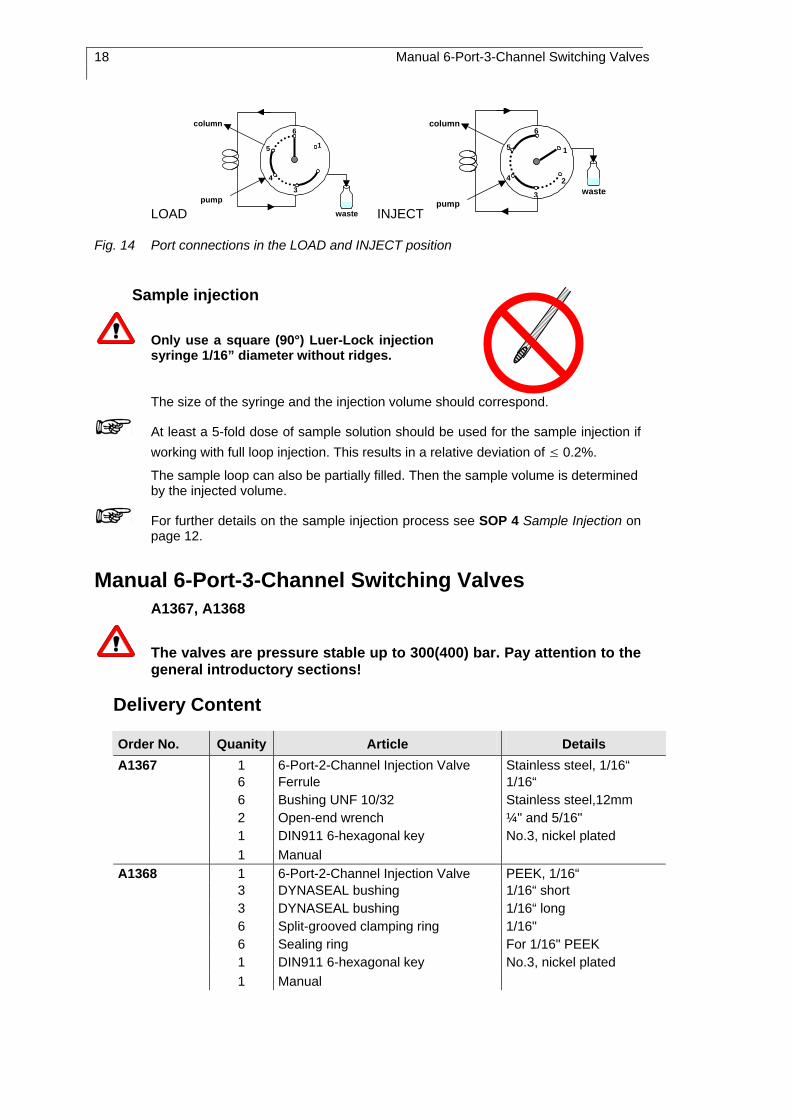
Fig. 14 illustrates the connection of the capillary connections to the individual devices such as the eluent flow through the valve.
18 Manual 6-Port-3-Channel Switching Valves
LOAD
2
6
1
34
5
column
pumpwaste INJECT
column
pumpwaste
6
5 1
2
3
4
Fig. 14 Port connections in the LOAD and INJECT position
Sample injection
Only use a square (90°) Luer-Lock injection syringe 1/16” diameter without ridges.
The size of the syringe and the injection volume should correspond.
At least a 5-fold dose of sample solution should be used for the sample injection if working with full loop injection. This results in a relative deviation of ≤ 0.2%.
The sample loop can also be partially filled. Then the sample volume is determined by the injected volume.
For further details on the sample injection process see SOP 4 Sample Injection on page 12.
Manual 6-Port-3-Channel Switching Valves A1367, A1368
The valves are pressure stable up to 300(400) bar. Pay attention to the general introductory sections!
Delivery Content
Order No. Quanity Article Details A1367 1 6-Port-2-Channel Injection Valve Stainless steel, 1/16“ 6 Ferrule 1/16“ 6 Bushing UNF 10/32 Stainless steel,12mm 2 Open-end wrench ¼" and 5/16"
1 DIN911 6-hexagonal key No.3, nickel plated 1 Manual A1368 1 6-Port-2-Channel Injection Valve PEEK, 1/16“ 3 DYNASEAL bushing 1/16“ short 3 DYNASEAL bushing 1/16“ long 6 Split-grooved clamping ring 1/16" 6 Sealing ring For 1/16" PEEK
1 DIN911 6-hexagonal key No.3, nickel plated 1 Manual

7-Port-1-Channel Valves 19
Layout and Function
These valves completely correspond to the other 6-Port-3-Channel Valves. The manually operated valves differentiate themselves in which they have an elongated rotor axle for feedthrough through the housing of the thermostat. In comparison to the 6-Port-2-Channel Injection Valve there is not an injection port on the 6-Port-3-Channel Valve (see Fig. 12 on page 16).
7-Port-1-Channel Valves A1361, A1362, A1363, A1364 (manually driven) A1373, A1374, A1375, A1376 (electrically driven)
The valves are pressure stable up to 300(400) bar. Pay attention to the general introductory sections!
Delivery Content
Order No. Quanity Article Details A1361 A1373
1 7-Port-1-Channel Switching Valve Stainless steel, 1/16“
7 Ferrule 1/16“ 7 Bushing UNF 10/32 Stainless steel,12mm 2 Open-end wrench 1/4" and 5/16"
1 DIN911 6-hexagonal key No.3, nickel plated 1 Manual A1362 A1374
1 7-Port-1-Channel Switching Valve PEEK, 1/16“
3 DYNASEAL bushing 1/16“ short 4 DYNASEAL bushing 1/16“ long 7 Split-grooved clamping ring 1/16“ 7 Sealing ring For 1/16" PEEK
1 DIN911 6-hexagonal key No.3, nickel plated 1 Manual A1362 A1375
1 7-Port-1-Channel Switching Valve Stainless steel, 1/8“
7 Ferrule 1/8“ 7 Bushing UNF 10/32 Stainless steel,12mm 2 Open-end wrench 1/4" and 5/8"
1 DIN911 6-hexagonal key No.3, nickel plated 1 Manual A1363 A1376
1 7-Port-1-Channel Switching Valve PEEK, 1/8“
7 DYNASEAL Bushing 1/8“ long 7 Split-grooved clamping ring 1/8“ 7 Sealing ring For 1/8" PEEK
1 DIN911 6-hexagonal key No.3, nickel plated 1 Manual

20 7-Port-1-Channel Valves
Layout and Function
The four electrically operated 6-Port-3-Channel Valves are only different in material (stainless steel or PEEK) and/or in the port and a few internal dimensions. As with the 6-Port-3-Channel Valves, according to the operation mode, they are mounted to the Universal Mounting Bracket or to the Smartline Valve Drive 6 or the electrical Valve Drive K-6 (see Fig. 7 on page 11 and SOP 5 on page 14).
Fig. 15 Manual and elektrical operaion of the 7-Port-1-Channel Valve
The manual and electrical valves correspond in construction and functionality with each other. The essential difference is the operating lever that can be turned, clicking into place, 360°. Electrical valves, on the other hand, are moved by a Smartline Valve Drive 6 (Order No. A55020) or Valve Drive K-6 (Order No. A0377). The valves have, therefore, been described together.
All 7-Port Valves can only be switched with an Smartline Valve Drive 6 or Electrical Valve Drive K-6. Operation with a 12 or 16 positions drive results in mechanical malfunctions and may damage the HPLC system.
All 7-Port-1-Channel Switching Valves are identified by the central port 7. This port is connected with one of the six outside ports by turning it in 60° intervals.
1
2
3
4
5
6
7
Fig. 16 The 7-Port-1-Channel Valve switching principle
Examples for using the 7-Port-1-Channel Switching Valves
Step-function gradient As illustrated below, the 7-Port-1-Channel Valve can be used to realise a stepwise gradient for up to 6 eluents.
2
1
3 4
5
6
7
pump
eluents Fig. 17 Stepwise gradient with 6 eluents

7-Port-1-Channel Valves 21
Fraction collector Similarly the 7-Port-1-Channel Valve can also be used as a fraction collector in preparative chromatography (see Fig. 18).
2
HPLC system
1
3 4
5
6
7
fractions
Fig. 18 7-Port-1-Channel Valve as a fraction collector
Column switching By combining two 7-Port-1-Channel Valves a column switching can be realised, in which up to 5 columns and a rinsing line can be involved.
column 5
column 4
column 1
column 3
column 2
purging tube
injectionvalve
detector
1
2
3
4
5
67
1
6
5
4
3
27
Fig. 19 Column switching with two 7-Port-1-Channel Valves
In order to avoid blockage in the pumpby pressure surges, it is important to always synchronously and swiftly switch the valves!

22 17(13)-Port-1-Channel Switching Valves
17(13)-Port-1-Channel Switching Valves A1379, A1379-1, A1378
The valves are pressure stable up to 50(100) bar (17-port) and 25(50) bar (13-port) respectively. Pay attention to the general introductory sections!
Delivery content
Order No. Quanity Article Details A1379 A1379-1
1 17-Port-1-Channel Switching Valve
Stainless steel, 1/16“
17 DYNASEAL Bushing 1/16" long with hexagon 20 Split-grooved clamping ring 1/16" 20 Sealing ring for 1/16", injection molding
polymer 2 Open-end wrench 1/4" and 5/16" 2 Biconical sealing ring 1/16" PETP 1 Manual A1378 1 13-Port-1-Channel Switching
Valve Stainless steel, 1/8“
13 DYNASEAL Bushing 1/8" long with hexagon 15 Split-grooved clamping ring 1/8" 15 Sealing ring for 1/8" injection molding
polymer 2 Open-end wrench 1/4" and 5/16" 2 Biconical sealing ring 1/8" PETP 1 Manual
Layout and Function
The17-Port or 13-Port-1-Channel Switching Valve is operated with the Smartline Valve Drive 16 or 12 alternatively with the Electrical Valve Drive K-16 or K-12. There are no manual versions. The valves correspond, in construction and function, to the 7-Port-1-Channel Switching Valve. The outer ports are arranged in two concentrical circles. Switching from one port to the next occurs in 22.5 or 30° intervals at a time.
The 17-Port Valves can only be switched with an Smartline Valve Drive 16 or Electrical Valve Drive K-16. Operation with a 6 or 12 positions drive results in mechanical malfunctions and may damage the HPLC system.
The 13-Port Valves can only be switched with an Smartline Valve Drive 12 or Electrical Valve Drive K-12. Operation with a 6 or 16 positions drive results in mechanical malfunctions and may damage the HPLC system.
Examples for switching with Multiport Valves 23
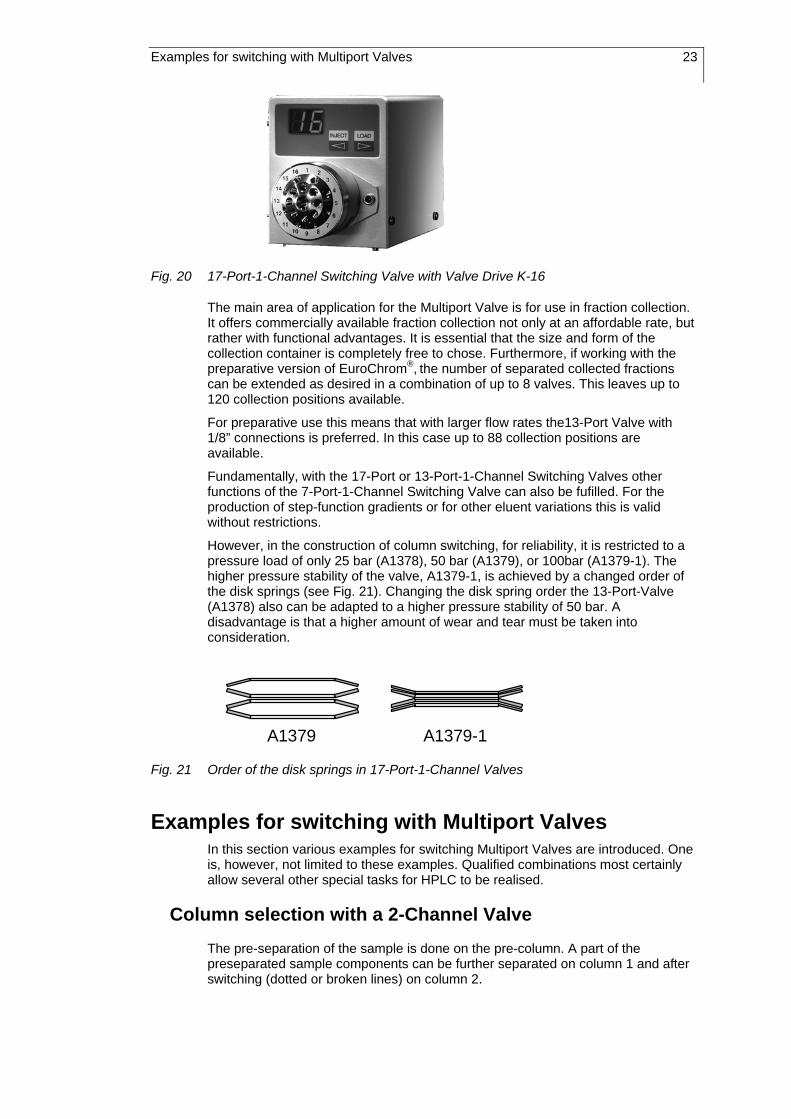
Fig. 20 17-Port-1-Channel Switching Valve with Valve Drive K-16
The main area of application for the Multiport Valve is for use in fraction collection. It offers commercially available fraction collection not only at an affordable rate, but rather with functional advantages. It is essential that the size and form of the collection container is completely free to chose. Furthermore, if working with the preparative version of EuroChrom®, the number of separated collected fractions can be extended as desired in a combination of up to 8 valves. This leaves up to 120 collection positions available.
For preparative use this means that with larger flow rates the13-Port Valve with 1/8” connections is preferred. In this case up to 88 collection positions are available.
Fundamentally, with the 17-Port or 13-Port-1-Channel Switching Valves other functions of the 7-Port-1-Channel Switching Valve can also be fufilled. For the production of step-function gradients or for other eluent variations this is valid without restrictions.
However, in the construction of column switching, for reliability, it is restricted to a pressure load of only 25 bar (A1378), 50 bar (A1379), or 100bar (A1379-1). The higher pressure stability of the valve, A1379-1, is achieved by a changed order of the disk springs (see Fig. 21). Changing the disk spring order the 13-Port-Valve (A1378) also can be adapted to a higher pressure stability of 50 bar. A disadvantage is that a higher amount of wear and tear must be taken into consideration.
A1379 A1379-1
Fig. 21 Order of the disk springs in 17-Port-1-Channel Valves
Examples for switching with Multiport Valves In this section various examples for switching Multiport Valves are introduced. One is, however, not limited to these examples. Qualified combinations most certainly allow several other special tasks for HPLC to be realised.
Column selection with a 2-Channel Valve
The pre-separation of the sample is done on the pre-column. A part of the preseparated sample components can be further separated on column 1 and after switching (dotted or broken lines) on column 2.

24 Examples for switching with Multiport Valves
injection valve
detector
6
1
2
3
4
5
precolumn
column 1
column 2
Fig. 22 Column selection with a 2-Channel Valve
Using a precolumn to precondition the sample
The sample substances are held on a precolumn. After the column switching (dotted or broken line) the sample substances are transported with another eluent or gradient in the analytical separation column.
injection valve
detector
6
1
2
3
4
5
column
precolumn
Fig. 23 Preconditioning the sample using a precolumn and a 2-Channel Valve
Selecting a column with a 3-Channel Valve
Without interrupting the operation, the flow can be switched from column 1 onto column 2 (dotted or broken line).
injection valve
detector
6
1
2
3
4
5
column 2
column 1
Fig. 24 Selecting a column with a 3-Channel Valve
Precolumn back-flushing
Firstly the sample is guided through the precolumn before it reaches the analytical separation column. By switching (dotted or broken line) the columns are rinsed in

Examples for switching with Multiport Valves 25
the opposite order and direction. This ensures that the sample components that were retained on the precolumn are eluted.
injection valvedetector
6
1
2
3
4
5
column
precolumn Fig. 25 Precolumn back-flushing with a 3-Channel Valve
Column back-flushing
After ending a recorded chromatogram, the column will be rinsed in the opposite direction by switching (dotted or broken line). Strongly retarded substances are removed out of the column by back-flushing with another eluent.
injection valvedetector
6
1
2
3
4
5
column Fig. 26 Column back-flushing with a 3-Channel Valve
Sample enrichment
The analysis substances are enriched in the precolumn (dotted or broken line). After switching the valve, the sample is rinsed in the opposite direction of the precolumn with another eluent using a second pump. It is then transferred into the analytical separation column.
detector column
Vorsäule
injection valve
6
1
2
3
4
5
pump 1
pump 2
run off
precolumn
Fig. 27 Column back-flushing with a 3-Channel Valve

26 Examples for switching with Multiport Valves
Alternating enrichment with a precolumn through rinsing
Pump 1 aids the sample over the injection valve to enrichment in precolumn 1. At the same time, the sample previously enriched in precolumn 2 (before the last switch) is transported with the eluent from pump 2 for analysis in the separation column. This process alternates with every switch.
detector 1
injection valve 6
1
2
3
4
5
6
1
2
3
4
5 column
detector 2
pump 1
pump 2 precolumn 2
precolumn 1
Fig. 28 Alternating enrichment and precolumn cleaning with two 3-Channel Valves
In order to avoid blockage in the pump or misalignment, it is important to always synchronously and swiftly switch the valves!
Valves in which two neighboring ports are short circuited by a capillary bridge, can also be replaced with 2-Channel Valves.
Alternating enrichment with precolumn back-flushing
Strongly retarded sample components are enriched on the precolumn. After switching, these components are guided by precolumn back-flushing with another eluent to further separation on the separation column. Due to the fact of two connected precolumns it is possible without interrupting the run to proceed the enrichment alternating and parallel to the separation. For better identification the eluent current of pump 2 is represented with a broken or (after swiching) dotted line.
detector 1
injection valve
6
1
2
3
4
5
6
1
2
3
4
5
detector 2
pump 1
pump 2 column
precolumn 1
precolumn 2
Fig. 29 Alternating enrichment and precolumn back-flushing with two 3-Channel Valves
In order to avoid blockage in the pump or misalignment, it is important to always synchronously and swiftly switch the valves!
Valves in which two neighboring ports are short circuited by a capillary bridge can also be replaced with 2-Channel Valves.

Examples for switching with Multiport Valves 27
Alternating sample preconditioning with precolumn through rinsing
The sample is preconditioned on a precolumn. Only the slightly retarded sample components are transpored to the analytical column and separated there on. After switching, the precolumn is washed with another eluent in order to remove the stronger retarded components. This process alternates between two precolumns.
6
1
2
3
4
5
detector 2 waste injection valve 6
1
2
3
4
5
detector 1
pump 1
pump 2 column
precolumn 1
precolumn 2
Fig. 30 Alternating sample preconditioning and precolumn washing with 3-Channel Valves
In order to avoid blockage in the pump or misalignment by pressure surges, it is important to always synchronously and swiftly switch the valves!
Valves in which two neighboring ports are short circuited by a capillary bridge can also be replaced with 2-Channel Valves.
Alternating sample preconditioning with precolumn back-flushing
The sample is preconditioned on a precolumn. Only the slightly retarded sample components are transpored to the analytical column and separated there on. After switching, the precolumn is washed with another eluent in opposit direction in order to remove the stronger retarded components. This process alternates between two precolumns. For better identification the eluent current of pump 2 is represented with a broken or (after swiching) dotted line.
6
1
2
3
4
5
detector 2
injection valve6
1
2
3
4
5
detector 1
pump 1pump 2
column
precolumn 1
precolumn 2
Fig. 31 Alternating sample preconditioning and precolumn back-flushing with two 3-Channel Valves
In order to avoid blockage in the pump or misalignment by pressure surges, it is important to always synchronously and swiftly switch the valves.
Valves in which two neighboring ports are short circuited by a capillary bridge can also be replaced with 2-Channel Valves.

28 Repair and Service Note
Repair and Service Note SOP 8 Dismantling the valve body
1. Alternately loosen the three imbus mounting screws on the valve. 2. Disassemble the valve in the order shown in the exploded view illustrations
(Fig. 4 and Fig. 13 on pages 10 and 17). 3. Replace the defected parts (i.e. the rotor seal). 4. Reassemble the valve in the opposite order. Pay particular attention to the
correct order and alignment (i.e. disk spring). 5. The proper alignment of the rotor seal on the various valves has been
illustrated in the following table.
Valve Type Assembling position of the rotor seals
1-Channel grading
rotor with sealingrotor
cylindrical pin
Injection Valve
2-Channel
3-Channel
When alternately screwing the valve together the rotor seal will automatically center itself. It is then set by the disk spring level on the stator sealing surface. Adjustment is not necessary.
Due to the special design of the valve, it is not possible to mount the rotor seal obliquely. The result is a long lifespan of the rotor seal and of the entire valve.
Rotor seals with only slight scratches can be smoothed out. Lay a piece of very fine sand paper (i.e. 1000 or rouge) on a smooth base and rub the rotor seal in even circles on it.

Repair and Service Note 29
SOP 9 Inserting a new needle seal in the injection port
1. Remove the needle seal. 2. Push the new needle seal in the bushing. 3. Assemble the needle seal to the split-grooved clamping ring (It is customary
that the old one can be reused) and a new polymer seal. Alternatively, both parts can be replaced with a polymer biconical ring.
4. Slightly tighten the bushing. 5. Insert an injection syringe into the needle seal. 6. Together with the syringe, push the the needle guide to the end of the
injection port. 7. Tighten the bushing enough so that the syringe can still be easily taken out,
however, with considerable friction.
Needle seal DYNASEAL bushing Biconical sealing ring Needle seal
Fig. 32 Injection port with needle seal

30 Accessories and Spare Parts
Accessories and Spare Parts Spare Parts
Item Valve Order No- 6-Port-valves 1/16“ A0611 6-Port-valves 1/8“ G2527 7-Port-valves A0880
Rotor seal
17(13)-Port-valves P3058 Reed contact All valves G0365 Magnetic core All valves M0528
1/16“ Injection-valves P0653 Needle seal 1/8“ Injection-valves P0955
Accessories
Item Order No- Manual V7447 Universal Mounting Bracket A4018 Mounting Bracket for K-120 A0406 Analytical sample loop
1/16“, stainless steel 5, 10, 20, 30, 50, 75, 100, 200, 500, 1000, 2000µl
1/16“ PEEK 10, 20, 50, 200, 500µl
Preparative sample loop 1/8“, stainless steel or PEEK
1, 2, up to 11, up to 45ml 1/16“, stainless steel or PEEK
up to 11, up to 45ml
Injection syringes 10, 25, 50, 100, 250, 500, 1000, 2500µl
A0723-A0730

Zur Benutzung des Handbuches 31
Zur Benutzung des Handbuches
Besondere Warnhinweise und Hinweise auf mögliche Probleme sind mit dem Warnsymbol gekennzeichnet.
Wichtige Hinweise werden in der Marginalspalte durch das Hinweissymbol kenntlich gemacht.
Ein nützlicher Tip wird in der Marginalspalte durch das Symbol hervorgehoben.
Standardarbeitsanweisungen in diesem Handbuch Die Standardarbeitsanweisungen (Standard Operating Procedures, SOP) dieses Handbuches ermöglichen die Strukturierung zusammenhängender Aufgaben beim Betrieb ihrer Injektions- und Schaltventile. Sie beinhalten schrittweise Anweisungen, die den Anwender durch alle Aufgaben führen. Sie können gleichfalls zu Dokumentationszwecken genutzt werden. Sie können kopiert, angewendet, unterzeichnet und hinterlegt werden, um so die Leistungsfähigkeit Ihrer Ventile zu dokumentieren.
Bitte betreiben Sie die Ventile gemäß den SOPs in diesem Handbuch. Andernfalls können fehlerhafte Ergebnisse, Beschädigungen oder gesundheitliche Beeinträchtigungen des Anwenders nicht ausgeschlossen werden, obwohl die Ventile außerordentlich robust und betriebssicher sind.
Tabelle 1 Liste der SOPs dieses Handbuches
SOP 1 Anschluss einer Kapillare mittels DYNASEAL-Verschraubung 34 SOP 2 Anschluss einer Kapillare mittels UNF-Verschraubung 34 SOP 3 Anschlüsse an ein 6-Port-3-Kanal-Injektionsventil 38 SOP 4 Probeninjektion 39 SOP 5 Ventilmontage an den elektrischen Antrieb 41 SOP 6 Einbau des Ventils in den Thermostaten 44 SOP 7 Anschlüsse an ein 6-Port-2-Kanal-Injektionsventil 44 SOP 8 Demontage der Ventilkörper 55 SOP 9 Einsetzen einer neuen Nadeldichtung in den Spritzenport 56

32 Zur Benutzung des Handbuches
Dieses Handbuch bezieht sich auf alle in der folgenden Tabelle aufgeführten KNAUER Injektions- und Schaltventile.
Tabelle 2 Liste der KNAUER Injektions- und Schaltventile
Bestell Nr. Ports Kanäle Funktion Material Anschluss Antrieb
A1357 6 3 Injektion Schalten Edelstahl 1/16" manuell
A1358 6 3 Injektion Schalten PEEK 1/16" manuell
A1359 6 3 Injektion Schalten Edelstahl 1/8" manuell
A1360 6 3 Injektion Schalten PEEK 1/8" manuell
A1361 7 1 Schalten Edelstahl 1/16" manuell A1362 7 1 Schalten PEEK 1/16" manuell A1363 7 1 Schalten Edelstahl 1/8" manuell A1364 7 1 Schalten PEEK 1/8" manuell A1365 6 2 Injektion Edelstahl 1/16" manuell1) A1366 6 2 Injektion PEEK 1/16" manuell1) A1367 6 3 Schalten Edelstahl 1/16" manuell1) A1368 6 3 Schalten PEEK 1/16" manuell1)
A1369 6 3 Injektion Schalten Edelstahl 1/16" K-6
A1369-1 6 2 Schalten Edelstahl 1/16" K-6
A1370 6 3 Injektion Schalten PEEK 1/16" K-6
A1371 6 3 Injektion Schalten Edelstahl 1/8" K-6
A1371-1 6 2 Injektion Schalten Edelstahl 1/8" K-6
A1372 6 3 Injektion Schalten PEEK 1/8" K-6
A1373 7 1 Schalten Edelstahl 1/16" K-6 A1374 7 1 Schalten PEEK 1/16" K-6 A1375 7 1 Schalten Edelstahl 1/8" K-6 A1376 7 1 Schalten PEEK 1/8" K-6 A1378 13 1 Schalten Edelstahl 1/8" K-12
1) zum Einbau in den Säulenthermostaten A0585

Allgemeines 33
Allgemeines Alle KNAUER Injektions- und Schaltventile werden standardmäßig in der HPLC eingesetzt. Die Ventile gibt es sowohl in Edelstahl- als auch in Polymerausführung (PEEK). Bei den PEEK-Ventilen kommt die Probe und der Eluent ausschließlich mit dem Polymer in Kontakt. Dadurch ist die Voraussetzung für ein inertes Arbeiten gegeben.
Die Ventile sind grundsätzlich bis zu einem Daurerarbeitsdruck von 300 bar ausgelegt. Auf Anforderung können sie auch mit einer Druckstabilität bis 400 bar ausgeliefert werden. Ein nachträgliches Umrüsten durch unsere Serviceabteilung ist ebenfalls möglich.
Die Mehrkanal Injektions- und Schaltventile sind mit einem Reed-Kontakt und Magnet ausgestattet. Dieser bewirkt, dass beim Schalten des Ventils in die INJECT Position ein kontakt geschlossen wird, der beim Schalten in die LOAD Position wieder geöffnet wird.
Der Reed-Kontakt wird meist verwendet, um ein Startsignal für die HPLC-Software oder für einen Integrator zu geben oder bei Detektoren mit jeder Injektion die Basislinie durch ein Autozero automatisch zu korrigieren.
Falls statt eines Dauerkontaktes ein Puls gewünscht wird, kann ein Pulsgeber (Bestellnummer A1137) eingesetzt werden. Dieser erzeugt einen Puls beim Schalten von LOAD auf INJECT, jedoch nicht beim entgegengesetzten Schalten von INJECT auf LOAD.
Weitere Details zum Reed-Kontakt finden Sie in den Abschnitten zu den einzelnen Ventilgruppen und in den Handbüchern der zu steuernden Geräte.
Die Ventile sollen nicht in trockenem Zustand betrieben werden, da sonst die Lebendauer der Rotordichtung reduziert wird. Das gilt insbesondere für die motorgetriebenen Ventile.
Bei der Verwendung von wässrigen Salz- oder Pufferlösungen empfielt es sich, nach dem Gebrauch das Ventil mit destilliertem Wasser und/oder Methanol zu spülen. Dadurch wird die Bildung von Salzkristallen im Ventil verhindert.
Das Umschalten der Ventile muss immer zügig erfolgen, um ein Blockieren der Pumpe durch große Druckstöße zu vermeiden!

34 Kapillar-Verbindungen
Kapillar-Verbindungen Grundsätzlich können die Kapillar-Verbindungen von und zu den Injektions- oder Schaltventilen sowohl mit Edelstahl- als auch mit PEEK Kapillaren hergestellt werden. Die Befestigung ist generell mit DYNASEAL-VERSCHRAUBUNGen möglich. Stahlkapillaren sollten jedoch besser mit den beiliegenden UNF-Verschraubungen dauerhaft befestigt werden.
Benutzen Sie, um Beschädigungen zu vermeiden, keine Stahl-verbindungsteile für die Ventile in PEEK-Bauweise. Verwenden Sie stattdessen nur PEEK-Kapillaren, Zangenklemmringe, PEEK-Dichtringe und DYNASEAL-Verschraubungen. Die DYNASEAL-Verschraubungen dürfen nur von Hand angezogen werden.
Generell ist darauf zu achten, dass alle Kapillar-Verbindungen totvolumenarm hergestellt werden. Verwenden Sie deshalb möglichst kurze Kapillaren mit kleinem Innendurchmesser.
Die Abb. 1 zeigt das Prinzip der UNF- und der DYNASEAL-Verschraubungen.
Verschraubung
ZangenklemmringPEEK DichtringKapillare
UNF DYNASEAL
Verschraubung
SchneidringKapillare
Abb. 1 Prinzip der UNF- und DYNASEAL-Verschraubungen
Beide Verschraubungsarten gibt es sowohl in einer Kurzkopf- als auch einer Langkopfausführung. Die Auswahl ist in keinem Fall funktionsbedingt. Sie ist vielmehr aufgrund der örtlichen geometrtischen Verhältnisse zu treffen.
Die Zugänglichkeit der einzelnen Verschraubungen kann oft dadurch optimiert werden, dass die beiden Verschraubungsformen alternierend eingesetzt werden.
SOP 1 Anschluss einer Kapillare mittels DYNASEAL-Verschraubung
1. Vergewissern Sie sich, dass das Kapillarende glatt und rechtwinklig zur Kapillarachse ist. Gegebenenfalls kürzen Sie die Kapillare mittels eines Schlauchschneiders (Bestellnummer A0569).
2. Stecken Sie die Verschraubung, den Zangenschneidring und den Dichtring auf die Kapillare. Achten Sie auf Reihenfolge und Ausrichtung der Fittings, siehe Abb. 1.
3. Schieben Sie die Kapillare bis zum Anschlag in den Ventilport ein.
4. Ziehen Sie bei leichtem Druck auf die Kapillare die Verschraubung mit den Fittings handfest an, siehe Abb. 2.
SOP 2 Anschluss einer Kapillare mittels UNF-Verschraubung
1. Vergewissern Sie sich, dass das Kapillarende glatt und rechtwinklig zur Kapillarachse ist. Gegebenenfalls kürzen Sie die Kapillare mittels einer

Manuell betriebene 6-Port-3-Kanal-Ventile 35
Kapillarschneidzange (Bestellnummer A0569) und entgraten Sie mit dem Entgratungsdorn (Bestellnummer A0137).
2. Stecken Sie die Verschraubung und den Schneidring auf die Kapillare. Achten Sie auf Reihenfolge und Ausrichtung der Fittings, siehe Abb. 1.
3. Schieben Sie die Kapillare bis zum Anschlag in den Port ein. 4. Ziehen Sie bei leichtem Druck auf die Kapillare die Verschraubung mit dem
Schneidring zunächst handfest an, siehe Abb. 2. 5. Ziehen Sie die Verschraubung mit einem Sechskantschlüssel nach.
richtig falsch
Totvolumen undicht
Abb. 2 Sitz der Kapillarverbindungen
Manuell betriebene 6-Port-3-Kanal-Ventile A1357, A1358, A1359, A1360
Die Ventile sind bis 300/400 bar druckstabil. Beachten Sie auch die vorangestellten, alle Ventile betreffenden Abschnitte!
Lieferumfang
Best. Nr. Stück Artikel Details A1357 1 6-Port-3-Kanal-Injektionsventil Edelstahl, 1/16“ 4 Schneidring 1/16“ 1.4401 2 Doppelkonus-Dichtring 1/16“ PETP 1 Verschraubung UNF 10/32 Edelstahl lg. 12mm 3 Verschraubung UNF 10/32 15mm 2 Maulschlüssel 1/4" und 5/16" 2 Nadeldichtung 34mm AD1,6 x ID 0,9mm 1 DIN911 6-Kantschlüssel Nr.3 vernickelt 1 Handbuch A1358 1 6-Port-3-Kanal-Injektionsventil PEEK, 1/16“ 1 Doppelkonus-Dichtring 1/16“ PETP 4 Zangenklemmring 1/16“ 4 Dichtring für 1/16“ PEEK 4 DYNASEAL-Verschraubung 1/16“ lang 2 Nadeldichtung 34mm AD1,6xID0,9mm 1 DIN911 6-Kantschlüssel Nr.3, vernickelt 1 Handbuch

36 Manuell betriebene 6-Port-3-Kanal-Ventile
Best. Nr. Stück Artikel Details A1359 1 6-Port-3-Kanal-Injektionsventil Edelstahl, 1/8“ 6 Verschraubung 1/8“ M8x1 SW10
6 Schneidring 1/8“ 2 Maulschlüssel 8/10" 1 DIN911 6-Kantschlüssel Nr.3, vernickelt 1 DYNASEAL-Verschraubung 1/8“ lg. M8x1 1 Doppelkonusdichtring 1/8“ PETP 2 Nadeldichtung 1/8“ 37mm AD1/8“ x ID1,5mm 1 Einmalspritze 10ml, Lueranschluß 1 Luer-Lock-Kanüle 1,5x50, stumpf
1 Handbuch A1360 1 6-Port-3-Kanal-Injektionsventil PEEK, 1/8“
6 DYNASEAL-Verschraubung 1/8"lg. M8x1 6 Dichtring für 1/8" PEEK 1 Nadeldichtung 1/8" 37mm AD1/8"xID1,5 6 Zangenklemmring 1/8" 1 Doppelkonusdichtring 1/8" PETP 1 Einmalspritze 10ml Lueranschluß 1 Luer-Lock-Kanüle 1,5x50 stumpf 1 DIN911 6Kantschlüssel Nr.3 vernickelt
1 Handbuch
Aufbau und Funktion
Die vier manuell betriebenen 6-Port-3-Kanal-Ventile unterscheiden sich nur im Material (Edelstahl bzw. PEEK) und/oder in der Portdimensionen und einigen internen Dimensionen. Sie werden deshalb gemeinsam beschrieben.
Der Ventilkörper enthält in seinem Gehäuse einen Rotor der über automatisch justierenden Tellerfedern, Anlaufscheiben und einem Axial-Nadellager im Gehäuse ruht. Mit dem Rotor ist ein senkrecht zur Rotorachse geführter Hebel verschraubt, mit dem der Rotor bewegt werden kann. Durch eine Aussparung im Gehäuse ist die Drehbewegung auf 60° beschränkt. In das Gehäuse ist ein Reed-Kontakt für die Positionserkennung des Rotors eingelassen. Er wird von einem Magneten angesprochen, der im Ring des Hebels sitzt. Auf dem Rotor befindet sich die Rotordichtung.
Abb. 3 Manuell bedientes 6-Port-3-Kanalventil

Manuell betriebene 6-Port-3-Kanal-Ventile 37
Deckel O-Ring Gleitring Senkschrauben Magnet Hebel Rotordichtung Rotor Tellerfedern Ausgleichsscheibe Laufscheibe Axial-Nadellager Axialscheibe Zylinderstift Gehäuse Imbusschrauben
Abb. 4 Explosionsdarstellung 6-Port-3-Kanalventil
Mit dem Hebel kann der Rotor um 60° verstellt werden :
Hebel links: LOAD-Stellung Hebel rechts: INJECT-Stellung
In der INJECT-Stellung spricht der Magnet den Reed-Kontakt an. Durch das Schließen des Kontaktes kann z.B. ein Gradientenprogrammer oder ein Detektor gestartet werden. Je nach Stellung des Rotors werden durch die eingefrästen Kanäle in der Rotordichtung unterschiedliche benachbarte Ports verbunden, Abb. 5.
LOAD INJECT
Abb. 5 Portverbindungen in LOAD- und INJECT-Stellung
In der LOAD-Position wird die Probenschleife gefüllt. Beim Umschalten in die INJECT-Position wird die Probe in das System injiziert. Dabei durchfließt der Eluent die Probenschleife in entgegengesetzter Richtung, um die Bandenverbreiterung zu minimieren. Dies ist insbesondere bei partiellen Füllungen der Probenschleife von Vorteil.

38 Manuell betriebene 6-Port-3-Kanal-Ventile
Probe Eluent
Abb. 6 Fließrichtungen beim Beladen (Probe) und Injizieren (Eluent)
Installation
Zur Befestigung der Ventile an Instrumenten dient der Universalwinkel (A4018), der durch die Langlöcher in seinem kurzen Schenkel an die an allen KNAUER Pumpen seitlich vorhanden M4 Gewindebohrungen angeschraubt werden kann.
Für die HPLC-Pumpe K-120 muß ein speziell für diese Pumpe geeigneter Winkel (A0406) verwendet werden.
1
3
2
Abb. 7 Universalwinkel zur Ventilbefestigung
Das Ventil wird durch die beiden Bohrungen (1) seiltich der Großbohrung mit M4 Schrauben befestigt. Hierzu dienen die beiden Gewindebohrungen auf der Ventilrückseite.
Die Bohrungen (2) dienen als Kapillardurchführungen und an Position (3) ist der auf der Rückseite befindliche Säulenträger befestigt.
Der Anschluss der Kapillaren ist im alle Ventile betreffenden Abschnitt Kapillar-Verbindungen auf Seite 33 beschrieben. Die Zuordnung der Anschlüsse ist von der vorgesehenen Betriebsart abhängig und ist deshalb im folgenden Abschnitt beschrieben.
Inbetriebnahme und Bedienung
Verwendung als Injektionsventil Zur Verwendung des Ventils als Injektionsventil ist in den Port 1 ein Spritzenport einzuschrauben, der aus einer DYNASEAL-Verschraubung mit Nadeldichtung besteht, siehe Abb. 32 auf Seite 56.
SOP 3 Anschlüsse an ein 6-Port-3-Kanal-Injektionsventil
1. Setzen Sie den Spritzenport in Port 1 des Ventils ein und ziehen Sie die Verschraubung von Hand leicht an.
2. Führen Sie eine Injektionsspritze in die Nadeldichtung ein.
5 Bohrung für Ventilbefestigung 6 Kapillardurchführungen 7 Säulenbefestigung

Manuell betriebene 6-Port-3-Kanal-Ventile 39
3. Schieben Sie die Nadelführung mit der Spritze bis zum Anschlag in den Spritzenport ein.
4. Ziehen Sie die Verschraubung moderat so stark an, dass sich die Spritze noch leicht aber mit spürbarer Reibung herausnehmen läßt.
5. Die Probenschleife wird diagonal an Port 2 und Port 5 angeschlossen. 6. Verbinden Sie die Pumpe mit Port 4. 7. Port 6 wird durch einen Teflonschlauch oder eine Kapillare mit einer
Abfallflasche verbunden.
Es ist vorteilhaft, den Auslauf etwa in Höhe des Spritzenports zu halten, um eine Saugwirkung durch die Höhendifferenz zu vermeiden.
8. Spülen Sie das Ventil mit dem Eluenten. 9. Schließen Sie nach dem Spülen die Säule an Port 3 an.
Injektion einer Probe
Benutzen Sie nur eine Luer-Lock-Injektionsspritze mit gratfreier und flach geschliffener 1/16“ Kanüle (90°).
Die Spritze soll in Ihrer Größe dem Injektionsvolumen angepasst sein.
Verwenden Sie für die Full Loop Probeninjektion mindestens einen 5fachen Überschuss der Probenlösung. Dadurch erreichen Sie eine relative Abweichung von ≤ 0,2%.
Die Probenschleife kann auch partiell gefüllt werden. Das Injektionsvolumen wird dann durch die eingespritzte Menge bestimmt.
SOP 4 Probeninjektion
1. Stellen Sie das Ventil auf LOAD. 2. Nehmen Sie die Probe in die Spritze auf und entfernen Sie in der Spritze
eventuell befindliche Luftblasen. 3. Führen Sie die Spritze bis zum Anschlag in den im Port 1 befindlichen
Spritzenport. 4. Entleeren Sie die Spritze in die Probenschleife und belassen Sie sie im Port. 5. Schalten Sie das Ventil auf inject. Starten Sie gegebenenfalls gleichzeitig die
Datenaufnahme. 6. Stellen Sie das Ventil auf LOAD und ziehen Sie die Spritze aus dem
Einlassport. 7. Spülen Sie gegebenenfalls den Einlassport und die Probenschleife mit dem
Eluenten (In der Regel nur in der Spurenanalytik erforderlich, da die Kontamination vernachlässigbar klein ist).
Das Umschalten der Ventile muss immer zügig erfolgen, um ein Blockieren der Pumpe durch große Druckstöße zu vermeiden!
Verwendung als Schaltventil Die vier manuell betriebenen 6-Port-3-Kanal-Ventile können auch für vielfältige Schaltfunktionen eingesetzt werden. Details hierzu finden Sie im Abschnitt Schaltbeispiele mit Mehrkanalventilen auf Seite 50. In diesem Abschnitt werden Schaltmöglichkeiten der 2- und 3-Kanalventile dargestellt. Für diese Darstellung ist auch eine Unterscheidung der manuell und der elektrisch betriebenen Schaltventile nicht erforderlich.

40 Elektrisch betriebene 6-Port-3-Kanal-Ventile
Elektrisch betriebene 6-Port-3-Kanal-Ventile A1369, A1370, A1371, A1372
Die Ventile sind bis 300/400 bar druckstabil. Beachten Sie auch die vorangestellten, alle Ventile betreffenden Abschnitte!
Lieferumfang
Best. Nr. Stück Artikel Details A1369 A1369-1
1 6-Port-3-Kanal-Injektionsventil (6-Port-2-Kanal-Schaltventil)
Edelstahl, 1/16“
8 Schneidring 1/16“ 2 Doppelkonus-Dichtring 1/16“ PETP 3 Verschraubung UNF 10/32 Edelstahl lg. 12mm 3 Verschraubung UNF 10/32 15mm 2 Maulschlüssel 1/4" und 5/16" 2 Nadeldichtung 34mm AD1,6 x ID 0,9mm 1 Handbuch A1370 1 6-Port-3-Kanal-Injektionsventil PEEK, 1/16“ 1 Doppelkonus-Dichtring 1/16“ PETP 4 Zangenklemmring 1/16“ 4 Dichtring für 1/16“ PEEK 4 DYNASEAL-Verschraubung 1/16“ lang 2 Nadeldichtung 34mm AD1,6xID 0,9mm 1 DIN911 6-Kantschlüssel Nr.3, vernickelt 1 Handbuch A1371 A1371-1
1 6-Port-3-Kanal-Injektionsventil (6-Port-2-Kanal-Ventil)
Edelstahl, 1/8“
6 Verschraubung 1/8“ M8x1 SW10 6 Schneidring 1/8“ 2 Maulschlüssel 8/10" 1 DIN911 6-Kantschlüssel Nr.3, vernickelt 1 DYNASEAL-Verschraubung 1/8“ lg. M8x1 1 Doppelkonusdichtring 1/8“ PETP 2 Nadeldichtung 1/8“ 37mm AD1/8“ x ID1,5mm 1 Einmalspritze 10ml, Lueranschluß 1 Luer-Lock-Kanüle 1,5x50, stumpf
1 Handbuch A1372 1 6-Port-3-Kanal-Injektionsventil PEEK, 1/8“
6 DYNASEAL-Verschraubung 1/8"lg. M8x1 6 Dichtring für 1/8" PEEK 1 Nadeldichtung 1/8" 37mm AD1/8"xID1,5 6 Zangenklemmring 1/8" 1 Doppelkonusdichtring 1/8" PETP 1 Einmalspritze 10ml Lueranschluß 1 Luer-Lock-Kanüle 1,5x50, stumpf 1 DIN911 6-Kantschlüssel Nr.3, vernickelt
1 Handbuch

Elektrisch betriebene 6-Port-3-Kanal-Ventile 41
Aufbau und Funktion
Die vier elektrisch betriebenen 6-Port-3-Kanal-Ventile unterscheiden sich nur im Material (Edelstahl bzw. PEEK) und/oder in der Port- und einigen internen Dimensionen. Sie werden deshalb gemeinsam beschrieben.
Abb. 8 7-Port-1-Kanal-Ventil mit Ventilantrieb K-6 Der Aufbau und die Funktionsweise entspricht weitestgehend dem der manuell betriebenen Ventile, siehe Seite 35. Der wesentliche Unterschied ist der nicht vorhandene Bedienungshebel. Die Ventile werden vielmehr durch die elektrischen Ventilantriebe Smartline Valve Drive 6 (Bestellnummer A55020) oder K-6 (Bestellnummer A0377) bewegt.
SOP 5 Ventilmontage an den elektrischen Antrieb
1. Überprüfen Sie die DIP-Schalterstellung an Ihrem Smartline Valve Drive 6 oder elektrischen Ventilantrieb K-6, siehe Handbuch zum Ventilantrieb, und korrigieren Sie diese gegebenenfalls.
2. Schrauben Sie die Adapterscheibe mit den beiden M4-Senkschrauben auf die Ventilrückseite.
3. Stellen Sie den Antrieb auf die Position 1 bzw. LOAD. 4. Stecken Sie das Ventil auf die Antriebsachse des elektrischen Ventilantriebs
an der Gerätefrontseite. 5. Beachten Sie dabei, dass die Körnung auf der Ventilrückseite über
derjenigen auf der Antriebsachse liegt. Der Ventilport 1 muss nach oben ausgerichtet sein.
6. Befestigen Sie die Adapterscheibe mit den beiden M4-Imbusschrauben am Gehäuse.
Alle 6-Port-Ventile dürfen nur mit dem Smartline Valve Drive 6 oder elektrischen Ventilantrieb K-6 geschaltet werden. Der Betrieb mit einem 12-oder 16- Positionsantrieb hat Blockierungen des Eluentenstroms zur Folge und kann daher zu Schäden an Ihrem HPLC-System führen.
Die Abb. 9 veranschaulicht den Anschluss der Kapillarverbindungen zu den einzelnen Geräten sowie den Eluentenfluss durch das Ventil.
LOAD INJECT
Abb. 9 Portverbindungen in LOAD- und INJECT-Stellung

42 Elektrisch betriebene 6-Port-3-Kanal-Ventile
Verwendung als Injektionsventil Der Funktion der elektisch betriebenen Injektionsventile entspricht dem der manuell betriebenen.
Zur Herstellung der Capillarverbindungen verfahren Sie nach der SOP 3 Anschlüsse an ein 6-Port-3-Kanal-Injektionsventil auf Seite 38.
Injektion einer Probe
Benutzen Sie nur eine Luer-Lock-Injektionsspritze mit gratfreier und flach geschliffener 1/16“ Kanüle (90°).
Die Spritze soll in Ihrer Größe dem Injektionsvolumen angepasst sein.
Verwenden Sie für die Full-Loop-Probeninjektion mindestens einen 5-fachen Überschuss der Probenlösung. Dadurch erreichen Sie eine relative Abweichung von ≤ 0,2%.
Die Probenschleife kann auch partiell gefüllt werden. Das Injektionsvolumen wird dann durch die eingespritzte Menge bestimmt.
Zur Probeninjektion verfahren Sie nach SOP 4 Probeninjektion auf Seite 39.
6 2
5 3
1
4
Probenreservoir
Eluentenreservoir Säule
Hauptpumpe Feedpumpe
Abb .10 Anschlüsse für Feedpumpeninjektion ohne Probenschleife
Verwendung als Schaltventil Die vier manuell betriebenen 6-Port-3-Kanal-Ventile können auch für vielfältige Schaltfunktionen eingesetzt werden. Details hierzu finden Sie im Abschnitt Schaltbeispiele mit Mehrkanalventilen auf Seite 50. In diesem Abschnitt werden Schaltmöglichkeiten der 2- und 3-Kanalventile dargestellt. Für diese Darstellung ist eine Unterscheidung der manuell und der elektrisch betriebenen Schaltventile nicht erforderlich.
Sonderausführung als 6-Port-2-Kanalventil Durch Ausbau der Rotordichtung und deren Drehung um 180° quer zur Rotorachse vor dem Wiedereinbau, wird aus den 3-Kanalventilen ein 2-Kanalventil (A1369-1; A1371-1). Der Lieferumfang entspricht dem des jeweiligen 3-Kanalventils.
INJECT
6 2
5 3
1
4 LOAD
6 2
5 3
1
4
Abb .11 Intern verbundene Ports in Abhängigkeit von der Ventilstellung

Manuelle 6-Port-2-Kanal-Einbauinjektionsventile 43
Manuelle 6-Port-2-Kanal-Einbauinjektionsventile A1365, A1366
Die Ventile sind bis 300/400 bar druckstabil. Beachten Sie auch die vorangestellten, alle Ventile betreffenden Abschnitte!
Lieferumfang
Best. Nr. Stück Artikel Details A1365 1 6-Port-2-Kanal-Einbauinjektionsventil Edelstahl, 1/16“ 4 Schneidring 1/16“ 4 Verschraubung UNF 10/32 Edelstahl lg. 12mm 2 Maulschlüssel 1/4" und 5/16"
1 DIN911 6-Kantschlüssel Nr.3, vernickelt 1 Handbuch A1366 1 6-Port-2-Kanal-Einbauinjektionsventil PEEK, 1/16“ 4 DYNASEAL-Verschraubung 1/16“ lang 4 Zangenklemmring 1/16" Edelstahl lg. 12mm 4 Dichtring für 1/16" PEEK 1 Handbuch
Aufbau und Funktion
Die beiden manuell betriebenen 6-Port-2-Kanal-Ventile wurden speziell für den Einbau in den Säulenthermostaten (Bestellnummer A0585) konzipiert. Sie unterscheiden sich voneinander nur im Material (Edelstahl bzw. PEEK) und werden deshalb auch gemeinsam beschrieben.
Abb. 12 6-Port-2-Kanal-Einbauinjektionsventil
Der wesentliche Unterschied zu den 6-Port-3-Kanalventilen besteht darin, dass der Spritzenport durch den verlängerten Rotor aus dem Thermostaten herausgeführt wird. Aus diesem Grunde muss ein längerer Spritzenport verwendet werden, Abb. 13.
Spritzenport

44 Manuelle 6-Port-2-Kanal-Einbauinjektionsventile
Spritzenport
Imbusschrauben
Hebel
Gehäuse
ZylinderstiftAnlaufscheibeAxial-NadellagerAnlaufscheibeAusgleichsscheibenTellerfedern
Rotor
RotordichtungPositionierscheibeMagnetSenkschrauben
O-RingGleitring
Deckel
Abb. 13 Explosionsdarstellung 2-Kanal Injektionsventile
SOP 6 Einbau des Ventils in den Thermostaten
1. Schrauben Sie den Spritzenport heraus. 2. Lösen Sie den Hebel vom Ventil, indem Sie die beiden Schrauben entfernen 3. Führen Sie die Rotorachse von innen durch die Aussparung in der
Thermostatenoberseite. 4. Schrauben Sie das Ventil an der Thermostatenoberseite mit zwei
M4 Schrauben fest. 5. Montieren Sie den Hebel wieder auf die Achse. 6. Schrauben Sie den Spritzenport in die in der Hebelachse befindliche
Bohrung. 7. Führen Sie die Reed Kontaktanschlüsse durch eine der an der Seite
befindlichen Kapillardurchführungen nach außen. SOP 7 Anschlüsse an ein 6-Port-2-Kanal-Injektionsventil
1. Setzen Sie den Spritzenport in den Außenport des Ventils ein und ziehen Sie die Verschraubung von Hand leicht an.
2. Die Probenschleife wird diagonal an Port 3 und Port 6 angeschlossen. 3. Verbinden Sie die Pumpe mit Port 4. 4. Die Ports 1 und 2 werden durch Teflonschläuche oder Kapillaren mit einer
Abfallflasche verbunden.
Es ist vorteilhaft, den Auslauf etwa in Höhe des Spritzenports zu halten, um eine Saugwirkung durch die Höhendifferenz zu vermeiden.
7. Spülen Sie das in LOAD befindliche Ventil mit dem Eluenten. 8. Schließen Sie nach dem Spülen die Säule an Port 5 an.
Die Verbindungen von der Pumpe, zum Detektor und zum Abfallsammelgefäß werden durch die an der Seite des Thermostaten befindlichen Kapillardurchführugen geführt.
Abb. 14 veranschaulicht den Anschluss der Kapillarverbindungen zu den einzelnen Geräten sowie den Eluentenfluss durch das Ventil.

Manuelle 6-Port-3-Kanal-Einbauschaltventile 45
LOAD
Säule
Pumpe
Abfall
6
1
2
34
5
INJECT
Säule
PumpeAbfall
6
1
2
3
4
5
Abb. 14 Portverbindungen in LOAD- und INJECT-Stellung
Injektion einer Probe
Benutzen Sie nur eine Luer-Lock-Injektionsspritze mit gratfreier und flach geschliffener 1/16“ Kanüle (90°).
Die Spritze soll in Ihrer Größe dem Injektionsvolumen angepasst sein.
Verwenden Sie für die Full Loop Probeninjektion mindestens einen 5fachen Überschuss der Probenlösung. Dadurch erreichen Sie eine relative Abweichung von ≤ 0,2%.
Die Probenschleife kann auch partiell gefüllt werden. Das Injektionsvolumen wird dann durch die eingespritzte Menge bestimmt.
Zur Probeninjektion verfahren Sie nach SOP 4 Probeninjektion auf Seite 39.
Manuelle 6-Port-3-Kanal-Einbauschaltventile A1367, A1368
Die Ventile sind bis 300/400 bar druckstabil. Beachten Sie auch die vorangestellten, alle Ventile betreffenden Abschnitte!
Lieferumfang
Best. Nr. Stück Artikel Details A1367 1 6-Port-2-Kanal-Einbauinjektionsventil Edelstahl, 1/16“ 6 Schneidring 1/16“ 6 Verschraubung UNF 10/32 Edelstahl lg. 12mm 2 Maulschlüssel 1/4" und 5/16"
1 DIN911 6-Kantschlüssel Nr.3, vernickelt 1 Handbuch A1368 1 6-Port-2-Kanal-Einbauinjektionsventil PEEK, 1/16“ 3 DYNASEAL-Verschraubung 1/16“ kurz 3 DYNASEAL-Verschraubung 1/16“ lang 6 Zangenklemmring 1/16" 6 Dichtring für 1/16" PEEK
1 DIN911 6-Kantschlüssel Nr.3, vernickelt 1 Handbuch

46 7-Port-1-Kanal-Schaltventile
Aufbau und Funktion
Diese Ventile entsprechen in Ihrer Funktion vollständig den anderen 6-Port-3-Kanal-Ventilen. Von den manuell betriebenen Ventilen (A1357, A1358, A1359, A1360) unterscheiden sie sich durch die verlängerte Rotorachse als Durchführung durch das Thermostatengehäuse. Im Unterschied zu den 6-Port-2-Kanal-Einbauinjektionsventilen haben Sie keinen nach außen gezogenen Spritzenport, vergl. Abb. 18 auf Seite 48.
7-Port-1-Kanal-Schaltventile A1361, A1362, A1363, A1364 (manuell) A1373, A1374, A1375, A1376 (elektrisch)
Die Ventile sind bis 300/400 bar druckstabil. Beachten Sie auch die vorangestellten, alle Ventile betreffenden Abschnitte!
Lieferumfang
Best. Nr. Stück Artikel Details A1361 A1373
1 7-Port-1-Kanal-Schaltventil Edelstahl, 1/16“
7 Schneidring 1/16“ 7 Verschraubung UNF 10/32 Edelstahl lg. 12mm 2 Maulschlüssel 1/4" und 5/16"
1 DIN911 6-Kantschlüssel Nr.3, vernickelt 1 Handbuch A1362 A1374
1 7-Port-1-Kanal-Schaltventil PEEK, 1/16“
3 DYNASEAL-Verschraubung 1/16“ kurz 4 DYNASEAL-Verschraubung 1/16“ lang 7 Zangenklemmring 1/16“ 7 Dichtring für 1/16" PEEK
1 DIN911 6-Kantschlüssel Nr.3, vernickelt 1 Handbuch A1363 A1375
1 7-Port-1-Kanal-Schaltventil Edelstahl, 1/8“
7 Schneidring 1/8“ 7 Verschraubung UNF 10/32 Edelstahl lg. 12mm 2 Maulschlüssel 8 / 10
1 DIN911 6-Kantschlüssel Nr.3, vernickelt 1 Handbuch A1364 A1376
1 7-Port-1-Kanal-Schaltventil PEEK, 1/8“
7 DYNASEAL-Verschraubung 1/8“ lang 7 Zangenklemmring 1/8“ 7 Dichtring für 1/8" PEEK
1 DIN911 6-Kantschlüssel Nr.3, vernickelt 1 Handbuch

7-Port-1-Kanal-Schaltventile 47
Aufbau und Funktion
Die vier manuell und die vier elektrisch betriebenen 7-Port-1-Kanal-Ventile unterscheiden sich jeweils nur im Material (Edelstahl bzw. PEEK) und/oder in der Port- und einigen internen Dimensionen. Sie werden wie die 6-Port-3-Kanalventile je nach Betriebsart an den Universalwinkel zur Ventilbefestigung, siehe Abb. 7 auf Seite 38, beziehungsweise gemäß SOP 5 auf Seite 41 an den elektrischen Ventilantrieb K-6 montiert.
Abb. 15 Manuelles und elektrisch betriebenes 7-Port-1-Kanal-Ventil
Im Aufbau und der Funktionsweise entsprechen die manuellen und die elektrischen Ventile weitestgehend einander. Der wesentliche Unterschied ist der Bedienungshebel, der gerastert um 360° gedreht werden kann, während elektrischen Ventile durch den Ventilantrieb K-6 (Bestellnummer A0377) bewegt werden. Die Ventile werden deshalb gemeinsam beschrieben.
Alle 7-Port-Ventile dürfen nur mit dem Smartline Valve Drive 6 oder elektrischen Ventilantrieb K-6 geschaltet werden. Der Betrieb mit einem 12-oder 16- Positionsantrieb hat Blockierungen des Eluentenstroms zur Folge und kann daher zu Schäden an Ihrem HPLC-System führen.
Alle 7-Port-1-Kanal-Schaltventile sind dadurch gekennzeichnet, dass der zentrale Port 7 durch Drehen in 60°Schritten jeweils mit einem der sechs Außenports verbunden wird.
1
2
3
4
5
6
7
Abb. 16 Schaltprinzip der 7-Port-1-Kanal-Ventile

48 7-Port-1-Kanal-Schaltventile
Einsatzbeispiele der 7-Port-1-Kanal-Schaltventile
Stufengradient Das 7-Port-1-Kanal-Ventil kann zur Realisierung eines Stufengrdienten für bis zu 6 Eluenten eingesetzt werden, wie es die Abb. 17 veranschaulicht.
2
1
3 4
5
6
7
Pumpe
Eluenten Abb. 17 Stufengradient mit 6 Eluenten
Fraktionssammler In vergleichbarer Weise kann das 7-Port-1-Kanal-Ventil gemäß Abb. 18 als Fraktionssammler in der präparativen Chromatographie eingesetzt werden.
2
HPLC - System
1
3 4
5
6
7
Fraktionen Abb. 18 7-Port-1-Kanal-Ventil als Fraktionssammler
Säulenschaltung
Durch die Kombination von zwei 7-Port-1-Kanal-Ventilen kann eine Säulenschaltung realisiert werden, in der bis zu 5 Säulen und eine Ausspülleitung angewählt werden können.
Säule 5
Säule 4
Säule 1
Säule 3
Säule 2
Ausspülleitung
Injektionsventil
Detektor
1
2
3
4
5
67
1
6
5
4
3
27
Abb. 19 Säulenschaltung mit zwei 7-Port-1-Kanal-Ventilen
Um ein Blockieren der Pumpe zu vermeiden, muss das Umschalten der Ventile immer zügig und vor allem völlig synchron erfolgen!
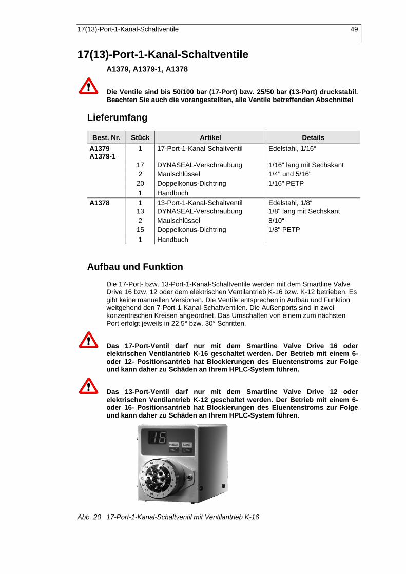
17(13)-Port-1-Kanal-Schaltventile 49
17(13)-Port-1-Kanal-Schaltventile A1379, A1379-1, A1378
Die Ventile sind bis 50/100 bar (17-Port) bzw. 25/50 bar (13-Port) druckstabil. Beachten Sie auch die vorangestellten, alle Ventile betreffenden Abschnitte!
Lieferumfang
Best. Nr. Stück Artikel Details A1379 A1379-1
1 17-Port-1-Kanal-Schaltventil Edelstahl, 1/16“
17 DYNASEAL-Verschraubung 1/16" lang mit Sechskant 2 Maulschlüssel 1/4" und 5/16" 20 Doppelkonus-Dichtring 1/16" PETP 1 Handbuch A1378 1 13-Port-1-Kanal-Schaltventil Edelstahl, 1/8“ 13 DYNASEAL-Verschraubung 1/8" lang mit Sechskant 2 Maulschlüssel 8/10“ 15 Doppelkonus-Dichtring 1/8" PETP 1 Handbuch
Aufbau und Funktion
Die 17-Port- bzw. 13-Port-1-Kanal-Schaltventile werden mit dem Smartline Valve Drive 16 bzw. 12 oder dem elektrischen Ventilantrieb K-16 bzw. K-12 betrieben. Es gibt keine manuellen Versionen. Die Ventile entsprechen in Aufbau und Funktion weitgehend den 7-Port-1-Kanal-Schaltventilen. Die Außenports sind in zwei konzentrischen Kreisen angeordnet. Das Umschalten von einem zum nächsten Port erfolgt jeweils in 22,5° bzw. 30° Schritten.
Das 17-Port-Ventil darf nur mit dem Smartline Valve Drive 16 oder elektrischen Ventilantrieb K-16 geschaltet werden. Der Betrieb mit einem 6-oder 12- Positionsantrieb hat Blockierungen des Eluentenstroms zur Folge und kann daher zu Schäden an Ihrem HPLC-System führen.
Das 13-Port-Ventil darf nur mit dem Smartline Valve Drive 12 oder elektrischen Ventilantrieb K-12 geschaltet werden. Der Betrieb mit einem 6-oder 16- Positionsantrieb hat Blockierungen des Eluentenstroms zur Folge und kann daher zu Schäden an Ihrem HPLC-System führen.
Abb. 20 17-Port-1-Kanal-Schaltventil mit Ventilantrieb K-16

50 Schaltbeispiele mit Mehrkanalventilen
Das Haupteinsatzgebiet dieser Multiportventile ist ihre Verwendung als Fraktionssammler. Sie bieten handelsüblichen Fraktionssammlern nicht nur den beachtlichen Preisvorteil, sondern auch funktionelle Vorteile. Wesentlich ist, dass Form und Größe der Sammelgefäße völlig frei wählbar sind. Weiterhin läßt sich beim Arbeiten mit der präparativen Version von EuroChrom® die Zahl der getrennt gesammelten Fraktionen durch Kombination von bis zu 8 Ventilen beliebig erweitern. Damit stehen bis zu 120 Sammelpositionen zur Verfügung.
Für präparative Anwendungen, das heißt mit größeren Flussraten, ist das 13-Portventil mit seinen 1/8“ Anschlüssen vorzuziehen. In diesem Fall stehen bis zu 88 Sammelpositionen zur Verfügung.
Grundsätzlich können mit den 17-Port- bzw. 13-Port-1-Kanal-Schaltventilen auch die anderen Funktionen der 7-Port-1-Kanal-Schaltventilen erfüllt werden. Für die Herstellung von Stufengradienten oder für sonstige Eluentenvariationen gilt das ohne Einschränkung.
Beim Aufbau von Säulenschaltungen gilt jedoch einschränkend, dass sie nur bis zu einer Druckbelastung von 25 bar (A1378), 50 bar (A1379) beziehungsweise 100 bar (A1379-1) betriebssicher sind. Die höhere Druckstabilität des Ventils A1379-1 wird durch eine veränderte Anordnung der Tellerfedern erzielt, vergleiche Abb. 21. Als Nachteil muß dabei allerdings ein erhöhter Verschleiß in Kauf genommen werden.
A1379 A1379-1
Abb. 21 Anordnung der Tellerfedern in 17-Port-1-Kanalventilen
Schaltbeispiele mit Mehrkanalventilen In diesem Abschnitt werden verschiedene Schaltbeispiele der Mehrkanalventile vorgestellt, ohne einen Anspruch auf Vollständigkeit erheben zu können. Durch geeignete Kombinationen lassen sich mit Sicherheit noch weit mehr spezielle Aufgaben der HPLC realisieren.
Säulenselektion mit einem 2-Kanalventil
Die Probe wird auf der Vorsäule vorgetrennt. Dabei kann ein Teil der vorgetrennten Probenkomponenten auf Säule 1 und nach Umschalten (gepunkteter/gestrichelter Weg) auf Säule 2 weiter getrennt werden.
Injektionsventil
Detektor
6
1
2
3
4
5
Vorsäule
Säule 2
Säule 1
Abb. 22 Säulenselektion mit einem Zweikanalventil

Schaltbeispiele mit Mehrkanalventilen 51
Probenvorreinigung durch eine Vorsäule
Die Probensubstanzen werden auf einer Vorsäule festgehalten. Nach der Säulenumschaltung (gepunkteter/gestrichelter Weg) werden Sie mit einem anderen Eluenten oder Gradienten in die analytische Trennsäule transportiert.
Injektionsventil
Detektor
6
1
2
3
4
5
Vorsäule
Trennsäule
Abb. 23 Probenvorreinigung mit Vorsäule und einem Zweikanalventil
Säulenselektion mit einem 3-Kanalventil
Es kann von Säule 1 auf Säule 2 (gepunkteter/gestrichelter Weg) umgeschaltet werden, ohne dass der Betrieb unterbrochen wird.
Injektionsventil
Detektor
6
1
2
3
4
5
Säule 2
Säule 1
Abb. 24 Säulenselektion mit einem Dreikanalventil
Vorsäulenrückspülung
Zunächst wird die Probe durch die Vorsäule geleitet, bevor sie in die analytische Trennsäule gelangt. Durch Umschalten (gepunkteter/gestrichelter Weg) werden die Säulen in umgekehrter Reihenfolge und Richtung gespült, so dass auf der Vorsäule zurückgehaltene Probenkomponenten eluiert werden.
InjektionsventilDetektor
6
1
2
3
4
5
Vorsäule
Trennsäule
Abb. 25 Vorsäulenrückspülung mit einem Dreikanalventil

52 Schaltbeispiele mit Mehrkanalventilen
Säulenrückspülung Nach beendeter Chromatogrammaufnahme wird durch Umschaltung (gepunkteter/gestrichelter Weg) die Säule in umgekehrter Richtung gespült. Stark retardierte Substanzen werden durch Rückspülung, gegebenenfalls mit einem anderen Eluenten, aus der Säule entfernt.
InjektionsventilDetektor
6
1
2
3
4
5
Trennsäule
Abb. 26 Säulenrückspülung mit einem Dreikanalventil
Probenanreicherung Die Analysensubstanzen werden in der Vorsäule angereichert (gepunkteter/gestrichelter Weg). Nach dem Umschalten des Ventils wird die Probe mit einem durch eine zweite Pumpe und gegebenenfalls anderen Eluenten in entgegengesetzter Richtung aus der Vorsäule gespült und in die analytische Trennsäule überführt.
Detektor Trennsäule
Vorsäule
Injektionsventil
6
1
2
3
4
5
Pumpe 1
Pumpe 2
Ablauf Abb. 27 Säulenrückspülung mit einem Dreikanalventil
Alternierende Anreicherung mit Vorsäulendurchspülung Über das Injektionsventil fördert die Pumpe 1 die Probe zur Anreicherung in die Vorsäule 1. Gleichzeitig wird die zuvor (vor dem letzten Umschalten) in der Vorsäule 2 angereicherte Probe durch den von Pumpe 2 geförderten Eluenten zur Analyse in die Trennsäule transportiert. Dieser Vorgang läuft mit jedem Umschalten alternierend ab.
Detektor 1
Injektionsventil6
1
2
3
4
5
6
1
2
3
4
5
Vorsäule 1
Vorsäule 2
Trennsäule
Detektor 2
Pumpe 1
Pumpe 2
Abb. 28 Alternierende Anreicherung und Vorsäulendurchspülung mit zwei Dreikanalventilen

Schaltbeispiele mit Mehrkanalventilen 53
Um ein Blockieren der Pumpen oder Fehlleitungen zu vermeiden, muss das Umschalten der Ventile immer zügig und vor allem völlig synchron erfolgen!
Ventile, in denen zwei benachbarte Ports durch eine Kapillarbrücke kurz geschlossen sind, können auch durch Zweikanalventile ersetzt werden.
Alternierende Anreicherung mit Vorsäulenrückspülung
Stark retardierende Probenkomponenten werden auf der Vorsäule angereichert. Nach Umschaltung werden diese Komponenten durch Vorsäulenrückspülung mit einem anderen Eluenten zur weiteren Auftrennung auf die Trennsäule geführt. Da zwei Vorsäulen angeschlossen sind, kann auf diesen alternierend und parallel zur weiteren Auftrennung angereichert werden ohne den Lauf zu unterbrechen. Der Eluentenstrom der Pumpe 2 ist zur leichteren Unterscheidung gestrichelt beziehungsweise punktiert (nach Umschaltung) dargestellt.
Detektor 1
Injektionsventil
6
1
2
3
4
5
6
1
2
3
4
5
Detektor 2
Pumpe 1
Pumpe 2Trennsäule
Vorsäule 1
Vorsäule 2
Abb. 29 Alternierende Anreicherung und Vorsäulenrückspülung mit zwei Dreikanalventilen
Um ein Blockieren der Pumpen oder Fehlleitungen zu vermeiden, muss das Umschalten der Ventile immer zügig und vor allem völlig synchron erfolgen!
Ventile, in denen zwei benachbarte Ports durch eine Kapillarbrücke kurz geschlossen sind, können auch durch Zweikanalventile ersetzt werden.
Alternierende Probenvorreinigung mit Vorsäulendurchspülung
Die Probe wird auf einer Vorsäule vorgereinigt. Die hier nur schwach retardierten Probenkomponenten werden auf die analytische Säule gespült und aufgetrennt. Nach Umschalten wird die Vorsäule mit einem anderen Eluenten durchspült um die stärker retardierten Komponenten zu entfernen. Der Vorgang verläuft über zwei Vorsäulen alternierend.
6
1
2
3
4
5
Detektor 2Abfall Injektionsventil6
1
2
3
4
5
Vorsäule 1
Vorsäule 2
Detektor 1
Pumpe 1
Pumpe 2Trennsäule
Abb. 30 Alternierende Probenvorreinigung und Vorsäulendurchspülung mit zwei Dreikanalventilen

54 Schaltbeispiele mit Mehrkanalventilen
Um ein Blockieren der Pumpen oder Fehlleitungen zu vermeiden, muss das Umschalten der Ventile immer zügig und vor allem völlig synchron erfolgen!
Ventile, in denen zwei benachbarte Ports durch eine Kapillarbrücke kurz geschlossen sind, können auch durch Zweikanalventile ersetzt werden.
Alternierende Probenvorreinigung mit Vorsäulenrückspülung
Die Probe wird auf einer Vorsäule vorgereinigt. Die hier nur schwach retardierten Probenkomponenten werden auf die analytische Säule gespült und aufgetrennt. Nach Umschalten werden die stark retardierten Komponenten aus der Vorsäule mit einem anderen Eluenten durch Rückspülung entfernt. Der Vorgang verläuft über zwei Vorsäulen alternierend.
Der Eluentenstrom der Pumpe 2 ist zur leichteren Unterscheidung gestrichelt beziehungsweise punktiert (nach Umschaltung) dargestellt.
6
1
2
3
4
5
Detektor 2Abfall
Injektionsventil6
1
2
3
4
5
Detektor 1
Pumpe 1Pumpe 2
Trennsäule
Vorsäule 2
Vorsäule 1
Abb. 31 Alternierende Probenvorreinigung und Vorsäulenrückspülung mit zwei Dreikanalventilen
Um ein Blockieren der Pumpen oder Fehlleitungen zu vermeiden, muss das Umschalten der Ventile immer zügig und vor allem völlig synchron erfolgen!
Ventile, in denen zwei benachbarte Ports durch eine Kapillarbrücke kurz geschlossen sind, können auch durch Zweikanalventilen ersetzt werden.

Reparatur- und Wartungshinweise 55
Reparatur- und Wartungshinweise SOP 8 Demontage der Ventilkörper
1. Lösen Sie gleichmäßig alternierend die drei Imbusmontageschrauben des Ventils.
2. Zerlegen Sie nun das Ventil in der Reihenfolge der Explosionsdarstellungen (Abb. 4 und Abb. 13 auf den Seiten 37 und 44).
3. Tauschen Sie defekte Teile (z.B. die Rotordichtung) aus. 4. Bauen Sie das Ventil in umgekehrter Reihenfolge wieder zusammen. Achten
Sie dabei auf die korrekte Reihenfolge und Orientierung (z. B. der Tellerfedern).
5. Die richtige Ausrichtung der Rotordichtung der verschiedenen Ventile entnehmen Sie den Darstellungen der nachfolgenden Tabelle.
Ventiltyp Einbaulage der Rotordichtungen
1-Kanal Körnung
Rotor mit DichtungRotor
Zylinderstifte
Einbauinjektions-ventil
2-Kanal
3-Kanal
Beim Zusammenschrauben des Ventils, wiederum gleichmäßig alternierend, zentriert sich die Rotordichtung automatisch und wird durch die Tellerfedern plan auf die Statordichtfläche gelegt, ohne dass eine Justage erforderlich ist.
Eine Schiefmontage der Rotordichtung ist durch das Ventildesign ausgeschlossen. Daraus resultiert eine lange Lebensdauer der Rotordichtung und des gesamten Ventils.
Rotordichtungen mit nur leichten Kratzern können Sie selbst wieder glätten: Legen Sie ein besonders feines Schleifpapier (z.B. 1000 oder Rouge) auf eine glatte Unterlage und reiben Sie die Rotordichtung mit gleichmäßig kreisenden Bewegungen über das Schleifpapier.

56 Reparatur- und Wartungshinweise
SOP 9 Einsetzen einer neuen Nadeldichtung in den Spritzenport
8. Entfernen Sie die alte Nadeldichtung. 9. Führen Sie die neue Nadeldichtung in die Verschraubung ein. 10. Versehen Sie die Nadeldichtung mit Zangenklemmring (der alte kann
üblicher Weise wieder verwendet werden und einem neuen Polymerdichtring. Alternativ können beide Teile durch einen Polymerdoppelkonusring ersetzt bwerden.
11. Ziehen Sie die Verschraubung leicht an. 12. Führen Sie eine Injektionsspritze in die Nadeldichtung ein. 13. Schieben Sie die Nadelführung mit der Spritze bis zum Anschlag in den
Spritzenport ein. 14. Ziehen Sie die Verschraubung moderat so stark an, dass sich die Spritze
noch leicht aber mit spürbarer Reibung herausnehmen läßt.
Nadeldichtung DYNASEAL-verschraubung Doppelkonusdichtung Nadeldichtung
Abb. 32 Spritzenport mit Nadeldichtung

Zubehör und Ersatzteile 57
Zubehör und Ersatzteile Ersatzteile
Artikel Ventil Bestellnr. 6-Portventile 1/16“ A0611 6-Portventile 1/8“ G2527 7-Portventile A0880
Rotordichtung
17(13)-Portventile P3058 Reed-Kontakt Alle G0365 Magnetkern Alle M0528
1/16“ Injektionsventile P0653 Nadeldichtung 1/8“ Injektionsventile P0955
Zubehör
Artikel Bestellnr. Handbuch V7447 Universalwinkel zur Ventilbefestigung A4018 Haltewinkel für K-120 A0406 Analytische Probenschleifen
1/16“, Edelstahl 5, 10, 20, 30, 50, 75, 100, 200, 500, 1000, 2000µl
1/16“ PEEK 10, 20, 50, 200, 500µl
Präparative Probenschleifen 1/8“, Edelstahl oder PEEK
1, 2, bis 11, bis 45ml 1/16“, Edelstahl oder PEEK
bis 11, bis 45ml
Injektionsspritzen 10, 25, 50, 100, 250, 500, 1000, 2500µl
A0723-A0730
58 Guarantee statement
Guarantee statement The guarantee period for the Switching and Injection Valves, Order No. A1357, A1358, A1359, A1360, A1361, A1362, A1363, A1364, A1365, A1366, A1367, A1368, A1369, A1369-1, A1370, A1371, A1371-1, A1372, A1373, A1374, A1375, A1376, A1377, A1378, A1379, A1379-1, and A1378 is 12 months beginning with the dispatchment date from Berlin. Operation inconsistent with manufacturer's instructions or damage caused by unauthorized service personnel are excluded from the guarantee. Damage caused by blockages and/or wear and tear of parts such as fuses and seals are not covered by the guarantee. Claims under this guarantee are only valid if the enclosed guarantee card has been returned to us at the address shown below within 14 days of receipt of the instrument. Defective valves should be sent to the manufacturer for repair.
Wissenschaftliche Gerätebau Dr. Ing. Herbert Knauer GmbH Hegauer Weg 38 D-14163 Berlin Germany Tel: +49 (0)30 – 809 727 – 0 Fax: +49 (0)30 – 801 50 10 E-mail: [email protected] www.knauer.net
If we find a defect covered by the guarantee, repair or replacement, at our discretion, will be carried out free of charge. Packing and transport costs are borne by the purchaser.
Garantiebedingungen Die werksseitige Garantie für die Schalt- und Injektionsventile mit den Bestellnummern A1357, A1358, A1359, A1360, A1361, A1362, A1363, A1364, A1365, A1366, A1367, A1368, A1369, A1369-1, A1370, A1371, A1371-1, A1372, A1373, A1374, A1375, A1376, A1377, A1378, A1379, A1379-1 und A1378 beträgt ein Jahr ab Versanddatum. Unsachgemäße Bedienung der Ventile und Folgen einer Fremdeinwirkung sind hiervon ausgenommen. Ebenso sind Verschleissteile und Verstopfungsschäden sowie Verpackungs- und Versandkosten von der Garantie ausgenommen. Die über die gesetzliche Gewährleistung hinausgehende Garantie wird nur dann gewährt, wenn die beiliegende Registrierkarte innerhalb von vierzehn Tagen an uns zurückgesandt wird. Bitte wenden Sie sich bei Fehlfunktionen Ihres Ventils direkt an das Herstellerwerk:
Wissenschaftliche Gerätebau Dr. Ing. Herbert Knauer GmbH Hegauer Weg 38 D-14163 Berlin Tel: 030 – 809 727 – 0 Fax: 030 – 801 50 10 e-Mail: [email protected] www.knauer.net
Die Verpackung unserer Geräte stellt einen bestmöglichen Schutz vor Transportschäden sicher. Prüfen Sie dennoch jede Sendung sofort auf erkennbare Transportschäden. Bitte wenden Sie sich im Falle einer unvollständigen oder beschädigten Sendung innerhalb von drei Werktagen an das Herstellerwerk. Bitte unterrichten Sie auch den Spediteur von etwaigen Transportschäden.
Wenn wir nach Durchführung der notwendigen Kontrollprozesse einen Mangel oder Defekt feststellen, der unter die Garantie fällt, wird kostenfrei nach unserer Entscheidung eine Reparatur oder ein Austausch vorgenommen. Verpackungs- und Versandkosten trägt der Käufer.

Declaration of conformity 59
Declaration of conformity
Konformitätserklärung Manufacturer’s name and address: Herstellername und -adresse
Wissenschaftliche Gerätebau Dr. Ing. Herbert KNAUER GmbH Hegauer Weg 38 14163 Berlin, Germany Switching and Injection Valves, Schalt- und Injektionsventile,
Order Number, Bestellnummer: A1357, A1358, A1359, A1360, A1361, A1362, A1363, A1364, A1365, A1366, A1367, A1368, A1369, A1369-1, A1370, A1371, A1372, A1373, A1374, A1375, A1376, A1377, A1378, A1379, A1379-1 und A1378 comply with the following requirements and product specifications:
● Low Voltage Ordinance (73/23/EWG) EN 61010-1 (08/2002)
● Engineering Guidelines (89/392/EWG) ● EMC Ordinance (89/336/EWG)
EN 6100-3-2 (10/2006) EN 61326-1 (10/2006)
entsprechen den folgenden Anforderungen und Produktspezifikationen:
● Niederspannungverordnung (73/23/EWG) EN 61010-1 (08/2002)
● Maschinenrichtlinie (89/392/EWG) ● EMV-Verordnung (89/336/EWG)
EN 6100-3-2 (10/2006) EN 61326-1 (10/2006)
The product was tested in a typical configuration. Das Produkt wurde in einer typischen Konfiguration geprüft. Berlin October 11, 2007
Alexander Bünz (Managing Director)

60 Konformitätserklärung
Using this Manual ................................................................................................ 5
SOPs in this manual..................................................................................... 5 General ................................................................................................................ 7 Capillary Connections .......................................................................................... 7 Manually driven 6-Port-3-Channel Valves ........................................................... 9
Delivery Content........................................................................................... 9 Layout and Function................................................................................... 10 Installation .................................................................................................. 11 Operation.................................................................................................... 12
Using the valve as a Switching Valve ................................................................ 12 Electrically driven 6-Port-Multi-Channel Valves................................................. 13
Delivery Content......................................................................................... 13 Layout and Function................................................................................... 14
Use as an Injection Valve .................................................................................. 15 Using the valve as a Switching Valve ................................................................ 15 Special version for the 6-Port-2-Channel Valve................................................. 15 Manual 6-Port-2-Channel Injection Valve .......................................................... 16
Delivery Content......................................................................................... 16 Assembly and Function.............................................................................. 16
Manual 6-Port-3-Channel Switching Valves ...................................................... 18 Delivery Content......................................................................................... 18 Layout and Function................................................................................... 19
7-Port-1-Channel Valves.................................................................................... 19 Delivery Content......................................................................................... 19 Layout and Function................................................................................... 20 Examples for using the 7-Port-1-Channel Switching Valves...................... 20
Step-function gradient........................................................................................ 20 Fraction collector................................................................................................ 21 Column switching............................................................................................... 21 17(13)-Port-1-Channel Switching Valves........................................................... 22
Delivery content.......................................................................................... 22 Layout and Function................................................................................... 22
Examples for switching with Multiport Valves .................................................... 23 Column selection with a 2-Channel Valve ................................................. 23 Using a precolumn to precondition the sample.......................................... 24 Selecting a column with a 3-Channel Valve............................................... 24 Precolumn back-flushing............................................................................ 24 Column back-flushing................................................................................. 25 Sample enrichment .................................................................................... 25 Alternating enrichment with a precolumn through rinsing.......................... 26 Alternating enrichment with precolumn back-flushing................................ 26 Alternating sample preconditioning with precolumn through rinsing ............. 27 Alternating sample preconditioning with precolumn back-flushing ............ 27
Repair and Service Note.................................................................................... 28 Accessories and Spare Parts............................................................................. 30 Spare Parts ........................................................................................................ 30 Accessories........................................................................................................ 30 Zur Benutzung des Handbuches ....................................................................... 31
Standardarbeitsanweisungen in diesem Handbuch................................... 31 Allgemeines........................................................................................................ 33 Kapillar-Verbindungen ....................................................................................... 34 Manuell betriebene 6-Port-3-Kanal-Ventile........................................................ 35
Lieferumfang .............................................................................................. 35 Aufbau und Funktion .................................................................................. 36 Installation .................................................................................................. 38 Inbetriebnahme und Bedienung ................................................................. 38
Verwendung als Injektionsventil......................................................................... 38 Verwendung als Schaltventil.............................................................................. 39 Elektrisch betriebene 6-Port-3-Kanal-Ventile..................................................... 40
Lieferumfang .............................................................................................. 40 Aufbau und Funktion .................................................................................. 41

Konformitätserklärung 61
Verwendung als Injektionsventil .........................................................................42 Verwendung als Schaltventil ..............................................................................42 Sonderausführung als 6-Port-2-Kanalventil .......................................................42 Manuelle 6-Port-2-Kanal-Einbauinjektionsventile...............................................43
Lieferumfang ...............................................................................................43 Aufbau und Funktion...................................................................................43
Manuelle 6-Port-3-Kanal-Einbauschaltventile ....................................................45 Lieferumfang ...............................................................................................45 Aufbau und Funktion...................................................................................46
7-Port-1-Kanal-Schaltventile...............................................................................46 Lieferumfang ...............................................................................................46 Aufbau und Funktion...................................................................................47 Einsatzbeispiele der 7-Port-1-Kanal-Schaltventile .....................................48
Stufengradient ....................................................................................................48 Fraktionssammler ...............................................................................................48 Säulenschaltung .................................................................................................48 17(13)-Port-1-Kanal-Schaltventile ......................................................................49
Lieferumfang ...............................................................................................49 Aufbau und Funktion...................................................................................49
Schaltbeispiele mit Mehrkanalventilen ...............................................................50 Säulenselektion mit einem 2-Kanalventil ....................................................50 Probenvorreinigung durch eine Vorsäule ...................................................51 Säulenselektion mit einem 3-Kanalventil ....................................................51 Vorsäulenrückspülung ................................................................................51 Säulenrückspülung .....................................................................................52 Probenanreicherung ...................................................................................52 Alternierende Anreicherung mit Vorsäulendurchspülung ...........................52 Alternierende Anreicherung mit Vorsäulenrückspülung .............................53 Alternierende Probenvorreinigung mit Vorsäulendurchspülung .....................53 Alternierende Probenvorreinigung mit Vorsäulenrückspülung ...................54
Reparatur- und Wartungshinweise.....................................................................55 Zubehör und Ersatzteile .....................................................................................57 Ersatzteile ...........................................................................................................57 Zubehör ..............................................................................................................57 Guarantee statement..........................................................................................58 Garantiebedingungen .........................................................................................58 Declaration of conformity....................................................................................59 Konformitätserklärung ........................................................................................59