inlentor - americanradiohistory.com circuits for this reason. the specifications are quite good and...
TRANSCRIPT

'up-to-date electronics for lab and leisurbL.
InLeNTor

194 - elektor january 1077
Elall141111" uemmer
Editor W. van der Horst
Deputy editor P. Holmes
Technical editors J. BarendrechtG.H.K. DamE. KrempelsauerG.H. NachbarFr. ScheelK.S.M. Walraven
Art editor C. Sinke
Subscriptions : Mrs. A. van Meyel
UK editorial offices, administration a. advertising:6 Stour Street, Canterbury, CT1 2XZ.Tel. Canterbury 102271. 54430. Telex: 965504.Bank: Midland Bank Ltd Canterbury A/C no. 11014587,Sorting code 40.16-11, giro no. 3154254
Assistant Manager and Advertising : R.G. KnappEditorial T. Einmens
Elektor is published monthly on the third friday of each month,price pence.Please45 note that number 27/28 (Jul /Au is a double issue,'Summer Circuits', price 90 pence.Single copies )including back issues) are mailable by past room ourCanterbury office to UK addresses and to all usurer. by surface mailat £ 0.60Single copies by air mail to all countries are £ 0.95Subscriptions for 1977 (January to December inclusive): to UK ad-dresses and to all countries by surface mail: £ 6.25, to all countries byair mail E 11.-.All prices include pa, p.
Change of address. Please allow at least six weeks for change of address.Include your old address, enclosing, if possible, an address label from a
, recent issue.
Letters Mould be addressed to the department concerned:TO = Technical Queries, ADV - Advertisements, SUB = Subscriptions:ADM = Administration; ED - Editorial (articles submitted forpublication etc.); EPS = Elektor printed circuit board service.For technical queries, please enclose a stamped, addressed envelope.
The circuits published are for domestic use only. The submission ofdesigns or articles to Elektor implies permission to the publishers toalter and translate the text and design, and to use the contents in otherElektor publications and activities. The publishers cannot guarantee toreturn any material submitted to them. All drawing. photographs,printed circuit boards and articles published in Elektor are copyrightand may not be reproduced or imitated in whole or part without priorwritten permission of the publishers.
Patent protection may exist in respect of circuits, devices, componentsetc. described in this magazine.The publishers do not accept responsibility for faredlltewe..fy suchpatent or other protection.
National advertising rates for the English edition of Elektor and/orinternational advertising rates for advertising at the same time MtheEnglish, Dutch and German issues are available on request.
Distribution: Spotlight Magazine Distributors Ltd,Spotlight House 1, Benssvoll Road, Holloway, London 197 7AX.
Copyright C)1977 Elektor publishers Ltd - Canterbury.
Printed in the Netherlands.
What is a TUN?Whet is 10 n?What is the EPS service,What is the TQ service?What is a missing link?
Semiconductor typesVery often, a large number ofeuivalent semico.uctors exist
ith different type numbers. Fmthis reason 'abbreviat.' typenumbers are used in Elektorwherever possible:- '791' stands for p4741,
LM 741, MC741,
- 547271M,Ie0tc7.4,
RM741, I1,'TUP' or (Transistor,Universal, PNP or NPN respectively) mends for any lowfrequency silicon transistorthat meets Me specificationslisted in Table 1. Someexamples are listed below.
- 'DUS' or 'DUG' (Diode, Uni-var.!, Silicon or Germaniumrespectively) stands for anydiode that meets the specifi-cations listed in Table 2.
- '00107E1%1302376',11105479 all refer to the same'family' of almost identicalbetterssuality silicon transistors. In general, any othermember of the same familycan be used instead. (Seebelow.)
For further information, seeTUP', TUN, DUG, DU5',Elektor 20, p. 1234.
Table 1. Minimum specificationsfor TUP IPNPI a. TUN (NMI.
-VCEO, maxIC, maxIffe rein
7, mitm n
20V100 mA100100 mW100 MHz
borne ]UN's are: BC107, BC108std BC109 families; 2438564,
243859, 2N3860, 243909,243947, 244124. Some 'OUP'sre: 60177 and 60178 families;
00179 family with the possiblexeption of BC159 and 130179;
2N2412, 243251, 2N3906,244126, 244291.
Table 2. Minimum specificationsfor DUS (silicon) and DUG(germanium).
DOS DUGVH, maxIF, max431, max
t13%aXx
25V1003A1PA250mW5pF
20035mA100µA250mW10pF
Some .005.1 re: BA127, 04217,BA218, BA221, 04222, 04317,BA318, BAX13, BAY61, 119914,144148.Some '1:W0's are: 0A85, 0491,0A95, 44116.
10107 bill. -91 families:BC107 (-8, -91, 80147 1-8, .91,BC207 143, .91, 00237 (43, .91.13031760547
16..91,(-8, .91,
003476C171
18. -9),1-2, -31,
BC18200437
41,(-8, -91,
5038280414
13, A),
O 017716, 91 families:B C177 (6, -91, 00157 I-8. -91,80204 (-5, -61,130307 (8, 91,BC320 (-1, -21, 90350 1-1, -2),BC557 16, -91, 80251 (9,91,00212 19, 41, BC512 (-3, -41,BC261 1-2, -31, BC416.
Resistor and capacitor valuesWhen giving component values,decimal points and large numbersof zeros are avoided whereverpossible. The decimal point isusually replaced by one of Me fol-lowing international abbrevi-ations:P (Pico7 - 103F
Ina o-1 =10'Imicro) =10'
rn (milli-) = 1033k (kilo-) = 103M (mega-) = 103G (gigs-) = 103A few examples:Resistance value 2k7: this is2.7101, or 2700 0.Resistance value 470: this is470 D.Capacitance value 4p7: this is4.7 pF, or0.000 000 000 004 7 FCapacitance value 10 n: this is theinternational way of writing10,000 pF or .01 pF, since 1 n is10' farads or 1000 pp.
Mains voltages190 mains (power line) voltagesare listed in Elektor circuits. It isassumed that our readers knowwhat voltage is standard in theirpart o the world)Readefrs in countries that use60 Ha should note that Elektorcircuits are designed for 50 Hzoperation. This will not normallybe a problem: howessr, in easeswhere the mains frequency 4 usedfor synchronisation wine mortifi-cation may be required.
Technical services no readers- EPS service. Many Elektor
articles include a lay -out for aprinted circuit board.Some - but not all - of thewboards are availablere.ywchert a. predrill..The 'EPS print service list' inMe current issue always gives acomplete list of availableboards.
- Technical queries.Members of the technical staffare available to answer tech-
ical queries (relating toarticles published in Elektor)by telephone on Mondaysfrom 14.00 to 16.30.Letters with technical queriesshould be address. to:Dept. TQ. Please enclose astamped, self address. envel-ope ; readers outside U.K.please enclose an I RC insteadof stamps.
- Missing link. Any importantmodifications to, additions to,improvements on or correc-
ns in Elektor circuits aregioenerally listed under theheading 'Missing Li.3 at Meearliest opportunity.

---contents elektor jams, 1977 -741
CORTEHTS Volume 3Number 1
Despite its simple designthe stereo audio mixerwill accept inputs frommicrophone, magneticcartridge, or 'flat' linesources.
The noise generatordescribed in this issueuses digital techniques toproduce a pseudo -randombinary noise signal.Suitable filtering convertsthis to analog 'white' or'pink' noise.
This photo of a Y-preampillustrates the modularconstruction of theElektorscope.
Not a microphotographof snow crystals, butneatly packed heat -sinks!
selektor 110
elektoracle 113
stereo audio mixer 114This is a design fora simple but high -quality, portable, f We -input, stereo mixer intended for um in discos or for taperecording.
marbles 120Playing marbles is rtill one of the mart universal of childhoodpleasures. In this modern day end age, it was only a questionof time before some designer tried his hand at designing anelectronic equivalent...
noise generator 123A digital method of generating so-called pseudovandom'white' and 'pink' noise is described in this article and appliedin a practical circuit.
audio wattmeter - J. Jacobs 128
elektorscope (2) 130A linear timebase and stable trigger' circuits are essential tothe operation of an oscilloscope.In this month's article the circuit of the tirnebase, triggercircuit, X and Y amplifiers, channel switches and Y-preampsare discussed.
quadi-complimentary complemented 139
bi-fet opamps 140Interesting results can often he obtained by using severaldifferent types of active device in one t. A relativelynew example of this is the 81.FET opamp.circui It consists ofJFETs end bipolar transistors on the same chip, and thiscould well give interesting results at a reasonable price.
is audio 142In this article two completely different types of high -poweraudio ICs are discussed. To avoid confusion the article is splitinto two parts. The feat part deals with hybrid power -integrated circuits while the second section deals with theTDA 2020 IC.
the BF 494 -a case in point 148
transistors 149
market 150
linear iris, mos ics, ttl ics 157
tap-tun-dug-dus 160

1
elektor January 1922 - 1-09
dekkoback ire,availableThis is a selection fromvarious issues:
number 1: @ 50 p- t.p.tun-d.g-ays
rnos clock- distortion meter- sensor- electronic loudspeaker- steam whistle
number 2: @ 50 pminidrurnuniversal displaydil led probetv sou.big benmodulation systemshow to gyrate
umber 3: @, 50 ptap prearmspll systemslidotime machinecompressordisc preampaid converterled displays
umber 4: @ 50 ptup-tun testerinterference suppressionin carsthief suppression @C."supplies for carsCybernetic beetlethe mothqua.° in practice
umber 5: @ 85 p'Summer Circuits' issue, withover 100 circuits: amplifiers,beneretors,dividers, universalfrequency reference, im-proved 2 -segment display,receivers, power supplies,rhythm generators,measuringequipment, etc.
number 6: @ 50 p- edwin amplifier
versitale digital clock- phasing- disco lights- ota- dual slope dvm- car clock
numbers 7 and 8:sold out
number 9: @ 55 pfeedback pll for fmfunction generatorracing car controlsimple mw receiverdigital master oscillatorpeic stereo decoder
umber 10: @ 55 pcall sign generatormorse decoderspeech processormorse typeNniterdigital wrist watch
um; ate otill
the contents of the
number 11: @ 55 ptv tennis extensions
- ssb receiver- tv an front end
adapter- dynamic noise limiter
integre. voltageregulators
number 12: @ 55 pre°rhythm generator
- polaroid timer- led meters
stylus balance
number 13: @ 55 pintegrated indoor fmaerialequin 12/
- digidisplaY- versatile logic probe
number 14: @ 55 pa.m. mains intercom
- fet probevhf I m reception
- led light show- digibell
number 15/16: @ 95 p'Summer circuits' issue,with over 100 circuits
number 17: @ 55 p- m.p.g. indicator- ignition timing strobe- car service meter- windscreen wiper delay- rev counter
number 18: @ 55 p- time on tv- score on tv
loud mouth- SO decoder
number 19: @ 55 p- other
metal detector- ceendar- intercom- signal horn- pulse generator
number 20: @ 55 p- thermometer
snooze -alarm -recto -clockParking meter alarm
- elektor index 1926- phasing and vibrato- elektorscolse- sirens
Prices quoted @ U.K./Surface rate.Airmail add. 35p
Following the success of the many original andvaried construction projects in Elektor
magazine we are now publishingBOOK 75.
Written and presented inElektor's uniquestyle its contents
include:
versatile digital clockmini hifitv tennis gametunable aerial amplifierdisc preampuniversal frequency referencetime signal simulatoredwin amplifier, fido and
i many te others
PLUS 'DATA SECTION' covering Elektorservice to readers, LED DISPLAY
MOS-ICS, TTL-ICS, OPAMPS,TRANSISTORS
andTUP-TUN-DUS-DUG.
For ordering please use the postage paid order cardin this issue.
stereo audio mixer1
AUDI
This is a design for a simple but high -quality,portable, five -input, stereo mixer intended foruse in discos or for tape recording. Despite itssimple design the mixer will accept inputs frommicrophone, magnetic cartridge, or 'flat' lineinputs.The total current consumption is quite low, sothe unit may be powered from batteries as wellas its own, integral, mains power supply.
In the fields of application for whichthis mixer is intended it was felt thatthe cost, complexity and weight of suchfacilities as tone and balance controlswere not justified. Such facilities arebest left to the professional studio
AtA block diagram of one channel of themixer is shown in figure 1. This is ofcourse duplicated for the other channel.It can be seen that the first three inputsare each provided with a preamplifier,
and any or all of these preamplifiers canbe constructed as either a disc or micro-phone preamp. The outputs of thepreamplifiers feed into faders (gaincontrols). The two remaining inputs areintended to be fed from 'flat' sourcessuch as tape, and these inputs are feddirect into the faders.The outputs from all the faders aremixed (more properly 'summed') at thevirtual earth input of the post ampifier,and the mixed output can then be fed
Specification
Inputs. Five (stereo) inputs,three microphone ormagnetic cartridge, plustwo line inputs.
Preamplifiergain. Disc inputs x 80138 dB)
Mir. inputs x225 (47 dB)Post amplifiergain. s1.25Maximum inputlevel lone inputdriven). Disc 44 rnV FIMS Sine -
wave into 47 k.Mic. 14 mV RMS Sine.wave into 47 k.Line 2.5 V HMS into47 k.
Maximum outputlevel 3.2 V RMS sinewase
from 600 11Frequencyresponse Line and Mic.: 20 Hz
kHz I-2dB).Disc -131,4 equalisationcorrect to 0- 1.5 dB.
Total harmonicdistortion Less than 0.1)11
Signal tonoise ratio Better than 70 dB.
o the tip, recorder, disco amplifier orwhatever. The post amplifier, accordingto the whim of the individual construe -or, may or may not be equipped with amaster gain control.
PreamplifiersFigure 2 is the complete circuit of onechannel of the stereo miner. The inputpreamplifier is constructed around T1
d T2, and is, of course, duplicated forinputs 2 and 3, though this is not shownin full. TI functions as a voltage ampli-fier with a relatively high gain, and thenoise figure is good due to the lowcollector current of approximately86 µA.T2 also operates as a voltage amplifier,but since the output signal is taken fromits collector, the collector resistor mustbe fairly low to obtain a reasonably lowoutput impedance that will not beunduly loaded by the fader PI.Negative feedback is provided from thecollector of T2 to the emitter of TI viaan equalisation network connected be-tween points X and Y.The networks for disc and microphoneinputs are shown at the bottom offigure 2. Note that for the disc preampR3 is 470 II, and for the microphone in-put, 1k5.The two line inputs require little com-ment, since they simply feed direct intothe faders P4 and PS. It is, of course,perfectly possible to convert any or allof the preamp inputs to line inputssimply by omitting the preamp com-ponents and joining points A and B.

dereo audio mixer elektor jenuery 1977 - 1-15
fegure 1. Block diagram of one channel of In,stereo mixer.
figure 2. Crunplete circuit of one channel ofthe stereo mixer.

Fr.
1-16 - Weldor tent., 1977
Photos 1 and 2. Showing how the potentio-meters may be mounted direct on the back oft he p.c. board.
stereo audio mixer

elektor jemmy 1977 - 1-1- 7
5
4r1-!-5 R_V1.0 0-11-0, ClAlt,n -I 444.0 1-15 _p_. iS?.'; 301nme lar Pisa's° 1.0 '-'T 1:r19: 01 t0
-y-4,74 0- 0.1w0 1.0 iu'AO 0-41 r17-0.. II 0 ,i,.. 1,,,,,, 0 0 5
---0 0.07 10,- 0 0 0HP4 1.0 0.10e. k:, 0 0.
°A-6-F" °ill) -A 3- ° - °{=i°q o ,f.,fo vine' .,.., 4) 01-0 0_001.__,
2, FOo''
41-1140 oil -no 0-11-01 ,tic:) -9,0_11_0),o0,o f; .11.04.,0 to ,es 1 g
wo-1 5' -o 0.10. fc-6.0_,F0 00 ,-70 r11.7 --o
- CH... 1001.. to 2 ' :1..1 o o 0.0... 10 04.: to o a. r,
w- 0.1... 1.0 °loose it0 4.O, 4,0-11-0 o__{0-.0-6).-11-0 0-11? 0-94'8' ,-,.0.. - L 010.' 10
d.041,111:k011,110.Hi ...(y -6-71.1."-.%
ing.11-0 Oil? C011-02 j ic!_ .2 OAF* ).0')Li .2, 011,8 If CHRIS 145 , 9.
0-111-0 01.. i° "," TO-IFO-6 k o ot,, to oin, ,, o ow w
0----.0 04.. 1.0-1 0 0{.... joailie. 10 0 Cli
0 q Dino, 10 04in re' i.0 41,3j. 9_04J-0 °---UFO _0-6- gf -I FO 0-117? 0114g ',vs. '2- k *71"
t0.11.1.1-ceolpmal-ci :1,0_, -5 0-InFO k0,-,
-.. 1-- 0'.fri- 011-4 F.
0-1E-0 V)8 101L., .1-1310 ,g0 -s 0-1.1, t:1 0/.17 }C. -n
'1 .co-177-1.1:- o cit414,}40 ',7-.1c./ 001610 0G1"00° 01,. h o 0. c,
1 O.
FOG9_
olo,10 04.,3 to "6-
Q---.3 0-1 1-0 -,r01.1700-1,9 w .0,' i-;
oiR.,}02.,1 .-; >n
211 eines 143 c
01....1.0oiwtorafo
o 0-01-0 o o of 11-0
o o o cops0-0 2204F-0 0
ai0-11-0
en 0 01 wee fow
Ogre,
0 I*1011,1
Parts list
Resistors:
Al = 47kR2 -120k63 = 470 0 DISC
I k5 MICR4.P16,R25= 3k3R5=470 nR7... 011,417.100k012 - 82 k913 = 15kR14=5600915 = 58 nR16 = 47 S2918.019= see text421,922.1824 = 10 n023= 1 k8726= 4k7927 = 820 0
Capacitors:C1,04 - 680 nC2,C7,C6= 47 p/15 VC3= 470 ai/3 VCS- 620 nCB= 220C9,C10,011 - abedC13,C14 = 47 nC15= 470 p/40 VC16 - 10 p/10 VC17=1006
Semiconductors:
T1 ,T3 = BC 549 CT2,T4 - BC 517 (Darlington)DI ... 04 = 4 x 144001 orbridge rectifier B40 0 400
D5= LEDICI =723 DI L
Miscellaneous:
Tr - 15 - 18 V/50 mA(minimum) transform,
31 = 50 mA fusePI ... P5 = 47 k log. stereo -
slider potentiometer
figure 4. Printed circuit beard far Me mixerand power supply MPS 94441.
figure 5. Component layout for figure 0.

r1-18 - elektor january 1977 stereo audio mixer
The outputs of the faders are connectedo the input of the post amplifier via
mixing resistors R7 to R11. To avoidany unwanted interaction between thenput signals the an. voltage at themixing mode must be zero. This is basi-cally what is meant by the term 'virtualearth': although the amplifier input isnot actually grounded its input Voltageis always very small. In other words theamplifier has a very low input im-pedance.This result is achieved by applying alarge degree of negative feedback fromthe emitter of T4 to the base of T3.When one of the input signals swingspositive this will attempt to force mombase current into T3. The collector ofT3, and hence the emitter of T4, willswing negative until the current throughR13 is the same as that through the in-put resistor (neglecting T3 basecurrent), and the a.c. voltage at theinput node will remain zero.The overall gain of the post amplifier isthe product of the gain of T3 (withfeedback) and the gain of T4. This is
given by
RI3 R14Rip x R15
i.e. about 1.25; Rinis one of the resi-stors R7 ... RI 1 .
The output of the post amplifier istaken from the collector of T4, the out-put impedance being 600 52. If desiredR17 may be replaced by a master fadercontrol, though in many cases this willnot be necessary as the succeedingequipment will have gain controls.
Power SupplyThe power supply is based on a 723 ICregulator, with its output set to 12 V,and this is more than adequate tosupply the small current taken by themixer without the need for heatsinks orextemal transistors. Due to tolerances inthe 723's internal reference voltage theoutput voltage may not be precisely

stereo audio mixer elektor January - 1.13
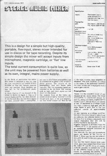
Photo 3. The completed mixer in its caw withthe lid removed.
figure 3. Power supply for the stereo mixer.
figure a. Frequency response of the mixer FIthe dec (fad via reciprocal RIAA network)microphone and line inputs.
12 V, but this is no cause for concern.
ConstructionA printed circuit board and componentlayout for the m are given infigures 4 and 5. It will bebe seen that theinput preamplers are duplicated inthree pairs, each numbered identically,the right channel components beingidentified by an apostrophe. Whenordering components it must be remem-bered that for the input preamps 6 offare required of each component, and forthe post amplifier, 2 off.For the faders, slider pots of theRS Components, Doram or Radioluntype should be used, as these may bemounted direct on the back of the p.c.board as shown in photos 1 and 2. Itshould be noted that the sliders for theline inputs are mounted on the back ofthe board adjacent to the power supply,on either side of IC1. Provision is madefor mounting the mains transformer onthe p.c. board, and this should provesatisfactory. However, if hum on theinputs is a problem it may be necessaryto mount the transformer remote fromthe board.Input and output wiring shouldconform to normal audio practice, carebeing taken to avoid earth loops.
Performance and ApplicationsFigures 6a, b, and c show respectivelythe frequency response of the disc,microphone and line inputs. It wouldhave been extremely easy to haveextended the h.f. response into theMHz region, but bearing in mind theprobable applications it was felt thatthis was simply inviting problems due toradio breakthrough and instability,especially in such applications as discosand tape recording where the layout ofleads may be somewhat haphazard. Forthis reason the response is confinedstrictly to the audio spectrum by theinclusion of C6, and C12 in the micro-phone preamp.The mixer may be used with most typesof magnetic cartridge and dynamicmicrophone, as well as with high-levelsources such as cassette decks, tapedecks and tuners. With high outputcartridges it may be found that over-loading of the preamp occurs, and theewe for this is simply attenuation of thecartridge output so that the preampreaches maximum output only onpeaks.

1-20 - swim, Onus, 1977
ARE 5
Playing marbles is still one of the most universalof childhood pleasures. In this modern day andage, it was only a question of time before somedesigner tried his hand at designing an electronicequivalent ...
There are any number of differengames that can be played with marbles.This electronic version simulates oneparticular variant: the object is to rollthe marble towards a wall, and theperson whose marble ends up closest tothe wall is the winner. It doesn't matterwhether it bounces off the wall first -the only thing that counts is the finalposition.In the electronic version, the romarble is simulated by an up/downcounter driving a column of LEDs(figure I). It is 'rolled' by pressing thestart button; the length of time thebutton is depressed corresponds to theinitial speed and this is where some skillis called for. Initially, LED 1 is on. Assoon as the button is pushed this LEDgoes out and LED 2 lights up; then this,in turn, goes out and LED 3 lights andso on. The speed with which the pointof light moves up the column dependson how long the start button is helddown.Since real marbles don't keep rolling atthe same speed all the way, some'friction' has been built in: the pointof light slows down gradually until itfinally comes to a standstill. One LEDis now on, corresponding to the finalposition of the marble. The three LEDsacross the top of the column are thewall' against which the 'marble'bounces, so the object of the exerciseis to end up with LED 16 lit up.Pushing the reset button resets thecounter, so that LED 1 is lit up readyfor the next try.
The circuitThe basic operation of the circuitis as follows. When the start button isdepressed an oscillator is started. Theinitial frequency depends on how longthe button is held down, and after it is
released the frequency of the oscillatorgradually decreases until it finally stops.The output from the oscillator drivesthe up/down counter (see figure 1). Thefour -bit output from this counter is
passed to a decoder which drives theLEDs.The complete circuit is shown in fig -re 2a and 2b. T1 and T2 are the oscil-
lator - in this ca a fairly standardmultivibrator circuit.se The frequency is

marbles alektor jammer 1977 - 1-21
4C3wve rwiawrwnFn a C
AD -
124 11112 r
0 0 0 8
NI N4 = ICI =7400
149 .. N12 = IC3=7400.. N22. ICI= 7413
N23... N24= ICS= 7413ic0 v 70193
2b a a,v
oir 10..0:: D. 011111141103 Fmg 411 :
lira%: D 44111111111113 E'm Cl :
: D.9
110C41 km . CI53:miN13... N13.104-2400
9, 25
N17... N20.1.-2400M.., -TOP01...010 -LEO red012.019 LE. green
Figure 1. Block diagram of 'electronicmarbles', showing the layout of the LEDs.
Figura 2. The complete circuit diagram. Fin-n in n the oscillator and counter with
msociated logic; figure lb is the decoder/driver.
determined by the setting of currentsource T3, or, to be more precise, onthe base voltage of this transistor. Whenthe start button M depressed C3 chargesup. The higher the voltage across C3,the higher the frequency of the oscil-lator - and the longer it will take for
the capacitor to discharge.The rate of charge of C3 can be presetwith P2, so this sets the ratio betweenthe initial speed and the length of timethe button is held down. The dischargetime depends on the setting of P I - the'friction' adjustment. P3 is the actual

1.22 - gleam isnussy 1977 marbles
'marble speed' control.The output et the collector of T2 is nota particularly good square -wave, so it is'polished up' by two Schmitt -triggers(N22 and N2I) in cascade.The up/down counter (IC8) has twoinputs, one for 'count up' and one for'count down'. Which of these inputs isdriven by the oscillator depends on thestate of the RS-flip/flop N3/N4.When the output of N3 is at logic 'I',N7 is freed and the counter counts up;when the output of N4 is 'high', thecounter counts down.When the reset button is depressed, theflip/flop is reset to the condition wherethe output of N3 is 'I'. The counter willnow count up until it reaches themaximum count (1111). At this pointthe output of N23 changes from 'I' to'0'. This low-level input to N4 sets theflip/flop. The output of N4 is now 'high'and the counter counts down. When itreaches the lowest count (0000) theoutput of N24 goes low', resetting theflip/flop again so that the counter startsto wont up again. The result of all thisis that the counter counts up and downcontinuously until the oscillator stops.The '4 - to - 16 decoder' and the LEDdrivers are shown in figure 2b. Thenumber of components required hasbeen reduced by incorporating twotricks: the LED drivers are part of thedecoder, and the decoder actuallyconsists of two .2 - to - 4' decodersinstead of one '4 - to - 16' type. For aparticular LED to light up, the left-handtransistor connected to its anode andthe right-hand transistor connected toits cathode must both be conducting.The left-hand transistors are driven bythe A and B outputs of the counter, asdecoded by N13 through N16, and theright-hand transistors are driven by theC and D outputs through a similardecoder (N17 through N20).The transistors are connected to theLEDs in such a way that the final resultis the desired '4 - to - 16' decode. Togive one example, if the counter outputis '1100' (A = 0, B 0, C I and D I)corresponding to a count of 12, thethirteenth LED should light up -remember that '0000' corresponds toLED I! In this case the output of NI3will be low, fuming on T4. At the sametime the output of N20 will also be low,turning on T11. T4 is connected to DI,DS, D9 and DI3, whereas TI1 drivesDI3, D14, DIS and DI6. The only LEDconnected to both transistors is DI3, soit lights up, as intended.LEDs DI7, D18 and D19 are the 'wall'.
0 0
031:111 it.
.5046 170, -9-9-/ , 9._,9 ,,, hL.0140 a a
0,446 -VC146
09045 '-'5'...1.4. 400 E E
u '
-2...1.0----0 '-6- -50.__ 0 O
o,,o146 .,-
''o c . a*
-9- 2 el [10 II IIIIIN
: 72 I ' 1 a 0
.,44.110 Tv a t
014410 T11 0- 9-0 4'0°
10cL:1.-,-p
s-lf'''' r-00 o+P
RellinOMR1.R2,R3,R5= 1 kR4= 10kR6 ... R13 = 2k2R14 = 100 n1315,11115 -18011m,p2= 470 k presetP3 = 2k5 pram
051PBCitOrS:
2.2/6VC2. C3 -47./6 VCa= 100 n 1324/
Semiconductors:IC1 ... IC.5= 7400IC6,IC7 - 7413ICS - 74193T1,T2= TUNT3... T11 = TUP01 ... D16- LED rad017... 019 - LED greenD20, D21 = DUSD22, D23 = 3V9/400 mW saner
Sumeas,51,S2 = single -pole pushbutton

noise generator elektor lance, 1977 - 1-23
-To
NOISE GENER TO -
Usually, noise is something we want to getrid of.However, there are applications in which noise isturned to practical use, such as for measuringand testing audio systems.A digital method of generating so-called pseudo-random 'white' and 'pink' noise is described inthis article and applied in a practical circuit.
Noise is one of the oldest known andstill the most fascinating signals in mod-em electronics. It is a signal which ap-parently varies at random with time.'Apparently', because certain laws ofprobability and statistics are obeyed.Them mathematical backgrounds pro-vide us with quantities which can accu-rately define such a signal. They mysomething about the probability of acertain value being assumed, andbecome relevant only after the noisesignal has been observed during a longperiod.An example of such a mathematicalquantity is the mean square value of thenoise voltage, XI. The toot is the rootmean square (RMS) value of the noisevoltage.
White noiseFor one class of noise signals the meansquare value of the noise voltage isdefined by:
where Af = to - f, , the difference
between the highest and the lowestfrequency of the frequency band underconsideration (see figure I). Thefactor c says something, or rather every-thing, about the power densityspectrum.If c is frequency -independent, thepower density spectrum is constant.This means that all frequencies are thenrepresented equally in the noise. Thequantity v. increases with the band -
Figure 1. The frequency spectrum of a band -limited 'white' noise signal. The Tel.,. valueof then' voltage in a range Af between f,and f, is proportional to the square root ofAf.
Figure 2. An n.bit shift register in combi-nation with suitable EXOP-feedback willproduce pseudo random binary noise.
width Af. This type of noise signal,where c is constant, is called 'whitenoise'.The tem, 'coloured noise' is used forsignals where cis frequency -dependentwithin the frequency range underconsideration.Note that in practice, due to physicallimitations, noise can only be `white' ina band -limited frequency range. If Afwere to become infinitely large while cremained constant, v. and the signalpower would also become infinitelylarge.
Pink noiseOne form of coloured noise is 'pink'noise. Both pink and white noise areuseful in audio and acoustic measure-ments. To determine the frequencyresponse of a system, a suitable noisesignal is fed to the input. When the out-put is passed through a band-pass filterwith a given central frequency andbandwidth, the r.m.s. value of the noisevoltage corresponding to that particularfrequency band will be measured. Byusing several band-pass filters with suit-able quality factors and central frequen-cies, the entire relevant frequencyresponse of the system can be measured.I. For filters with a constant bandwidth
the quality factor Q increases pro-portionally with the central frequencyfg.If a noise signal is measured withbandfilters of this type, the r.m.s.value of the output voltage measuredfor white noise is constant for eachbandfilter.
2.For filters with a constant qualityfactor Q the bandwidth B increaseswith the central frequency fg. A well-known example of this type are theso-called 'octave Filters', where theratio between the highest and thelowest bandpass frequency is 2. 'Thirdoctave filters' are also in common use.If white noise is applied to a systemwith a 'flat' frequency response, selec-tive measurement at the output withthis type of filter will show that ther.m.s. value of the measured voltageincreases in proportion to the squareroot of the central frequency. Thisis equivalent to saying the frequencycharacteristic rises at + 3 dB peroctave.To correct for this, it is necessary toinclude a low-pass filter with a slopeof - 3dB per octave.This filter is connected between thewhite noise generator and the
2
_J_
<3(

1-24 - elektor jemmy 1977 noise generator
Table 1
2001 0. 0. 04 05 06
Tk
1 6362
2
06056
5
67
001
0
0
4832
2
900 0 0
4
1011
12
0 00 01 0
00
1633
31314
1 1
0 1
612
1516
0 00 0
2449
17
18192021
1 00 1
1 0
0 1
0 0
0
0
3,51
010
0 2041
2223242526
1 0
1 1
1 1
0
1939
0 15
0 30
61
2728 0
52
52293031
0
0
401735
3233 0 143435 0
2857
3637 0
36
363839 0
0 9
0 184041 0
1 370 11
424344 0
0
0 02
45
27
4546
1
1
5546
4748 1
0 2959
49 1 545051
1 440 25
52 1 51
5354
1 380 13
5556
01
2653
575859 0
1
01
422143
606162
1
1
01
0
234731
63 1 63
Table 1. The truth table for one completecycle of e 6 -bit shift register with 530R -feed-back from the outputs 05 and 06.
Figure 3. The frequency spectrum of pseudorandom binary noise.
Figure 9. The pulse diagram corresponding totable 1.
Figure 5. The circuit diagram of the whitenoise generator. N9... N29, N3 and N4 areneeded to terminate the 'all -sera' output
Lcondition.
3
system. The noise signal at the out-put of this filter is called pink noise.
How do we make noise?This may sound like a ridiculous ques-tion considering the fact that the majorproblem in audio is usually how to getrid of it. However, what is meant is:how can we make noise with thegreatest possible spectral purity? Andthat is something quite different.White noise can be derived from thenoise produced by the BE junction of atransistor that is reverse -biassed into thebreak -down region. This produces a verylow-level signal which must be ampli-fied, and the 1. - noise of the amplifier
may be a problem. The signal-to-noiseratio of the amplifier must be very high.An even greater problem is that thistype of noise is of thermal origin. Thenoise (r.m.s. value) is sensitive to tem-perature variations.
Pseudo random noisePseudo random noise, unlike randomnoise, consists of a periodical repetitionof a specific random noise pattern. Asan example, imagine that a true randomnoise signal is recorded on a closed loopof tape. When this tape is played back,
the output will be pseudo random noise.An advantage of using pseudo randoonoise as a test signal is that the meauring time need not be infinitely long.
(Theoretically, this is a requiremenwhen measuring with true random
Pseudo random binary noiseIt k not too difficult to generate pseudorandom noise using digital techniques. Apseudo random binary noise signal ispassed through a suitable low pass filter
to give the analog noise required. It willbe shown that both the binary and theanalog noise signal are sufficiently'noisy'.The cycle character of pseudo randomnoise results in a repetition rate To othe analog noise an is the period of onenoise pattern), and as a cycle time Tofor the binary noise.Figure 2 gives the block diagram of abinary pseudo random noise generator.The n flipflops FFt... FFn are cas-caded thus forming an n -bit shift regi-ster.The register is shifted by a clock pulsewith period time Tk and frequency fk.Since the continuous clocking of only'zeros' or 'ones' into the shift registerwill certainly not lead to the required

noise generator
-11Pelektor January 1917 - 1-25
binary noise signal, the first flipflopFF, should receive a digital signal whichis in some way related to the logo stateof the register. The input of FFj re-ceives a signal Qo which is related to thesignals Qn and Q., according to the fol-lowing truth table:
Qn Qm QoI 0 I
0 1 I
0 0 0I 1 0
. The objective now is to hoose valuesfor n and m such that he maximumnumber of different output states of theflipflops . FFp is achieved. Thiscorresponds to the maximum cycle timeof the shift register.This requires some further explanation.The shift register consists of n flipflops,and each of the n Q -outputs can beconsidered as one bit of an n -bit binarynumber represented by the contents ofthe shift register.If the n flipflops are read out in parallelin the sequence Qn, Qn..1 Qj, we get
n -bit number corresponding to agiven decimal number. The state of Q1corresponds to the value of the leastsignificant bit (LSB) ), the state of Qncorresponds to the most significant bit(MSB)
) The concepts LSB and MOB indicate theplace of the bit in the number. They are ameasure of the weighting factor allocatedto the value of the bit concemed. TheMOB is to the extreme left and in the caseof an n -bit binary number it indicates(0 or II x 20-, . The LSB indicatingthe units (0 - even, I = oddl, to Meextreme right, a. has Me lowestweighting factor for whole numbers. Inthe decimal number 1916, digit 1 is theMOB (thousands), and 6 the LSB (units).
The whole can be regarded as a counterthat counts in a seemingly randomsequence. The choice of m should besuch, that all possible binary `numbers'occur within a corresponding number ofclock pulses. All possible numbers occuronly once within the cycle period To.This maximum number of logic states is
N = 20-1.This is one less than the absolutemaximm because an `all -zero' outputh. tou be avoided, since this wouldotherwise continue infinitely.The (maximum) cycle time To, corre-sponding to this maximum number ofstates Nis:
To = NTk.If, for a given number of flipflops 0,feedback takes place from Qn and arandomly selected Qm, there is a goodchance that the cycle will be shorterthan the maximum cycle time NTk. It isvery difficult to find values of m, corre-sponding to the selected n, in such amanner that the cycle time is maximum.
Fortunately this work has already beendone for us.Table 2 shows which outputs of theregister should be used for the EXOR-feedback, for registers up to a maximumlength n = 33. The last column also givesthe corresponding cycle time expressedin clock periods Tk.From table 2 it can be seen that thereare always at least two possibilities:either Q.. or Q. can be used. In table2 Qn-m is shown in brackets.In a number of cases it is neryssary tohave EXOR-feedback from four 0 -out-puts. For n = 8, for example, the feed-back condition is:
Qo = Q2 @ Qa @ Qs @ Qs
The 0 sign indicates the exclusive OR -function.Table I shows the truth table for a 6 -bitshift register with a cycle time of 63clock periods. The number in the firstcolumn fives the order in which therandom' numbers appear at the output.
5
* icte. isseels,C)=s
N1I ... IC7.5/6 MaN19 N23 = ICB 7005N24 N29,N30.1C9 7405

1 ebb. January 1977 noise Ile
6
The second column lists the EXOR in-formation Qo which is fed to the firstffipflop. The next six columns indicatethe output from the 6 flipflops and thelast column gives the decimal value ofthe 6 -bit binary number, where Qsrepresents the LSB and Qs the MSB.Table 1 and the pulse diagram of fig-ure 4 both clearly illustrate that the cir-cuit is basically a shift register: the bitsmove one step to the right at each clockpulse. After 63 clock pulses the registeris back at its initial state.The pseudo random character of theoutput states is expressed as follows:I. Of the total of N clock periods in one
cycle, any particular Q output is`high' during (WI ) :2 periods, andlow during (N-1) :2 clock periods.This is because the zero state of theregister is excluded. As n, and with itN, increases, the chance of a logic '0'approaches the chance of a logic 'I'(50%).
2. If by traject we mean the number ofclock periods within which the logicstate of a particular Q output doesnot change, there are (Not) 2 tra-jects in each complete cycle. Half ofthese [rejects are equal to one clockperiod; one quarter are equal to twoclock periods, one eighth are equal tothree clock periods, and so on. Thereis also one traject that is equal to nclock periods.
3. The number of trajects of each lengthis equally divided over trajects withlogic '0' and ditto with logic '1'; the
Panelist
ResistorsR1-3900112. R3, R4, R5 =1 kR6 - 100 k
capacitorsC1 4n7C2 - 6n8C3 e. 1 ACx 2,02/16 V
semiconductorsICI- 74132102. IC3, IC4. IC5 - 7496106, IC7., IC8, IC9 - 7405IC10- 7400
Table 2. A survey of possibilities and comma.tions for %ed.& shift registers with bitlenedss ranging from 3 to 33.
Figure 6. T. printed circuit board andcomponent layout for Me circuit of figure 5.
Figure 7. The circuit of a passive low.passfilter with a slope of 3 113 per octave. If whitsnoise is applied to this filter, pink noise is Pm:domed at the output.
Figure 8. Frequency responm of the filter offigure 7.
eraject of n-1 clock periods occurs in'0' only and the traject of u clockperiods occurs in '1' only. These rulescan be verified by means of table 1and figure 4.
The design described here (figure 5) usesa 20 -bit shift register with EXOR feedback from the outputs Qn and Q.The cycle duration is 1,048,575 (seetable 2). It would be possible to set upthe truth table, as was done for the 6 -bitregister in table 1. However, such atruth table would comprise 23 columnsinstead of the 9 in table 1, meaning thatit would be nearly three times as wide.The number of fines becomes 1,048,576instead of the 64 of table I, whichmeans that the truth table becomesmore than 16,000 times as long. Sincetable I occupies a full column of anElektor page, this truth table wouldcover over 16,000 pages. So as not tomake this article unnecessarily long, wehave refrained from publishing the tablein question....The cycle time To of the above -de-scribed shift register counter withmaximum cycle time can be extendedconsiderably. At n = 33 (see table 2)and a clock pulse frequency of 10 MHz
= 0.1 its) it takes about 859 seconds(almost 15 minutes) before the cycle iscompleted. If, instead, a clock period ofI second is used (fk 1 Hz), the cycletime would be equal to about 8.6 x 10⁹seconds, considering that one year takeson average 60 x 60 x 24 x 365.25 =31,558 x 106 seconds, it would take

noise generator
0elektor One, 1977 - 1-27
over 270 years to complete the cycle!Chances are that this exceeds the life ofthe hardware constituting the equip-ment.
The frequency spectrumFigure 3 is an attempt to illustrate thepower density spectrum of the pseudorandom binary noise on the Q -outputs.This spectrum is not continuous, butconsists of an infinite number of lines.The spacing between the lines (fre-quency difference) equals
I fk= ,
so that the spectrum consists of he fre-quencies
1, 1',The envelope of the frequency spectrumvNies according to the function
x
x being related to the ratio between fand fk. The spectrum contains no com-ponent for fk and multiples thereof.It can be calculated that the powerspectrum has dropped 3 dB et a fre-quency equal to 0.45 x the clock fee-quen9Y fk.The spectrum is equivalent to a band -limited white noise signal (within0.1 dB) for frequencies between 0 andfki4te Hz. To be on the safe side, theband can be limited to
fg =fk.
For the final design fg was set at about25 kHz, so that a clock frequency fk ofabout 500 kHz is needed. Since Nequals 1,048,575, the distance betweenthe lines of the frequency spectrum isslightly less than 0.5 Hz. The cycle timeT. is about 2 seconds.
The circuitThe final circuit is shown in figure 5.Schmitt trigger gates NI and N2 areused as a clock pulse generator whichruns at 500 kHz. This drives the clockInputs (pin I) of four 5 -bit shift regis-ters IC2 . 105; these are cascaded toform the 20 -bit shift register.The EXOR function is achieved byismoans of the gates N5 ... N8. Feedback
taken from Q17 and Q20, in accord-ance with table 2. The EXOR feedbacksignal (the output of N5, Q.) is fed tothe input of the shift register via in-verter N3 and gate N4.Point 1 of N4 is normally `high' so thatthe feedback signal arrives at point 9 ofIC2. However, if all 20 Q -outputs ofIC2 . 105 are 'low', the input of in-verter N29 goes high. As a result point Iof N4 goes low. A `I' is now fed intothe register so that the condition oftwenty zeros, which might occur due tofaults, is terminated.The output is fed through a low-passfilter (R4, R5, C2) with a cut-off fre-quency fg of about 25 kHz and a slope
Table 2
length of Exor feedbackshift le. fromregister In): outputs:
8
10
161718
20
113 and 02101100 and 031011Q5 and 0310E06 and 05101107 and 061011
or 041031xl
09 ena 1.1010 and 07 1031011 and 091021
xlxlxl
015 and 010 MIor 101or 0 7 0.8
)
017 and 014 103018 and 01119]
Q20 and ]103021 and Q 2 101Q22 and 21 101
:'3:7°2 21
0" :7' 0 12;M
or 3101
cycle time
Periods Tk:
63
127255511
'(200958191
16,83
32,76765,535
131,071262,1.
24,2871,008,5752,097,151
8,388,607
33,550,31
268,03595531 0.31 end 0 310x8
or Q 6 102or CI 7 102or Q13 101 2,107,083,647
33 033 and 013 102 8,589,930,591xl This shift register length requires EX011 feed
back from four outputs.
of 6 dB per octave. The output im-pedance is about lk; the peak value ofthe white noise voltage at the output isabout 4 V. It can be calculated that thispeak value is about 116 times ther.m.s. alue.Consequently, this noise signal is emi-nently suitable for testing loudspeakersand amplifiers. If the drive level is set sothat no 'clipping' occurs (this is audibleas a change in the timbre of the noise),the amplifier will deliver only 10% of itsmaximum output power. This willusually mean that the loudspeaker is inno danger of falling victim to themeasurements.To conclude with, figure 7 gives a cir-cuit fora 3 dB per octave low-passfilter. This can be connected to the out-put to convert the 'white' noise into'pink'. It is strongly recommended touse 5% capacitors and resistors. Figure 8shows the frequency response of thisfilter.

1-28 - elektor January 1977 audio wattmeter
I0J.Jacobs
WAT METER
Tantalized by the scent of more watts, potentialbuyers are often seduced by the over -glowingspecifications that some manufacturers give fortheir amplifiers. On closer investigation, forinstance, a '2 x 30 watt' amplifier may only byquoting music power, with the real power at nomore than 20 watts sine power per channel, andwith both channels being driven simultaneouslythe maximum power turns out to be only2 x 14 watts. By means of the wattmeterdescribed in this article, it is possible todetermine the real output power of an amplifier(up to 140 watts per channel into a resistiveload).
The important figure in an ampler'spower specifications is the total outputpower with both channels driven. Onechannel on its own may deliver morepower than with its partner if the powersupply is inadequate. Also rememberthat it is unwise to test an amplifierbeyond its specification, in case theheat sinks, for instance, are only suf-ficient for running within the specifiedlimit.The actual output power of an amplifiercan only be determined accurately byusing an audio tone generator (signalsource), an oscilloscope (to inspect thewaveform), and an audio wattmeter.The wattmeter described here has beendesigned to have a wide frequencyrange (5 H2-400 kHz) and is suitablefor use up to 140 watts (into either4 or 8 ohms).
Various Measuring MethodsThe output power can be measured invarious ways, as shown in figures 1,2
and 3. In the arrangement of figure 1,the output signal of the amplifier isrectified by a bridge rectifier and thenfed to a load resistor (R) via an ammeter.A voltmeter isnected in parallelwith the load r
conesistor. The output
power is calculated by multiplyingtogether the current and voltage valuesgiven by the meters. The advantages ofthis method are its simplicity and widefrequency range; furthermore, it is onlynecessary tomeasure DC voltages andcements. However, the non -linearity of
the rectifier and the meter often leadsinaccurate results.
Figure 2 shows a method where theoutput of the amplifier is connecteddirectly to the load resistor R. Thisresistor is shunted by a rectifier andmoving -coil instrument in scrim. Thepower can be read directly from themeter. The same comments that applyto figure 1 are also valid for this system,with the extra disadvantage that theindication is non-linear, so that acustom -calibrated scale is required.Figure 3 shows a third possibility wherean electronic AC voltmeter is connectedin parallel with the load resistor R. Thisallows a high degree of accuracy becausethe non -linearity of the rectifier andthe meter can now be compensated forby the electronics. The drawback withthis system is that the output power isnot presented as a direct reading: itmust be calculated from the formula
V2p=
It is possible, of course, to calibrate oneor two scales corresponding to specificresistance values (4 and 8 12, for in-stance).From the above, it can be concluded
Figures 1, 2 son 3. Various ways of accuratelydetermining the output power of an amplifier
Figure 4. Detailed circuit diagram of thwattmeter, two of these circuits being re.Wired for stereo equipment.
Figure 5. A simple symmetrical Planer nlPPIVsuitable for use as .e current source for thewattmeter.

audio wattmeter
that each method has its drawbacks.However, the method shown in figure 3has fewer disadvantages that the others,so it was chosen for the wattmeterdescribed here.
The circuitThe amplifier under teat is loaded byseveral resistors connected in series/parallel (figure 4). Instead of using highpower 4 and 8 El resistors, which wouldbe difficult to obtain, these values areapproximated by the resistor networksshown. If 17 W types are used, the totalpower dissipated can be anything upto 140 W. Don't mount these resistorstoo close to each other or to a baseboard: they can get very hot! It isrecornmended that non -inductive re-sistors are used here - normal carbonresistors will do quite well.The load resistance is selected with S2,which should preferably be a make -before -break type. Note that the pos-ition marked '600 SF only gives 600 IIload impedance when S3 is in position 1 -This facility has been included for dBmeasurements, where 0 dB correspondsto 0.775 V across 600 12 (1 mW).S3 is the range selector switch. Withthe resistance values shown, the rangeswill be sufficiently accurate. The '9 k'resistor is actually two 18 k resistorsconnected in parallel. The opamp isconnected in a standard AC voltmeterconfiguration. The trick is that theopamp tries to maintain the same volt-age on both its inverting and non -inverting inputs. The non -invertinginput is connected to the input, and theinverting input 'sees' the voltage acrossthe series connection of RI, PI andCI. The opamp will therefore produce anoutput current that builds up exactlythe right voltage (i.e. the input voltage)across this series connection.The meter is connected in a bridge rec-tifier circuit in series with the opampoutput. The output current must flowthrough the meter, and any non-
linearities of the diodes (or meter) arecompensated for by the opamp. The(rectified AC) current through themeter is equal to
Vm-IN! = Rj -F Pi'
provided the impedance Cl is negligablewhen compared to RI -F P1, at thelowest frequencies involved. This ca-pacitor should be a non -polarised typeor, if this is unavailable, two 1000 sicapacitors connected 'back-to-back' asshown in the diagram. The 47 n capaci-tor is necessary to maintain a lowimpedance at high frequencies. The pinnumbering shown for the opamp refersto the TO or mini-DIL case style. Thebandwidth is set by the compensationnetworks R2/C2 and C3. With the
values shown it will be approximately400 kHz.
Power SupplyThe supply voltage used hem for theopamp is approximately Z10 V. Thecurrent consumption of the circuit(even in the stereo version) is so lowthat a very simple supply is sufficient.Figure 5 gives a simple, symmetricalsupply which is suitable. The two 100 ncapacitors are for h.f. decoupling, andalthough they are shown in the powersupply here, they should be located asclose as possible to the opamp.
CalibrationThe wattmeter calibrated with Pl.
slektor januery11377 - 1-2n
The procedure is as follows.1. Set S2 in the '600 El' position.2. Set S3 in position 2.3. Temporarily short out Cl.4. Connect a 2k2 resistor between the
-0-10 V' supply and the input.5. Adjust PI for full scale deflection
(e.g. 3 Watts on the 412 scale).6. Remove the resistor and the short
acroar CI.It should be noted that the scale is notareas - it is square -law. As an example,if there are 10 divisions on the original(linear) scale on the meter, and full scaleis now '300', the original markings willnow correspond to '0', '3', '12', '27',
'300'.Furthermore, when using the instru-
ment one must realise that the scalecalibration is only valid for a sine -input. If the sine -wave sounds audiblydistorted, the actual power output canbe either higher or lower than the valueindicated.In general, one should not consider thisunit to be 'precision instrument'. Thisis one of the reasons why precisionresistors are not specified. However, no-one should worry about the differencebetween, say, 100 W and 'only' 95 W -it just is not audible.

1.30 -Weldor ery 1977 sick Iorscope
E EK ORSCUPEPA ttA linear timebase and stable trigger circuits areessential to the operation of an oscilloscope.Good linearity of the timebase ensures thatthere is no distortion of the displayed waveformalong the X-axis, while stable triggering ensuresa jitter -free display.In this month's article the circuits of the time -base, trigger circuit, X and Y amplifiers, channelswitches and Y-preamps are discussed.
al t,
b
e,
1
lv,, .\ .\ l'..\ IIN I,,.\
\ .1\
For the benefit of the less experiencedreader the general principles of timebaseand trigger circuits will briefly be dis.cussed. The timebase output consists ofa linear ramp or sawtooth voltage whichis applied to the X plates of the oscillo-scope, causing the trace to sweep hori-zontally across the screen in a linearfashion. Once the trace has been de-flected across the entire ac widththe ramp voltage drops rapidlyreen to zeroand the trace returns quickly to the
starting position. To prevent the flybackor retrace from appearing on the screenthe CRT beam current is cut off duringthis period, as mentioned earlier.During the sweep the trace is deflectedin a vertical direction by the signalapplied to the Y plates, thus causing theinput waveform to appear on the screen.If the timebase were allowed to free runwith no trigger input then it is likelythat the sweep would not start everytime at the same point on the signalwaveform. The portion of the signalwaveform displayed during each sweepwould thus be different, and the tracewould appear tomn one way or theother across the screen (figure IA).In order to obtain a stable trace thetimebase must not be allowed to freerun but must be started at the samepoint on the waveform for each sweep.This is shown in figure 111. The triggercircuit detects the amplitude of thewaveform and also whether the slope ispositive or negative -going - it wouldnot do to have one sweep of the time.base triggered on a positive slope andthe next sweep (at the same level) on anegative slope, since this would give riseto a mixed trace on the screen.Where successive cycles of a waveformere of the same amplitude the triggerlevel is relatively unimportant and it iscommon practice to trigger near thezero crossing point so that the triggerpoint does not vary if the signal ampli-tude changes (figure IC). However, ifthe amplitude of successive cycles wasnot the same then triggering at the zero -crossing point would mean that success-ive cycles of differing amplitude wouldappear at the same point on the screen.In this case the timebase must betriggered only on the highest amplitudecycle of the waveform (figure ID). Thetrigger circuit is thus provided with atrigger level control to ensure reliabletriggering on any repetitive waveform.
Figura 1. Showing the principle of ff
Omahas..
Figure 2. Block diagram of the EMktorscopeOmaha. and trigger circuit.
Figure 2. Diagram of the trigger circuit.
Figure 0e. Circuit of the tirnebasa.

a) Nelatorscope 121 elektor january 1877 -131
2
11 El III El EVSla
1 .10III
32
1 = trigger amplifier2 - polarity selector3 = 51onoflop9 = automatic trigger5 -sweep generator
= Output stage

1-32 - Weldor january 1977
Figure 2 shows a block diagram of thetrigger circuit and timebase. The outputof the YI or Y2 preamp or an externalsignal may be selected as the triggersource. The trigger signal is comparedwith a continuously variable referencevoltage (trigger level control). When thesignal level exceeds the trigger level theoutput of the comparator goes high, andwhen the signal level falls below thetrigger level the comparator output goeslow.A polarity selector determines whetherthe timebase shall trigger on the positiveor negative -going edge of the compara-tor output. The selected edge triggers amonostable that producer a short, fixed -length pulse which triggers the sweepgenerator. Finally, the output of thesweep generator is buffered by an out-put stage which drives the X amplifier.With the timebase in the 'automatic'mode the timebase will free mn in theabsence of a trigger signal. This is par-ticularly useful when observing DClevels which provide no trigger signal.
Trigger circuitThe complete trigger circuit is given infigure 3. TI provides a fairly high inputimpedance and a gain of 4.7 to theinput signal. The output from thecollector of TI is fed into the invertinginput of an LM311 high speed compara-tor, while the non -inverting input is fedfrom the slider of PI to provide thetrigger reference level. A small amountof positive feedback is applied aroundthe comparator via R12 to provide aregenerative or `Schmitt Trigger' type ofaction to avoid trigger litter on noisywaveforms.Triggering of the timebase is performedby the upper of the two monostablesIC3. This can only be triggered by apositive -going pulse, so this makes foreasy selection of trigger polarity. WithS5 in the 'pos.' position the comparatoroutput is routed through N4 and N3 sothat the timebase is triggered on apositive -going edge. With S5 in the neg.position the output of the comparator isinverted by NI (giving a positive pulseon the negative -going edge of the com-parator output). The output of NI isrouted through N2 and N3 to theB input of the monostable. When themonostable is triggered it provides ashort negative -going pulse to trigger thetimebase.The second monostable is associatedwith the auto free -run facility. When atrigger signal is present this monostableis continuously retriggered and its Qoutput remains high. In the absence of atrigger signal the monostable will resetand the Q output will go low, thuscontinuously triggering the timebasewhen S4 is in the auto position. Thetrigger circuit may be inhibited and thetimebase switched into a continuousfree -run position, thus grounding thetrigger input of the timebase.
TimebaseThe timebase (figure 4a) makes use ofthe well-known 555 timer. Those un-
elektorscaPe12)
4b
A
1114\i7 ;r::rIP"T'T 777 i:c:1,:gTe:Rt
familiar with this IC should read theollowing description in conjunctionwith the internal diagram of the 555,given in figure 5.Before a trigger pulse arrives to triggerthe tiniebase the trigger input (emitterof T4) is held high by R30, so T4 isturned off and the collector voltage is at+15 V. The trigger pulse grounds theemitter of 74, turning it on so that thecollector voltage, and hence the voltageat the top end of R29, falls. This takesthe voltage on the inverting input ofcomparator 2 of the 555 below the volt-age on the non -inverting input, so theoutput goes high, setting flip-flop 4 (fig-ure 5). TI (figure 5) is tumed off,removing the short across the timingcapacitor (block A in figure 4a), whichis now charged linearly by the constantcurrent source T2. When the voltage onthe timing capacitor exceeds 2/3 supplyvoltage the output of comparator I
(figure 5) goes high, resetting the flip-flop, which toms on TI and shorts outthe timing capacitor.
Figure Ob. Timebase range svitch end tintingupuiters.
Figure 5. Internet circuit of the 555 timer.
Figure S. Circuit of Ile X and V outputamplifiers.
Figure 7. Printed circuit board and compo-nent layout for the X and V output amp!,fierx

elektorscope 12/ Blektor January 1911- 1-33
T1,12JO,T) BF 458l'3,14,11,111,1"9,110 118140,BC1401 ...114 .51148
.Tantalum

134 - aiektor *miry 1977 elekterscone12)
To avoid current being robbed from thecapacitor, which would spoil the ramplinearity, the ramp output is bufferedby a high impedance amplifier compris-ing 15 and T6. The sweep outpost istaken from the collector of T6. Duringthe sweep the trigger input is inhibitedby T3. This transistor is turned on whenthe ramp voltage exceeds its Vbe and itshorts the base of T4 to ground for theduration of the sweep. This also facili-tates the free -run facility. When thetrigger circuit is in the free -run mode,or in the auto mode with no inputsignal, the emitter of T4 is permanentlygrounded. At the start of each sweep T4will be turned on and will trigger the555. It will then be turned off by T3until the 555 resets, when 13 will turnoff and T4 will turn on again, thusretriggering the timebase.The flyback blanking pulse, which isobtained from pin 3 of the 555, is
routed through the beam switchingcircuit where it is gated with the chopmode blanking pulses. Fine speed cali-bration of the timebase is provided byP2, which varies the current through T2,and X -position control is provided byP3, which applies a variable DC bias toone input of the X amplifier.Timebase range selection is performedby S la (figure 4b), which switches invarious values of timing capacitor. Thisfigure corresponds to block A in fig-ure 4a. A second bank of this switch,Sib, is used to switch automaticallyfrom the 'chop' to 'alternate' channelswitching mode. From 100 ms/cm to1 ms/cm the 'chop' mode is used, andfrom 300 ps/cm upwards the 'alternate'mode is used.
X and Y output amplifiersIt will be convenient at this point todescribe the X and Y output amplifiers,since an understanding of their oPer-atMn is necessary to understand thedesign philosophy behind the channel -switching circuits.Each amplifier (figure 6) consists of adifferential cascode amplifier, and the Xand Y amplifiers are identical except forthe x5 trace expand switch (58) of theX amplifier.As an example, the Y -amplifier properconsists of a differential amplifier(T3/T4) with a current source (T5) inthe common emitter connection. Thisconfiguration, known as a long-tailedpair', can handle relatively large inputvoltage swings. The 'cascade' transistorsT1 and T2 serve as output buffers. Theyare used in a grounded base configur-ation, at a base voltage of 15 V. Thisarrangement has two advantages: thedifferential amplifier proper operates ata reasonably low collector voltage, sohigh -gain transistors can be used, andthere is very little internal feedbackfrom output to input, so there are prac-tically no stability problems.The gains of the amplifiers may beadjusted by P I and P2 and by P3 in thex5 position. Both amplifiers operatefrom the +150 V H.T. rail, and theiroutputs are connected direct to the X
and Y plates.To avoid problems due to loading of theoutputs by long leads the X and Yamplifier p.c. board is mounted directlybehind the CRT base. The layout of thisboard is given in figure 7.
Electronic switchesThe signal switching arrangements in theElektorscope are fairly complicated.Firstly, the (differential) outputs of theY preamplifiers must be routed to theinputs of the Y output amplifier, eitherone at a time when only Y1 or Y2 isselected, or alternately at high speed inthe Y I/Y2 chopped or alternate modes.Secondly, switching must be included totranspose the outputs of the Y2 pre-amplifier to invert the trace. Finally toswitch between the normal and X -Ymodes it must be possible to routeeither the timebase outputs, or the out-put of the Yl preamplifier, to theinputs of the X amplifier.To avoid problems that may be causedby long lengths of lead, such as capaci-tive loading, instability, hum pickup etc.the switches cannot be mounted on thefront panel but must be located so thatthe signal path between the Y preampsand the output amplifiers is as short aspossible. This means mounting theswitches at the back of the Y preampboards.Commercial oscilloscopes overcome theproblem of controlling such switches byingeTli0115 mechanical linkages such asextension spindles, rods, Bowden cables
Figure 8. Showing the principle of th. .Mciconic switch.
Figure 5. The electronic twitch may betended to two or
transmore channels, still rantrolled
by a single traistor.
Figure 10. Circuit of one a preemplifier.
Photo 1. The completed output amplifierboard.
Table 1. Test point voltages for the V prawns.

elektorscona 121 mekto, January 1972 - 1.36
and the like, but such solutions are notsuitable for the amateur, who generallylikes the mechanical arrangements to besimple. In addition the Y I /Y2 channelswitches must be completely electronicas they have to operate at the choppingfrequency of 50 kHz. For these reasonsit was decided to make all channelswitching in the Elektorscope com-
ditional advantage that all these compli-cated functions can be controlled bysingle pole switches.The principle of the electronic switch isshown in figure 8. When TI is tamedoff DI will always be forward biasedprovided the input voltage does notexceed the H.T. voltage (.15 V). Thevoltage at the junction of DI and D2will thus follow the input signal, but
Table 1.
V preamp test point voDaga
Test Point Voltage ConditionsA +2.6V Input grounded.O +2V P1 in mid -C +9.5 V Petition.O +10 V
A +2.6V Input grounded.5 +2 V P1 at end of
C +9 +10 V travelD +9.5 ... +1 0.5 V
All voltages measured with a 20 kfl/Vmeter. A tolerance of t 10% on thesereadings is allowable. Measurements atpoints W 0' will be identical.
will always be about 0.6 V higher due tothe forward voltage drop across DI. Theoutput will follow the signal at thejunction of DI and D2, but will alwaysbe 0.6 V lower due to the forwardvoltage of D2, i.e. it will be equal to theinput voltage.Provided DI and D2 have approxi-mately the same characteristics, anydistortion introduced due
01 .5114+ INCASTl.T2J13,T11130567BT2,DIT5,T5T7 9C55711T10-5020

1.36 - Molnar jam, 1911 dat.n.naa 12)
in the forward voltage of DI withvariations in the current through it willbe cancelled by similar variations in thevoltage drop of D2, provided the inputand output impedances are similar.When Ti is turned on by feedingcurrent into its base the voltage at thejunction of DI, D2 and D3 is held tojust above the forward voltage drop ofD3 (slightly greater due to the saturationvoltage of T1) provided the input volt-age remains above 0 V. Again about0.6 V W dropped across D2, so the out-put voltage is approximately 0 V. Whenthe output of the switch is connectedin parallel with other switches then D2will be cut off by any signals present ontheir outputs, provided the voltage itgreater than 0 V. When the electronicswitch is in the `off position therefore,it will not load the output of any otherswitch that is on.If a switch is to control more than onesignal channel then it is necessary toduplicate only the resistor/diode net-work, not the transistor, as shown infigure 9. D3 and D3" isolate the twochannels from each other.
Y preamplifiersThe circuit of one Y preamplifier isgiven in figure 10. It will be men that,with the exception of the trigger outputtaken from emitter follower T5, the cir-cuit is completely symmetrical. Thisimproves temperature stability and alsoprovides the differential outputs necess-ary to drive the output amplifiers.The input stage consists of a dual-FET TIO connected in a differentialsource -follower configuration. Use of adual-FET means that the two devicesme matched and are also in closethermal contact so that their character-istics will track together with tempera-ture changes, thus minimising drift ofthe DC conditions within the amplifier.It is possible to use two E300 FET'smounted in a common cooling clip,but it may be necessary to experimentwith the value of R21 to achieve abalanced condition at the outputs ofthe preamp.The next two stages of the preamp arealso differential, comprising transistorpairs TI/T3 and T2/T4. With the frontpanel gain control P2 in the `cal' pos-ition the gain of the preamp may bevaried between about Ill and 50 by P3.Provision has been made on the p.c.board layout fora compensation circuitP4/C21 to extend the h.f. response ofthe preamplifier. However, this isincluded only for the benefit of theserious experimenter and these compo-nents are not included in the partslist. PI is the Y -position control.To enable the preamplifier to drive theoutput amplifier and the inherentcapacitances in the electronic switcheswithout undue loss of bandwidth,emitter followers T6 and T7 are pro-vided.The electronic switches consist of TO,T9 and their associated diode networksD3 to DI4. In the case of the Y I

612)
UthWill 2theput
hogthetoOf
tonAt-3utUt-lened
011
ne
tO
t-
ors... 12/ elektor January 1911- 1-37
Figure 12. Printed circuit board and compo-nent layout for one Y preamp a. at-mime/or.
Photo 2, 3 and 9. Three views of the CO Ittlaleted 'I proem', showing the %along to thetwo toggle switches.

138 -*Manor January 1917 "d"..nreer Ill
preamp 79 controls the switching of theY and Y outputs to the inputs of theY output amplifier, while T8 controlsthe switching of the outputs to theinputs of the X amplifier for the X -Ymode. In the case of the Y2 preamp T9again controls switching to the Y outputamplifier, but T8 switches the outputsof the Y preamp to the Y amplifierinputs in a transposed manner for thetrace invert mode (i.e. Y output to Yinput and Y output to Y input)
Y attenuatorWhen connected to the Y amplifier andcorrectly calibrated the Y preamplifierhas a basic sensitivity of 10 mV/cm. Todisplay larger input signals without ex-ceeding the screen limits some tone ofattenuator must be incorporated. Thisis connected behind S7 in figure 10 andits circuit is given in figure II. Theinput resistance of the Y preamp is I M,and the input attenuator consistsbasically of resistive potential dividersdesigned to maintain a constant inputresistance of I M while giving inputsensitivities of 30 mV, 100 mV and soon.However, the I M input resistance isalso shunted by a capacitance of a fewpF due to the gate capacitance of theFET, and if this were left uncompen-sated it would form a low-pass filterwith the series arm of the attenuator,leading to an early roll -off in the fre-quency response. To avoid this theattenuator resistors are parallelled bycapacitors. When the trim capacitorsmerare correctly adjusted the reactances ofthe capacitors (taking into account thepreamp input capacitance) will be in thesarne ratios as the attenuator resistors,so the attenuation factor will remainconstant whatever the frequency. How-ever the input impedance will reducewith increasing frequency due to thefalling reactance of the capacitors.It will be noted that the lower resistorsin the attenuator sections are shuntedwith in some cases fairly large values ofcapacitance, and at first sight this mayseem strange: it is the undesirableeffects of the FET shunt capacitance forwhich we are trying to compensate, sowhy make it deliberately worse? Thereasons for this are twofold. Firstly,this arrangement gives a fairly constantinput capacitance of around 30 pF. Thisis necessary if the oscilloscope is to beused with high impedance probes, sincethese are designed to work into an inputresistance of I M in parallel withbetween 20 and 40 pF. Secondly, theuse of shunt capacitors avoids thenecessity for impossibly small trimmercapacitors. For example if R2 wereshunted simply by the 5 pF or so of theFET then RI would have to be shuntedby a trimmer VIM:. reactance Was
1000 000 times as much, or to put it330
another way, whose capacitance was.0003 times the FET capacitance -about .0015 pF, which is ridiculous.The Y attenuators are mounted on thesame p.c. board as the preamplifiers, the
Figure 11. The compensated Nr input attenu. layout of which is given in figure 12.For screening and stability an earthplane is provided on the upper side ofthis p.c. board, and care should be takennot to let the bodies of componentsshort to this ground plane. 'This appliesparticularly to unsleeved electrolyticcapacitors, to capacitors with metal endcaps (e.g. Siemens MKM types) and toresistors, which may have only a thinpaint film covering the end caps. Thebest plan is to place a thin strip of cardbeneath each component whilesoldering to stand it off from the board,or alternatively to give the tap of theboard a good coating of lacquer orinsulating varnish.
NOTE All component lists will be given in thefinal part of this article.

quedi.complimentam complemented elektor January 1977 -139
Several readers have sent us comments andqueries concerning the article Quadi-Complimentary (Elektor, December 1975).Some further explanation appears to be in order.
The original article dealt with the prin-ciples involved in Quad's 'CurrentDumping Amplifier' type 405. Themajority of the readers request us toinvestigate the possibility of using thisprinciple in a new amplifier design.Before going into details, it should beplainly stated that this will be practi-cally impossible if the foul design is tobe a reliable "home construction' projectin the Equa, Edwin, Equin tradition.This is why we are still looking foralternatives; see 'Ejektor' in last month's
TheeThe `current dumping' principle isunsuitable for a home constructionproject; it should only be considered inmass-produced commercial amplifierdesigns.Why? This can be made clear as fol-lows. In the case of 'current dumping' it
of prime importance that four im-pedances Z1, Z2, Z3 and Z4 should bevery accurately defmed. And that is themain difficulty! Figure I shows the
overall block diagram; the conditionsfor 21 ... Z4 are given in figure 2.The impedances Z1 and Z3 of figure Iare shown as resistors RI and R3 infigure 2. For various reasons, Z4 be-comes a self inductance IA. Unfortu-nately, in practice this will be a coilrather than a pure self inductance, sothere will be a resistance R4 in serieswith the coil.This, in turn, means that Z2 mustconsist of a capacitor C2 and a resistorR2 connected in parallel, in order toachieve the required bridge balance.The bridge is in balance if:
Z. Za = Z, Z. )The transformation from figure 1 tofigure 2 is defined by:
Z,= R.
Zs=Rs
Figure 1. Simplified Mimed dimrain of anoutput amplifier with 'current dumping'.
Za = Re ejosleIn this case there am two conditions forbridge balance:
R. Rs = Ra Ra, and
La= R. Ra Ca = , or
L4Ra -
In the theoretical case where Re is zero,R2 becomes infinitely large and can beomitted.In actual practice, however, two align-ments are needed, both equally diffi-cult. In an experimental circuit itproved necessary to use a preset poten-tiometer for Ra and a trimmer for C,.The slightest deviation from bridgebalance resulted in ugly cross -overphenomenaA simple quiescent current adjustmentas used in the Equin, for example, is alot easier and gives better guaranteedresultsFor a mass-produced version, thesituation is somewhat different. Therethe specifications of the passivecomponents Z. Ze are a deadfix, so it is possible to eliminate thealignment procedure and still get (Very)good results. Pt
Literature:Quadi Complimentary, Elector 12,December 1975, p. 1220.
.Several readers have remarked that theaostimotion of an infinimly large oNn.loopgain also implies an infinitely large feedbackfactor. At first sight it would appear that thisis what eliminates the non -linearity of INoutput stage. However, his assumption Is
incorrect. The balance condition fora finitegain A. is:
90This is where 'current dumping' differsfundamentally from the Edwin principle: inthe latter case the highest Nssilale Ap, cd.feedback factor, is indeed required.
ZcZa - Zips + (Z1 +221 Z3

1-40 - elektor January 1977 hi -fit agog.
CRIMPS
Interesting results can often be obtained byusing several different types of active device inone circuit. Examples of this type/bf 'hybrid'circuit are designs incorporatinOoth transistorsand valves (or 'tubes' Am. or 'bottles' SI.) orTTL and CMOS, or bipolar transistors and FETs.A relatively new example of this is the BI-FETopamp. It consists of JFETs and bipolar tran-sistors on the same chip, and this could well giveinteresting results at a reasonable price.
The manufacturer describes the newopamps as 'monolithic JFET-input op-erational amplifiers incorporatingstandard bipolar transistors on the samechip, manufactured using ion -implan-tation techniques'. Furthermore, `theseamplifiers feature low input bias andoffset currents, low offset voltage andoffset voltage drift, offset adjust whichdoes not degrade drift or common -moderejection, high slew mte, wide band-width, extremely fast settling time, lowvoltage and current noise and a low1/f noise corner'. Since they are alsosupposed to be rugged and relativelycheap, it would appear that somefurther investigation is called for ...The simplified circuit diagram of thenew opamps (National Semiconductortypes LF355, LF356 and LF357) isshown in figure I. The ion -implantationmanufacturing technology makes forwell -matched FETs in the input stage,so that the input offset voltage can bevery small. The input impedance is10. ft and the input bias current isonly 30 pA. As the technical specifi-cations show (table 1) the input noisefigures are also exceptionally low.The second stage is a 'long-tailed pair' ofbipolar transistors. This stage providesmost of the open -loop gain (106 dB, or200,000 x').
The output stage is a rather unusualhybrid quasi -complementary circuit.The basic circuit is shown separately infigure 2, It is short-circuit protected andit can withstand capacitive loads up to10 nF without danger of instability.These BIRET opamps are eminentlysuitable for use in precision high-speedintegrators; fast D/A and A/D con-verters; high impedance buffers; wide -band, low -noise, low -drift amplifiers;logarithmic amplifiers; sample and holdcircuits; etc. They can also be used, ofcourse, in conventional opamp circuits.One of the few conventional thingsabout these opamps is the pinning: theyare pin -compatible with the well-known 741, as shown in figure 3. Theonly thing to watch is that the offsetcontrol is connected to the positive sup-ply - not the negative supply as withthe 741.
Applications.A basic wide -band amplifier circuitusing the LF357 is shown in figure 4. Ifrequired, an offset control can be in-cluded as shown in figure 3. The gain isx 10, the p -p output voltage swing is20 V, the power bandwidth is 500 kHzand the distortion is less than 1%.A more sophisticated circuit, using theLF356, is shown in figure 5. The
parasitic input capacitance Cl consistsof the input capacitance of the opamp(3pF or less) and any additional capaci-tance introduced by the printed circuitboard of other wiring. It can be com-pensated for by including C2, where
R2C1
In this case the power bandwidth isapproximately 240 kHz at the samedistortion level (1%).A more interesting application is shownin figure 6. This is a sharp notch filter;provided the components in the twin -Tnetwork are sufficiently well matched aquality factor Q of more than 100 canbe obtained. As an example , if
R = 2RI = 10M and C = ZI = 300 p
the centre frequency of the notch willbe approximately 100 Hz and the`depth' will be -55 dB.
Final notesThe National Semiconductor opampsdescribed here are the first of a newgeneration. NS have already announceda FET-input 741, the LF13741. Thishas an input bias current of 200 pA, butin all other aspects (bandwidth, gain andrise -time) it has the same specificationsas the 741.Quite recently they introduced theLF352 series; these are instrumentationamplifiers with high gain linearity forlow-level input signals and a highcommon -mode rejection ratio. Theyhave also announced that the LF355,356 and 357 are now to be made avail-able in a much cheaper 8 -pin mini -DIPversion.Furthermore, the opamps describedhere are already being supplied by Fair-child and Texas Instruments as secondsources. This is often considered the'acid test' of a new technology: howlong does it take for other manufac-turers to jump on the bandwagon
(National Semiconductor applicationnote).
Figure 1. Simplified circuit diagram of MeBi.f Er opamps.
Figure 2. Basic circuit of the output OW.
Figure 3. Pinning of the LF336, LF356 andLF367. They ere pinsorwatible with the'traditional' 741, but the offset compensationis connected ea the positive supply.
Figure O. A basic wide -hand amplifier nom,.
Figure 5. A more sophisticated circuit, includ.ing compensation for parasitic capacitances.
Figure 6. Circuit fore high -0 notch filter.

cpamps
a
Itt1214=4 ' '2 V
22...222.2
P3665310
''' TW .'" UN'T'
3`4511105 PARAMETER
14,5MM VINGE
-"'"-"°-
RI 4 5011.TA 4 36,
.,-MOW
et
1E
input of -Fut CUrnm
MGR.. 5411441
Ti 4 WC
'!;,,IT"3 EE
04.4 VPIWP6411411 1,7: "". '2 2" ""1V3
.4All
PERE
141441 C4C44441,4414VOItlge RE,CaPIG444441061
54P4113 V01.30
ZI74'22
13,4 415V'22
TO II]:
22 233
dB
41B
PARAMETER
1,365
PIP
'''''
35356
'V' '''''
54361
r'''' 'A' ''''''S"22'2C22.2'
, 42 1
5 01
A 10I E,E
AG*1531.35
411444,414.4144
PARAMETER 013143'412.51,3 5 1,356 P367
GBW244'22.2.'221
rgr- -
4P32215,44 4 1
V35,0,4 5
3.5 6 30
4 1.6 IA
M.$41
PE
V4114E4
RE. 1000

142 - wart. jannan/ 1977 ic audio
In this article two completely different types ofhigh -power audio IC's are discussed. To avoidconfusion the article is split into two parts. Thefirst part deals with hybrid power -integratedcircuits while the second section deals with theTDA 2020 IC.
In a monolithic audio IC the entire cir-cuit is integrated onto a single chip ordie. As this chip is extremely small theproblems involved in conducting awaythe heat dissipated in the circuit areenormous. Higher power audio IC's(greater than 20 W) generally use ahybrid form of construction wherebythe output devices are on separate chipsfrom the rest of the circuit, which maybe integrated using monolithic or thickfilm techniques. The individual parts ofthe circuit are bonded to a large metalsubstrate and, after interconnectionshave been made, the whole assembly isencapsulared in resin or silicone rubber.The metal substrate provides goodthermal contact with a heatsink, thoughthe package is, of course, somewhatmom bulky than a 14 pin DIL IC!There are many hybrid audio IC'scurrently available, with power outputsup to more than 100 W, but of particu-lar interest are a family of IC's manufac-tured by ITT, Skiltronics and Sanyo.These are of special interesta) because they are available with out-
put powers from 20 to 40 W in anidentical package, so the same circuitlayout can be used for all versions.
b) because they are obtainable fromthree different manufacturers, sothey should be easier to obtain.
The maximum ratings and principalelectrical characteristics of this familyare given in table I. Note that theSkiltronics type numbers are prefixedSPH, while the ITT and Sanyo typenumbers are prefixed STK.Figure I shows the external componentsrequired by the amplifier. The numberof external components may seemrather large, but of course many ofthese are electrolytic capacitors, whichare difficult to incorporate into asmall package, and which might be dam-aged by the high temperatures that canoccur within the IC. It will be notedthat these circuits operate from asymmetrical supply (figure 2) with theloudspeaker direct coupled to the out -nut.Since the IC's are used as functionbuilding blocks or 'black boxes' theinternal circuitry will not be discussedin detail. However, it should be statedthat the output stage is of the quasi -complementary type, and the inputstage is a differential amplifier of afairly common configuration.
PrecautionsProvided a few simple precautions areobserved few problems should beencountered when using these IC's.These are as follows:I. Both the positive and negative supplyvoltages must be applied to the ICsimultaneously, since if only one voltageis applied a large d.c. offset will appearat the output, causing a large current toflow through the loudspeaker that coulddamage both loudspeaker and IC. Evena fuse in series with the loudspeaker willnot protect the IC in these circum-stances.

ic audio
Figure 1. Application cimit for Om 022, 025032 and 036 IC's.
Figure 2. The Hybrid IC 01110,.....only a simple IlOVV..14.1.
Figure 3. Printed circuit board a. com-ponent layout for the 022, 025, 032 and036 IC's (EPS 9439a1.
To minimise the d.c. current that flowsthrough the loudspeaker (and hence the'thump') when switching the amplifieon and off it is essential that the rise -times of both supply rails should besimilar. Since the supply need only be atransformer, bridge rectifier and tworeservoir capacitors this simply meansthat the reservoir capacitors should beof the same value. This will also ensurethat the two supply voltages are asnearly the same as possible, which willminimise the d.c. offset voltage of theamplifier. This will normally be nomore than ± 50 mV.2. The second precaution is to ensurethat the heatsink is of an adequate size,since these IC's do not incorporatethermal protection. The thermal resist-ance of suitable heatsinks is given intable I. These are adequate even if theamplifier is driven for long periods atfull output. For normal domestic usesmaller heatsinks may be adequate.When mounting the IC on a heatsink itis essential that the spacing of thefixing holes should be as accurate aspossible, otherwise the heatsink orbaseplate of the IC may become dis-torted, leading to poor thermal contact.Some silicone heatsink grease could beused to improve thermal contact.3. it might be thought that fusing thepositive and negative supply rails wouldbe a suitable method of protection, butthis is not the case since failure of a fusein one rail would cause the fault con-dition discussed earlier, i.e. a large d.c.
Paris list for figures 1 and 3.
Resistors'.
RI = see text112e/R26 = 1 k8
R3 - OSI7
Copocnora= see text
C2 = 243/40C3, C4, C9 =4]nC5 -10,/25 VC6 = 474/63 VC7, CO = 10p/63 V
SemiconduMon:IM = types 022,025,032 or 036
Miscellaneous:F1 - see table 1
offset on the output. The only fusehould be in the primary of the mainstransformer, and this is intended toprotect the power supply rather thanthe amplifier.
Construction
A printed circuit board and componentlayout suitable for use with IC's type025, 032 and 036 is given in figure 3.The input resistor RI forms an attenu-ator with the input impedance of the ICand should be chosen to provide therequired input sensitivity/input im-pedance, taking into account the gain ofthe IC.For example, suppose the STK032 isrequired to provide 25 W into an 813load with an input sensitivity of 1 V.25 W into 852 means an rms outputvoltage of approximately 14 V. The gainof the IC is about 30 dB or 31 times, sothe voltage required at the input is14/31 or 0.45 V. Since the requiredinput sensitivity is I V this means that0.55 V must be dropped across RI so
RI is Fr.:5 x Zio or about 33 k. The
input impedance of the amplifier (withRI) is thus 60 k.RI and CI together form a lowpassfilter to protect the IC against high slew -rates (which gives rise to transientintermodulation distortion) by limitingthe risetime of the input signal.If Cl is changed then CI should also bechanged to maintain the same break-

1-44 - elektor January 1977 io audio
450
944.94.19-4,
Figure 4. Distortion v power graphs forthe 025.
Figure 5. Circuit for a 20 W amplifier using asingle supply rail.
Table 1. Pertinent date for the 022, 025, 032and 036 IC's.
Table 2. Absolute maximum ratings of theTDA2020.
Table 3. Electrical tharacteristics of theTDA2020.
°Tut.'Tablet.' tinge electricalcharacteristics and applications data of hybrid
7o4r4uusernserrth syrkmet(ical power 151aly
Skiltnanica, ITT. SanyoSPH 022
-STK 022
SPH 025516 025STK 0250
SPH 032-STK 032
SPH 036016 036STK 036
Maximum supply voltage.Nominal supply voltages
:25 V:19 V
:29 V±22 V
t32 V±24 V
t35 Vt27 V
quiescent current 30-90 mA
c''''P't P'''''' 'n' 48 405114.nt2Minimum
'6WW30 WW 3: 'a'
100 WW
Maximum case temperature 86°C
Maximum outPut short-Cir.',duration
two seconds under full drive
mains27x51:: 2.0x tv7AV 2,0601: 2,212,9:
meeker fuse, if required 5 ... 6 A. fan blowvoltage gain 9113) 33 dB 30.5 dB 1 30.5 dB 30 dB
Input impedance 27 k
recommended thermalresistance of heatsink 2°C/W 1.7.8/81 1.5° CAN 1.0 CAN
bridge rectifierby y
2 A40V/3.2A
80 V
5 A
Reservoir capacitor 22200 6 23300 6 >33008 23300$
Table 2
Absolute maximum ratings T0A2020.V, Supply .1.00 s22 VV, Input voltageV, Differential input
voltage ±15T10 Output peak current
(internally limited) 3.5 A1,106 Power dissipation at
Ta06, 075'C 25WTojo,T, Storage and junction
temperature -40 to 1 50°C

se media gels.. lawn, 1522 -145
Table 3
Electricel ehencteristics TDA2020 IV,. :17,/,lamb' 25°C unless otherwise specified)
Pennoster Tea conditions Min. Typ. Mee. UnitV, Supply voltage :5 ±22 VId Quiescent drain
Current V, 22V 60 mAI, Bias Current 0.15 OAVHoss) Input offset
wham V, = 117V 5 mVritcm Input offset
current 0.05 4,4Yaws, Output offset
voltage 10 100 myPc Output power d - 1% Gy . 30dB
T.... 670°Cf = 40.15000 HzV.= s17V 81,4 n 16 18.5 WV.- t18V Flt. 4 n 20 WV, xl8V FIL. 8r1 16.5 Wd = 10% CI, 30 dBTc,,,, < 70°C f 1 kHzV,- t17V 15,, 4 11V.= sl 8V FIL 8 n
2420
WW
V, Input sensitivity Gy= 30dB f = 1 kHzeo= 19NV.- WV FIL4 T1 260 mVV,..I18V ISL. 8 il 380 mV
B Frequencyresponse 1-3 dB) 61=4D C4 .68 pF 101± 160.000 Hz
cl Distortion 80 .. 150 mW to 15WFIL= 4 n Gv . 30 dBTc,,,,,079Cf =1 kHzf = 40 to 15,000 Hz
0.20.3 1
%
%
Po' 150 mW to 15WV.= s18V 01= 8 flGv= 30 dB Icy. G70°Cf - 1 kHz 0.1 %f = 40 to 15,000 Hz 025 %
point for the filter. As a rule -of -thumb,if RI is I k then CI should be 303, andif RI is increased then CI should bedescreased by the same factor. Forinstance, if RI is increased to 10 k(multiplied by 10) then CI should bedivided by 10 (reduced to 330 p). Whenmaking these calculations the outputimpedance of the source feeding theamplifier (e.g. a PreemP) must be takeninto account. For example, if the
repamp has an output impedance of 5 kand RI in I k then the effective value ofRI is 6 k, so the nominal value for CIshould be divided by 6.In practice, of course, the value of CI isnot so critical. The value shown infigure 1 (Int) can be used for any valueof RI between 1 k and 5k6, for instance.Furthermore, the minimum value is330 p.
Digestion
Finally, figure 4 includes graphs of oneimportant parameter not shown intable I - distortion. Figures 4a and 4bshow harmonic distortion versus poweroutput at three frequencies, into 8 12and 4 El loads, for the 025 IC, whilefigure 4c shows intermodulation distor-tion versus output power into 8 and 4loads.
Twenty twentyThe next Type of audio IC to be dis-cussed is the SGS TDA2020. It is a
monolithic audio IC that can achieve anoutput power of (typically) twentywatts continuous. Furthermore, cross -
and harmonic distortion are low sothat the IC is truly 'hi-fi'. The chipincorporates safe area limiting to keepthe output transistor dissipation withinacceptable limits, together with a

-06 - °rektor january 1977 is audio
7 Mei Vig
cliff'
ps
3111i,
.........
't\
lr((iiLI
:Illr! )
':IIIMIII
...4
717
00
WI
lillEill . WIsi
oho ooii.
41,
..=).7 .... 4,i. ..=,
2 22k
I6 a-- e4-;Y-1°6'
;Inner'41
B40C3300QA..,} ..,
eir.,-.4.
'-ip-,,
.
4'. f%a
47.,,4,-.,,,
.--1152,004
.--4`1% ,t
9 ./...it ^h9''''
anI I,
., II
co
O
eza limamil - pmmi.. ;`,,,.., (Pr,.$ --rte .1 i.alirI iili liiin 11E111 iiiiiiiil
ntt -)

elektor jam, 1977 - 1-47
otil-qOaimx 1.0 oiFonollo 0100 1.0
°11`" o o
41
thermal shutdown system to protect thewhole IC against overheating.The absolute maximum ratings of theTDA2020, which should never beexceeded, are given in table 2. Theelectrical characteristics are given intable 3.The TDA2020 may be used with eithera symmetrical (±) power supply, inwhich case the loudspeaker can bedirect -coupled to the output stage, orwith a single power supply rail, in whichcase an output coupling capacitor isneeded.Although a direct -coupled output theor-etically saves components, it has thedisadvantage that the loudspeaker isunprotected against d.c. fault conditionsin the amplifier, and the supposedsaving is more than outweighed by theneed to provide loudspeaker protectioncircuits. For this reason the practicalcircuit is based on an amplifier with asingle power rail, as shown in figure 5.In this circuit, 100% d.c. feedback isprovided via 125, and the non -invertinginput is biased to half the supply volt-age by RI and R3. This means that thequiescent output voltage of the ampli-fier is also half the supply voltage. Thegain of this circuit is about 30 dB.Maximum output power of 16 W into8 st is thus achieved with an input volt-age of 360 mV mis, or with a 4 12 load20 W may be obtained with a 285 mVinput.With an 8 2 load, distortion at 1 kHz isless then 0.1% for output powers from150 mW to 15 W. Distortion into a 4 2load is approximately twice this.Figure 6 shows a printed circuit boardand component layout for this particu-lar application circuit. A special spacer(supplied with the TDA2020) is
P arts list tar figures 5 and 13.
Resistors:At, R3, R5- 100k92 = 31,3e 4= 66k1313. 1 n
Capacitors:C1, Cu, C7 = 100nC2 .67,1/40 VCO =407/10 vCu- 680C6 = 100c/40 VCu - 2200c140 V
Semiconductors:ICI = TDA2020
Figures. Printed circuit hoard end camponent layout fora 20 W amplifier using theTDA2020 (EPS 9104).
Figure 7. A suggested layout for an WI IC'stereo amplifier using the TDA2020 end theTCA 730/700 control amplifier.
mounted beneath the device beforesolderingit into the board. This supportsthe heatsink, which is mounted on topof the IC and is secured by bolts passedthrough the spacer. Good thermal con-tact between the IC and the heatsink isensured by a copper slug which isintegral with the IC package. Some heat -sink compound should be smeared onthe IC and the back of the heatsink toimprove this contact still further.The enact shape of the heatsink isunimportant, provided it fits the board.However, if the IC is to be run at fullpower for long periods of time then thethermal resistance of the heatsinkshould not be less than 25C per watt. Innormal domestic use heatsinks of up toec per watt may be acceptable.It should be noted that the copper slug(and hence the heatsink) is internallyconnected to pin 5, so the heatsink is atground potential. However, if a sym-metrical supply is used, the negativesupply potential is present on the heat -sink!Figure 7 shows a suggested layout for asimple IC' stereo amplifier wing twoFDA2020's and the TCA730/740 con-trol amplifier described in Elektor 8. Ifa disc input were required then the con-trol amplifier could be preceded by theIC disc preamplifier featured inElektor 3.The power supply to the TDA2020'smay be unstabilized and is derivedsimply from a transformer, bridgerectifier and reservoir capacitor. The15 V stabilized supply to the controlamplifier may be obtained either froma suitable IC voltage regulator, or froma simple zener stabilizer. If the IC discpreamp is also used this, of course, hasa built-in voltage regulator.

r1-48 - elektor pm., 1977 the BF 494 a case in point
Figure 1. The BF 094 .cording to Pro-El.tron.
Figure 2. The BF 490 according to Philips.Note the interchanged collector and emitterconnections.
116
(T0-92)
Editor's lament:Oh why, tell me, whyCan our readership's eyeMore clearly descryThan an author, or I,Any slip, imperfection,Or faulty connection?
The BF 494 is an extremely useful HFtransistor, and it is used in manyElektor circuits for this reason. Thespecifications are quite good and theprice is quite reasonable, which meansthat it can be used as a kind of 'UnWeralHF Transistor'. Applications range from
found that these two reliable sourceshad different ideas about the BF 494 ..A few 'phone calls to the two partiesconcerned taught us that, in this case,the Philips data are accurate. Pro -Electron, for once, appears to haveslipped up. Figure 2 therefore gives theofficial pinning for the BF 494.As a final note we would like to remarkthat we were highly impressed by therapid and energetic action undertakenby the 'Association Internationale Pro -Electron' to locate and remedy the mis-take. We will continue to rely on theirdata handbooks in the future, albeitperhaps not quite so blindly ... N
Low power HF transistorstransistors F - 1.-1rensIstaren
JBF
M.
WINGS at comb n 116°C,entail. otherviee .marlcasucritairrics lea raw. raM, ...sae othenvine ...e.11 0
T
'gen .Vvecgo. Iao C tat ri "es
a;::. 1.: .,.?so,:at
%E.:.
a
tscs ".,c,sc.t.i c
L
nnn nix nix nnx inn iwn inn - win ntn nnn nin
01004 20 20 5 JO 300eige9784 1
oscillator and mixer stages in AM andFM receivers to HF and IF amplifierstages.However, there is a problem. As severalobservant readers have pointed out, thepinning shown in the transistor list inE17, p.947, is at variance with the pin-ning used on the Elektor printed circuitboards. As we mentioned in the 'MissingLink' last month, the information in thetransistor list was incorrect; this hasbeen corrected in the more recent lists.The mason for the slip is perhapsinteresting. We took extreme care tokeep the list in exact accordance withthe 'Standard Handbook' issued byPro -Electron. When the reader's en-quiries started coming in, we comparedthe Pro -Electron data (figure I) with thepinning shown in the Philips data hand-book (figure 2). To our surprise we
2SILICON PLANAR EPITAXIAL TRANSISTOR
MECHANICAL DATA
TO -92 variant
at:
Dim...inn in nun
B F 494
OL
9784 2

00
000
0
ttt
\k\O
"W
oliisassials.assgs..0§§8§0888§§g§§§essgsdeiiiissess8§0....ii.....es§§ 88806..§§§08§i§s§§0@e§
1
i_2,
o'd'§ii
co8occongAcc8811igg
....8..8.8.00.888811118888688800g§§8888Ailiiiiii8o88888880olhoo8L88000088§8
,Wa
1 viT
A888o8881111§§88 11111111op000..8.1.0111112111111.8i8811111188§181111111111o11111118811111§§§§§o§§§lid
e8§g
.!P!'ll
i.slii
....§.08§8§§§ii8§§§§ii§....8081.§....ges.§8§1§11sessidaii.seossesal§?§§..§§88ses8§§slaa8888§ssaalo.
a
111111111g1111;

inear-ies elektor january 1977 - 1-57
NOTE: NB oBnnectel to Bottom ofNick.BB
NOTE: Fin Bonn... ta cam
FrCI1260
04.htio8=,,OMaoNrkr lir° 11714°
OUTPU,
NOTE: NINI 'is connected to caw
-L
4E.
7.E
80,0M VIEW BOTTOM VIEW
MITE: All IC's show. top

1-58 - sleeker january 1977 mos-IM
2
8
A g
ifs
MCP
88
g 9 t-5root d
iDEtGOEs COii.
:[p1.111IrrEinrrl 1;92
ErrirtrirrElOa 02 00 0,7 09 OS VSS
DECIMAL OVOMS
1111111111111110,1-11,1-13-0-11,1
2
8
d nn g
Note: A prefix to the type number denotes the manufacturer,e.g. CD 4001 (RCA), MC 14001 (Motorola), N 4001 ISignetics),SCL 4001 (Solid State Scientific),SIL 4001 (Siftek),

111-ieselektor januery 1977 -
1.591
E3 1111113 13 0 E
l 13
eim0130013130
011101/1[300rr
dada
113 0 0 13 0 07416.)
iopen collector
0111013121013
MIM
ICM
EL
=U
E1000013
itimm
umoo
eCo
cerintl cer,orler
114111KIL
00000000
ME
IMID
CE
ICI
oak]U
BE
! 13 En311
011110013101313
011:1 13131rEl0
mom
aimm
mo
o©©
o©000
tlEajlifem
oicin
IL00000000
Pinoom
patible CM
OS
equivalents available from T
eledyne Sem
iconductor and National S
emiconductor

tup-toodue-dus! 1-90 - eleldor january 1977
TUPTIM TUN
T1112
DUE HUB111115
Wherever possible in Elektor circuits, transis-tors and diodes are simply marked 'TUP'(Transinor, Universal PNP), -FUN) (Transistor,Universe! NPN), Dua (Diode, Universal Ger-manium) or 'PUS' (Diode, Universal Silicon).This indicates Mat a large O Of similamute.,
mcan be used, provided theyy meet theinimum specifications listed in table to and
lb.For further information, see the article 'TOP -TON -DUG -OUT in Elektor 1, p. 9.
type Upeomax
lcmm
hfemin.
PtotITIO%
FTmin.
TUNTUP
NPNPNP
20V20V
100 mA100 mA
100100
100 mW100 inW
100MHz100 MHz
Tabla la. Minimum gaeifietiom for TUP andTUN.
Table lb. Minimum specifications for DUS andDUG.
0IbeURTM
IFmax
IRmm
Ptot CD
DUSDUG
SiGe
25V20 V
100 mA35 mA
1 {IA10011A
250 mW250 InW
5 pF10 pF
Table 2. Various transistor types that meet the Table O. Various diodes that met the 1306 orTUN specifications DUG spedfleations.
TUNGC 107 BC 208 BC 384BC 108 BC 209 BC 407BC 109 BC 237 BC 408BC 147 BC 238 BC 409BC 148 BC 239 BC413BC 149 BC 317 BC 414BC 171 BC 318 BC 547BC 172 BC319 BC 548BC 173 BC 347 BC 549BC 182 BC 348 BC 582BC 183 BC 349 BC 583BC 184 BC 382 BC 584BC 207 BC 383
Table 3. Various transistor types that meet theTUP specifications.
TUP
BC 157 BC 253 BC 352BC 158 BC 261 BC 415BC 177 BC 262 BC 416BC 178 BC 263 BC 417BC 204 BC 307 BC 418BC 205 BC 308 BC419BC 206 BC 309 BC 512BC 212 BC 320 BC 51313C 213 BC 321 BC 514BC 214 BC 322 BC 557BC 251 BC 350 BC 558BC 252 BC 351 BC 559
TM'Tun11115
DUS DUG
BA 127 BA 318 OA 85BA 217 BAX13 OA 91BA 218 BAY61 OA 95BA 221 15914 AA 116BA 222 154148
Table 5. Minimum specifications for the110107, .108, .109 and BC177, -178, -179families (according to Me Pro.Electronstandard). Non Mat the BC178 does notnecessatily meet Me TUP specification°a.m.'s =6011141.
NPN PNP
BC 107BC 108BC 109
BC 177BC 178BC 179
Vceo 45 V 45 V
max 20 V 25 V20 V 20 V
V,. 6V 5Vmax 5V 5V
5V 5Vlc 100 mA 100 mA
ITIOX100 mA 100 mA100 mA 50 mA
Ptot. 300 InW 300 nth,
,143%300 mW 300mW300 rnW 300mW
fl- 150 MHz 130MHz
min. 150 MHz 130 MHz150 MHz 130 MHz
F 10 dB 10d8max
10 d8 10dB4 dB 4 dB
The letters after the type numberdenote the en rent gain:
A: a' 0, htel = 125-2609. a' = 240-500C. a' =450-900.
Table S. Various equivalents for the BC107.-108, ... families. The data are those 111.41 bytlw Pro -Electron standard; individird manu-facturers will sometimes give hems specifi.Mims fo their wan produms.
NPN PNP Case Remarks
BC 107 BC 177BC 108 BC 178 (;)BC 109 BC 179
BC 147 BC 157 Pmax .°BC 148 BC 158 .
d25011W
BC 149 BC 159
BC 207 BC 204BC 208 BC 205 .©BC 209 BC 206
BC 237 BC 307BC 238 BC 308BC 239 BC 309
BC 317 BC 320 ,...; j '...rgon.,BC 318BC319
BC 321BC 322
Qii
BC 347BC 348
BC 350BC 351
,...,(Ili
BC 349 BC 352
BC 407 BC 417 Pmax =BC 4080C409
BC 418BC 419
-.. 250 mW
BC 547 BC 557 Prnax =BC 508BC 509
BC 558BC 559
(ili. 500 mW
BC 167 BC 257 g 169/259BC 168 BC 258 (il, V lc =rn"BC 169 BC 259 e 50 mA
BC 171 BC 251 251 ... 253BC 172BC 173
BC 252BC 253
,..,-,
t.,I, low noise
BC 182 BC 212 lemax .BC 183BC 184
BC 213BC 214
°Cr 200 mA
BC 582 BC 512 iern ax ..BC 583BC 584
BC 513BC 514
cr 200 mA
BC 4148C 414
BC 416BC 416
,,,,,°U.
low noise
BC 414 BC 416
ion/ noiseBC 413 BC 415 Xi.-BC 413 BC 415 F.-mb
BC 382BC 383 'Cr,13C 384
BC 437Pn"2,20.1nWBC 438 Par
BC 439
BC 467Pr"2x2;BC 468 V- 1 rW
BC 469
BC 261 low noiseBC 262
0BC 263

advertisement1
Marto, January 1917 - 145
ordera s,bscrphcr
to ele4orfor198 now
d1976 pricesWe regret that the cover price of ELEKTOR has been increasedfor 1977. BUT YOU CAN STILL subscribe toELEKTOR for 1977 at E 6.25, so snake sure you receive yourcopy regularly and in ADVANCE. Use the reply paid coupon,no stamp needed, and order your subscription now!
E 6.25 UK and overseas surface mail.
Look through this issue of ELECTOR and you will find thatELECTOR is not just one more Electronics magazineELEKTOR is different .....
different - in its presentation- In its style and content- in its use of new techniques a. components
in practiml circuits
PLUS - An unequalled Mint. Circuit Board Service- Technical queries sew.- and if you subscribe an additional circuit
design in the mailing wrapper
ELEKTOR is the magazine for your profession, study or hobby.ELECTOR avoids long-winded theorectical discussions end the like. Instead, it givespractical applications.
dokbr oincfor your 1977 issues
rsThe dark green binder collects your loose copies of ELECTOR into one handyvolume.Each copy is fastened simply end firmly with a metal pm, and any copy can emh0be removed later without disturbing the others.Matching self-adhesive labels are provided to show the year.ELEKTOR binders can be ordered from our Canterbury office using the form over-leaf.Prim: E 1.65 (incl. VAT end p&M.

(The new Maplin Catalogueis no ordinary catalogue...
V=2rSEND THIS COUPON
FOR YOUR COPYCr OUR CA"....T
ON APPROVAL!Pdce50p' SEND NO MONEY NOW WSUE
17::====r=a4ZZtthgrirlI wneotrtshzyeiry
penny.will I send 50pwithin14 days of receipt.lf I am
sf ed,Imay return thecatelogueto you within 14 days
withoutobligation.lunderstandthati need
not purchaseI
anything from yourcatalogue should I
chooseto keep it.
NAME
I ADDRESS
Catalogue includes a very wide range ofcomponents: hundreds of different capacitors;resistors; transistors; I.C:s; diodes; wires andcables; discotheque equipment; organ components;musical effects units; microphones; turntables;cartridges; styli; test equipment; boxes andinstrument cases; knobs, plugs and sockets;audio leads; switched; loudspeakers; books; tools -AND MANY MANY MORE.
1 IC.
IOur bi-rnonthis nevus letter keeps you up to date with latestguaranteed prices-our latest special
IFacade) - data'
I won Electronic Supplies P.O.Box3,Rayleigh.Essex,S56
in"dela house.mpletion of larger
awls ue will be ELECTRONIC SUPPLIES
for the next six issues (Sp discount vonuof new projects and new lines. Send 30
offers 1
copy].
Owing co
delayed by up to Your weeks-so there's selltree to order before publication and get your pack of ten
super special offer coupons.geing big discounts on ten differentpopulanteme YOU COULD SAVE POUNDS! -50 DON'T DELAY -
FILL IN AND POST COUPON NOW,
P.O. BOX 3, RAYLEIGH, ESSEX SS6 BLRShop: 284, London Road, Westcliff -on-Sea, Essex
(Closed on Monday) Telephone: Southend (0702144101