inlet fogging and overspray impact on ...gten.ca/downloads/2013/204_final_paper.pdfalthough a number...
TRANSCRIPT
20TH SYMPOSIUM OF THE INDUSTRIAL APPLICATION OF GAS TURBINES COMMITTEE BANFF, ALBERTA, CANADA
OCTOBER 2013
The IAGT Committee is sponsored by the Canadian Gas Association and supported by the National Research Council Canada. The IAGT Committee is not responsible for statements or opinions advanced in the technical
papers or at the Symposium or meeting discussions.
Abstract The usage of an industrial inlet fogging and overspraying system on a 35,000 hp frame type industrial gas turbine in high pressure gas reinjection service was aimed to provide additional shaft power output and improved efficiency. However, operating experience has shown less than anticipated power increase and almost no efficiency change, while the gas turbines have experienced more rapid degradation. Consequently, a detailed study was undertaken to identify the principal degradation mechanisms and quantify their relative influence on the gas turbine’s performance and life reduction. This study included a field assessment; review and analysis of the installation and operating data from the historical trend monitoring system; inspection of a rotor for fouling, corrosion, and pitting; materials analysis of the fouling deposits, rotor surface pitting, and inlet filter media; review of the function and effects of inlet fogging and overspray; assessment of the effectiveness of the current on-line/ off-line compressor washing program and its compatibility with the overspraying operation; and an analysis of the overall gas turbine efficiency to determine levels of performance degradation. Results from this study identified the principal gas turbine degradation mechanisms, such as blade erosion, corrosion, fouling tip clearance widening, their causes, and their relative influence on the overall performance. For example, the study showed that the total power and efficiency degradation of the unit exceeded ten percent at the time of the rotor overhaul which is well above what is expected for this type of gas turbine. About 70 percent of this degradation was due to blade erosion and rotor clearance widening. These were attributed to the water overspray operation of the gas turbines. Surface fouling and pitting also contributed about 20 percent to the total performance degradation. For the given site conditions, the fogging and overspray system provided a gas turbine performance boost of approximately 2-5 percent in power and less than 0.5 percent in efficiency. Of this performance gain, saturation fogging accounted for about 85 percent, while overspray only provided 15 percent. The principal findings of this study showed that, while the fogging worked, the performance degradation due to water overspray negated most performance gains after only about 24,000 hours of operation. More detailed findings are included in the paper.
13-IAGT-204)
INLET FOGGING AND OVERSPRAY IMPACT ON INDUSTRIAL GAS TURBINE LIFE AND PERFORMANCE
Klaus Brun*†, Rainer Kurz**, Marybeth G. Nored***, Joseph M. Thorp****
*Southwest Research Institute, San Antonio, TX ([email protected]) **Solar Turbines, Inc., San Diego, CA ([email protected])
***Apache, Inc., Houston, TX ([email protected]) ****Aramco Services Company, Houston, TX ([email protected])
Keywords:
Inlet Fogging Overspray Impact Gas Turbine Life
Gas Turbine Performance
Klaus Brun, Rainer Kurz, Marybeth G. Nored, Joseph Thorp
Page 2
1. Introduction A fleet of twelve GE 5002 C and D models was investigated. The turbines function as mechanical drives for gas re-injection compressors and are located in a hot and humid tropical environment. They were investigated because of reported degradation and failure issues. Unexpected results were experienced when trying to utilize inlet fogging and overspray to increase power output and efficiency of these gas turbines. A principal goal of the study was to identify and eliminate the root cause of the apparent corrosion and erosion and associated performance degradation in the GE 5002 gas turbine units. Although a number of different fogging and overspray methods and schedules were tested for different units, the general result of operation with inlet injection cooling resulted in a small increase in gas turbine output power and a negligible increase in efficiency. At the same time, a rapidly increasing performance degradation rate was observed. Visual inspections showed significant compressor blade leading edge erosion and corrosion pitting after less than 10,000 hours of operation on new blades. Thus, a detailed study was undertaken to assess the factors that affect GE 5002 performance, identify the effects of power augmentation upgrades, fogging, and on-line/ off-line washing on the gas turbine performance and life. Several operational and maintenance factors were analyzed when reviewing the efficiency and output power trends of gas turbines over an extended period of time, including load demands on the compressors, ambient conditions, air inlet filtration, the use and amount of fogging, water quality, compressor blade fouling, gas path deterioration, and procedures and routines for on-line and off-line washing of the gas turbine’s axial compressors
2. Background – Performance Degradation While some degradation can be reversed by cleaning or washing the gas turbine compressor (i.e. blade fouling), most other degradation damage requires the adjustment, repair, or replacement of components [1], [2]. The determination of the exact amount of performance degradation is rather difficult, as performance measurement uncertainties are typically significant [3]. Determination of deteriorating effects in performance can be difficult, as historical data trending involves significant uncertainties, because in all cases, the engine performance has to be corrected from datum conditions to a reference condition [5]. A detailed literature review research related on fouling mechanisms was provided by Kurz and Brun [2] and is, thus, not discussed further herein, but relevant references are provided for completeness: [5], [6], [7], [8], [9], [10], [11], [12], [13], [14], [15], and [16]. The problem of predicting the effects of wear and tear on the performance of any engine is still a matter of discussion, but several mechanisms have been identified as the cause of the degradation in gas turbines. In the gas turbine’s compressor, most degradation is related to: 1. Fouling: Fouling is caused by the deposition of particles to airfoils and annulus surfaces
with oil or water mists often providing transfer and adherence. The result is a build-up of the material that causes increased surface roughness and, to some degree, changes the shape of the airfoil
2. Corrosion: Corrosion is the loss of material from flow path components caused by chemical reactions between the component and certain contaminants, such as salts, mineral acids or reactive gases. This affects material strength, life, and blade aerodynamic performance. The products of these chemical corrosion reactions can also adhere to the aero components as scale.
Inlet Fogging and Overspray Impact on Industrial Gas Turbine Life and Performance
Page 3
3. Erosion: Erosion is the abrasive removal of material from the flow path by hard particles or larger liquid drops impinging on rotating blade surfaces. Most erosion occurs on the leading and trailing edges of the first rows of the compressor.
4. Tip Clearances: Opening of blade tip clearances allows for increased leakage and secondary flows between blade rows and effectively reduces the aerodynamic efficiency of the compressor.
2.1 Inlet Power Augmentation Inlet cooling and water injection technologies for gas turbine performance augmentation is a relatively recent development and as such, limited historical operating data on the effect on parts life is available. Nonetheless, because of the strong commercial advantage these technologies may bring to the operator, a large number of the devices has been installed over the past five years. Since the introduction of inlet cooling and water injection technologies for ground-based gas turbines, over 2,000 gas turbine installations worldwide have been built or retrofitted with these technologies. Power augmentation technologies are generally classified into two categories: 1. Evaporative Cooling: These include wetted media, fogging, wet compression, overspray,
and interstage injection. Evaporative inlet cooling relies on injecting water droplets or vapor into the gas turbine’s compressor (either upstream or interstage). Coolers utilize a wetted media that is exposed to the inlet air flow or inlet fogging systems spray water mist into the gas turbine upstream inlet system. Both systems are normally designed to avoid liquid water carryover into the engine inlet, but fogging systems can sometimes (unintentionally or intentionally) “overspray,” which results in water droplets entering the gas turbine compressor. 2. Chillers: Mechanical and absorption chillers with or without thermal energy storage. Chillers only affect the gas turbine by directly cooling the inlet air temperature. This increases the gas turbine’s output power but has otherwise minimal effects on its internal aerodynamics. Inlet chillers are generally very large and expensive to operate and rarely offer more than marginal economic benefits. Thus, they are not widely employed. Commercially available evaporative cooling technologies differ in the amount of injected water (percent air saturation), the water droplet size, and the location of the water injection ports into the gas turbine. However, the basic functional principle of all inlet water augmentation technologies is that they effectively reduce the gas turbine’s inlet air temperature from the air’s dry bulb temperature to the wet bulb temperature of the ambient air. This effective temperature difference depends on the ambient air’s relative humidity and temperature, as well as the evaporative cooler’s efficiency. Because of the recent popularity of water inlet injection, a number of researchers have studied the effects of the various technologies available on the market. For example, [17], [18], [19], [20], [21], [22], [23], [24], and [26] all studied various aspects of wet compression in gas turbines. Most of this analysis was focused on thermodynamic effects and did not evaluate the long-term effects on the gas turbine performance and life. A good overview of the state-of-the-art of inlet evaporative cooling technologies and detailed literature review was provided: [25], [27], [28], and [29].
3. GENERAL ELECTRIC 5002 GAS TURBINE The two-shaft GE 5002 model is a heavy-duty frame type gas turbine that is utilized to drive gas centrifugal compressors and electric generators. Because of its ruggedness and long life,
Klaus Brun, Rainer Kurz, Marybeth G. Nored, Joseph Thorp
Page 4
the GE Frame 5 gas turbines are commonly used in oil and gas applications. The dimensions of this turbine are 15 m x 3.2 m x 3.8 m, and its filled weight is approximately 110,000 kg. The Frame 5 gas turbine was developed by GE in 1960, and over 3,000 units are in operation today. There have been a total of five up-rates of this machine over its market history, but the fundamental design and construction has been retained from the original design; power/ efficiency up-rates primarily were due to firing temperature and compressor flow coefficient increases and did not appear to have affected reliability and performance degradation sensitivity. The machines investigated herein operate in simple cycle mode with inlet fogging (and overspray) to provide additional input power. Although the operation profiles show somewhat cyclical operation based on demand, the units operate for more than 70 percent of the time at full load and can, thus, be considered a base-load application.
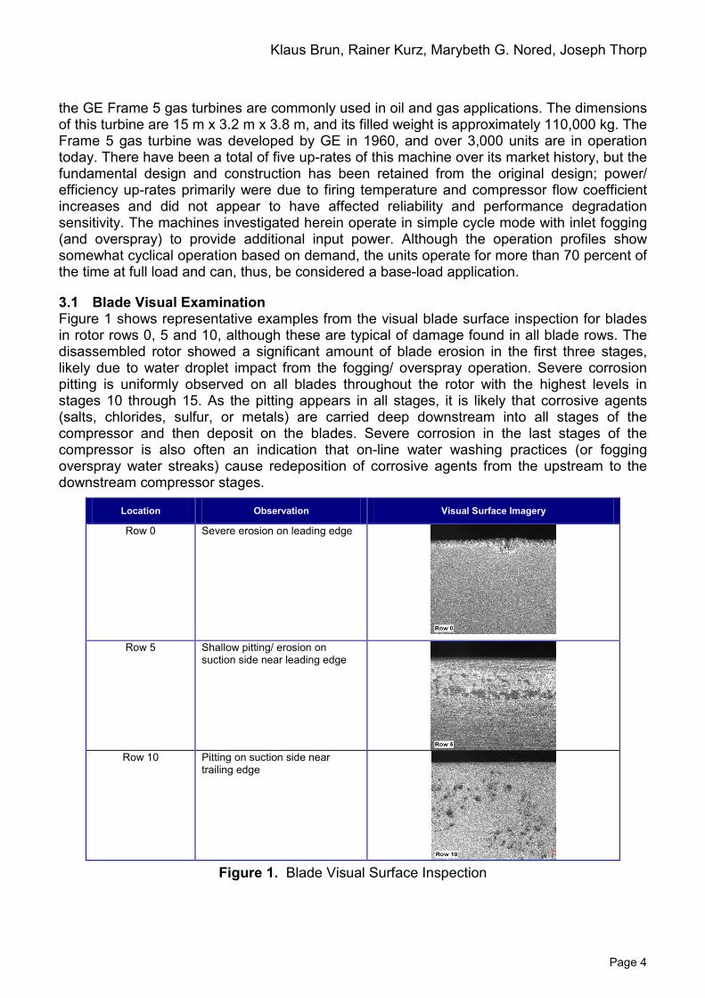
3.1 Blade Visual Examination Figure 1 shows representative examples from the visual blade surface inspection for blades in rotor rows 0, 5 and 10, although these are typical of damage found in all blade rows. The disassembled rotor showed a significant amount of blade erosion in the first three stages, likely due to water droplet impact from the fogging/ overspray operation. Severe corrosion pitting is uniformly observed on all blades throughout the rotor with the highest levels in stages 10 through 15. As the pitting appears in all stages, it is likely that corrosive agents (salts, chlorides, sulfur, or metals) are carried deep downstream into all stages of the compressor and then deposit on the blades. Severe corrosion in the last stages of the compressor is also often an indication that on-line water washing practices (or fogging overspray water streaks) cause redeposition of corrosive agents from the upstream to the downstream compressor stages.
Location Observation Visual Surface Imagery
Row 0 Severe erosion on leading edge
Row 5 Shallow pitting/ erosion on
suction side near leading edge
Row 10 Pitting on suction side near
trailing edge
Figure 1. Blade Visual Surface Inspection
Inlet Fogging and Overspray Impact on Industrial Gas Turbine Life and Performance
Page 5
3.2 Materials Analysis Compressor degradation is principally caused by loss of material on the leading and trailing edges of the blades (corrosion, erosion, and sand blasting) and surface fouling (buildup of material and roughening) on the airfoils. All degradation affects the blade’s ability to guide the flow. Furthermore, uneven blade corrosion, erosion, and fouling can lead to an increase in rotor unbalance, which will cause a performance loss due to blade clearance gap widening. A first step in a performance evaluation of any gas turbine is the determination of levels of fouling, erosion, and corrosion through a compressor material investigation. A material analysis was performed on the subject gas turbines to determine the cause of the rapid performance deterioration of these machines. The materials investigation program consisted of: 1. A visual material surface inspection of the rotor (and blades) sent for overhaul to quantify
the level of corrosion and pitting damage. 2. A collection of axial compressor blade surface deposit specimens from the rotor for
chemical material constituent analysis. 3. Visual and chemical analyses of typical gas turbine inlet filter material to determine the
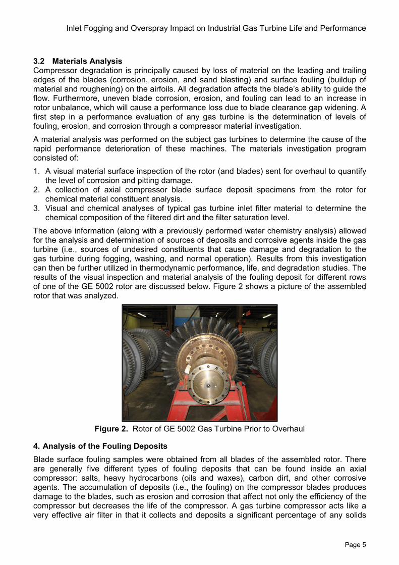
chemical composition of the filtered dirt and the filter saturation level. The above information (along with a previously performed water chemistry analysis) allowed for the analysis and determination of sources of deposits and corrosive agents inside the gas turbine (i.e., sources of undesired constituents that cause damage and degradation to the gas turbine during fogging, washing, and normal operation). Results from this investigation can then be further utilized in thermodynamic performance, life, and degradation studies. The results of the visual inspection and material analysis of the fouling deposit for different rows of one of the GE 5002 rotor are discussed below. Figure 2 shows a picture of the assembled rotor that was analyzed.
Figure 2. Rotor of GE 5002 Gas Turbine Prior to Overhaul
4. Analysis of the Fouling Deposits Blade surface fouling samples were obtained from all blades of the assembled rotor. There are generally five different types of fouling deposits that can be found inside an axial compressor: salts, heavy hydrocarbons (oils and waxes), carbon dirt, and other corrosive agents. The accumulation of deposits (i.e., the fouling) on the compressor blades produces damage to the blades, such as erosion and corrosion that affect not only the efficiency of the compressor but decreases the life of the compressor. A gas turbine compressor acts like a very effective air filter in that it collects and deposits a significant percentage of any solids
Klaus Brun, Rainer Kurz, Marybeth G. Nored, Joseph Thorp
Page 6
that are carried by the ambient air and are ingested into the gas turbine inlet. Also, due to the heat of compression, the temperature of the air passing through the compressor will increase to above 600°F such that any solids or chemicals dissolved in the water will drop out and deposit on the compressor blades. Salts: Salts (and other chlorides) in combination with moisture are primarily responsible for metal surface pitting in gas turbine compressors. As one of the most common deposits, salts lead to the formation of the deposit of chlorides in microscopic surface cracks and subsequent subsurface corrosion (evidenced as characteristics pits (small holes) on the surface of the blades. Salts do not enter the gas turbine from the ambient air (as is typical in offshore applications) but would be introduced by the plant water (i.e., fogging and water wash). Oils and Waxes: Oils and waxes are usually residues from compressor washing or ambient air contamination. Generally, the components do not cause significant damage but can act as binding agents for dirt or sand in the compressor and, thus, can contribute to fouling. Carbon: Carbon (or coke) deposits on compressor blades indicate that exhaust gases from the gas turbine or other internal combustion engines are entering the axial compressor. Coking inside the rotor can also be caused by local overheating or lube oil leakage. Deposits will bind with oils to form a surface deposit on the blades, which is very hard to remove with on-line and off-line cleaning. Most will deposit in the first couple of stages of the compressor and will not be carried downstream. Dirt (Sands): Sand entering the compressor blades is a significant contributor to blade leading and trailing edge erosion and surface fouling. Sand is primarily introduced into the gas turbine through the inlet filter and is an indication of inadequate inlet filtration or filter dirt saturation. The likely source of any sand/ dirt particles entering the gas turbine at subject installation is from the inlet air as any water carried sand or dirt would have been captured by the high efficiency fogging water filter. Corrosive Agents: Other foreign corrosive agents, such as sulfur compounds, vanadium, or heavy metals are often introduced into the gas turbine compressor by pollutants in the ambient air. These types of components are usually found in areas with significant UHC air emissions.
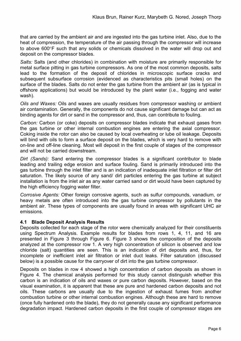
4.1 Blade Deposit Analysis Results Deposits collected for each stage of the rotor were chemically analyzed for their constituents using Spectrum Analysis. Example results for blades from rows 1, 4, 11, and 16 are presented in Figure 3 through Figure 6. Figure 3 shows the composition of the deposits analyzed at the compressor row 1. A very high concentration of silicon is observed and low chloride (salt) quantities are seen. This is an indication of dirt deposits and, thus, for incomplete or inefficient inlet air filtration or inlet duct leaks. Filter saturation (discussed below) is a possible cause for the carryover of dirt into the gas turbine compressor. Deposits on blades in row 4 showed a high concentration of carbon deposits as shown in Figure 4. The chemical analysis performed for this study cannot distinguish whether this carbon is an indication of oils and waxes or pure carbon deposits. However, based on the visual examination, it is apparent that these are pure and hardened carbon deposits and not oils. These carbons are usually due to the ingestion of exhaust fumes from another combustion turbine or other internal combustion engines. Although these are hard to remove (once fully hardened onto the blade), they do not generally cause any significant performance degradation impact. Hardened carbon deposits in the first couple of compressor stages are
Inlet Fogging and Overspray Impact on Industrial Gas Turbine Life and Performance
Page 7
also an indication that the compressor on-line and off-line water washing program is not effective.
Figure 3. Compressor Deposits in Row #1
Figure 4. Compressor Deposits in Row #4
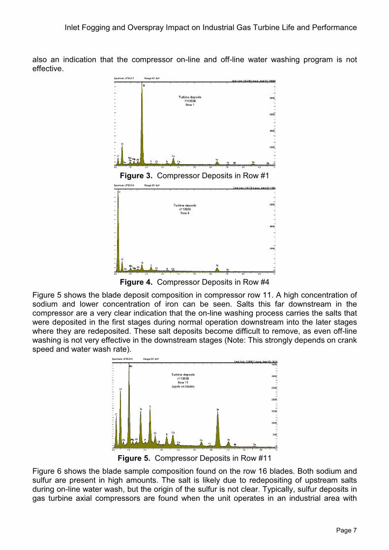
Figure 5 shows the blade deposit composition in compressor row 11. A high concentration of sodium and lower concentration of iron can be seen. Salts this far downstream in the compressor are a very clear indication that the on-line washing process carries the salts that were deposited in the first stages during normal operation downstream into the later stages where they are redeposited. These salt deposits become difficult to remove, as even off-line washing is not very effective in the downstream stages (Note: This strongly depends on crank speed and water wash rate).
Figure 5. Compressor Deposits in Row #11
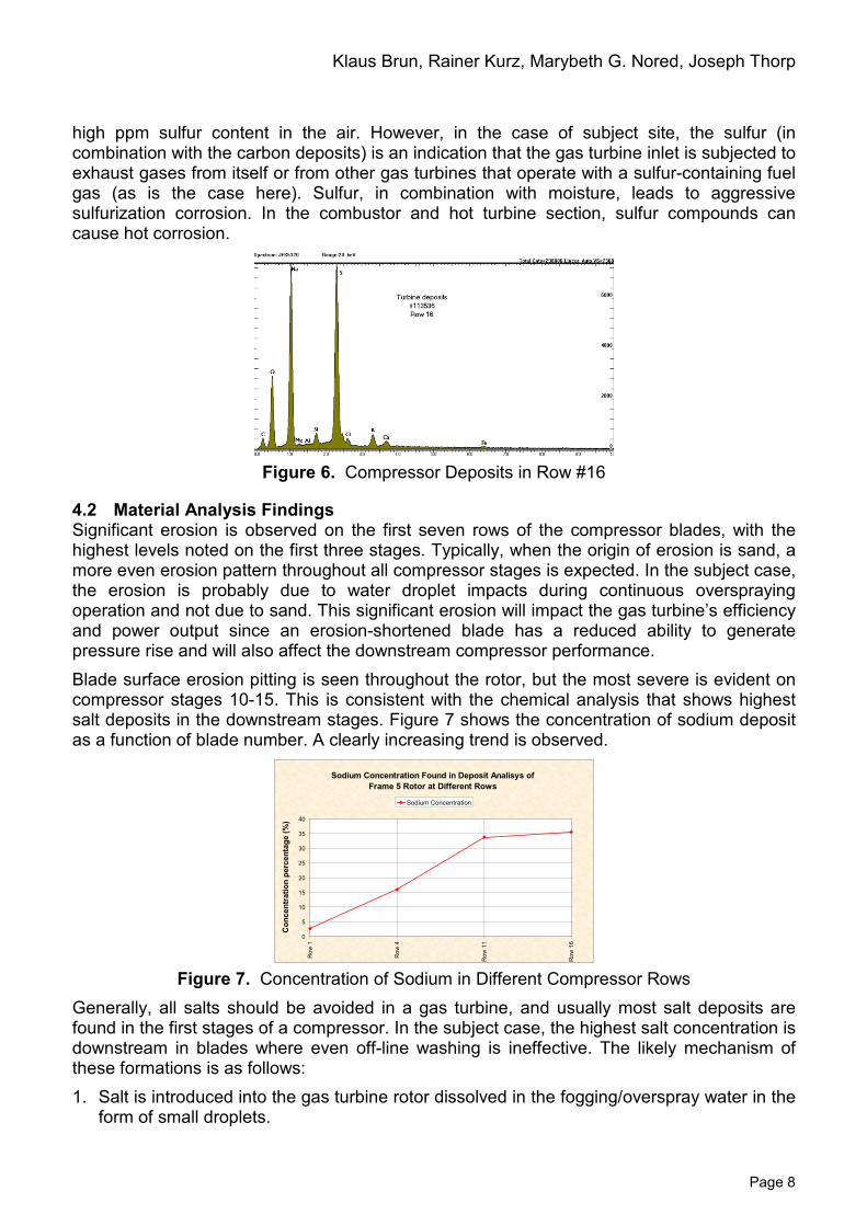
Figure 6 shows the blade sample composition found on the row 16 blades. Both sodium and sulfur are present in high amounts. The salt is likely due to redepositing of upstream salts during on-line water wash, but the origin of the sulfur is not clear. Typically, sulfur deposits in gas turbine axial compressors are found when the unit operates in an industrial area with
Klaus Brun, Rainer Kurz, Marybeth G. Nored, Joseph Thorp
Page 8
high ppm sulfur content in the air. However, in the case of subject site, the sulfur (in combination with the carbon deposits) is an indication that the gas turbine inlet is subjected to exhaust gases from itself or from other gas turbines that operate with a sulfur-containing fuel gas (as is the case here). Sulfur, in combination with moisture, leads to aggressive sulfurization corrosion. In the combustor and hot turbine section, sulfur compounds can cause hot corrosion.
Figure 6. Compressor Deposits in Row #16
4.2 Material Analysis Findings Significant erosion is observed on the first seven rows of the compressor blades, with the highest levels noted on the first three stages. Typically, when the origin of erosion is sand, a more even erosion pattern throughout all compressor stages is expected. In the subject case, the erosion is probably due to water droplet impacts during continuous overspraying operation and not due to sand. This significant erosion will impact the gas turbine’s efficiency and power output since an erosion-shortened blade has a reduced ability to generate pressure rise and will also affect the downstream compressor performance. Blade surface erosion pitting is seen throughout the rotor, but the most severe is evident on compressor stages 10-15. This is consistent with the chemical analysis that shows highest salt deposits in the downstream stages. Figure 7 shows the concentration of sodium deposit as a function of blade number. A clearly increasing trend is observed.
Figure 7. Concentration of Sodium in Different Compressor Rows
Generally, all salts should be avoided in a gas turbine, and usually most salt deposits are found in the first stages of a compressor. In the subject case, the highest salt concentration is downstream in blades where even off-line washing is ineffective. The likely mechanism of these formations is as follows: 1. Salt is introduced into the gas turbine rotor dissolved in the fogging/overspray water in the
form of small droplets.
Sodium Concentration Found in Deposit Analisys of Frame 5 Rotor at Different Rows
0
5
10
15
20
25
30
35
40
Row
1
Row
4
Row
11
Row
16
Con
cent
ratio
n pe
rcen
tage
(%)
Sodium Concentration
Inlet Fogging and Overspray Impact on Industrial Gas Turbine Life and Performance
Page 9
2. The salts deposit in the first stages of the compressor as the water evaporates due to compression heating.
3. Regular on-line washing removes the salts from the first stages and carries them downstream into the higher stages where they are redeposited.
4. Off-line washing is not efficient in the higher stages, especially when the crank speed is too high or when the flow rate is too low. (Operators often perform only one or two wash-rinse cycles until they notice no water discoloration. However, five to six thorough wash-rinse cycles are usually required to fully remove any salt deposits.)
The above findings indicate a number of problems with the gas turbine operations, namely: 1. Overspraying causes erosion of the compressor blades. 2. Fogging water has dissolved salts or other chlorides. 3. On-line and off-line washing methods are not adequate for the application. The inlet filters (may) be dirt saturated. (See discussion below.)
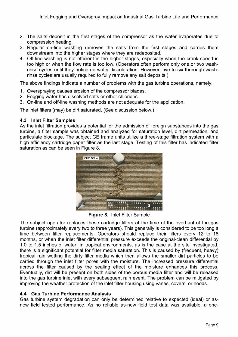
4.3 Inlet Filter Samples As the inlet filtration provides a potential for the admission of foreign substances into the gas turbine, a filter sample was obtained and analyzed for saturation level, dirt permeation, and particulate blockage. The subject GE frame units utilize a three-stage filtration system with a high efficiency cartridge paper filter as the last stage. Testing of this filter has indicated filter saturation as can be seen in Figure 8.
Figure 8. Inlet Filter Sample
The subject operator replaces these cartridge filters at the time of the overhaul of the gas turbine (approximately every two to three years). This generally is considered to be too long a time between filter replacements. Operators should replace their filters every 12 to 18 months, or when the inlet filter differential pressure exceeds the original-clean differential by 1.0 to 1.5 inches of water. In tropical environments, as is the case at the site investigated, there is a significant potential for filter media saturation. This is caused by (frequent, heavy) tropical rain wetting the dirty filter media which then allows the smaller dirt particles to be carried through the inlet filter pores with the moisture. The increased pressure differential across the filter caused by the sealing effect of the moisture enhances this process. Eventually, dirt will be present on both sides of the porous media filter and will be released into the gas turbine inlet with every subsequent rain event. The problem can be mitigated by improving the weather protection of the inlet filter housing using vanes, covers, or hoods.
4.4 Gas Turbine Performance Analysis Gas turbine system degradation can only be determined relative to expected (ideal) or as-new field tested performance. As no reliable as-new field test data was available, a one-
Klaus Brun, Rainer Kurz, Marybeth G. Nored, Joseph Thorp
Page 10
dimensional thermodynamics model was developed to predict the ideal site gas turbine performance in order to determine the gas turbine relative degradation performance. Basic thermodynamics calculations and evaluation of the gas turbine’s manufacturer performance curves (stage characteristics and total gas turbine) were utilized to build a model that estimates gas turbine power output, efficiency, for dry, saturation fogging, and overspray scenarios. The model assumes 95 percent fogging efficiency to saturation and 85 percent overspray efficiency. Wet bulb temperatures were determined for standard atmospheric air, and air saturation levels were determined between each compressor stage. The primary objective of these computations is to evaluate the ideally expected site gas turbine performance and compare it to the actual numbers to determine relative degradation. The results also provide an indication of the relative benefit of fogging and overspray for a given ambient and operating condition. Obviously, these calculations are dependent on the ambient conditions (temperature, pressure, and relative humidity). Thus, representative days where chosen for each month of the year for the analysis based on actual site data.
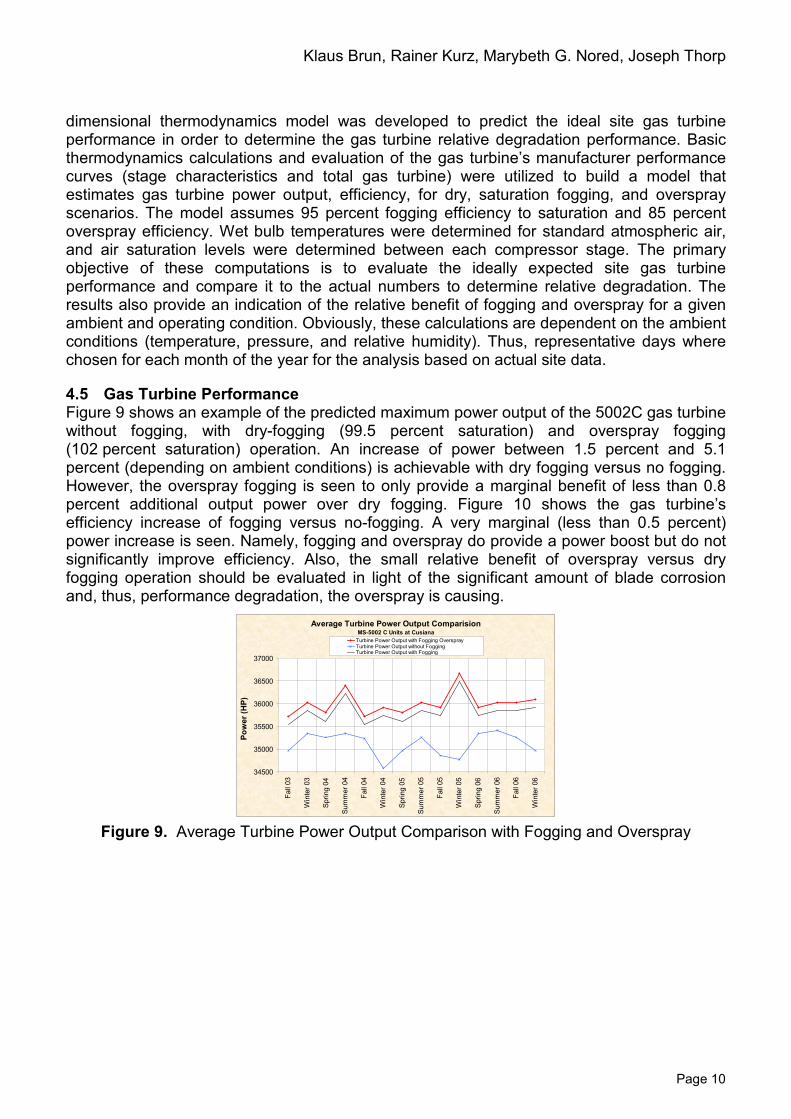
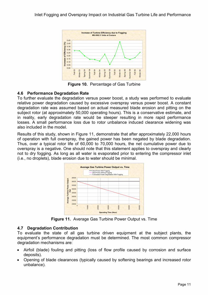
4.5 Gas Turbine Performance Figure 9 shows an example of the predicted maximum power output of the 5002C gas turbine without fogging, with dry-fogging (99.5 percent saturation) and overspray fogging (102 percent saturation) operation. An increase of power between 1.5 percent and 5.1 percent (depending on ambient conditions) is achievable with dry fogging versus no fogging. However, the overspray fogging is seen to only provide a marginal benefit of less than 0.8 percent additional output power over dry fogging. Figure 10 shows the gas turbine’s efficiency increase of fogging versus no-fogging. A very marginal (less than 0.5 percent) power increase is seen. Namely, fogging and overspray do provide a power boost but do not significantly improve efficiency. Also, the small relative benefit of overspray versus dry fogging operation should be evaluated in light of the significant amount of blade corrosion and, thus, performance degradation, the overspray is causing.
Figure 9. Average Turbine Power Output Comparison with Fogging and Overspray
Average Turbine Power Output ComparisionMS-5002 C Units at Cusiana
34500
35000
35500
36000
36500
37000
Fall
03
Win
ter 0
3
Sprin
g 04
Sum
mer
04
Fall
04
Win
ter 0
4
Sprin
g 05
Sum
mer
05
Fall
05
Win
ter 0
5
Sprin
g 06
Sum
mer
06
Fall
06
Win
ter 0
6
Pow
er (H
P)
Turbine Power Output with Fogging Overspray Turbine Power Output without Fogging Turbine Power Output with Fogging
Inlet Fogging and Overspray Impact on Industrial Gas Turbine Life and Performance
Page 11
Figure 10. Percentage of Gas Turbine
4.6 Performance Degradation Rate To further evaluate the degradation versus power boost, a study was performed to evaluate relative power degradation caused by excessive overspray versus power boost. A constant degradation rate was assumed based on actual measured blade erosion and pitting on the subject rotor (at approximately 50,000 operating hours). This is a conservative estimate, and in reality, early degradation rate would be steeper resulting in more rapid performance losses. A small performance loss due to rotor unbalance induced clearance widening was also included in the model. Results of this study, shown in Figure 11, demonstrate that after approximately 22,000 hours of operation with full overspray, the gained power has been negated by blade degradation. Thus, over a typical rotor life of 60,000 to 70,000 hours, the net cumulative power due to overspray is a negative. One should note that this statement applies to overspray and clearly not to dry fogging. As long as all water is evaporated prior to entering the compressor inlet (i.e., no droplets), blade erosion due to water should be minimal.
Figure 11. Average Gas Turbine Power Output vs. Time
4.7 Degradation Contribution To evaluate the state of all gas turbine driven equipment at the subject plants, the equipment’s performance degradation must be determined. The most common compressor degradation mechanisms are:
• Airfoil (blade) fouling and pitting (loss of flow profile caused by corrosion and surface deposits).
• Opening of blade clearances (typically caused by softening bearings and increased rotor unbalance).
Increase of Turbine Efficiency due to FoggingMS-5002 C Units at Cusiana
0.00
0.05
0.10
0.15
0.20
0.25
0.30
0.35
0.40
0.45
Fall
03
Win
ter 0
3
Spr
ing
04
Sum
mer
04
Fall
04
Win
ter 0
4
Spr
ing
05
Sum
mer
05
Fall
05
Win
ter 0
5
Spr
ing
06
Sum
mer
06
Fall
06
Win
ter 0
6
Incr
ease
of E
ffcie
ncy
(%)
Average Gas Turbine Power Output vs. Time
33000
33500
34000
34500
35000
35500
36000
36500
0
1000
0
2000
0
3000
0
4000
0
5000
0
6000
0
Operating Time (Hour)
Ave
rage
Tur
bine
Pow
er O
utpu
t (h
p)
Ideal Power With FoggingIdeal Power Without FoggingForecasted Power Degradation With Fogging
Klaus Brun, Rainer Kurz, Marybeth G. Nored, Joseph Thorp
Page 12
• Leading and trailing edge erosion (caused by mechanical solid and liquid impacts on the rotor blades).
An analysis of the relative influence factors of degradation was performed for the subject units to determine the principal causes of performance losses. The methodology for this analysis was described by Brun, et al. (2008). This data is based on measured clearances (from the inspected rotor) and fouling deposits. As limited internal aerodynamics data was available for this turbine, the subject analysis results should be considered approximations only. The percentages below present values of total degradation at just prior to overhaul, which is approximately 10 percent (3,600 HP). These results are shown in Table 1.
Table 1. Performance Losses by Source Relative
Influence Power
Loss (HP) Blade Surface Fouling 10% 360 Surface Corrosion/ Pitting 15% 540 Blade Edge Erosion 35% 1,260 Rotor Clearances 30% 1,080 System Losses 10% 360
Clearly, blade erosion due to fogging overspray operation is seen to be the largest contributor to losses. Blade erosion is also usually a significant cause for rotor unbalance and, thus, increased blade clearances. Blade surface fouling at subject site appears to be primarily due to inlet filter saturation, while blade surface corrosion and pitting is primarily due to salt carryover from plant water. Both of these detrimental effects can relatively easily be mitigated by more frequent inlet filter cleaning and water quality improvement.
4.8 Performance Analysis Findings The inlet fogging systems at the subject site have a demonstrated potential of about one to five percent power augmentation and negligible efficiency increases in the gas turbine when directly compared to dry operation. However, the added long-term degradation of gas turbine performance caused by the water overspray has likely reduced the output power more than any beneficial power boost from this operation. This, in combination with the marginal quality water (discussed below) used for fogging and overspray is the likely primary cause for the rapid performance deterioration of all gas turbines. While the power gain from saturation (or slightly below saturation fogging) may be beneficial, it is unlikely that the small power increase (below one percent) from overspray warrants the detrimental effect on the gas turbine. Based on the local average temperatures and relative humidity over the last four years, the investigated locations had the potential for an average 12.1ºF gas turbine inlet temperature reduction when fully utilizing their fogging and overspraying system. This temperature reduction translates directly into an actual power augmentation (including all losses and ambient conditions) of approximately 3.4 percent and increased efficiency of 0.21 percent over the last four years. In the same time frame, the average total degradation of the gas turbines was between six to ten percent in both power and efficiency, thus, negating any power gain from the fogging and overspray system.
4.9 Water Treatment Plugging of spray nozzles in the fogging system and deposits of salts on the compressor blades are a strong indication for solid and salt carryover from the water treatment system. Any undesirable water soluble and solid constituents passing through the water treatment system into the fogging system will likely deposit in the gas turbine’s axial compressor. Even
Inlet Fogging and Overspray Impact on Industrial Gas Turbine Life and Performance
Page 13
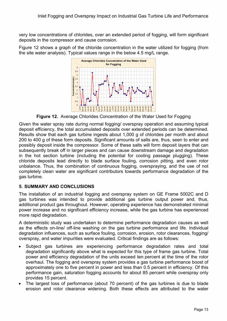
very low concentrations of chlorides, over an extended period of fogging, will form significant deposits in the compressor and cause corrosion. Figure 12 shows a graph of the chloride concentration in the water utilized for fogging (from the site water analysis). Typical values range in the below 4.5 mg/L range.
Figure 12. Average Chlorides Concentration of the Water Used for Fogging
Given the water spray rate during normal fogging/ overspray operation and assuming typical deposit efficiency, the total accumulated deposits over extended periods can be determined. Results show that each gas turbine ingests about 1,000 g of chlorides per month and about 200 to 400 g of these form deposits. Significant amounts of salts are, thus, seen to enter and possibly deposit inside the compressor. Some of these salts will form deposit layers that can subsequently break off in larger pieces and can cause downstream damage and degradation in the hot section turbine (including the potential for cooling passage plugging). These chloride deposits lead directly to blade surface fouling, corrosion pitting, and even rotor unbalance. Thus, the combination of continuous fogging, overspraying, and the use of not completely clean water are significant contributors towards performance degradation of the gas turbine.
5. SUMMARY AND CONCLUSIONS The installation of an industrial fogging and overspray system on GE Frame 5002C and D gas turbines was intended to provide additional gas turbine output power and, thus, additional product gas throughout. However, operating experience has demonstrated minimal power increase and no significant efficiency increase, while the gas turbine has experienced more rapid degradation. A deterministic study was undertaken to determine performance degradation causes as well as the effects on-line/ off-line washing on the gas turbine performance and life. Individual degradation influences, such as surface fouling, corrosion, erosion, rotor clearances, fogging/ overspray, and water impurities were evaluated. Critical findings are as follows:
• Subject gas turbines are experiencing performance degradation rates and total degradation significantly above what is expected for this type of frame gas turbine. Total power and efficiency degradation of the units exceed ten percent at the time of the rotor overhaul. The fogging and overspray system provides a gas turbine performance boost of approximately one to five percent in power and less than 0.5 percent in efficiency. Of this performance gain, saturation fogging accounts for about 85 percent while overspray only provides 15 percent.
• The largest loss of performance (about 70 percent) of the gas turbines is due to blade erosion and rotor clearance widening. Both these effects are attributed to the water
Average Chlorides Concetration of the Water Used for Fogging
0
0.5
1
1.5
2
2.5
3
3.5
4
4.5
5
Jul-0
2
Sep
-02
Nov
-02
Jan-
03
Mar
-03
May
-03
Jul-0
3
Sep
-03
Nov
-03
Jan-
04
Mar
-04
May
-04
Jul-0
4
Sep
-04
Nov
-04
Jan-
05
Mar
-05
May
-05
Jul-0
5
Sep
-05
Nov
-05
Jan-
06
Mar
-06
May
-06
Jul-0
6
Sep
-06
Nov
-06
Con
cetr
atio
n(m
g/L)
Klaus Brun, Rainer Kurz, Marybeth G. Nored, Joseph Thorp
Page 14
overspray operation of the gas turbine. Surface fouling and pitting also contributed about 20 percent to the total performance degradation.
• The performance degradation due to water overspray negates any boost in performance of the fogging system after only about 22,000 hours of operation of continuous overspray. Without overspray, the performance degradation of the gas turbines would be in line with similar frame gas turbine units.
• Significant deposits of chloride (salts) are found on the gas turbine compressor blades. (salts introduced into each gas turbine at approximately one kg per month based on continuous operation). These salts originate in the fogging/ overspray water that is passed through the water treatment system. These deposits are directly responsible for blade corrosion and surface pitting. Also, plugged fogging nozzles lead to an uneven fogging pattern with a wide distribution of droplet sizes and possible water streaks.
• The heaviest blade surface pitting and the highest concentration of chlorides are found on the downstream compressor blades rather than on the upstream blades. This is uncommon but is a strong indication that the salts are carried downstream and redeposited by inefficient on-line water cleaning. Once the salts are deposited far downstream in the compressor, off-line cleaning is ineffective.
• Sulfur and carbon compounds were found in the rotor deposits. These are probably due to the ingestion of exhaust gas from other combustion gas turbines or engines into the inlet of the subject gas turbine. Sulfur in combination with moisture enhances cold corrosion in the compressor.
• The on-line and off-line compressor washing program is not fully effective, as hardened deposits of salts, carbon, and sulfur were found on the compressor rotor. Also, infrequently performed solid washing of the gas turbine compressors cause significant blade leading/ trailing edge erosion throughout the compressor, opens blade clearance gaps, and removes corrosion protective coatings from the compressor blades.
• Inlet filter samples analyzed show dirt saturation and dirt carryover. This is likely caused by insufficient filter weather protection, cleaning, or replacement of the filter cartridges. Blade deposit samples of the first couple of compressor rows showed sand (silicon oxide) constituents, which is consistent with this observation.
6. REFERENCES [1] Diakunchak, I. S. 1991, “Performance Degradation in Industrial Gas Turbines,” ASME
Paper 91-GT-228. [2] Kurz, R., Brun, K., 2000, “Degradation in Gas Turbine Systems,” ASME Paper 2000-GT-
0345. [3] Brun, K., Kurz, R., 1998, “Measurement Uncertainties Encountered During Gas Turbine
Driven Compressor Field Testing,” ASME Paper 98GT-1. [4] Bakken, L. E., Skorping, R., 1996 “Optimum Operation and Maintenance of Gas Turbines
Offshore,” ASME Paper 96-GT-273. [5] Boyle, R. J., 1994, “Prediction of Surface Roughness and Incidence Effects on Turbine
Performance,” TransASME, J.Turbo, Vol. 116, pp 745-751. [6] Elrod, W. C., King, P. I., Poniatowsky, E. M., 1990, “Effects of Roughness, Freestream
Turbulence, and Incidence Angle on the Performance of a 2D Compressor Cascade,” ASME Paper 90-GT-208.
[7] Aker, G. F., Saravanamuttoo, H. I. H., 1998, “Predicting the Gas Turbine Performance Degradation Due to Compressor Fouling Using Computer Simulation Techniques,” ASME Paper 88-GT-206.
Inlet Fogging and Overspray Impact on Industrial Gas Turbine Life and Performance
Page 15
[8] Frith, P. C., 1992, “The Effect of Compressor Rotor Tip Crops on Turboshaft Engine Performance,” ASME Paper 92-GT-83.
[9] Howard, M. A., Ivey, P. C., Barton, J. P., Young, K. F., 1994, “Endwall Effects at Tow Tip Clearances in a Multistage Axial Flow Compressor with Controlled Diffusion Blading,” TransASME, J.Turbo, Vol. 116, pp. 635-647.
[10] Kind, R. J., Serjak, P. J., Abbot, M. W. P., 1996, “Measurements and Predictions of the Effects of Surface Roughness on Profile Losses and Deviation in a Turbine Cascade,” ASME Paper 96-GT-203.
[11] Pinson, M., Wang, T., 1994, “Effects of Leading-Edge Roughness on Fluid Flow and Heat Transfer in the Transitional Boundary Layer of a Flat Plate,” ASME Paper 94-GT-326.
[12] Spakovszky, Z. S., Ger, J. B., Sharma, O. P., Paduano, J. D., Epstein, A. H., Greitzer, E. M., 1999, “Influence of Compressor Deterioration on Engine Dynamic Behavior and Transient Stall Margin,” ASME Paper 99-GT-439.
[13] Singh, D., Hamed, A., Tabakoff, W., 1996, “Simulation of Performance Deterioration in Eroded Compressors,” ASME Paper 96-GT-422.
[14] Stalder, J. P., 1998, “Gas Turbine Compressor Washing State of the Art Field Experiences,” ASME Paper 98-GT-420.
[15] Storer, J. A., Cumpsty, N. A., 1994, “An Approximate Analysis and Prediction Method for Tip Clearance Loss in Axial Compressors,” TransASME, J.Turbo, Vol. 116, pp. 648-656.
[16] Tarabrin, A. P., Schurovsky, V. A., Bodrow, A. I., Stalder, J. P., 1998, “Influence of Axial Compressor Fouling on Gas Turbine Unit Performance Based on Different Schemes and with Different Initial Parameters,” ASME Paper 98-GT-416.
[17] Horlock, J. H., 2001, “Compressor Performance with Water Injection,” ASME Paper 2001-GT-0343.
[18] Zheng, Q., Sun, Y., Li, S., and Wang, Y., 2002, “Thermodynamic Analysis of Wet Compression Process in the Compressor of Gas Turbine,” ASME Paper GT-2002-30590.
[19] Chaker, M., Meher-Homji, C. B., and Mee III, T. R., 2002, “Inlet Fogging of Gas Turbine Engines,” Part A: Fog Droplet Thermodynamics, Heat Transfer and Practical Considerations,” ASME Paper GT-2002-30562.
[20] Chaker, M., Meher-Homji, C. B., and Mee III, T. R., 2002, “Inlet Fogging of Gas Turbine Engines,” Part B: Fog Droplet Sizing Analysis, Nozzle Type, Measurement and Testing,” ASME Paper GT-2002-30563.
[21] Bhargava, R., Bianchi, M., Melino, F., and Peretto, A., 2003, “Parametric Analysis of Combined Cycles Equipped with Inlet Fogging,” ASME Paper GT-2003-38187.
[22] Bhargava, R., Bianchi, M., Melino, F., Peretto, A., Meher-Homji, C. B., and Chaker, M. A., 2003, “Inlet Fogging for Gas Turbine Power Augmentation – A State-of-the-Art Review,” Proceedings, International Conference on Power Engineering-03 (ICOPE-03), Kobe, Japan.
[23] Hartel, C. and Pfeiffer, P., 2003, “Model Analysis of High-Fogging Effects on the Work of Compression,” ASME Paper GT-2003-38117.
[24] White, A. J. and Meacock, A. J., 2003, “An Evaluation of the Effects of Water Injection on Compressor Performance,” ASME Paper GT-2003-38237.
[25] Bhargava, R., Bianchi, M., Melino, F., Peretto, A., Meher-Homji, C. B., and Chaker, M. A., 2003, “Inlet Fogging for Gas Turbine Power Augmentation – A State-of-the-Art Review,” Proceedings, International Conference on Power Engineering-03 (ICOPE-03), Kobe, Japan.
[26] Bhargava, R. and Meher-Homji, C. B., 2002, “Parametric Analysis of Existing Gas Turbines with Inlet Evaporative and Overspray Fogging,” ASME Paper GT-2002-30560.
Klaus Brun, Rainer Kurz, Marybeth G. Nored, Joseph Thorp
Page 16
[27] Jolly, S., 2003, “Inlet Fogging and Wet Compression Technology,” ASME Paper GT-2003-38209.
[28] Chaker, M., Meher-Homji, C. B., and Mee, T., 2002, “Inlet Fogging of Gas Turbine Engines-Part I, Part II,” ASME Paper GT-2002-30562.
[29] Brun, K., Gonzalez, L.E., and Platt, J.P., “Impact of Continuous Overspray Operation on GE5002 Gas Turbine Life and Performance,” ASME Paper GT-2008-50207.