innovating for energy efficiency - olpi-durr.it energy products... · innovating for ......
TRANSCRIPT

www.durr.com
InnovatIng for energy effIcIency
ENERGY EFFICI
ENCYGR
EEN
TECHNOLOGY
CONVERSIONSTORAGE
EXCHANGE
POWER GENERATION
EXHA
UST
GAS P
URIFICATION

22
EnvironmEntal ProtEctionSuStaInable envIronmental ProtectIon
our expertise: energy efficiency
Compact Power System
OrganicRankineCycle (ORC)
Absorption, thermal andcatalytic oxidation, heat recovery
Cleaning ofwaste (saline liquids, gases containing silane)
Heat exchangersand equipment
Heat pumps and re-frigeration systems
Mobile heatstorage
EXHA
UST
GAS P
URIFICATION POWER GENERATION
STORAGE
CONVERSION
EXCHANGE
GREE
N TE
CHNOLOGY
ENERGY EFFICI
ENCY
Dürr, a mechanical and systems engineering group, is a global leader in numerous industrial segments and markets. Within the Dürr Group, four divisions operate within the various global markets.
The Clean Technology Systems division specializes in processes to improve energy efficiency and exhaust air purification.
The potential from the use of untapped energy sources is immense. Energy efficiency means making mean-ingful use of existing waste heat and applying it more effectively. Together with partner companies, Dürr offers a variety of innovative energy efficiency technologies that seamlessly complement each other. Our products use excess process heat, waste heat, as well as conventional and alternative fuels to store, relay, or transform energy or to convert it into electricity.

33
Ecopure exhauSt aIr PurIfIcatIonEcopure exhaust air purification
Dürr offers the latest system technology, permitting efficient removal of exhaust gases and res-idues, reducing energy consumption, and ensuring high process reliability. As a system partner, Dürr combines technical know-how with global availability to support customers worldwide.
» Ecopure KPR – VOC Concentrator
» Ecopure TAR – Recuperative Thermal Exhaust Air Purification
» Ecopure RTO – Regenerative Thermal Oxidation
» Ecopure SCR – Selektive Catalytic Reduction
» Ecopure VAR – Incineration of Exhaust Gases and Residual Liquids
» Ecopure HPX – High-Pressure Catalytic Oxidation
our environment needs exhaust air purification systems
The key tasks include:
» Cleaning exhaust air from production processes » Removing exhaust gases from the reaction processes » Complying with statutory guidelines for emission control while reducing the use of primary energy sources
» Eliminating unwanted odors
Production processes produce exhaust gases and vapors that can harm the environment if not treated. In order to protect the environment, these exhaust gases and vapors must be removed from the exhaust air before the process air is released into the atmosphere.

4
organic rankine cycle (orc) is a key technology for electricity generation from decentralized heat sources. Due to its efficiency and flexibility, unused thermal energy can be profitably utilized using orc technology with a temperature range of between 90 and 600 °c.
areas of application
Dürr Cyplan ORC systems can be used with many different waste heat sources. Currently, the most attractive waste heat sources are those available continuously and in which users receive payment for the electricity generated. These sources include stationary combustion engines running on renewable raw materials such as bio-gas plants, gas tur-bines, or wood-burning appliances. The higher the electric-ity prices and the greater the availability of waste heat, the faster the investment in an ORC system is amortized.
orcorganIc rankIne cycleOrganic rankine cycle
COMBINED RECUPERATOR/CONDENSERYour benefits:» Compact system design» Minimal pressure losses» Ideal heat transfer
CONTROL PANEL/CONTROLLERYour benefits:» Fully automated operation» Remote monitoring» Compact module ready to connect
DIRECT EVAPORATORYour benefits:» Simple incorporation without intermediate circuit» Greater safety» Better energy utilization» Easy maintenance
HERMETICALLY SEALED TURBOGENERATORYour benefits:» No additional lubricating circuit» Swivel-mounted turbine support for simple maintenance» Greater efficiency through freely selectable operating speed» Ideal blades for high pressure conditions
Your benefits:» Power-heat coupling of up to 90 °C possible
EXHAUST GAS OUTLET
EXHAUST GAS INLET
RESIDUAL HEAT
MAINSCurrent

55
aDvantageS
» Electricity generation using residual heat from combustion or production processes
» Pre-tested compact modules for a broad temperature and performance range
» High electrical efficiency with minimum power consumption
» Easy system integration thanks to direct evaporation technology
» Optional utilization of condensation heat » Fully automatic operation and remote monitoring
the orc system
The ORC process is a thermal cycle which uses thermal energy to generate electricity. Hot exhaust gases flow from the heat source (e.g. combustion engine) into the ORC module where the working medium is evaporated by heat energy. Steam flows under pressure into a turbo genera-tor where a portion of the heat energy is converted into electricity. Finally, the steam is condensed in a condenser where cooling re-liquefies the steam. The liquid working medium is pumped back into the evaporator.
ORC systems are available as standardized compact modules in electrical power performance sizes of 70, 120, 300 and 500 kW.
Both high and low-temperature heat sources can be used for power generation.
In high-temperature units, the condensation heat can be supplied at a temperature which enables further use and thus combined heat and power operation.
» ORC 70 kW compact module

6
the compact Power System (cPS) is based on gas turbine technology, combining highly efficient power and heat exchanger for decentralized production of electricity and heat by converting energy from low calorific gases or for cleaning solvent-laden air.
areas of application
The CPS systems are versatile. For example, CPS systems can be used for steam generation, heating, air conditioning, drying, CO2 fertilization, or in combination with a downstream ORC process or heat pumps.
CPS can operate with low emissions on a wide range of fuels such as natural gas, biogas, or low calorific gas and liquid fuels such as diesel or methanol.
cPScomPact Power SyStemCompaCt power SyStem
7
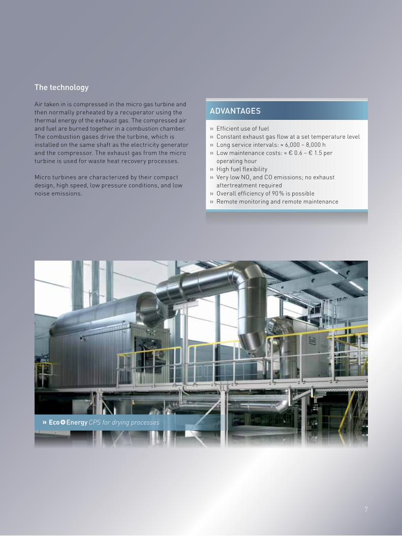
» CPS for drying processes
aDvantageS
» Efficient use of fuel » Constant exhaust gas flow at a set temperature level » Long service intervals: ≈ 6,000 – 8,000 h » Low maintenance costs: ≈ € 0.6 – € 1.5 per operating hour
» High fuel flexibility » Very low NOx and CO emissions; no exhaust aftertreatment required
» Overall efficiency of 90 % is possible » Remote monitoring and remote maintenance
the technology
Air taken in is compressed in the micro gas turbine andthen normally preheated by a recuperator using thethermal energy of the exhaust gas. The compressed airand fuel are burned together in a combustion chamber.The combustion gases drive the turbine, which is installed on the same shaft as the electricity generator and the compressor. The exhaust gas from the micro turbine is used for waste heat recovery processes.
Micro turbines are characterized by their compact design, high speed, low pressure conditions, and low noise emissions.
8
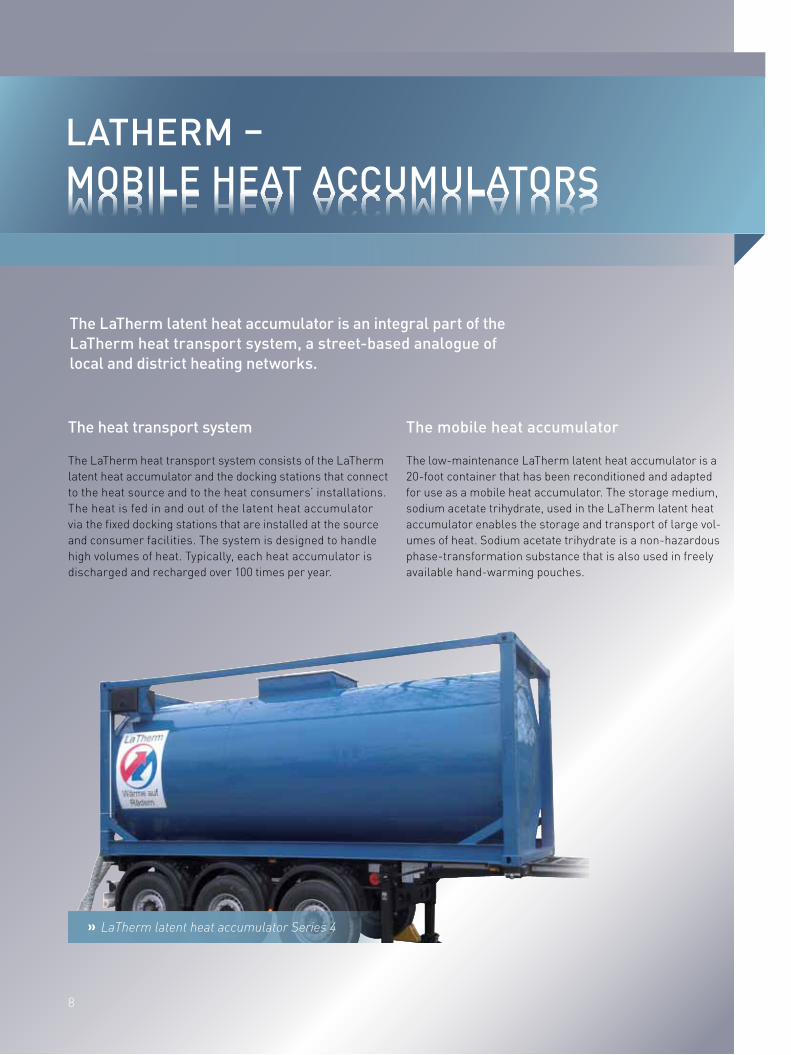
latherm –mobIle heat accumulatorSMobile heat accuMulators
the latherm latent heat accumulator is an integral part of the latherm heat transport system, a street-based analogue of local and district heating networks.
the heat transport system
The LaTherm heat transport system consists of the LaTherm latent heat accumulator and the docking stations that connect to the heat source and to the heat consumers’ installations. The heat is fed in and out of the latent heat accumulator via the fixed docking stations that are installed at the source and consumer facilities. The system is designed to handle high volumes of heat. Typically, each heat accumulator is discharged and recharged over 100 times per year.
» LaTherm latent heat accumulator Series 4
the mobile heat accumulator
The low-maintenance LaTherm latent heat accumulator is a 20-foot container that has been reconditioned and adapted for use as a mobile heat accumulator. The storage medium, sodium acetate trihydrate, used in the LaTherm latent heat accumulator enables the storage and transport of large vol-umes of heat. Sodium acetate trihydrate is a non-hazardous phase-transformation substance that is also used in freely available hand-warming pouches.

9
» LaTherm heat management software
aDvantageS
» Reduction of fuel consumption » Long-term predictability of heat costs » Generation of usable low-carbon heat from waste heat » Regional heat supply on the doorstep » Visible, positive public-image solution
The storage capacity of the mobile heat accumulator is up to 2.5 MWh with full charge and deep discharge. In the typical application case, 2 MWh are stored. The charge takes 12 hours, while the discharge takes no more than 24 hours under optimal conditions.
target group
Any company that produces unused residual heat, for ex-ample a waste incineration or bio-gas plant, can become a regional heat supplier using the LaTherm heat transport system. The heat source should provide at least 250 kW thermal output at minimum 95 °C.
Heat customers are high-volume consumers, whose heat-ing systems work optimally in the low temperature range. Examples include swimming pools, logistics centers, schools, and office buildings. Heat consumption should be at least 500 MWh.
remote monitoring
The mobile LaTherm latent heat accumulator is equipped with a heat meter, which collects billing-grade heat con-sumption data. An integrated electronic device sends this heat consumption data to the LaTherm data center. Here, the data is available to the operators of the mobile heat-ing network for billing purposes, but also for planning of transport logistics.

10
technology
State-of-the-art heat pumps and refrigerant units for applications in industrial and building automation systems. Heating-water temperatures of up to 90 °C can be reached with the proven thermeco2 systems. This paves the way for many new applications for energy-efficient and sustainable production, particularly in the indus-trial sector.
Sustainable co2 refrigerant
The use of the natural refrigerant R744 (CO2) renders the thermeco2 systems absolutely environmentally friendly. CO2 is climate neutral (GWP = 1) and does not contribute to ozone depletion (ODP = 0). The currently widely used fluorinated refrigerants contribute to the greenhouse effect and so to the acceleration of climate change. Therefore, HCFC refrigerants such as R22, which causes ozone depletion, are only authorized for use until the end of 2014. Other widely used HFC refrigerants are also the subject of controversy and are once again being tested with the coming tightening of the F-Gas Regulation. thermeco2 systems that work with harmless CO2, are therefore a long-term reliable alter-native.
thermea high-temperature heat pumps, refrigerant units, and compressed-air refrigerant dryers using environmentally friendly refrigerant co2
THERMEA
» thermeco2 HHS 1000, heating capacity 1,000 kW awarded the Kältepreis (award for environmentally friendly innovation in refrigeration technology) by the German Federal Ministry for the Environment

11
aDvantageS
» Thermal- and process-heat generation » Use of heat sources up to 35 °C (low-temperature residual heat: cooling water, waste water, exhaust air)
» An alternative for the utilization of heat generated through air-conditioning and process cooling up to -10 °C
» Compressed-air drying » Extremely operator-friendly refrigerant » Refrigerant does not fall under F-Gas Regulation (future-proof investment)
» Versatile applications in building automation (supports concepts for sustainable building, for example according to German Sustainable Building Council standards)
thermeco2 high-temperature heat pumps and refrigerant units
The thermeco2 HHR / HHS series serves a heat output range from 45 to 1000 kW. The refrigerant version can ensure temperatures down to -10 °C. Even in the case of refrigerant units, the process heat supply can regularly result in flow temperatures of up to 90 °C.
thermeco2 compressed-air refrigerant dryers
The thermeco2 ADR / ADS series present particularly environmentally-friendly refrigerant dryers for compressed-air systems. The series offers air-flow rates from 4,100 to 68,500 m3/h. As an option, high-temperature heat recovery up to 90 °C is possible. Through heat recovery, the refrigera-tion dryers finance themselves.
areas of application
» Food industry » Textile industry » Hotels » Wellness centers » Leisure swimming pools » Hospitals » Local heating grids,
real estate » Municipal buildings » Dryers » Refrigerant air dryers » Air conditioning and
heating of technical buildings
» thermeco2 ADR 27500, flow volume 27,500 m³/h

1212
» HeatMatrix heat exchanger: Light, compact and efficient
the heatmatrix luvo is a heat exchanger for waste heat recovery from corrosive and fouling (flue) gas streams. the heat exchanger consists of plastic heat exchanging modules which are resistant to high temperatures and corrosive elements. these exchangers increase the efficiency of the combustion process by pre-heating cold combustion air.
areas of application
The majority of industrial stacks have high exhaust temper-atures, which offer a further opportunity for saving energy. With the right heat exchanger, up to 20 % of the energy used in the process can be recovered if the heat from the hot flue gas is used to heat the cold combustion air flow.
» Industrial steam boilers » Refinery and petrochemical process furnaces » Industrial drying processes (such as spray towers) » Combustion systems (e.g. regenerative thermal
oxidizers RTO) » Biomass and bio-gas boilers
heatmatrIx – heat exchangerS anD SyStemSHeat excHangers and systems

1313
» HeatMatrix LUVO for corrosive and fouling (flue) gas streams
aDvantageS
» 20 % more efficiency than existing LUVOs » More compact that existing LUVOs » Lightweight » Corrosion-resistant » Low and easy maintenance
heatmatrix luvo
The HeatMatrix LUVO XL is a new-generation gas / gas heat exchanger that enables heat recovery from corrosive and/or fouling gas streams. Rather than heavy and expensive metal materials, this heat exchanger is made of lightweight, corrosion resistant plastic modules.
The internal elements of the HeatMatrix LUVO XL are made of plastic and contained in a stainless steel or coated carbon steel frame. The heat exchanger is resistant to high temperatures and acidic components such as sulphuric and hydrochloric acid
Several fully insulated cylinders are contained in a frame measuring from 610 cm to 1,220 cm. The sliding tubes are accessible via the top of the heat exchanger for easy maintenance.

1414
our locations at a glance
Brazil, São PauloDürr Brasil Ltda.Tel. +55 (0)11 5633 3541email [email protected]
China, ShanghaiDürr Paintshop Systems Engineering Tel. +86 (0)21 6219 3719 696email [email protected]
GErmany, Bietigheim-Bissingen Dürr Systems GmbHTel. +49 (0)7142 78 1620email [email protected]
india, ChennaiDürr India Private LimitedTel. +91 (0)44 4393 1666email [email protected]
italy, MilanOLPIDÜRR S.p.A.Tel. +39 (0)2 70 212 278email [email protected]
thailand, BangkokDürr (Thailand) Co., Ltd.,Tel. +66 2 632 8955email [email protected]
South KorEa, SeoulDürr South Korea IncTel. +82 (0)2 6444 1176 email [email protected]
The contact information for our agencies in Japan, Belgium, Great Britain, Ireland, Israel, Finland, France, the Gulf States, and Denmark can be found at our Web site: www.durr-cleantechnology.com.
References Locations Manufacturing systems
uSa, Plymouth, MichiganDürr Systems Inc.Tel. +1 (734) 459 6800email [email protected]
we are at your ServIce worlDwIDeWorldWide

1515
hEatmatrix Group B.V.Netherlands, RotterdamTel. +31 (0)10 8485317email [email protected]
lathErm GmBhGermany, DortmundTel. +49 (0)231 22617 800email [email protected]
thErmEa. EnErGiESyStEmE GmBhGermany, Ottendorf-OkrillaTel. +49 (0)35205 47440email [email protected]

Dürr – Leading in Production Efficiency
Four divisions, one goal: maximum production efficiency for our customers
» Paint and Assembly Systems: Paint shops and final assembly plants for the automotive industry and aerospace construction » Application Technology: Robot and application technology for applying paint, adhesives and sealants » Measuring and Process Systems: Balancing technology, cleaning technology and testing, filling and assembly products » Clean Technology Systems: Exhaust air purification systems, energy efficiency technologies
Subj
ect t
o ch
ange
. The
info
rmat
ion
in th
is b
roch
ure
cont
ains
onl
y ge
nera
l des
crip
tions
or
perf
orm
ance
cha
ract
eris
tics
whi
ch m
ay v
ary
in a
ctua
l ca
ses.
The
requ
este
d pe
rfor
man
ce p
aram
eter
s sh
all b
e bi
ndin
g on
ly if
they
are
exp
licitl
y agr
eed
with
in th
e sa
les
cont
ract
. © D
ürr S
yste
ms
GmbH
www.durr-cleantechnology.com