innovation for our energy futurenational renewable energy laboratory 1 gunjit bir national renewable...
TRANSCRIPT

1
Innovation for Our Energy Future National Renewable Energy Laboratory
Gunjit BirGunjit Bir
National Renewable Energy LaboratoryNational Renewable Energy Laboratory
4747thth AIAA Aerospace Meetings AIAA Aerospace Meetings
Orlando, FloridaOrlando, Florida
January 5-8, 2009January 5-8, 2009
BModesBModes (Blades and Towers Modal Analysis Code) (Blades and Towers Modal Analysis Code)
Verification of Blade Modal AnalysisVerification of Blade Modal Analysis

2
Innovation for Our Energy Future National Renewable Energy Laboratory
BackgroundMotivation for development of BModes
• Modal-based codes, such as FAST, need modes of main flexible components (towers and blades) to build wind turbine models.
• BModes developed to provide such modes.
FAST
BModes Post-process modal data
Blade modes
Tower modes

3
Innovation for Our Energy Future National Renewable Energy Laboratory
Background Other Applications of BModes
• Experimental validation or code-to-code verification of blade & tower components
• Parameters identification (model updating)• Modal reduction• Physical interpretation of dynamic couplings• Aiding stability analysis• Modal-based fatigue analysis

4
Innovation for Our Energy Future National Renewable Energy Laboratory
• Given:– Blade distributed geometric & structural properties– Rotational speed– Pitch control setting, precone– Tip mass inertia properties
• Computes:– Modal frequencies*– Coupled mode shapes
* BModes provides up to 9*(Number_elements) of modes
BModes Usage: for Blades
5
Innovation for Our Energy Future National Renewable Energy Laboratory
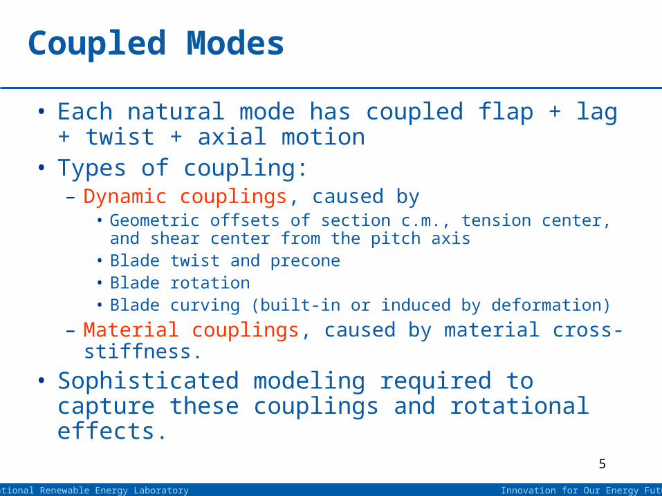
• Each natural mode has coupled flap + lag + twist + axial motion
• Types of coupling:– Dynamic couplings, caused by
• Geometric offsets of section c.m., tension center, and shear center from the pitch axis
• Blade twist and precone• Blade rotation• Blade curving (built-in or induced by deformation)
– Material couplings, caused by material cross-stiffness.
• Sophisticated modeling required to capture these couplings and rotational effects.
Coupled Modes

6
Innovation for Our Energy Future National Renewable Energy Laboratory
• Tower configurations that BModes can model:– Land-based tower
• with tower head inertia
• with or without tension-wires support
– Offshore tower: supported by• floating-platform
– Barge + mooring lines– spar-buoy + mooring lines– TLP (tension-legs platform)
• monopile (no multi-pod supports)
BModes Usage: for Towers

7
Innovation for Our Energy Future National Renewable Energy Laboratory
• Given:– Elastic tower distributed geometric & structural properties– Tower-head inertias and c.m. offsets from tower top– Tension-wires stiffness and geometric layout– Floating-platform hydrodynamic & hydrostatic properties + mooring
lines 6x6 stiffness matrix– Monopile foundation elastic properties– Hydrodynamic added mass on submerged part of the elastic tower
• Computes:– Modal frequencies & coupled modes
(coupled fore-aft + side-side + twist + axial motion + platform motions)
BModes Usage for Towers (cont’d)
8
Innovation for Our Energy Future National Renewable Energy Laboratory
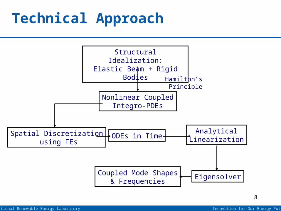
Technical Approach
Structural Idealization:Elastic Beam + Rigid Bodies
Nonlinear CoupledIntegro-PDEs
Spatial Discretization using FEs
ODEs in TimeAnalytical
Linearization
Coupled Mode Shapes& Frequencies
Eigensolver
Hamilton’s Principle

9
Innovation for Our Energy Future National Renewable Energy Laboratory
• Uses 15-dof finite element with two external and three internal nodes
Salient Features of BModes
1
1
1
1
1
1
u
v
v
w
w
4
2
2
2
2
3
u
v
v
w
w
2u 3u2
Distributed stiffness
Distributed hydrodynamic mass
1
1
1
1
1
1
u
v
v
w
w
4
2
2
2
2
3
u
v
v
w
w
2u 3u2
Distributed stiffness
Distributed hydrodynamic mass

10
Innovation for Our Energy Future National Renewable Energy Laboratory
• Accurately handles rotational effects (centrifugal, Coriolis, tennis-racket, etc)
• Uses quasi-coordinates: give rise to spatial-integral terms• Uses specialized finite-element assembly • Provides for precone & pitch control setting• Allows arbitrary distributed beam properties• Has potential to handle a complex range of boundary
conditions• Uses analytically linearized equations accurate and
computationally fast
Salient Features of BModes (cont’d)

11
Innovation for Our Energy Future National Renewable Energy Laboratory
• Straight Euler-Bernoulli beam
• Isotropic properties (no cross-stiffnesses)
• Rotary inertia effects included, but shear deformation effects ignored.
• Moderate deformations, but small strains.
• For tower modal analysis, tower head (nacelle+rotor) and platform are modeled as 6-dof rigid-body inertias.
• Foundation (soil) is modeled as a distributed spring.
Assumptions & Limitations

12
Innovation for Our Energy Future National Renewable Energy Laboratory
BModes Verification
• For blades:BModes verified extensively using models ranging from a rotating string to realistic blades.
• For towers:Verification in progress.

13
Innovation for Our Energy Future National Renewable Energy Laboratory
Sample Verification Resultsfor
Blades

14
Innovation for Our Energy Future National Renewable Energy Laboratory
Cantilevered Uniform Blade (Nonrotating)Comparison of Modal Frequencies
Mode Number
Flap Frequencies (Hz)
Lag Frequencies(Hz)
Torsion Frequencies (Hz)
Analytical BModes Analytical BModes Analytical BModes
1 0.560 0.560 1.119 1.119 2.572 2.572
2 3.507 3.507 7.014 7.014 7.717 7.717
3 9.819 9.819 19.639 19.639 12.862 12.862
4 19.242 19.242 38.484 38.484 18.007 18.007
5 31.809 31.809 63.617 63.618 23.152 23.152

15
Innovation for Our Energy Future National Renewable Energy Laboratory
Spinning Uniform CableComparison of Flap Modal Frequencies
CableSpin Rate
(rad/sec)
First Flap Frequency (rad/sec)
Second Flap Frequency (rad/sec)
Third Flap Frequency (rad/sec)
Analytical BModes Analytical BModes Analytical BModes
0 0.0 0.00 0.00 0.00 0.00 0.00
2 2.0 2.00 4.90 4.91 7.75 7.76
6 6.0 6.01 14.70 14.72 23.24 23.27
10 10.0 10.02 24.49 24.53 38.73 38.79
15 15.0 15.03 36.74 36.80 58.09 58.18
20 20.0 20.04 48.99 49.07 77.46 77.58
25 25.0 25.04 61.24 61.33 96.82 96.97
30 30.0 30.05 73.48 73.60 116.19 116.37

16
Innovation for Our Energy Future National Renewable Energy Laboratory
Spinning Uniform CableComparison of Lag Modal Frequencies
Cable Spin Rate,
(rad/sec)
First Lag Frequency (rad/sec)
Second Lag Frequency (rad/sec)
Third Lag Frequency (rad/sec)
Analytical BModes Analytical BModes Analytical BModes
0 0.0 0.00 0.00 0.00 0.00 0.00
2 0.0 0.02 4.47 4.48 7.48 7.50
6 0.0 0.04 13.42 13.44 22.45 22.49
10 0.0 0.06 22.36 22.40 37.42 37.48
15 0.0 0.09 33.54 33.60 56.12 56.22
20 0.0 0.12 44.72 44.80 74.83 74.96
25 0.0 0.15 55.90 56.01 93.54 93.69
30 0.0 0.18 67.08 67.21 112.25 112.43

17
Innovation for Our Energy Future National Renewable Energy Laboratory
Spinning Uniform CableComparison of Bending Mode Shapes
-0.6
-0.4
-0.2
0
0.2
0.4
0.6
0.8
1
0 0.1 0.2 0.3 0.4 0.5 0.6 0.7 0.8 0.9 1
Span Locaion (x/L)
Mo
da
l D
isp
lac
em
en
t(F
lap
or
La
g)
Mode 1
Mode 3
Mode 2
= 6 rad/sec
BModes Analytical

18
Innovation for Our Energy Future National Renewable Energy Laboratory
Rotating Uniform Blade Comparison of Flap Frequencies
Blade Spin Rate,
(rad/sec)
First Flap Frequency (rad/sec)
Second Flap Frequency (rad/sec)
Third Flap Frequency (rad/sec)
Analytical BModes Analytical BModes Analytical BModes
0 3.516 3.516 22.035 22.034 61.697 61.696
1 3.682 3.682 22.181 22.181 61.842 61.841
2 4.137 4.137 22.615 22.615 62.273 62.272
3 4.797 4.797 23.320 23.320 62.985 62.984
4 5.585 5.585 24.273 24.273 63.967 63.966
5 6.450 6.450 25.446 25.446 65.205 65.204
6 7.360 7.360 26.809 26.809 66.684 66.683
7 8.300 8.300 28.334 28.334 68.386 68.385
8 9.257 9.257 29.995 29.995 70.293 70.293
9 10.226 10.226 31.771 31.770 72.387 72.386
10 11.202 11.202 33.640 33.640 74.649 74.649
11 12.184 12.184 35.589 35.589 77.064 77.063
12 13.170 13.170 37.603 37.603 79.615 79.614

19
Innovation for Our Energy Future National Renewable Energy Laboratory
Rotating Uniform Blade Comparison of Lag Frequencies
Blade Spin Rate,
(rad/sec)
First Lag Frequency (rad/sec)
Second Lag Frequency (rad/sec)
Third Lag Frequency (rad/sec)
Analysis BModes Analysis BModes Analysis BModes
0 11.118 11.118 69.529 69.678 194.455 195.101
2 11.153 11.153 69.685 69.835 194.624 195.274
4 11.255 11.255 70.153 70.304 195.143 195.791
6 11.421 11.421 70.927 71.079 196.000 196.650
8 11.642 11.642 71.996 72.150 197.187 197.845
10 11.911 11.911 73.348 73.505 198.712 199.370
12 12.219 12.219 74.967 75.127 200.547 201.216
15 12.735 12.735 77.858 78.025 203.887 204.565
21 13.877 13.877 85.083 85.266 212.501 213.210
25 14.668 14.668 90.774 90.968 219.539 220.275
30 15.652 15.652 98.648 98.859 229.609 230.379

20
Innovation for Our Energy Future National Renewable Energy Laboratory
WindPact 1.5 MW Turbine Blade Comparison of Modal Frequencies
Blade Spin Rate,
(rad/sec)
First Modal Frequency (Hz)
Second Modal Frequency (Hz)
Third Modal Frequency (Hz)
RCAS BModes RCAS BModes RCAS BModes
0 1.229 1.228 1.875 1.873 3.662 3.657
2 1.300 1.298 1.889 1.887 3.736 3.732
5 1.608 1.606 1.959 1.957 4.104 4.100
10 2.146 2.144 2.384 2.381 5.159 5.154
15 2.429 2.426 3.209 3.205 6.366 6.359
20 2.732 2.730 4.055 4.051 7.237 7.229
25 3.044 3.041 4.905 4.900 7.339 7.331
35 3.669 3.665 4.546 4.541 6.612 6.605
50 4.591 4.586 9.150 9.140 12.389 12.375

21
Innovation for Our Energy Future National Renewable Energy Laboratory
WindPact 1.5 MW Turbine Blade Comparison of 1st Modes
-0.02
0
0.02
0.04
0.06
0.08
0.1
0.12
0 0.2 0.4 0.6 0.8 1
Span Locaion (x/L)
FlapTorsion
Lag
1st Coupled Mode= 50 rad/sec
BModes RCAS
-0.02
0
0.02
0.04
0.06
0.08
0.1
0.12
0 0.2 0.4 0.6 0.8 1
Span Locaion (x/L)
Mo
dal
Dis
pla
cem
ent
Flap
Torsion
Lag
1st Coupled Mode= 2 rad/sec
BModes RCAS

22
Innovation for Our Energy Future National Renewable Energy Laboratory
WindPact 1.5 MW Turbine Blade Comparison of 2nd Modes
-0.15
-0.1
-0.05
0
0.05
0.1
0.15
0.2
0.25
0 0.2 0.4 0.6 0.8 1
Span Locaion (x/L)
Flap
Torsion
Lag
2nd Coupled Mode= 50 rad/sec
BModes RCAS
-0.15
-0.1
-0.05
0
0.05
0.1
0.15
0.2
0.25
0 0.2 0.4 0.6 0.8 1
Span Locaion (x/L)
Mo
dal
Dis
pla
cem
ent
Flap
Torsion
Lag
2nd Coupled Mode= 2 rad/sec
BModes RCAS

23
Innovation for Our Energy Future National Renewable Energy Laboratory
WindPact 1.5 MW Turbine Blade Comparison of 3rd Modes
-0.05
-0.025
0
0.025
0.05
0.075
0.1
0 0.2 0.4 0.6 0.8 1
Span Locaion (x/L)
Mo
dal
Dis
pla
cem
ent
FlapTorsion
Lag
3rd Coupled Mode= 2 rad/sec
BModes RCAS
-0.15
-0.1
-0.05
0
0.05
0.1
0.15
0.2
0.25
0 0.2 0.4 0.6 0.8 1
Span Locaion (x/L)
Flap
Torsion
Lag
3rd Coupled Mode= 50 rad/sec
BModes RCAS

24
Innovation for Our Energy Future National Renewable Energy Laboratory
• Complete verification of tower modal analysis.
• Release BModes-3 along with new user’s manual.
• Integrate BModes with CFD (collaboration with NASA).
• Provide for composites.
• Integrate with FAST.
• Extend formulation for curved blades
• Introduce Timoshenko beam element.
Future Plans

25
Operated for the U.S. Department of Energy Office of Energy Efficiency and Renewable Energy by Midwest Research Institute • Battelle
Questions?