innovation intelligence ® section 6 meshing in simlab
TRANSCRIPT

Innovation Intelligence®
Section 6Meshing in SimLab

Copyright © 2012 Altair Engineering, Inc. Proprietary and Confidential. All rights reserved.
Meshing Process
Import CAD model
Open Meshing Application
Surface mesh the CAD model
Check surface mesh Water tight check Element overlap check Element quality check
Fix errors in surface mesh Manual cleanup Automated cleanup
Volume mesh
Verify element quality

Copyright © 2012 Altair Engineering, Inc. Proprietary and Confidential. All rights reserved.
Step 1: Import the CAD model
When importing the model, the user will be prompted for
the unit selection as per their need.
There are options to import solid bodies, sheet bodies and
wire bodies.
The Parasolid model can be imported as facets.
The overlapping faces of the Parasolid parts can be
imprinted during import.

Copyright © 2012 Altair Engineering, Inc. Proprietary and Confidential. All rights reserved.
Step 1: Import the CAD model
Copyright © 2012 Altair Engineering, Inc. Proprietary and Confidential. All rights reserved.
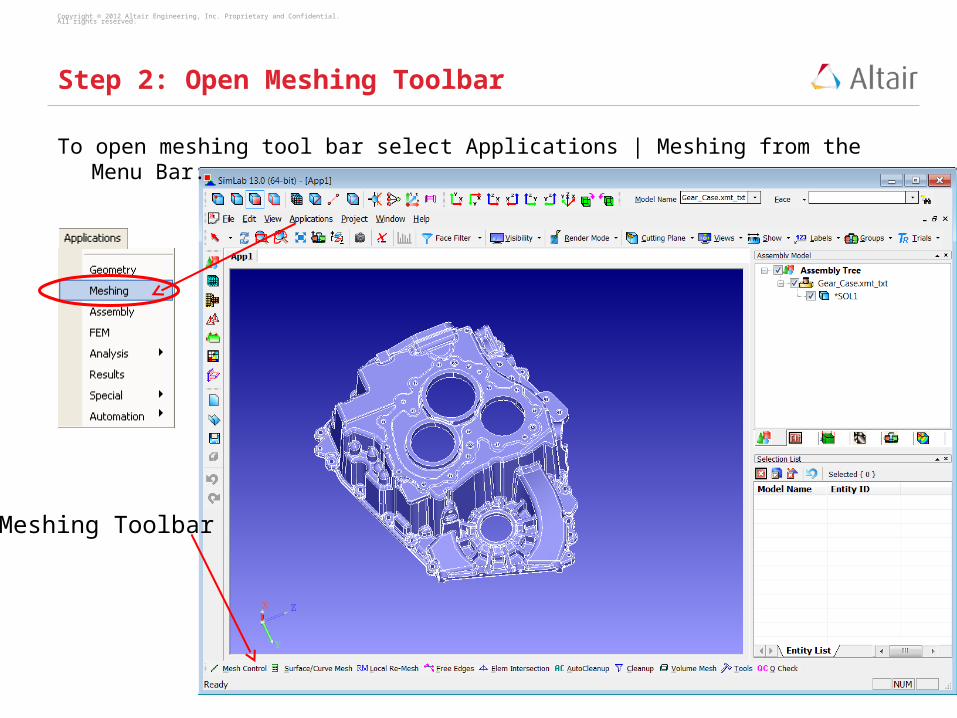
Step 2: Open Meshing Toolbar
To open meshing tool bar select Applications | Meshing from the Menu Bar.
Meshing Toolbar

Copyright © 2012 Altair Engineering, Inc. Proprietary and Confidential. All rights reserved.
Step 3: Surface Mesh
Select “Surface/Curve Mesh” in the Meshing Tool Bar to open the Surface Mesh dialog
box.
Select Entities ( Body or Face).
Enter the desired mesh parameters and select OK.

Copyright © 2012 Altair Engineering, Inc. Proprietary and Confidential. All rights reserved.
The Body is surface meshed.
A new model is created with the meshed
body.
Step 3: Surface Mesh
Copyright © 2012 Altair Engineering, Inc. Proprietary and Confidential. All rights reserved.
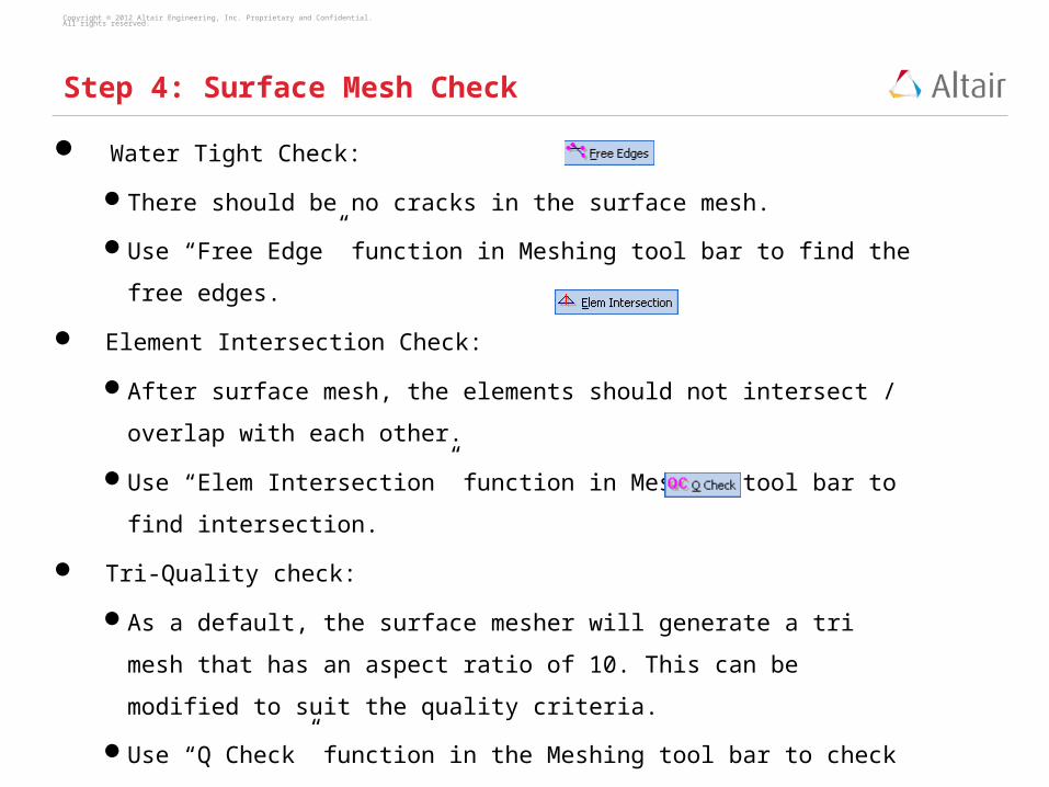
Water Tight Check:
There should be no cracks in the surface mesh.
Use “Free Edge” function in Meshing tool bar to find the free edges.
Element Intersection Check:
After surface mesh, the elements should not intersect / overlap with each
other.
Use “Elem Intersection” function in Meshing tool bar to find intersection.
Tri-Quality check:
As a default, the surface mesher will generate a tri mesh that has an aspect
ratio of 10. This can be modified to suit the quality criteria.
Use “Q Check” function in the Meshing tool bar to check the quality of the Tri
elements.
Step 4: Surface Mesh Check

Copyright © 2012 Altair Engineering, Inc. Proprietary and Confidential. All rights reserved.
If any of the check fails, use cleanup tool to clean up the mesh. Clean up can
be done using both Automated tools and Manual tools.
Automated Cleanup
Fill Crack – Used to fill the cracks in the body.
Fill Holes – Used to fill holes in the body.
Auto QuadClean – Used to clean up the Quad mesh.
Step 5: Surface Mesh Cleanup

Copyright © 2012 Altair Engineering, Inc. Proprietary and Confidential. All rights reserved.
Manual Cleanup
Create Element
Split
Swap
Collapse
Equivalence
Combine 2Tris to Quad
Split Quad to Tris
Delete Element
Update Layers
Step 5: Surface Mesh Cleanup

Copyright © 2012 Altair Engineering, Inc. Proprietary and Confidential. All rights reserved.
Select “Volume Mesh” from the Meshing tool bar to open
the volume mesh dialog box.
Specify the desired element type, average element size
and element quality parameters.
Select OK to generate the volume mesh.
Step 6: Volume Mesh

Copyright © 2012 Altair Engineering, Inc. Proprietary and Confidential. All rights reserved.
Step 6: Volume Mesh

Copyright © 2012 Altair Engineering, Inc. Proprietary and Confidential. All rights reserved.
Right click on the Volume mesh body in the tree view and select Properties to
show details of the meshed body.
Step 6: Volume Mesh

Copyright © 2012 Altair Engineering, Inc. Proprietary and Confidential. All rights reserved.
Use Q Check tools in Mesh toolbar to verify element quality. The elements
that fails for particular quality criteria can be found, displayed and cleaned
automatically.
Step 7: Check Quality