innovative approaches to mid-rise wood frame construction · 1 1 1 mid-rise 2.0 innovative...
TRANSCRIPT

111
Mid-Rise 2.0Innovative Approaches to Mid-Rise Wood Frame Construction
A CAse study
the HeightsVancouver, BC
King edward VillaVancouver, BC
VirtuosoVancouver, BC

2
Introduction .................................................................................................................. 3Low Energy Construction in the City of Vancouver ............................................................. 5
ThE hEIghTs ............................................................................................................... 6Design Strategies for Passive House Performance ................................................. 7Making a Business Case ...................................................................................... 7Passive House Performance Using Standard Construction Techniques .................... 8
KIng Edward VILLa ................................................................................................. 12A Low Energy Solution ........................................................................................ 13An Innovative Structural System .......................................................................... 14The Advantages of Prefabrication ........................................................................ 15
Changes to the national Building Code of Canada ............................................................ 17
VIrTuoso .................................................................................................................. 18A Hybrid Structure .............................................................................................. 19A Virtual Model .................................................................................................. 22
Carbon Charts ............................................................................................................... 23Conclusion .................................................................................................................... 23
Project Credits ................................................................................................. back cover
tABLe OF CONteNts
Photo credits:
1.1 & front cover .....Cornerstone Architecture
1.2 & front cover...Derek Leppar Photography
1.3 & front cover ............ Adera Development
Corporation
2.1 ......................Cornerstone Architecture
2.2 ......................Cornerstone Architecture
2.3 ......................Cornerstone Architecture
2.4 ......................Cornerstone Architecture
2.5 ......................Cornerstone Architecture
2.6 ......................Cornerstone Architecture
2.7 ......................Cornerstone Architecture
2.8 ......................Cornerstone Architecture
2.9 ......................Cornerstone Architecture
2.10 ......................Cornerstone Architecture
2.11 ......................Cornerstone Architecture
2.12 ...................... Cornerstone Architecture
3.1 ......................................GBL Architects
3.2 .............. Take Off Eh! Aerial and Artistic
Photography
3.3 ....................Derek Leppar Photography
3.4 ......................................GBL Architects
3.5 .................... Performance Construction
3.6 ..........................................Jim Taggart
3.7 .................... Performance Construction
3.8 .................... Performance Construction
3.9 .................... Performance Construction
3.10 .................... Performance Construction
3.11 ......................................GBL Architects
3.12 .................... Performance Construction
4.1 ..................Rositch Hemphill Architects
4.2 Wicke Herest Maver Structural Engineers
4.3 ........... Adera Development Corporation
4.4 ........... Adera Development Corporation
4.5 Wicke Herest Maver Structural Engineers
4.6 Wicke Herest Maver Structural Engineers
4.7 Wicke Herest Maver Structural Engineers
4.8 Wicke Herest Maver Structural Engineers
4.9 Wicke Herest Maver Structural Engineers
4.10 ........... Adera Development Corporation
4.11 ........... Adera Development Corporation
5.1 ........... Adera Development Corporation
Back cover ... Adera Development CorporationCredit: Adera Development Corporation
INtROduCtION
3
Further revisions to the 2015 NBC to be introduced in
British Columbia in 2017 will expand the permissible
use of six-storey wood construction from multi-family
residential (Group C) occupancies to business and
personal services occupancies in Group D.
Prior to “modern” building codes, such buildings
were often constructed using heavy timber post-and-
beam systems, with solid timber floors. However, with
the advent of new mass timber panel products, the
opportunity has arisen for developers and design teams
to explore new forms of wood construction, including
hybrid mass timber/light wood frame construction.
In response to these new market conditions, traditional
wood frame construction techniques and project
delivery methods have been modified or adapted to
achieve greater efficiency, economy and performance.
This case study looks at three different projects in the
Vancouver area, similar in having a predominantly
multi-family residential program, but differing
considerably in their approach to design, construction
details and project delivery.
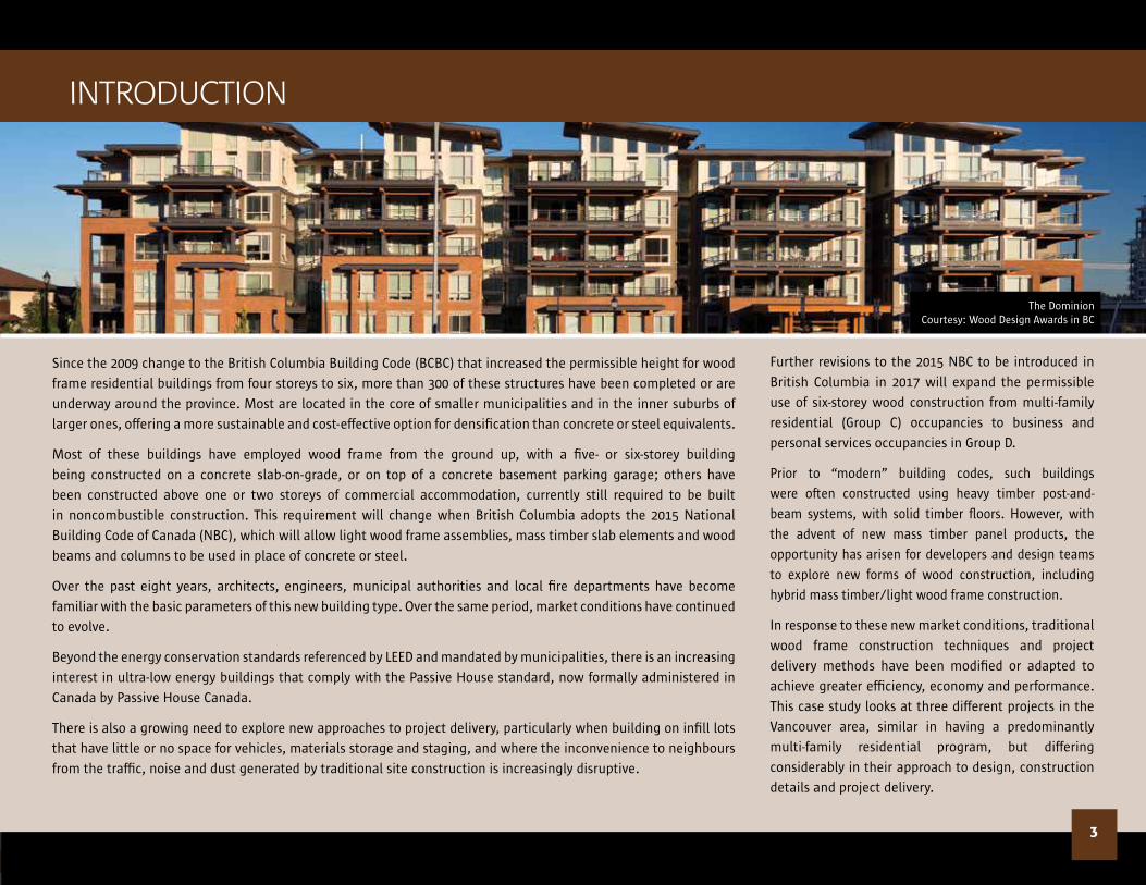
Since the 2009 change to the British Columbia Building Code (BCBC) that increased the permissible height for wood
frame residential buildings from four storeys to six, more than 300 of these structures have been completed or are
underway around the province. Most are located in the core of smaller municipalities and in the inner suburbs of
larger ones, offering a more sustainable and cost-effective option for densification than concrete or steel equivalents.
Most of these buildings have employed wood frame from the ground up, with a five- or six-storey building
being constructed on a concrete slab-on-grade, or on top of a concrete basement parking garage; others have
been constructed above one or two storeys of commercial accommodation, currently still required to be built
in noncombustible construction. This requirement will change when British Columbia adopts the 2015 National
Building Code of Canada (NBC), which will allow light wood frame assemblies, mass timber slab elements and wood
beams and columns to be used in place of concrete or steel.
Over the past eight years, architects, engineers, municipal authorities and local fire departments have become
familiar with the basic parameters of this new building type. Over the same period, market conditions have continued
to evolve.
Beyond the energy conservation standards referenced by LEED and mandated by municipalities, there is an increasing
interest in ultra-low energy buildings that comply with the Passive House standard, now formally administered in
Canada by Passive House Canada.
There is also a growing need to explore new approaches to project delivery, particularly when building on infill lots
that have little or no space for vehicles, materials storage and staging, and where the inconvenience to neighbours
from the traffic, noise and dust generated by traditional site construction is increasingly disruptive.
The Dominion Courtesy: Wood Design Awards in BC

4
ThE hEIghTs is pursuing Passive House certification,
with high levels of thermal insulation and superior
airtightness achieved in a building that in most other
respects relies on standard light wood frame construction
techniques.
At KIng Edward VILLa, off-site construction has
been successfully incorporated into traditional contractual
arrangements, and has delivered benefits in terms of
precision, speed of erection and coordination between
sub-trades.
tHe HeIGHtsVANCOuVeR, BC
KING edWARd VILLAVANCOuVeR, BC
Fig. 1.1: The Heights
Fig. 1.2: King Edward Villa

VIRtuOsOWesBROOK VILLAGe, VANCOuVeR, BC
5
In the VIrTuoso project at the University of British
Columbia, mass timber and light wood frame elements have
been used in combination, in an exploration of the hybrid
construction that may prove most suitable for the new
generation of commercial buildings that will undoubtedly
emerge with the upcoming changes to the BCBC.
In order to connect to the City’s district heating systems, buildings must have hydronic heat.
Such systems rely on delivering hot water through a network of pipes, and thus have a high
initial capital cost and relatively high operating and maintenance costs. For a building that will
be sold on completion, these costs are passed on to individual condominium owners and their
strata corporations, and may thus be a justifiable investment for developers in exchange for
the LEED credits they accrue under the present regulations.
However, for rental properties the priorities are different. Under the City’s Rental 100 program,
developers benefit from a waiver of community amenity charges and a reduced requirement
for off-street parking, but in return must commit to operating and maintaining the project as a
rental building for the full duration of a 60-year lease agreement. Under these circumstances,
developers prefer to heat the building with electricity, as it is currently less expensive than gas.
Low energy Construction in the City of VancouverIn the summer of 2016, the City of Vancouver initiated a process to eliminate the requirement
for new developments to meet the LEED Gold standard for energy performance, and instead
encourage the move toward net zero emission buildings.
City Council directed staff to enact policies “to build all new City-owned and Vancouver
Affordable Housing Agency (VAHA) projects to the Passive House standard or alternate zero
emission building standard”. This policy will be applicable for all City-owned and VAHA building
projects by 2018. The new rezoning policy will incorporate requirements for calculating and
reporting embodied emissions for proposed rezoning projects.
In the meantime, the City’s Sustainability Group is tasked with removing barriers to innovation
that might be present in the zoning or building bylaws, and to assist proponents in the
realization of projects that support the City’s carbon neutral goal for operating energy. Such
accommodations may include relaxing side and rear yard setbacks to permit thicker, more
highly insulated walls to be built without compromising the permissible floor space ratio; or
waiving the requirement to have their project connect to a district energy plant.
Fig. 1.3: Virtuoso

Residential
Residential
Residential
Residential
Residential
Commercial
Parkade
Residential
Residential
Residential
Residential
Residential
Commercial
Parkade
Ramp
Roof Deck
Elevator Stair
tHe HeIGHts
6
Beginning construction in the summer of 2016, The Heights
is a six-storey mixed-use building located on the corner
of Skeena and East Hastings Streets, a rapidly developing
area in Vancouver’s northeast quadrant. The ground level
commercial space and the single level of underground
parking are constructed in concrete, with 85 apartments
occupying the rear of the ground floor and the five storeys of
wood frame construction above (Fig. 2.1).
The project was rezoned from existing C-2 commercial
under the City of Vancouver Rental 100 program (see: Low
Energy Construction in the City of Vancouver - on previous
page). Cornerstone Architecture, whose track record in high
performance buildings dates back 35 years to the first BC
Hydro PowerSmart townhouse development, approached the
City for permission to create a Passive House project.
Fig. 2.1: Schematic section
Credit: Cornerstone Architecture

design strategies for Passive House Performance Making a Business Case
7
Scott Kennedy had to first convince his client that the
Passive House approach made sense from a business
perspective. He argued that a conventional hydronic
heating system would have a capital cost of approximately
$450,000 and that maintenance and repairs over the
60-year life of the building had a net present value
of $150,000. If this money could instead be spent on
additional insulation, higher performance windows,
comprehensive sealing of the building to achieve the
necessary airtightness, and electric baseboard radiators,
the net cost would be the same. The advantage would
accrue to the developer in the form of greatly reduced
operating costs.
Passive House buildings, which consume 80-90 per cent less energy for heating and cooling than conventional buildings, require
a radically different approach to design.
The most important strategies for Passive house and other ultra-low energy buildings are:
• correct orientation, sizing and shading of windows to optimize passive solar heating;
• a super-insulated building envelope with minimal thermal bridging;
• airtightness to reduce heat loss through air leakage;
• the reduction of ventilation rates to the minimum required to maintain healthy indoor air quality; and
• the recapture of heat from exhaust air using heat recovery ventilation.
The cumulative effect of these strategies is to reduce the building’s energy demand to such an extent that internal energy sources
(such as people and heat loss from hot water tanks and other systems) becomes significant, and may provide as much as 40
per cent of required input heating energy. Much of the remainder can be supplied most of the time using passive solar energy
from carefully sized and appropriately shaded south-facing windows. With Passive House construction, conventional mechanical
systems can be much smaller and much simpler than in traditionally designed buildings.
Despite this different approach to design, Scott Kennedy of Cornerstone Architecture was determined to demonstrate that the
Passive House standard could be achieved using traditional construction methods. His aim was to design the building in such a
way that the majority of the trades would hardly notice any difference in their work practices. In collaboration with Doug Wilson
of Peak Construction, Kennedy developed details that would minimize uncertainty, risk and additional cost.

8
Passive House Performance using standard Construction techniques
Cornerstone designed the building with a conventional
nominal 2x6 wood stud exterior wall, sheathed in plywood
and supporting a rain screen system of brick veneer. These
walls contain no services (these are contained within
a secondary service wall - see below), facilitating the
installation of insulation (Fig. 2.2). The exterior walls,
interior load-bearing and shear walls were prefabricated by
a specialist framing subcontractor. The use of kiln-dried top
and bottom plates for the bearing walls, in combination with
wood I-joists for the floors, minimized the amount of cross-
grain material in the vertical section of the building and so
minimized shrinkage.
Inboard of the 2x6 exterior wall, and separated from it by a two-
inch gap, is a secondary nominal 2x4 wood stud service wall.
This wall, together with some non-load-bearing interior walls
at the lowest level, were framed by the general contractor’s
workforce on site, which was less expensive than using a
specialist crew. The service walls were built after installation
of two inches of expanded polystyrene rigid insulation on the
interior face of the exterior wall. Factory finished with a polymer
coating, the insulation acts as both a vapour and air barrier
when appropriately sealed. Sealing takes the form of proprietary
tapes at joints, and caulking where necessary. To accommodate
the insulation and service wall, interior partitions were held
back 5.5 inches from the exterior wall (Fig. 2.3).
Fig. 2.3: Installation of rigid air barrier
26
24
26
26
24
24
EXTERIOR
COLD
SUITE
WARM
2 8
26
2 8
2 8
2 8
2 8
2 8
SUITE
WARM
FACE OF
PLYWOOD
FACE OF
FRAMING
FA
CE
OF
FR
AM
ING
FA
CE
OF
FR
AM
ING
FA
CE
OF
FR
AM
ING
Plan view: Window / Interior wall conection
Scale: 1 1/2" = 1'-0"
26
26
SUITEWARM
28
2 6
2 4 24
EXT. DECKCOLD
SUITEWARM
2 8
26
2 8
2 8
2 8
2 8
2 8
2 4
FACE OF
PLYWOOD
FACE OF
FRAMING
FA
CE
OF
PLY
WO
OD
FA
CE
OF
FR
AM
ING
Plan view: Exterior wall corner
Scale: 1 1/2" = 1'-0"
Fig. 2.2: exterior wall plan view
9
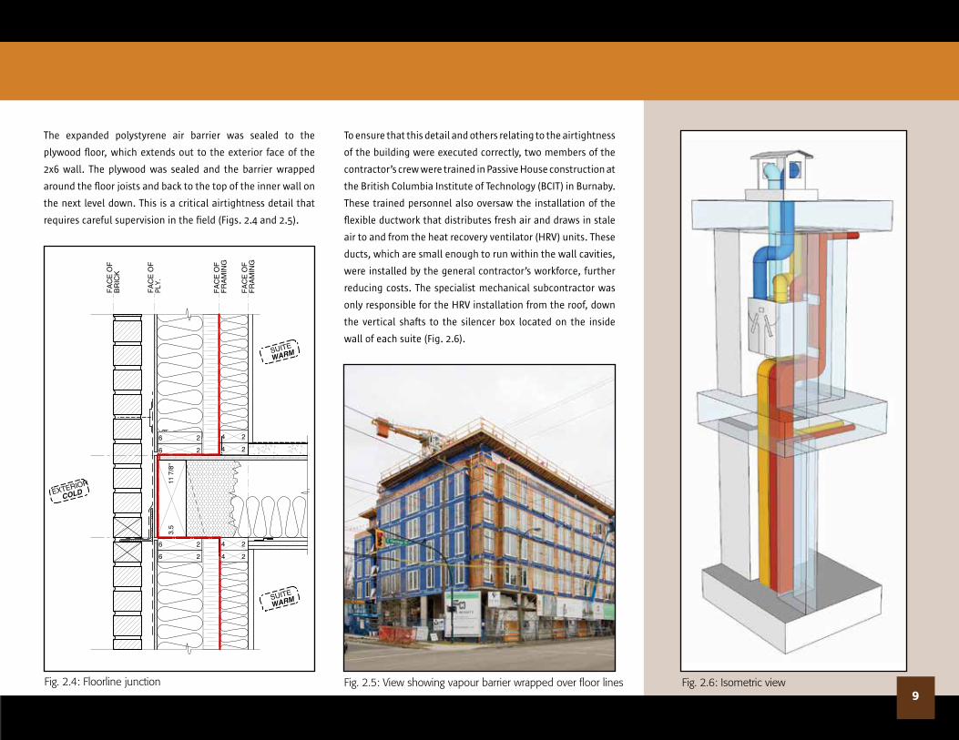
The expanded polystyrene air barrier was sealed to the
plywood floor, which extends out to the exterior face of the
2x6 wall. The plywood was sealed and the barrier wrapped
around the floor joists and back to the top of the inner wall on
the next level down. This is a critical airtightness detail that
requires careful supervision in the field (Figs. 2.4 and 2.5).
To ensure that this detail and others relating to the airtightness
of the building were executed correctly, two members of the
contractor’s crew were trained in Passive House construction at
the British Columbia Institute of Technology (BCIT) in Burnaby.
These trained personnel also oversaw the installation of the
flexible ductwork that distributes fresh air and draws in stale
air to and from the heat recovery ventilator (HRV) units. These
ducts, which are small enough to run within the wall cavities,
were installed by the general contractor’s workforce, further
reducing costs. The specialist mechanical subcontractor was
only responsible for the HRV installation from the roof, down
the vertical shafts to the silencer box located on the inside
wall of each suite (Fig. 2.6).
Fig. 2.4: Floorline junction Fig. 2.5: View showing vapour barrier wrapped over floor lines Fig. 2.6: Isometric view
24
24
26 24
24
26
3.5
11 7
/8"
26
26
FA
CE
OF
FR
AM
ING
FA
CE
OF
FR
AM
ING
FA
CE
OF
PLY.
FA
CE
OF
BR
ICK
SUITE
WARM
EXTERIOR
COLD
SUITE
WARM
Section: Floorline - Frame
Scale: 1 1/2" = 1'-0"
2426
SUITE
WARM
EXTERIOR
COLD
24
26
28
28
2426
FA
CE
OF
PLY
WO
OD
FA
CE
OF
FR
AM
ING
FA
CE
OF
CO
NC
RE
TE
FA
CE
OF
BR
ICK
FA
CE
OF
FR
AM
ING
SUITE
WARM
Section: Floorline - Concrete
Scale: 1 1/2" = 1'-0"

10
28
SUITE
WARM
24
26
26
24
2426AB
26
26
3 1
/2"
11 7
/8"
FA
CE
OF
FR
AM
ING
FA
CE
OF
FR
AM
ING
FA
CE
OF
PLY.
EXTERIOR
COLD
EXTERIOR
COLD
SUITE
WARM
Section: Aluminum Sunshade
Scale: 1 1/2" = 1'-0"
Fig. 2.7: sunshade attachment detail
21
0
21
0
FA
CE
OF
FR
AM
ING
FA
CE
OF
PLY
.
24
24
FA
CE
OF
PLY
.
23
26
28
26
26
26
SUITE
WARM
EXTERIOR
COLD
EXTERIOR
COLD
Section: Wall / Roof connection
Scale: 1 1/2" = 1'-0"
Fig. 2.8: Wall/roof junction
To eliminate thermal bridging, sunshades and balconies
were hung off the 2x6 exterior wall and the fasteners did not
penetrate the insulation, nor puncture the air barrier (Fig.
2.7). The interior service wall was also insulated, meaning
that the vapour barrier is in the centre of the wall, and
the drying out of any moisture that might become trapped
within the wall happens to either the interior or exterior,
depending on where it occurs. Some joist ends penetrate the
wall and were treated with spray polyurethane for vapour
control. The performance of the wall assembly was tested
using simulation software that modelled fluctuations in
temperature and humidity over the course of a year. The wall
met the requirements with respect to moisture control.
The roof also has significantly more insulation than a
conventional structure, with fibreglass batts between the
ceiling joists, and six inches of polyisocyanurate insulation
on top of six inches of sloped expanded polystyrene above
(Fig. 2.8). Modelling demonstrated that this assembly also
met the requirements for vapour control.
As is now common in mid-rise wood frame buildings that sit
on top of a concrete podium, the elevator shaft is constructed
in concrete on the retail/parking level, transitioning into nail-
laminated timber (NLT) where the wood frame construction
begins. This strategy eliminates the problem of differential
movement that can occur at junctions between dissimilar
materials (e.g. at elevator thresholds when a concrete shaft is
used in an otherwise all-wood building).

11
Rather than have the NLT elevator shaft (which begins at Level 2) built directly off the concrete slab, Kennedy proposed a parallel
strand lumber (PSL) beam be used at this point. The intention was to exploit the lower thermal conductivity of wood to reduce
thermal bridging (Fig. 2.9).
The careful attention to detailing and sealing for airtightness (Fig. 2.10) has resulted in a building envelope in which thermal
bridging has been completely eliminated (Figs. 2.11 and 2.12). With its careful attention to detail, The Heights has confirmed that
traditional wood frame construction techniques can successfully be applied to the new generation of high performance buildings.
Fig. 2.9: elevator shaft
Fig. 2.10: taping of vapour barrier at window
Fig. 2.12: thermal gradient at floorline junctionFig. 2.11: thermal gradient at window sill
1. NLT Elevator Shaft2. PSL Beam
1
2
KING edWARd VILLA
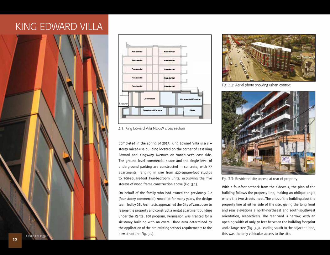
Completed in the spring of 2017, King Edward Villa is a six-
storey mixed-use building located on the corner of East King
Edward and Kingsway Avenues on Vancouver’s east side.
The ground level commercial space and the single level of
underground parking are constructed in concrete, with 77
apartments, ranging in size from 420-square-foot studios
to 700-square-foot two-bedroom units, occupying the five
storeys of wood frame construction above (Fig. 3.1).
On behalf of the family who had owned the previously C-2
(four-storey commercial) zoned lot for many years, the design
team led by GBL Architects approached the City of Vancouver to
rezone the property and construct a rental apartment building
under the Rental 100 program. Permission was granted for a
six-storey building with an overall floor area determined by
the application of the pre-existing setback requirements to the
new structure (Fig. 3.2).
12
Fig. 3.2: Aerial photo showing urban context
3.1: King edward Villa Ne-sW cross section
Fig. 3.3: Restricted site access at rear of property
Residential
Residential
Residential
Residential
Residential Residential
Residential
Residential
Residential
Residential
Commercial Commercial Parkade
LegendWarm
Cold
Residential Parkade Bikes
Credit: Jim taggart
With a four-foot setback from the sidewalk, the plan of the
building follows the property line, making an oblique angle
where the two streets meet. The ends of the building abut the
property line at either side of the site, giving the long front
and rear elevations a north-northeast and south-southwest
orientation, respectively. The rear yard is narrow, with an
opening width of only 40 feet between the building footprint
and a large tree (Fig. 3.3). Leading south to the adjacent lane,
this was the only vehicular access to the site.
Kingsway

A Low energy solution
The energy conservation strategies are the same in this
project as in 388 Skeena, but the implementation differs
in detail from the strict requirements of Passive House.
The super-insulated envelope was achieved by using
two nominal 2x4 wood stud walls with a one-inch space
between them. The exterior sheathing is plywood with a
vapour permeable (breathable) peel-and-stick membrane,
that also acts as an air barrier. The entire wall depth is
filled with two layers of spray-applied cellulose insulation
that achieves an R-value of 28. The cellulose eliminates
heat transfer by convection and, because it is hygroscopic
(able to absorb and release moisture), it provides added
insurance against interstitial condensation (Fig. 3.4).
The inside of the wall is lined with airtight drywall with
a vapour barrier paint on the interior face. Two layers of
5/8-inch fire-rated drywall were required to achieve
the one-hour fire resistance rating mandated by code,
and these were installed with gaskets around power
receptacles and other openings, and the edges were
sealed with fire-resistant caulking (Fig. 3.5).
Once a development permit had been received and building permit drawings were in process, the project was let as a construction
management contract. Up to this point, it was assumed that the building would be constructed using conventional nominal 2x6
wood framed exterior walls to meet the energy requirements of ASHRAE 90.1 and achieve a LEED Gold certification as mandated
by the City of Vancouver.
The contract was awarded to Performance Construction, who persuaded the developer to consider a low energy option based on
Passive design principles, using a similar business case to that described previously for The Heights.
13Fig. 3.4: Panel exterior wall at wood floor
Fig. 3.5: the edges of the drywall were caulked to meet fire and acoustic requirements

Because the floor structure runs parallel to the long
front and rear exterior walls (see discussion of structure
following), the only component that penetrates the
insulation layer is the plywood flooring. Windows and
doors are steel-reinforced vinyl “tilt-and-turn” units,
with low-E double glazing. The steel reinforcement
enables larger units to be used (Fig. 3.6) and gives the
suites a bright and open feeling. The average window-
to-wall ratio is approximately 32 per cent, but feels
higher because the two end walls of the building are
fire-resistance-rated walls with no window openings.
The drywall was installed before the gypsum concrete
floor screed was poured. This increases the airtightness
between inside and outside and also between suites.
Baseboards were glued in place.
The air change rate is controlled by a pair of HRVs
installed in each suite. The mechanical HRV systems for
each suite are self-contained, and operate continuously
at low speed (50 CFM) with a timed fan boost override (100
CFM) when required in the bathrooms. This configuration
differs from that used at The Heights where one rooftop
HRV serves a vertical stack of five suites.
14
The five-storey residential portion of the building is
constructed on top of a cast-in-place concrete basement
parking garage and ground floor commercial space. Elevator
and stair shafts in this area are also concrete, but everything
above the ground floor (with the exception of the non-load-
bearing fire-resistance-rated walls at each end of the building
(Fig. 3.7) is constructed in wood.
All these components were prefabricated by Mitsui Homes,
including the 2x6 NLT panels used for the elevator shaft
(Fig. 3.8); the innovative parallel chord floor trusses used
throughout the building; the non-load-bearing exterior walls;
the load-bearing shear and non-load-bearing interior walls;
and the triangular roof trusses (Fig. 3.9).
Of these components, the 12-inch-deep parallel chord floor
trusses are the most ingenious. Running parallel to the
exterior walls between interior load-bearing walls, their open
webs permit all the main mechanical and electrical services to
be run horizontally throughout each suite, with vertical drops
only where needed for HRV grilles, light switches, plugs, etc.
This made the installation of the mechanical and electrical
services easier and hence quicker than the traditional method
where piping and wiring must be threaded through rough
openings drilled or cut through studs and plates (Fig. 3.10).
Another advantage of the floor trusses was established
through a load path analysis performed by Mitsui Homes.
The analysis determined that the trusses could be hung from
their top chords only, enabling the drywall finish on party
walls to be notched around them, but otherwise taken up
to the underside of the floor above. This simplified the fire
separation between suites, with intumescent caulking used
to seal the joints, and mineral wool insulation used in the
ceiling cavities (refer back to Fig. 3.5).
Demising walls between suites, as well as other load-bearing
walls, were constructed using a double-wall system as
described above for the exterior walls. On the southwest side
of the building, these walls are topped with a 12-inch-deep
PSL beam that cantilevers approximately five feet beyond the
exterior wall to support the balconies (Fig. 3.11). Spanning
between the PSL beams are wood I-joists. This detail means
that, rather than a series of header joists penetrating the
building envelope to support the balconies, only the PSL
beams project, significantly reducing thermal bridging. The
deep balconies act as shading devices, keeping the summer
sun from striking the windows of the units below.
An Innovative structural system
Fig. 3.6: Façade detail

15
the Advantages of Prefabrication
From the architectural and structural drawings, Mitsui
Homes created a 3-D model that identified each individual
wall panel and truss, giving it specific attributes and a
unique position within the model. These elements were
also referenced to datum points that enabled each frame
that would (for example) be superimposed one on top of
the other on successive floors to be laid out and fabricated
with precisely the same stud positions and spacing.
Coordinated at the design stage with mechanical, electrical
and structural drawings, this meant that the vertical drops
for plumbing pipes, electrical conduits, tie-down anchors,
etc. could all be continuous. All that was needed was a
hole of the appropriate size to be drilled through the sill
and header plates and the plywood flooring to create a
perfectly aligned vertical drop (Fig. 3.12). Fig. 3.7: Concrete masonry fire-resistance-rated wall
Fig. 3.9: Construction of roof
Fig. 3.8: Installation of NLt elevator shaft Fig. 3.10: Parallel chord trusses enable services to be run within the depth of the floor
Fig. 3.12: the precision of the prefabricated frame walls enabled vertical services to be installed easily

16
Fig. 3.11: detail showing exterior balconies supported on projecting PsL beams
The net result was to reduce uncertainty, mistakes and
mess; speed up installation; and enable the building to
be finished from bottom to top in the same way that a
conventional high-rise building would be. Although not
mandated by the local fire marshal, starting drywall
installation at the ground floor and working upward
is recommended as a precaution against fire during
construction.
Mitsui Homes exports J-grade lumber to its parent
company in Japan, but separates out about 10 per cent
of its inventory for use in North American projects. The
Douglas fir used for the framing on the first two floors,
and the spruce-pine-fir (SPF) used on the upper floors
is superior in quality to the majority of locally available
lumber. The quality and consistency of the material lends
itself to precise fabrication, with frames being factory-
produced to tolerances of 1/8 inch or less. The single kiln-
dried sill and header plates, the PSL beams and top-hung
trusses mean that there is the minimum possible cross-
grain material in the vertical load path of the building.
It is anticipated that shrinkage between the second and
sixth floors will be less than 3/8 inch.
The unique code given in the factory to each completed panel identified where it was to be located in the building, and where
it fit in the construction sequence. This in turn enabled deliveries to be made on a “just-in-time” basis and improved the flow of
work on a tight and congested site. This was particularly important on the King Edward Villa project, where the site had only one
narrow point of access.
King Edward Villa underscores the advantages of panelized construction in wood, particularly in urban areas. Off-site construction
and the light weight of wood components speeds the assembly process, minimizes the noise and disruption to neighbouring
properties and reduces the number of lane closures that are necessary to accommodate equipment, such as concrete trucks.

17
Requirements for the specification of structural wood products and wood building systems
are set out in the model NBC, which is concerned with health, safety, accessibility and the
protection of buildings from fire or structural damage. Since its inception in 1941, the NBC
has been subject to regular reviews approximately every five years. In the 2015 edition of the
NBC, changes were made to increase the permitted height limit for wood construction for some
buildings. These changes are currently under review and scheduled for implementation in 2017
in the BCBC.
The recommendation to move from permitting a maximum of four storeys up to five and six
storeys of wood construction is the result of a rigorous, broad-based engineering and scientific
review by expert committees of the Canadian Commission on Building and Fire Codes. These
independent committees are made up of professionals from all aspects of the construction
industry, including developers, designers, builders, construction material manufacturers, the
regulatory community (e.g. building officials and fire service personnel) and general interest
groups.
The new five- and six-storey mid-rise wood construction option will provide builders with
“code compliant” alternatives that fully meet the safety, health and accessibility, as well as
fire and structural protection objectives of the NBC. Whether built with light wood framing
Changes to the National Building Code of Canadamaterials or engineered wood products, the added height and area of these buildings will give
designers new options for an expanded range of occupancy types.
The BCBC mid-rise changes will be applicable to residential and office-type buildings, but
will also allow mixed-type occupancies on lower storeys, so that buildings may have office,
residential, mercantile, assembly, low hazard or storage/garage-type tenants.
Enhanced Fire safety requirements for wood Mid-rise
In relation to these new types of mid-rise buildings, several changes to the model 2015 NBC are
designed to further reduce the risks posed by fire. These include:
• increased use of automatic sprinklers in concealed areas in residential buildings;
• increased use of sprinklers on balconies;
• greater water supply for firefighting purposes; and
• 90 per cent noncombustible or limited-combustible exterior cladding on all storeys.
Wood building systems (floors, walls and roofs constructed of lumber and/or engineered wood
elements) must be designed to perform well under fire conditions, meeting or exceeding NBC
fire-resistance requirements. It is anticipated that these conditions will most easily be met
using a combination of mass timber and light wood elements.
Credit: Adera Development Corporation

VIRtuOsO
Virtuoso is the 10th project to be undertaken by developer Adera
in the new Wesbrook Village neighbourhood on the Point Grey
campus of the University of British Columbia. Arranged around
a central garden, the six-storey wood structure was constructed
on top of a two-storey concrete underground parking garage,
and includes 106 two- and three-bedroom apartment units
ranging in size from 1300 to 1600 square feet (Fig. 4.1).
Adera Development Corporation also owns Structurlam
Products, a BC-based fabricator of glulam beams and cross-
laminated timber (CLT) panels. Always interested in pushing
the envelope of economy, efficiency and quality in wood
construction, Adera chose to explore the possibilities of hybrid
light wood frame/mass timber construction in the multi-family
residential market, recognizing that the technology would
soon find a broader application in buildings with a major Group
D commercial occupancy.
Fig. 4.1: Schematic section
18Credit: Adera Development Corporation
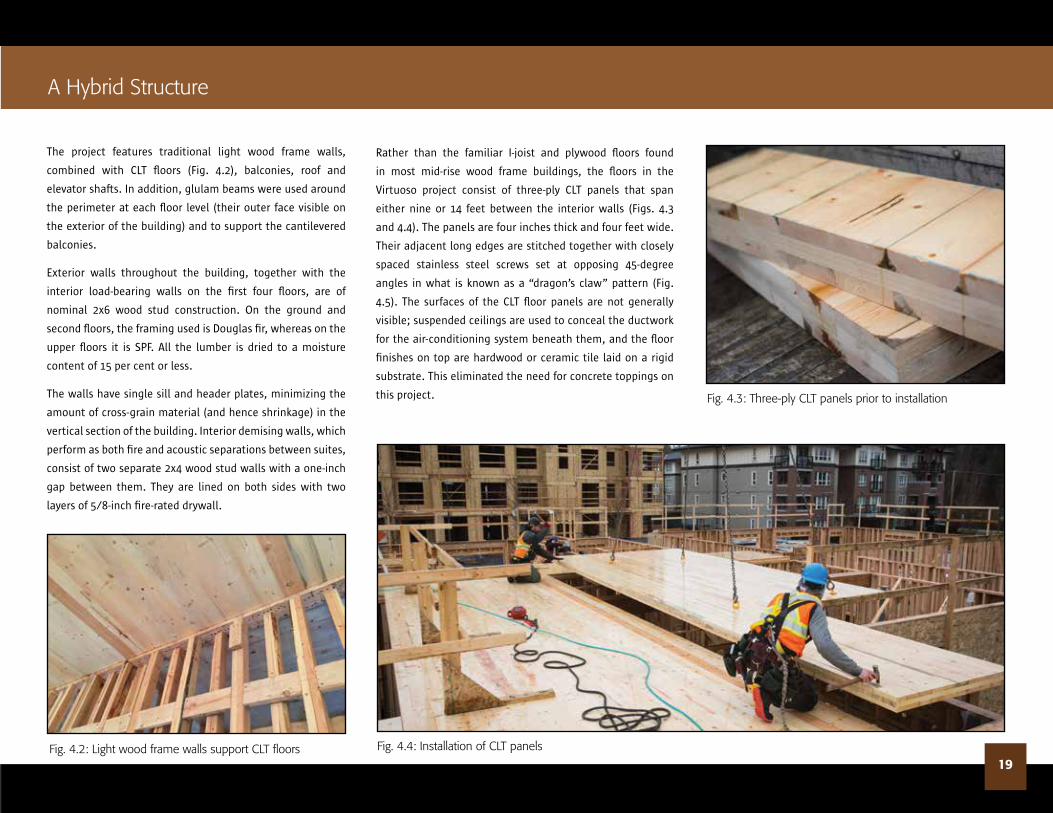
The project features traditional light wood frame walls,
combined with CLT floors (Fig. 4.2), balconies, roof and
elevator shafts. In addition, glulam beams were used around
the perimeter at each floor level (their outer face visible on
the exterior of the building) and to support the cantilevered
balconies.
Exterior walls throughout the building, together with the
interior load-bearing walls on the first four floors, are of
nominal 2x6 wood stud construction. On the ground and
second floors, the framing used is Douglas fir, whereas on the
upper floors it is SPF. All the lumber is dried to a moisture
content of 15 per cent or less.
The walls have single sill and header plates, minimizing the
amount of cross-grain material (and hence shrinkage) in the
vertical section of the building. Interior demising walls, which
perform as both fire and acoustic separations between suites,
consist of two separate 2x4 wood stud walls with a one-inch
gap between them. They are lined on both sides with two
layers of 5/8-inch fire-rated drywall.
Fig. 4.2: Light wood frame walls support CLt floors
A Hybrid structure
19
Rather than the familiar I-joist and plywood floors found
in most mid-rise wood frame buildings, the floors in the
Virtuoso project consist of three-ply CLT panels that span
either nine or 14 feet between the interior walls (Figs. 4.3
and 4.4). The panels are four inches thick and four feet wide.
Their adjacent long edges are stitched together with closely
spaced stainless steel screws set at opposing 45-degree
angles in what is known as a “dragon’s claw” pattern (Fig.
4.5). The surfaces of the CLT floor panels are not generally
visible; suspended ceilings are used to conceal the ductwork
for the air-conditioning system beneath them, and the floor
finishes on top are hardwood or ceramic tile laid on a rigid
substrate. This eliminated the need for concrete toppings on
this project. Fig. 4.3: three-ply CLt panels prior to installation
Fig. 4.4: Installation of CLt panels
20
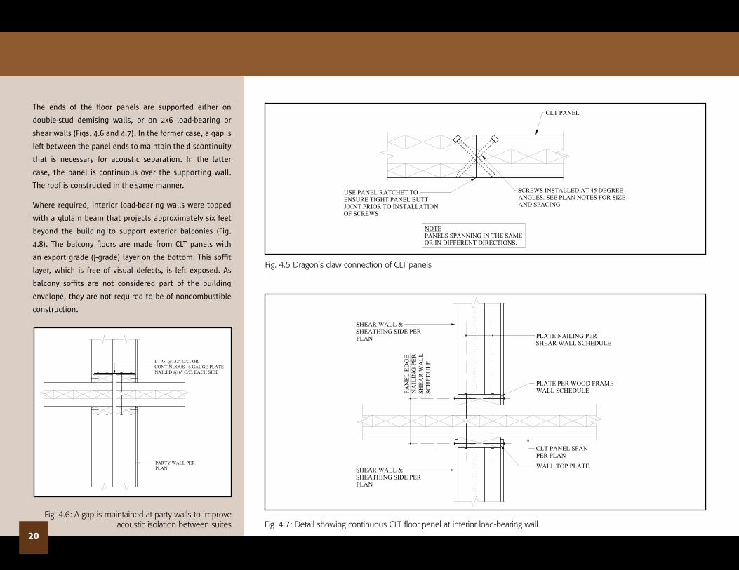
The ends of the floor panels are supported either on
double-stud demising walls, or on 2x6 load-bearing or
shear walls (Figs. 4.6 and 4.7). In the former case, a gap is
left between the panel ends to maintain the discontinuity
that is necessary for acoustic separation. In the latter
case, the panel is continuous over the supporting wall.
The roof is constructed in the same manner.
Where required, interior load-bearing walls were topped
with a glulam beam that projects approximately six feet
beyond the building to support exterior balconies (Fig.
4.8). The balcony floors are made from CLT panels with
an export grade (J-grade) layer on the bottom. This soffit
layer, which is free of visual defects, is left exposed. As
balcony soffits are not considered part of the building
envelope, they are not required to be of noncombustible
construction.
SCREWS INSTALLED AT 45 DEGREEANGLES. SEE PLAN NOTES FOR SIZEAND SPACING
USE PANEL RATCHET TOENSURE TIGHT PANEL BUTTJOINT PRIOR TO INSTALLATIONOF SCREWS
CLT PANEL
NOTEPANELS SPANNING IN THE SAMEOR IN DIFFERENT DIRECTIONS.
Fig. 4.5 dragon’s claw connection of CLt panels
Fig. 4.7: detail showing continuous CLt floor panel at interior load-bearing wall
LTP5 @ 32" O/C. ORCONTINUOUS 16 GAUGE PLATENAILED @ 6" O/C. EACH SIDE
PARTY WALL PERPLAN
Fig. 4.6: A gap is maintained at party walls to improve acoustic isolation between suites
SHEAR WALL &SHEATHING SIDE PERPLAN
PLATE PER WOOD FRAMEWALL SCHEDULE
CLT PANEL SPANPER PLAN
WALL TOP PLATESHEAR WALL &SHEATHING SIDE PERPLAN
PAN
EL E
DG
EN
AIL
ING
PER
SHEA
R W
ALL
SCH
EDU
LE
PLATE NAILING PERSHEAR WALL SCHEDULE

21
Three-ply CLT was also used for the walls of the elevator shafts. These panels are set vertically and connected with a “dragon’s
claw” arrangement of screws. For the shorter side of the elevator shaft, only a single panel was required, whereas for the longer
side, two panels were needed, placed side-by-side. The shaft is continuous, meaning that where it passes through each floor, the
edge of the CLT floor panels is supported on a ledge (Fig. 4.9). These shafts are not part of the lateral system for the building,
which consists entirely of shear walls that are located between suites and along corridors. These shear walls are of light wood
frame construction with plywood sheathing on one or both sides.
CLT BALC. PANELJ-GRADE @ U/S OF PANEL @
EXPOSED AREAS C/W STAINED FINISH
CLT ROOF PANELJ-GRADE @ U/S OF PANEL @
EXPOSED AREAS C/W STAINED FINISH
GLULAM STRUCTURAL BEAMAND GLULAM BEAM BEYOND
GLULAM STRUCTURAL BEAMBEYOND
EQ. EQ.CLT PANEL PERPLAN
NON COMPRESSIBLEMATERIAL PER ARCH.
1 5/8" Ø HOLE INCLT PANEL
1" V
ERTI
CA
LTR
AV
EL
CLT ELEVATOR WALL
BEAM PER PLAN, C/W:1- 5/8" Ø
BENT PLATES PER ELEVATORMANUFACTURER, BUT MIN. 1/4" THICK.EACH PLATE C/W: 4- 1/4" Ø x 3" LG.WOOD SCREWS EACH. DIP SCREWS INPL JOIST GLUE BEFORE INSTALLATION(MIN 2- 1/2" BETWEEN SCREWS)
NOTE:FOR BENT PLATELOCATIONS SEE ELEVATORSHOP DRAWINGS
11
Fig. 4.9: At the CLt elevator shafts, CLt floor panels are supported on a ledger
Fig. 4.8: detail section at balcony showing CLt floor panels supported on projecting glulam beams

22
A Virtual Model
Considerable time and effort was expended at the design
development stage to optimize panel layout, dimensions
and details, and to minimize waste and maximize
economy and efficiency. A 3-D model was produced
to identify each individual panel, its place within the
building and the location of any holes that needed to be
pre-drilled in the factory. These were mainly required to
accommodate the tie-down anchors that pass through
the shear walls, resisting uplift forces and increasing the
lateral resistance of the structure. These tie-downs, which
consist of sectional steel rods, must be accurately aligned
from top to bottom of the building to function effectively.
The remaining holes (for conduits, pipes, etc.) were drilled
on site.
The Virtuoso project has demonstrated that the use of CLT
floor and roof panels in a hybrid mass timber/light wood
frame application can offer shorter construction times.
The “just-in-time” delivery and easy installation of the
prefabricated panels (Fig. 4.10 and 4.11) can be quicker
and more efficient than traditional site construction.
Fig. 4.10: CLt floor panel being lifted into place by crane
Fig. 4.11: Aerial view of CLt floor being installed

CARBON CHARts CONCLusION
Since its introduction in the late 19th century, light wood
frame construction has continued to evolve, whether
in response to new code requirements, technological
advances or market expectations. As a renewable resource
that sequesters carbon and has low embodied energy,
wood has an increasingly important part to play in the
creation of more sustainable built environments (Fig. 5.1).
Now, with wood frame construction recognized as a key
component in the long-term mitigation of climate change,
the technology is being asked to deliver larger buildings
that are more durable and use less energy over their
service life.
As The Heights, King Edward Villa and Virtuoso have
demonstrated, light wood frame construction, in pure or
hybrid form, can meet or exceed these new expectations.
The success of these projects sets an important precedent,
one that will instill confidence in other designers and
developers, and so move such innovative approaches into
the mainstream.
Fig. 5.1: Courtyard at Virtuoso23
the Heights King edward Villa Virtuoso
Carbon impacts of energy vary with the primary sources of energy generation. Coal and fossil-derived electricity, for example, has
a higher carbon footprint than hydroelectric generation. Likewise, the carbon footprint of vehicles varies with the type of vehicle.
Passenger vehicles are defined as two-axle four-tire vehicles, including passenger cars, vans, pickup trucks, and sport/utility vehicles.
The figures in this calculator are based on an aggregated average of passenger vehicles and homes in the United States.

PROVINCIAL PARTNERS
NATIONAL PARTNERS
NATIONAL FUNDERS PROVINCIAL FUNDER
FOR MORE INFORMATION ON WOOD WORKS!, CONTACT: www.wood-works.ca • WOOD WORKS! HELP DESK: [email protected]
BC Program1-877-929-9663
Alberta Program1-780-392-1952
Ontario Program1-866-886-3574
Québec Program1-418-650-7193 ext. 413
Atlantic Program1-902-667-3889
National Office1-800-463-5091
US Program1-858-243-1620
PROJeCt CRedIts
The heighTsOwner/Developer: 8th Avenue PropertiesArchitect: Cornerstone Architecturestructural engineer: Weiler smith Bowers ConsultingConstruction Manager: Peak ConstructionWood supplier: dick’s Lumber (Burnaby)
King eDWArD VillAOwner/Developer: Richard WongArchitect: GBL Architectsstructural engineer: Bryson Markulin ZickmantelMechanical/electrical engineer: sRC Construction Manager: Performance ConstructionWood Prefabricator: Mitsui HomesCode Consultant: Protection engineering
VirTuOsOOwner/Developer: Adera development CorporationArchitect: Rositch Hemphill Architectsstructural engineer: Wicke Herfst Maver Consulting Inc.Construction Manager: Adera development Corporationengineered Wood supplier: structurlam Products
Program