innovative insulation guideline - brita-in-pubs.com - start · interior conditions like thermal,...
TRANSCRIPT
1 Introduction
01 Why to use this technology Impact of the building envelope
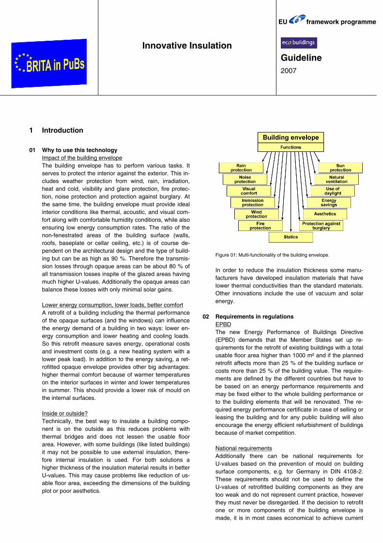
The building envelope has to perform various tasks. It serves to protect the interior against the exterior. This in-cludes weather protection from wind, rain, irradiation, heat and cold, visibility and glare protection, fire protec-tion, noise protection and protection against burglary. At the same time, the building envelope must provide ideal interior conditions like thermal, acoustic, and visual com-fort along with comfortable humidity conditions, while also ensuring low energy consumption rates. The ratio of the non-fenestrated areas of the building surface (walls, roofs, baseplate or cellar ceiling, etc.) is of course de-pendent on the architectural design and the type of build-ing but can be as high as 90 %. Therefore the transmis-sion losses through opaque areas can be about 80 % of all transmission losses inspite of the glazed areas having much higher U-values. Additionally the opaque areas can balance these losses with only minimal solar gains.
Lower energy consumption, lower loads, better comfort
A retrofit of a building including the thermal performance of the opaque surfaces (and the windows) can influence the energy demand of a building in two ways: lower en-ergy consumption and lower heating and cooling loads. So this retrofit measure saves energy, operational costs and investment costs (e.g. a new heating system with a lower peak load). In addition to the energy saving, a ret-rofitted opaque envelope provides other big advantages: higher thermal comfort because of warmer temperatures on the interior surfaces in winter and lower temperatures in summer. This should provide a lower risk of mould on the internal surfaces. Inside or outside? Technically, the best way to insulate a building compo-nent is on the outside as this reduces problems with thermal bridges and does not lessen the usable floor area. However, with some buildings (like listed buildings) it may not be possible to use external insulation, there-fore internal insulation is used. For both solutions a higher thickness of the insulation material results in better U-values. This may cause problems like reduction of us-able floor area, exceeding the dimensions of the building plot or poor aesthetics.
Figure 01: Multi-functionality of the building envelope.
In order to reduce the insulation thickness some manu-facturers have developed insulation materials that have lower thermal conductivities than the standard materials. Other innovations include the use of vacuum and solar energy.
02 Requirements in regulations EPBD The new Energy Performance of Buildings Directive (EPBD) demands that the Member States set up re-quirements for the retrofit of existing buildings with a total usable floor area higher than 1000 m² and if the planned retrofit affects more than 25 % of the building surface or costs more than 25 % of the building value. The require-ments are defined by the different countries but have to be based on an energy performance requirements and may be fixed either to the whole building performance or to the building elements that will be renovated. The re-quired energy performance certificate in case of selling or leasing the building and for any public building will also encourage the energy efficient refurbishment of buildings because of market competition. National requirements Additionally there can be national requirements for U-values based on the prevention of mould on building surface components, e.g. for Germany in DIN 4108-2. These requirements should not be used to define the U-values of retrofitted building components as they are too weak and do not represent current practice, however they must never be disregarded. If the decision to retrofit one or more components of the building envelope is made, it is in most cases economical to achieve current
EU framework programme
Innovative Insulation
Guideline 2007

− 1 −
practice or more. A calculation of the ratio between in-vestment costs and the energy cost savings within a de-fined time frame can be used to find out what is the most economic solution. In the case of Germany the Energieeinsparverordnung of 2002 defines the maximum U-values of new opaque building components and their replacement or renewal in existing buildings with a heating temperature of 19 °C or more as follows. For each European region (Central, North, South and East) the requirements are given for a representative country: Table 02: Maximum U-Values of retrofitted opaque building compo-nents in different countries.
Coun-try
Component Definition Maximum U-value
[ W/m²K ]
generally, internal in-sulation
0.45 Exterior wall
overcladding in form of slabs
0.35
Ceilings, roofs, pitched roof areas
steep roofs 0.30
Roofs flat roofs 0.25
external insulation 0.40 Ger
man
y (C
entr
al)
Ceilings and walls towards unheated rooms or ground internal insulation 0.50
External wall generally, internal in-sulation or in between inner and outer wall
0.40
Ceilings, roofs, pitched roof areas
roof construction 0.25
Floors with floor heating
against heated rooms 0.70
Den
mar
k (N
orth
)
Slab on ground floor, cellar ceiling
floor construction 0.30
Exterior wall
- Milan: zone E
- Rome: zone D
- Palermo: zone B
generally in between inner and outer wall, external *
E: 0.46
D: 0.50
B: 0.64 Ceilings, roofs, pitched roof areas
- Milan: zone E
- Rome: zone D
- Palermo: zone B
roof constructions *
E: 0.43
D: 0.46
B: 0.60
Italy
(S
outh
)
Floors towards unheated rooms or ground
- Milan: zone E
- Rome: zone D
- Palermo: zone B
floor constructions *
E: 0.43
D: 0.46
B: 0.60
Cze
ch R
epub
lic
(Eas
t)
There are currently no requirements on U-values for opa-que building components in building retrofits in the Czech Republic. If a building retrofit involves public funding or the total energy consumption of a building is higher than 700 GJ/year the building has to comply with the require-ments of the decree 291/2001 Sb. The decree 291/2001 Sb. “Efficiency of energy use in buildings” sets the require-ments on the specific energy consumption (kWh/m³a) with regard to the surface/volume ratio of a building.
* for Italy: values for major refurbishments and valid until 31/12/2007
2 Current practice
The current practice for the energy-efficient retrofit of non-transparent building components differs from country to country dependent on the climate and other influences
including politics. The materials used include cork, coco, wood-fibre boards, cellulose, foam glass, mineral wool, fibreglass, extruded polystyrene, expanded polystyrene, polyurethane boards, perlite. The most often used mate-rials are wood-fibre boards (λ= 0.045 W/mK), mineral wool (λ= 0.035-0.040 W/mK) and expanded polystyrene (λ= 0.035-0.040 W/mK). These materials offer retrofit so-lutions for most situations and with the lowest investment costs. The following table gives an overview of which U-values and what kind of insulation material is currently mostly used in the different regions that participate in the project BRITA in PuBs: Table 2: Current practice for retrofitted buildings in different countries
Coun-try
Component Retrofit measure
Appr. U-value
for the to-tal con-struction
[ W/m²K ]
~ 8 cm composite thermal insulation (mineral wool or polystyrene insulation (λ= 0.04 W/mK) with plaster)
0.35
Exterior wall gypsum board, moisture barrier, ~ 6 cm internal insu-lation (polystyrene)
0.45
Pitched roofs ~ 12 cm of mineral wool or polystyrene (λ= 0.04 W/mK) between the rafters
0.30
Flat roofs ~ 8 cm of polyurethane (λ= 0.024 W/mK) on top of the concrete slab, sealing
0.25
Ger
man
y (C
entr
al)
Ceilings and walls towards unheated rooms or ground
~ 4 cm of mineral wool or polystyrene(λ= 0.04 W/mK) if on inner side with moisture barrier
or ~ 5 cm of wood-fibre boards
0.40/0.50
External wall ~ 20 cm insulation* 0.20
Floor ~ 20 cm insulation* 0.12
Den
mar
k (N
orth
)
Roof ~ 25 cm insulation* 0.15
External wall ~ 10 cm insulation between inner and outer wall**
0.45
Floor ~ 6 cm insulation** 0.50 Italy
(S
outh
)
Roof ~ 6 cm insulation** 0.50
External wall ~ 10 cm of polystyrene** 0.30
Floor above un-heated space or ground
~ 5 cm of polystyrene 0.60
Pitched roof ~ 12-15 cm of mineral wool between the rafters
0.30
Cze
ch R
epub
lic
(Eas
t)
Flat roof ~ 10 cm of polystyrene 0.25 * for Denmark is mentioned a construction fulfilling the new rules in building regulation from April 2006 when retrofitting ** for Italy the current practice is mentioned for the region Rome (zone D)
3 Innovative solutions
Within the last few years, besides using a higher thick-ness of insulation material, a trend towards incorporating high efficient insulation materials, has developed. In the following section some examples are presented, along with some insights. In order to reduce the insulation thickness some manufacturers have developed insulation
− 2 −
materials that have lower thermal conductivities than the standard materials. Other innovations include the use of vacuum and solar energy.
31 Higher thickness of insulation material in order to achieve a lower U-value Using higher thicknesses of the insulation material and/or using the same type of insulation material but with a lower thermal conductivity (e.g. mineral wool with λ=0.030 W/mK instead of 0.040 W/mK) is often used for improving the thermal quality of the building envelope. In the case of more complex component structures like, for example a roof built with rafters this can result in adding an additional insulation layer below or above the rafters. Pilot projects like the IEA Task 13 case study “Ultrahaus Rottweil” (1995) [1] have proven that external insulation of up to 40 cm thickness (U-value of wall: 0.11 W/m²K) can be glued to the outside wall without using anchors that would lead to thermal bridges. After now 12 years of use, the insulation material covered with a plaster layer is still in optimum condition. Generally, the higher thicknesses of wall insulation range between 15 and 30 cm of insulation (depending on the countries’ current practice). In the case that anchor con-structions are necessary this can lead to difficulties as the anchor systems are sometimes only available up to a certain length. The so-called passive or 3-litre-houses usually include thermal insulation to the roof of 30 cm and to the external wall of 20 cm or more. Figure 31: Photo of the 40 cm insulation material (mineral wool) at the “Ultrahaus” in Rottweil, Germany.
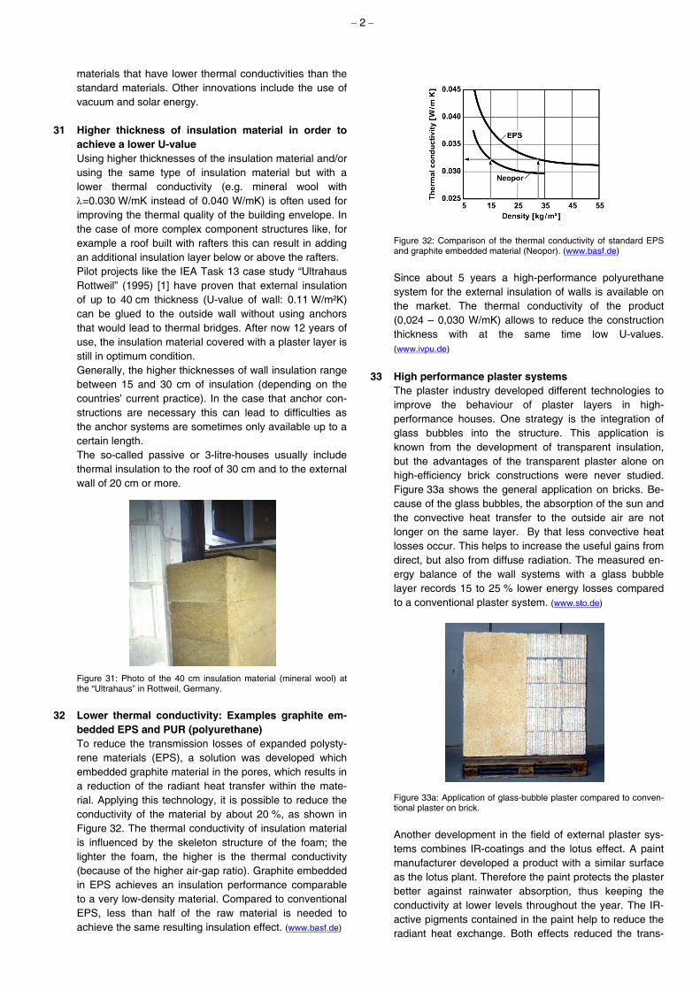
32 Lower thermal conductivity: Examples graphite em-bedded EPS and PUR (polyurethane) To reduce the transmission losses of expanded polysty-rene materials (EPS), a solution was developed which embedded graphite material in the pores, which results in a reduction of the radiant heat transfer within the mate-rial. Applying this technology, it is possible to reduce the conductivity of the material by about 20 %, as shown in Figure 32. The thermal conductivity of insulation material is influenced by the skeleton structure of the foam; the lighter the foam, the higher is the thermal conductivity (because of the higher air-gap ratio). Graphite embedded in EPS achieves an insulation performance comparable to a very low-density material. Compared to conventional EPS, less than half of the raw material is needed to achieve the same resulting insulation effect. (www.basf.de)
Figure 32: Comparison of the thermal conductivity of standard EPS and graphite embedded material (Neopor). (www.basf.de) Since about 5 years a high-performance polyurethane system for the external insulation of walls is available on the market. The thermal conductivity of the product (0,024 – 0,030 W/mK) allows to reduce the construction thickness with at the same time low U-values. (www.ivpu.de)
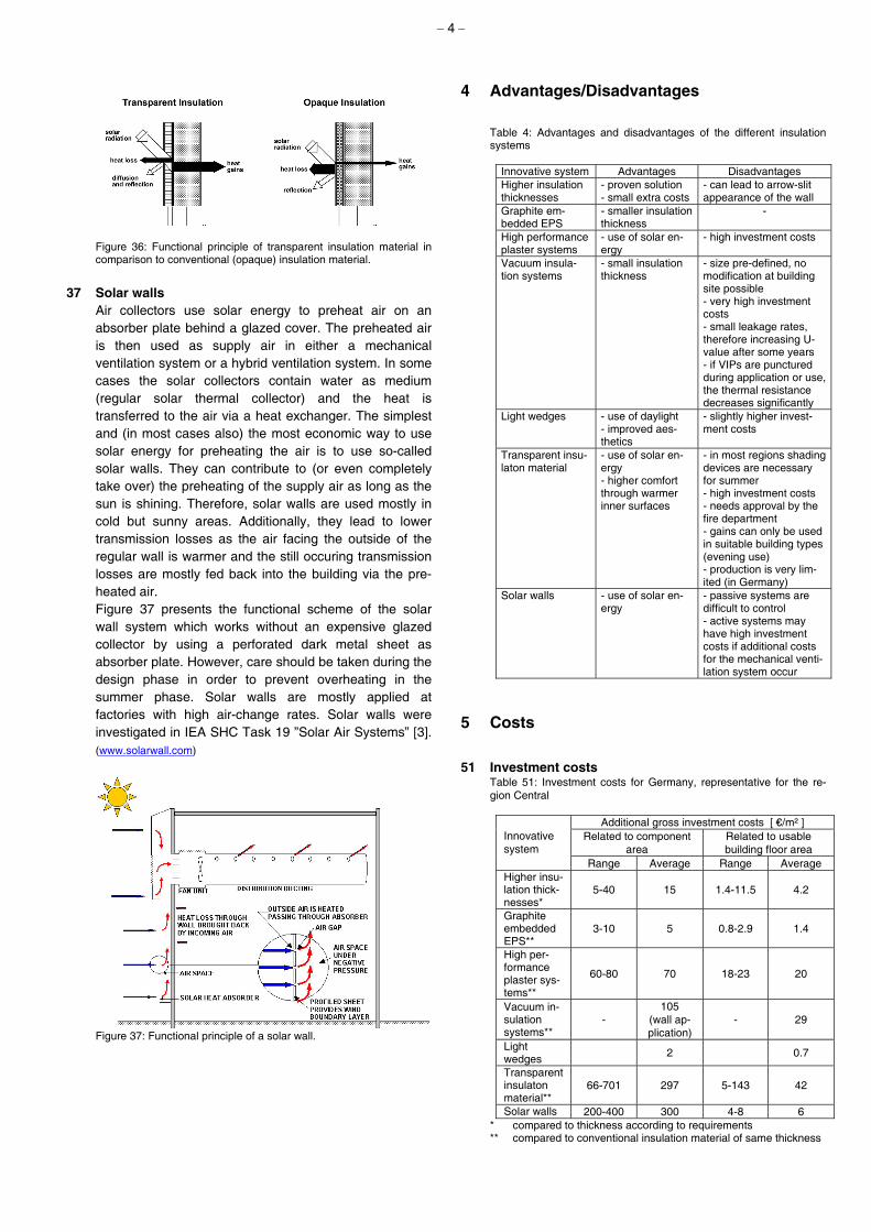
33 High performance plaster systems The plaster industry developed different technologies to improve the behaviour of plaster layers in high-performance houses. One strategy is the integration of glass bubbles into the structure. This application is known from the development of transparent insulation, but the advantages of the transparent plaster alone on high-efficiency brick constructions were never studied. Figure 33a shows the general application on bricks. Be-cause of the glass bubbles, the absorption of the sun and the convective heat transfer to the outside air are not longer on the same layer. By that less convective heat losses occur. This helps to increase the useful gains from direct, but also from diffuse radiation. The measured en-ergy balance of the wall systems with a glass bubble layer records 15 to 25 % lower energy losses compared to a conventional plaster system. (www.sto.de) Figure 33a: Application of glass-bubble plaster compared to conven-tional plaster on brick.
Another development in the field of external plaster sys-tems combines IR-coatings and the lotus effect. A paint manufacturer developed a product with a similar surface as the lotus plant. Therefore the paint protects the plaster better against rainwater absorption, thus keeping the conductivity at lower levels throughout the year. The IR-active pigments contained in the paint help to reduce the radiant heat exchange. Both effects reduced the trans-

− 3 −
mission losses of exterior wall systems, in combination with a highly absorptive colour applied onto the south surface. The IR-coating also leads to higher surface tem-peratures, thus significantly reducing the risk of microor-ganisms contaminating outside surfaces of high perform-ance buildings, a problem that was caused by better in-sulation. Figure 33b gives an impression of this develop-ment; the physical effects are not visible in the structure of the plaster itself. The plaster system is offered in a wide range of colours. (www.sto.de) Figure 33b: Application of an IR-coated plaster system with lotus ef-fects. An interior plaster development is concentrating on the integration of phase change materials (PCM) into the structure. Here, micro-encapsulated wax droplets are in-tegrated into the plaster. By this method, some extra thermal capacity is added to the plaster, to perform better on temperature peaks. This increases the passive solar gains in winter and decreases the risk of overheating in summer. The development is in an early stage; therefore, only laboratory tests exist. Experiences in the 70s at MIT gave a very small effect on the reduction of temperature peaks. (www.ise.fhg.de/english/press/pi_2001/pi05_2001.html) Figure 33c: Principle scheme of micro-encapsulated PCM in plas-ters. (www.basf.de)
34 Vacuum insulation systems A new application of vacuum evacuated building ele-ments is being developed by the insulation industry. The thermal conductivity of this material is reduced by more than factor 10 compared to conventional materials. This leads to much slimmer constructions of high-performance houses. The evacuated silica gel material is covered by a high-performance aluminium foil. The gas pressure in the construction is approx. 1 mbar, the leakage rate is pre-dicted to be below 2 mbar per year. To make the units applicable to construction conditions, the elements are glued into a polystyrene cover. Thus, the material is pro-tected from any sharp edges during transportation or mounting. Other disadvantages are that the construction boards are manufactured in certain sizes and that no site
forming is possible. Also there is the price, which can be more than 10 times as high as conventional materials. Within the framework of IEA Annex 39, the quality of vacuum insulation products (VIP) and possible applica-tions are investigated. Figure 34: Vacuum insulation material panel compared to mineral wool panel of the same thermal resistance. (www.vip-bau.ch)
35 Light wedges
As a result of increasing insulation thicknesses, several manufacturers have developed special solutions for the wall/window joint to prevent the so-called arrow-slit archi-tecture and to increase the amount of daylight coming in through the windows. “Light wedges”, that are expanding towards the external surface of the insulation system, al-low for a higher yield of daylight. (www.marmorit.de)
Figure 35: Light wedges in insulation systems allow a better use of daylight. (www.mamorit.de)
36 Transparent insulation material
Transparent insulation improves the thermal performance of the exterior wall not only by reducing the transmission losses but also by enabling solar gains. Figure 36 shows the functional principle of transparent insulation in comparison with opaque insulation. The solar radiation on the wall is transmitted through the insulation material and absorbed at the dark coloured exterior surface of the inner shell of the wall and converted to heat. The insulation material in front ensures that a large part of the gained heat is transfered to the inner shell of the wall. Depending on the amount of solar radiation and the external temperature the transmission loss is reduced or the heat transfer is reversed. In the latter case the transparent insulation acts as heating system. The inner shell works as a storage system and controls the time delay of the heat transfer from outside to inside (depending on its thermal capacity).
− 4 −
Figure 36: Functional principle of transparent insulation material in comparison to conventional (opaque) insulation material.
37 Solar walls
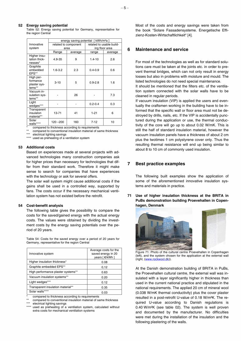
Air collectors use solar energy to preheat air on an absorber plate behind a glazed cover. The preheated air is then used as supply air in either a mechanical ventilation system or a hybrid ventilation system. In some cases the solar collectors contain water as medium (regular solar thermal collector) and the heat is transferred to the air via a heat exchanger. The simplest and (in most cases also) the most economic way to use solar energy for preheating the air is to use so-called solar walls. They can contribute to (or even completely take over) the preheating of the supply air as long as the sun is shining. Therefore, solar walls are used mostly in cold but sunny areas. Additionally, they lead to lower transmission losses as the air facing the outside of the regular wall is warmer and the still occuring transmission losses are mostly fed back into the building via the pre-heated air. Figure 37 presents the functional scheme of the solar wall system which works without an expensive glazed collector by using a perforated dark metal sheet as absorber plate. However, care should be taken during the design phase in order to prevent overheating in the summer phase. Solar walls are mostly applied at factories with high air-change rates. Solar walls were investigated in IEA SHC Task 19 ”Solar Air Systems” [3]. (www.solarwall.com)
Figure 37: Functional principle of a solar wall.
4 Advantages/Disadvantages
Table 4: Advantages and disadvantages of the different insulation systems
Innovative system Advantages Disadvantages Higher insulation thicknesses
- proven solution - small extra costs
- can lead to arrow-slit appearance of the wall
Graphite em-bedded EPS
- smaller insulation thickness
-
High performance plaster systems
- use of solar en-ergy
- high investment costs
Vacuum insula-tion systems
- small insulation thickness
- size pre-defined, no modification at building site possible - very high investment costs - small leakage rates, therefore increasing U-value after some years - if VIPs are punctured during application or use, the thermal resistance decreases significantly
Light wedges - use of daylight - improved aes-thetics
- slightly higher invest-ment costs
Transparent insu-laton material
- use of solar en-ergy - higher comfort through warmer inner surfaces
- in most regions shading devices are necessary for summer - high investment costs - needs approval by the fire department - gains can only be used in suitable building types (evening use) - production is very lim-ited (in Germany)
Solar walls - use of solar en-ergy
- passive systems are difficult to control - active systems may have high investment costs if additional costs for the mechanical venti-lation system occur
5 Costs
51 Investment costs Table 51: Investment costs for Germany, representative for the re-gion Central
Additional gross investment costs [ €/m² ] Related to component
area Related to usable building floor area
Innovative system
Range Average Range Average Higher insu-lation thick-nesses*
5-40 15 1.4-11.5 4.2
Graphite embedded EPS**
3-10 5 0.8-2.9 1.4
High per-formance plaster sys-tems**
60-80 70 18-23 20
Vacuum in-sulation systems**
- 105
(wall ap-plication)
- 29
Light wedges 2 0.7
Transparent insulaton material**
66-701 297 5-143 42
Solar walls 200-400 300 4-8 6 * compared to thickness according to requirements ** compared to conventional insulation material of same thickness
− 5 −
52 Energy saving potential Table 52: Energy saving potential for Germany, representative for the region Central
energy saving potential [ kWh/m²a ] related to component
area related to usable build-
ing floor area Innovative system
Range average range average Higher insu-lation thick-nesses*
4.9-35 9 1.4-10 2.6
Graphite embedded EPS**
1.6-3.2 2.3 0.4-0.9 0.6
High per-formance plaster sys-tems**
3-10 5 0.9-2.8 1.6
Vacuum in-sulation sys-tems**
- 26 - 7.3
Light wedges*** - - 0.2-0.4 0.3
Transparent insulaton material**
13-71 41 1-21 6
Solar walls**** 120 –200 160 7-12 10
* compared to thickness according to requirements ** compared to conventional insulation material of same thickness *** electrical lighting savings **** used as preheating of a ventilation system
53 Additional costs
Based on experiences made at several projects with ad-vanced technologies many construction companies ask for higher prices than necessary for technologies that dif-fer from their standard work. Therefore it might make sense to search for companies that have experiences with the technology or ask for several offers. The solar wall system might cause additional costs if the gains shall be used in a controlled way, supported by fans. The costs occur if the necessary mechanical venti-lation system has not existed before the retrofit.
54 Cost-benefit analysis
The following table gives the possibility to compare the costs for the saved/gained energy with the actual energy costs. The values were obtained by dividing the invest-ment costs by the energy saving potentials over the pe-riod of 20 years. Table 54: Costs for the saved energy over a period of 20 years for Germany, representative for the region Central
Innovative system Average costs for the saved energy in 20
years [ €/kWh ]
Higher insulation thickness* 0.08
Graphite embedded EPS** 0,12
High performance plaster systems** 0.63
Vacuum insulation systems** 0.20
Light wedges*** 0.12
Transparent insulation material** 0.35 Solar walls**** 0.03
* compared to thickness according to requirements ** compared to conventional insulation material of same thickness *** electrical lighting savings **** used as preheating of a ventilation system, calculated without
extra costs for mechanical ventilation systems
Most of the costs and energy savings were taken from the book “Solare Fassadensysteme. Energetische Effi-zienz-Kosten-Wirtschaftlichkeit“ [4].
6 Maintenance and service
For most of the technologies as well as for standard solu-tions care must be taken at the joints etc. in order to pre-vent thermal bridges, which can not only result in energy losses but also in problems with moisture and mould. The listed technologies do not need special maintenance. It should be mentioned that the filters etc. of the ventila-tion system connected with the solar walls have to be cleaned in regular periods. If vacuum insulation (VIP) is applied the users and even-tually the craftsmen working in the building have to be in-formed that the specific wall or floor area must not be de-stroyed by drills, nails, etc. If the VIP is accidentally punc-tured during the application or use, the thermal conduc-tivity of the core will go up to about 0.02 W/mK. This is still the half of standard insulation material, however the vacuum insulation panels have a thickness of about 2 cm plus the twotimes 1 cm polystyrene cover only. Thus the resulting thermal resistance will end up being similar to about 8 to 10 cm of commonly used insulation.
7 Best practice examples
The following built examples show the application of some of the aforementioned innovative insulation sys-tems and materials in practice.
71 Use of higher insulation thickness at the BRITA in PuBs demonstration building Proevehallen in Copen-hagen, Denmark
Figure 71: Photo of the cultural centre Proevehallen in Copenhagen (left), and the system chosen for the application at the external wall (right, (www.rockwool.dk)).
At the Danish demonstration building of BRITA in PuBs, the Proevehallen cultural centre, the external wall was in-sulated with a layer significantly higher in thickness than used in the current national practice and stipulated in the national requirements. The applied 20 cm of mineral wool (0.038 W/mK thermal conductivity) plus the cover plaster resulted in a post-retrofit U-value of 0.18 W/m²K. The re-quired U-value according to Danish regulations is 0.40 W/m²K (see table 02). The system is well proven and documented by the manufacturer. No difficulties were met during the installation of the insulation and the following plastering of the walls.

− 6 −
72 Use of graphite embedded EPS at the nursing home Stuttgart-Sonnenberg, Germany
Figure 72: Photos of the retrofitted nursing home in Stuttgart-Sonnenberg (left) and of the application of the graphite embedded EPS-system (grey) on the south and north side of the building (right). The graphite embedded EPS system was applied be-cause the planned transparent insulation system could not be used as a result of technical problems at the manufacturer. The design team looked for a system that would be easy to include at a late state of planning and would be at least as energy-efficient as the formerly planned system. They came up with replacing the origi-nally planned 20 cm polystyrene insulation with λ=0.040 W/mK by a 20 cm EPS-system (λ=0.035 W/mK). The energy savings realised were bigger than calculated with the transparent insulation (smaller area covered). No problems occurred during the construction and in use (2 years at the time of the preparation of the guideline). (www.ensan.de)
73 Use of transparent insulation at a multi-family house in Munich
Figure 73: Photos of the multi-family house in Munich (left), and of the application of transparent insulation at the exterior wall of the top floor (right).
Different innovative systems were installed at the exterior wall of the top floor of the building. These systems in-cluded solar air and solar water collectors as well as transparent insulation panels manufactured by 2 different companies. The effects of these systems were measured for 2 years. For walls with transparent insulation material care has to be taken in order to prevent overheating problems in the rooms behind the walls. To counteract these problems, manufacturers either restrict the solar gains by using solar protection glazing (e.g. WICONA) or they limit the size of the panels (e.g. STO). The experi-ence at Munich was that the system with solar protection glazing led to lower summer temperatures; on the other hand less reduction of the heating energy consumption was achieved. However the users did not complain about too high wall temperatures with any of the systems. Be-cause of the time shift between the solar gains and the emission of the heat to the room, a transparent insulation system only makes sense in buildings that are used in
the evenings and have heavy outside wall constructions. (www.ibp.fraunhofer.de/wt)
74 Use of vacuum insulation panels at the community centre Guter Hirte in Ulm, Germany
Figure 74: Photo of the retrofitted community centre in Ulm (left), here kindergarden, and of the application of vacuum insulation pan-els at the floor of the kindergarden (right). In this retrofit project vacuum insulation panels (VIPs) were used in the floor of the kindergarden and as exterior insulation (between two layers of polystyrene) at the wall of the parish hall. Especially the use at the floor area showed advantages as the insulation thickness was very small and at the same time a good U-value was achieved. Therefore no steps or new doors were neces-sary. However the use of VIPs for the floor level required careful planning. The border of the floor area had to be insulated with polystyrene as the panels can not be cut. Also below and above the VIPs additional insulation lay-ers had to be included to protect the material and act as acoustic insulation. (www.ensan.de)
8 Calculation tools
- How to calculate a U-value: ISO 6946, available at national standardisation body publishers, e.g. for Germany Beuth Publishing, Berlin. - How to calculate thermal bridges: ISO 10211-2, ISO
14683, available at national standardisation body publishers, e.g. for Germany Beuth Publishing, Ber-lin.
- Libraries for thermal conductivities: e.g. DIN 4108-4, available at Beuth Publishing, Berlin. - Tools for developing a retrofit strategy: - Energy Concept Adviser of IEA Annex 36 (ECA), www.annex36.com
- BRITA in PuBs information tool (BIT), www.brita-in-pubs.com
- EPIQR: a cost predictive European retrofitting evaluation method for existing apartment build- ings, www.epiqr.de, www.epiqr.fr, etc.
- Tool for a holistic calculation of the net, final and pri-mary energy demand of non-residential buildings ac-cording to the German DIN V 18599: ibp18599, www.ibp18599.de
- Tool for checking the dew problem in the component: Wärme und Feuchte instationär (WUFI), www.ibp.fraunhofer.de/downloads

− 7 −
9 References
91 Compilation This guideline is written as a part of the project BRITA in PuBs – Bringing retrofit innovation to application in public buildings, EU 6th framework programme Eco-building (TREN/04/FP6EN/S.07.31038/503135). The authors are Heike Erhorn-Kluttig and Hans Erhorn from the Fraunhofer Institute of Building Physics, Ger-many. Input for the tables on maximum U-values and cur-rent practice in different countries was provided by Kirsten Engelund Thomsen (SBi), Marco Citterio (ENEA), Marco Beccali (University of Palermo), Simone Ferrari (Politecnico di Milano) and Pavel Charvat (University of Technology, Brno). Ove Mørck (Cenergia) contributed with information on the best practice example Proevehal-len. Special thanks to Kirsten Engelund Thomsen and Gilbert Snook (City College Plymouth) for giving feed-back to the guideline. The professional editing was closed in May 2007.
92 Further reading Insulation material and system manufacturers: - BASF Aktiengesellschaft: http://www.basf.de
- Rockwool: www.rockwool.com - Isover: www.isover.com
- STO: www.sto.com
- WICONA: www.wicona.com
- IVPU-Industrieverband Polyurethan-Hartschaum e.V.: http://www.ivpu.de/
- KNAUF MARMORIT GmbH: http://www.marmorit.de
- Conserval Engineering Inc.: www.solarwall.com
93 Literature
[1] A. G. Hestnes, et alii (edit.): Solar Low Energy Houses - Strategies, Technologies, Examples. ISBN 1-873936-69-9. James&James publishing, London, UK (1997). [2] R. S. Hastings (edit.): IEA SHC Task 28 Handbook, James&James publishing, London, UK. [3] R. S. Hastings (edit.): IEA SHC Task 19 Handbook, James&James publishing, London, UK. [4] J. Reiß, M. Wenning, H. Erhorn, L. Rouvel: Solare Fassadensysteme. Energetische Effizienz-Kosten-Wirt-schaftlichkeit. IRB-Verlag, Stuttgart, Germany (2005). ISBN 3-8167-6433-9. (in German) Internet: - Fraunhofer-Institut fuer Bauphysik IBP: www.ibp.fraunhofer.de/wt - Fraunhofer-Institut fuer Solare Energiesysteme ISE: http://www.ise.fhg.de/english/press/pi_2001/pi05_2001.html
- FHBB Institut fuer Energie: http://www.vip-bau.ch/ (in Ger- man) - Energetische Verbesserung der Bausubstanz (Bei-
spielgebäude = case studies): www.ensan.de (in Ger-man)
10 Disclaimer
The sole responsibility for the content of this publication lies with the authors. It does not represent the opinion of the Community. The authors and the European Commis-sion are not responsible for any use that may be made of the information contained therein.