innovative stripper configurations to reduce the energy ... · innovative stripper configurations...
TRANSCRIPT
Innovative Stripper Configurations to Reduce the Energy Cost of CO2 Capture
by Gary T. Rochelle ([email protected]) Department of Chemical Engineering
The University of Texas at Austin Austin, Texas 78712
Prepared for the poster session at the Second Annual Carbon Sequestration Conference, Alexandria, VA, May 5-8, 2003
Abstract CO2 capture by absorption/stripping with aqueous monoethanolamine (MEA) is the state-of-the-art technology for CO2 capture from coal-fired power plants. The energy consumption in stripping can be 15 of 30% of the power plant output. A rigorous rate-based model was used to simulate several flowsheet alternatives that reduce the energy requirement by 5 to 20%: 1. A larger cross exchanger to reduce the T approach from 10 to 5oC; 2. Vapor compression to recover latent heat from the stripper overhead; 3. Multipressure stripping to integrate with the CO2 compressor; and 4. Intercooling in the Absorber. The model was also used to simulate the effects of using a more reactive solvent.
Introduction CO2 removal and compression is required for CO2 capture and sequestration from combustion gases and other gases to avoid global climate change. Existing technology is energy intensive and uses large quantities of moderate level heat. This paper presents modified flowsheets for the absorption/stripping process with aqueous monoethanolamine (MEA) that will reduce the overall energy requirement and shift much of the load from heat to power.
These processes may also be used in CO2 removal from hydrogen or syngas where the CO2 is further compressed for production of methanol or enhanced oil recovery or for sequestration.
Absorption/stripping with aqueous solvents such as alkanolamines and promoted potassium carbonate is known, effective technology for removing CO2. In a simple absorption/stripping process the heat required for the stripper reboiler is significant. In application on a coal-fired power plant the required heat can reduce net power production by as much as 15 to 30%. An aqueous solvent of monoethanolamine has been used in several small applications on CO2 removal from flue gas.
In simple absorption/stripping as currently practiced, the aqueous solvent is regenerated at 100 – 120oC in a simple, countercurrent, reboiled stripper operated at a single pressure, usually 1 – 2 atm. The rich solvent feed is preheated by cross-exchange with hot lean solvent product to within 5 to 30oC of the stripper bottoms. The overhead vapor is cooled to condense water, which is returned as reflux to the countercurrent stripper. When used for CO2 sequestration and other applications the product CO2 is compressed to 100 –150 atm.
Energy efficiency can be enhanced by recovery of useful heat from the overhead condenser. The overhead vapor can contain 1 to 5 moles of water vapor for every mole of CO2. In vapor recompression the overhead vapor is compressed by a factor of 2 to 10, then exchanged with the bottoms liquid to provide heat for the reboiler. With multi-effect strippers, two or more strippers are operated in parallel, but each stripper is operated at a significantly different pressure. The vapor from a higher pressure stripper is used to heat the reboiler of a lower pressure stripper in a cascade arrangement. Both of these configurations result in the loss of exergy in the required heat exchanger.
Energy consumption may also be reduced by adding one or more stages of adiabatic or isothermal (heated) flash before the stripper or using a multistage, multipressure flash instead of the stripper. The rich, preheated solvent can be flashed in one or more stages to successively lower pressure with or without additional heating at each stage. If a stage is heated it may also be configured as a reboiled

stripper with countercurrent contacting in a trayed or packed column. Vapor from each stage can be cooled to condense water and the CO2 product can be compressed and combined with product from other stages. This paper presents the new concept of a multipressure stripper. The vapor from each stage of a multipressure flash is compressed and used a stripping vapor in a successively higher pressure stage.
RateFrac Model
Freguia and Rochelle (2003) developed and validated a model of the conventional MEA absorption/stripping process using ASPENPLUS with RATEFRAC for both absorber and stripper. Freguia (2002) presents a base case of this model for a typical coal-fired power plant.
The absorber is modeled with kinetic reactions; the stripper with all equilibrium reactions. Equilibrium is calculated with an Electrolyte-NRTL model (Freguia, 2002), regressed on the data of Jou et al. (1995), using the Henry’s constant of CO2 in H2O. The kinetic model uses the following expression for the flux.
( *,2,2
2
2,22 ][)( iCOiCO
CO
COiMEACO aa
DMEAkAFN −=
γ) (1)
The driving force is activity based, with activities calculated by the Electrolyte-NRTL model. The square root dependence on rate constant and concentration of MEA at the interface is consistent with an interface-pseudo-first-order approximation (Freguia, 2002). The rate constant for the CO2+MEA reaction (k2,MEA) is the value of Hikita (1977), given in equation 2; AF is an adjustment factor, given in equation 3, to match wetted wall data from Dang (2001).
)(
215299.10 0,210 KTkLog MEA −= (2)
)(6.405032.11ln 0 KT
AF +−= (3)
The diffusivity of CO2 is calculated with a Stokes-Einstein correlation, given by equation 4 (Pacheco, 1998).
545.0
,22
=
solution
waterwaterCOCO DD
µµ
(4)
The viscosity of solution is calculated with a correlation by Weiland et al. (1996), which includes temperature, MEA concentration and CO2 loading dependences.
Table 2 gives the conditions of the base case run. The primary adjustment from the case by Freguia is the use of 2 atm pressure throughout the base case stripper.
Table 2. Input summary for the high CO2 base case.
Flue Gas
Composition (mol %) CO2 12.57%
(from EPA-600/2-75-006 H2O 7.77%
January 1975, table 4) N2 74.80%
O2 4.86%
Water Saturation T 45 0C
Absorber inlet T 55 0C
Absorber inlet P 111.325 Kpa
2

Mole flow
(after saturation) 11,000 kmol/hr
Solvent
Unloaded composition MEA 11.23 mol%
(30 wt% MEA) H2O 88.77 mol%
Lean loading 0.21
(mol CO2/mol MEA)
Lean solvent T 40 0C
CO2 removal 90%
(solvent rate calculated to get specified removal)
Absorber
Packing height 15 meters, 20 well-mixed sections
Diameter 7 meters
Pressure drop 10 Kpa
CO2+MEA kinetics From Dang (2001)
Packing type Cascade Mini Rings #2
Computational 20 well-mixed segments
Cross exchanger
T approach, hot end 10 0C
Stripper
Packing height 10 meters, 20 well-mixed sections
Diameter 4.5 meters
Reboiler Equilibrium stage
Rich solvent feed location top
Water reflux location top
Packing type Cascade Mini Rings #2
Reactions All at equilibrium
Computational 20 well-mixed segments
Compressor
Outlet pressure 130 atm
Intercooling T 40oC
Number of stages 4
Polytropic efficiency 75%
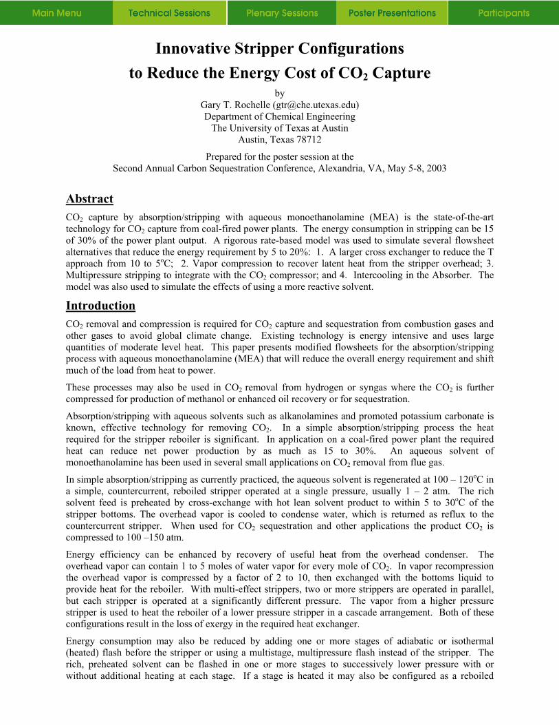
Base Case Results Figures 1 and 2 give the McCabe Thiele diagrams for the base case with a solvent rate that minimizes the heat rate in the stripper reboiler. The optimum solvent rate corresponds to a solvent capacity of 0.25 mol CO2/mol MEA. The lean solvent is “overstripped” such that there is no pinch in the absorber and an excessive driving force at the lean end of the absorber.
3
The CO2 driving force in the absorber is large at both ends. The ratio of the bulk partial pressure to the equilibrium partial pressure varies from about 5 at the rich end to more than 100 at the lean end. The operating line in the stripper is curved because the heat of desorption of CO2 is twice as large as that of H2O and because of the sensible heat effects of the solvent. The driving force in the stripper is well distributed. There appears to be no “pinch.”
Exergy analysis of base case The minimum work to separate 12% CO2 from flue gas at 40oC and 1 atm is given by:
Wmin = (RTo Σxiln xi)/xi
= 1.987 * 313 * (0.12 ln 0.12 + 0.88 ln 0.88)/0.12 = 1.9 kcal/gmol CO2
The minimum isothermal work to compress CO2 at 40oC from 1 atm to 2 atm or to 130 atm is given approximately by:
Wcomp = RT ln P2/P1
= 0.4 kcal/gmol to 2 atm or 2.7 kcal/gmol to 130 atm
Figure 1. Base Case Absorber Performance, 90% CO2 removal, ∆T=10oC
0
5
10
15
0.2 0.25 0.3 0.35 0.4 0.45
P CO
2 (KPa
)
CO2 loading (molCO
2/mol MEA)
Equilibrium
Operating
Figure 1. Base Case Absorber Performance, 90% CO2 removal, ∆T=10oC
4

Figure 2. Base Case Simple Stripper Performance, 2 atm, ∆T=10oC
0
10
20
30
40
50
0.2 0.25 0.3 0.35 0.4 0.45 0.
P CO
2 (KPa
)
CO2 loading (mol CO
2/ mol MEA)
60
5
Operating
Equilibrium
The apparent work with a simple stripper is given by a Carnot cycle efficiency with about 44 kcal of steam per gmol CO2 using steam that condenses at 130oC:
Steam work value = Q (Tstm – 313)/Tstm
= 44 kcal/gmol *(403-313)/403 = 9.8 kcal/gmol
The additional compression work to 130 atm with 75% efficiency in a four stage intercooled compressor is about 3.9 kcal/gmol CO2. Therefore the simple stripper system has an apparent thermodynamic efficiency of about 30% and the work loss is about 10.5 kcal/mol CO2.
The total work loss can be accounted for by several components. There are three major heat exchangers where inefficiency results from the temperature driving force and the lost work is given by:
Wloss = Q (∆T/T)
The greatest loss is in the condenser:
Condenser: Wlost = 20 * (363-313)/373 = 2.7 kcal/mol CO2
With steam condensing at 130oC, the reboiler loss is given by:
Reboiler: Wlost = 44 * 10/403 = 1.1 kcal/mol CO2
However, if steam at a greater pressure is used, the losses will also be greater. With a 10oC approach the loss in the cross exchanger and solvent cooler is given by:
Cross exchanger = 80oC *1 kcal/kgoC*/1.7m * 10oK/353oK = 1.3 kcal/mol CO2
Work is also lost as a result of the CO2 diffusion and driving force in the absorber and stripper. With mass transfer the lost work is given by:
Wlost = RT abs(ln (PCO2,gas/PCO2,equil))
The loss in the stripper is usually small with significant overstripping to maximize capacity. However, because of the overstripping and the poor mass transfer rates in the absorber, the work loss on absorption is significant:
PCO2,gas/PCO2,equil = 5 at rich end
PCO2,gas/PCO2,equil = 100 at lean end
Wlost = 1.987*323*ln(23) = 1.5 kcal/mol CO2
5

The losses because of nonisothermal, inefficient compression from 2 atm to 130 atm are given by:
Compressor loss = 3.9 – 2.7 = 1.2 kcal/mol CO2
Table 1 summarizes these work losses. Almost 95% of the inefficiencies are accounted for by these 5 components.
The flowsheets proposed in this paper address inefficiency by using vapor recompression and by using a multipressure stripper to make use of the higher level heat usually dumped in the condenser. Inefficiency is also reduced by taking advantage of an exchanger that operates at reduce driving force.
Lower ∆T in Cross Exchanger
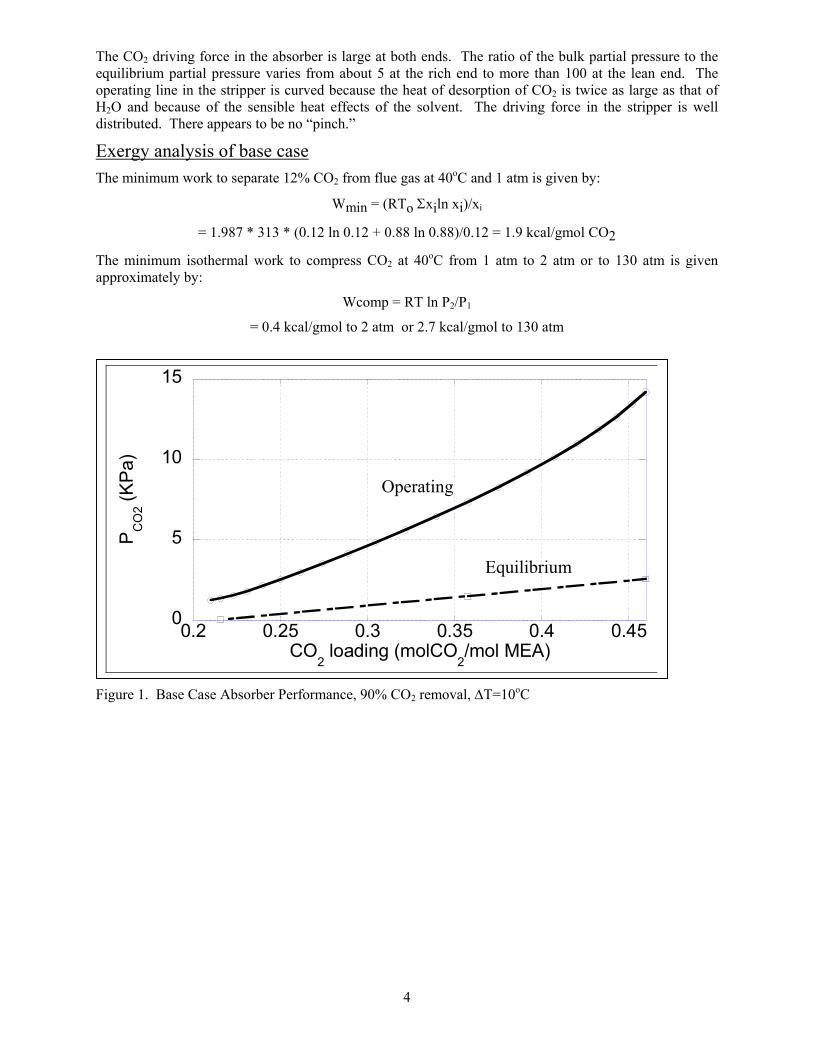
Figure 3 gives the stripper flowsheet for the simple stripper with a 5oC approach in the lean/rich exchanger. Because the sensible heat of the solvent plays less of a role in the stripper energy requirement, the optimum solvent rate is much higher, giving a capacity of only 0.11 mol CO2/mol MEA. At the lean loading of 0.36 mol CO2/mol MEA, the stripper is pinched at the rich end and the absorber driving force ratio (PCO2 – P*CO2) at the lean end is about the same as that in the rich end. The heat rate is reduced by 5% to 42 kcal/gmol CO2. The temperature in the bottom of the stripper is reduced to 117oC. Because the feed to the stripper will flash from 112oC to 107oC, the exchanger may need to be operated with a back pressure to avoid two phase flow and the resulting corrosion. The high lean loading in the bottom of the stripper may also cause corrosion and amine degradation in bottom of the stripper.
Table 1. Loss of Work in a simple MEA absorption/stripping process Basis Work
(kcal/mol CO2) Actual Steam 134oC 10.2 Compression 2–130 atm, 75% eff 3.9 Total 14.1 Ideal Compression 40oC, 1-130 atm 2.7 Separation 40oC, 12% CO2 1.9 Total 5.4 Lost Work Condenser 90oC – 40oC 2.7 Reboiler 130oC – 120oC 1.1 Exchanger 10∆oC 1.3 Absorber P/P* = 23 1.5 Compressor 3 stage, 75% 1.2 Total 8.2 Total Ideal Work + Lost Work 13.4
6
MultistageCompressor
W=3.9 kc/mol CO2
2 atm107 C
CO2130 atm
Q=42 kc/mol CO2
117 C
112 C
Simple Stripper∆T=5
Leanldg=0.36
Richldg=0.47
CoolingWater
CoolingWater
Figure 3. Simple stripper with 5oC approach in lean/rich exchanger.
Vapor Recompression
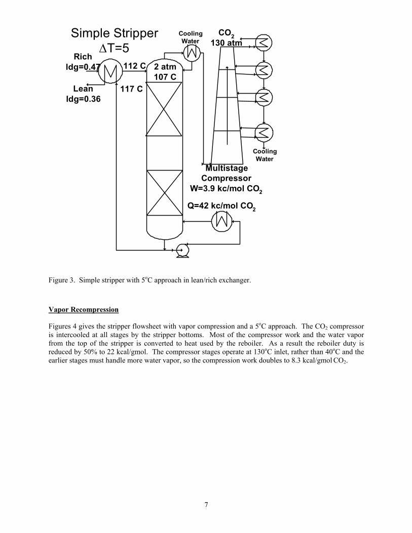
Figures 4 gives the stripper flowsheet with vapor compression and a 5oC approach. The CO2 compressor is intercooled at all stages by the stripper bottoms. Most of the compressor work and the water vapor from the top of the stripper is converted to heat used by the reboiler. As a result the reboiler duty is reduced by 50% to 22 kcal/gmol. The compressor stages operate at 130oC inlet, rather than 40oC and the earlier stages must handle more water vapor, so the compression work doubles to 8.3 kcal/gmol CO2.
7
MultistageCompressor
W=8.3 kc/mol CO2
2 atm107 C
CO2130 atm
Q=22 kc/mol CO2
117 C
112 C
Vapor Recompression
Leanldg=0.36
Richldg=0.47
117 C
Figure 4. Stripper with vapor recompression and 5oC approach
Multipressure Stripper
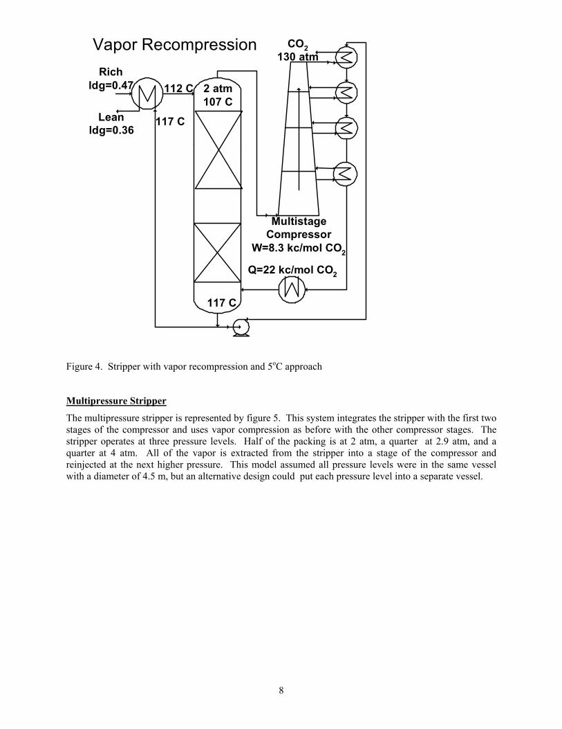
The multipressure stripper is represented by figure 5. This system integrates the stripper with the first two stages of the compressor and uses vapor compression as before with the other compressor stages. The stripper operates at three pressure levels. Half of the packing is at 2 atm, a quarter at 2.9 atm, and a quarter at 4 atm. All of the vapor is extracted from the stripper into a stage of the compressor and reinjected at the next higher pressure. This model assumed all pressure levels were in the same vessel with a diameter of 4.5 m, but an alternative design could put each pressure level into a separate vessel.
8
MultistageCompressor
W=7.2 kc/mol CO2
CO2130 atm
Q=22 kc/mol CO2
118 C
113 C
Multipressure Stripper
Leanldg=0.34
Richldg=0.46 115 C
4 atm
2.8 atm
2 atm
E-2
P-3
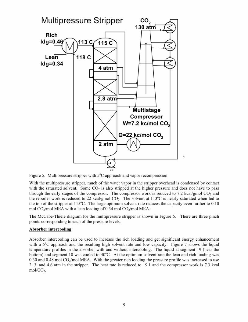
Figure 5. Multipressure stripper with 5oC approach and vapor recompression
With the multipressure stripper, much of the water vapor in the stripper overhead is condensed by contact with the saturated solvent. Some CO2 is also stripped at the higher pressure and does not have to pass through the early stages of the compressor. The compressor work is reduced to 7.2 kcal/gmol CO2 and the reboiler work is reduced to 22 kcal/gmol CO2. The solvent at 113oC is nearly saturated when fed to the top of the stripper at 115oC. The large optimum solvent rate reduces the capacity even further to 0.10 mol CO2/mol MEA with a lean loading of 0.34 mol CO2/mol MEA.
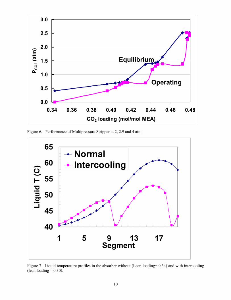
The McCabe-Thiele diagram for the multipressure stripper is shown in Figure 6. There are three pinch points corresponding to each of the pressure levels.
Absorber intercooling
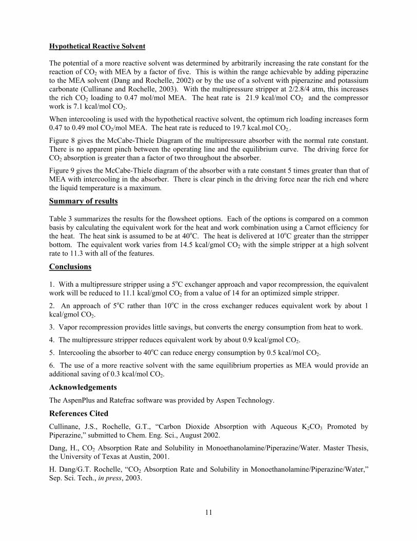
Absorber intercooling can be used to increase the rich loading and get significant energy enhancement with a 5oC approach and the resulting high solvent rate and low capacity. Figure 7 shows the liquid temperature profiles in the absorber with and without intercooling. The liquid at segment 19 (near the bottom) and segment 10 was cooled to 40oC. At the optimum solvent rate the lean and rich loading was 0.30 and 0.48 mol CO2/mol MEA. With the greater rich loading the pressure profile was increased to use 2, 3, and 4.6 atm in the stripper. The heat rate is reduced to 19.1 and the compressor work is 7.3 kcal mol/CO2.
9
0.0
0.5
1.0
1.5
2.0
2.5
3.0
0.34 0.36 0.38 0.40 0.42 0.44 0.46 0.48CO2 loading (mol/mol MEA)
P CO
2 (at
m)
Equilibrium
Operating
Figure 6. Performance of Multipressure Stripper at 2, 2.9 and 4 atm.
40
45
50
55
60
65
1 5 9 13 17Segment
Liqu
id T
(C)
NormalIntercooling
Figure 7. Liquid temperature profiles in the absorber without (Lean loading= 0.34) and with intercooling (lean loading = 0.30).
10
Hypothetical Reactive Solvent
The potential of a more reactive solvent was determined by arbitrarily increasing the rate constant for the reaction of CO2 with MEA by a factor of five. This is within the range achievable by adding piperazine to the MEA solvent (Dang and Rochelle, 2002) or by the use of a solvent with piperazine and potassium carbonate (Cullinane and Rochelle, 2003). With the multipressure stripper at 2/2.8/4 atm, this increases the rich CO2 loading to 0.47 mol/mol MEA. The heat rate is 21.9 kcal/mol CO2 and the compressor work is 7.1 kcal/mol CO2.
When intercooling is used with the hypothetical reactive solvent, the optimum rich loading increases form 0.47 to 0.49 mol CO2/mol MEA. The heat rate is reduced to 19.7 kcal.mol CO2..
Figure 8 gives the McCabe-Thiele Diagram of the multipressure absorber with the normal rate constant. There is no apparent pinch between the operating line and the equilibrium curve. The driving force for CO2 absorption is greater than a factor of two throughout the absorber.
Figure 9 gives the McCabe-Thiele diagram of the absorber with a rate constant 5 times greater than that of MEA with intercooling in the absorber. There is clear pinch in the driving force near the rich end where the liquid temperature is a maximum.
Summary of results
Table 3 summarizes the results for the flowsheet options. Each of the options is compared on a common basis by calculating the equivalent work for the heat and work combination using a Carnot efficiency for the heat. The heat sink is assumed to be at 40oC. The heat is delivered at 10oC greater than the strripper bottom. The equivalent work varies from 14.5 kcal/gmol CO2 with the simple stripper at a high solvent rate to 11.3 with all of the features.
Conclusions
1. With a multipressure stripper using a 5oC exchanger approach and vapor recompression, the equivalent work will be reduced to 11.1 kcal/gmol CO2 from a value of 14 for an optimized simple stripper.
2. An approach of 5oC rather than 10oC in the cross exchanger reduces equivalent work by about 1 kcal/gmol CO2.
3. Vapor recompression provides little savings, but converts the energy consumption from heat to work.
4. The multipressure stripper reduces equivalent work by about 0.9 kcal/gmol CO2.
5. Intercooling the absorber to 40oC can reduce energy consumption by 0.5 kcal/mol CO2.
6. The use of a more reactive solvent with the same equilibrium properties as MEA would provide an additional saving of 0.3 kcal/mol CO2.
Acknowledgements The AspenPlus and Ratefrac software was provided by Aspen Technology.
References Cited Cullinane, J.S., Rochelle, G.T., “Carbon Dioxide Absorption with Aqueous K2CO3 Promoted by Piperazine,” submitted to Chem. Eng. Sci., August 2002.
Dang, H., CO2 Absorption Rate and Solubility in Monoethanolamine/Piperazine/Water. Master Thesis, the University of Texas at Austin, 2001.
H. Dang/G.T. Rochelle, “CO2 Absorption Rate and Solubility in Monoethanolamine/Piperazine/Water,” Sep. Sci. Tech., in press, 2003.
11

EPA-600/2-75-006, January 1975
Freguia, S., G.T. Rochelle, G.T. “Modeling of CO2 Capture by Aqueous Monoethanolamine,” AIChE J., in press, 2003.
Freguia, S., Modeling of CO2 removal from Flue Gases with Monoethanolamine, M.S. Thesis, The Univerisity of Texas at Austin, 2002.
Hikita, H., Asai, S., Ishikawa, H., Honda, M., “The Kinetics of Reactions of Carbon Dioxide with Monoethanolamine, Diethanolamine and Triethanolamine by a Rapid Mixing Method”, Chem. Eng. J., 13, 7-12, 1977.
Jou., F.Y., Mather, A.E., Otto, F.D., “The Solubility of CO2 in a 30 Mass Percent Monoethanolamine Solution”, Can. J. Chem. Eng., 73, 140-147, 1995.
Pacheco, M.A., Mass Transfer, Kinetics and Rate-Based Modeling of Reactive Absorption. Ph.D. Dissertation, The University of Texas at Austin, 1998.
Weiland, R.H., “Physical Properties of MEA, DEA, MDEA and MDEA-Based Blends Loaded with CO2”, GRI/GPA Research Report RR-152. GPA project 911, 1996.
Table 3. Summary of Stripper Cases
lean rich capacity bottom top Qtotal Wtotal Wequiv Qcomp
Base Case, High suboptimum L/G 0.321 0.456 0.135 119.6 107.1 47.6 3.9 14.5 0.0 Low optimum L/G 0.213 0.459 0.246 123.7 109.6 44.0 3.9 14.0 0.0 + 5 C approach 0.356 0.467 0.111 117.0 107.4 42.0 3.9 13.0 0.0 + vapor recompression 0.356 0.467 0.111 117.0 107.4 21.9 8.3 13.0 -20.2 +2/2.8/4 atm stripper 0.342 0.464 0.122 118.0 114.8 22.2 7.2 12.1 -11.1 +2/3/4.6 atm, intercooling 0.302 0.481 0.179 120.5 116.5 19.1 7.3 11.6 -10.6 +k2=5k2MEA +2/2.8/4 atm 0.343 0.469 0.126 118.0 114.4 21.9 7.1 11.9 -11.0 +2/3.2/5 atm + Intercooling 0.316 0.492 0.176 119.8 115.8 19.7 6.9 11.3 -9.2
CO2 ldg (mol/mol MEA) Liquid T (oC) Energy (kcal/mol CO2)
12

0.00
0.02
0.04
0.06
0.08
0.10
0.12
0.35 0.37 0.39 0.41 0.43 0.45 0.47
CO2 Loading (mol/mol MEA)
YCO
2
Equilibrium
Operating
Figure 7. McCabe Thiele diagram for absorber without intercooling at normal rates, lean loading = 0.34.
0.00
0.02
0.04
0.06
0.08
0.10
0.12
0.34 0.36 0.38 0.40 0.42 0.44 0.46CO2 Loading (mol/mol MEA)
Y CO
2
Equilibrium
Operating
Figure 8. Absorber Performance with intercooling to 40oC and k2,amine = 5k2,MEA
13