innovative tubular, hoisting, and deepwater rig designs ... · innovative tubular, hoisting, and...
TRANSCRIPT
IADC/SPE151140
Innovative Tubular, Hoisting, and Deepwater Rig Designs
Extend Hook Load Envelope to 2,000,000 Pounds
J. N. Brock, R. B. Chandler, NOV Grant Prideco; C. Selen, Maersk Drilling USA; J. Dugas, W.
White, Quail Tools; M. Vasquez, A. Jonnalagadda, Statoil
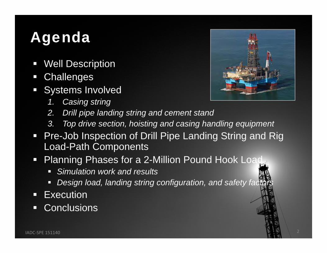
Well Description Challenges Systems Involved
1. Casing string2. Drill pipe landing string and cement stand3. Top drive section, hoisting and casing handling equipment
Pre-Job Inspection of Drill Pipe Landing String and Rig Load-Path Components
Planning Phases for a 2-Million Pound Hook Load Simulation work and results Design load, landing string configuration, and safety factors
Execution Conclusions
Agenda
IADC‐SPE 151140 2
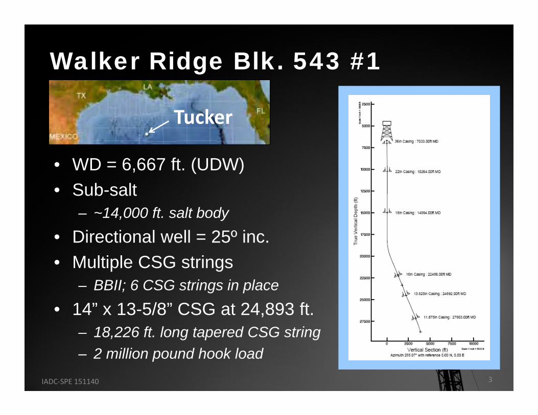
• WD = 6,667 ft. (UDW)• Sub-salt
– ~14,000 ft. salt body
• Directional well = 25º inc.• Multiple CSG strings
– BBII; 6 CSG strings in place
• 14” x 13-5/8” CSG at 24,893 ft.– 18,226 ft. long tapered CSG string – 2 million pound hook load
Walker Ridge Blk. 543 #1
Tucker
IADC‐SPE 151140 3
• Safely Makeup and Run 18,226 ft. of 14” x 13-5/8” Tapered Casing String– Ensure drill pipe landing string meets or
exceeds load requirements– Ensure ALL hoisting and casing running
equipment meets or exceeds load requirements
Challenge
IADC‐SPE 151140 4
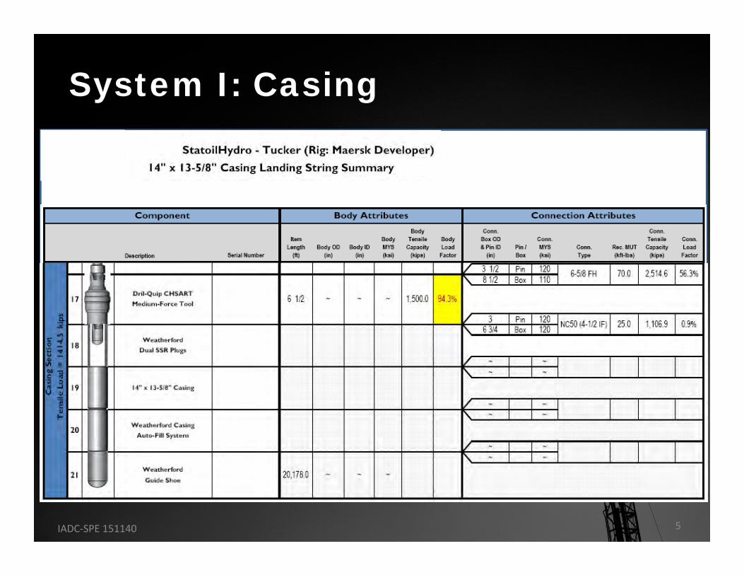
System I: Casing
IADC‐SPE 151140 5
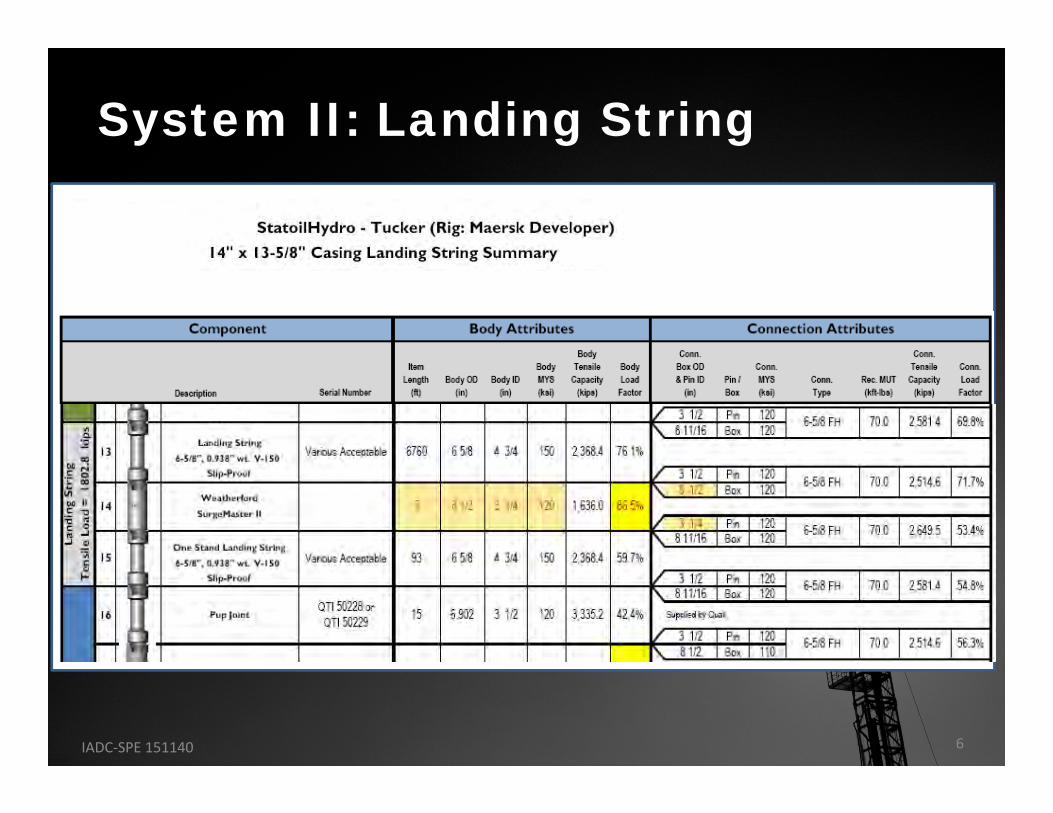
System II: Landing String
IADC‐SPE 151140 6
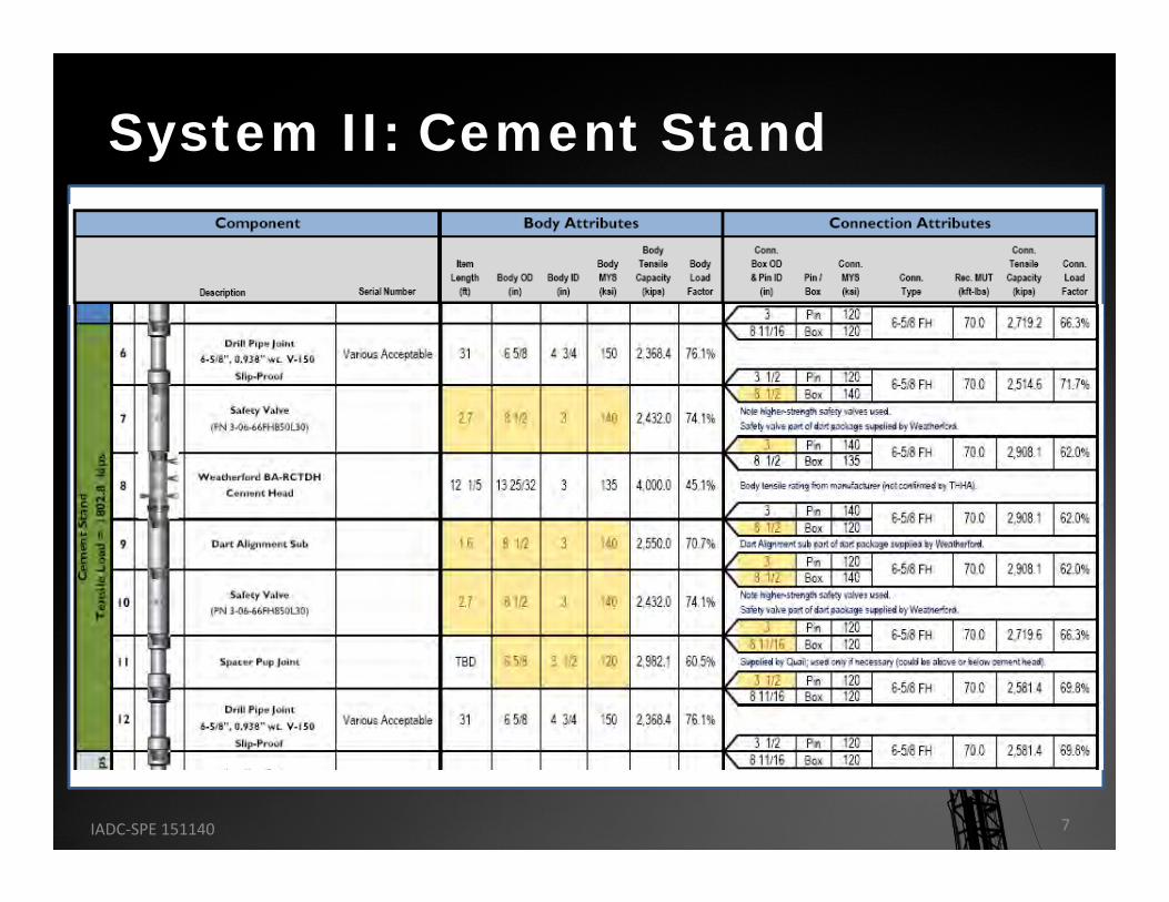
System II: Cement Stand
IADC‐SPE 151140 7
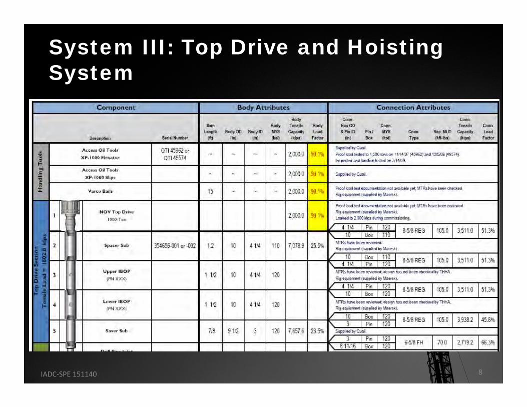
System III: Top Drive and Hoisting System
IADC‐SPE 151140 8
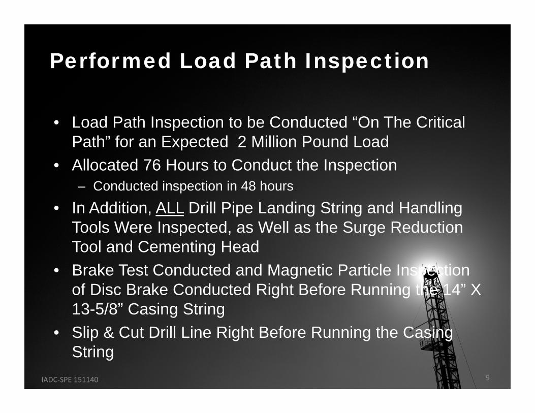
• Load Path Inspection to be Conducted “On The Critical Path” for an Expected 2 Million Pound Load
• Allocated 76 Hours to Conduct the Inspection – Conducted inspection in 48 hours
• In Addition, ALL Drill Pipe Landing String and Handling Tools Were Inspected, as Well as the Surge Reduction Tool and Cementing Head
• Brake Test Conducted and Magnetic Particle Inspection of Disc Brake Conducted Right Before Running the 14” X 13-5/8” Casing String
• Slip & Cut Drill Line Right Before Running the Casing String
Performed Load Path Inspection
IADC‐SPE 151140 9
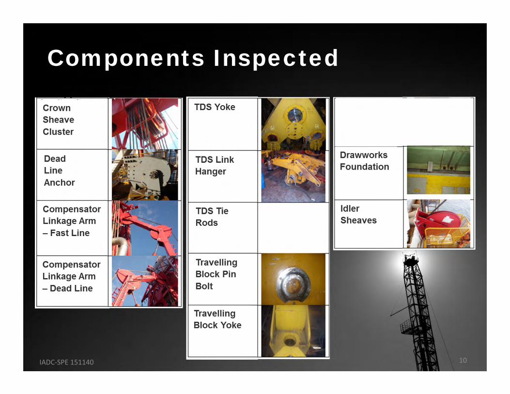
Components Inspected
IADC‐SPE 151140 10
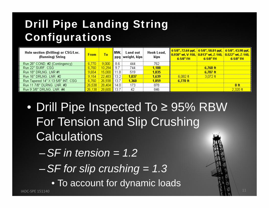
• Drill Pipe Inspected To ≥ 95% RBW For Tension and Slip Crushing Calculations– SF in tension = 1.2– SF for slip crushing = 1.3
• To account for dynamic loads
Drill Pipe Landing String Configurations
IADC‐SPE 151140 11
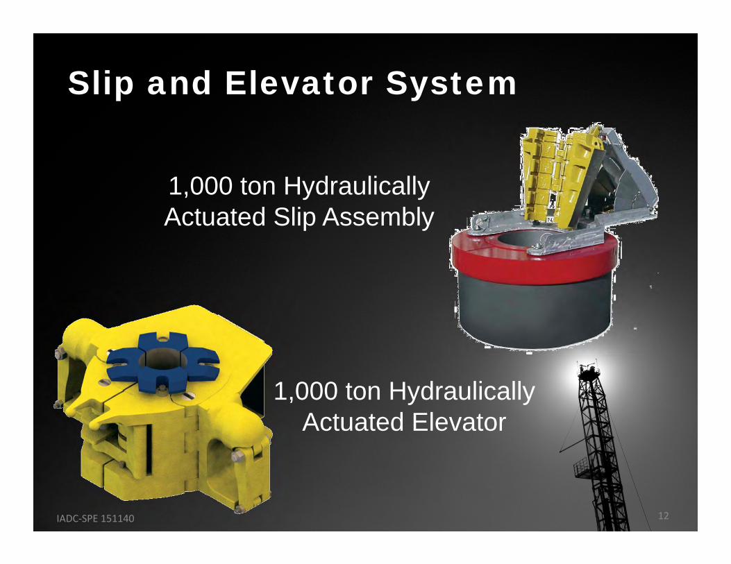
1,000 ton Hydraulically Actuated Slip Assembly
Slip and Elevator System
1,000 ton Hydraulically Actuated Elevator
IADC‐SPE 151140 12
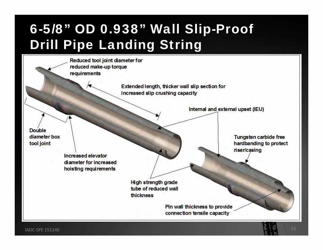
6-5/8” OD 0.938” Wall Slip-Proof Drill Pipe Landing String
IADC‐SPE 151140 13
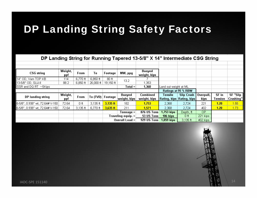
DP Landing String Safety Factors
IADC‐SPE 151140 14
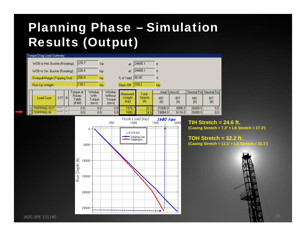
Planning Phase – Simulation Results (Output)
TIH Stretch = 24.6 ft.(Casing Stretch = 7.3’ + LS Stretch = 17.3’)
TOH Stretch = 32.2 ft.(Casing Stretch = 11.1’ + LS Stretch = 21.1’)
IADC‐SPE 151140 15
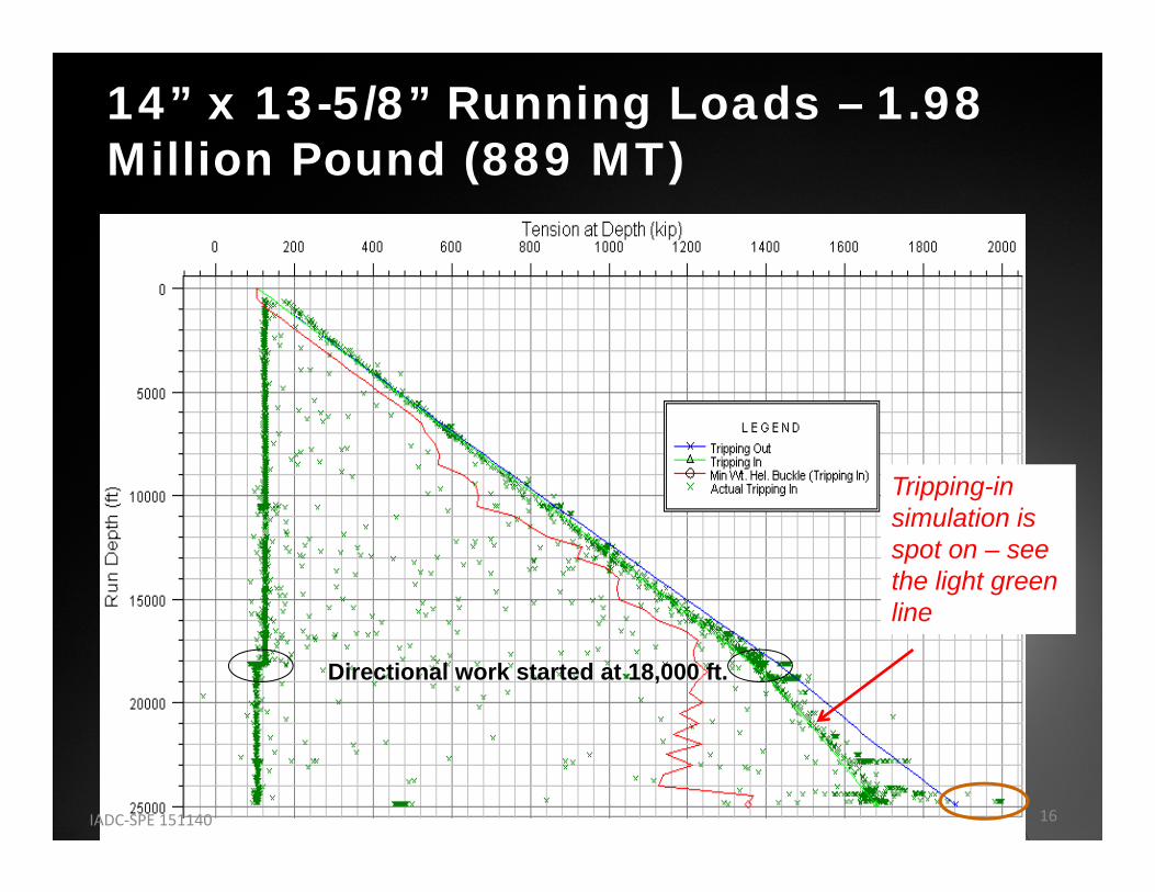
14” x 13-5/8” Running Loads – 1.98 Million Pound (889 MT)
Directional work started at 18,000 ft.
Tripping-in simulation is spot on – see the light green line
IADC‐SPE 151140 16
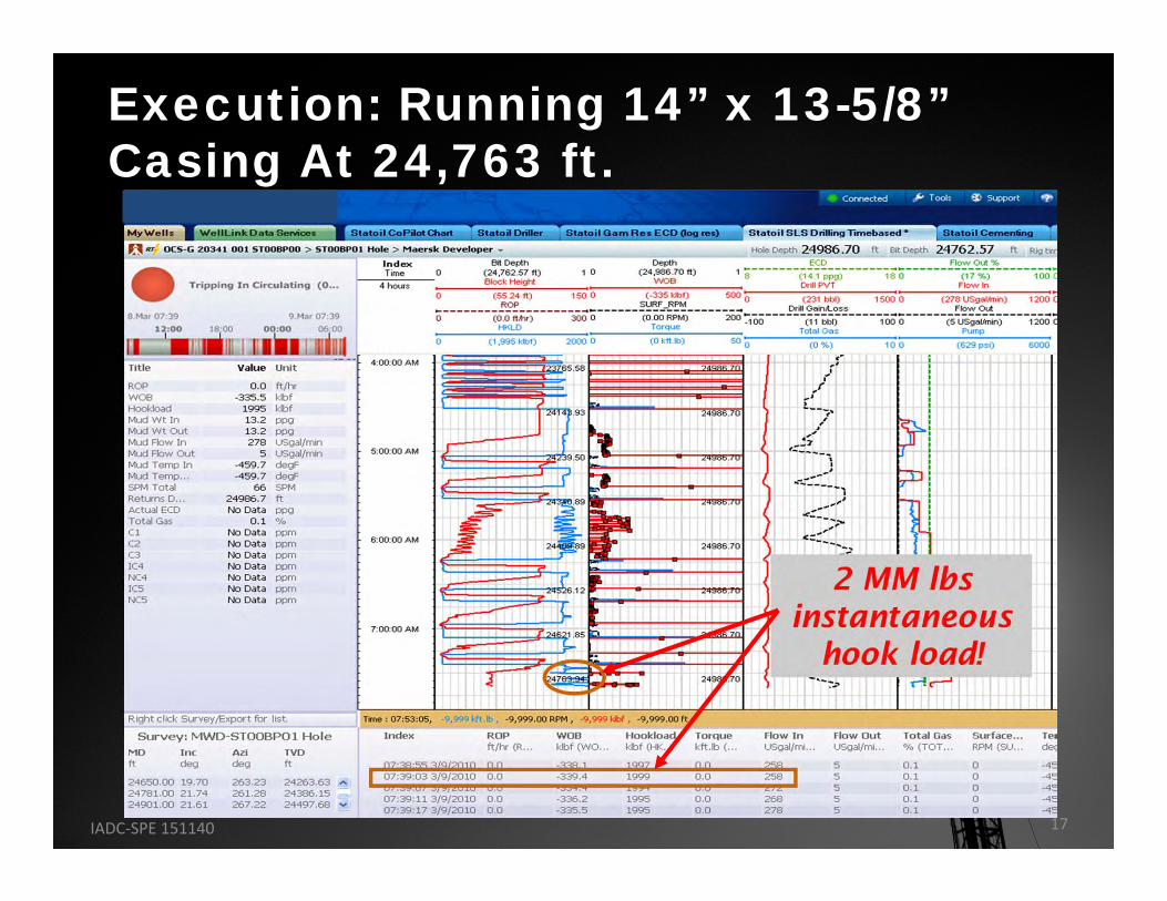
Execution: Running 14” x 13-5/8” Casing At 24,763 ft.
IADC‐SPE 151140 17
1. Tubular Technology Has Advanced Sufficiently to Make Possible the Safe Running of up to 2 MM lbf Hook Load Casing Strings
2. Attaining Greater Than 95% Wall Thickness Drill Pipe Landing String Is Possible
– Continue tracking of drill pipe wall thickness is critical in order to sort out joints in the landing string
Conclusions
IADC‐SPE 151140 18
3. Load-Path Inspection Is Critical to Ensure the Safety of the Operation
– Careful planning is required as this is done in the well program’s critical path prior to drilling this hole section
4. Tracking “Drag” During the Running of Casing Strings Allows the Forecast of Forces Associated with Heavy Casing String
– There Is a point (depth) of “no return” when running heavy casing strings
• The total of the string weight and drag prevent pulling the casing out of the hole
• Understanding this point by operations is “key” to the success or failure of landing the casing string, specifically if it comes earlier than expected
Conclusions
IADC‐SPE 151140 19
5. The Challenge Involved with Setting of Larger Diameter and Heavier Casing Strings with Total Setting Hook Loads Approaching 2 MM lbf has been met by Implementing a Total Systems Approach
6. On the First Well Drilled by the New MAERSK DEVELOPER, All Rig Equipment Performed as Designed and the Crews Demonstrated Their Competency by Successfully Managing the World Record Casing Setting Operation
Conclusions
IADC‐SPE 151140 20
Thank You
The authors wish to thank the management of Statoil ASA, Maersk Drilling USA, Inc.,
Quail Tools, and NOV Grant Prideco for their support and encouragement in publishing
this paper.