ins tall ation & owner’s - surplus...
TRANSCRIPT
&&
P-K SONIC® / NURO® GAS FIRED BOILER
SC-1500/SC-2000
SC-3000/SC-4000
Natural Gas/Propane/Dual Fuel
Part # 1004905978
C.S.A Design-Certified
Complies with ANSI Z21.13/CSA 4.9
Gas-Fired Low Pressure Steam and Hot Water Boilers
ASME Code, Section IV Certified by Patterson-Kelley
C.S.A Design-Certified
Complies with ANSI Z21.13/CSA 4.9 Gas-Fired Low Pressure Steam and Hot Water Boilers
Model Number: Serial Number:
Start-Up Date:
Harsco Industrial, Patterson-Kelley
155 Burson Street
East Stroudsburg, PA 18301
Telephone: 570.476.7261
Toll Free: 877.728.5351
Fax: 570.476.7247 www.harscopk.com
Revised August 1, 2015
INSTALLATION & O W N E R’S
MANUAL INSTALLATION
& O W N E R’S MANUAL
INSTALLATION & O W N E R’S
MANUAL INSTALLATION
& O W N E R’S MANUAL
INSTALLATION & O W N E R’S
MANUAL INSTALLATION
& O W N E R’S MANUAL
INSTALLATION & O W N E R’S
MANUAL INSTALLATION
& O W N E R’S MANUAL
HARSCO Industrial, Patterson-Kelley 2015: All Rights Reserved.
The information in this manual is the property of Harsco Industrial Patterson-Kelley. The descriptions and specifications contained in this manual were in effect at the time this manual was approved for publication. While Harsco Industrial Patterson-Kelley will continue to support earlier model boilers to within a reasonable time limit, we reserve the right to discontinue models and replacement parts at any time or change specifications or design without
notice and without incurring any obligation.

P-K SONIC TM Gas Fired Boiler
TTTTechnical Service 1.877.728.5351echnical Service 1.877.728.5351echnical Service 1.877.728.5351echnical Service 1.877.728.5351
Safety General
P-K SONIC TM SC-1500, SC-2000, SC-3000 and SC-4000
All P-K SONIC TM SC-1500, SC-2000, SC-3000 and SC-4000
Gas-Fired Boilers must be: • Installed, operated, and serviced in accordance with
instructions contained in this manual and other supplemental manuals.
• Installed by qualified personnel in accordance with designs prepared by qualified facility engineers including: structural, mechanical, electrical, and other applicable disciplines.
• Operated and serviced in accordance with a comprehensive safety program determined and established by the customer. Do not attempt to operate or service until such a program has been established.
• Operated and serviced by experienced, qualified, and properly trained personnel in accordance with all applicable codes, laws, and regulations.
Safety Precautions
Provide a suitable location for the boiler, away from normal personnel traffic, with adequate working space, adequate clearances, proper ventilation and lighting, with a structure sufficiently strong and rigid to support the weight of the boiler, all piping, and accessories.
NOTICE! Each safety device must be maintained and checked per the recommended schedule. Refer to Section 5 Maintenance.
SAFETY FEATURES It is the responsibility of the customer to ensure external safety provisions, such as but not limited to: guards, safety labels, safety controls, interlocks, lockout devices are in place and operable.
SAFETY LABELS The following words are used in this manual to denote the degree of seriousness of the individual hazards.
Indicates an imminently
hazardous situation which, if not avoided, will result in
death or serious injury. This signal word is to be limited
to the most extreme situations.
Indicates a potentially
hazardous situation which, if not avoided, could result in
death or serious injury.
Indicates a potentially
hazardous situation which, if not avoided, may result in
minor or moderate injury. It may also be used to alert against
unsafe practices.
NOTICE/NOTE - NOTICE Is the preferred signal word to address practices not related to personal injury. The safety alert symbol is not used with this signal word.

P-K SONIC TM Gas Fired Boiler
TTTTechnical Service 1.877.728.5351echnical Service 1.877.728.5351echnical Service 1.877.728.5351echnical Service 1.877.728.5351
NOTICE!
The safety labels shown below are affixed to your boiler. Although the labels are of high quality, they may become dislodged or unreadable over time. Contact Harsco Industrial, Patterson-Kelley at 570.476.7261 or toll-free at 877.728.5351 for replacements.
Gas may lose its odor. Proper gas sensing equipment and procedures
should be used for leak checks. Failure to detect gas leaks could
result in injury or death.
Training
Proper training is the best protection against accidents. It is essential to read, understand, and follow the recommendations of this manual before installing, operating, or servicing this equipment. Failure to do so could result in fire or explosion and serious injury, death, and/or property damage.
Operating and service personnel must be thoroughly familiar with the basic construction of the SC-1500, SC-2000, SC-3000 and SC-4000 boilers, the use and locations of the controls, the operation of the boilers, adjustment of their various mechanisms, and all applicable safety precautions. If any of the provisions of this manual are not fully and completely understood, contact Harsco Industrial, Patterson-Kelley Technical Service at 570.476.7261 or toll free at 877.728.5351.
Hazard Warnings
Electrical Hazards
Shock Hazard! Properly lockout/tagout the electrical service and all other energy sources before working on or near the boiler.
Shock Hazard! Do not spray water directly on this boiler or any electrical components.
Electrical Hazard! Do not alter wiring connections.
Crush Hazards
Lifting Hazards! Use properly rated lifting equipment to lift and position the boiler. The load is unbalanced. Test the balance before lifting off the floor. Do not allow personnel beneath the lifted load. Refer to the approximate weights in the table.
Boiler Model Boiler Size Weight in Pounds
SC-1500 1,500,000 BTU 1,450 lbs
SC-2000 2,000,000 BTU 1,450 lbs
SC-3000 3,000,000 BTU 1,850 lbs
SC-4000 4,000,000 BTU 1,900 lbs
Bump Hazard from Overhead Ductwork and Piping
Injury Hazard! Install components with adequate vertical clearance.
Pressure Hazards
Pressure Hazard! Hot fluids. Install isolation valves on boiler water inlet and outlet. Make sure isolation valves are closed before servicing boiler.
Pressure Hazard! Hot fluids. Annually test safety relief valve(s) for proper operation. Do not operate boiler with faulty relief valve(s).
P-K SONIC TM Gas Fired Boiler
TTTTechnical Service 1.877.728.5351echnical Service 1.877.728.5351echnical Service 1.877.728.5351echnical Service 1.877.728.5351
Slip, Fall Hazards
Tripping Hazard! Do not install piping on floor surfaces. Maintain a clear path around the boiler.
Slip and Fall Hazard! Use a drip pan to catch water while draining the boiler. Maintain dry floor surfaces.
Slip and Fall Hazard! Do not locate intake or exhaust terminations above a walkway; dripping of condensate can cause icing of the walking surface. Refer to Section 2.4.6.
Fall Hazard! Do not stand on boiler.
Chemical Hazards
Chemical Hazards from Cleaning Products. Use caution when cleaning the system. The use of professional assistance is recommended. Use safe procedures for the disposal of all cleaning solutions.
Combustion Condensate – An acidic pH of approximately 3.0 to 5.0 can be expected. Use PVC, CPVC, or other corrosion resistant piping for
drainage. Collection and disposal must be in accordance with all applicable regulations. A condensate neutralization kit is available. Please contact your local Harsco Industrial, Patterson-Kelley representative for more information.
Burn, Fire and Explosion Hazards
Burn, fire, and explosion hazards! Installation must be in strict conformance to all applicable
codes and standards including NFPA 54, ANSI Z223.1 and CAN/CSA B.149. Install all required vent
lines for gas devices. Refer to Section 3.3 and Section 3.4.
Hazard from Incorrect Fuels! Possible fire, explosion, overheating, and damage. Do not use any fuels except the design fuels for the unit.
Overfire Hazards! High pressure in gas supply could result in overfiring of this or other devices supplied from the same source.
Fire and Explosion Hazards! Close the main gas shutoff before servicing boiler.
Fire and Explosion Hazards! Do not store or use gasoline or other flammable vapors or liquids in the vicinity of this or any other gas fired appliance.
Burn hazard! Possible hot surfaces. Do not touch gas vent during firing operation. Use only factory recommended vent components.
Burn Hazard! Pipes, vents, and boiler components could be hot. Do not touch piping or stack surfaces during operation or immediately after shutdown of the boiler.
Burn Hazard! Hot flue! Use caution when servicing or draining boiler.
Fire and Explosion Hazards! Use caution when servicing burner. Propane (LPG) is heavier than air and may linger in the combustion chamber, vent lines, or elsewhere.
Gas Leak Hazard! Make sure the burner is installed correctly and blower/transition is securely fastened following any maintenance performed on them. These connections may leak gas if assembled incorrectly.
Gas Leak Hazard! All threaded gas connections must be made using a pipe compound that is resistant to liquefied petroleum gas. Do not use Teflon™ tape on threaded gas piping.
Gas Leak Hazard! Check entire gas train for leaks after installation. If there is a smell of gas, shut down the boiler and obtain immediate assistance from trained service personnel and/or your local fire department.
Overfire Hazard! Possible fire and explosion from excess gas pressure. Make sure that gas inlet pressure does not exceed 14 inches W.C.
Overfire Hazard! Possible fire and explosion. Possible malfunction of regulators and/or gas safety shut off/control valves. Maintain all gas train components in good condition. Do not alter wiring connections. Annual inspection by factory-trained personnel for proper set-up and operation is recommended.
Overfire and Underfire Hazards! Possible fire, explosion, overheating, and component failure. Do not attempt to adjust firing rate of the boiler. The firing rate must be adjusted only by factory trained personnel.

P-K SONIC TM Gas Fired Boiler
TTTTechnical Service 1.877.728.5351echnical Service 1.877.728.5351echnical Service 1.877.728.5351echnical Service 1.877.728.5351
Table of Contents DOCUMENT REVIEW AND ACCEPTANCE ................................... ERROR! BOOKMARK NOT DEFINED. REVISION HISTORY ................................................................ ERROR! BOOKMARK NOT DEFINED.
1 INTRODUCTION ..................................................... ERROR! BOOKMARK NOT DEFINED.
1.1 PURPOSE OF THIS DOCUMENT ....................................................................................... 5
1.2 USING THIS MANUAL ..................................................................................................... 5
1.3 HARSCO INDUSTRIAL, PATTERSON-KELLEY PRODUCT ABBREVIATIONS .......................... 5
2 SITE PREPARATION......................................................................................................... 6
2.1 RECEIVING AND STORAGE ............................................................................................. 6
2.1.1 Initial Inspection ...................................................................................................... 6
2.1.2 Storage Prior to Installation ..................................................................................... 6
2.2 COMPLIANCE WITH CODES ............................................................................................ 6
2.3 LOCATION SETUP ......................................................................................................... 7
2.3.1 Placement ............................................................................................................... 7
2.3.2 Clearances .............................................................................................................. 7
2.4 INLET AIR AND EXHAUST VENTING CONSIDERATIONS ....................................................... 8
2.4.1 Applicable Codes and Standards ............................................................................ 8
2.4.2 Gas Vent Category Planning ................................................................................... 9
2.4.3 Air Inlet Planning (United States and Canada Considerations) ................................ 9
2.4.4 Flue Venting Considerations ................................................................................... 9
2.4.5 Venting Materials for Flue/Exhaust Systems............................................................ 9
2.4.6 Required Clearances ............................................................................................ 10
2.4.6.1 Conventional Vent Systems Clearances ........................................................ 10
2.4.6.2 Direct Vent (Sealed Combustion) Systems Clearances ................................. 10
2.4.6.3 Interior Component Clearances ..................................................................... 11
2.4.6.4 Flue Connection ............................................................................................ 11
2.5 GAS PIPING CONSIDERATIONS .................................................................................... 11
2.6 WATER QUALITY STANDARD ........................................................................................ 11
3 INSTALLATION ............................................................................................................... 12
3.1 OVERVIEW ................................................................................................................. 12
3.2 ELECTRICAL CONNECTIONS ........................................................................................ 12
3.2.1 Power Requirements (CM300-CM399-CM500) ..................................................... 12
3.2.2 Single Phase Power Supply Connection (SC-1500 and SC-2000 Only) ................ 13
3.2.3 Three Phase Power Supply Connection (SC-3000 & SC-4000 Only) .................... 14
3.2.4 High Voltage (TB2) Terminal Block ........................................................................ 15
3.2.5 Low Voltage (TB1) Terminal Block ......................................................................... 16
3.3 COMBUSTION AIR ........................................................................................................ 17
3.3.1 Air Inlet Requirements ........................................................................................... 18
3.3.1.1 United States Considerations ........................................................................ 18
3.3.1.2 US Requirements .......................................................................................... 18
3.3.1.3 Canadian Considerations .............................................................................. 19
3.3.2 Flue Venting Installation ........................................................................................ 20
3.3.2.1 Vent Sizing .................................................................................................... 20
3.4 VENT TERMINATION ..................................................................................................... 21
3.4.1 Venting for Multiple Boilers .................................................................................... 22
3.4.2 Sealed Combustion/Direct Vent Systems .............................................................. 22
3.4.3 Inlet Duct Connection to Boiler .............................................................................. 23
3.4.4 Intake Duct Materials and Sizes ............................................................................ 23
P-K SONIC TM Gas Fired Boiler
TTTTechnical Service 1.877.728.5351echnical Service 1.877.728.5351echnical Service 1.877.728.5351echnical Service 1.877.728.5351
3.4.5 Category II Installations ......................................................................................... 23
3.4.6 Category IV Installations ....................................................................................... 25
3.4.7 Stainless Steel Venting ......................................................................................... 25
3.4.8 CPVC Vent System Installation ............................................................................. 25
3.5 REMOVING AN EXISTING BOILER .................................................................................. 26
3.6 PIPING ....................................................................................................................... 27
3.6.1 Gas Piping Overview............................................................................................. 27
3.6.2 Gas Supply Piping for Installer ............................................................................... 27
3.7 BOILER WATER PIPING ............................................................................................... 28
3.7.1 Boiler Inlet and Outlet Connections ....................................................................... 28
3.7.2 Boiler Water Piping (for Installer) .......................................................................... 28
3.7.2.1 Strainer ......................................................................................................... 28
3.7.2.2 Relief Valve Piping ........................................................................................ 29
3.7.2.3 Low Water Cut-Off ......................................................................................... 29
3.7.2.4 Drain Valve and Piping .................................................................................. 29
3.7.2.5 Condensate Drain ......................................................................................... 29
3.8 WATER QUALITY ......................................................................................................... 29
3.9 PRE-START CHECKLIST .............................................................................................. 30
3.10 SAFETY CHECKS ........................................................................................................ 30
3.10.1 Ignition Safety System Test ............................................................................... 31
3.10.2 Low Water Cut-out Test ..................................................................................... 31
3.10.3 Manual Reset High Temperature Limit Test ......................................................... 32
3.10.4 Gas Pressure Switch Tests ............................................................................... 32
3.10.4.1 Low Gas Pressure Switch .......................................................................... 32
3.10.4.2 High Gas Pressure Switch ......................................................................... 32
3.11 INITIAL NURO CONTROL SETUP AND ADJUSTMENT ...................................................... 33
3.11.1 Introduction ....................................................................................................... 33
3.11.2 Startup .............................................................................................................. 33
3.11.3 Home Screen .................................................................................................... 33
3.11.4 Information Screen ............................................................................................ 34
3.11.5 Comfort Heat Setup Wizard............................................................................... 34
3.11.5.1 Comfort Heat Operation ............................................................................ 35
3.12 FUEL/AIR ADJUSTMENTS ............................................................................................. 35
3.12.1 Gas Pressure Adjustment ................................................................................. 35
3.12.2 Combustion Setup and Adjustment .................................................................... 36
3.12.3 Adjusting High Fire ............................................................................................ 36
3.12.4 Adjusting Low Fire ............................................................................................. 37
3.12.5 Checking Flame Signal ..................................................................................... 37
4 OPERATIONS .................................................................................................................. 38
4.1 NURO TOUCHSCREEN CONTROL SYSTEM ................................................................... 38
4.1.1 NURO Control Panel ............................................................................................. 38
4.1.2 NURO Touch Screen Interface ............................................................................. 38
4.1.3 Factory Tests ........................................................................................................ 38
4.2 NORMAL LIGHTING AND SHUT-DOWN PROCEDURES ...................................................... 39
4.2.1 Normal Lighting Procedures .................................................................................. 39
4.2.2 Normal Shut Down Procedures ............................................................................. 39
4.3 EMERGENCY SHUT-OFF .............................................................................................. 39
4.4 TYPICAL BOILER OPERATING CONDITIONS ................................................................... 39
5 MAINTENANCE ............................................................................................................... 40

P-K SONIC TM Gas Fired Boiler
TTTTechnical Service 1.877.728.5351echnical Service 1.877.728.5351echnical Service 1.877.728.5351echnical Service 1.877.728.5351
5.1 MAINTENANCE AND INSPECTION SCHEDULE ................................................................. 40
5.1.1 Semi-Annually ....................................................................................................... 40
5.1.2 Annually ................................................................................................................ 40
5.2 PREVENTIVE MAINTENANCE ........................................................................................ 41
5.2.1 Daily Preventive Maintenance ............................................................................... 41
5.2.2 Weekly Preventive Maintenance ........................................................................... 41
5.2.3 Monthly Preventive Maintenance .......................................................................... 42
5.3 CLEANING THE BURNER & COMBUSTION CHAMBER ...................................................... 42
5.4 AFTER REPAIRS OR MAINTENANCE .............................................................................. 43
5.5 SEQUENCE OF OPERATIONS ........................................................................................ 44
5.6 TROUBLESHOOTING .................................................................................................... 45
5.6.1 Loss of Power ....................................................................................................... 45
5.6.2 Loss of Water Level .............................................................................................. 45
5.6.3 Low Gas Pressure................................................................................................. 45
5.6.4 High Gas Pressure ................................................................................................ 45
5.6.5 High Water Temperature ....................................................................................... 45
5.6.6 Low Air .................................................................................................................. 45
5.6.7 Flame Failure ........................................................................................................ 46
5.6.8 Flame Error ........................................................................................................... 46
5.6.9 Flue Problem ........................................................................................................ 46
6 PARTS/TECHNICAL SUPPORT ...................................................................................... 46
6.1 TERMINAL BLOCK ASSIGNMENTS AND WIRING DIAGRAMS ............................................. 47
6.1.1 Wiring Diagram – Power Box (SC-3000 and SC-4000 Only .................................. 47
6.1.2 Terminal Block Assignments — High Voltage (TB2) Terminal Block ...................... 48
6.1.3 Terminal Block Assignments — Low Voltage (TB1) Terminal Block ....................... 49
6.1.4 SC-3000 & SC-4000 Control Transformer Diagrams ............................................. 50
6.1.4.1 SC-3000 & SC-4000: 208 VAC, Three Phase, 60 Hertz ................................ 50
6.1.4.2 SC-3000 & SC-4000: 220-240 VAC, Three Phase, 60 Hertz ......................... 50
6.1.4.3 SC-3000 & SC-4000: 440-480 VAC, Three Phase, 60 Hertz ......................... 51
6.1.5 SC-1500 & SC-2000 Wiring Diagram .................................................................... 52
6.1.6 SC-3000 & SC-4000 480V Wiring Diagram ........................................................... 56
6.1.7 Main Boiler Assembly (SC-1500 & SC-2000) ........................................................ 58
6.1.8 NURO Control Panel (SC-1500 & SC-2000) ......................................................... 59
6.1.9 Heat Exchanger Assembly (SC-1500 & SC-2000) ................................................ 60
6.1.10 Natural Gas Train, Burner & Blower Assembly (SC-1500 & SC-2000) .............. 61
6.2 BOILER PARTS IDENTIFICATION (SC-3000 & SC-4000) ................................................. 62
6.2.1 Main Boiler Assembly (SC-3000 & SC-4000) ........................................................ 62
6.2.2 NURO Control Panel (SC-3000 & SC-4000) ......................................................... 63
6.2.3 Main Power Box (SC-3000 & SC-4000) ................................................................ 64
6.2.4 Heat Exchanger Assembly (SC-3000 & SC-4000) ................................................ 65
6.2.5 Natural Gas Train, Burner & Blower Assembly (SC-3000 & SC-4000) .................. 66
6.2.6 Propane Gas Train (SC-3000 & SC-4000) ............................................................ 67
7 LIMITED WARRANTY ..................................................................................................... 68
8 BOILER FIRE-TEST REPORT ......................................................................................... 69
APPENDIX A – MAINTENANCE LOG..................................................................................... 70
APPENDIX B – BOILER ALTITUDE DERATE SCHEDULE .................................................... 71
APPENDIX C – WATER QUALITY STANDARDS QUALITY STANDARDS FOR HYDRONIC BOILERS IN MULTI-METAL SYSTEMS ....................................................................................................... 72

P-K SONIC TM Gas Fired Boiler
TTTTechnical Service 1.877.728.5351echnical Service 1.877.728.5351echnical Service 1.877.728.5351echnical Service 1.877.728.5351
APPENDIX D – INSTALLATION AND QUICK REFERENCE .................................................. 73
FUEL/GAS SUPPLY ................................................................................................................. 73
ELECTRICAL/POWER SUPPLY .................................................................................................. 73
EXHAUST VENTING ................................................................................................................. 73
HYDRONICS/WATER FLOW (SC-1500 / SC-2000) .................................................................... 74
HYDRONICS/WATER FLOW (SC-3000 / SC-4000) .................................................................... 75

P-K SONIC TM Gas Fired Boiler
TTTTechnical Service 1.877.728.5351echnical Service 1.877.728.5351echnical Service 1.877.728.5351echnical Service 1.877.728.5351
1.1 Purpose of this Document
It is the purpose of this Installation and Owner’s Manual is to provide complete documentation support for P-K SONIC TM boilers featuring NURO controls. HARSCO Industrial, Patterson-Kelley is constantly seeking ways to produce high quality HVAC products. Our operation is based on the premium quality control program and insures that HARSCO Industrial manufactures quality products.
1.2 Using This Manual
The primary concern of all HARSCO Industrial, Patterson-Kelley equipment installation procedures is Safety. Following a title page Safety instructions and considerations are presented and repeated throughout the document as needed. If you have any questions on the information contained within, or do not fully and completely understand the content, please contact Harsco Industrial, Patterson-Kelley Technical Service at 570.476.7261 or toll free at 877.728.5351.
1.3 HARSCO Industrial, Patterson-Kelley Product Abbreviations
Abbreviation Description
AMP Ampere or Amperage
ANSI American National Standards Institute
ASME American Society of Mechanical Engineers
AWG American Wire Gauge
BTU British Thermal Unit
CH Comfort Heat
CO2 Carbon Dioxide
CSA Canadian Standards Association
CSD-1 Controls and Safety Devices
CPVC Chlorinated Polyvinyl Chloride
DHW Domestic Hot Water
ID Inside Diameter
MODBUS A serial communication protocol (not an abbreviation)
NFPA National Fire and Protection Agency
NTC Negative Temperature Coefficient
O2 Oxygen
OD Outside Diameter
OEM Original Equipment Manufacturer
SCFM Standard Cubic Feet per Minute
SMACNA Sheet Metal and Thermoplastic Duct Construction Manual Air Conditioning Contractors National Association
TB<#> Terminal Block (1, 2, 3 etc. depending on how many)
VAC Volts Alternating Current
VDC Volts Direct Current

P-K SONIC TM Gas Fired Boiler
TTTTechnical Service 1.877.728.5351echnical Service 1.877.728.5351echnical Service 1.877.728.5351echnical Service 1.877.728.5351
Installation and service must be
performed by a qualified installer, service agency, or gas
supplier. Failure to install the equipment in accordance with this manual could result in an unsafe operating condition.
NOTICE! Controls and other equipment that are damaged or fail due to weather exposure are not covered by warranty.
The boiler is heavy and
requires additional technicians to support and move the unit(s) during installation. Use extreme
caution to avoid dropping the boiler or cause any bodily
injury while lifting or handling. When positioning this boiler,
maintain positive control of it at all times. Do not attempt to move the boiler on surfaces that are not level. Failure to
heed this warning could result in personal injury or death.
NOTICE! The boiler may be installed on a combustible floor; however, the boiler must never be installed on carpeting.
Bumping hazard from overhead
ducts! Install all components with adequate vertical
clearances. Insufficient clearance can restrict the
service access, increasing the possibility of injury.
2 Site Preparation
2.1 Receiving and Storage
2.1.1 Initial Inspection
Upon receiving the boiler, inspect it for signs of shipping damage. Some damage may be hidden. Unpack the boiler, open the front and side doors and inspect the boiler. Verify that the total number of pieces shown on the packing slip agrees with those actually received.
2.1.2 Storage Prior to Installation
If the boiler is not installed immediately, it must be stored in a location adequately protected from the weather, preferably indoors. If this is not possible, then it should remain in the shipping container and be covered by a tarpaulin or other waterproof covering.
2.2 Compliance with Codes The boiler with standard components complies with American National Standard/CSA Standard ANSI Z21.13/CSA 4.9, latest edition, Gas-Fired Low Pressure Steam and Hot Water Boilers.
The P-K SONIC TM SC-1500, SC-2000, SC-3000 and SC-4000 heat exchangers are constructed and stamped in accordance with ASME Boiler and Pressure Vessel Code, Section IV.
Installation of the boiler must conform to all the requirements of all national, state and local codes established by the authorities having jurisdiction or, in the absence of such requirements, to the National Fuel Gas Code, ANSI Z223.1/NFPA 54 latest edition in the U.S. In Canada, the equipment shall be installed in accordance with the current Installation Code for Gas Burning Appliances and Equipment, CAN/CSA-B.149, latest edition, and applicable Provincial Regulations for the class, which should be carefully followed in all cases. Authorities having jurisdiction should be consulted before making any installation.
Where required by local codes, the installation must conform to American Society of Mechanical Engineers Safety Code for Controls and Safety Devices for Automatically Fired Boilers (ASME CSD-1).
In the Commonwealth of Massachusetts (a) this unit must be installed by a licensed pipe fitter/plumber, (b) field installed gas cocks must be “T” handle type, (c) piping of condensate shall conform to the State Plumbing Code, and (d) refer to the Massachusetts Supplement for further details.

P-K SONIC TM Gas Fired Boiler
TTTTechnical Service 1.877.728.5351echnical Service 1.877.728.5351echnical Service 1.877.728.5351echnical Service 1.877.728.5351
2.3 Location Setup
2.3.1 Placement
The boiler must be level to function properly. Six 9/16” holes in the base may be used for 3/8” anchor bolts.
1. Ensure the boiler is securely connected to the floor.
2. The boiler may be installed on a combustible floor (except carpeting) or a non-combustible surface such as a concrete housekeeping pad.
NOTE
Never install boiler on carpeting.
3. Once the boiler is situated, use a bubble level to make sure the boiler is completely level.
2.3.2 Clearances
If the boiler is to be installed near combustible surfaces, the inches minimum clearances are shown in the illustration below. Failure to provide adequate service clearances, even with non-combustible surfaces, may present problems during routine maintenance of the boiler. Maintain a clearance from the vent to combustible surfaces of 24” or as specified in the vent manufacturer’s listed installation instructions. The boiler must be installed in a space large in comparison to the boiler as described in the National Fuel Gas Code, NFPA 54/ANSI Z223.1, Latest Edition.
Type of Surface Dimensions (inches)
A B C† D
CSA Minimum Clearances to Combustibles 30 12* 24† 12**
Recommended Service Clearances 30 12* 24† 12**
* “B” Clearance depends upon exhaust vent configuration. † “C” Space required for pipes, ducts, etc. in this area above the boiler.
** Do not put pipes, ducts, vents, etc in this space. Electrical conduit must be installed vertically so that the side doors can be opened.
P-K SONIC TM Gas Fired Boiler
TTTTechnical Service 1.877.728.5351echnical Service 1.877.728.5351echnical Service 1.877.728.5351echnical Service 1.877.728.5351
Design and installation of
venting systems should be done only be qualified and
knowledgeable venting systems personnel and in accordance
with vent system manufacturer’s installation
instructions. Installing a boiler or vent system using improper
installation methods or materials can result in serious injury or death due to fire or
asphyxiation.
Before connecting a boiler to a
venting system, it must be determined whether the boiler
is to be installed in a conventional or direct vent
configuration. In the US, provisions for combustion air must be in accordance with
NFPA 54/ANSI Z223.1, National Fuel Gas Code, latest edition,
or applicable provisions of local building codes. In
Canada, combustion and ventilation air openings shall
comply with CAN/CSA B-149.1 Natural Gas and Propane
Installation Code.
For correct installation of vent system, read all of these
instructions and refer to vent manufacturer’s instructions.
Failure to use a proper vent system (types and materials),
as described in this manual will void the boiler warranty and
may result in rapid deterioration of the venting system, creating a health or life safety hazard. Faulty vent installation can
allow toxic fumes to be released into living areas. This may cause property damage,
injury or death.
2.4 Inlet Air and Exhaust Venting Considerations
2.4.1 Applicable Codes and Standards
United States: NFPA 54/ANSI Z223.1 National Fuel Gas Code
NFPA/ANSI 211 Chimneys, Fireplaces, Vents and Solid Fuel Burning Appliances
Canada:
CAN/CSA B149.1 Installation Codes for Gas Burning Equipment
Standards:
UL 1738 Venting Systems for Gas-Burning Appliances, Categories II, III and IV
ULC S636-95 Standard for Type BH Venting System Sheet Metal and Thermoplastic Duct Construction Manual Air Conditioning Contractors National Association (SMACNA)
These codes and standards contain information for the venting of gas fired appliances, including, but not limited to vent sizing, location, clearance to combustibles, and safe installation practices. The installation must comply with both the above Federal Codes and with state, provincial and local codes.
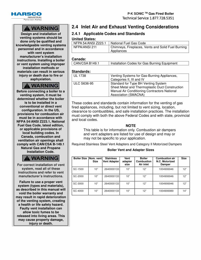
NOTE This table is for information only. Combustion air dampers and vent adapters are listed for use of design and may or may not be specific to your application.
Required Stainless Steel Vent Adapters and Category II Motorized Dampers
Boiler Vent and Adapter Sizes
Boiler Size Nom. vent Size
Stainless Vent Adapter
Vent adapter
size
Boiler Combustion
Air inlet
Combustion air N.C. Motorized
Damper
Size
SC-1500 10” 2640000133 10” 12” 1004906946 12”
SC-2000 10” 2640000133 10” 12” 1004906946 12”
SC-3000 10” 2640000133 10” 12” 1004906946 12”
SC-4000 10” 2640000133 10” 12” 1004906989 14”

P-K SONIC TM Gas Fired Boiler
TTTTechnical Service 1.877.728.5351echnical Service 1.877.728.5351echnical Service 1.877.728.5351echnical Service 1.877.728.5351
2.4.2 Gas Vent Category Planning
Several codes and standards have categorized appliances in accordance with the flue gas temperature and pressure produced by the appliance. The applicable categories are defined as follows:
• Category II: An appliance that operates with a non-positive vent static pressure and with a vent temperature that may cause excessive condensate production in the vent.
• Category IV: An appliance that operates with a positive vent static pressure and with a vent temperature that may cause excessive condensate production in the vent.
• Direct Vent: An appliance that is constructed and installed so that all air for combustion is derived directly from outdoors and all flue gases are discharged to the outdoors.
2.4.3 Air Inlet Planning (United States and Canada Considerations)
• Air inlet considerations for the United States are established by NFPA 54/ANSI Z223.1 & NFPA/ANSI 211.
• Air inlet requirements for the Canada States are established by CAN/CSA B149.1.
For details on the US air inlet requirements see Section 3.3.1 Air Inlet Requirements for more details.
2.4.4 Flue Venting Considerations
P-K SONIC TM boilers are dual certified as a Category II and Category IV appliances, as defined in ANSI Z21.13/CSA 4.9, latest edition. The vent material to be used for US and Canada is listed in the Table of Acceptable Materials for Venting Systems located in Section 2.4.5 Venting Materials for Flue/Exhaust Systems. The exhaust vent can be run horizontally or vertically.
Vent installations shall be in accordance with NFPA54/ANSI Z223.1, the National Fuel Gas Code, or CAN/CSA-B149.1, the Natural Gas and Propane Installation Code, or applicable provisions of the local building codes.
2.4.5 Venting Materials for Flue/Exhaust Systems
The P-K SONIC TM boilers are dual certified as a Category II and Category IV appliances, which vents with a temperature that is likely to cause condensation in the vent. Therefore, any venting system used with the P-K SONIC TM boiler must comply with the requirements for either Category II or Category IV venting systems as specified in the latest edition of NFPA 54/ANSI Z223.1 in the US or the latest edition of CAN/CSA B-149.1 in Canada.
CPVC Venting
US: CPVC pipe conforming to ASTM F441. Sch 80 fittings
conforming to ASTM F439. Joints are to be sealed with solvent
conforming ASTM 493.
Canada: CPVC Pipe, Fitting and Sealant listed and labeled to ULC S-636 Standard for Type BH Venting Systems.
Polypropylene Venting
US and Canada: Polypropylene such as InnoFlue from Centrotherm or PolyPro from DuraVent or other listed manufacturers. When used, the same manufacturer's material must be used throughout the system. It is not permissible to use material from different manufacturers within the same system.
The venting materials listed are intended for the venting of gas
burning appliances only. Do not use these venting materials for venting liquid or solid fuel
(such as oil, kerosene, wood or coal) appliances.
Maintain clearances to combustibles as listed in the
vent manufacturer’s installation instructions or as
set forth in the codes and standards listed in this section.
Do not use these vent pipes for incinerators of any sort!
This boiler is not certified for use with PVC venting. Use of
PVC venting may result in vent failure and possible serious
injury or death.

P-K SONIC TM Gas Fired Boiler
TTTTechnical Service 1.877.728.5351echnical Service 1.877.728.5351echnical Service 1.877.728.5351echnical Service 1.877.728.5351
As per ANSI Z21.13b-2012 * CSA 4.9b-2012:
• The use of cellular core PVC, CPVC and Radel as venting materials is prohibited.
• The use of external insulation on plastic vent pipe is prohibited.
Acceptable Venting Materials
Model Country AL29-4C 316L SS PVC CPVC POLYPROPYLENE
SC-1500 US Yes Yes No Yes Note 2
SC-2000 US Yes Yes No Yes Note 2
SC-3000 US Yes Yes No Yes Note 2
SC-4000 US Yes Yes No Yes Note 2
SC-1500 Canada Yes Yes No Note 1 Note 1
SC-2000 Canada Yes Yes No Note 1 Note 1
SC-3000 Canada Yes Yes No Note 1 Note 1
SC-4000 Canada Yes Yes No Note 1 Note 1
2.4.6 Required Clearances
2.4.6.1 Conventional Vent Systems Clearances
The following termination clearance requirements are for conventional non direct vent installations:
• The vent system shall terminate at least 3 ft. above a forced air inlet located within 10 ft. horizontally.
• The vent system shall terminate at least 4 ft . below, 4 ft. horizontally from or 1 ft. above any door, operable window or gravity inlet into any building. The bottom of the vent terminal shall be at least 12 in. above grade or highest expected snow line (if applicable).
• Through the wall terminations shall not terminate over public walkways or over an area where condensate or vapor could create a nuisance or hazard or could be detrimental to the operation of regulators, relief valves or other equipment.
2.4.6.2 Direct Vent (Sealed Combustion) Systems Clearances
• The vent terminal shall be located at least 12 in. from any air opening into a building. The bottom of the vent terminal shall be at least 12 in. above grade. Both the vent and air intake terminals must be at least 12 in. above the highest expected snow line.
• Through the wall terminations shall not terminate over public walkways or over an area where condensate or vapor could create a nuisance or hazard or could be detrimental to the operation of regulators, relief valves or other equipment.
• When multiple direct vent appliances are adjacent, the exhaust must terminate at least 10 ft. horizontally or 3 ft. vertically from the air intake of another appliance.
NOTE 1: When this material is used for venting, it must be listed to ULC-S636.
NOTE 2: When this material is
used for venting, it must be listed to UL-1738.

P-K SONIC TM Gas Fired Boiler
TTTTechnical Service 1.877.728.5351echnical Service 1.877.728.5351echnical Service 1.877.728.5351echnical Service 1.877.728.5351
2.4.6.3 Interior Component Clearances
All vent system components shall be installed so as to maintain the following required minimum clearances:
Material Combustible Non-Combustibles
Unlisted single wall metal pipe Do NOT Use Do NOT Use
Single wall PVC pipe Do NOT Use Do NOT Use
UL 1738 listed Category IV vent Per manufacturer’s listing Per manufacturer’s listing
Reference: NFPA 54/ANSI Z223.1 National Fuel Gas Code
The boiler vent should not be connected into any portion of
another mechanical draft system without consulting the vent
manufacturer. The boiler shall not be connected to any part of
a vent system serving a Category I appliance, nor shall a
Category I appliance be connected to any part of the
vent system serving this appliance. For Category II
common venting, refer to local venting codes. Improper
interconnection of venting systems may result in leakage of flue gases into occupied spaces.
NOTE
The condensate formed from combustion flue gases are acidic. The condensate shall be drained in accordance with local code. A condensate neutralizer may be required by local code.
2.4.6.4 Flue Connection The connection from the boiler to the vent should be as direct as possible and the upward slope of any horizontal breaching should be at least 1/4 inch per linear foot. The complete exhaust with drain system is Section 3.4 Vent Termination. The appliance connector should incorporate provisions to drain condensate formed in the vent system. The connector should include an appropriate drain section (not provided).
2.5 Gas Piping Considerations Before making the gas hook-up, make sure boiler is being supplied with the type of fuel shown on the boiler nameplate. The boiler shall be installed such that gas ignition system components are protected from water (dripping, spraying, rain, etc.) during appliance operation and service (circulator replacement, control adjustment, etc.).
2.6 Water Quality Standard The boiler’s heat exchanger is made of stainless steel. The heat exchanger requires proper water conditions to remain efficient and function properly. For information refer to Harsco Industrial, Patterson-Kelley Multi- Metal Systems Water Quality Standards in Appendix C, this applies to the warranty of your heat exchanger.
P-K SONIC TM Gas Fired Boiler
TTTTechnical Service 1.877.728.5351echnical Service 1.877.728.5351echnical Service 1.877.728.5351echnical Service 1.877.728.5351
3 Installation
3.1 Overview For site preparation follow the guidelines established in Section 2 Site Preparation. The information in this section will partially copy some of the information in that section as a reminder of how important site preparation is in the installation of the P-K SONIC TM boilers with NURO controls.
3.2 Electrical Connections
3.2.1 Power Requirements (CM300-CM399-CM500)
The SC-1500 and SC-2000 boiler requires 208-240 VAC, single phase, 60 hertz electrical service. The total operating amperage is indicated on the rating nameplate and the SC-1500 and SC-2000 requires less than 15 Amps at full load. Before starting the boiler, check to ensure that the proper electrical service is connected to the boiler.
The SC-3000 and SC-4000 boilers can be manufactured for 208-240 VAC, three phase, 60 hertz electrical service OR 440-480VAC, three phase, 60 hertz electrical service. The total operating amperage is indicated on the rating nameplate and the SC-3000 & SC-4000 boilers require less than 20 Amps at full load. Before starting the boiler, check to ensure that the proper electrical service is connected to the boiler.
NOTE
The SC-3000 & SC-4000 MUST be ordered to the correct voltage! IT IS NOT POSSIBLE to convert an SC-3000 or SC-4000 between the 240V and 480V
configurations in the field.
An external electrical disconnect and overload protection (not supplied with the boiler) are required. Refer to Section 6.1 for proper wiring and configuration of the electrical connections. The boiler electrical service must be installed and grounded in accordance with local codes or in the absence of such requirements, in the U.S. with National Electrical Codes, ANSI/NFPA No. 70 latest edition or, in Canada, to the current Canadian Electrical Code, Part I, CSA C22.1 latest edition. Installed conduit must not block any of the boiler’s openings and must allow the front door to be opened.

P-K SONIC TM Gas Fired Boiler
TTTTechnical Service 1.877.728.5351echnical Service 1.877.728.5351echnical Service 1.877.728.5351echnical Service 1.877.728.5351
3.2.2 Single Phase Power Supply Connection (SC-1500 and SC-2000 Only)
The SC-1500 and SC-2000 must be supplied with 208-240VAC, single phase, 60 hertz electrical service. The SC-1500 and SC-2000 feature four dedicated power terminals on the High Voltage (TB2) terminal block. The illustration below shows the Low Voltage (TB1) and High Voltage (TB2) terminal blocks on the SC-1500 and SC-2000 with the front door hidden for clarity:
• TB2 Terminal 1 = HOT L1
• TB2 Terminal 2 = HOT L2
• TB2 Terminal 3 = NEUTRAL
• TB2 Terminal 4 = GROUND
Do not over-tighten the terminal screws. Maximum tightening torque = 6 in-lbs!
NOTE
These terminals can accommodate maximum 10AWG wire.

P-K SONIC TM Gas Fired Boiler
TTTTechnical Service 1.877.728.5351echnical Service 1.877.728.5351echnical Service 1.877.728.5351echnical Service 1.877.728.5351
3.2.3 Three Phase Power Supply Connection (SC-3000 & SC-4000 Only)
Main Power Connection Box
Check the rating nameplate of the SC-3000 or SC-4000 boiler to determine the required electrical service:
• 208-240VAC, three phase, 60 hertz • 440-480VAC, three phase, 60 hertz
The incoming three phase power for the SC-3000 & SC-4000 boilers is connected to the over-current safety device (rated for 20 Amps) and the Ground terminal located in the main power connection box. The illustration below shows the Low Voltage (TB1) and High Voltage (TB2) terminal blocks, plus the Main Power Connection Box on the SC-3000 & SC-4000 with the front door hidden for clarity:
• Terminal 1 = HOT L1 • Terminal 3 = HOT L2 • Terminal 5 = HOT L3 • Terminal G = GROUND
The Main Power Connection Box features a Control Transformer which steps down two hot leads from the incoming three-phase power in order to supply 110-120VAC single phase power to the boiler’s control system. Be aware that SC-3000 & SC-4000 boilers ordered in the 240V configuration, are pre-wired from the factory for operation with 240 VAC three phase incoming power.
If 208 VAC three phase power is supplied to the boiler, the internal control transformer must be re-wired for operation at this lower voltage. The wire in terminal X3 on the load side of the internal control transformer must be moved to terminal X4. This supplies the 120 VAC power to the controls from the 208 VAC main voltage. Refer to Section 6.1 for proper wiring and configuration of the internal control transformer.
Do not over-tighten the hot lead terminal screws. Maximum tightening
torque = 13 in-lbs!
NOTE
The hot lead terminals can accommodate maximum 12AWG wire.
The ground terminal can accommodate maximum 8 AWG wire.

P-K SONIC TM Gas Fired Boiler
TTTTechnical Service 1.877.728.5351echnical Service 1.877.728.5351echnical Service 1.877.728.5351echnical Service 1.877.728.5351
Be sure to check the
nameplate on the boiler before connecting the
electrical supply.
NOTICE! A dedicated earth ground (green wire) is required to avoid nuisance shutdowns. Do not ground through the conduit!
The high voltage (TB2)
terminal block on the SONIC SC-1500 and SC-2000 with
NURO controls contains two hot leads (HOT L1 & HOT L2), a neutral lead (NEUTRAL) and a ground lead (GROUND) for 208- 240 VAC, single phase 60Hz electrical supply. This
terminal block (TB2) also contains dry-contact relays
with a maximum voltage rating of 240VAC and 1/2 Amp
maximum current capacity. Incorrect wiring can result in equipment damage, injury or
death.
The high voltage (TB2) terminal block on the SONIC
SC-3000 & SC-4000 with NURO controls contains dry-
contact relays with a maximum voltage rating of
240VAC and 1/2 Amp maximum current capacity.
Incorrect wiring can result in equipment damage, injury or
death.
3.2.4 High Voltage (TB2) Terminal Block
Start Interlock #2 – The Start Interlock #1 terminals can be used for auxiliary safety devices such as damper end limit switches, control valve end limit switches, emergency stop buttons, and low water cutoff devices. This circuit is energized with 120VAC, so the contacts on any auxiliary safety devices must be rated for a minimum of 120VAC.
Start Interlock #1 – The Start Interlock #2 terminals are in series with Start Interlock #1 and provide additional connection points for auxiliary safety devices. This circuit is energized with 120VAC, so the contacts on any auxiliary safety devices must be rated for minimum 120VAC.
The boiler ships with a factory-installed jumper across Start Interlock #1 and Start Interlock #2 terminals. Remove the jumper(s) if using any auxiliary safety devices.
NOTE Both the Start Interlock #1 and Start Interlock #2 circuits must close within 5 minutes of a call for heat. Failure to close the Start Interlock circuit will cause the boiler to lockout on alarm.
Auxiliary Input #2 – These terminals are reserved for future use. This circuit is energized with 120VAC.
Auxiliary Input #1 – These terminals are reserved for future use. This circuit is energized with 120VAC.
Air Damper Interlock – The Air Damper Interlock provides dedicated terminals for proof of open end limit switch on a motorized air damper. This circuit is energized with 120VAC, so the contacts on the end limit switch must be rated for minimum 120VAC.
The boiler ships with a factory-installed jumper across the Air Damper Interlock terminals. Remove the jumper if connecting a motorized air damper with end limit switch.
Relay A – User-configurable relay output #1. The normally-open contacts on this relay have a maximum voltage rating of 240VAC and maximum current capacity of 1/2 Amp.
Relay B – User-configurable relay output #2. The normally-open contacts on this relay have a maximum voltage rating of 240VAC and maximum current capacity of 1/2 Amp.
Relay C – User-configurable relay output #3. The normally-open contacts on this relay have a maximum voltage rating of 240VAC and maximum current capacity of 1/2 Amp.
Relay D – User-configurable relay output #4. The normally-open contacts on this relay have a maximum voltage rating of 240VAC and maximum current capacity of 1/2 Amp.

P-K SONIC TM Gas Fired Boiler
TTTTechnical Service 1.877.728.5351echnical Service 1.877.728.5351echnical Service 1.877.728.5351echnical Service 1.877.728.5351
NOTE
Refer to Section 6 Parts and Tech Support for proper wiring and configuration of the electrical connections.
Relays A thru D can be user-configured through the NURO touch screen interface to control devices such the Comfort Heat (CH) Pump, Domestic Hot Water (DHW) Pump, Air Damper, System Pump, etc.
Master Alarm Relay – The Master Alarm Relay terminals are normally-open dry contacts that close in the event of an alarm output from the boiler control.
3.2.5 Low Voltage (TB1) Terminal Block
Enable/Disable –TB1-1 and TB1-2 can be used to remotely enable or disable the boiler. The functionality of these terminals is user-configurable through the NURO controls, but generally closure of the Enable/Disable circuit provides a call for heat to the boiler. Opening this circuit prevents the boiler from running.
The boiler ships with a factory-installed jumper across the Enable/Disable terminals. This circuit is energized with a 24VAC potential, so the contacts on any remote enable devices must be rated for minimum 24VAC.
4-20mA Analog Input – TB1-3 and TB1-4 can be used to provide a remote analog 4-20mA control signal to the boiler. This analog signal can be used to change the boiler’s operating setpoint or firing rate.
Spare Analog Input – TB1-5 and TB1-6 are reserved for future use.
HDR Temp Sensor – TB1-7 and TB1-8 can be used to connect a remote header temperature sensor, installed in the primary hydronic system piping, downstream of all the boilers. This temperature sensor must be a 2-wire 12kΩ NTC thermistor. This circuit is energized by the boiler with a 5VDC potential.
DHW Stat/Sensor – TB1-9 and TB1-10 can be used to connect either an aquastat or remote DHW temperature sensor installed in a domestic hot water storage tank. If using an aquastat, use a SPST normally-closed, break on rise type with either a fixed or adjustable deadband above and below the setpoint.
Alternatively, if using a temperature sensor, it must be a 2-wire 12kΩ NTC thermistor and be of sufficient length to measure an accurate storage tank temperature. This circuit is energized by the boiler with a 5VDC potential.
Outdoor Temp Sensor – TB1-11 and TB1-12 can be used to connect an outdoor air temperature sensor which allows the NURO control to be programmed to run an outdoor air schedule. The outdoor air temperature sensor must be a 2-wire 12kΩ NTC thermistor and should be installed on the North face of the building and shielded from direct sunlight exposure. This circuit is energized by the boiler with a 5VDC potential.
Night Setback – TB1-13 and TB1-14 can be used to connect a day/night or occupancy timer. Closure of the Night Setback circuit enables the Night Setback mode which reduces the boiler’s operating setpoint. Opening this circuit resumes normal operation. This circuit is energized by the boiler with a 5VDC potential, so the contacts on the day/night timer must be rated for minimum 5VDC.
4-20mA Analog Output – TB1-15 and TB1-16 provide a 4-20mA analog output signal which tracks the boiler’s firing rate. When operating at full power (maximum firing rate), the boiler will provide a 20mA output. When operating at minimum power (minimum firing rate), the boiler will provide a 4mA output.
Ground – TB1-17 provides an equipment (frame) ground connection for input, output, or communication connections. For independently powered control devices, it may be necessary to create a common ground.

P-K SONIC TM Gas Fired Boiler
TTTTechnical Service 1.877.728.5351echnical Service 1.877.728.5351echnical Service 1.877.728.5351echnical Service 1.877.728.5351
Cascade Shield & Cascade – TB1-18, TB1-19 and TB1-20 can be used to setup a cascade system with multiple SONIC boilers with NURO controls. Terminals TB1-19 and TB1-20 are reserved for the cascade communication between the master and member boilers. Terminal TB1-18 should be used to connect the cascade communication wiring shield between all boilers. The cascade and shielding must be wired from the master boiler to each individual member boiler in a daisy-chain fashion. NOTE: Only ground the shield at the master boiler.
MODBUS COM & MODBUS Shield – TB1-22, TB1-23 and TB1-24 can be used to integrate the boiler with a Building Management System (BMS), Protocol Converter, or other device capable of RS-485 2-wire MODBUS communication. Terminals TB1-22 and TB1-23 are reserved for MODBUS and terminal TB1-18
provides a connection for the MODDBUS communication wire shield. NOTE: Only ground the shield at the master boiler.
ECOM 1, 2 & 3 – TB1-25, TB1-26 and TB1-27 can be used to connect a wireless outdoor air temperature sensor. The wireless receiver should be installed at or near the boiler, and the wireless temperature sensor should be installed on the North face of the building and shielded from direct sunlight exposure.
3.3 Combustion Air The air intake duct can be fabricated from PVC, CPVC, single wall galvanized steel, or other suitable materials. The duct must be rigid enough to maintain the full required cross sectional area under all operating conditions. Proper sealing of the intake ductwork is necessary to prevent infiltration of air from conditioned space. Joints in PVC or CPVC must be cemented. For galvanized duct, wrap each joint and seam with adhesive aluminum tape or other sealant. The installation of a bird screen on the intake termination is recommended. Ensure that the screen does not become blocked with snow, ice, insects etc. Combustion air duct should be designed with maximum 0.22” w.c. friction loss.
Combustion air must be free from dust, lint, etc. The presence of such materials in the air supplied to the burner could cause nuisance "Low Air" shutdowns or premature burner failure. The boiler should not be operated during construction while the possibility of drywall dust, demolition dust, etc. exists.
The combustion air supply must be completely free of chemical fumes which may be corrosive when burned in the boiler. Common chemicals which must be avoided are fluorocarbons and other halogenated compounds, most commonly present as refrigerants or solvents, such as Freon®, trichloroethylene, perchloroethylene, chlorine, etc. These chemicals, when burned, form acids which quickly attack the boiler and the boiler stack. The result is improper combustion and premature boiler failure.
Refer to the table below which summarizes the combustion air requirements for the SONIC boilers. Ensure the combustion air piping is of sufficient size (and acceptable equivalent length) in order to carry the required SCFM with a maximum friction loss of 0.22” W.C.
P-K SONIC™ Boiler Model
Required SCFM
SC-1500 350
SC-2000 467
SC-3000 629
SC-4000 839
Acceptable Materials for Venting Systems Manufactured Venting Systems US and Canada: AL29-4C Stainless Steel Vent Systems listed and labeled to UL1738 Venting Systems for Gas-Burning Appliances, Categories II, III, and IV 316L Stainless Steel where certified and warranted by the vent manufacturer for venting of Category II, III, or IV appliances

P-K SONIC TM Gas Fired Boiler
TTTTechnical Service 1.877.728.5351echnical Service 1.877.728.5351echnical Service 1.877.728.5351echnical Service 1.877.728.5351
3.3.1 Air Inlet Requirements
3.3.1.1 United States Considerations
When air is supplied from inside the building, the total required volume shall be the sum of the required volume for all the appliances located in the mechanical room. Adjacent rooms furnished with fixed openings communicating directly with the mechanical room are considered part of the required volume. The minimum
volume is 50 ft3 per 1000 Btu/hr (4.8 m3/kW) of installed appliance input capacity.
Openings used to connect indoor spaces to obtain the required minimum volume shall be sized as follows:
• When rooms are on the same floor, each opening shall have an area equal to 1 square inch for each 1000
Btu/hr (2200 mm2/kW) of installed appliance input capacity, but not less than 100 square inches. One opening should commence less than 12 inches above the floor and the other less than 12 inches below the ceiling. The minimum dimension of air openings shall be 3 inches.
• When rooms are on different floors, each opening shall have an area equal to 2 square inches for each
1000 Btu/hr (4400 mm2/kW) of installed appliance input capacity.
When combustion air is supplied from outside the building, the boiler room shall be provided with one or two openings to ensure adequate combustion air and proper ventilation.
When using one permanent opening, the opening shall commence within 12 inches of the ceiling and shall communicate directly with the outdoors or through a vertical or horizontal duct that communicates to the outdoors.
Minimum free area of the opening is 1 square inch for each 3000 Btu/hr (700 mm2/kW) of installed appliance input capacity, and not less than the sum of the areas of all vent connectors in the room.
Under no circumstances shall the boiler room ever
be under a negative pressure.
Particular care should be taken when exhaust fans, compressors, air-handling units or other equipment
may rob air from the boiler. Note that this equipment might be in rooms other
than the boiler room. This applies to both sealed
combustion and atmospheric room
combustion air applications.
3.3.1.2 US Requirements
Air inlet requirements for the United States are established by NFPA 54/ANSI Z223.1 & NFPA/ANSI 211. When using two permanent openings, one opening shall commence within 12 inches above the floor and the other within 12 inches below the ceiling, preferably on opposite walls. The openings shall communicate directly, or by way of ducts, with free outdoor air. The minimum net free area of the openings shall be calculated in accordance with the following:
• When air is taken directly from outside the building, each opening (minimum of two, as outlined above), 1 square inch for
each 4,000 Btu per hour (550 mm2/kW) of total boiler input is required.
• When air is taken from the outdoors through a vertical duct into the mechanical room, 1 square inch per 4,000 Btu per hour (550
mm2/kW) of total boiler input is required.
• When air is taken from the outdoors through a horizontal duct into the mechanical room, 1 square inch per 2,000 Btu per hour
(1100 mm2/kW) of total boiler input is required.

P-K SONIC TM Gas Fired Boiler
TTTTechnical Service 1.877.728.5351echnical Service 1.877.728.5351echnical Service 1.877.728.5351echnical Service 1.877.728.5351
US Minimum Area of Ventilation Openings per Boiler (Sq In)
SONIC TM Boiler MODEL
AIR SOURCE
INDOOR AIR SUPPLY OUTDOOR AIR SUPPLY
SAME FLOOR
DIFF FLOORS
ONE OPENING
TWO OPENINGS
DIRECT VERT DUCT
HORIZ DUCT
SC-1500 1500 3000 500 375 375 750
SC-2000 2000 4000 667 500 500 1000
SC-3000 3000 6000 1000 750 750 1500
SC-4000 4000 8000 1334 1000 1000 2000
3.3.1.3 Canadian Considerations
Air inlet requirements for the Canada States are established by CAN/CSA B149.1.
NOTE
1. The free area of a combustion air supply opening is calculated by deducting the blockage area of any fixed louvers, grilles or screens from the total area of the opening.
2. Screens shall be not smaller than ¼ inch.
3. Motorized louvers shall be interlocked with the appliance so that they are proven open prior to main burner ignition and operation.
A. A. Ventilation of the space occupied by fuel burning appliance(s) or equipment shall be supplied by a ventilation opening at the highest practicable point communicating with the outdoors. The total cross sectional area of the ventilation opening must be either 10% of the net free area required for
combustion air or 10 sq. in. (6500 mm2), whichever is greater.
B. Use the following opening calculation for P-K SONIC TM boilers:
When combustion air is supplied for a forced draft burner by natural airflow from the outdoors and there is no draft regulator or draft hood in the same space, there shall be a permanent opening with a
cross sectional area not less than 1 sq. in/30,000 Btu/Hr (70 mm2/kW) of the total rated input to the burner(s). This opening must not interfere with the ventilation air opening defined in paragraph A.
C. Use the following opening calculation for P-K THERMIFIC® boilers or other natural draft or fan-assist appliances:
When combustion air is supplied for natural or fan-assisted burners by natural airflow from the outdoors, there shall be a permanent opening with a cross sectional area not less than 1 sq. in/7000
Btu/Hr (321 mm2/kW) up to and including 1,000,000 Btu/Hr plus 1 sq. in./14,000 Btu/Hr (155 mm2/kW) in excess of 1,000,000 Btu/Hr. This opening must be either located at or ducted to a point not more than 18 in. (450 mm) or less than 6 in. (150 mm) above floor level. This opening is in addition to the ventilation air opening defined in paragraph A.
D. When combustion air is supplied by natural airflow into a space containing both types of appliance described in paragraphs B and C, the cross sectional area of the opening shall not be less than the sum of the cross sectional areas for all appliances in the space as calculated by the applicable method. This opening is in addition to the ventilation air opening defined in paragraph A.
E. When a duct is used to meet the requirement for combustion air supply, as described in paragraphs A through D, above, the opening of the duct shall be located so there is no possibility of cold air affecting steam or water piping, electrical equipment or mechanical equipment.

P-K SONIC TM Gas Fired Boiler
TTTTechnical Service 1.877.728.5351echnical Service 1.877.728.5351echnical Service 1.877.728.5351echnical Service 1.877.728.5351
F. When combustion air is supplied by mechanical means, an airflow-sensing device must be installed. It must be wired into the pre-ignition limit c to prevent the burner from starting or to stop an operating burner in case of air supply failure.
G. When all combustion air is supplied through a make-up air heater, and the appliance is interlocked to the heater, the requirements of paragraphs A through F do not apply.
Canadian Minimum Area of Combustion and Ventilation Air Openings
SONIC TM Boiler
BTU/Hr Required Combustion Air
Opening Ventilation Air Opening
Model # Input in2 mm2 in2 mm2
SC-1500 1,500,000 50 32,258 10 6,452
SC-2000 2,000,000 67 43,226 10 6,452
SC-3000 3,000,000 100 64,516 10 6,452
SC-4000 4,000,000 134 86,451 13.4 6,452
3.3.2 Flue Venting Installation
This boiler is not certified for use with Type "B" vent nor with PVC venting. All P-K SONIC TM boilers are dual certified as a Category II and Category IV appliances, as defined in ANSI Z21.13/CSA 4.9, latest edition. The vent material to be used for US and Canada is listed in the Table of Acceptable Materials for Venting Systems located in Section 2.4.5 Venting Materials for Flue/Exhaust Systems. The exhaust vent can be run horizontally or vertically.
Vent installations shall be in accordance with NFPA54/ANSI Z223.1, the National Fuel Gas Code, or CAN/ CSA-B149.1, the Natural Gas and Propane Installation Code, or applicable provisions of the local building codes.
3.3.2.1 Vent Sizing
The vent must be sized in accordance with the ASHRAE Systems and Equipment handbook, Chapter 30 or according to the vent manufacturer’s recommendations. When using manufactured venting systems, consult your vent supplier for correct sizing and structural support requirements. See the below table for vent design parameters
P-K SONIC™ Boiler Model Frictional Resistance Stack Temperature CO2 Natural Gas CO2 LP Gas
SC-1500, SC-2000, SC-3000, SC-4000
0.22” wc 220 °F 9.2% 10.4%

P-K SONIC TM Gas Fired Boiler
TTTTechnical Service 1.877.728.5351echnical Service 1.877.728.5351echnical Service 1.877.728.5351echnical Service 1.877.728.5351
3.4 Vent Termination For interior clearance requirements, refer to Section 2.4.6.3 Interior Component Clearances. The vent shall extend at least three (3) feet above the roof, or at least two (2) feet above the highest part of any structure within ten (10) feet of the vent. This is illustrated in the following diagram.
Additionally the boiler vent shall terminate at least 3 ft above a forced air inlet located within 10 ft.
To prevent the possible re-circulation of flue gases, the vent designer must take into consideration such things as prevailing winds, eddy zones, building configurations, etc. Harsco Industrial, Patterson-Kelley cannot be responsible for the effects such adverse conditions may have on the operation of the boilers.
Dimensions listed above are minimums and may not be sufficient for conditions at a specific job site.
Vertical vents are allowed to be terminated with a variety of ends, including plain straight pipe, elbow or vent tee. Horizontal vents must be terminated as illustrated in Section 3.4.2 Sealed Combustion/Direct Vent Systems. A bird screen with 1” x 1” openings is recommended for the termination. Harsco Industrial, Patterson- Kelley does not recommend using a vent rain cap of any type.
P-K SONIC TM Gas Fired Boiler
TTTTechnical Service 1.877.728.5351echnical Service 1.877.728.5351echnical Service 1.877.728.5351echnical Service 1.877.728.5351
3.4.1 Venting for Multiple Boilers
While the vent design parameters outlined in Section 3.3 Combustion Air and Section 3.4 Vent Termination still apply, achieving those same parameters in a combined vent system, adds a significant degree of complexity. Therefore, venting systems for multiple boilers shall be designed by experienced and knowledgeable venting professionals. The venting system shall be designed to prevent backflow of exhaust gas through idle boilers. For combined breeching installations, please follow recommendations of a qualified venting engineer/manufacturer.
RECOMMENDATION!
Harsco Industrial, Patterson-Kelley recommends that common venting systems be designed for a maximum continuous exhaust pressure of -0.04” W.C. when measured in the common vent. Locking inline dampers are recommended on the discharge of each boiler in order to maintain a slightly positive exhaust pressure within the boiler and upstream of the damper. The -0.04” W.C. in the common flue will help make sure the exhaust gases from an online boiler does not backflow through offline boiler(s). In addition, Harsco Industrial, Patterson-Kelley also recommends the use of motorized dampers in the combustion air intake duct to help prevent the backflow of flue gases from online boilers through offline boilers.
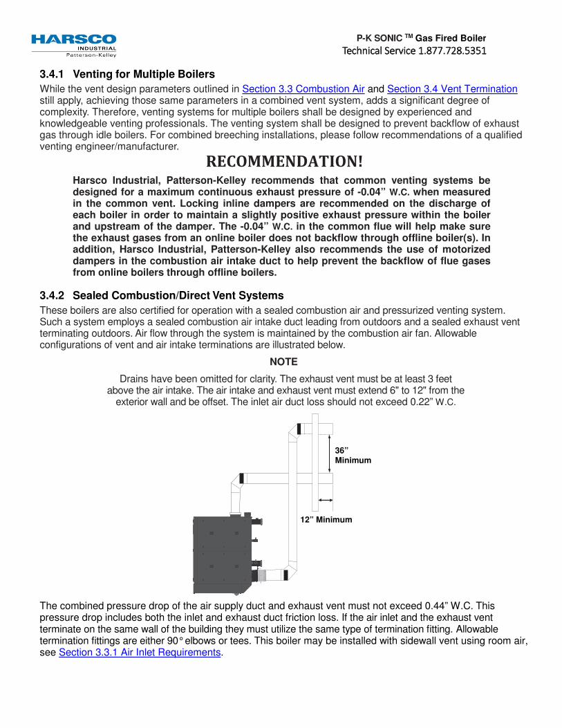
3.4.2 Sealed Combustion/Direct Vent Systems
These boilers are also certified for operation with a sealed combustion air and pressurized venting system. Such a system employs a sealed combustion air intake duct leading from outdoors and a sealed exhaust vent terminating outdoors. Air flow through the system is maintained by the combustion air fan. Allowable configurations of vent and air intake terminations are illustrated below.
NOTE
Drains have been omitted for clarity. The exhaust vent must be at least 3 feet above the air intake. The air intake and exhaust vent must extend 6" to 12" from the
exterior wall and be offset. The inlet air duct loss should not exceed 0.22” W.C.
The combined pressure drop of the air supply duct and exhaust vent must not exceed 0.44” W.C. This pressure drop includes both the inlet and exhaust duct friction loss. If the air inlet and the exhaust vent terminate on the same wall of the building they must utilize the same type of termination fitting. Allowable termination fittings are either 90° elbows or tees. This boiler may be installed with sidewall vent using room air, see Section 3.3.1 Air Inlet Requirements.
12” Minimum
36” Minimum

P-K SONIC TM Gas Fired Boiler
TTTTechnical Service 1.877.728.5351echnical Service 1.877.728.5351echnical Service 1.877.728.5351echnical Service 1.877.728.5351
3.4.3 Inlet Duct Connection to Boiler
Connect the air supply duct to the inlet air collar on the boiler. The air inlet collar is 11.875” OD. Fasten the air inlet duct to the collar with sheet metal screws at 90° angles and seal with aluminum tape or sealant.
3.4.4 Intake Duct Materials and Sizes
The air intake duct can be fabricated from PVC, CPVC, single wall galvanized steel, or other suitable materials. The duct must be rigid enough to maintain the full required cross sectional area under all operating conditions. Proper sealing of the intake ductwork is necessary to prevent infiltration of air from conditioned space. Joints in PVC or CPVC must be cemented. For galvanized duct, wrap each joint and seam with adhesive aluminum tape or other sealant. The installation of a birdscreen on the intake termination is recommended. Ensure that the screen does not become blocked with snow, ice, insects, etc.
3.4.5 Category II Installations
The SONIC boilers are dual-certified for either Category II or Category IV operation. Category II appliances operate with a non-positive vent static pressure and with a vent temperature that may cause excessive condensate production in the vent. There are several requirements for reliable operation of the boilers under Category II conditions:
1. A stainless steel vent adapter is required to mate the boiler exhaust connection and the vent pipe. See the table below for the applicable part numbers.
2. A normally-closed motorized damper is required on the boiler’s air intake. See the table below for the applicable part numbers.
3. The draft, measured inside the vent at the rear of the boiler, must not exceed -0.05” W.C. Excessive negative draft will cause nuisance trips such as flame failures.
4. The vent system must be properly drained of condensate before returning to the boiler. See Section 3.6.5.5 Condensate Drain for information on installing condensate drains in the exhaust vent.
Table of Required Stainless Steel Vent Adapters and Category II Motorized Dampers
Boiler Size
Nom. vent Size
Stainless Vent Adapter
Vent adapter size
Boiler Combustion Air inlet
Combustion air N.C. Motorized Damper
Size
SC-1500 10” 2640000133 10” 12” 1004906946 12”
SC-2000 10” 2640000133 10” 12” 1004906946 12”
SC-3000 10” 2640000133 10” 12” 1004906946 12”
SC-4000 10” 2640000133 10” 12” 1004906989 14”
A normally-closed motorized combustion air damper with end limit switch is required for Category II vent installations, and is optional for Category IV vent installations. 120VAC motorized dampers with end limit switches are available for purchase from Harsco Industrial, Patterson-Kelley. Other damper motor voltages are acceptable, provided they do not exceed 240VAC. The Air Damper Interlock circuit for the end limit switch is always 120VAC which is sourced from the boiler itself. All end limit switches must be rated for a minimum 120VAC.

P-K SONIC TM Gas Fired Boiler
TTTTechnical Service 1.877.728.5351echnical Service 1.877.728.5351echnical Service 1.877.728.5351echnical Service 1.877.728.5351
For correct installation of vent system, read all of these
instructions and refer to vent manufacturer’s instructions.
Failure to use a proper vent system (types and materials), as described in this manual will void the boiler warranty
and may result in rapid deterioration of the venting
system, creating a health or life safety hazard.
Faulty vent installation can allow toxic fumes to be
released into living areas. This may cause property damage,
injury or death.
Motorized dampers must be powered from an external power supply other than the boiler. The figure below shows a sample installation in which Relay C is user-selected to operate a 120VAC motorized air damper. Relay C is normally-open, so when the boiler is in standby, the combustion air damper remains closed. Once a call for heat is received, Relay C closes the 120VAC circuit (external power supply) which provides power to the damper motor, opening the damper. Once the motorized damper is fully-open, its end limit switch completes the Air Damper Interlock circuit (120VAC) which allows the boiler to proceed to ignition.
NOTE The NURO control allows the user to allocate Relay A, B or C for use with a motorized combustion air damper. The figure above shows Relay C in use for the motorized combustion air damper. Depending on the user-configuration, Relay A, Relay B, or Relay C can be selected to operate the combustion air damper.
External power supplies are required
for Relay A, Relay B and Relay C. Because power is provided from an external source, the power is still
present when the boiler is turned off. Check all voltage sources have been
disconnected prior to servicing. Failure to do so could result in electrocution, injury, or death.
NOTICE! Relay A, Relay B and Relay C are rated for a maximum voltage of 240VAC and a maximum current capacity of ½ Amp. Connecting a motorized damper which exceeds the voltage or current capacity of the relay could cause permanent damage to the relay.
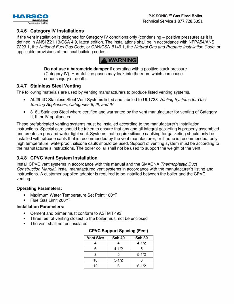
P-K SONIC TM Gas Fired Boiler
TTTTechnical Service 1.877.728.5351echnical Service 1.877.728.5351echnical Service 1.877.728.5351echnical Service 1.877.728.5351
3.4.6 Category IV Installations
If the vent installation is designed for Category IV conditions only (condensing – positive pressure) as it is defined in ANSI Z21.13/CSA 4.9, latest edition. The installations shall be in accordance with NFPA54/ANSI Z223.1, the National Fuel Gas Code, or CAN/CSA-B149.1, the Natural Gas and Propane Installation Code, or applicable provisions of the local building codes.
Do not use a barometric damper if operating with a positive stack pressure (Category IV). Harmful flue gases may leak into the room which can cause serious injury or death.
3.4.7 Stainless Steel Venting
The following materials are used by venting manufacturers to produce listed venting systems.
• AL29-4C Stainless Steel Vent Systems listed and labeled to UL1738 Venting Systems for Gas-Burning Appliances, Categories II, III, and IV
• 316L Stainless Steel where certified and warranted by the vent manufacturer for venting of Category II, III or IV appliances
These prefabricated venting systems must be installed according to the manufacturer’s installation instructions. Special care should be taken to ensure that any and all integral gasketing is properly assembled and creates a gas and water tight seal. Systems that require silicone caulking for gasketing should only be installed with silicone caulk that is recommended by the vent manufacturer, or if none is recommended, only high temperature, waterproof, silicone caulk should be used. Support of venting system must be according to the manufacturer’s instructions. The boiler collar shall not be used to support the weight of the vent.
3.4.8 CPVC Vent System Installation
Install CPVC vent systems in accordance with this manual and the SMACNA Thermoplastic Duct Construction Manual. Install manufactured vent systems in accordance with the manufacturer’s listing and instructions. A customer supplied adapter is required to be installed between the boiler and the CPVC venting. Operating Parameters:
• Maximum Water Temperature Set Point 180°F
• Flue Gas Limit 200°F
Installation Parameters:
• Cement and primer must conform to ASTM F493
• Three feet of venting closest to the boiler must not be enclosed
• The vent shall not be insulated
CPVC Support Spacing (Feet)
Vent Size Sch 40 Sch 80
4 4 4-1/2
6 4-1/2 5
8 5 5-1/2
10 5-1/2 6
12 6 6-1/2

P-K SONIC TM Gas Fired Boiler
TTTTechnical Service 1.877.728.5351echnical Service 1.877.728.5351echnical Service 1.877.728.5351echnical Service 1.877.728.5351
3.5 Removing an Existing Boiler
When an existing boiler is removed from a common venting system, the common venting system is likely to be too large for proper venting of the appliances remaining connected to it.
At the time of removal of an existing boiler, while the other appliances remaining connected to the common venting system are not in operation, the following steps should be followed with each appliance remaining connected to the common venting system placed in operation:
1. Seal any unused openings in the common venting system.
2. Visually inspect the venting system for proper size and horizontal pitch and determine that there is no blockage or restriction, leakage, corrosion or other deficiency which could cause an unsafe condition.
3. Insofar as is practical, close all building doors and windows and all doors between the space in which the appliance remaining connected to the common venting system are located and other spaces of the building. Turn on clothes dryers and any appliances not connected to the common venting system. Turn on any exhaust fans, such as range hoods and bathroom exhausts, so they will operate at maximum speed. Do not operate a summer exhaust fan. Close fireplace dampers.
4. Place the appliance being inspected in operation. Follow the lighting instructions. Adjust the thermostat so that the appliance will operate continuously.
5. Test for spillage at the draft hood relief opening after 5 minutes of main burner operation. Use the flame of a match or candle or smoke from a cigarette, cigar or pipe.
6. After it has been determined that each appliance remaining connected to the common venting system properly vents when tested as outlined above, return doors, windows, exhaust fans, fireplace dampers and any other gas-burning appliance to their previous conditions of use.
Any improper operation of the common venting system should be corrected so the installation conforms to the National Fuel Gas Code, ANSI Z223.1 and CSA B149 Installation Code. When resizing any portion of the common venting system, the common vent system should be resized to approach the minimum size as determined using the appropriate tables in part 11 of the National Fuel Gas Code, ANSI Z223.1/NFPA 54 and/or CAN/CSA B149.1 Natural Gas and Propane Installation Code.
All threaded connections must
be made using a pipe compound that is resistant to
the action of liquefied petroleum gases. Do not use
Teflon tape on gas line threads!
NOTICE! See Pipe Capacity for Natural Gas chart on the following page for required pipe size, based on overall length of pipe from the meter plus equivalent length of all fittings. Approximate sizing may be based on 1 cubic foot of natural gas per 1,000 Btu per hour input, i.e., 3,000,000 Btu/hr requires about 3,000 cubic feet per hour.
(See Section 4.4 Typical Boiler Operating Conditions for more information.)

P-K SONIC TM Gas Fired Boiler
TTTTechnical Service 1.877.728.5351echnical Service 1.877.728.5351echnical Service 1.877.728.5351echnical Service 1.877.728.5351
3.6 Piping
3.6.1 Gas Piping Overview
Before making the gas hook-up, make sure the boiler is being supplied with the type of fuel shown on the boiler nameplate.
The boiler shall be installed such that the gas ignition system components are protected from water (dripping, spraying, rain, etc.) during appliance operation and service (circulator replacement, control adjustment, etc.).
The boiler is factory fire-tested and adjusted for proper combustion. The gas train components are certified to handle a maximum inlet pressure of 14" W.C. (1/2 psig). Typical gas pressure supply for natural gas is 7" W.C. (11" W.C. for propane). If the available gas pressure exceeds 14" W.C., a suitable additional intermediate gas pressure regulator of the "lock up" type must be provided to reduce the pressure to less than 14" W.C. Refer to boiler label for minimum inlet gas pressure.
Install a sediment trap (drip leg) and a union connection ahead of the primary manual shutoff valve on the boiler. A gas piping schematic is shown above. Gas piping should be installed in accordance with National Fuel Gas Code, ANSI Z223.1, latest edition, and any other local codes which may apply; in Canada see CAN/CSA-B.149.1, latest edition. In the Commonwealth of Massachusetts, the gas cock must be a “T-handle type.”
Pipe Capacity for Natural Gas
Nominal
Iron Pipe
Size
(Inches)
Internal
Diameter
(Inches)
Equivalent Pipe
Length Maximum Capacity in Cubic Feet of Natural Gas Per Hour
Pressure Drop of 0.5 inch Water Column/Equivalent Length
of Pipe (in feet) 90o Ell
(Feet)
Tee
(Feet) 20 40 60 80 100 150 200
2 2.067 5.17 10.3 2750 - - - - - -
2.5 2.469 6.16 12.3 4350 3000 2400 - - - -
3 3.068 7.67 15.3 7700 5300 4300 3700 - - -
4 4.026 10.1 20.2 15800 10900 8800 7500 6700 5500 4600
3.6.2 Gas Supply Piping for Installer
The boiler and all gas piping connections should be pressure-tested and must be checked for leaks before being placed into service. The boiler must be disconnected at the boiler’s manual shut-off valve (located at the end of the supplied gas train) from the gas supply piping system during any pressure testing of the system at pressures in excess of 0.0723 psig (2" W.C.). Test with compressed air or inert gas if possible.
During any pressure testing of the gas supply piping system at pressures equal to or less than 0.0723 psig (2" W.C.), the boiler must be isolated from the gas supply piping system by closing the manual shut-off.
Some leak test solutions, including soap and water, may cause corrosion of the carbon steel gas pipe fittings. These leak test solutions should be cleaned off after testing is complete.
Simplified Gas Piping

P-K SONIC TM Gas Fired Boiler
TTTTechnical Service 1.877.728.5351echnical Service 1.877.728.5351echnical Service 1.877.728.5351echnical Service 1.877.728.5351
3.7 Boiler Water Piping The boiler piping system of a hot water heating boiler connected to heating coils located in air handling units, where they may be exposed to refrigerated air circulation, must be equipped with flow control valves or other automatic means to prevent gravity circulation of the boiler water during the cooling cycle.
3.7.1 Boiler Inlet and Outlet Connections
All water connections should be in compliance with national, state and local code requirements. Adapters from Victaulic to NPT are available from Harsco Industrial, Patterson-Kelley. The bottom rear connection to the boiler is the INLET and must be used for the return from the system. The top rear connection to the boiler is the OUTLET and must be connected as the supply to the system. All water piping must be installed such that no stresses are transmitted to the boiler. The boiler shall not be used as a pipe anchor.
3.7.2 Boiler Water Piping (for Installer)
3.7.2.1 Strainer
To avoid possible contamination of the boiler with dirt, rust or sediment from the system, a strainer near the boiler inlet is strongly recommended. Even new systems may contain sufficient foreign material to eventually
NOTICE! Condensate Trap must be piped to condensate neutralization tank & floor drain in accordance with all national, state and local codes. Heat trace may be required to prevent freezing in un-insulated spaces.
NOTICE! The SC-1500 and SC-2000 boiler is furnished with 3” grooved connections and Victaulic Style 75 couplings. The SC-3000 and SC-4000 boilers are furnished with 4” grooved connections and Victaulic Style 75 couplings. These couplings must be used with the EPDM Victaulic seals. Isolating valves must be installed in both the inlet and outlet water connections.
P-K SONIC TM Gas Fired Boiler
TTTTechnical Service 1.877.728.5351echnical Service 1.877.728.5351echnical Service 1.877.728.5351echnical Service 1.877.728.5351
reduce the performance of the heat exchanger. Adequate circulation of good clean water is essential for maximum efficiency and long life of the boiler.
3.7.2.2 Relief Valve Piping
Each boiler is supplied with a pressure-relief valve sized in accordance with ASME requirements. The relief valve discharge must be piped to an acceptable drain at a safe point of discharge. Reducing couplings or other restrictions are not permitted in the discharge line.
The SC-1500, SC-2000, SC-3000 and SC-4000 boilers require an ASME Section IV relief valve to be installed on the top of the OUTLET (Supply) connection. The spindle of the relief valve must be vertical. The ASME Section IV relief valves are available for purchase from Harsco Industrial, Patterson-Kelley.
The SC-3000 and SC-4000 boilers also require an ASME Section VIII relief valve to be installed somewhere on the boiler or connecting piping before any isolation valve(s). A side port on the OUTLET (Supply) connection is available for this purpose. The ASME Section VIII relief valve is provided with the SC-3000 and SC-4000 boilers for convenience.
3.7.2.3 Low Water Cut-Off
The boiler is furnished with a probe-type low water cut-off; no field piping is required. If the water level in the boiler drops below the probe, the boiler will shut down and LOCKOUT LOW WATER LEVEL will be displayed on the control panel. The low water cutoff circuit will automatically reset when the low water condition clears; however the boiler controls will retain the lockout condition until the reset button on the display is depressed. Installation of external limit controls may be required by certain codes or in certain installations. Review applicable local codes for details.
NOTICE! The low water cut-off probe only prevents boiler operation when the water level in the boiler is insufficient. It does not detect low water conditions in other parts of the system. Installation of high point vents or additional low water safety devices to protect the system should be considered.
3.7.2.4 Drain Valve and Piping
A drain valve is factory installed in the boiler inlet (system return) piping. Prior to draining the boiler, electrical power and gas supply must be turned off to the boiler, and the boiler must be isolated from the system at the supply and return connections.
NOTICE! This drain valve is factory installed for draining of the boiler water only, not the entire system. Draining of the system through the boiler will result in depositing sediment from the system in the boiler which will result in poor heat transfer characteristics of the boiler and early boiler failure.
3.7.2.5 Condensate Drain
The condensate is acidic (pH between 3.0 and 5.0) and may be corrosive to some building drain systems. A condensate neutralization system may be required and is available from Harsco Industrial, Patterson-Kelley. If the condensate drainage system is exposed to freezing temperatures, it must be field heat traced. The boiler could generate up to one gallon of condensate per 100,000 BTU input. As an example, an SC-4000 boiler at full fire can produce 40 gallons per hour of condensate. Disposal of condensate must comply with all state and local codes.
3.8 Water Quality The SONIC TM boiler heat exchanger is made of cast aluminum alloy. The heat exchanger requires proper water conditions to remain efficient and function properly. Information of proper water treatment can be found on our website www.harscopk.com type in search: For information, please refer to Harsco Industrial,

P-K SONIC TM Gas Fired Boiler
TTTTechnical Service 1.877.728.5351echnical Service 1.877.728.5351echnical Service 1.877.728.5351echnical Service 1.877.728.5351
Patterson-Kelley Multi- Metal Systems Water Quality Standards as it appears in Appendix C as this applies to the warranty of your heat exchanger. Under no circumstances should Soften Water be used in boiler.
NOTICE!
The chemical manufacturer for use must certify glycol or other treatment chemicals added to the system in multi-metal systems that include cast aluminum boilers.
Under no circumstances should petroleum based cleaning or sealing compounds be used in the boiler system.
Under no circumstances should the hydronic system be flushed while the boiler is attached to the system since the debris or corrosion products may accumulate in the boiler and plug the boiler heat exchanger.
If the piping system attached to this unit will be chemically cleaned, the boiler must be disconnected from the system and a bypass installed so that the chemical cleaning solution does not circulate through the boiler. Following chemical cleaning, the system should be thoroughly rinsed to remove cleaning agents prior to reconnecting the boiler to the system.
3.9 Pre-Start Checklist
Never attempt to operate a boiler that has failed to pass
all the safety checks described below. Operating a boiler that has failed a safety checks could result in injury.
Bypassing safety mechanisms will result in
unsafe boiler operation which could result in injury or death.
After checking controls by manual adjustment, make
sure they are always reset to their proper settings.
NOTICE! If the expected error code(s) do not appear, call for qualified service.
Before attempting to start the boiler, make sure the following items have been completed.
Inspect the gas train, blower, ignition electrode and boiler in general to be sure there was no damage during shipment or installation.
Flue gas from the boiler is properly vented.
Gas connection has been made, pressure tested for leakage and the line purged of air. Make sure all required vents have been installed.
Water connections are complete and the boiler and system have been filled and purged of air.
The boiler is connected to the correct electrical power source listed on the nameplate, a disconnect having adequate overload protection is required.
Combustion air openings are not obstructed in any way and have adequate capacity.
The boiler is placed the proper distance from any combustible walls.
Relief valves have been piped to an acceptable drain at a safe point of discharge.
Condensate piping is properly connected.
Verify system water quality is within specifications.
3.10 Safety Checks
The following checks of safety systems must be made before putting the boiler into normal operation. Before firing the boiler refer to Section 4 Operations section for information on the use of the

P-K SONIC TM Gas Fired Boiler
TTTTechnical Service 1.877.728.5351echnical Service 1.877.728.5351echnical Service 1.877.728.5351echnical Service 1.877.728.5351
controls, lighting, and shut-down procedures.
3.10.1 Ignition Safety System Test
Test the ignition system safety shutdown as follows:
1. Cycle the boiler on by generating a heat request. (The method for this will depend on your boiler configuration.)
2. During the pre-purge cycle (before ignition), smoothly close the downstream manual isolation valve (inside the boiler cabinet) to reduce the gas flow.
3. Closing the manual isolation valve will prevent a successful ignition, and the NURO will display either:
109: “Ignition Failed”
110: “Ignition Failure Occurred”
The user should become thoroughly familiar with the operation of the boiler and
controls before attempting to make any adjustments.
Changing parameters requires an understanding of the
parameters and the functionality of the boiler. The
boiler may not function properly if parameters are changed from
the factory values.
These alarms indicate an ignition failure and the lockout will remain until the control is reset. After completing this test, turn the boiler off, open the downstream manual isolation valve, then turn the boiler back on.
3.10.2 Low Water Cut-out Test
The boiler is furnished with a probe-type low water cut-out. The probe is installed near the boiler’s outlet in order to detect the presence of water at the highest possible location in the boiler and is connected to the low water cut-out circuit board by a single wire. The low water cut-out circuit board is located inside the boiler’s front door, toward the top of the control panel and is identified with a yellow label.
In order to test the low water cut-out, press and hold the red “Push to Test” button for at least 5 seconds. A manual lockout reset error displaying 10010: “Low Water Limit” on the NURO touchscreen should occur. The red LED indicator on the Low Water cut-off will no longer be illuminated.
Optional Test Method: First turn the boiler off, and then turn off the boiler’s circulating pump. Isolate the boiler from the system. Drain the water level below the low water cut-off probe. Turn the boiler back on. It should not operate, and a manual lockout reset error displaying 10010: “Low Water Limit”
on the NURO touchscreen should occur. The red LED indicator on the Low Water cut-off will no longer be illuminated.
Return the system to normal operation by refilling with water, restarting the boiler’s circulating pump, and then turning the boiler back on.

P-K SONIC TM Gas Fired Boiler
TTTTechnical Service 1.877.728.5351echnical Service 1.877.728.5351echnical Service 1.877.728.5351echnical Service 1.877.728.5351
3.10.3 Manual Reset High Temperature Limit Test
The boiler is furnished with a manual reset high temperature limit which features a probe installed near the boiler’s outlet in order to measure the outgoing supply water temperature. This probe is connected to the manual reset high temperature limit by a thin, metal capillary tube. The manual reset high temperature limit is located inside the boiler’s front door, toward the top of the control panel and is identified with a yellow label.
Test the manual reset high temperature limit control as follows:
1. Cycle the boiler on by generating a heat request.
2. Allow the boiler to proceed through ignition until main flame is established.
3. Using a flathead screwdriver, turn down the setting on the manual reset high temperature limit to its lowest value. Turning the screwdriver counter-clockwise decreases the temperature setting.
4. When the outgoing supply water temperature exceeds the setting on the manual reset high temperature limit, the main burner will shut off.
The NURO touchscreen will display 10009: “High Temperature Limit”. Return the system to normal operation by readjusting the setting on the manual reset high temperature limit to its default setting, press the reset button on the manual reset high temperature limit, and finally touch any prompts from the NURO control.
3.10.4 Gas Pressure Switch Tests
3.10.4.1 Low Gas Pressure Switch
The boiler is furnished with a low gas pressure switch, installed near the boiler’s main gas shutoff/control valve. The operation of this switch must be checked as follows:
1. Cycle the boiler on by generating a heat request.
2. Allow the boiler to proceed through ignition until main flame is established.
3. Slowly close the main gas cock while the burner is operating.
4. When the available gas pressure drops below the setting of the low gas pressure switch, the main burner will shut off.
When the low gas pressure switch opens, the NURO touchscreen will display 10012: “Low Gas Limit”. Even after re-opening the main gas cock, 10012: “Low Gas Limit” will remain on until the NURO display until the boiler is manually reset.
3.10.4.2 High Gas Pressure Switch
The boiler is furnished with a high gas pressure switch, installed near the boiler’s main gas shutoff/control valve. The operation of this switch must be checked as follows:
1. Before starting the boiler, close the downstream gas cock located inside the boiler’s enclosure.
2. Cycle the boiler on by generating a heat request.
3. Allow the boiler to proceed to ignition.
4. When gas pressure exceeds the setting of the high gas pressure switch, the main burner will shut off.
When the high gas pressure switch opens, the NURO touchscreen will display 10011: “High Gas Limit”. Even after re-opening the downstream gas cock inside the boiler, 10011: “High Gas Limit” will remain on the NURO display until the boiler is manually reset.

P-K SONIC TM Gas Fired Boiler
TTTTechnical Service 1.877.728.5351echnical Service 1.877.728.5351echnical Service 1.877.728.5351echnical Service 1.877.728.5351
3.11 Initial NURO Control Setup and Adjustment
3.11.1 Introduction
This section covers basic NURO control setup and adjustment. For a basic walkthrough of the control setup, please refer to the NURO Getting Started Guide which is helpful for basic boiler installations. For more complex boiler applications and more information on the parameters, please refer to the NURO Advanced User’s Guide.
3.11.2 Startup
When the boiler is powered on, the NURO touchscreen will display an initial Startup Screen then the Local Representative screen. This shows the name, address and phone number of the local HARSCO Industrial representative.
3.11.3 Home Screen
After a brief time, the Local Representative information screen will timeout displaying the Home Screen. The Home Screen shows a snapshot of the boiler’s current operating conditions:
• Outlet (Supply) Temperature
• Inlet (Return) Temperature
• Exhaust Temperature
• Firing Rate, etc.
Pressing the “Info” button in the lower left corner will load the Information screen. See Information Screen. For the setup wizard, press the “Settings” button in the lower right corner to load the Information screen. See Comfort Heat Setup Wizard.

P-K SONIC TM Gas Fired Boiler
TTTTechnical Service 1.877.728.5351echnical Service 1.877.728.5351echnical Service 1.877.728.5351echnical Service 1.877.728.5351
3.11.4 Information Screen
The Information Screen contains real-time read-only boiler values such as temperatures, relay states, etc. Scroll through the Information Screen by sliding your finger up or down.
This screen is helpful to determine the operating characteristics of the boiler.
NOTE For more information on any value, please refer to the NURO Boiler Controller: Advanced User’s Guide, Part Number is 1004905979.
3.11.5 Comfort Heat Setup Wizard
From the Home Screen, press the “Settings” will load the Main Menu Screen shown at the right.
Touch the “Comfort Heat Wizard” to launch the Setup Wizard screen shown at the far right.
The first step of the Setup Wizard is to assign functionality to the user-configurable Relays A thru D. Touching one of the Relay buttons will bring up the Relay Assignment Screen. This screen allows the user to assign functions like “Boiler Pump”, “System Pump”, “Flame Detected” and “Air Damper” to the relays.
NOTE
The relay assignments must agree with the wiring to/from the boiler. For example, if Relay A is user-configured to enable/disable the Boiler Pump, the control wires to operate the boiler pump must be properly wired to the Relay A terminals in the High Voltage (TB2) terminal block. Press the “Next” button to continue.

P-K SONIC TM Gas Fired Boiler
TTTTechnical Service 1.877.728.5351echnical Service 1.877.728.5351echnical Service 1.877.728.5351echnical Service 1.877.728.5351
The next step of the Setup Wizard is to define how the boiler is enabled. This will prompt the user to “Check All That Apply”. Most installations may include a dry contact “Remote Enable” signal to the boiler. Other installations may also use an “Outdoor Air Sensor”. Select the methods by which the boiler will be enabled or disabled for operation. Press the “Next” button to continue.
Once the control strategy has been defined, the Setup Wizard steps through the temperature setpoints, differentials, outdoor air reset curve (if applicable), etc. You can change these values in one of three ways:
1. Use the slider bar for quick, large temperature adjustments.
2. Use the UP or DOWN arrows for fine-tuning the temperature.
3. Touch the numeric value directly which will load a 10-digit keypad for precise control settings.
3.11.5.1 Comfort Heat Operation
Once the desired temperature adjustments are complete, touch the “Home” button to return to the Home Screen. The Home Screen will now show the temperature setpoint, and will announce the operating condition “Standby”, “Prepurge”, “Ignition” at the top of the screen. Ensure that all external control equipment (Remote Enable, Outdoor Air Temperature Sensor, etc.) selected during the Setup Wizard is installed and properly wired to the boiler. The boiler is now programmed for Comfort Heat operation. For applications including Domestic Hot Water (DHW), Cascade, etc., please refer to the NURO Boiler Controller: Advanced User’s Guide, Part Number is 1004905979.
3.12 Fuel/Air Adjustments The P-K MACH® C750-C900-C1050 boilers are equipped with a gas/air ratio control valve and a gas safety shut off control valve, combined into one valve assembly. The valve functions in series with the variable speed combustion blower to supply the correct gas/air mixture for optimum firing performance and efficiency. The combustion blower speed is controlled automatically by the boiler controller. The blower speed determines the amount of air flow and the amount of suction/negative pressure at the gas valves. The gas valve adjusts gas flow to maintain the proper delivery pressure at the outlet of the valve.
3.12.1 Gas Pressure Adjustment
See rating plate for the minimum and maximum gas pressure of the boiler. The supply pressure during main burner operation must be greater than the minimum indicated on the rating plate. Nominal gas supply pressure is 7” w.c. for natural gas. The gas pressure must not exceed 14” w.c. which is the maximum allowable pressure on the gas train components. Each boiler is furnished with a manual shut-off valve which has an integrated test port. This port is located on the upstream side of the valve body for measuring supply pressure.
The air flow is pre-set at the factory prior to shipment. Gas flow is dependent primarily on fan speed not upstream gas pressure. The automatic gas valve may have to be adjusted to obtain proper combustion readings for specific local conditions. A combustion analyzer must be used. Combustion must be set in accordance with Recommended Combustion Settings for P-K MACH® Boilers Table below.
Gas Valve w/ Test Port

P-K SONIC TM Gas Fired Boiler
TTTTechnical Service 1.877.728.5351echnical Service 1.877.728.5351echnical Service 1.877.728.5351echnical Service 1.877.728.5351
3.12.2 Combustion Setup and Adjustment
To adjust/tune combustion, use the NURO’s “Manual Control Firing Rate” mode. To access, touch the “Info” button in the lower left corner of the screen, and then touch “Service” in the lower left. Next, touch “Press to Activate Manual Control” which will open the “Manual Control Firing Rate” mode. This test mode should be used when adjusting or tuning the gas safety shut off/control valve on the C750-C900-C1050 boilers.
In this mode a heat request is required. Once the boiler cycles on and is running in “Manual Control Firing Rate”, use the UP and DOWN arrow keys or the slider to force the boiler to operate at low fire or high fire (or anywhere in-between). To prevent the boiler from cycling off prematurely during adjustment, ensure that any load devices (air handlers, control valves, radiators, etc.) are in operation and able to shed/dump the heat load created by the boiler.
Recommended Combustion Settings for P-K MACH® Boilers
3.12.3 Adjusting High Fire
Required Tools: Flat head screwdriver and combustion analyzer.
Start the boiler and observe proper operating parameters for the system. Set boiler to the “Manual Control Firing Rate”, as described above, and increase the firing rate to 100%.
Check combustion readings using the combustion analyzer. If combustion readings do not agree with the above table, adjust as follows:
1. Open the front panel of the boiler.
2. Locate the automatic gas valve.
3. Turn the orifice adjusting screw, located on the downstream side of the valve, in the direction indicated on the sticker to increase or decrease the gas flow.
4. Increasing the gas flow decreases the combustion exhaust O2, while decreasing the gas flow increases the combustion exhaust O2.
There will be a slight time delay between the adjustment and the response of the CO2/O2 measuring instrument. Adjust the settings in small increments and allow the combustion readings to stabilize before readjusting. When desired adjustments are complete, check and adjust low fire if necessary.
Fuel Nominal Gas Pressure High Fire Setting Low Fire Setting
% O2 % CO2 % O2 % CO2
Natural Gas 7" w.c. 4.8 ± 0.2 9.2 ± 0.1 5.0 ± 0.2 9.1 ± 0.1
Propane Gas 11" w.c. 4.8 ± 0.2 10.4 ± 0.3 5.0 ± 0.2 10.3 ± 0.3

P-K SONIC TM Gas Fired Boiler
TTTTechnical Service 1.877.728.5351echnical Service 1.877.728.5351echnical Service 1.877.728.5351echnical Service 1.877.728.5351
3.12.4 Adjusting Low Fire
Required Tools: 2.5 mm hex wrench and combustion analyzer.
Start the boiler and observe proper operating parameters for the system. Set boiler to the “Manual Control
Firing Rate”, as described above, and decrease the firing rate to 1%. Once the boiler has reached low fire operation, check combustion readings using the combustion analyzer. If combustion readings are not in accordance with the above table, adjust as follows:
1. Open the front panel of the boiler.
2. Locate the automatic gas valve. Turn the offset screw, located in the bottom center of the side of the valve, in the direction indicated on the label to increase or decrease the gas.
3. Increasing the gas concentration decreases the O2, while decreasing the gas concentration increases the O2.
There will be a slight time delay between the adjustment and the response of the CO2/O2 measuring instrument. Adjust the settings in small increments and allow the combustion readings to stabilize before readjusting. When desired adjustments are complete, check and adjust High Fire if necessary.
3.12.5 Checking Flame Signal
Touch the “Info” button in the lower left corner of the NURO display to load the “Information” menu which shows real-time read-only boiler values such as temperatures, relay states, etc. Scroll down the “Information” menu to find the “Flame Signal” value. This value displays the strength of the combustion flame (units = V) as measured by the ignition electrode/ionization probe. When the boiler is in standby, prepurge, or postpurge the flame signal should read 0V. During main flame, a strong flame signal should read between 20-50V.

P-K SONIC TM Gas Fired Boiler
TTTTechnical Service 1.877.728.5351echnical Service 1.877.728.5351echnical Service 1.877.728.5351echnical Service 1.877.728.5351
4 Operations
4.1 NURO Touchscreen Control System
4.1.1 NURO Control Panel
Once the boiler has been installed in compliance with this manual, it is necessary to open the front door of the boiler in order to access the power (on/off) switch located in the upper left hand corner of the NURO control panels.
The SC-1500, SC-2000 and the SC-3000 and SC-4000 are below:
Do not use this boiler if any part
has been under water. Immediately call a qualified
service technician to inspect the boiler and to replace any part of the control system and any gas control which has been under water. Failure to do so could
result in electrocution, injury, or death.
If overheating occurs or the gas supply fails to shut off, do not
turn off or disconnect the electrical supply to the pump.
Instead, shut off the gas supply at a location external to the
boiler.
NOTICE! The heat exchanger is constructed and stamped for 125 psig maximum operating pressure and 220°F maximum temperature.
4.1.2 NURO Touch Screen Interface
Once the boiler is switched to the “ON” position, the P-K MACH® boiler can be programmed and operated with the NURO touch screen interface located on the front door as shown to the right. A clear plastic cover protects the touch screen which can be opened by pinching the clasp and swinging open to the left.
4.1.3 Factory Tests
Safe lighting and other performance criteria were met with the gas manifold and control assembly provided on this boiler when the boiler underwent factory tests specified in ANSI Z21.13/CSA 4.9, latest edition. (See "Factory Firetest" label.).

P-K SONIC TM Gas Fired Boiler
TTTTechnical Service 1.877.728.5351echnical Service 1.877.728.5351echnical Service 1.877.728.5351echnical Service 1.877.728.5351
4.2 Normal Lighting and Shut-down Procedures
4.2.1 Normal Lighting Procedures
• Make sure the system is filled with water and water is circulating in the system. Turn on electrical supply and open the gas supply valves to the boiler.
• Turn the on/off switch to the “On” position. If an error is indicated, refer to the NURO Advanced User’s Guide to troubleshoot the problem and take necessary corrective action before proceeding.
• Set the desired high temperature limit and operating temperature. The NURO controller will now begin the automatic firing sequence.
4.2.2 Normal Shut Down Procedures
• Allow the boiler to turn off on its own once the temperature satisfies, or remove the call for heat to the boiler.
• Once the boiler completes a successful “Post-Purge” and “Post-Pump”, it will return to “Standby”.
• Once in standby, turn the on/off switch to the “Off” position.
• Close all manual gas valves to right.
• Turn off the electrical disconnect to the boiler.
4.3 Emergency Shut-Off In case of emergency, shut off the gas supply at a valve external to the boiler. See illustration on the right for valve locations. The upper shut off valve is for Propane Gas and the lower valve for Natural Gas.
4.4 Typical Boiler Operating Conditions Gas Flow Rate (CFH)
Model
Number
Input Rating
(BTU/Hr)
Voltage
Phase Total
Amperage
Natural
Gas
(1030 Btu/ft^3)
LP
Gas
(2500 Btu/ft^3)
Output
Capacity
(Btu/hr)
SC-1500 1,500,000 110-120 Single Less than 15 1456 600 1,440,000
SC-2000 2,000,000 110-120 Single Less than 15 1942 800 1,920,000
SC-3000 3,000,000 208-240 Three Less than 20
2913
1200
2,880,000 440-480 Three Less than 20
SC-4000 4,000,000 208-240 Three Less than 20
3889
1600
3,840,000 440-480 Three Less than 20

P-K SONIC TM Gas Fired Boiler
TTTTechnical Service 1.877.728.5351echnical Service 1.877.728.5351echnical Service 1.877.728.5351echnical Service 1.877.728.5351
Lockout/tagout procedure must
be employed when servicing this unit. Failure to do so could result in electrocution, injury, or
death.
Label all wires prior to
disconnection when servicing controls. Wiring errors can
cause improper and dangerous operation.
Use care when reassembling main gas line and ensure all connections are tight. Use a
leak detector to check for leaks before and after servicing any component of the gas piping.
Failure to do so could result in injury or death.
Use care when servicing boiler to prevent the accumulation of
gas in or around the combustion chamber. Pockets of accumulated gas are subject to combustion and/or explosion which could result in injury or
death.
Determine the cause of any
lockout or errors before resetting the boiler. If able to determine cause of lockout, take appropriate corrective
action. If unable to determine cause of the problem, call a qualified service technician. Verify proper operation after
servicing.
Check daily to be sure that the boiler area is free and clear of
any combustible materials, including flammable vapors and
liquids.
5 Maintenance
5.1 Maintenance and Inspection Schedule This schedule applies when the boiler are in constant use. The section is divided into critical Semi-Annual and Annual Maintenance followed by schedule routine maintenance.
NOTICE!
Proper maintenance schedule and record keeping is critical for optimum performance and to maintain the HARSCO Industrial, Patterson-Kelly blower warranty.
The boiler motor is permanently lubricated and does not require periodic lubrication.
5.1.1 Semi-Annually
In addition to the recommended monthly service:
1. Clean burner of any accumulated dust or lint. Refer to Section 5.3 Cleaning the Burner and Combustion Chamber.
2. Inspect burner for any signs of deterioration or corrosion. Replace immediately if deterioration or corrosion is evident.
3. Check the pH level of the system fluid. Verify the pH is in accordance with Appendix C.
4. Inspect and clean the condensate system and check for leaks. If a condensate neutralization kit is present, open the lid and inspect the limestone rocks. If they are absent or have been significantly worn away, replace them with new limestone rocks. Use high-calcium (or pure) limestone.
5.1.2 Annually
In addition to the recommended monthly and semi-annual service:
1. Inspect and clean the inlet screen of any accumulated dust or lint.
2. Check burner and clean off any soot or foreign material that may have accumulated. Refer to Section 5.3 Cleaning the Burner and Combustion Chamber. Check for corrosion of the burner and its parts. If there is evidence of deterioration or corrosion, replace immediately. Inspect combustion chamber when the burner is removed for inspection. Note any signs of deterioration. Clean as necessary.
3. Inspect and clean heat exchanger. Remove the various covers to inspect the flue gas passageways. Clean the combustion side casting pins by flushing with clean water and blowing dry with compressed air. Do not use any cleaning agents or solvents. Do not use soap. A soft nylon brush may be used in accessible areas. Be sure to inspect condensate collection pan that is the lowest part of the heat exchanger.
4. Replace the ignition electrode and gasket.

P-K SONIC TM Gas Fired Boiler
TTTTechnical Service 1.877.728.5351echnical Service 1.877.728.5351echnical Service 1.877.728.5351echnical Service 1.877.728.5351
5. Drain and flush the water side of the heat exchanger as required (separate from system flush) using clean water only.
6. Take a sample of the system fluid and verify the water quality is in compliance as defined in Appendix C.
7. Inspect and clean the condensate system and check for leaks. If a condensate neutralization kit is present, open the lid and inspect the limestone rocks. If they are absent or have been significantly worn away, replace them with new limestone rocks. Use high-calcium (or pure) limestone.
8. Examine the venting system. Refer to the vent manufacturer's instructions for requirements in addition to those listed below.
a. Check all joints and pipe connections for tightness.
b. Check pipe for corrosion or deterioration. If any piping needs replacing, do so immediately.
c. Inspect and clean any screens in the vent terminal.
9. Qualified service personnel should thoroughly inspect the heating system and correct any problems prior to re-starting the boiler.
10. Qualified service personnel should thoroughly inspect the heating system and correct any problems prior to re-starting the boiler.
11. Perform combustion analysis and readjust as necessary according to the Combustion Setup and Adjustment combustion settings table. Refer to Section 3.12.2 Combustion Setup and Adjustment. It is recommended that a copy of this report is filed for future reference.
12. Perform a leak test of the gas valves in accordance with the manufacturer's instructions.
5.2 Preventive Maintenance
NOTICE!
Proper maintenance schedule and record keeping is critical for optimum performance and to maintain the HARSCO Industrial, Patterson-Kelly warranty.
NOTE
The blower motor is permanently lubricated and does not require periodic lubrication.
5.2.1 Daily Preventive Maintenance
Observe operating temperature and general conditions. Make sure that the flow of combustion and intake air to the boiler are not obstructed. Determine the cause of any service codes or lockouts on the display panel. Observe any unusual noises or operating conditions and make the necessary corrections. Notify responsible individuals for required corrective action or repair.
5.2.2 Weekly Preventive Maintenance
Observe the conditions of the main flame. A normal high fire flame is mostly orange with a blue halo, while at low fire the burner will glow yellowish-orange.
Correct air adjustment is essential to the efficient operation of this boiler. Ensure that the flow of combustion and ventilation air is not obstructed.
If an adjustment in the combustion appears necessary, the flue gas composition should be checked with a carbon dioxide (CO2) or oxygen (O2) analyzer and compared to the values stated in the Combustion Setup and Adjustment combustion settings table. If an adjustment to the combustion is necessary, call a qualified

P-K SONIC TM Gas Fired Boiler
TTTTechnical Service 1.877.728.5351echnical Service 1.877.728.5351echnical Service 1.877.728.5351echnical Service 1.877.728.5351
and knowledgeable installer or service agency that has been trained on the Harsco Industrial, Patterson-Kelley boilers. Refer to Section 3.12.2 Combustion Setup and Adjustment.
5.2.3 Monthly Preventive Maintenance
1. Press the “Info” button on the NURO touch screen to load the Information Screen and scroll down to view the flame signal measured in Volts. Typical flame signals should read between 20-50V. If the flame signal is below 20V, the ignition electrode may need to be replaced.
2. Test the low water level cut-off. Refer to Section 3.10.2 Low Water Cut-out Test.
3. Test the manual reset high-temp limit. Refer to Section 3.10.3 Manual Reset High Temperature Limit Test.
4. Test low gas pressure switch. Refer to Section 3.10.4 Gas Pressure Switch Tests.
5. Test operating temperature controls by reducing or increasing temperature setting as necessary to check burner operation.
6. Check the condensate drain system. Clean and flush as necessary.
NOTICE!
Installation and service must be performed by a qualified installer or service agency that has been trained on the SONIC TM boiler.
5.3 Cleaning the Burner & Combustion Chamber Harsco Industrial, Patterson-Kelley recommends cleaning the burner and combustion chamber once annually:
Required Replacement Parts
NOTE
Spare parts and replacement parts can be ordered from Harsco Industrial, Patterson-Kelley by calling toll free (877) 728-5351. Reach us by fax at (570) 476-7247.
Boiler Part Part Number
SONIC Burner Gasket SONIC Burner Gasket
1. Lockout/tagout gas supply to the boiler.
2. Lockout/tagout electrical power to the boiler.
3. Disconnect the condensate neutralization tank piping in order to install a temporary drain hose into the
condensate trap/drain. Run the open end of this hose to a nearby floor drain.
4. Open the front and side doors of the boiler.
5. Protect the electrical and control components from exposure to water with towels, a nylon tarp, or
plastic wrap.
6. Locate the blower and burner assembly bolted to the cast Aluminum heat engine. Refer to Section
6.2.1 and Section 6.2.4 for an illustration of these components.
7. Remove the nuts and bolts connecting the blower transition piece to the burner transition piece. The
blower transition piece will remain supported in place.
8. Remove the nuts holding the burner transition piece to the studs on the front of the boiler.
9. Pull out the burner transition piece with the two gaskets and set aside. Discard gaskets

P-K SONIC TM Gas Fired Boiler
TTTTechnical Service 1.877.728.5351echnical Service 1.877.728.5351echnical Service 1.877.728.5351echnical Service 1.877.728.5351
10. Carefully remove the triangular burner from the boiler and clean with pressurized water
(approximately 40 psig).
NOTE
Do not attempt to wash the burner while installed in the boiler. When cleaning the burner, use a mild detergent such as Simple Green to help loosen built-up debris trapped in the burner mesh.
11. Now that the burner is removed, the burner hole is open which provides access to the combustion
chamber.
12. Use a pressurized water hose with control nozzle. Begin by spraying just a few seconds of water into
the combustion chamber and then close off the nozzle.
13. Walk around to the rear of the boiler and ensure the wash water is draining into the temporary drain
hose off the condensate drain. Adjust the temporary drain hose if needed to help drain the wash water
from the boiler.
14. After inspecting the temporary drain hose, continue washing the internal combustion chamber with
pressurized water for several minutes. Spray as much of the internal surface area as possible.
Be very careful when cleaning to avoid spraying any of the electrical or control components. Water may cause a short circuit and damage circuitry.
15. Some SONIC boiler models feature two small washout ports between the upper combustion chamber
and lower economizer. The plugs in these ports can be removed for additional access to the fireside
surfaces. If necessary, continue washing the fireside surfaces through these two washout ports.
16. After several minutes of washing, turn off the hose and allow all the wash water to drain from the
boiler.
17. Reinstall the plugs into the two washout ports (if applicable).
18. Reconnect the condensate tubing to the condensate neutralization tank.
19. Reinstall a new gasket over the boiler’s threaded studs, and CAREFULLY insert the burner into the
burner hole. Support the burner so it remains horizontal while inserting.
20. Once the burner is installed, reinstall a new gasket over the burner’s flange.
21. Reinstall the burner transition piece (and lower gasket) and bolt to the burner flange.
22. Once secured to the burner flange, bolt the burner transition piece to the blower transition piece.
Ensure the gasket between the burner transition piece and blower transition piece is in place.
23. Reinstall the ignition electrode assembly (if previously removed).
24. Reinstall the flame/ionization rod assembly (if previously removed).
25. Reinstall the wires/cables to the ignition electrode and flame/ionization rod.
26. Double check the tightness of all bolted joints.
5.4 After Repairs or Maintenance Following any major repairs or preventative maintenance, follow the steps below before returning the boiler to service.
1. Follow “Section 3.9 Pre-Start Check List” and all safety checks in “Section 3.10 Safety Checks”.
2. Check the gas pressure, refer to Section 3.11.1 Inlet Gas Port to ensure proper operation of the boiler.

P-K SONIC TM Gas Fired Boiler
TTTTechnical Service 1.877.728.5351echnical Service 1.877.728.5351echnical Service 1.877.728.5351echnical Service 1.877.728.5351
3. Perform combustion check (Refer to Section 3.11.2 and Section 3.11.3) and adjust air/gas mixture at high fire & low fire if the O2% or CO2% are out of range.
NOTE Installation and service must be performed by a qualified installer or service agency that has been trained on the Harsco Industrial, Patterson-Kelley boiler.
If any “Manual Reset” limit device trips, DO NOT reset without determining and
correcting the cause. Manual Reset Limits include: Flame safeguard, high or low gas pressure, high temperature limit, stack temperature, low
water level. Attempting to operate a boiler without
diagnosing the cause of failure can result in unsafe operation,
increasing the risk of injury. Never attempt to bypass a
safety limit device.
NOTICE!
Once the boiler begins the ignition sequence, the firing sequence will continue until main flame is reached regardless of heat request. The sequence can be interrupted by turning the power switch off.
5.5 Sequence of Operations 1. When the Boiler On/Off switch is turned on, power is provided
through over-current protection (fuse and/or circuit breaker) to the boiler control and the combustion blower.
2. When the outlet water temperature drops below “CH SETPOINT” minus “CH DIFFERENTIAL ON”, a heat request is generated.
3. Provided all interlocks are made and the remote enable signal (if installed) is active, the boiler will attempt to start.
4. The NURO control checks to make sure air pressure switch is open indicating there is no airflow through the boiler. The combustion blower is then driven towards the pre-start fan speed. When the air pressure switch closes, the “PRE PURGE TIME” timer is started. Once the “PRE PURGE TIME” timer expires, the blower is driven to the ignition speed.
5. A trial for ignition begins and the sequence of events is illustrated graphically on the next page. A valid flame signal must be detected within 4 seconds after the gas valves open (elapsed time 7 seconds).
6. After a successful ignition, the fan is driven to low fire and the “CH LOW FIRE HOLD TIME” timer is started. Once the “LOW FIRE HOLD TIME” timer expires, the boiler is released to modulation.
7. The NURO Control modulates the firing rate between low and high fire to maintain the desired outlet water temperature.
8. The burner will continue firing until the outlet water temperature exceeds “CH SETPOINT” plus “CH DIFFERENTIAL OFF”. At this temperature, the gas valves are closed combustion air fan continues to run until the “POST PURGE TIME” timer has expired.
9. When the outlet water temperature is reduced by the load on the system, a heat request is generated. The operating sequence will recycle to Step 3.

P-K SONIC TM Gas Fired Boiler
TTTTechnical Service 1.877.728.5351echnical Service 1.877.728.5351echnical Service 1.877.728.5351echnical Service 1.877.728.5351
5.6 Troubleshooting
The NURO control will display graphical and/or text based error descriptions to announce any problems with the boiler. There are two types of lockouts: manual reset lockouts which require the operator to physically press the on-screen or device’s reset button, and automatic reset lockouts which will self reset when the error condition clears. For a comprehensive list of errors and potential resolutions, please refer to the NURO Advanced User’s Guide. Should the unit fail to operate, call a qualified service technician to troubleshoot the problem and implement corrective actions.
5.6.1 Loss of Power
In the event of a power failure, the NURO touch screen will go dark and the entire boiler will de-energize. The signal relays used to command auxiliary devices connected to the boiler (air dampers, pumps, etc.) will also lose power, so these devices will deactivate. When power is restored, the sequence of operation will resume at Step 3 (Section 5.5). If any error/lockout errors were present at the time of the power failure, the NURO control will retain that error/lockout when power is restored.
5.6.2 Loss of Water Level
The low water switch opens when there is an insufficient water level in the boiler. The NURO control will display 10010: “Low Water Limit”, close the gas valve, and lock the boiler out. When the water level is corrected and the on-screen reset button is pressed, the boiler will reset and resume the sequence of operation at Step 3 (Section 5.5).
5.6.3 Low Gas Pressure
The low gas pressure switch opens when there is (or has been) insufficient gas pressure available for proper operation of the boiler. If an external gas-supply shut-off valve is closed for any reason, a low gas condition will result. The NURO control will display 10012: “Low Gas Limit”, close the gas valve, and lock the boiler out. When proper gas pressure is restored, and the on-screen reset button is pressed, the boiler will reset and resume the sequence of operation at Step 3 (Section 5.5).
5.6.4 High Gas Pressure
The high gas pressure switch opens when there is (or has been) excessive gas pressure for the proper operation of the boiler. The NURO control will display 10011: “High Gas Limit”, close the gas valve, and lock the boiler out. When proper gas pressure is restored, and the on-screen reset button is pressed, the boiler will reset and resume the sequence of operation at Step 3 (Section 5.5).
5.6.5 High Water Temperature
When the boiler water has exceeded both the operating temperature limit and the manual reset high-temperature limit, the NURO control will display 10009: “High Temperature Limit”, close the gas valve, and lock the boiler out. When the water temperature falls below the high-limit temperature setting, the boiler will remain locked out until the water high-temperature limit switch is manually reset and the on-screen reset button is pressed. Once reset, the control will resume the sequence of operation at Step 3 (Section 5.5).
5.6.6 Low Air
If the NURO control displays either 65: “Interrupted Airflow Switch OFF” or 66: “Interrupted Airflow Switch ON”, this indicates improper airflow through the boiler. First, verify proper standby blower operation – when the boiler is in “Standby”, the blower should also be in standby.
Next, check for obstructions of the combustion air intake and/or exhaust (flue) piping. Next, check the hoses leading to the air switches are not kinked or obstructed. An error related to the air switch does not necessarily mean that the air switch is defective.

P-K SONIC TM Gas Fired Boiler
TTTTechnical Service 1.877.728.5351echnical Service 1.877.728.5351echnical Service 1.877.728.5351echnical Service 1.877.728.5351
When 66: “Interrupted Airflow Switch ON” is displayed, check that the air switch is open when the blower is offline. Ensure there is no air flow through the boiler when the blower is offline. An excessive negative draft in the flue piping can cause air flow through the offline boiler which may be strong enough to maintain closure of the air switch.
When 65: “Interrupted Airflow Switch OFF” is displayed, check that the air switch is closed when the blower is running. If the air switch does not close within 5 minutes during purge, the boiler locks out. Check that the burner is clean (Cleaning the Burner, Section 5.3) and that there are no obstructions to airflow in the intake or exhaust ducts.
5.6.7 Flame Failure
In the event of a flame failure, the NURO control may display one of the following error messages:
• 106: “Flame Lost in Main Flame Establish Period”
• 107: “Flame Lost Early in Run”
• 108: “Flame Lost in Run”
• 109: “Ignition Failed”
• 110: “Ignition Failure Occurred”
When 109: “Ignition Failed” or 110: “Ignition Failure Occurred” is displayed, the boiler did not light during the trial for ignition. Check that the ignition electrode, ignition wire, and gas valve are functioning properly. Check that the direct spark ignition is visible through the flame observation port during the trial for ignition.
When 106: “Flame Lost in Main Flame Establish Period”, 107: “Flame Lost Early in Run”, or 108: “Flame Lost in Run” is displayed, the boiler lost the flame signal during operation. Check that combustion is adjusted properly, the gas pressure is correct, and the ignition electrode, ignition wire, and gas valve are functioning properly.
5.6.8 Flame Error
In the event of a flame error (premature or late flame signal), the NURO control will display 105: “Flame Detected Out of Sequence”. This may be caused by a failed/leaky gas valve or a flame rod or ionization rod malfunction. If gas valve leakage is suspected, the unit must be isolated by turning off the main gas supply line. Lockout/tagout the boiler until qualified and knowledgeable service personnel are available to evaluate and repair or replace the failed parts. Check that the incoming gas pressures have not exceeded 14” W.C. (1/2 psig).
5.6.9 Flue Problem
When the normally-closed high exhaust back pressure switch opens, the NURO control will display 10013: “High Back Pressure Limit”. This may be caused by an obstruction in the flue piping, an obstruction in the combustion air intake, or a blocked condensate system. When the blockage is removed, the boiler will automatically restart. If no blockage is found, it may be necessary to replace the high exhaust back pressure switch.
6 Parts/Technical Support
Spare parts and replacement parts can be ordered from Harsco Industrial, Patterson-Kelley by calling toll free (877) 728-5351. Reach us by fax at (570) 476-7247.
Refer to the parts list shown on the assembly drawings provided in this manual.
Use of Non-Factory Authorized replacement parts are not
recommended for this equipment. All control components are
engineered for safety and are designed to work in unison with each of the other components. Use of non-factory authorized
replacement parts jeopardizes the functionality of the safety
features as well as the

P-K SONIC TM Gas Fired Boiler
TTTTechnical Service 1.877.728.5351echnical Service 1.877.728.5351echnical Service 1.877.728.5351echnical Service 1.877.728.5351
Technical information is also available by calling or visit the Harsco Industrial, Patterson-Kelly website, www.harscopk.com.
When ordering replacement parts please have the model number and serial number of your boiler available.
Typical schematic drawings are shown on the following pages. Drawings specific to your particular boiler can also be supplied by your local Harsco Industrial, Patterson-Kelley representative.
6.1 Terminal Block Assignments and Wiring Diagrams
6.1.1 Wiring Diagram – Power Box (SC-3000 and SC-4000 Only
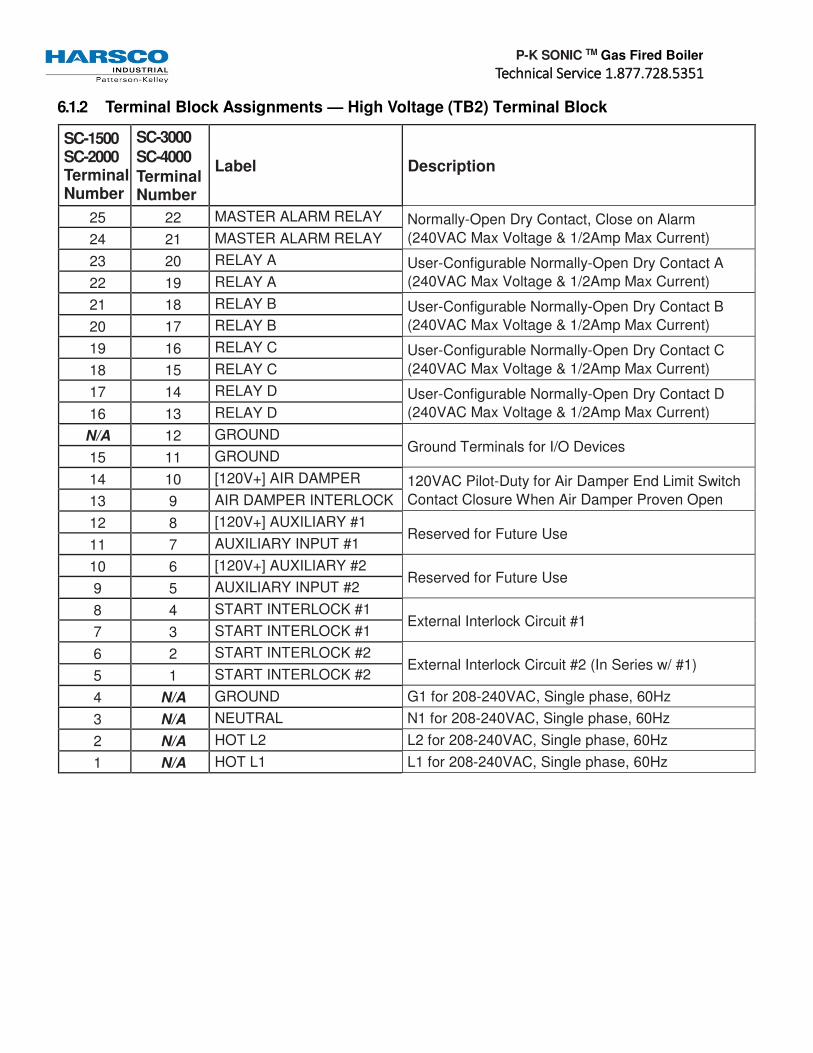
P-K SONIC TM Gas Fired Boiler
TTTTechnical Service 1.877.728.5351echnical Service 1.877.728.5351echnical Service 1.877.728.5351echnical Service 1.877.728.5351
6.1.2 Terminal Block Assignments — High Voltage (TB2) Terminal Block
SC-1500 SC-2000 Terminal Number
SC-3000
SC-4000
Terminal Number
Label Description
25 22 MASTER ALARM RELAY Normally-Open Dry Contact, Close on Alarm
(240VAC Max Voltage & 1/2Amp Max Current) 24 21 MASTER ALARM RELAY
23 20 RELAY A User-Configurable Normally-Open Dry Contact A
(240VAC Max Voltage & 1/2Amp Max Current) 22 19 RELAY A
21 18 RELAY B User-Configurable Normally-Open Dry Contact B
(240VAC Max Voltage & 1/2Amp Max Current) 20 17 RELAY B
19 16 RELAY C User-Configurable Normally-Open Dry Contact C
(240VAC Max Voltage & 1/2Amp Max Current) 18 15 RELAY C
17 14 RELAY D User-Configurable Normally-Open Dry Contact D
(240VAC Max Voltage & 1/2Amp Max Current) 16 13 RELAY D
N/A 12 GROUND Ground Terminals for I/O Devices
15 11 GROUND
14 10 [120V+] AIR DAMPER 120VAC Pilot-Duty for Air Damper End Limit Switch
Contact Closure When Air Damper Proven Open 13 9 AIR DAMPER INTERLOCK
12 8 [120V+] AUXILIARY #1 Reserved for Future Use
11 7 AUXILIARY INPUT #1
10 6 [120V+] AUXILIARY #2 Reserved for Future Use
9 5 AUXILIARY INPUT #2
8 4 START INTERLOCK #1 External Interlock Circuit #1
7 3 START INTERLOCK #1
6 2 START INTERLOCK #2 External Interlock Circuit #2 (In Series w/ #1)
5 1 START INTERLOCK #2
4 N/A GROUND G1 for 208-240VAC, Single phase, 60Hz
3 N/A NEUTRAL N1 for 208-240VAC, Single phase, 60Hz
2 N/A HOT L2 L2 for 208-240VAC, Single phase, 60Hz
1 N/A HOT L1 L1 for 208-240VAC, Single phase, 60Hz

P-K SONIC TM Gas Fired Boiler
TTTTechnical Service 1.877.728.5351echnical Service 1.877.728.5351echnical Service 1.877.728.5351echnical Service 1.877.728.5351
6.1.3 Terminal Block Assignments — Low Voltage (TB1) Terminal Block
Terminal Number Label Description
27 ECOM 3
Wireless Outdoor Air Receiver 26 ECOM 2
25 ECOM 1
24 MODBUS SHIELD
2-Wire MODBUS RS485 & Shield Terminal 23 MODBUS COM B
22 MODBUS COM A
21 MODBUS/CASCADE REF Reference Terminal (Application Dependent)
20 CASCADE B TO B
2-Wire Cascade & Shield Terminal 19 CASCADE A TO A
18 CASCADE SHIELD
17 GROUND Ground Terminal for I/O Devices
16 ANALOG OUTPUT [-] 4-20mA Analog Output Tracks Boiler Firing Rate
100% Firing Rate = 20mA, 1% Firing Rate = 4mA 15 4-20mA ANALOG OUTPUT [+]
14 NIGHT SETBACK Contact Closure Enables Night Setback Operation
Open Circuit Disables Night Setback Operation 13 NIGHT SETBACK
12 OUTDOOR TEMP SENSOR Outdoor Air Temperature Sensor for ODA Reset
Configurable for 10kΩ or 12kΩ Sensor 11 OUTDOOR TEMP SENSOR
10 DHW STAT / SENSOR DHW Enable Circuit Configurable for SPST Break-on-rise Aquastat, or 10kΩ or 12kΩ Tank Sensor 9 DHW STAT / SENSOR
8 HDR TEMP SENSOR Hydronic Supply Header Temperature Sensor
Configurable for 10kΩ or 12kΩ Sensor 7 HDR TEMP SENSOR
6 SPARE ANALOG INPUT Reserved for Future Use
5 SPARE ANALOG INPUT
4 ANALOG INPUT [-] 4-20mA Analog Input
Configurable for Setpoint or Firing Rate Control 3 4-20mA ANALOG INPUT [+]
2 ENABLE / DISABLE Contact Closure Enables Comfort Heat Operation
Open Circuit Disables Comfort Heat Operation 1 ENABLE / DISABLE
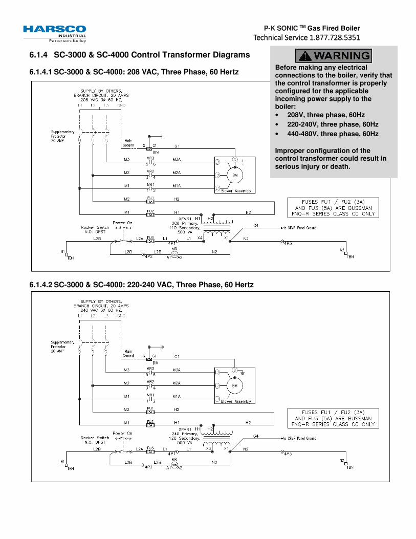
P-K SONIC TM Gas Fired Boiler
TTTTechnical Service 1.877.728.5351echnical Service 1.877.728.5351echnical Service 1.877.728.5351echnical Service 1.877.728.5351
6.1.4 SC-3000 & SC-4000 Control Transformer Diagrams
6.1.4.1 SC-3000 & SC-4000: 208 VAC, Three Phase, 60 Hertz
6.1.4.2 SC-3000 & SC-4000: 220-240 VAC, Three Phase, 60 Hertz
Before making any electrical connections to the boiler, verify that the control transformer is properly configured for the applicable incoming power supply to the boiler:
• 208V, three phase, 60Hz
• 220-240V, three phase, 60Hz
• 440-480V, three phase, 60Hz
Improper configuration of the control transformer could result in serious injury or death.
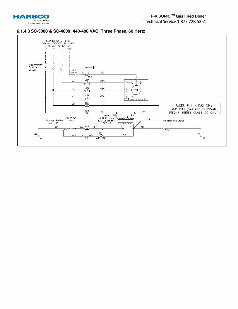
P-K SONIC TM Gas Fired Boiler
TTTTechnical Service 1.877.728.5351echnical Service 1.877.728.5351echnical Service 1.877.728.5351echnical Service 1.877.728.5351
6.1.4.3 SC-3000 & SC-4000: 440-480 VAC, Three Phase, 60 Hertz

P-K SONIC TM Gas Fired Boiler
TTTTechnical Service 1.877.728.5351echnical Service 1.877.728.5351echnical Service 1.877.728.5351echnical Service 1.877.728.5351
6.1.5 SC-1500 & SC-2000 Wiring Diagram

P-K SONIC TM Gas Fired Boiler
TTTTechnical Service 1.877.728.5351echnical Service 1.877.728.5351echnical Service 1.877.728.5351echnical Service 1.877.728.5351
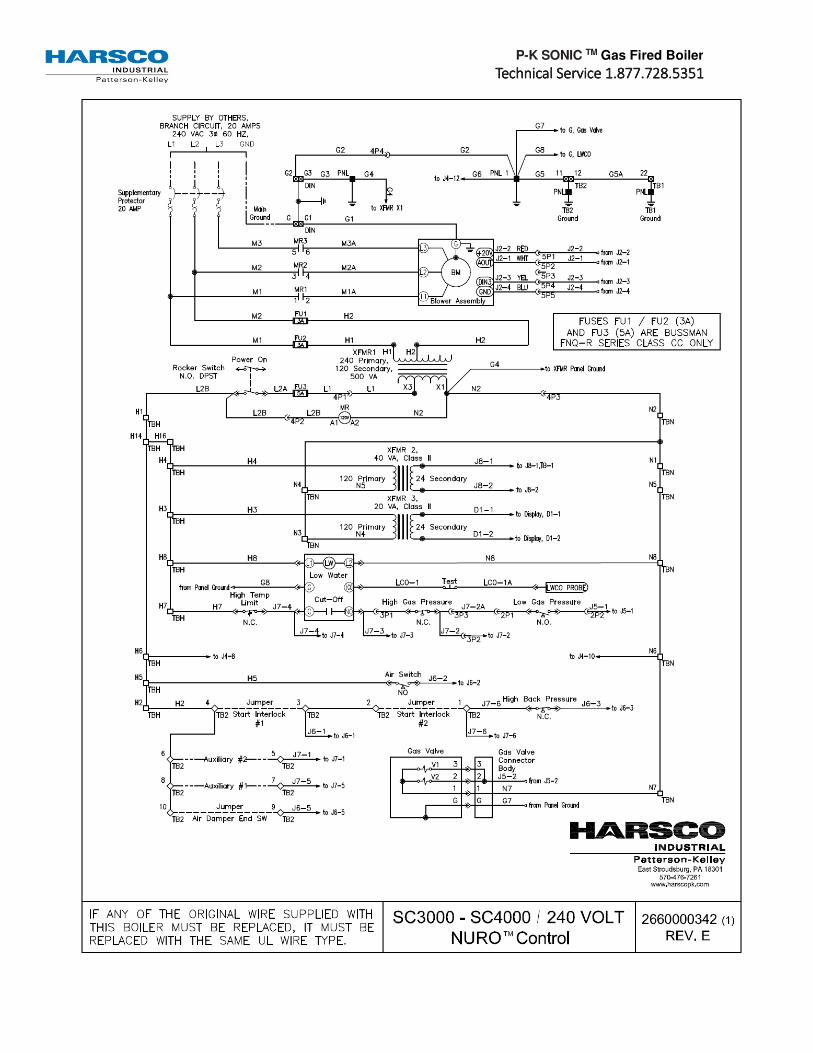
P-K SONIC TM Gas Fired Boiler
TTTTechnical Service 1.877.728.5351echnical Service 1.877.728.5351echnical Service 1.877.728.5351echnical Service 1.877.728.5351

P-K SONIC TM Gas Fired Boiler
TTTTechnical Service 1.877.728.5351echnical Service 1.877.728.5351echnical Service 1.877.728.5351echnical Service 1.877.728.5351

P-K SONIC TM Gas Fired Boiler
TTTTechnical Service 1.877.728.5351echnical Service 1.877.728.5351echnical Service 1.877.728.5351echnical Service 1.877.728.5351
6.1.6 SC-3000 & SC-4000 480V Wiring Diagram
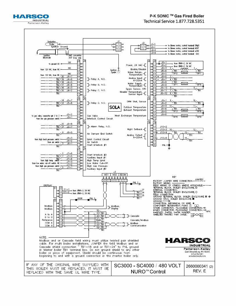
P-K SONIC TM Gas Fired Boiler
TTTTechnical Service 1.877.728.5351echnical Service 1.877.728.5351echnical Service 1.877.728.5351echnical Service 1.877.728.5351
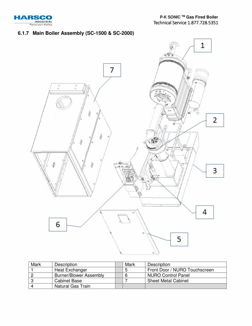
P-K SONIC TM Gas Fired Boiler
TTTTechnical Service 1.877.728.5351echnical Service 1.877.728.5351echnical Service 1.877.728.5351echnical Service 1.877.728.5351
6.1.7 Main Boiler Assembly (SC-1500 & SC-2000)
Mark Description Mark Description 1 Heat Exchanger 5 Front Door / NURO Touchscreen 2 Burner/Blower Assembly 6 NURO Control Panel 3 Cabinet Base 7 Sheet Metal Cabinet 4 Natural Gas Train

P-K SONIC TM Gas Fired Boiler
TTTTechnical Service 1.877.728.5351echnical Service 1.877.728.5351echnical Service 1.877.728.5351echnical Service 1.877.728.5351
6.1.8 NURO Control Panel (SC-1500 & SC-2000)
Mark Description Mark Description 1 Push to Test LWCO Button 7 NURO Touchscreen Assembly 2 Manual Reset Hi Temp Limit 8 Clear Plastic Protective Cover 3 Circuit Breaker 9 High Voltage (TB2) Terminal Block 4 On/Off Switch 10 Low Voltage (TB1) Terminal Block 5 SOLA Mainboard 11 Transformer XFMR2 (40VA) 6 Ignition Cable 12 Transformer XFMR1 (20VA)

P-K SONIC TM Gas Fired Boiler
TTTTechnical Service 1.877.728.5351echnical Service 1.877.728.5351echnical Service 1.877.728.5351echnical Service 1.877.728.5351
6.1.9 Heat Exchanger Assembly (SC-1500 & SC-2000)
Mark Description Mark Description 1 Outlet Coupling (3” Victaulic) 9 High Exhaust Pressure Switch Port 2 Relief Valve Port 10 Heat Exchanger 3 Supply Temperature Sensor 11 Heat Exch. Temperature Sensor 4 Inlet Coupling (3” Victaulic) 12 Burner Flange / Hole 5 Manual Drain Valve 13 Low Water Cutoff Probe 6 10” Flue Adapter 14 Manual Reset High Limit Probe 7 Condensate Pan 15 Automatic Air Vent 8 Condensate Trap

P-K SONIC TM Gas Fired Boiler
TTTTechnical Service 1.877.728.5351echnical Service 1.877.728.5351echnical Service 1.877.728.5351echnical Service 1.877.728.5351
6.1.10 Natural Gas Train, Burner & Blower Assembly (SC-1500 & SC-2000)
Mark Description Mark Description 1 Stainless Steel Mesh Burner 9 Blower Transition Piece 2 External (Upstream) Gas Cock 10 Combustion Blower / Fan 3 Gas Piping & Supports 11 Burner Transition Piece 4 Air Intake Transition Piece 12 Ignition Electrode & Gasket 5 Low Gas Pressure Switch 13 Flame/Ionization Rod & Gasket 6 High Gas Pressure Switch 14 Outer Burner Gasket 7 Main Gas Shutoff/Control Valve 15 Inner Burner Gasket 8 Internal (Downstream) Gas Cock

P-K SONIC TM Gas Fired Boiler
TTTTechnical Service 1.877.728.5351echnical Service 1.877.728.5351echnical Service 1.877.728.5351echnical Service 1.877.728.5351
6.2 Boiler Parts Identification (SC-3000 & SC-4000)
6.2.1 Main Boiler Assembly (SC-3000 & SC-4000)
Mark Description Mark Description 1 Heat Exchanger 5 Main Power Box 2 Burner/Blower Assembly 6 Front Door / NURO Touchscreen 3 Cabinet Base 7 NURO Control Panel 4 Natural Gas Train 8 Sheet Metal Cabinet

P-K SONIC TM Gas Fired Boiler
TTTTechnical Service 1.877.728.5351echnical Service 1.877.728.5351echnical Service 1.877.728.5351echnical Service 1.877.728.5351
6.2.2 NURO Control Panel (SC-3000 & SC-4000)
Mark Description Mark Description 1 Push to Test LWCO Button 7 NURO Touchscreen Assembly 2 Manual Reset Hi Temp Limit 8 Clear Plastic Protective Cover 3 Fuse Holder & Fuse 9 High Voltage (TB2) Terminal Block 4 On/Off Switch 10 Low Voltage (TB1) Terminal Block 5 SOLA Mainboard 11 Transformer XFMR2 (40VA) 6 Ignition Cable 12 Transformer XFMR1 (20VA)

P-K SONIC TM Gas Fired Boiler
TTTTechnical Service 1.877.728.5351echnical Service 1.877.728.5351echnical Service 1.877.728.5351echnical Service 1.877.728.5351
6.2.3 Main Power Box (SC-3000 & SC-4000)
Mark Description Mark Description 1 20A Three Phase Breaker
(Incoming Three Phase Power) 4 Fuse Holder
2 Grounding Terminal 5 Power Lead to Blower Motor 3 Control Transformer 6 Blower Motor Relay
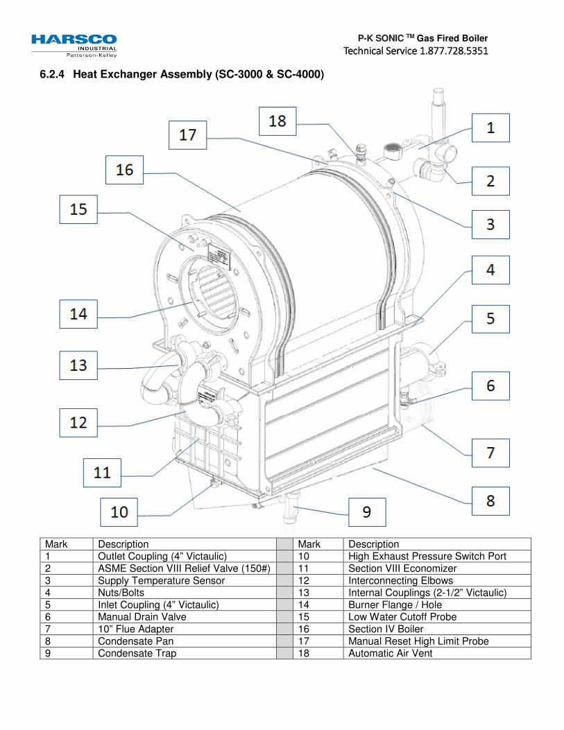
P-K SONIC TM Gas Fired Boiler
TTTTechnical Service 1.877.728.5351echnical Service 1.877.728.5351echnical Service 1.877.728.5351echnical Service 1.877.728.5351
6.2.4 Heat Exchanger Assembly (SC-3000 & SC-4000)
Mark Description Mark Description 1 Outlet Coupling (4” Victaulic) 10 High Exhaust Pressure Switch Port 2 ASME Section VIII Relief Valve (150#) 11 Section VIII Economizer 3 Supply Temperature Sensor 12 Interconnecting Elbows 4 Nuts/Bolts 13 Internal Couplings (2-1/2” Victaulic) 5 Inlet Coupling (4” Victaulic) 14 Burner Flange / Hole 6 Manual Drain Valve 15 Low Water Cutoff Probe 7 10” Flue Adapter 16 Section IV Boiler 8 Condensate Pan 17 Manual Reset High Limit Probe 9 Condensate Trap 18 Automatic Air Vent

P-K SONIC TM Gas Fired Boiler
TTTTechnical Service 1.877.728.5351echnical Service 1.877.728.5351echnical Service 1.877.728.5351echnical Service 1.877.728.5351
6.2.5 Natural Gas Train, Burner & Blower Assembly (SC-3000 & SC-4000)
Mark Description Mark Description 1 Stainless Steel Mesh Burner 8 High Gas Pressure Switch 2 External (Upstream) Gas Cock 9 Blower Transition Piece 3 Gas Piping & Supports 10 Burner Transition Piece 4 Blower Motor Splash Guard 11 Flame/Ionization Rod & Gasket 5 Combustion Blower / Fan 12 Ignition Electrode & Gasket 6 Low Gas Pressure Switch 13 Outer Burner Gasket 7 Main Gas Shutoff/Control Valve 14 Inner Burner Gasket

P-K SONIC TM Gas Fired Boiler
TTTTechnical Service 1.877.728.5351echnical Service 1.877.728.5351echnical Service 1.877.728.5351echnical Service 1.877.728.5351
6.2.6 Propane Gas Train (SC-3000 & SC-4000)
Mark Description Mark Description 1 External (Upstream) Gas Cock 5 Internal (Downstream) Gas Cock 2 Gas Piping & Supports 6 High Gas Pressure Switch 3 Flexible Gas Hose 7 Main Gas Shutoff/Control Valve 4 Low Gas Pressure Switch

P-K SONIC TM Gas Fired Boiler
TTTTechnical Service 1.877.728.5351echnical Service 1.877.728.5351echnical Service 1.877.728.5351echnical Service 1.877.728.5351
7 Limited Warranty
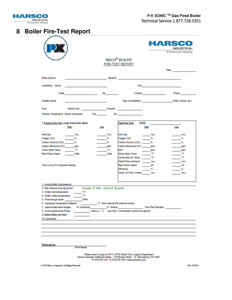
P-K SONIC TM Gas Fired Boiler
TTTTechnical Service 1.877.728.5351echnical Service 1.877.728.5351echnical Service 1.877.728.5351echnical Service 1.877.728.5351
8 Boiler Fire-Test Report

P-K SONIC TM Gas Fired Boiler
TTTTechnical Service 1.877.728.5351echnical Service 1.877.728.5351echnical Service 1.877.728.5351echnical Service 1.877.728.5351
Appendix A – Maintenance Log
Date Hi Fire / Low Fire
O2 CO CO2 Stack Temp
pH Action By

P-K SONIC TM Gas Fired Boiler
TTTTechnical Service 1.877.728.5351echnical Service 1.877.728.5351echnical Service 1.877.728.5351echnical Service 1.877.728.5351
Appendix B – Boiler Altitude Derate Schedule
For installations over 2000 ft. elevations, a derate schedule is applied. The boiler input rating must be reduced by 4% per 1000 ft. which is illustrated in the graph below.
Derate procedure is as follows:
With the boiler at high fire, adjust the gas valves to get 5% O2 in the flue gas. Refer to Section 3.12.2 Combustion Setup and Adjustment.
If this cannot be achieved, perform the following steps:
• If the O2% is too high, then the inlet gas pressure should be adjusted to the minimum pressure allowed, typically 5” W.C. The gas valve should be adjusted to obtain approximately 5% O2. If the O2% is still too high, the fan speed may be lowered. This procedure should only be performed by factory trained personnel.
• If the O2% is too low, then the gas valve settings should be reduced. This procedure is also described in Bulletin 06-08.

P-K SONIC TM Gas Fired Boiler
TTTTechnical Service 1.877.728.5351echnical Service 1.877.728.5351echnical Service 1.877.728.5351echnical Service 1.877.728.5351
Appendix C – Water Quality Standards Quality Standards for Hydronic Boilers in Multi-Metal Systems
HARSCO Industrial Patterson-Kelley boilers are designed to be incorporated into any multi-metal hydronic heating system. All multi-metal hydronic systems require that attention be paid to water treatment. The chemical additives for any multi-metal system must be specifically formulated for use with all the various metals used in that system. Any closed, hydronic heating systems should include a meter, to monitor water addition to the recirculating loop, and a filter, pursuant to ASHRAE Standard 189.1 and the AWT Handbook. Water added to a closed hydronic system should not exceed more than 10% of the system volume per year and meter readings should be recorded, at least monthly, to ensure system losses are minimized and corrective actions shall be taken when needed. Treatment programs for multi-metal systems should meet or exceed the following generally accepted best practices water quality guidelines: Prior to initiating any treatment program, a water sample of the proposed fill water should be sampled for analysis. Once filled and bled of air, a pH neutral, industrial cleaner for use in multi-metal systems should be used to clean the entire hydronic system. Samples of the system water with cleaner should be taken and analyzed to ensure proper cleaner strength. Once cleaned, the system should be flushed with fresh (fill) water until the system water is within 100 micro Siemens in conductivity of the fresh water. When flushing is complete, a treatment program that is designed for use in that multi-metal system, after consideration of the metals it contains, must be used. Treatment programs should also comply with the standard water quality guidelines listed below.

P-K SONIC TM Gas Fired Boiler
TTTTechnical Service 1.877.728.5351echnical Service 1.877.728.5351echnical Service 1.877.728.5351echnical Service 1.877.728.5351
Appendix D – Installation and Quick Reference
Fuel/Gas Supply
• Refer to Section 3.6 Piping for information on proper sizing of the gas supply piping. Undersized gas piping with too much pressure drop will negatively impact the boiler’s performance.
• Install a lock-up type gas regulator to supply an appropriate gas pressure as described below:
Natural Gas Propane Gas
Minimum Inlet Pressure = 4.0” W.C.
Maximum Inlet Pressure = 14.0” W.C.
Minimum Inlet Pressure = 7.0” W.C.
Maximum Inlet Pressure = 14.0” W.C.
NOTE
Harsco Industrial, Patterson-Kelley recommends installing an individual lock-up type gas regulator in the gas supply piping to each boiler. For installations where one master lock-up type gas pressure regulator will service multiple boilers, Patterson-Kelley recommends contacting the local regulator representative for application assistance specifying the appropriate lock-up type regulator and gas pipe sizing.
Electrical/Power Supply
• Carefully inspect the boiler’s nameplate labels which describe the power supply requirements.
• Provide an appropriate power feed to the boiler with overcurrent protection:
Boiler Model Power Supply Requirements
SC-1500 / SC-2000 (240V) 208-240VAC, single phase, 60Hz sized for 15 Amps.
SC-3000 / SC-4000 (240V) 208-240VAC, three phase, 60Hz sized for 20 Amps.
SC-3000 / SC-4000 (480V) 460-480VAC, three phase, 60Hz sized for 20 Amps.
NOTE
The SC-3000 & SC-4000 MUST be ordered to the correct voltage! IT IS NOT POSSIBLE to convert an SC-3000 or SC-4000 between the 240V and 480V configurations in the field.
• Prior to startup, carefully check all electrical connections for tightness as connections can come lose during shipping.
Exhaust Venting
• The P-K SONIC TM boilers are dual-certified as Category II & Category IV appliances, capable of operating with slightly negative to slightly positive exhaust pressure. It is critical to ensure the flue venting material is suitable for use with the boiler.
• For Category II installations, ensure the flue venting system is designed to maintain a slightly negative exhaust pressure which does not exceed -0.04” W.C.
• For Category IV installations, ensure the flue venting system is designed to maintain a slightly positive exhaust pressure which does not exceed +0.22” W.C.

P-K SONIC TM Gas Fired Boiler
TTTTechnical Service 1.877.728.5351echnical Service 1.877.728.5351echnical Service 1.877.728.5351echnical Service 1.877.728.5351
Hydronics/Water Flow (SC-1500 / SC-2000)
The chart below represents the pressure drop (Ft of Head) versus the water flow rate (GPM) for the SONIC TM SC-1500 and SC-2000 boilers. This information is useful to help size an appropriate circulation pump. Keep in mind this pressure drop represents the boiler only, additional consideration is needed for any connecting piping, valves, strainers, couplings, flanges, etc ∆.
® SC-1500 / SC-2000
o∆T
The table below summarizes the minimum and maximum flow restrictions for the SC-1500 and SC-2000 boilers:
Flow Condition Boiler Operation Flow Rate Approximate ∆T
Maximum Flow High Fire 192 GPM 20 °F Minimum Flow Ignition 48 GPM 20 °F Minimum Flow Low Fire 38 GPM 20 °F

P-K SONIC TM Gas Fired Boiler
TTTTechnical Service 1.877.728.5351echnical Service 1.877.728.5351echnical Service 1.877.728.5351echnical Service 1.877.728.5351
Hydronics/Water Flow (SC-3000 / SC-4000)
The chart below represents the pressure drop (Ft of Head) versus the water flow rate (GPM) for the SONIC TM SC-3000 and SC-4000 boilers. This information is useful to help size an appropriate circulation pump. Keep in mind this pressure drop represents the boiler only, additional consideration is needed for any connecting piping, valves, strainers, couplings, flanges, etc ∆.
The table below summarizes the minimum and maximum flow restrictions for the SC-3000 boiler:
Flow Condition Boiler Operation Flow Rate Approximate ∆T
Maximum Flow High Fire 285 GPM 20 °F Minimum Flow Ignition 72 GPM 20 °F Minimum Flow Low Fire 57 GPM 20 °F
The table below summarizes the minimum and maximum flow restrictions for the SC-4000 boiler:
Flow Condition Boiler Operation Flow Rate Approximate ∆T
Maximum Flow High Fire 384 GPM 20 °F Minimum Flow Ignition 98 GPM 20 °F Minimum Flow Low Fire 76 GPM 20 °F