inside cameron innovations - cedip.edu.mxƒ³n de pemex... · and annulus valves are cameron fls...
TRANSCRIPT

Inside Cameron Innovations:
Complete Subsea Systems for West Africa
Deepwater Manifold and Connection Systems
Total Cameron Systems for Dry Completions
Award-Winning Environmental Safeguard System
High Availability CAMTROL System
New Cameron Willis Choke Designs
New Aftermarket Facility in Angola
Inside Cameron Innovations:
Complete Subsea Systems for West Africa
Deepwater Manifold and Connection Systems
Total Cameron Systems for Dry Completions
Award-Winning Environmental Safeguard System
High Availability CAMTROL System
New Cameron Willis Choke Designs
New Aftermarket Facility in Angola
Cameron Environmental SafeguardSystem allows quick, safe disconnectwhen drilling with surface BOPs.
Cameron Environmental SafeguardSystem allows quick, safe disconnectwhen drilling with surface BOPs.

centers requiring higher injection rateshave two manifolds linked together in a“daisy chain” fashion.
Connected to the manifolds are 23 wells completed with CameronSpoolTree Systems. The SpoolTreesystems are 5-1/8" x 2-1/16" 5000 psiand are designed for a 25-year servicelife with a temperature range of 0˚F to250˚F (-18˚C to 120˚C). Productionand annulus valves are Cameron FLSGate Valves with Compact Modular(CM™) Actuators. The trees also incor-porate Cameron collet connectors andCameron Willis CC40SR SubseaRetrievable Chokes. The CameronVertical Connection (CVC™) system is used for all hard pipe connections.
The control system for the project isthe Cameron CAMTROL AdvancedMultiplexed Electro-HydraulicControl System that features standard-ized, modular components, open
electronics architecture and highlyflexible hydraulics.
Offshore Systems
For the rapidly growing WestAfrican market, Cameron is providing system solutions for
several large developments. Cameronis providing deepwater subsea solutions
to operations in EquitorialGuinea, Nigeria and Angola.
As an example, one ofthese developments is locat-
ed in over 4000 feet (1200meters) of water and features
four distinct drill centers. Cameron equipment for this project
includes five water alternating gas man-ifolds. Each manifold has two headers,one for the gas injection flowline andone for the water injection flowline. 9" 5000 psi WP ROV-actuatedCameron gate valves isolate each main header. Dual valve blocks withhydraulically actuated Cameron valves allow for flow direction changefrom the headers to each well. Eachmanifold is installed via lift wirefrom the installation vessel. Drill
Cameron SpoolTree™ System
Water Alternating Gas Manifold SystemManifold with Two 10" Nominal HeadersSuction Foundation Pile and Pile Top6" CVC Hub Pressure Cap (6 per manifold)10" CVC Hub Pressure Cap (4 per manifold)Manifold Test SkidWater Alternating Gas SpoolTree Christmas Tree SystemsIntegral Spool Bodies and Protective StructuresFLS Gate ValvesCM ActuatorsCC40 Subsea Retrievable Chokes Aqua-Torq Choke ActuatorsDWH Tree Connectors Isolation SleeveDual Crown Plug Tubing Hanger Assembly Debris CapElectro-Hydraulic Umbilical Junction HubsContingency High Pressure CapAll Related Installation and Testing ToolsCAMTROL Production Control SystemSurface Components
Master Control Station (MCS)Hydraulic Power Unit (HPU)Electrical Power Unit (EPU)Topside Umbilical Termination Units (TUTU)
Subsea ComponentsSuction Foundation Pile and Pile TopFoundation Base to Support UTA and SDUUmbilical Termination Assembly (UTA)Subsea Distribution Unit (SDU)Subsea Accumulator Modules (SAM)Electric, Hydraulic and Chemical Flying Lead
JumpersSubsea Control Modules (SCM)Subsea Control Module Mounting Bases
(SCMMB)Tree and Manifold Mounted InstrumentationParking Plates and Deployment BasketsProtective CoversTest Equipment
UmbilicalsElectro (Power and Signal) – Hydraulic – Chemical
Umbilicals to communicate from the FPSO to each of the drill centers.
Approximate length 3 miles (5000 m).Cameron Vertical Connection System (CVC)10" Nominal CVC Flowline Jumpers 6" Nominal CVC Flowline Jumpers Fabrication and Shipping EquipmentCVC Running Tools and RiggingInstallation/Workover Control SystemHydraulic Power Unit with Control PanelE-H Workover Umbilical and ReelerExternal Umbilical Deck Jumper HydraulicRemote ESD StationSurface Control UnitEmergency Quick Disconnect UnitUmbilical ClampsHydraulic and Electrical Flying LeadsPLETs (Pipeline End Terminal)CVC Hub and Receiver StructureConnections Hub Flooding Pressure CapCVC Connectors (for flowline commissioning)
S Y S T E M S C O P E O F S U P P LY

Drill Center One: One SpoolTree System, One CAMTROL Subsea Distribution Unit (SDU) and a Pipeline End Terminal (PLET)
Drill Center Two: One Cluster Manifold, Five SpoolTree Systems, a PLET and SDU
Drill Center Three: Two Cluster Manifolds, Eight SpoolTree Systems, Two PLETS and Two SDUs
Drill Center Four: Two Cluster Manifolds, Eight SpoolTree Systems, Three PLETS and Two SDUs
Offshore Systems

Cameron has applied morethan 40 years of subsea expe-rience to the design and
development of manifolds for today’ssubsea environments. Cameron hasinstalled a variety of manifold types invirtually any water depth and inoperating pressures up to andincluding 15,000 psi.
In most cases, the field layout determines the type ofmanifold system requiredand these elements arenormally rated for operat-ing pressures matching theChristmas trees. Cameronmanifolds can be configuredwith a wide array of choicesincluding:• Service. Manifolds are
available for production,water injection, gas injectionand water alternating gasapplications.
• Deployment Methods. Manifoldscan be deployed using three differ-ent types of vessels: drilling rig —through the moon pool or keel-hauled on drill string; heavy lift vessel — through moon pool or over side; work class vessel — overthe side with a crane or winch.
• Headers. Pipework headers canbe single or dual and eachheader connects to an individual flowline. Test headers can be incorporated to test an individual tree orgroups of trees.
Offshore Systems
• Gate Valves and Actuators. Cameronmanifolds incorporate a series of modular valve blocks with two valves
mounted in series. Manifoldcapacity can be increased byadding modular valve blockassemblies. Valves within the blocks can
be manually or hydraulical-ly actuated Cameron FLS™
or FLS-R™ Gate Valves for large-bore applications.
Valves can be mountedhorizontally or vertically.Cameron CompactModular (CM) Actuatorsare used for actuated valves. • Pigging Loops. Piggingloops may be retrievable,non-retrievable or internaland incorporate Cameron
gate valves or ball valves.• Foundation. Types of
foundations include mud mats, piles or intermediate structures for
larger manifolds.• Flowline Tie-In Connections.
Cameron manifolds incorporatea number of field-proven flow-line tie-in methods including
the Cameron VerticalConnection (CVC) andCameron HorizontalConnection (CHC™) collet-type connection
systems; Stab and Hinge-Over Connections; and the McPAC™ clamp-type connection system.
Typical Manifold Piping
CVC Connection
Dual ValveBlocks
Typical Cluster-Type Manifold
Retrievable Pigging Loop

With over 250 subsea connections already inplace, the Cameron
Vertical Connection (CVC™) Systemhas proven to be a highly successfuland popular system for connectingflowlines and export lines.
Basic components of the systeminclude a hub support mounted onthe subsea structure and a receivermounted on the flowline to be con-nected. The hydraulic CVC runningtool is an independent tool which isoperated by ROV. Other major fea-tures of the CVC system include:• Strong, Mechanical Connection.
The CVC running tool incorporatesa hydraulically operated actuatorring which locks pivoting collet seg-ments under the tapered profile ofthe hub to form a strong connectioncapable of handling high bendingloads.
• Misalignments Minimized. Theconnection system can accommo-date 17 degrees of misalignment,permitting connections to be madeat high angles to minimize or elimi-nate misalignments.
• Simple Make-up. Collet connectorsare lowered directly onto the hubs.No draw-together motion is neededto make-up the connection.
• No Hydraulics Left Subsea.Because the CVC running tool iscompletely independent and isretrieved to the surface after the connection is made, no hydrauliccomponents are left subsea.
• Reduced Tooling. CVC runningtools are available in 4"-12" and 12"-20" size ranges, so one tool canbe used for several connection applications.
The M-shaped flowline withCVC running tools on eachend is lowered on a spreaderbeam.
The ROV hydraulicallyactuates the CVC runningtools to make up and verifythe connections.
The ROV releases the CVCrunning tools and the toolsand spreader bar areretrieved to the surface.
The flowline is complete,connecting the subsea treeto the manifold.
Offshore Systems

Cameron provides completesystem solutions for dry completions such as Tension
Leg Platform (TLP) and Deep DraftCaisson Vessel (DDCV) applications.Cameron’s comprehensive productline means that Cameron is uniquelyqualified to provide drilling and production systems, drilling and production controls systems as well as complete aftermarket services.
In addition, Cameron provides project management expertise; engi-neering, design and manufacturingexperience; complete R&D capabili-ties including analysis and strength
fatigue testing; site integration and factory acceptance testing; and installation supervision.
Typical Cameron components for a TLP system include:• Drilling Systems
Ram-Type BOPsAnnular BOPsDrilling ConnectorsDrilling ControlsSubsea WellheadsAdjustable Riser Hanger SystemsRiser Joints/CouplingsInternal Riser Tie-BacksRiser Tie-Back ConnectorsTensioner SystemsStress Joints
Dry Completion Systems
The Cameron External Tie-Back Connector is used in dry completion productionsystems to connect the subsea wellhead to the riser system.
The connector is an annular piston design which limits the maximum outsidediameter to only 32.50" (82.5 cm). Hydraulic pressure acting on the piston acti-vates collet segments similar to those in a traditional collet connector. In thelocked position, the segments close around the 18-3/4" wellhead mandrel.Additional features of the connector include:
• ROV Operation. Hydraulic functions are operated via an ROV panel mountedabove the connector to the stress joint.
• Metal-to-Metal Sealing. A metal-to-metal AX/VX gasket seals the connector tothe wellhead.
• High Load Bearing Capacity. The connector has been tested to withstand bending loads of 2300 feet kip at 5500 psig bore pressure and 2800 feet kip at 0 psig bore pressure while maintaining the metal-to-metal seal interface.
• Positive Unlock. The unlock piston can unlock the connector with up to a 0.30coefficient of friction. The connector also has a mechanical override which serves as an emergency disconnect.
• Positive Disengagement. A collet disengagement ring grips the bottom of thecollets when the connector is unlocked, pulling them back into the shell andretaining them during disengagement.
• Misalignment Protection. The retracted collets form a cone at the connector bottom that permits a five degree misalignment angle relative to the wellheadto prevent damage of the gasket seal area during installation.
• Production SystemsSurface Christmas TreesSurface WellheadsWellhead ConnectorsProduction RisersInternal Production Riser Tie-BacksProduction Riser Tie-Back
ConnectorsRiser Tensioner SystemsStress Joints
• Export SystemsExport Risers and Riser BasesManifolds/Tie-In Systems
• Tie-Back SystemsCameron also offers a similar suite
of equipment for DDCV and otherdeepwater applications.
E X T E R N A L T I E - B A C K C O N N E C T O R

Dry Completion Systems
Subsea Field Layout with Tie-Backs TLP Dry Completion System
Production Wellhead and Tree with Work Decks

Traditionally when surface BOPsare used in place of subseaBOPS, high pressure riser is
run from the surface BOPs to the seafloor where it is cemented in place.This means that the rig itself is essen-tially cemented in place, allowing nopractical means of disconnecting in theevent of bad weather or some other sortof emergency situation. Also, if any-thing should happen to damage the
high-pressure riser while drilling, thereis no way to contain the well fluids ordrilling fluids in the riser.
In order to prevent the potentiallycostly and dangerous situations thattraditional methods present, Cameronhas developed the EnvironmentalSafeguard (ESG™) System to provideprotection from riser failure and allowthe rig to be safely disconnected fromthe sea floor.
Drilling Systems
The subsea portion of the ESGsystem consists of upper and lowerconnectors, a ram-type BOP withshearing blind rams, and a control system (acoustic, electric, ROV-actuat-ed, or hydraulic). The subsea unit is tied back to the surface BOP stackvia a high pressure riser system,Cameron-exclusive triple barrel telescoping joint and a motioncompensation system.
Left to Right: Traditional Drilling with Surface BOPs; Drilling with Subsea BOPs; Drilling with Surface BOPs and Cameron ESG System
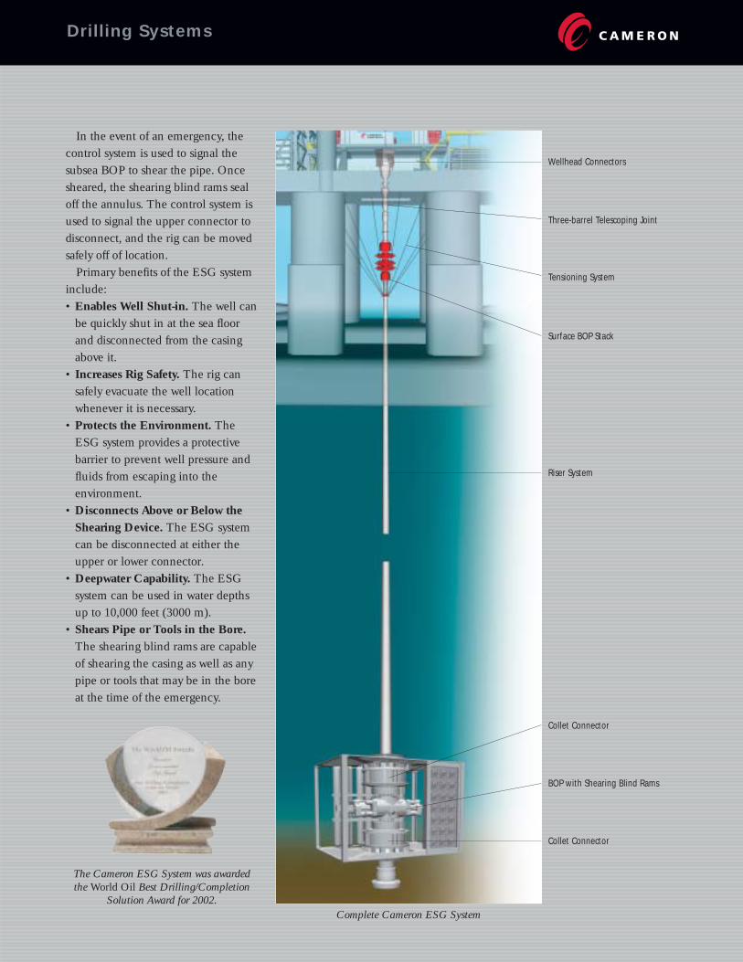
In the event of an emergency, thecontrol system is used to signal thesubsea BOP to shear the pipe. Oncesheared, the shearing blind rams sealoff the annulus. The control system isused to signal the upper connector todisconnect, and the rig can be movedsafely off of location.
Primary benefits of the ESG systeminclude:• Enables Well Shut-in. The well can
be quickly shut in at the sea floorand disconnected from the casingabove it.
• Increases Rig Safety. The rig cansafely evacuate the well locationwhenever it is necessary.
• Protects the Environment. TheESG system provides a protective barrier to prevent well pressure andfluids from escaping into the environment.
• Disconnects Above or Below theShearing Device. The ESG systemcan be disconnected at either theupper or lower connector.
• Deepwater Capability. The ESGsystem can be used in water depthsup to 10,000 feet (3000 m).
• Shears Pipe or Tools in the Bore.The shearing blind rams are capableof shearing the casing as well as anypipe or tools that may be in the boreat the time of the emergency.
The Cameron ESG System was awardedthe World Oil Best Drilling/Completion
Solution Award for 2002.
Wellhead Connectors
Three-barrel Telescoping Joint
Tensioning System
Surface BOP Stack
Riser System
Collet Connector
BOP with Shearing Blind Rams
Collet Connector
Drilling Systems
Complete Cameron ESG System
The successful delivery of asuper deepwater productioncontrol system requires dedica-
tion to proving and providing a highavailability system. And, with morethan 45 CAMTROL Subsea ControlModules operating in fields world-wide, the CAMTROL system hasachieved an average productionuptime-availability of 99.994%, an outstanding record.
The CAMTROL system wasdesigned at the system level to addressthe lessons learned over the past 30years of subsea controls experienceand incorporates the following designphilosophies as core drivers:• Robustness of Design. Based on
thorough qualification of system,equipment and components.
• Extensive supply chain management. Including coordina-tion and involvement of suppliers incomponent and sub-system designand qualification.
• Design Expertise. Use of standardmodular designs to achieve highestuptime availability at an effectivecost. Simplification of design where possible for the purposes of reliability.
• Fault-Tolerance. Enables minimizednon-productive time (NPT) and thuscontinued production, should anequipment/component failure occur.
• Material Qualification. Extensiveuse of materials qualified for sea-water tolerance.
• Extensive System Level Analysis.HAZOP/HAZID, failure modeseffects and criticality analysis(FMECA/FMEA) reliability availability and maintainability(RAM), human factors, galvanic
compatibility, leak path audit, elec-trical power and communications,hydraulic system analysis, operabilityand system connectivity, factory integration testing, etc.
• Standardization. The design of the CAMTROL system embracesthe concept of standard componentdesigns as one of the most cost-
Offshore Systems
effective approaches to improvingsystem reliability. It enablesCAMTROL components and systems to be reconfigured (versusredesigned) from one developmentto the next with predictable success.
• Maintenance Philosophy. TheCAMTROL system encompasses awhole life of development customercare and system maintenance philos-ophy. Whole life considerations aretailored to match the expecteddevelopment, operations environ-ment and geographic region of eachproject. For example, planned main-tenance activities are scheduledwhen an intervention vessel is avail-able. Additional emphasis consider-ing routine preventive maintenancebased around project schedulingevents where system availability isdeemed critical to development performance.
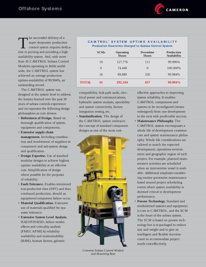
• Proven Technology. Standard andmodularized systems and equipmentis core to CAMTROL, and the SCMis the heart of the subsea system.The SCM is based on proven tech-nology but is re-packaged to reducesize and weight and to give an intelligent and flexible functioncount to accommodate projectneeds cost-effectively.
C A M T R O L™ S Y S T E M U P T I M E A V A I L A B I L I T YProduction Downtime Charged to Subsea Control System
SCMs Operating Downtime ProductionHours Hours Availability
19 127,776 111 99.996%
6 74,448 0 100.000%
16 89,880 326 99.984%
TOTAL 41 292,104 437 99.994%
Cameron Subsea Control Module and Mounting Base
Cameron Willis has expandedits highly successful range of surface and subsea control
chokes to include the CC80 ControlChoke, designed primarily for highflow capacity applications.
For surface applications, the CC80choke is an 8" nominal choke whichcan be used in production, waterinjection and gas lift applications. It has a maximum Cv of 1006. Thechoke uses a bolted bonnet design andincorporates plug and cage trim tech-nology to minimize erosion and maxi-mum controllability. The CC80 chokeis available in manual and actuatedconfigurations.
The Cameron Willis CC80 ControlChoke has seen successful service inAlaska where the application called for a water injection choke capable ofinjection rates in excess of 100,000BPD per well into seven wells.
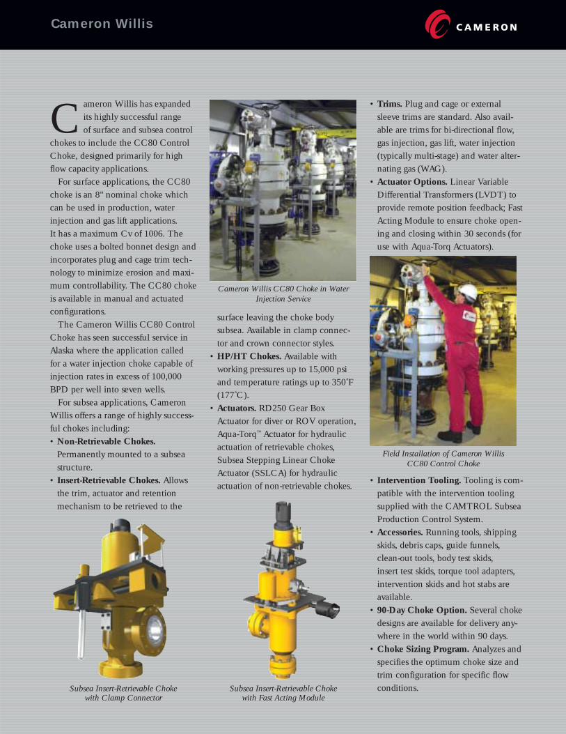
For subsea applications, CameronWillis offers a range of highly success-ful chokes including:• Non-Retrievable Chokes.
Permanently mounted to a subsea structure.
• Insert-Retrievable Chokes. Allowsthe trim, actuator and retentionmechanism to be retrieved to the
surface leaving the choke body subsea. Available in clamp connec-tor and crown connector styles.
• HP/HT Chokes. Available withworking pressures up to 15,000 psiand temperature ratings up to 350˚F(177˚C).
• Actuators. RD250 Gear BoxActuator for diver or ROV operation,Aqua-Torq™ Actuator for hydraulicactuation of retrievable chokes,Subsea Stepping Linear ChokeActuator (SSLCA) for hydraulicactuation of non-retrievable chokes.
• Trims. Plug and cage or externalsleeve trims are standard. Also avail-able are trims for bi-directional flow,gas injection, gas lift, water injection(typically multi-stage) and water alter-nating gas (WAG).
• Actuator Options. Linear VariableDifferential Transformers (LVDT) toprovide remote position feedback; FastActing Module to ensure choke open-ing and closing within 30 seconds (foruse with Aqua-Torq Actuators).
• Intervention Tooling. Tooling is com-patible with the intervention toolingsupplied with the CAMTROL SubseaProduction Control System.
• Accessories. Running tools, shippingskids, debris caps, guide funnels,clean-out tools, body test skids, insert test skids, torque tool adapters,intervention skids and hot stabs areavailable.
• 90-Day Choke Option. Several chokedesigns are available for delivery any-where in the world within 90 days.
• Choke Sizing Program. Analyzes andspecifies the optimum choke size andtrim configuration for specific flowconditions. Subsea Insert-Retrievable Choke
with Clamp ConnectorSubsea Insert-Retrievable Choke
with Fast Acting Module
Cameron Willis CC80 Choke in WaterInjection Service
Field Installation of Cameron Willis CC80 Control Choke
Cameron Willis
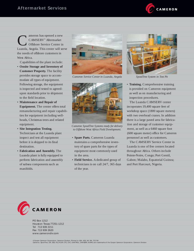
Cameron has opened a newCAMSERV™ AftermarketOffshore Service Center in
Luanda, Angola. This center will servethe needs of offshore customers inWest Africa.
Capabilities of the plant include:• Onsite Storage and Inventory of
Customer Property. The facility provides storage space to accom-modate all types of equipment.Following storage, the equipment is inspected and tested to agreed-upon standards prior to shipment to the field location.
• Maintenance and Repair of Equipment. The center offers totalremanufacturing and repair capabili-ties for equipment including well-heads, Christmas trees and relatedequipment.
• Site Integration Testing.Technicians at the Luanda plantinspect and test all equipmentbefore it is shipped to its final destination.
• Fabrication and Assembly. TheLuanda plant is fully equipped toperform fabrication and assembly of subsea components such as manifolds.
• Spare Parts. Cameron Luandamaintains a comprehensive inven-tory of spare parts for the types ofequipment most commonly used in the area.
• Field Service. A dedicated group oftechnicians is on call 24/7, 365 daysof the year.
Aftermarket Services
• Training. Comprehensive training is provided on Cameron equipmentas well as on manufacturing andinspection procedures. The Luanda CAMSERV center
incoporates 19,400 square feet ofworkshop space (1800 square meters)with two overhead cranes. In additionthere is a large paved area for fabrica-tion and storage of customer equip-ment, as well as a 6460 square foot(600 square meter) office for Cameronpersonnel as well as customers.
The CAMSERV Service Center inLuanda is one of five centers locatedthroughout Africa. Others includePointe-Noire, Congo; Port Gentil,Gabon; Malabo, Equatorial Guinea;and Port Harcourt, Nigeria.
Cameron Service Center in Luanda, Angola
Cameron SpoolTree Systems ready for delivery to Offshore West Africa Field Development.
SpoolTree System in Test Pit
PO Box 1212Houston Texas 77251-1212Tel 713 939 2211Fax 713 939 2620www.camerondiv.com
©Cooper Cameron Corporation, Cameron Division, Printed in USA, 4/03, WL 5M, TC1748Cameron, SpoolTree, CM, ESG, FLS, FLS-R, CTC, CVC, CAMTROL, CAMSERV, McPAC are trademarks of the Cooper Cameron Corporation, Cameron Division