inside usb transfers - proyectosfie.webcindario.com · ter has essentials that apply to all...
TRANSCRIPT

Inside USB Transfers
USB Complete 33
2
Inside USB TransfersThis and the next three chapters are a tutorial on USB transfers. This chap-ter has essentials that apply to all transfers. The following chapters cover thefour transfer types supported by USB, the enumeration process, and thestandard requests used in control transfers.
You don’t need to know every bit of this information to get a project up andrunning, but understanding something about how transfers work can helpin deciding which transfer types to use, writing device firmware, and debug-ging.
The information in these chapters is dense. If you don’t have a backgroundin USB, you won’t absorb it all in one reading. You should, however, get afeel for how USB works, and will know where to look later when you needto check the details.
The ultimate authority on the USB interface is the specification document,Universal Serial Bus Specification, available on the USB-IF’s Web site. Bydesign, the specification omits information and tips that are unique to anyoperating system or controller chip. This type of information is essential

Chapter 2
34 USB Complete
when you’re designing a product for the real world, so I include this infor-mation where relevant.
Transfer BasicsYou can divide USB communications into two categories: communicationsused in enumerating the device and communications used by the applica-tions that carry out the device’s purpose. During enumeration, the hostlearns about the device and prepares it for exchanging data. Applicationcommunications occur when the host exchanges data that performs thefunctions the device is designed for. For example, for a keyboard, the appli-cation communications are the sending of keypress data to the host to tell anapplication to display a character or perform another action.
Enumeration CommunicationsDuring enumeration, the device’s firmware responds to a series of standardrequests from the host. The device must identify each request, returnrequested information, and take other actions specified by the requests.
On PCs, Windows performs the enumeration, so there’s no user program-ming involved. However, to complete the enumeration, on first attachment,Windows must locate an INF file that identifies the file name and locationof the device’s driver. If the required files are available and the firmwarefunctions correctly, the enumeration process is generally invisible to users.Chapter 9 has more details about device drivers and INF files.
Application CommunicationsAfter the host has exchanged enumeration information with the device anda device driver has been assigned and loaded, the application communica-tions can begin. At the host, applications can use standard Windows APIfunctions or other software components to read and write to the device. Atthe device, transferring data typically requires either placing data to send inthe USB controller’s transmit buffer or retrieving received data from thereceive buffer, and on completing a transfer, ensuring that the device is ready

Inside USB Transfers
USB Complete 35
for the next transfer. Most devices also require additional firmware supportfor handling errors and other events. Each data transfer uses one of the fourtransfer types: control, interrupt, bulk, or isochronous. Each has a formatand protocol to suit different needs.
Managing Data on the BusUSB’s two signal lines carry data to and from all of the devices on the bus.The wires form a single transmission path that all of the devices must share.(As explained later in this chapter, an exception is a cable segment between a1.x device and a 2.0 hub on a high-speed bus, but even here, all data shares apath between the hub and host.) Unlike RS-232, which has a TX line tocarry data in one direction and an RX line for the other direction, USB’spair of wires carries a single differential signal, with the directions takingturns.
The host is in charge of seeing that all transfers occur as quickly as possible.The host manages the traffic by dividing time into chunks called frames (atlow and full speeds) or microframes (at high speed). The host allocates aportion of each frame or microframe to each transfer (Figure 2-1). A framehas a period of one millisecond. For high speed traffic, the host divides eachframe into eight 125-microsecond microframes. Each frame or microframebegins with a Start-of-Frame timing reference.
Figure 2-1: At low and full speeds, the host schedules transactions within 1-millisecond frames.The host may schedule transactions anywhere it wants within a frame. The process is similar at high speed, but using 125-microsecond microframes.
Chapter 2
36 USB Complete
Each transfer consists of one or more transactions. Control transfers alwayshave multiple transactions because they have multiple stages, each consistingof one or more transactions. Other transfer types use multiple transactionswhen they have more data than will fit in a single transaction. Dependingon how the host schedules the transactions and the speed of a device’sresponse, a transfer’s transactions may all be in a single frame or microframe,or they may be spread over multiple (micro)frames.
Because all of the traffic shares a data path, each transaction must include adevice address that identifies the transaction’s destination. Every device has aunique address assigned by the host, and all data travels to or from the host.Each transaction begins when the host sends a block of information thatincludes the address of the receiving device and a specific location, called anendpoint, within the device. Everything a device sends is in response toreceiving a packet sent by the host.
Host Speed and Bus SpeedUSB 2.0 hosts in general-purpose PCs support low, full, and high speeds. A1.x host supports low and full speeds only. (Special-purpose hosts, typicallyfound in small embedded systems, don’t always support all speeds.)
A 1.x hub doesn’t convert between speeds; it just passes received traffic up ordown the bus, changing only the edge rate and signal polarity of traffic toand from attached low-speed devices. In contrast, a 2.0 hub acts as a remoteprocessor with store-and-forward capabilities. The hub converts betweenhigh speed and low or full speed as needed and performs other functionsthat help make efficient use of the bus time. The added intelligence of 2.0hubs is a major reason why the high-speed bus remains compatible with 1.xhardware.
The traffic on a bus segment is high speed only if the device is high speedand the host controller and all hubs between the host and device are2.0-compliant. Figure 2-2 illustrates. A high-speed bus may also have 1.xhubs, and if so, any bus segments downstream from this hub (away from thehost) are low or full speed. Traffic to and from low- and full-speed devicestravels at high speed between the host and any 2.0 hubs that connect to the

Inside USB Transfers
USB Complete 37
host with no 1.x hubs between. Traffic between a 2.0 hub and a 1.x hub oranother low- or full-speed device travels at low or full speed. A bus with onlya 1.x host controller supports only low and full speeds, even if the bus has2.0 hubs and high-speed-capable devices.
Elements of a TransferEvery USB transfer consists of one or more transactions, and each transac-tion in turn contains packets that contain information. To understand trans-actions, packets, and their contents, you also need to know about endpointsand pipes. So that’s where we’ll begin.
Figure 2-2: A USB 2.0 hub uses high speed whenever possible, switching to low and full speeds when necessary.
Chapter 2
38 USB Complete
Device Endpoints: the Source and Sink of DataAll bus traffic travels to or from a device endpoint. The endpoint is a bufferthat stores multiple bytes. Typically the endpoint is a block of data memoryor a register in the controller chip. The data stored at an endpoint may bereceived data or data waiting to transmit. The host also has buffers that holdreceived data and data waiting to transmit, but the host doesn’t have end-points. Instead, the host serves as the start and finish for communicationswith device endpoints.
The USB specification defines a device endpoint as “a uniquely addressableportion of a USB device that is the source or sink of information in a com-munication flow between the host and device.” This definition suggests thatan endpoint carries data in one direction only. However, as I’ll explain, acontrol endpoint is a special case that is bidirectional.
An endpoint’s address consists of an endpoint number and direction. Thenumber is a value from 0 to 15. The direction is defined from the host’s per-spective: an IN endpoint providess data to send to the host and an OUTendpoint stores data received from the host. An endpoint configured forcontrol transfers must transfer data in both directions, so a control endpointactually consists of a pair of IN and OUT endpoint addresses that share anendpoint number.
Every device must have Endpoint 0 configured as a control endpoint.There’s rarely a need for additional control endpoints. Some controller chipssupport them, however.
Other types of transfers send data in one direction only, though status andcontrol information may flow in the opposite direction. A single endpointnumber can support both IN and OUT endpoint addresses. For example, adevice might have an Endpoint 1 IN endpoint address for sending data tothe host and an Endpoint 1 OUT endpoint address for receiving data fromthe host.
In addition to Endpoint 0, a full- or high-speed device can have up to 30additional endpoint addresses (1 through 15, with each supporting both INand OUT transfers). A low-speed device is limited to two additional end-
Inside USB Transfers
USB Complete 39
point addresses in any combination of directions (for example, Endpoint 1IN and Endpoint 1 OUT or Endpoint 1 IN and Endpoint 2 IN).
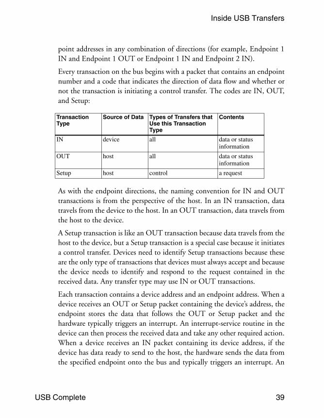
Every transaction on the bus begins with a packet that contains an endpointnumber and a code that indicates the direction of data flow and whether ornot the transaction is initiating a control transfer. The codes are IN, OUT,and Setup:
As with the endpoint directions, the naming convention for IN and OUTtransactions is from the perspective of the host. In an IN transaction, datatravels from the device to the host. In an OUT transaction, data travels fromthe host to the device.
A Setup transaction is like an OUT transaction because data travels from thehost to the device, but a Setup transaction is a special case because it initiatesa control transfer. Devices need to identify Setup transactions because theseare the only type of transactions that devices must always accept and becausethe device needs to identify and respond to the request contained in thereceived data. Any transfer type may use IN or OUT transactions.
Each transaction contains a device address and an endpoint address. When adevice receives an OUT or Setup packet containing the device’s address, theendpoint stores the data that follows the OUT or Setup packet and thehardware typically triggers an interrupt. An interrupt-service routine in thedevice can then process the received data and take any other required action.When a device receives an IN packet containing its device address, if thedevice has data ready to send to the host, the hardware sends the data fromthe specified endpoint onto the bus and typically triggers an interrupt. An
Transaction Type
Source of Data Types of Transfers that Use this Transaction Type
Contents
IN device all data or status information
OUT host all data or status information
Setup host control a request

Chapter 2
40 USB Complete
interrupt-service routine in the device can then do whatever is needed to getready for the next IN transaction.
Pipes: Connecting Endpoints to the HostBefore a transfer can occur, the host and device must establish a pipe. A USBpipe is an association between a device’s endpoint and the host controller’ssoftware.
The host establishes pipes during enumeration. If the device is removedfrom the bus, the host removes the no-longer-needed pipes. The host mayalso request new pipes or remove unneeded pipes at other times by request-ing an alternate configuration or interface for a device. Every device has aDefault Control Pipe that uses Endpoint 0.
The configuration information received by the host includes an endpointdescriptor for each endpoint that the device wants to use. Each endpointdescriptor is a block of information that tells the host what it needs to knowabout the endpoint in order to communicate with it. The informationincludes the endpoint address, the type of transfer to use, the maximum sizeof data packets, and, when appropriate, the desired interval for transfers.
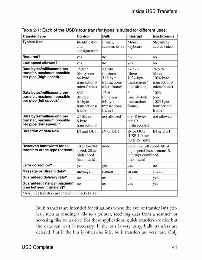
Types of TransfersUSB is designed to handle many types of peripherals with varying require-ments for transfer rate, response time, and error correcting. The four typesof data transfers each handle different needs, and a device can support thetransfer types that are best suited for its purpose. Table 2-1 summarizes thefeatures and uses of each transfer type.
Control transfers are the only type that have functions defined by the USBspecification. Control transfers enable the host to read information about adevice, set a device’s address, and select configurations and other settings.Control transfers may also send vendor-specific requests that send andreceive data for any purpose. All USB devices must support control trans-fers.
Inside USB Transfers
USB Complete 41
Bulk transfers are intended for situations where the rate of transfer isn’t crit-ical, such as sending a file to a printer, receiving data from a scanner, oraccessing files on a drive. For these applications, quick transfers are nice butthe data can wait if necessary. If the bus is very busy, bulk transfers aredelayed, but if the bus is otherwise idle, bulk transfers are very fast. Only
Table 2-1: Each of the USB’s four transfer types is suited for different uses.Transfer Type Control Bulk Interrupt Isochronous
Typical Use Identification and configuration
Printer, scanner, drive
Mouse, keyboard
Streaming audio, video
Required? yes no no no
Low speed allowed? yes no yes no
Data bytes/millisecond per transfer, maximum possible per pipe (high speed).*
15,872 (thirty-one 64-byte transactions/microframe)
53,248 (thirteen 512-byte transactions/microframe)
24,576 (three 1024-byte transactions/microframe)
24,576 (three 1024-byte transactions/microframe)
Data bytes/millisecond per transfer, maximum possible per pipe (full speed).*
832 (thirteen 64-byte transactions/frame)
1216 (nineteen 64-byte transactions/frame)
64(one 64-byte transaction/frame)
1023(one 1023-byte transaction/frame)
Data bytes/millisecond per transfer, maximum possible per pipe (low speed).*
24 (three 8-byte transactions)
not allowed 0.8 (8 bytes per 10 milliseconds)
not allowed
Direction of data flow IN and OUT IN or OUT IN or OUT (USB 1.0 sup-ports IN only)
IN or OUT
Reserved bandwidth for all transfers of the type (percent)
10 at low/full speed, 20 at high speed (minimum)
none 90 at low/full speed, 80 at high speed (isochronous & interrupt combined, maximum)
Error correction? yes yes yes no
Message or Stream data? message stream stream stream
Guaranteed delivery rate? no no no yes
Guaranteed latency (maximum time between transfers)?
no no yes yes
*Assumes transfers use maximum packet size.

Chapter 2
42 USB Complete
full- and high-speed devices can do bulk transfers. Devices aren’t required tosupport bulk transfers, but a specific device class might require them.
Interrupt transfers are for devices that must receive the host’s or device’sattention periodically. Other than control transfers, interrupt transfers arethe only way that low-speed devices can transfer data. Keyboards and miceuse interrupt transfers to send keypress and mouse-movement data. Inter-rupt transfers can use any speed. Devices aren’t required to support interrupttransfers, but a specific device class might require them.
Isochronous transfers have guaranteed delivery time but no error correcting.Data that might use isochronous transfers incudes audio or video to beplayed in real time. Isochronous is the only transfer type that doesn’t supportautomatic re-transmitting of data received with errors, so occasional errorsmust be acceptable. Only full- and high-speed devices can do isochronoustransfers. Devices aren’t required to support isochronous transfers, but a spe-cific device class might require them.
Stream and Message PipesIn addition to classifying a pipe by the type of transfer it carries, the USBspecification defines pipes as either stream or message, according to whetheror not information travels in one or both directions. Control transfers usebidirectional message pipes; all other transfer types use unidirectional streampipes.
Control Transfers Use Message Pipes
In a message pipe, each transfer begins with a Setup transaction containing arequest. To complete the transfer, the host and device may exchange dataand status information, or the device may just send status information. Eachcontrol transfer has at least one transaction that sends information in eachdirection.
If a device supports a received request, the device takes the requested action.If a device doesn’t support the request, the device responds with a code toindicate that the request isn’t supported.

Inside USB Transfers
USB Complete 43
All Other Transfers Use Stream Pipes
In a stream pipe, the data has no structure defined by the USB specification.The receiving host or device just accepts whatever arrives. The device firm-ware or host software can then process the data in whatever way is appropri-ate for the application.
Of course, even with stream data, the sending and receiving devices willneed to agree on a format of some type. For example, a host application maydefine a code that requests a device to send a series of bytes indicating a tem-perature reading and the time of the reading. Although the host could usecontrol transfers with a vendor-defined Get_Temperature request, interrupttransfers may be preferable because of their guaranteed bandwidth.
Initiating a TransferWhen a device driver in the host wants to communicate with a device, thedriver initiates a transfer. The USB specification defines a transfer as theprocess of making and carrying out a communication request. A transfermay be very short, sending as little as a byte of application data, or verylong, sending the contents of a large file.
A Windows application can open communications with a device using ahandle retrieved using standard API functions. To begin a transfer, an appli-cation may use the handle in calling an API function to request the transferfrom the device’s driver. An application might request to “send the contentsof the file data.txt to the device” or “get the contents of Input Report 1 fromthe device.” When an application requests a transfer, the operating systempasses the request to the appropriate device driver, which in turn passes therequest to other system-level drivers and on to the host controller. The hostcontroller then initiates the transfer on the bus.
For devices in standard classes, a programming language can provide alter-nate ways to access a device. For example, the .NET Framework includesDirectory and File classes for accessing files on drives. A vendor-supplieddriver can also define its own API functions. For example, devices that usecontrollers from FTDI Chip can use FTDI’s D2XX driver, which exposes a

Chapter 2
44 USB Complete
series of functions for setting communications parameters and exchangingdata.
In some cases, a driver is configured to request periodic transfers, and appli-cations can read the retrieved data or provide data to send in these transfers.During enumeration, the operating system initiates transfers. Other trans-fers require an application to request to send or receive data.
Transactions: the Building Blocks of a TransferFigure 2-3 shows the elements of a typical transfer. A lot of the terminologyhere begins to sound the same. There are transfers and transactions, stagesand phases, data transactions and data packets, Status stages and handshake
Figure 2-3: A USB transfer consists of transactions. The transactions in turn contain packets, and the packets contain a packet identifier (PID), PID-check bits, and sometimes additional information.

Inside USB Transfers
USB Complete 45
phases. Data stages have handshake packets and Status stages have datapackets. It can take a while to absorb it all. Table 2-2 lists the elements thatmake up each of the four transfer types and may help in keeping the termsstraight.
Each transfer consists of one or more transactions, and each transaction inturn consists of one, two, or three packets.
The three transaction types are defined by their purpose and direction ofdata flow. Setup transactions send control-transfer requests to a device.OUT transactions send other data or status information to the device. INtransactions send data or status information to the host.
The USB specification defines a transaction as the delivery of service to anendpoint. Service in this case can mean either the host’s sending informationto the device, or the host’s requesting and receiving information from thedevice.
Each transaction includes identifying, error-checking, status, and controlinformation as well as any data to be exchanged. A complete transfer maytake place over multiple frames or microframes, but a transaction must com-plete uninterrupted. No other communication on the bus can break into themiddle of a transaction. Devices thus must be able to respond quickly withrequested data or status information in a transaction. Device firmware typi-cally configures, or arms, an endpoint to respond to received packets, andthe hardware responds to the packets when they arrive.
A transfer with a small amount of data may require just one transaction.Other transfers require multiple transactions with a portion of the data ineach.
Transaction PhasesEach transaction has up to three phases, or parts that occur in sequence:token, data, and handshake. Each phase consists of one or two transmittedpackets. Each packet is a block of information with a defined format. Allpackets begin with a Packet ID (PID) that contains identifying information(shown in Table 2-3). Depending on the transaction, the PID may be fol-

Chapter 2
46 USB Complete
lowed by an endpoint address, data, status information, or a frame number,along with error-checking bits.
In the token phase of a transaction, the host initiates a communication bysending a token packet. The PID indicates the transaction type, such asSetup, IN, OUT, or Start-of-Frame.
In the data phase, the host or device may transfer any kind of information ina data packet. The PID includes a data-toggle or data-sequencing value usedto guard against lost or duplicated data when a transfer has multiple datapackets.
Table 2-2: Each of the four transfer types consists of one or more transactions, with each transaction containing two or three phases. (This table doesn’t show the additional transactions required for the split transactions and PING protocol used in some transfers.)Transfer Type Transactions Phases (packets). Each
downstream, low-speed packet is also preceded by a PRE packet.
Control Setup Stage One transaction Token
Data
Handshake
Data Stage Zero or more transactions (IN or OUT)
Token
Data
Handshake
Status Stage One transaction (opposite direction of transaction(s) in the Data stage or IN if there is no Data stage)
Token
Data
Handshake
Bulk One or more transactions (IN or OUT)
Token
Data
Handshake
Interrupt One or more transactions (IN or OUT)
Token
Data
Handshake
Isochronous One or more transactions (IN or OUT)
Token
Data
Inside USB Transfers
USB Complete 47
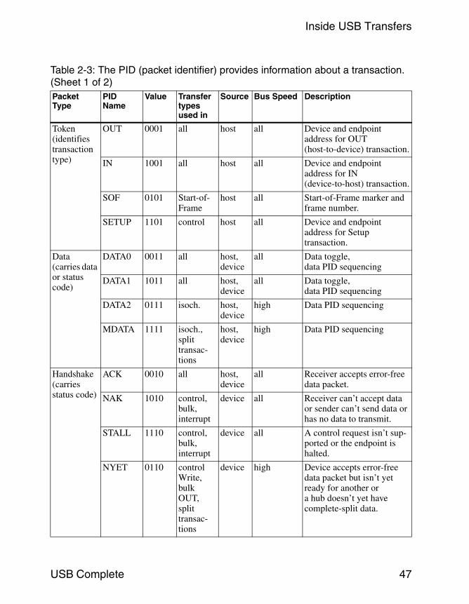
Table 2-3: The PID (packet identifier) provides information about a transaction. (Sheet 1 of 2)Packet Type
PID Name
Value Transfer types used in
Source Bus Speed Description
Token(identifies transaction type)
OUT 0001 all host all Device and endpoint address for OUT (host-to-device) transaction.
IN 1001 all host all Device and endpoint address for IN (device-to-host) transaction.
SOF 0101 Start-of-Frame
host all Start-of-Frame marker and frame number.
SETUP 1101 control host all Device and endpoint address for Setup transaction.
Data(carries data or status code)
DATA0 0011 all host, device
all Data toggle, data PID sequencing
DATA1 1011 all host, device
all Data toggle, data PID sequencing
DATA2 0111 isoch. host, device
high Data PID sequencing
MDATA 1111 isoch., split transac-tions
host, device
high Data PID sequencing
Handshake(carries status code)
ACK 0010 all host, device
all Receiver accepts error-free data packet.
NAK 1010 control, bulk, interrupt
device all Receiver can’t accept data or sender can’t send data or has no data to transmit.
STALL 1110 control, bulk, interrupt
device all A control request isn’t sup-ported or the endpoint is halted.
NYET 0110 control Write, bulk OUT, split transac-tions
device high Device accepts error-free data packet but isn’t yet ready for another or a hub doesn’t yet have complete-split data.

Chapter 2
48 USB Complete
In the handshake phase, the host or device sends status information in ahandshake packet. The PID contains a status code (ACK, NAK, STALL, orNYET). The USB specification sometimes uses the terms status phase andstatus packet to refer to the handshake phase and packet.
The token phase has one additional use. A token packet may carry aStart-of-Frame (SOF) marker, which is a timing reference that the hostsends at 1-millisecond intervals at full speed and at 125-microsecond inter-vals at high speed. This packet also contains a frame number that incre-ments and rolls over on reaching the maximum. The number indicates theframe count, so the eight microframes within a frame all have the samenumber. An endpoint may synchronize to the Start-of-Frame packet or usethe frame count as a timing reference. The Start-of-Frame marker also keepsdevices from entering the low-power Suspend state when there is no otherUSB traffic.
Low-speed devices don’t see the SOF packet. Instead, the hub that thedevice attaches to uses a simpler End-of-Packet (EOP) signal called thelow-speed keep-alive signal, sent once per frame. As the SOF does for
Special PRE 1100 control,interrupt
host full Preamble issued by host to indicate that the next packet is low speed.
ERR 1100 all hub high Returned by a hub to report a low- or full-speed error in a split transaction.
SPLIT 1000 all host high Precedes a token packet to indicate a split transaction.
PING 0100 control Write, bulk OUT
host high Busy check for bulk OUT and control Write datatransactions after NYET.
reserved 0000 – – – For future use.
Table 2-3: The PID (packet identifier) provides information about a transaction. (Sheet 2 of 2)Packet Type
PID Name
Value Transfer types used in
Source Bus Speed Description
Inside USB Transfers
USB Complete 49
full-speed devices, the low-speed keep-alive keeps low-speed devices fromentering the Suspend state.
Of the four special PIDs, one is used only with low-speed devices, one isused only with high-speed devices, and two are used when a low- orfull-speed device’s 2.0 hub communicates at high speed with the host.
The special low-speed PID is PRE, which contains a preamble code thattells hubs that the next packet is low speed. On receiving a PRE PID, thehub enables communications with any attached low-speed devices. On alow- and full-speed bus, the PRE PID precedes all token, data, and hand-shake packets directed to low-speed devices. High-speed buses encode thePRE in the SPLIT packet, rather than sending the PRE separately.Low-speed packets sent by a device don’t require a PRE PID.
The PID used only with high-speed devices is PING. In a bulk or controltransfer with multiple data packets, before sending the second and any sub-sequent data packets, the host may send a PING to find out if the endpointis ready to receive more data. The device responds with a status code.
The SPLIT PID identifies a token packet as part of a split transaction, asexplained later in this chapter. The ERR PID is used only in split transac-tions. A 2.0 hub uses this PID to report an error to the host in a low- orfull-speed transaction. The ERR and PRE PIDs have the same value butwon’t be confused because a hub never sends a PRE to the host or an ERR toa device. Also, ERR is used only on high-speed segments and PRE is neverused on high-speed segments.
Packet Sequences
Every transaction has a token packet. The host is always the source of thispacket, which sets up the transaction by identifying the packet type, thereceiving device and endpoint, and the direction of any data the transactionwill transfer. For low-speed transactions on a full-speed bus, a PRE packetprecedes the token packet. For split transactions, a SPLIT packet precedesthe token packet.
Depending on the transfer type and whether the host or device has informa-tion to send, a data packet may follow the token packet. The direction spec-
Chapter 2
50 USB Complete
ified in the token packet determines whether the host or device sends thedata packet.
In all transfer types except isochronous, the receiver of the data packet (orthe device if there is no data packet) returns a handshake packet containinga code that indicates the success or failure of the transaction. The absence ofan expected handshake packet indicates a more serious error.
Timing Constraints and Guarantees
The allowed delays between the token, data, and handshake packets of atransaction are very short, intended to allow only for cable delays andswitching times plus a brief time to allow the hardware to prepare aresponse, such as a status code, in response to a received packet.
A common mistake in writing firmware is to assume that the firmwareshould wait for an interrupt before providing data to send to the host.Instead, before the host requests the data, the firmware must copy the datato send into the endpoint’s buffer and configure the endpoint to send thedata on receiving an IN token packet. The interrupt occurs after the transac-tion completes, to tell the firmware that the endpoint’s buffer can store datafor the next transaction. If the firmware waits for an interrupt before provid-ing the initial data, the interrupt never happens and no data is transferred.
A single transaction can carry an amount of data up to the maximum packetsize specified for the endpoint. A data packet that is less than the maximumpacket size is a short packet. A transfer with multiple transactions may takeplace over multiple frames or microframes, which don’t have to be contigu-ous. For example, in a full-speed bulk transfer of 512 bytes, the maximumnumber of bytes in a single transaction is 64, so transferring all of the datarequires at least 8 transactions, which may occur in one or more(micro)frames.
Split Transactions
A 2.0 hub communicates with a 2.0 host at high speed unless a 1.x hub liesbetween them. When a low- or full-speed device is attached to a 2.0 hub,the hub converts between speeds as needed. But speed conversion isn’t the

Inside USB Transfers
USB Complete 51
only thing a hub does to manage multiple speeds. High speed is 40 timesfaster than full speed and 320 times faster than low speed. It doesn’t makesense for the entire bus to wait while a hub exchanges low- or full-speed datawith a device.
The solution is split transactions. A 2.0 host uses split transactions whencommunicating with a low- or full-speed device on a high-speed bus. Whatwould be a single transaction at low or full speed usually requires two typesof split transactions: one or more start-split transactions to send informationto the device and one or more complete-split transactions to receive infor-mation from the device. The exception is isochronous OUT transactions,which don’t use complete-split transactions because the device has nothingto send.
Even though they require more transactions, split transactions make betteruse of bus time because they minimize the amount of time spent waiting fora low- or full-speed device to transfer data. The USB 2.0 host controller andthe closest 2.0 hub upstream from the low- or full-speed device are entirelyresponsible for performing split transactions. The device and its firmwaredon’t have to know or care whether the host is using split transactions. Thetransactions at the device are identical whether the host is using split trans-actions or not. At the host, device drivers and application software don’thave to know or care whether the host is using split transactions because theprotocol is handled at a lower level. Chapter 15 has more about how splittransactions work.
Ensuring that Transfers Are SuccessfulUSB transfers use handshaking and error-checking to help ensure that datagets to its destination as quickly as possible and without errors.
HandshakingLike other interfaces, USB uses status and control, or handshaking, infor-mation to help to manage the flow of data. In hardware handshaking, dedi-cated lines carry the handshaking information. An example is the RTS and

Chapter 2
52 USB Complete
CTS lines in the RS-232 interface. In software handshaking, the same linesthat carry the data also carry handshaking codes. An example is the XONand XOFF codes transmitted on the data lines in RS-232 links.
USB uses software handshaking. A code indicates the success or failure of alltransactions except in isochronous transfers. In addition, in control trans-fers, the Status stage enables a device to report the success or failure of anentire transfer.
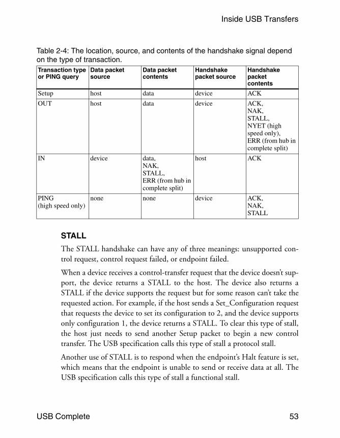
Handshaking signals transmit in the handshake or data packet. The definedstatus codes are ACK, NAK, STALL, NYET, and ERR. The absence of anexpected handshake code indicates a more serious error. In all cases, theexpected receiver of the handshake uses the information to help decide whatto do next. Table 2-4 shows the status indicators and where they transmit ineach transaction type.
ACK
ACK (acknowledge) indicates that a host or device has received data withouterror. Devices must return ACK in the handshake packets of Setup transac-tions when the token and data packets were received without error. Devicesmay also return ACK in the handshake packets of OUT transactions. Thehost returns ACK in the handshake packets of IN transactions.
NAK
NAK (negative acknowledge) means the device is busy or has no data toreturn. If the host sends data at a time when the device is too busy to acceptthe data, the device returns a NAK in the handshake packet. If the hostrequests data from the device when the device has nothing to send, thedevice returns a NAK in the data packet. In either case, NAK indicates atemporary condition, and the host retries later.
Hosts never send NAK. Isochronous transactions don’t use NAK becausethey have no handshake packet for returning a NAK. If a device or the hostdoesn’t receive transmitted isochronous data, it’s gone.
Inside USB Transfers
USB Complete 53
STALL
The STALL handshake can have any of three meanings: unsupported con-trol request, control request failed, or endpoint failed.
When a device receives a control-transfer request that the device doesn’t sup-port, the device returns a STALL to the host. The device also returns aSTALL if the device supports the request but for some reason can’t take therequested action. For example, if the host sends a Set_Configuration requestthat requests the device to set its configuration to 2, and the device supportsonly configuration 1, the device returns a STALL. To clear this type of stall,the host just needs to send another Setup packet to begin a new controltransfer. The USB specification calls this type of stall a protocol stall.
Another use of STALL is to respond when the endpoint’s Halt feature is set,which means that the endpoint is unable to send or receive data at all. TheUSB specification calls this type of stall a functional stall.
Table 2-4: The location, source, and contents of the handshake signal depend on the type of transaction.Transaction type or PING query
Data packet source
Data packet contents
Handshake packet source
Handshake packet contents
Setup host data device ACK
OUT host data device ACK,NAK,STALL, NYET (high speed only),ERR (from hub in complete split)
IN device data,NAK,STALL,ERR (from hub in complete split)
host ACK
PING (high speed only)
none none device ACK,NAK, STALL

Chapter 2
54 USB Complete
Bulk and interrupt endpoints must support the functional stall. Althoughcontrol endpoints may also support this use of STALL, it’s not recom-mended. A control endpoint in a functional stall must continue to respondnormally to other requests related to controlling and monitoring the stallcondition. And an endpoint that is capable of responding to these requests isclearly capable of communicating and shouldn’t be stalled. Isochronoustransactions don’t use STALL because they have no handshake packet forreturning the STALL.
On receiving a functional STALL, the host drops all pending requests to thedevice and doesn’t resume communications until the host has sent a success-ful request to clear the Halt feature on the device. Hosts never send STALL.
NYET
Only high-speed devices use NYET, which stands for not yet. High-speedbulk and control transfers have a protocol that enables the host to find outbefore sending data if a device is ready to receive the data. At full and lowspeeds, when the host wants to send data in a control, bulk, or interrupttransfer, the host sends the token and data packets and receives a reply fromthe device in the handshake packet of the transaction. If the device isn’tready for the data, the device returns a NAK and the host tries again later.This can waste a lot of bus time if the data packets are large and the device isoften not ready.
High-speed bulk and control transactions with multiple data packets have abetter way. After receiving a data packet, a device endpoint can return aNYET handshake, which says that the endpoint accepted the data but is notyet ready to receive another data packet. When the host thinks the devicemight be ready, the host can send a PING token packet, and the endpointreturns either an ACK to indicate the device is ready for the next data packetor NAK or STALL if the device isn’t ready. Sending a PING is more efficientthan sending the entire data packet only to find out the device wasn’t readyand having to resend later. Even after responding to a PING or OUT withACK, an endpoint is allowed to return NAK on receiving the data packetthat follows but should do so rarely. The host then tries again with anotherPING. The use of PING by the host is optional.

Inside USB Transfers
USB Complete 55
A 2.0 hub may also use NYET in complete-split transactions. Hosts andlow- and full-speed devices never send NYET.
ERR
The ERR handshake is used only by high-speed hubs in complete-splittransactions. ERR indicates the device didn’t return an expected handshakein the transaction the hub is completing with the host.
No Response
Another type of status indication occurs when the host or a device expects toreceive a handshake but receives nothing. This lack of response can occur ifthe receiver’s error-checking calculation detected an error. On receiving noresponse, the sender knows that it should try again. If if multiple tries fail,the sender can take other action. (If the receiver ACKs the data but doesn’tuse it, the problem is probably in the data-toggle value.)
Reporting the Status of Control TransfersIn addition to reporting the status of transactions, the same ACK, NAK,and STALL codes report the success or failure of complete control transfers.An additional status code is a zero-length data packet (ZLP), which reportssuccessful completion of a control transfer. A transaction with a zero-lengthdata packet is a transaction whose Data phase consists of a Data PID anderror-checking bits but no data. Table 2-5 shows the status indicators forcontrol transfers.
For control Write transfers, where the device receives data in the Data stage,the device returns the transfer’s status in the data packet of the Status stage.A zero-length data packet means the transfer was successful, a STALL indi-cates that the device can’t complete the transfer, and a NAK indicates thatthe device isn’t ready to complete the transfer. The host returns an ACK inthe handshake packet of the Status stage to indicate that the host receivedthe response.
For control Read transfers, where the host receives data in the Data stage,the device returns the status of the transfer in the handshake packet of the

Chapter 2
56 USB Complete
Status stage. The host normally waits to receive all of the packets in the Datastage, then returns a zero-length data packet in the Status stage. The deviceresponds with ACK, NAK, or STALL. However, if the host begins the Sta-tus stage before all of the requested data packets have been sent, the devicemust abandon the Data stage and return a status code.
Error CheckingThe USB specification spells out hardware requirements that ensure thaterrors due to line noise will be rare. Still, there is a chance that a noise glitchor unexpectedly disconnected cable could corrupt a transmission. For thisreason, USB packets include error-checking bits that enable a receiver toidentify just about any received data that doesn’t match what was sent. Inaddition, for transfers that require multiple transactions, a data-toggle valuekeeps the transmitter and receiver synchronized to ensure that no transac-tions are missed entirely.
Error-checking Bits
All token, data, and Start-of-Frame packets include bits for use inerror-checking. The bit values are calculated using a mathematical algorithmcalled the cyclic redundancy check (CRC). The USB specification explains
Table 2-5: Depending on the direction of the Data stage, the status information for a control transfer may be in the data or handshake packet of the Status stage.Transfer Type and Direction
Status Stage Direction
Status stage’s data packet
Status stage’s hand-shake packet
Control Write (Host sends data to device or no Data stage)
IN Device sends status:zero-length data packet (success),NAK (busy), orSTALL (failed)
Host returns ACK
Control Read(Device sends data to host)
OUT Host sends zero-length data packet
Device sends status:ACK (success),NAK (busy), orSTALL (failed)

Inside USB Transfers
USB Complete 57
how the CRC is calculated. The hardware handles the calculations, whichmust be done quickly to enable the device to respond appropriately.
The CRC is applied to the data to be checked. The transmitting device per-forms the calculation and sends the result along with the data. The receivingdevice performs the identical calculation on the received data. If the resultsmatch, the data has arrived without error and the receiving device returns anACK. If the results don’t match, the receiving device sends no handshake.The absence of the expected handshake tells the sender to retry.
Typically, the host tries a total of three times, but the USB specification givesthe host some flexibility in determining the number of retries. On giving up,the host informs the driver of the problem.
The PID field in token packets uses a simpler form of error checking. Thelower four bits in the field are the PID, and the upper four bits are its com-plement. The receiver can check the integrity of the PID by complementingthe upper four bits and ensuring that they match the PID. If not, the packetis corrupted and is ignored.
The Data Toggle
In transfers that require multiple transactions, the data-toggle value canensure that no transactions are missed by keeping the transmitting andreceiving devices synchronized. The data-toggle value is included in the PIDfield of the token packets for IN and OUT transactions. DATA0 is a code of0011, and DATA1 is 1011. In controller chips, a register bit often indicatesthe data-toggle state, so the data-toggle value is often referred to as thedata-toggle bit. Each endpoint maintains its own data toggle.
Both the sender and receiver keep track of the data toggle. A Windows hosthandles the data toggles without requiring any user programming. Somedevice controller chips also handle the data toggles completely automati-cally, while others require some firmware control. If you’re debugging adevice where it appears that the proper data is transmitting on the bus butthe receiver is discarding the data, chances are good that the device isn’tsending or expecting the correct data toggle.

Chapter 2
58 USB Complete
When the host configures a device on power up or attachment, the host anddevice each set their data toggles to DATA0 for all except some high-speedisochronous endpoints. On detecting an incoming data packet, the host ordevice compares the state of its data toggle with the received data toggle. Ifthe values match, the receiver toggles its value and returns an ACK hand-shake packet to the sender. The ACK causes the sender to toggle its value forthe next transaction.
The next received packet in the transfer should contain a data toggle ofDATA1, and again the receiver toggles its bit and returns an ACK. The datatoggle continues to alternate until the transfer completes. (An exception iscontrol transfers, where the Status stage always uses DATA1.)
If the receiver is busy and returns a NAK, or if the receiver detects corrupteddata and returns no response, the sender doesn’t toggle its bit and insteadtries again with the same data and data toggle.
If a receiver returns an ACK but for some reason the sender doesn’t see theACK, the sender will think that the receiver didn’t get the data and will tryagain using the same data and data-toggle bit. In this case, the receiver of therepeated data doesn’t toggle the data toggle and ignores the data but returnsan ACK. The ACK re-synchronizes the data toggles. The same thing hap-pens if the sender mistakenly sends the same data toggle twice in a row.
Control transfers always use DATA0 in the Setup stage, use DATA1 in thefirst transaction of the Data stage, toggle the bit in any additional Data-stagetransactions, and use DATA1 in the Status stage. Bulk endpoints toggle thebit in every transaction, resetting the data toggle only after completing aSet_Configuration, Set_Interface, or Clear_Feature(ENDPOINT HALT)request. Interrupt endpoints can behave the same as bulk endpoints. Or aninterrupt IN endpoint can toggle its data toggle in each transaction withoutchecking for the host’s ACKs, at the risk of losing some data. Full-speed iso-chronous transfers always use DATA0. Isochronous transfers can’t use thedata toggle to correct errors because there is no handshake packet for return-ing an ACK or NAK and no time to resend missed data.
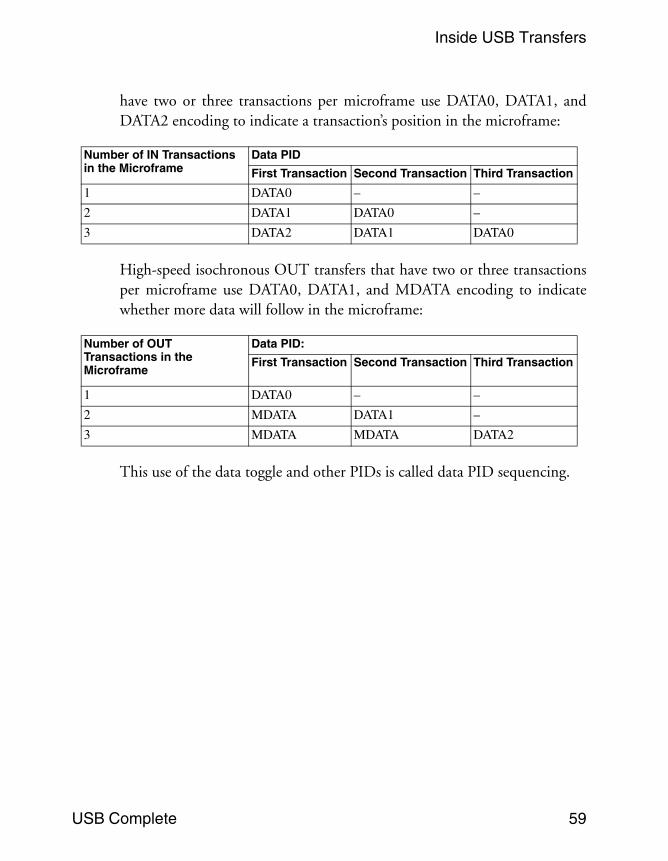
Some high-speed isochronous transfers use DATA0, DATA1, and additionalPIDs of DATA2 and MDATA. High-speed isochronous IN transfers that
Inside USB Transfers
USB Complete 59
have two or three transactions per microframe use DATA0, DATA1, andDATA2 encoding to indicate a transaction’s position in the microframe:
High-speed isochronous OUT transfers that have two or three transactionsper microframe use DATA0, DATA1, and MDATA encoding to indicatewhether more data will follow in the microframe:
This use of the data toggle and other PIDs is called data PID sequencing.
Number of IN Transactions in the Microframe
Data PID
First Transaction Second Transaction Third Transaction
1 DATA0 – –
2 DATA1 DATA0 –
3 DATA2 DATA1 DATA0
Number of OUT Transactions in the Microframe
Data PID:
First Transaction Second Transaction Third Transaction
1 DATA0 – –
2 MDATA DATA1 –
3 MDATA MDATA DATA2

Chapter 2
60 USB Complete