insitu: sketching architectural designs in context
TRANSCRIPT
ACM Reference FormatPaczkowski, P., Kim, M., Morvan, Y., Dorsey, J., Rushmeier, H., O’Sullivan, C. 2011. InSitu: Sketching Architectural Designs in Context. ACM Trans. Graph. 30, 6, Article 182 (December 2011), 10 pages. DOI = 10.1145/2024156.2024216 http://doi.acm.org/10.1145/2024156.2024216.
Copyright NoticePermission to make digital or hard copies of part or all of this work for personal or classroom use is granted without fee provided that copies are not made or distributed for profi t or direct commercial advantage and that copies show this notice on the fi rst page or initial screen of a display along with the full citation. Copyrights for components of this work owned by others than ACM must be honored. Abstracting with credit is permitted. To copy otherwise, to republish, to post on servers, to redistribute to lists, or to use any component of this work in other works requires prior specifi c permission and/or a fee. Permissions may be requested from Publications Dept., ACM, Inc., 2 Penn Plaza, Suite 701, New York, NY 10121-0701, fax +1 (212) 869-0481, or [email protected].© 2011 ACM 0730-0301/2011/12-ART182 $10.00 DOI 10.1145/2024156.2024216 http://doi.acm.org/10.1145/2024156.2024216
Insitu: Sketching Architectural Designs in Context
Patrick Paczkowski† Min H. Kim† Yann Morvan§ Julie Dorsey† Holly Rushmeier† Carol O’Sullivan§
Yale University† Trinity College Dublin§
Elevation data
Photographs
Site plan
Insitu
+
(a) (b) (c)
Aerial map
Interface
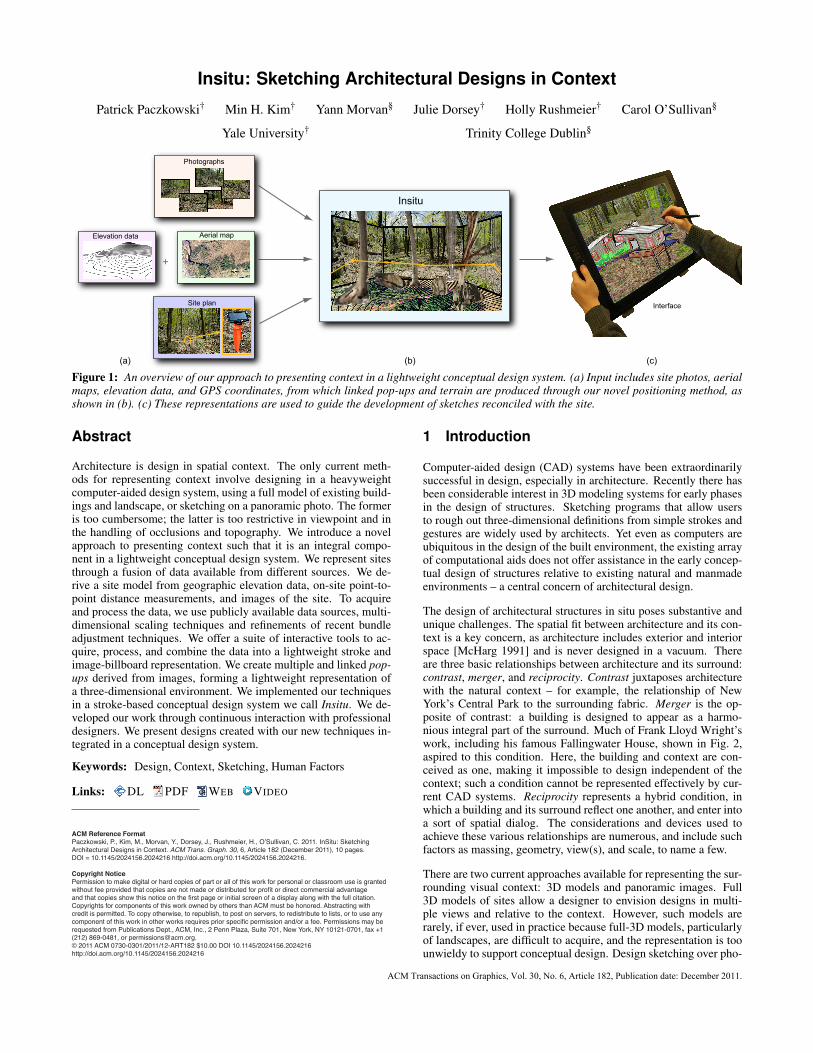
Figure 1: An overview of our approach to presenting context in a lightweight conceptual design system. (a) Input includes site photos, aerialmaps, elevation data, and GPS coordinates, from which linked pop-ups and terrain are produced through our novel positioning method, asshown in (b). (c) These representations are used to guide the development of sketches reconciled with the site.
Abstract
Architecture is design in spatial context. The only current meth-ods for representing context involve designing in a heavyweightcomputer-aided design system, using a full model of existing build-ings and landscape, or sketching on a panoramic photo. The formeris too cumbersome; the latter is too restrictive in viewpoint and inthe handling of occlusions and topography. We introduce a novelapproach to presenting context such that it is an integral compo-nent in a lightweight conceptual design system. We represent sitesthrough a fusion of data available from different sources. We de-rive a site model from geographic elevation data, on-site point-to-point distance measurements, and images of the site. To acquireand process the data, we use publicly available data sources, multi-dimensional scaling techniques and refinements of recent bundleadjustment techniques. We offer a suite of interactive tools to ac-quire, process, and combine the data into a lightweight stroke andimage-billboard representation. We create multiple and linked pop-ups derived from images, forming a lightweight representation ofa three-dimensional environment. We implemented our techniquesin a stroke-based conceptual design system we call Insitu. We de-veloped our work through continuous interaction with professionaldesigners. We present designs created with our new techniques in-tegrated in a conceptual design system.
Keywords: Design, Context, Sketching, Human Factors
Links: DL PDF WEB VIDEO
1 Introduction
Computer-aided design (CAD) systems have been extraordinarilysuccessful in design, especially in architecture. Recently there hasbeen considerable interest in 3D modeling systems for early phasesin the design of structures. Sketching programs that allow usersto rough out three-dimensional definitions from simple strokes andgestures are widely used by architects. Yet even as computers areubiquitous in the design of the built environment, the existing arrayof computational aids does not offer assistance in the early concep-tual design of structures relative to existing natural and manmadeenvironments – a central concern of architectural design.
The design of architectural structures in situ poses substantive andunique challenges. The spatial fit between architecture and its con-text is a key concern, as architecture includes exterior and interiorspace [McHarg 1991] and is never designed in a vacuum. Thereare three basic relationships between architecture and its surround:contrast, merger, and reciprocity. Contrast juxtaposes architecturewith the natural context – for example, the relationship of NewYork’s Central Park to the surrounding fabric. Merger is the op-posite of contrast: a building is designed to appear as a harmo-nious integral part of the surround. Much of Frank Lloyd Wright’swork, including his famous Fallingwater House, shown in Fig. 2,aspired to this condition. Here, the building and context are con-ceived as one, making it impossible to design independent of thecontext; such a condition cannot be represented effectively by cur-rent CAD systems. Reciprocity represents a hybrid condition, inwhich a building and its surround reflect one another, and enter intoa sort of spatial dialog. The considerations and devices used toachieve these various relationships are numerous, and include suchfactors as massing, geometry, view(s), and scale, to name a few.
There are two current approaches available for representing the sur-rounding visual context: 3D models and panoramic images. Full3D models of sites allow a designer to envision designs in multi-ple views and relative to the context. However, such models arerarely, if ever, used in practice because full-3D models, particularlyof landscapes, are difficult to acquire, and the representation is toounwieldy to support conceptual design. Design sketching over pho-
ACM Transactions on Graphics, Vol. 30, No. 6, Article 182, Publication date: December 2011.

tographic panoramas, either on paper or by computer, is often useddue to the intuitive interface. However, these sketches cannot eas-ily be reconciled into a 3D form, and testing the compatibility oflocations in the site is challenging, if not impossible. Moreover,this approach is very inadequate when complex topographic varia-tions are involved, and sketching on a photograph does not allow forocclusions or multiple views. At best, it can only support the juxta-position approach, described above – and only for a single view.
Figure 2: A design in whichthe building and context aremerged is Frank Lloyd Wright’sFallingwater [Sxenko 2007].
A system to support design-ing relative to context needsto be able to incorporate con-straints and features imposedby the existing setting, whileallowing free creative exper-imentation. The key imped-iment to designing relativeto context is the inability topresent a complex setting ina form that is amenable toconceptual design.
In this paper, we present asuite of techniques to repre-sent context – including ter-rain information, built struc-tures, and natural features –in a manner consistent withearly conceptual design. Weimplement this representa-tion in a sketch-based systemthat we call Insitu. Build-ing on previous 3D stroke-based sketching systems, such asHarold [Cohen et al. 2000], 3D6B [Kallio 2005], and Mental Can-vas [Dorsey et al. 2007], Insitu allows a user to enter strokes on 2Dplanes, which can be positioned in 3D space to lay out a design.Fig. 1(a) shows the elements of our context visualization method;Fig. 1(b) presents our context representation; Fig. 1(c) displays oursystem application with an LCD screen tablet. We make the fol-lowing contributions:
• A novel approach to representing a complex site, which en-ables interactive, conceptual design in situ;
• The integration of this representation into a stroke-basedsketching system;
• A method for fusing data from different sources – includ-ing geographic elevation data, on-site point-to-point distancemeasurements, and images of the site – into a common coor-dinate system;
• A discussion about the iterative development of a design sys-tem, based on collaboration between computer scientists anddesigners.
2 Related Work
We are interested in enabling designers to sketch within the visualcontext of a site. Understanding context is even more central todesign than the ability to produce drawings of design alternatives[Bilda and Gero 2005]. In conventional practice, designers eitherdraw the context within their design sketches, or use acetates tosketch over photographs or on-site drawings. In this section wereview previous work on sketching systems for early conceptualdesign, architectural design in context, site modeling with pho-tographs and publicly available resources for site modeling.
Sketching Current CAD software that is capable of preparing fi-nal building plans is not suitable for the early phases of design[Chrabin et al. 2003]. To address this issue, simpler and more
intuitive systems have been developed for early design, such asSESAME [Oh et al. 2006] and Google SketchUp [2011]. Whilesimpler than full CAD packages, these are still solid modeling sys-tems. Creating a solid model is fundamentally different from creat-ing a drawing of a particular view of a design.
In the early phases, a designer works by, as Schon put it, “hav-ing a conversation with the drawing” [Schon 1983]. Free-handsketching on paper remains the preferred medium. Since Suther-land’s [1964] groundbreaking work, numerous computer interfaceshave been proposed to let designers sketch to develop models onthe computer [Jorge and Samavati 2011].
A computer allows 3D rather than 2D sketching. The ability tochange viewpoint dynamically has been shown to enhance the per-ception of 3D structures compared to the mental merging of staticviews [Sollenberger and Milgram 1993; Sando et al. 2009]. Re-cent work has aimed to marry the computer’s ability to process3D information with free-hand sketching. Particularly suited toearly design are sketch-based systems that allow the evolution ofdesigns from strokes placed in 3D, rather than as sets of 3D solidshapes. In stroke-based systems, such as 3D6B [Kallio 2005] andMental Canvas [Dorsey et al. 2007], the user begins by creatingsketches naturally in 2D, and then is allowed to pull apart and po-sition the strokes in the 2D sketches to begin to suggest a 3D form.Kalnins et al. [2002] developed a sketching system incorporatingnon-photorealistic rendering (NPR) style strokes in 3D. Just likea blank sketchpad, these systems focus on letting designers startfrom scratch. Tsang et al. [2004] introduced an image-aided sketch-ing interface system, where 2D images are overlaid to guide userstrokes. The system then produces a coarse structured 3D wire-frame model. However, these previous systems do not provide amechanism for modeling the site environments. We build on thesestroke-based systems, and in particular take the style of user inter-actions used in Mental Canvas as the model for our system.
Architectural Design in Context The relationship between ar-chitecture and its context is a perennial issue [McHarg 1991]. Ithas become common to use computers to organize contextual doc-uments [Aliakseyeu et al. 2006] for reference during the design pro-cess. Documentation of contextual information can be gathered viacomputer from public sources on the Internet [Stellingwerff 2007].We build on this work by using publicly available geographic datain creating context.
Chrabin et al. [2003] investigated the use of currently available soft-ware to provide visual context in the 3D design space, rather thanas peripheral documents used as reference. They found that com-modity CAD software created for detailed final modeling is not ap-propriate in the early stages of design. They stress the importanceof simple interfaces and representations for early design phases. Inthe field of landscape architectural design, Rekittke and Paar [2008]also investigated types of context representation and found it unde-sirable to mix highly detailed photorealistic representations withincomplete designs. The type of representation used for the exist-ing context should match the representation of the evolving design.We build on this insight by creating representations of site environ-ments consistent with a stroke-based sketching system for design.
Modeling from Photographs There has been considerable recentwork in the areas of computer vision and computer graphics to cre-ate digital representations of complex natural scenes by processingsets of photographs. This work ranges from organizing sets of pho-tographs in 3D via estimating camera positions with bundling tech-niques [Snavely et al. 2006] to the reconstruction of entire detailedstructures from images [Pollefeys et al. 2004]. Even organized in3D space, photograph collections are difficult to use to insert novel3D structures that would be partially occluded in many of the pho-tographs. Reconstructed detailed structures cannot always be reli-
182:2 • P. Paczkowski et al.
ACM Transactions on Graphics, Vol. 30, No. 6, Article 182, Publication date: December 2011.

Input:user site survey,
photos, map, GPS
Importan aerial map/elevation data
Importbundle
photographs
Createpop-ups
Stroke-basedsketchingin context
Output:conceptual
sketch design
Building context
Insitu
Figure 3: Schematic illustration of our context-aware sketching system workflow. First, information about the site is gathered by a user in theform of photographs, an aerial map, GPS positions, etc. Then, the ground information from an aerial map/elevation data are imported intothe system to form the base of the virtual site. Next, photographs are bundle-adjusted and imported into the system, which yields a lightweightrepresentation, consisting of pop-ups positioned in space. This context representation and visualization are used to guide the development ofstroke-based sketching of designs in context and reconciled with the site.
ably produced (particularly for natural objects, such as trees), andare computationally demanding for interactive design.
The space between just images and full 3D structures has been ex-plored to some extent. Recognizing that full 3D cannot be recov-ered, Thormahlen and Seidel [2008] used the camera positions andrough geometry recovered using bundler techniques to generate or-thoimages to guide design. In an even simpler approach, Lau etal. [2010] developed a system for sketches and markups on a sin-gle photo to define a 3D object. Lee et al. [2008] introduced anapplication to reconstruct incomplete 3D models from architecturaldrawings with user interaction. These approaches are suitable formodeling individual objects, but not for modeling an environment.
An alternative approach to using photographs to produce alightweight model of a 3D environment is the generation of photopop-ups. Photo pop-ups combine coarse geometry (planes), tex-tures and transparency. Hoiem et al. [2005] proposed a fully auto-matic approach to create a pop-up from a photograph. Computers,however, are still no match for humans at scene understanding, andintervention is necessary to correct failure cases. A fully automatedapproach may also fail to capture the features of concern to a de-signer. The work of Ventura et al. [2009] is closest to our purpose.Their main contribution consists of an interface for specifying oc-clusion boundaries. We build on this work by extending the userinput for pop-up creation.
An individual image pop-up is only a 2.5D representation of ascene. A full 3D representation is needed for architectural design.To address this need, we use multiple linked pop-ups. To positionthe pop-ups, we use bundle adjustment to position the original pho-tographs. These positions are refined by a local site survey tech-nique, and are tied to global positioning system (GPS) coordinatesusing publicly available resources.
Publicly Available Resources Systems such as Bing Maps andGoogle Earth have made rich geographic datasets including aerialphotographs easily available to the general public. This data can beused in modeling sites. For example, Google SketchUp 8 [2011]makes it possible to import aerial photographs and city buildingsas blocks to use as a site model. However, aerial photographs andblock building models alone are not suitable for modeling undevel-oped sites with natural features such as rocks and trees. Further-more, the SketchUp system does not accommodate stroke-basedmodeling for conceptual design of free-form shapes.
To model local sites, many devices that provide GPS coordinatesare available at a reasonable cost. A GPS device receives two datavalues from available satellites: the satellite location and the timeof that location. From this data, the device calculates pairwisedistances between itself and multiple satellites; triangulation thenyields latitude/longitude coordinates of the device. Generally, 6-8satellites are used for common GPS navigation systems. A high-
end professional GPS device uses ∼15 satellites to provide higheraccuracy [Leica 2011]. In theory, a GPS device could be used toproduce a site survey. However, the accuracy of consumer-gradesatellite navigation devices is coarse and inadequate for architec-tural applications. Therefore, we enhance the accuracy of the com-modity GPS measurements with multi-dimensional scaling.
3 Site Representation
We present a new method for capturing a site environment to beused as context in early conceptual design. Our approach consistsof modeling the site topography using local measurements and GPScoordinates, representing site features by creating and positioningmultiple image pop-ups positioned relative to the topography, andimporting this representation into a compatible stroke-based sketchsystem. Fig. 3 summarizes our workflow.
3.1 Site Topography
Our goal is to model the local site topography with enough detail tobe able to easily locate existing buildings and to support the concep-tual design of new buildings. Using aerial photographs from BingMaps or Google Earth does not generally provide adequate detail,while using range scans to create dense 3D models is inappropriatefor use with a conceptual design system. One approach to obtaininga sufficiently-detailed model in universal geographic coordinates isto take measurements at site landmarks using a commodity GPSdevice, such as an iPhone camera, or a vehicle navigation system,e.g. TomTom. However, these systems have poor accuracy relativeto the needs of an architectural site plan, with errors on the order of∼6m (GPS device) to ∼9m (iPhone) [Zandbergen 2009].
We introduce a method inspired by [Rushmeier et al. 2007], as wellas research in Sensor Network Localization [Zhou et al. 2009], tomeasure the absolute geographical coordinates of feature objects ina site more accurately than using raw GPS coordinates. We use asimple system of stakes that we physically position on the site, sim-ilar to stakes used by land surveyors. We create a local model of thetopography defined by these stakes by taking linear measurementsbetween stakes and using this to refine coarse GPS measurements.
Relative Positioning We take linear distance measurements be-tween all pairs of N stakes. We then use multi-dimensional scal-ing (MDS) [Borg and Groenen 2005] to find the 3D positions ofthese points (see Fig. 5 (a)). From the given measurements δi, j,i, j ∈ N, we estimate the unknown three-dimensional coordinatesof N points x = x1, ...,xN ∈ R3, by minimizing the following ob-jective function f (x) using nonmetric MDS with Kruskal’s stresscriterion:
f (x) = ∑i< j
(∥∥xi− x j∥∥
2−δi, j)2.
Insitu: Sketching Architectural Designs in Context • 182:3
ACM Transactions on Graphics, Vol. 30, No. 6, Article 182, Publication date: December 2011.

(a) (b)
Figure 4: Stake positions with GPS measurements (yellow circles)and dissimilarity measurements (yellow lines) in a rural site (a),with a zoomed-in example stake shown in (b).
1
7
4
6
2
3
8
5
Multi-dimensional scaling (relative locations)
(b)(a)
(d)(c)
6
7
1
5 8
3
2
4
Coarse GPS positions(latitude/longitude)
Standard UTM coordinates(X/Y/Elevation)
1
7
4
6
2
3
8
5
Bundle photographs
1
7
4
6
2
3
8
5
Figure 5: We measure pairwise distances between stakes (a) to es-timate their relative XYZ coordinates with multi-dimensional scal-ing. These coordinates are used to refine coarse GPS measurementsof the stakes (b), resulting in more accurate global coordinates (c).The stakes are then used as anchor points to map relative positionsof bundled photographs (d) into the UTM coordinate space.
Global Coordinate System The result of computing this mini-mum is a set of three-dimensional coordinates x in a local co-ordinate system that we wish to relate to global geographic coor-dinates in the standard Universal Transverse Mercator (UTM) co-ordinate system. To do this, we take GPS measurements of thestakes with a commodity device, and query the US Geological Sur-vey (USGS) seamless data warehouse [Gesch 2007] for correspond-ing elevation measurements, giving us rough standard coordinatesy = y1, ...,yN ∈ R3. We then estimate a 4-by-4 affine transform Aby minimizing the following objective function using least squares:g(A) = ‖y−Ax‖2
2 . The transformed 3D coordinates Ax shouldhave a higher accuracy than the commodity GPS measurements. Inaddition, this data set includes elevation at a higher accuracy. Notethat our use of MDS to refine GPS data differs from the work ofZhou et al. [2009]; they use MDS to estimate ground-truth (2D)sensor node locations for testing the accuracy of standalone GPS.
We merge the refined 3D coordinates with USGS-provided ortho-imagery (aerial photographs) and elevation data of the region, givenin the form of a geo-referenced bitmap file. Other resources fromGoogle Earth or Bing Maps could be employed as replacements.The elevation data can be used to create a surface that is suitablefor rendering through the standard graphics pipeline [Warmerdam2010]. We convert the elevation data into a height-field terrainmesh, for hidden surface and line removal and user-prompted alti-tude queries. See Fig. 6 (a) for an example of a landscape site.
3.2 Modeling with Photographs
For context representation, we are inspired by the fact that design-ers routinely take numerous photographs of a target site. We use
photographs of our measurement stakes, as well as other site pho-tographs, so that we can position the photographs relative to thesite topography. Our system enables the conversion of these 2Dphotographs into multiple pop-ups, as a lightweight visualizationof the real world, rather than unwieldy, full 3D objects.
Registering Bundles From the set of photographs, the combina-tion of scale invariant feature transform (SIFT) [Lowe 2004] andbundle analysis [Snavely et al. 2006] yields a set of camera in-trinsic parameters/positions and sparse, noisy 3D point clouds offeatures. Among these features are instances of stakes captured inphotographs of the site (such as the photograph in Fig. 4). The rel-ative positions of the cameras and points are arbitrarily oriented,similarly to the MDS output in the previous section.
We derive a correspondence between the globally-located stakesfrom Sec. 3.1 and the local stakes (represented as a point cloud)found from the bundle adjustment of the photographs. An affinetransform is derived by minimizing the distance error between cor-responding global and local stakes, with user assistance to identifythe local stakes in the point cloud. Once the bundle-adjusted pho-tographs are situated on the site topography, additional photographscan subsequently be added by the user by marking locations from atop view of the site.
Creating Pop-ups The point clouds from the bundle adjustmentare too sparse and noisy to represent the site environment. The im-ages placed in the global coordinates do not allow for 3D viewing,or for designing objects with appropriate occlusion. To better makeuse of the photographs, we convert them into pop-ups.
An image pop-up consists of four components: a photograph, a vir-tual camera, a projection plane, and a mask for the photograph. Thecamera parameters from the bundle adjustment allow us to projectthe camera’s image (the captured photograph) into one or more pro-jection planes, or canvases, each of which will form the base of apop-up. The parameters of each canvas are influenced by the out-line of the corresponding pop-up (stored as a mask for the pho-tograph). The initial outline can be specified using an interactiveimage-segmentation tool, shown in Fig. 7(b), which allows users tohighlight significant site features, either through painting, or usingfree-form connected strokes or lines. Users can make refinementsto the outline using an interactive foreground extraction graph-cutalgorithm [Rother et al. 2004] and an edge-respecting brush [Olsenand Harris 2008].
Once the pop-up outline is finalized, we know which points inthe cloud originated from the area of the photograph enclosed byoutline. The depth and orientation of the pop-up’s canvas arethen found using least squares optimization with these points. SeeFigs. 6(b) and 7. The canvas has the same properties as a sketchingcanvas (see Sec. 4). If the depth of the canvas is computed incor-rectly, users can transform the canvas to the correct position andorientation, and the pop-up will get re-projected instantaneously.
While a dense set of photographs is useful for the bundler calcu-lations, once camera positions are determined, large numbers ofphotographs become superfluous. Furthermore, not every feature(e.g. every twig and rock) needs to be represented as an individualpop-up. The significant views and features depend on the user’simpression of the site, their design goals, and personal preferences.The user is given the freedom to select an appropriate set of pho-tographs and features for achieving an optimal site visualization.
4 Incorporation into a Sketching System
We have incorporated our site environment representation intoa sketching system for conceptual design. Our sketching inter-face follows the stroke-based sketching applications [Kallio 2005;
182:4 • P. Paczkowski et al.
ACM Transactions on Graphics, Vol. 30, No. 6, Article 182, Publication date: December 2011.

(a) (b)
Figure 6: (a) Visualization of the site topography. The black con-tour lines over an aerial photo represent elevation information atfixed intervals; each contour represents a fixed elevation. This pro-vides designers with more complete geometric information aboutthe site context, which enhances design studies. (b) An example ofa pop-up that stands at the average position of feature point cloudsfrom bundle-adjusted site photographs.
(a)
Close-up view
Pop-upEdgebrush
(b)
Figure 7: User interface for creating a pop-up. In (a), the frustumof each camera is displayed on the urban site. The inset in the greenbox shows the view from the currently selected camera’s frustum.(b) presents the user interface for highlighting a pop-up region tocut out from the chosen viewpoint (a). The green segmentation indi-cates the preliminary pop-up, created with assistance of the graph-cut algorithm. The close-up view shows our edge-respecting brushbeing used for further edge refinement.
(a) (b)
Figure 8: An example of preliminary sketching (multicolored formssuspended between buildings) in the urban context. The sketch ispresented with (a) photographic and (b) NPR visualization meth-ods. Design courtesy of Janet Echelman.
Dorsey et al. 2007]. Like Mental Canvas, our system is an ad-vance over [Tolba et al. 2001], due to free-viewpoint navigation,and the ability to view occlusions and other important spatial ef-fects. However, we found that many modifications and extensionswere needed to these basic approaches in order to effectively in-corporate our context representation. Rather than being fully spec-ified and then delivered to users, our development approach wasto evolve the system through continued user engagement. That is,instead of following a build-and-test paradigm, our system is theresult of what has been called “a multi-dimensional, in-depth, long-term case study” [Shneiderman and Plaisant 2006].
In the early months of development, we brought in users who woulduse the system for short (e.g. an hour) individual sessions. Ourusers included professional architects, artists, designers, and archi-tecture academics. In later months, the system was used for longerperiods, with designs created over multiple sessions. The system isnow being used for a real-world design project (a sculpture over aportion of the High Line Park in Manhattan) by professional artistJanet Echelman, and her studio staff. Throughout our engagementwith the users, their feedback and input influenced system develop-ment. This section summarizes their feedback and the lessons welearned through the entire development and usage of Insitu. Except
for early sessions that used a separate display and tablet, users werepresented with the system running on a Windows workstation usinga Wacom Cintiq 21UX tablet-display system.
Initial System We began by creating a sketching system similarto Mental Canvas. In that system, strokes are drawn on 2D planesreferred to as canvases. While potentially infinite in extent, the can-vas is displayed as a rectangle that expands or contracts to hold thestrokes drawn on it. The canvases can be positioned and oriented in3D space. Individual strokes can be projectively transferred fromone canvas to another to evolve a 3D structure from individual 2Dsketches. We add images and pieces of images, created in the pop-up process, to strokes as basic primitives in the system. These aresimilarly projected onto canvases as described in Sec. 3.2. Further-more, the site topography is presented as both a textured mesh andas strokes following elevation isolines attached to canvases.
Canvas Positioning Tools An early frustration users encoun-tered with the system was positioning canvases containing theirsketches relative to the representation of the environment. In re-sponse, we added a technique to position a new canvas relative toa stroke drawn on an existing canvas (representing the approximateintersection of the two planes). We extended this capability by al-lowing users to move a canvas by dragging its intersection line withany other canvas. We also added cues showing where canvases in-tersected each other and the representation of the ground.
Full 3D Context Early versions of the system used a single imagepop-up to give the user a view of the site environment and to drawwith occlusions in that view. We found that users did not designin full 3D using the single pop-up. In evolving their design theyonly examined views very close to the initial view. When viewed inpositions far from the original image view, the scale of the designrelative to the surroundings was incorrect. This observation resultedin the use of multiple image pop-ups to represent the environmentalcontext, placed into relative positions using the bundler system.
Meaningful Scales Initially, we merely provided a visual modelof the site environment, with approximate positioning relative to arepresentation of the site topography. However, the professional ar-chitectural users wanted to have quantitative information about thesite. In particular, they wanted to see the contextual informationpresented in meaningful physical length scales. Creating a physi-cally accurate site using just an aerial map and GPS data is chal-lenging, particularly in non-urban sites, due to the lack of detail inmaps and the inaccuracy of ordinary GPS devices. Hence we em-ployed a geographical positioning method tied to a global coordi-nate system, as described in Sec. 3.1. While detailed measurementsare not needed in conceptual design, estimates of overall sizes ofbounding boxes of designed objects are useful.
Viewpoints and Bookmarks To maintain a simple system in-terface, our initial system had a single window to show both thesite environment and the designed structure together from a singlepoint of view. However, from early user feedback, we learned thatusers wanted to see the site in multiple views simultaneously. Thiswas not rediscovering the orthographic views used in CAD sys-tems, however. The multiple views of interest are not orthographic,and are site dependent. Moreover, key views are not always clearfrom the start; the users wished to identify and bookmark key viewsthroughout the design process. Therefore, we modified the layoutto show a main and a subsidiary window to visualize the site fromtwo viewpoints simultaneously. Additionally, we placed an easily-accessible bookmark list with thumbnails of additional views (in-cluding the aerial view) on the top of the interface. The bookmarkfeature has proved to be very popular. Users create lists of inter-esting and important viewpoints in the 3D site, showing both thedesign and the context. See Fig. 9 for the user interface (UI).
Insitu: Sketching Architectural Designs in Context • 182:5
ACM Transactions on Graphics, Vol. 30, No. 6, Article 182, Publication date: December 2011.

(a)
(b)(c)
(d)
Figure 9: User Interface. (a) Navigation bookmarks (aerial/siteviews). (b) The main sketching window. (c) A secondary windowdisplaying the site from a different viewpoint. (d) The control panelfor functions in our system.
Camera Motion To simulate how people may move through andinteract with the structure being designed, we mirror the approachof [Snavely et al. 2006], by providing optional camera motion be-tween two predefined viewpoints. By selecting a bookmark, pop-up or canvas, the users are automatically transported to the book-marked view, parent view of the pop-up, or head-on view of thecanvas, respectively. Intermediate camera parameters are found byinterpolating the initial and final camera poses. Terrain altitudequeries are performed to prevent any intermediate camera posesfrom being underneath the ground.
Site Environment Visualization Style We introduced NPR vi-sualization tools to provide site visualizations that are harmoniouswith the user’s pen strokes. Photographic pop-ups have a visual feelthat is very distinct from pencil sketches; we were concerned thisvisualization would be distracting and overly detailed. Therefore,we needed to provide functions to allow the designer to adjust theappearance of the site environment to their sketch. The contrast be-tween pop-ups and the sketch can be adjusted by changing colorsaturation. The quantization of colors in pop-ups can be adjustedto give a more painterly effect. Pop-ups can also be selectively hid-den if any of them are distracting when seen from a particular view,such as when a pop-up is in between the viewing camera and thesketch. A user can have the system generate strokes on a pop-up’scanvas corresponding to edges in its texture. The user can adjustthe sensitivity of the edge detection to vary the number and detailof strokes. Strokes are generated in real time, so that users canquickly browse options to pick the one closest to their intent. Toconvert the edge image into strokes we use the methods describedin [Rosin and Lai 2010] and [Suzuki and Abe 1985]. Fig. 8 com-pares two different visualizations. These style adjustments can bedone per pop-up or for all of them at once. The style of the terraindisplay can also be adjusted – from an aerial photo of the site to atextured hill elevation.
During the design process, some users prefer to work with pho-tographs because they offer a more realistic sense of the space be-ing designed. Sometimes this is simply to better understand thesurrounding environment. At times, the color configuration of thesurroundings present ideas for complementary color schemes forthe new design. However, for presenting designs to other parties,users may instead be interested in presenting the site environmentwith an NPR stroke style. Architects often favor NPR for presen-tation, as it matches the ‘sketchiness’ and flexibility of the designs,emphasizing the point that these designs are early process and arenot set in stone.
Strokes Our earlier versions of the sketching interface had amonochromatic stroke, but the all-black strokes too easily blendedtogether and with the photographs of the environmental context. Weadded color to the strokes and a color brush to paint a surface. Usersfelt that the color in the strokes helped both with selecting individ-ual strokes while working, as well as giving them more creativecontrol of the design. The painted occlusions helped add textureand depth to their designs.
The results we show in the next section were developed with theevolved system, after all of the aforementioned modifications andextensions were incorporated.
5 Results
In this section, we describe results of using the system to createdesigns on real sites. We first compare three different positioningmethods related to the site modeling approach described in Sec. 3.1.Next, we demonstrate our approach with two distinct sites – onerural and one urban. These sites are complementary in their featuresand are intended to show the range and breadth of our approach.Last, we summarize issues raised by designers upon reflection, afterhaving sketched designs within these sites.
5.1 Positioning Accuracy
We compared the accuracy of three positioning methods – usingraw iPhone 4 GPS readings, using readings from a TomTom XLsatellite navigation system and using the TomTom readings refinedby our MDS method – for 3D geographic location estimates (met-ric UTM and elevation coordinates) in the rural site (approximatedimensions 60× 60m2). We used a set of 8 stakes within the site,using measured, pairwise distances between the stakes as ground-truth values. We found that the median errors for the pairwise stakedistances were 10.12m, 5.93m and 2.20m for the iPhone, TomTom,and MDS methods, respectively. These are indicated by the circleboundaries in Fig. 10(a) and error bars in Fig. 10(b). In other words,the results indicate that the relative distances between stakes isbetter maintained by estimating locations using our MDS method,rather than using iPhone or TomTom readings directly.
5.2 Designs
Our system has been used for design in both rural and urban set-tings. Here we show a representative site of each type. In the caseof the rural setting, our technique for creating the site topographyis essential due to the complex site layout, and the lack of onlineresources (such as models stored on Google Earth) to represent thesite’s features. In the case of the urban setting, while the topogra-phy is less relevant, the incorporation of our representation into astroke-based system is essential because the free-form shape of thesculpture being designed – intended to be compatible with the fullexisting urban setting – could not easily be sketched out in GoogleSketchUp or other CAD systems.
House in the Woods Fig. 13 shows a design by architect Alexan-der Chabla for a house in a rural setting, conceived entirely on thecomputer using our new context representations. The site is a slop-ing, densely wooded lot. One objective of the design was to placethe structure in the landscape in a minimally-invasive way, therebyleaving most of the natural features intact. The massing of the de-sign, which consists of two main wings and an overall shape thatis low to the ground, is very responsive to the topography of thesite, tightly conforming to the slope. Note that the buildings are oc-cluded by trees, an important objective behind this particular siting.
182:6 • P. Paczkowski et al.
ACM Transactions on Graphics, Vol. 30, No. 6, Article 182, Publication date: December 2011.

(a)
4587790
4587800
4587810
4587820
4587830
675310 675320 675330 675340 675350 675360 675370
Y (U
TM) [
met
ers]
X (UTM) [meters]
Aver. iPhone
Aver. GPS
Our Method
1
2
34
5
6 7
8
16
5
4
3
2
7
82,75,81,6
4 3
(b)
40
45
50
55
60
65
70
1 2 3 4 5 6 7 8
Elev
atio
n [m
eter
s]
Stake index
Aver. iPhone Aver. GPS Our Method
Figure 10: We compare the measurement accuracy of the posi-tions of 8 stakes (in metric UTM and elevation coordinates) in therural site (approximately 60×60m2), using measured pairwise dis-tances between the stakes as ground-truth values. The median er-rors of the three methods – raw iPhone GPS readings, raw TomTomGPS navigator readings and TomTom readings refined by our MDSmethod – were 10.12m, 5.93m, and 2.20m, respectively, making ourmethod the most accurate in preserving relative distances betweenstakes. The median errors are represented by the colored circularboundaries in (a) and the error bars in (b).
This site was modeled using approximately 60 photographs, froma total of roughly 400 taken. Approximately 30 photos were bun-dled, most of which were treated as “anchors,” around which otherindividual photos were positioned as needed. 10 photographs wereused in the background; here, entire photos were used as a back-drop. The total site surveying time was about 4 hours; the modelingtime, which included some experimentation with applying textureto the terrain, took approximately 7 hours.
Sculpture over the High Line The next example shows a pro-posed design, created using Insitu, for an architectural-scale sculp-ture over the High Line Park in New York’s Chelsea district. TheHigh Line, which sits three stories above street level and snakesits way through the dense fabric of the west side of Manhattan,is a public park, built as a transformation of an elevated, derelictrailroad track. The park offers views of the buildings that line thepark, as well as expansive views of the surrounding cityscape. Weare currently collaborating with artist Janet Echelman, principal ofStudio Echelman (Boston, MA), who has designed numerous pub-lic sculptures suspended in the context of urban airspace; an ex-ample of her previous built work is shown in Fig. 11. Her pro-posed sculpture will consist of a mesh armature system combinedwith flexible volumetric forms made of knotted high-technologyfabric, and will be suspended from adjacent building using Spec-tra ropes. Our stroke-based system, as opposed to a solid model-ing system, is very well-suited to representing this type of form– and particularly relevant to the urban context, which is rep-resented as a series of linked pop-ups. The design, shown in
Fig. 14, is strongly influenced by the surrounding context. There-fore, the ability to sketch freely in this context offers a unique un-derstanding of the context, as well as a means to develop the de-sign. In particular, in order to appreciate and relate effectivelyto the context, the artist, who is very familiar with 3D modelingsoftware, preferred to create initial sketches on linked pop-ups,showing a full view of the scene, rather than using a CAD sys-tem and rendering texture-mapped boxes to represent the majorbuildings in the area. The proposed design, as developed in our
Figure 11: An example of theartist’s previous work [Echel-man 2010].
system, rises from the siteand cantilevers over the railbeds, embracing the existingtrack, and snakes under anexisting building. Addition-ally, the structure aims to cre-ate cinematic views of thecityscape. By draping and fit-ting the structure to the exist-ing rail bed, the sculpture willbe tightly tied to its surround-ing buildings. More gener-ally, the artist, in addressingthe context, is aiming to high-light the contrast between thecity’s industrial past and theneighborhood’s current devel-opment as a center for con-temporary art.
To create this site, approximately 45 digital photos were used, froma total of about 400. Here, fewer than five bundled photos wereused, as most of the photographs were of individual building fa-cades, and the regularity of the building structures, combined withthe help of the aerial view, made individual positioning relativelyeasy. Here, 6 background photos were used. No stakes or measure-ments were used here, although spot measurements of the heightand width of the High Line would likely have been helpful in retro-spect. The total surveying time was 2 hours, while the total model-ing time was about 5 hours.
In both sites, we used about 70% of the photos for creating pop-ups, and the remaining 30%, either for verifying alignments, orfor interesting views. We fully enclosed the landscape site withthe background pop-ups, whereas this was unnecessary within theHigh Line site, owing to the very different nature of the visibilityconditions posed by the cityscape.
5.3 Design Reflections
In this section, we briefly summarize comments offered by the ar-chitect and artist, who designed the house and sculpture, respec-tively, described in the previous section.
The architect, Alexander Chabla, shared several observations andsuggested some useful additional features. First, as is often the casewith current practitioners, he makes use of a wide range of soft-ware packages in his design process, including AutoCAD, Rhino,and SketchUp, among others. He noted the ability, for the firsttime, to sketch directly within the context of the site, in spite ofthe landscape’s tremendous complexity. He felt the ability to workin Insitu relative to a lightweight context could help streamline hisprocess – effectively serving as a one-stop system for initial sketch-ing and mockups. He felt using a single system helped him betterintegrate his structure into the site – but, more to the point, to bemore aware of the site’s potential. He suggested that being able todirectly edit the site topography would be a useful addition. (Cur-rently, such “cut-and-fill” edits are most often done in clay or other
Insitu: Sketching Architectural Designs in Context • 182:7
ACM Transactions on Graphics, Vol. 30, No. 6, Article 182, Publication date: December 2011.

Figure 12: A example of sketching-in-progress of a house design sketch in a rural site (in chronological order). Design courtesy of AlexanderChabla.
Figure 13: Multiple views of the completed house design. The rural context is displayed in an NPR style (Left: front view, Right: N◦/ W◦/S◦/ E◦ in counter-clockwise order from the top-right). Design courtesy of Alexander Chabla.
Figure 14: A proposed design of an architectural-scale fabric sculpture in an urban environment, developed with Insitu (Left: front view,Right: N◦/ W◦/ S◦/ E◦ in counter-clockwise order from the top-right). Design courtesy of Janet Echelman.
Figure 15: Comparing the sculpture design when viewed within a photographic (a) and NPR (b) context visualization. Design courtesy ofJanet Echelman.
182:8 • P. Paczkowski et al.
ACM Transactions on Graphics, Vol. 30, No. 6, Article 182, Publication date: December 2011.

types of physical models.) He appreciated the ability to apply colorsto strokes and used the colors to roughly indicate material choices.He expressed an interest in having a library of strokes correspond-ing to commonly used building materials, as well as a tool to designand insert additional landscape elements, such as shrubs and trees.He felt that distance and orientation indicators would be helpful,particularly when sketching in the context of a heavily wooded lot.
The designer of the sculpture for the High Line, Janet Echelman,noted that when using CAD software, she and her staff are limitedby the amount of context they can model and display because mod-eling their nets is so memory intensive. After developing a coupleof different designs, she confirmed that the lightweight representa-tion for site context described in the paper allows for free experi-mentation in a setting rich in visual content. This capability, as sheput it, “opens up new design avenues.” In addition, she noted thatan important aspect of her works is the “experience” they create forher audience – how the design interacts with observers visually andspatially, and vice versa. For this reason, she found the camera mo-tion a particularly useful feature to simulate what users would seeif they walked around and underneath her sculpture.
She and the architect both commented that the ability to sketch in2D and 3D simultaneously was liberating from a design standpoint.The artist further suggested that exporting a design created in Insituto SketchUp would be a useful feature, to leverage the functionalityavailable in that package for more refined visual impact.
6 Discussion and Future Work
User experience reports have borne out the value of our lightweightrepresentation of the physical environment, and the utility of ourdesign system, yet many interesting challenges remain. One gen-eral observation we have repeatedly noted is that problem-solvingin this area cannot be treated with a “one-size-fits-all” approach. Is-sues of visualization and user-interactivity must leave a certain de-gree of flexibility to the user to be successful. Not only will designdevelopment differ from one designer to another, but even the samearchitect or artist may employ widely different strategies depend-ing on the details of their project. However, we do believe there aremany common approaches, techniques and preferences that can beencapsulated in a design system.
Site Creation In our existing representation, on occasion, cam-eras may get incorrectly registered, and/or pop-ups may get mappedonto incorrectly positioned projection planes. While we do plan towork towards minimizing these errors in the future, a small collec-tion of correctly registered cameras and pop-ups usually suffice todetermine if new cameras/pop-ups are inconsistent. Camera posi-tions and pop-up canvases can also be user-adjusted at any point, ifnecessary. In the future, we would like to allow users to incorpo-rate other accessible data types into the design space, not just theirown photographs and elevation data. One example of this is the useof auto-generated panoramic photos, which merit discussion as acomplementary representation for the context, particularly for thebackdrop of a scene. In general, we do not yet have a well-definedmeasure for the optimal level of detail of the environment, and howmuch this can vary across projects.
Context Editing We have found that at times, designers want toedit the site context – for example, if they plan to cut down a tree orlevel a hill. To address this, we note that designers tend to sharecommon conventions when drawing landscape features, lightingeffects, shadows, building materials, and other aspects of the sur-rounding context. We plan to synthesize a catalog of these strokeconventions, and leverage them to create a set of context editingtools for our system.
Context Visualization By cataloguing stroke conventions used byarchitects, we can also gain information about how best to visualizethe site context. We have explored some basic NPR representations,but we plan to refine these further in the future, and also developmore intuitive ways for switching between representations.
Improvements to Design Datatypes Creating a wider selectionof stroke types (pen, marker, charcoal, paintbrush) would be a use-ful addition. Regarding the canvases, adding basic axial curvaturecould simplify certain design tasks significantly. The artist ex-pressed interest in having layered canvases, similar to translucentpaper, for overlaying different versions of designed facades, or todistinguish between the interior and exterior of building walls. Anatural extension of our approach would also allow a designer torefine a conceptual design into a full-3D model. This would tiein with the designers’ requests for providing export capabilities toother design packages, such as Rhino or Google SketchUp.
General UI Improvements The designers have also noted thatsome improvements could be made to our UI, particularly in thearea of interacting with existing scene objects (strokes, canvases,etc). One suggestion was to implement a editable scene-graph ofthe objects in the scene, to be able to easily select, delete and cre-ate hierarchies of objects. In addition, the process of transformingobjects is still not ideal, and should be made more user-friendly.
Creating a Portable System Lastly, the increasingly widespreadavailability of tablet computers, such as iPads, could make the ba-sic approach introduced here an appealing means for designers torough out designs in the field, an approach that is compatible with,but substantially amplifies, the process of visual thinking using pen-cil and paper.
7 Conclusion
Physical context is a central concern in architectural design, yet it isnot accounted for in current CAD software. We have presented In-situ, a first-of-a-kind approach that facilitates conceptual design inthe context of an existing complex site. Our method takes as inputsite photos, aerial maps, elevation data, and on-site point-to-pointdistance measurements, from which linked pop-ups and a stroke-based terrain representation are produced and used to guide the de-velopment of design sketches reconciled with the site. User experi-ence reports validate the value of the lightweight representation ofthe physical environment and suggest broader research directions.
Acknowledgements
We are grateful to Xuejin Chen, Katie Bassett, Alexander Chabla,and Janet Echelman and her studio manager, Becky Borlan, for theirhelp with this project. This work was funded by National ScienceFoundation grants #1044030 and #1018470, a Google ResearchAward, a Radcliffe Institute Fellowship, and a Science FoundationIreland grant (StratAG).
References
ALIAKSEYEU, D., MARTENS, J.-B., AND RAUTERBERG, M.2006. A computer support tool for the early stages of archi-tectural design. Interacting with Computers 18, 4, 528–555.
BILDA, Z., AND GERO, J. S. 2005. Do we need CAD duringconceptual design? In Computer Aided Architectural DesignFutures. Springer, 155–164.
BORG, I., AND GROENEN, P. 2005. Modern MultidimensionalScaling: Theory and Applications. Springer.
Insitu: Sketching Architectural Designs in Context • 182:9
ACM Transactions on Graphics, Vol. 30, No. 6, Article 182, Publication date: December 2011.

CHRABIN, A. M., SZEWCZYK, J., AND NEUCKERMANS, H.2003. A critical evaluation of early stages software in its ca-pacity of coping with contextual issues. In Local Values in aNetworked Design World. DUP Science.
COHEN, J. M., HUGHES, J. F., AND ZELEZNIK, R. C. 2000.Harold: a world made of drawings. In Proc. Symposium on Non-Photorealistic Animation and Rendering, ACM, New York, 83–90.
DORSEY, J., XU, S., SMEDRESMAN, G., RUSHMEIER, H. E.,AND MCMILLAN, L. 2007. The Mental Canvas: A tool forconceptual architectural design and analysis. In Pacific Graphics2007, IEEE, 201–210.
ECHELMAN, J., 2010. 1.26 Sculpture Project at the Biennial of theAmericas. http://www.echelman.com/denver.html.
GESCH, D. 2007. Digital elevation model technologies and appli-cations: The DEM users manual. 2nd ed. American Society forPhotogrammetry and Remote Sensing, Bethesda, 99–118.
GOOGLE INC., 2011. SketchUp 8. http://sketchup.google.com/.
HOIEM, D., EFROS, A. A., AND HEBERT, M. 2005. Automaticphoto pop-up. ACM Trans. on Graph. 24, 3, 577–584.
JORGE, J., AND SAMAVATI, F., Eds. 2011. Sketch-based Interfacesand Modeling, 1st ed. Springer.
KALLIO, K. 2005. 3D6B Editor: Projective 3D Sketching withLine-Based Rendering. In Proc. Workshop on Sketch-Based In-terfaces and Modeling, 73–80.
KALNINS, R. D., MARKOSIAN, L., MEIER, B. J., KOWALSKI,M. A., LEE, J. C., DAVIDSON, P. L., WEBB, M., HUGHES,J. F., AND FINKELSTEIN, A. 2002. WYSIWYG NPR: drawingstrokes directly on 3D models. ACM Trans. on Graph. 21, 3,755–762.
LAU, M., SAUL, G., MITANI, J., AND IGARASHI, T. 2010.Modeling-in-context: User design of complementary objectswith a single photo. In Proc. Symposium on Sketch-Based In-terfaces and Modeling, 1–8.
LEE, S., FENG, D., GRIMM, C., AND GOOCH, B. 2008. A sketch-based user interface for reconstructing architectural drawings.Comput. Graph. Forum 27, 1, 81–90.
LEICA, 2011. Leica Reporter38. http://www.leica-geosystems.com/reporter/reporter 38/reporter38.pdf.
LOWE, D. G. 2004. Distinctive image features from scale-invariantkeypoints. Int. J. Computer Vision 60, 2, 91–110.
MCHARG, I. 1991. Design with Nature. Wiley, New York.
OH, J.-Y., STURZLINGER, W., AND DANAHY, J. 2006. SESAME:towards better 3D conceptual design systems. In Proc. Conf.Designing Interactive Systems, ACM, 80–89.
OLSEN, JR., D. R., AND HARRIS, M. K. 2008. Edge-respectingbrushes. In Proc. User Interface Software and Technology,ACM, New York, 171–180.
POLLEFEYS, M., GOOL, L. J. V., VERGAUWEN, M., VERBIEST,F., CORNELIS, K., TOPS, J., AND KOCH, R. 2004. Visualmodeling with a hand-held camera. Int. J. Computer Vision 59,3, 207–232.
REKITTKE, J., AND PAAR, P. 2008. Real-time collage in landscapearchitecture. Digital Design in Landscape Architecture, 88–95.
ROSIN, P. L., AND LAI, Y.-K. 2010. Towards artistic minimalrendering. In Proc. Symposium on Non-Photorealistic Animationand Rendering, ACM, 119–127.
ROTHER, C., KOLMOGOROV, V., AND BLAKE, A. 2004. “grab-cut”: interactive foreground extraction using iterated graph cuts.ACM Trans. Graph. 23 (August), 309–314.
RUSHMEIER, H. E., XU, C., WANG, B., RUSHMEIER, R., ANDDORSEY, J. 2007. Shape capture assisted by traditional tools.In Proc. Virtual Reality, Archaeology, and Cultural Heritage(VAST), 1–8.
SANDO, T., TORY, M., AND IRANI, P. 2009. Effects of animation,user-controlled interactions, and multiple static views in under-standing 3D structures. In Proc. Applied Perception in Graphicsand Visualization, ACM, 69–76.
SCHON, D. A. 1983. The reflective practitioner. Harper Collins.
SHNEIDERMAN, B., AND PLAISANT, C. 2006. Strategies for eval-uating information visualization tools. In Proc. AVI Workshop onBEyond time and errors: novel evaluation methods for informa-tion visualization, ACM, 1–7.
SNAVELY, N., SEITZ, S. M., AND SZELISKI, R. 2006. Phototourism: exploring photo collections in 3D. ACM Trans. Graph25, 3, 835–846.
SOLLENBERGER, R. L., AND MILGRAM, P. 1993. Effects ofstereoscopic and rotational displays in a three-dimensional path-tracing task. Human Factors 35, 3, 483–499.
STELLINGWERFF, M. 2007. Googlized contextual design. In Proc.EAEA, 1–7.
SUTHERLAND, I. E. 1964. Sketchpad a man-machine graphicalcommunication system. In Proc. the SHARE design automationworkshop, ACM, New York, DAC ’64, 6.329–6.346.
SUZUKI, S., AND ABE, K. 1985. Topological structural analysisof digital binary image by border following. Computer Vision,Graphics, and Image Processing 30, 1, 32–46.
SXENKO, 2007. Fallingwater, by Frank Lloyd Wright.http://en.wikipedia.org/wiki/File:Wrightfallingwater.jpg.
THORMAHLEN, T., AND SEIDEL, H.-P. 2008. 3D-modelingby ortho-image generation from image sequences. ACM Trans.Graph. 27, 86:1–5.
TOLBA, O., DORSEY, J., AND MCMILLAN, L. 2001. A projectivedrawing system. In Proc. the ACM Symposium on Interactive 3DGraphics, 25–34.
TSANG, S., BALAKRISHNAN, R., SINGH, K., AND RANJAN, A.2004. A suggestive interface for image guided 3D sketching. InProc. the ACM SIGCHI Conference on Human Factors in Com-puting Systems, ACM, 591–598.
VENTURA, J., DIVERDI, S., AND HOLLERER, T. 2009. A sketch-based interface for photo pop-up. In Proc. Eurographics Sympo-sium on Sketch-Based Interfaces and Modeling, 21–28.
WARMERDAM, F., 2010. GDAL - Geospatial Data AbstractionLibrary. http://www.gdal.org.
ZANDBERGEN, P. A. 2009. Accuracy of iPhone locations: A com-parison of assisted GPS, WiFi, and cellular positioning. Trans.GIS 13, s1, 5–25.
ZHOU, Y., SCHEMBRI, J., LAMONT, L., AND BIRD, J. 2009.Analysis of stand-alone GPS for relative location discovery inwireless sensor networks. In Proc. CCECE, IEEE, 437–441.
182:10 • P. Paczkowski et al.
ACM Transactions on Graphics, Vol. 30, No. 6, Article 182, Publication date: December 2011.