inspection and certification of boilers and unfired pressure vessels-b
TRANSCRIPT
UFC 3-430-07 24 July 2003
including Change 1, Change 2, and Change 3, May 2007
UNIFIED FACILITIES CRITERIA (UFC)
OPERATIONS AND MAINTENANCE:
INSPECTION AND CERTIFICATION OF BOILERS AND UNFIRED PRESSURE
VESSELS
APPROVED FOR PUBLIC RELEASE; DISTRIBUTION UNLIMITED
UFC 3-430-07 24 July 2003
including Change 1, Change 2, and Change 3, May 2007
UNIFIED FACILITIES CRITERIA (UFC) O&M: INSPECTION AND CERTIFICATION OF BOILERS AND UNFIRED PRESSURE
VESSELS Any copyrighted material included in this UFC is identified at its point of use. Use of the copyrighted material apart from this UFC must have the permission of the copyright holder. U.S. ARMY CORPS OF ENGINEERS NAVAL FACILITIES ENGINEERING COMMAND (Preparing Activity) AIR FORCE CIVIL ENGINEER SUPPORT AGENCY Record of Changes (changes are indicated by \1\ ... /1/) Change No. Date Location 1 January 2004 App C, Page 36. 2 March 2005 Pages 2, 9-15, 17, 27, 28, 34 3 May 2007 Addition of paragraphs 8-2.1 and 8-2.2; subsequent
adjustments throughout as marked. This UFC supersedes MIL-HDBK-1152 dated 30 September 1996.
UFC 3-430-07 24 July 2003
including Change 1, Change 2, and Change 3, May 2007
i
CONTENTS
Page CHAPTER 1 INTRODUCTION Paragraph 1-1 SCOPE .............................................................................................. 1 1-1.1 Army Criteria...................................................................................... 1 1-1.2 Air Force Criteria................................................................................ 1 1-2 PURPOSE ......................................................................................... 1
1-3 RESPONSIBILITY ............................................................................. 1 1-4 APPLICABILITY................................................................................. 2 1-5 LEASED AND/OR CONTRACTOR-OWNED AND OPERATED BOILERS LOCATED ON NAVY OWNED PROPERTY ................................... 3 1-6 APPLICABLE CODES....................................................................... 3
CHAPTER 2 INSPECTOR QUALIFICATIONS, CERTIFICATIONS AND LICENSES Paragraph 2-1 NAVY EMPLOYEES.......................................................................... 5
2-1.1 Qualifications for Certification ............................................................ 5 2-1.2 Certification Procedures .................................................................... 5 2-1.3 Inspector Certification Test ................................................................ 6 2-1.4 Qualifications for NAVFAC Licensing ................................................ 6 2-1.5 Conflict of Interest.............................................................................. 6 2-1.6 Inspector Support .............................................................................. 7 2-2 CONTRACT EMPLOYEES................................................................ 7 2-3 CREDENTIAL REQUIREMENTS ...................................................... 7 2-4 QUALITY ASSURANCE FOR INSPECTIONS .................................. 8 2-5 GUIDELINES FOR INSPECTION CONTRACTS .............................. 8 2-5.1 Contractor Abilities............................................................................. 8 2-5.2 Companies Other than Authorized Inspection Agencies ................... 9 2-5.3 Assistance ......................................................................................... 9 2-5.4 Activity Administered Contacts .......................................................... 9
CHAPTER 3 INSPECTION AND TEST FREQUENCIES Paragraph 3-1 BOILERS ........................................................................................... 10
3-2 UNFIRED PRESSURE VESSELS..................................................... 11 CHAPTER 4 BOILER INSPECTIONS Paragraph 4-1 GUIDANCE........................................................................................ 16
4-2 EXTERNAL INSPECTION OF BOILERS .......................................... 16 4-3 INTERNAL INSPECTION OF BOILERS ........................................... 16 4-4 BOILERS IN WET OR DRY LAY-UP................................................. 16
CHAPTER 5 UNFIRED PRESSURE VESSEL INSPECTIONS Paragraph 5-1 GUIDANCE........................................................................................ 17
5-2 EXTERNAL INSPECTIONS OF UNFIRED PRESSURE VESSELS . 17 5-3 INTERNAL INSPECTIONS OF UNFIRED PRESSURE VESSELS .. 17 5-4 MILITARY SPECIFICATION (MILSPEC) PRESSURE VESSELS … 17
UFC 3-430-07 24 July 2003
including Change 1, Change 2, and Change 3, May 2007
ii
5-4.1 Internal and External Inspections ...................................................... 17 5-4.2 Ultrasonic Examination ...................................................................... 17 5-4.3 Variations........................................................................................... 18 5-5 DEAERATORS.................................................................................. 18 5-6 LIQUIFIED PETROLEUM GAS (LPG) TANKS.................................. 18 5-6.1 External Inspection ............................................................................ 18 5-6.2 Internal Inspection ............................................................................. 18 5-6.3 Hydrostatic Test................................................................................. 19 5-6.4 Safety Relief Valves........................................................................... 19
CHAPTER 6 PRESSURE TESTS Paragraph 6-1 HYDROSTATIC TESTS .................................................................... 20
6-1.1 Strength Test Pressure...................................................................... 20 6-1.2 Tightness Test Pressure.................................................................... 21 6-1.3 Precautions........................................................................................ 21 6-1.4 Possible Deformation......................................................................... 21 6-1.5 Hold Pressure .................................................................................... 21 6-1.6 Inspection Under Pressure ................................................................ 21 6-1.7 Permanent Deformation..................................................................... 21 6-1.8 Gaskets.............................................................................................. 22 6-2 PNEUMATIC TESTS ......................................................................... 22 6-3 PRESSURE TEST RESULTS ........................................................... 22 6-3.1 Yielding During Test .......................................................................... 22 6-3.2 No Yielding During Test..................................................................... 22 6-3.3 Inspection Under Pressure ................................................................ 22
CHAPTER 7 OPERATIONAL TESTS Paragraph 7-1 GUIDANCE........................................................................................ 23
7-1.1 Purpose ............................................................................................. 23 7-1.2 Conditions to be Reported ................................................................. 23 7-2 FIRING EQUIPMENT ........................................................................ 23 7-3 CONTROLS....................................................................................... 23 7-4 PIPING AND PIPING CONNECTIONS ............................................. 24 7-5 DEVICES........................................................................................... 24 7-5.1 Temperature Indicating Devices ........................................................ 24 7-5.2 Metering and Recording Devices....................................................... 24 7-6 VALVES............................................................................................. 24 7-6.1 Blow-Down Valves............................................................................. 24 7-6.2 Stop and Check Valves ..................................................................... 24 7-6.3 Pressure Reducing Valves ................................................................ 25 7-6.4 Safety and Safety Relief Valves ........................................................ 25 7-7 BOILER AUXILIARIES ...................................................................... 25 7-8 BOILER AND FEEDWATER TREATMENT ...................................... 25 7-9 FUEL HANDLING PRACTICES ........................................................ 25
CHPATER 8 REPAIRS AND ALTERATIONS Paragraph 8-1 GUIDANCE........................................................................................ 27
8-2 CONTRACTOR REPAIRS................................................................. 27
UFC 3-430-07 24 July 2003
including Change 1, Change 2, and Change 3, May 2007
iii
8-2.1 NAVY Welder Qualifications .............................................................. 27 8-2.2 Repairs by a Navy Welder ................................................................. 27 8-3 SETTING SAFETY AND RELIEF VALVES ....................................... 28 8-4 RECORDS......................................................................................... 28
CHAPTER 9 INSPECTION CERTIFICATES AND REPORTS Paragraph 9-1 PROCEDURES FOR SUBMITTING REPORTS AND FORMS......... 29
9-1.1 Inspection Reports – Boilers and Unfired Pressure Vessels ............ 29 9-1.2 Inspection Certificate for Boilers – Unfired Pressure Vessels ........... 29
CHAPTER 10 MAXIMUM ALLOWABLE WORKING PRESSURE Paragraph 10-1 GUIDANCE........................................................................................ 30
10-2 STANDARD BOILERS ...................................................................... 30 10-2.1 Standard Watertube Boilers............................................................... 30 10-2.2 Standard Cast-Iron Steam Boilers ..................................................... 30 10-3 NONSTANDARD BOILERS .............................................................. 30 10-3.1 Nonstandard Riveted Boilers ............................................................. 30 10-3.2 Nonstandard Welded Boilers ............................................................. 30 10-3.3 Nonstandard Cast-Iron Boilers .......................................................... 30 10-4 CALCULATIONS OF MAXIMUM ALLOWABLE WORKING PRESSURE....................................................................................... 31 10-5 FACTOR OF SAFETY ....................................................................... 31
CHAPTER 11 MISHAP OR PROPERTY DAMAGE REPORTING Paragraph 11-1 REPORTING REQUIREMENTS ....................................................... 32
11-2 INFORMATION COPIES ................................................................... 32
APPENDIX A REFERENCES ........................................................................................ 33 APPENDIX B THE NAVFACENGCOM BOILER AND PRESSURE VESSEL INSPECTION
PROGRAM: QUALITY ASSURANCE ORGANIZATION......................... 35 APPENDIX C DUTIES AND QUALIFICATIONS OF THE SENIOR INSPECTORS....... 36 APPENDIX D PROCEDURES FOR LAY-UP OF BOILERS .......................................... 37 APPENDIX E REPORTS AND FORMS......................................................................... 39 APPENDIX F PMI CHECKLIST FOR SMALL BOILERS ............................................... 47 APPENDIX G WHAT TO EXPECT WHEN THE BOILER INSPECTOR CALLS............ 51 INDEX INDEX...................................................................................................... 59
UFC 3-430-07 24 July 2003
including Change 1, Change 2, and Change 3, May 2007
iv
FIGURES Figure Title B-1 Quality Assurance Organization........................................................................... 35 E-1 Inspection Report – Boiler .................................................................................... 39 E-2 Unfired Pressure Vessel Report........................................................................... 42 E-3 Inspection Certificate for Boiler-Unfired Pressure Vessel Form, NAVFAC 9-
11014/32(3/67) ..................................................................................................... 45
TABLES Table Title 2-1 Credentials Required.............................................................................................. 8 3-1 Inspection and Test Frequencies – Boilers ............................................................10 3-2 Inspection and Test Frequencies – Unfired Pressure Vessels (UPV)....................11 3-3 Inspection and Test Frequencies – UPVs (Special Cases)....................................13 3-4 Inspection and Test Frequencies – Deaerators .....................................................15 F-1 Steam Boiler PMI Checklist....................................................................................47 F-2 Hot Water Boiler PMI Checklist ..............................................................................49
UFC 3-430-07 24 July 2003
including Change 1, Change 2, and Change 3, May 2007
1
CHAPTER 1
INTRODUCTION
1-1 SCOPE. The Department of the Navy (DON), including the Naval Shore Establishment and the Marine Corps, will use this UFC. It presents basic operation and maintenance guidance on inspection and certification of boilers and unfired pressure vessels.
1-1.1 Army Criteria. Operation and Maintenance requirements for boilers and unfired pressure vessels on Army installations are contained in Army Technical Manual (TM) 5-650, Central Heating Plants and TM 5-642, Small Heating Systems. These documents can be found at http://www.hnd.usace.army.mil/techinfo/.
1-1.2 Air Force Criteria. Requirements for boilers and unfired pressure vessels on Air Force installations are contained in Air Force Instruction (AFI) 32-1068, Heating Systems and Unfired Pressure Vessels, 1 Oct 1998, found at http://www.e-publishing.af.mil/pubfiles/af/32/afi32-1068/afi32-1068.pdf.
1-2 PURPOSE. This UFC covers the procedures necessary to determine the material condition of boilers and unfired pressure vessels to ensure their continued safe, reliable, and efficient operation. The procedures also require determination of combustion efficiency and proper operation of boilers, boiler auxiliaries, and controls. For the DON, exceptions to these requirements will not be made without the formal concurrence of the Naval Facilities Engineering Command's (NAVFACENGCOM or NAVFAC) Boiler Inspection Certification Board. The authority for these requirements is a Chief of Naval Operations letter dated 22 October 1970, Inspections of Boilers, Unfired Pressure Vessels, Elevators, Dumbwaiters and Escalators. The frequency of inspection and testing, the various items or components to be inspected or tested, and the forms to be used are specified in this UFC.
1-3 RESPONSIBILITY. The Commanding Officers of the cognizant activities ensure that the boilers and unfired pressure vessels installed at their facilities and covered by this UFC are certified as specified. Inspection and testing of boilers and unfired pressure vessels must be made by a boiler inspector certified by one of the NAVFAC Senior Boiler Inspectors. This boiler inspector will be on the cognizant activity's rolls, except where:
• Inspection responsibility has been assigned to the Commanding Officer of \3\ the Region or respective /3/ Public Works.
• Commanding Officers of major or lead activities are responsible for performing the maintenance of public works and public utilities at adjacent activities.
UFC 3-430-07 24 July 2003
including Change 1, Change 2, and Change 3, May 2007
2
• It may be impractical to employ qualified personnel for such inspections because of the limited workload. In such situations, request assistance in obtaining inspection services from the appropriate Senior Boiler Inspector. The Senior Boiler Inspector will arrange for the performance of those inspection services by a Navy or contract inspector located near the requesting activity. When assistance is required, such assistance will be rendered on a reimbursable basis. The requesting activity is responsible for providing the funds to accomplish the inspections.
1-4 \3\ APPLICABILITY. This UFC is applicable to all heating and power boilers and unfired pressure vessels owned or leased by the DON, including portable boilers and portable unfired pressure vessels, liquefied petroleum gas (LPG) storage tanks, and Mobile Utilities Support Equipment (MUSE) boilers. The following equipment is not covered by this UFC: /3/
• Cylinders, including Department of Transportation (DOT) flasks, for shipment of compressed or liquefied gases. Defense Logistics Agency (DLA) Instruction 4145.25, Storage and Handling of Liquefied and Gaseous Compressed Gasses and their Full and Empty Containers of 16 June 2000 governs.
• \3\ Shore-based hyperbaric facility support pressure vessels, including, but not limited to, vessels used for manned operations or for testing animals or equipment, gas storage flasks, volume tanks, fire water tanks, and filters. (these are under the authority of NAVFAC System Certification Authority.) /3/
• Air tanks for air brakes on vehicles.
• Unfired pressure vessels operating at an internal or external gage pressure not exceeding 103.42 kiloPascals (kPa) (15 pounds per square inch gage (psig)) with no limitation on size \2\, except deareators. /2/
• Unfired pressure vessels that do not exceed the following volume, pressure, and dimension limits:
0.14 cu. meters (5 cu ft) in volume and 1723.69 kPa (250 psi) design pressure; or
0.08 cu. meters (3 cu ft) in volume and 2413.17 kPa (350 psi) design pressure;
0.042 cu. meters (1-1/2 cu ft) in volume and 4136.85 kPa (600 psi) design pressure.
Note: In an assembly of vessels, the limitations apply to each vessel and not the assembly as a whole.
UFC 3-430-07 24 July 2003
including Change 1, Change 2, and Change 3, May 2007
3
• Vessels having an inside diameter, width, height, or cross section diagonal not exceeding 152.4 mm (6 inches), with no limitation on length of vessel or pressure.
• Unfired pressure vessels containing only water under pressure at ambient temperature for domestic or industrial process supply purposes. Those containing air, the compression of which serves only as a cushion, must be inspected if pressures and volumes exceed those specified above.
• Unfired pressure vessels used as refrigerant receivers for refrigerating and air conditioning equipment.
• Coil type steam vapor cleaners unless requested by the activity.
• Unit heaters (gas, electric, or steam).
• Boilers and direct fired and domestic water heaters under 117124.2 W (400,000 BTUs/hour) input capacity unless requested by the activity.
• Residential and commercial warm air furnaces.
• Fire extinguishers.
• \3\ (deletion) /3/
1-5 \3\ LEASED AND/OR CONTRACTOR-OWNED AND OPERATED BOILERS AND UPVs LOCATED ON NAVY OWNED PROPERTY. These boilers and UPVs must be inspected by a contractor-provided boiler inspector meeting the requirements of paragraph 2-2. For the DON, the Facilities Engineering Command (FEC)/Commanding Officer (CO) reserves the right to have these boilers inspected by a Navy inspector. /3/
1-6 APPLICABLE CODES. The latest versions of the following codes are applicable in the inspection and testing of boilers and pressure vessels:
• American Society of Mechanical Engineers (ASME), Boiler and Pressure Vessel Code (BPVC). Published by the American Society of Mechanical Engineers, New York, NY.
• American Society of Mechanical Engineers (ASME) CSD-1, Controls and Safety Devices for Automatically Fired Boilers. Published by the American Society of Mechanical Engineers, New York, NY.
• National Board Inspection Code (NBIC). Published by the National Board of Boiler and Pressure Vessel Inspectors, Columbus, OH.
UFC 3-430-07 24 July 2003
including Change 1, Change 2, and Change 3, May 2007
4
• National Fire Codes. Published by the National Fire Protection Association, Quincy, MA.
• \3\ UFC 3-240-13FN, /3/ Industrial Water Treatment.
This UFC governs when a conflict occurs between this UFC and the codes.
UFC 3-430-07 24 July 2003
including Change 1, Change 2, and Change 3, May 2007
5
CHAPTER 2
INSPECTOR QUALIFICATIONS, CERTIFICATIONS AND LICENSES
2-1 NAVY EMPLOYEES. Navy employees who perform the inspections, witness the tests, prepare the reports, and issue the certifications described in this UFC must satisfy the following two conditions:
• Possess a valid NAVFACENGCOM Certificate of Competency.
• Possess a current license issued by the respective (East or West) Senior Boiler Inspector of NAVFAC.
2-1.1 Qualifications for Certification. Candidates for the Certificate of Competency must be qualified as follows:
2-1.1.1 The Candidate Inspector:
• \3\ Graduation from an accredited school, a degree in mechanical engineering plus 1 year of experience in design, construction, operation, or inspection of boilers and pressure vessels. Accredited school is defined as an engineering school accredited by the Accreditation Board for Engineering Technology (ABET); /3/
or
• /3/ Graduation from an accredited school, a degree in a branch of engineering other than mechanical engineering plus 2 years of experience in design, construction, operation, or inspection of boilers and pressure vessels; /3/
or
• \3\ High school diploma or GED or the equivalent plus 3 years of experience in one of the following categories:
(1) in boiler and pressure vessel construction, operation, maintenance or repair.
(2) in the inspection of boilers and pressure vessels. /3/
2-1.1.2 Job Requirement: The inspection and certification of at least 10 boilers and/or unfired pressure vessels per year.
2-1.2 Certification Procedures. The activity will recommend qualified candidates for certification to the NAVFACENGCOM Boiler Inspection Certification Board via the respective NAVFAC Senior Boiler Inspector. Include in the letter of recommendation:
UFC 3-430-07 24 July 2003
including Change 1, Change 2, and Change 3, May 2007
6
• Current position.
• Occupational record.
• Educational background.
• Supervisor's recommendation.
• Proposed inspection workload. Minimum workload is the inspection of 10 boilers and/or unfired pressure vessels per year as specified by paragraph 2-1.1.2.
• Evidence of successful completion of the National Board of Boiler Inspectors (NBBI) qualification examination.
2-1.3 Inspector Certification Test. The qualification examination tests the ability of the candidate to understand the ASME Boiler and Pressure Vessel Code (BPVC). Candidates may wish to attend one of the commercially available boiler inspector preparatory schools. When requested by the respective (East or West) NAVFAC Senior Boiler Inspector, the board will arrange the formal testing of qualified Navy candidates by members of the NBBI. Information must be received at the NBBI prior to the date of the examination to ensure the candidate is scheduled. \3\ The preparation for and taking of this test can take several weeks of effort, to avoid wasting resources, we strongly recommend the activity discuss and review a candidate’s qualifications with their respective NAVFAC Senior Boiler Inspector before they prepare and take this exam. /3/
2-1.3.1 \3\ Employment. Only employees of the Navy will be certified. Gaps in employment do not affect certification. /3/
2-1.4 Qualifications for NAVFAC Licensing. The Senior Boiler Inspector licenses Navy employed inspectors every 2 years, providing they satisfy the following five conditions:
• Possess a valid NAVFACENGCOM Certificate of Competency
• \3\ Are full or part-time employees of the Navy. /3/
• Maintain an inspection workload of at least 10 boilers and/or unfired pressure vessels per year.
• Conduct inspections in accordance with this UFC.
• Are not employed in a capacity that constitutes a conflict of interest, as defined in paragraph 2-1.5.
2-1.5 Conflict of Interest. NAVFAC does not license inspectors who:

UFC 3-430-07 24 July 2003
including Change 1, Change 2, and Change 3, May 2007
7
• Operate or maintain any of the boilers to be inspected.
• Supervise the operation or maintenance of such boilers.
• Report directly to the boiler operations or maintenance supervisor in any capacity of their employment.
2-1.6 Inspector Support. Before licensing inspectors, NAVFAC will seek the following assurances from the employing activity:
• Current applicable codes, equipment, and tools are maintained and available to the inspector.
• Records of inspection are maintained and available for examination by NAVFAC’s Senior Boiler Inspectors and the activity’s boiler inspection program manager.
• The inspector will be available to other activities for inspection on a reimbursable basis, depending on workload.
2-2 CONTRACT EMPLOYEES. All persons employed by contractors that perform the inspections, witness the tests, prepare the reports, and issue the certificates described in this UFC must, as a minimum, \3\ must meet the qualifications and /3/ possess a Certificate of Competency or the equivalent (see note 3 of Table 2-1) issued by any political subdivision (such as state, province, territory, county, or city) of the United States or Canada that is a member of the NBBI except for contractors performing inspections outside the U.S. Requirements for contract employees outside the U.S. vary depending on the country; check with your respective (East or West) NAVFAC Senior Boiler Inspector.
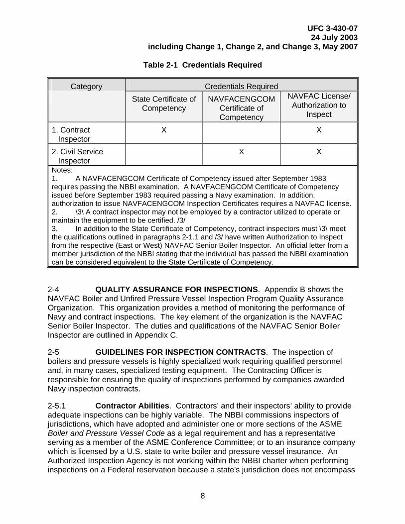
2-3 CREDENTIAL REQUIREMENTS. NAVFACENGCOM Form 9-11014/32 (3-67), Inspection Certificates, for boilers and unfired pressure vessels may only be issued by inspectors who meet one of the two category requirements in Table 2-1.
UFC 3-430-07 24 July 2003
including Change 1, Change 2, and Change 3, May 2007
8
Table 2-1 Credentials Required
Category Credentials Required State Certificate of
Competency NAVFACENGCOM
Certificate of Competency
NAVFAC License/ Authorization to
Inspect
1. Contract Inspector
X X
2. Civil Service Inspector
X X
Notes: 1. A NAVFACENGCOM Certificate of Competency issued after September 1983 requires passing the NBBI examination. A NAVFACENGCOM Certificate of Competency issued before September 1983 required passing a Navy examination. In addition, authorization to issue NAVFACENGCOM Inspection Certificates requires a NAVFAC license. 2. \3\ A contract inspector may not be employed by a contractor utilized to operate or maintain the equipment to be certified. /3/ 3. In addition to the State Certificate of Competency, contract inspectors must \3\ meet the qualifications outlined in paragraphs 2-1.1 and /3/ have written Authorization to Inspect from the respective (East or West) NAVFAC Senior Boiler Inspector. An official letter from a member jurisdiction of the NBBI stating that the individual has passed the NBBI examination can be considered equivalent to the State Certificate of Competency.
2-4 QUALITY ASSURANCE FOR INSPECTIONS. Appendix B shows the NAVFAC Boiler and Unfired Pressure Vessel Inspection Program Quality Assurance Organization. This organization provides a method of monitoring the performance of Navy and contract inspections. The key element of the organization is the NAVFAC Senior Boiler Inspector. The duties and qualifications of the NAVFAC Senior Boiler Inspector are outlined in Appendix C.
2-5 GUIDELINES FOR INSPECTION CONTRACTS. The inspection of boilers and pressure vessels is highly specialized work requiring qualified personnel and, in many cases, specialized testing equipment. The Contracting Officer is responsible for ensuring the quality of inspections performed by companies awarded Navy inspection contracts.
2-5.1 Contractor Abilities. Contractors’ and their inspectors’ ability to provide adequate inspections can be highly variable. The NBBI commissions inspectors of jurisdictions, which have adopted and administer one or more sections of the ASME Boiler and Pressure Vessel Code as a legal requirement and has a representative serving as a member of the ASME Conference Committee; or to an insurance company which is licensed by a U.S. state to write boiler and pressure vessel insurance. An Authorized Inspection Agency is not working within the NBBI charter when performing inspections on a Federal reservation because a state's jurisdiction does not encompass
UFC 3-430-07 24 July 2003
including Change 1, Change 2, and Change 3, May 2007
9
military reservations and the Government does not insure its equipment. Furthermore, Authorized Inspection Agencies usually do not qualify as small businesses.
2-5.2 \3\ Companies Other than Authorized Inspection Agencies. Quality assurance for such companies may not be structured according to a standard recognized by the NBBI or may even be non-existent. Contracting officers must ensure adequate inspections by requiring qualifications of the contractor before awarding the contract. These assurances, at a minimum, include requiring the contractor to supply inspectors meeting the credential requirements of paragraphs 2-1.1, 2-1.2 and 2-3. /3/
2-5.3 Assistance. When an activity elects to administer its own inspection contract, NAVFAC Senior Boiler Inspectors can provide assistance to the Contracting Officer by reviewing the contract requirements and determining the suitability of a company to perform inspections. The NAVFAC Senior Boiler Inspectors provide this service on a reimbursable basis. They also provide quality control by monitoring the performance of contractors and their inspectors. Upon satisfactory review, the NAVFAC Senior Boiler Inspector can issue an Authorization to Inspect to the firms qualifying inspectors for the term of the contract. The Authorization to Inspect identifies the ability of the inspector to perform the work satisfactorily and authorizes the inspector to sign the Inspection Report-Boiler or the Unfired Pressure Vessel Report and issue the Inspection Certificate, NAVFAC Form 9-11014/32 (3-67).
2-5.4 Activity Administered Contracts. When the activity’s Contracting Officer elects to administer the contracts, the Contracting Officer should require the contractors to provide enough information to determine positively that the firm has qualified inspectors and has the capability to do the required work. The scope of work for the inspection contract should include the number, function, type (such as boiler or pressure vessel), construction (such as the American Society of Mechanical Engineers’ (ASME) Boiler and Pressure Vessel Code or military specification), capacity, and pressure rating of each vessel. In addition, the contract will require that the contractor have:
• Inspectors with credentials complying with \3\ paragraphs 2-1.1, 2-2, and 2-3. /3/
• An inspection work history similar to that required for the proposed work.
UFC 3-430-07 24 July 2003
including Change 1, Change 2, and Change 3, May 2007
10
CHAPTER 3
INSPECTION AND TEST FREQUENCIES
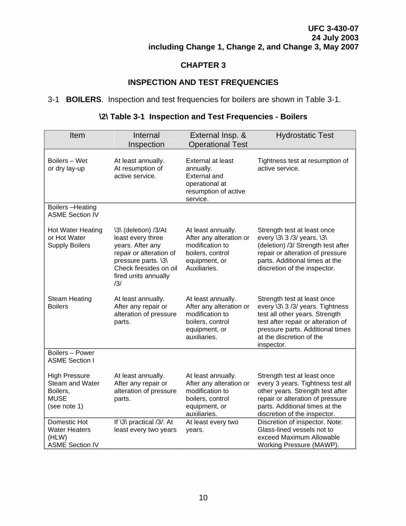
3-1 BOILERS. Inspection and test frequencies for boilers are shown in Table 3-1.
\2\ Table 3-1 Inspection and Test Frequencies - Boilers
Item Internal Inspection
External Insp. & Operational Test
Hydrostatic Test
Boilers – Wet or dry lay-up
At least annually. At resumption of active service.
External at least annually. External and operational at resumption of active service.
Tightness test at resumption of active service.
Boilers –Heating ASME Section IV Hot Water Heating or Hot Water Supply Boilers Steam Heating Boilers
\3\ (deletion) /3/At least every three years. After any repair or alteration of pressure parts. \3\ Check firesides on oil fired units annually /3/ At least annually. After any repair or alteration of pressure parts.
At least annually. After any alteration or modification to boilers, control equipment, or Auxiliaries. At least annually. After any alteration or modification to boilers, control equipment, or auxiliaries.
Strength test at least once every \3\ 3 /3/ years. \3\ (deletion) /3/ Strength test after repair or alteration of pressure parts. Additional times at the discretion of the inspector. Strength test at least once every \3\ 3 /3/ years. Tightness test all other years. Strength test after repair or alteration of pressure parts. Additional times at the discretion of the inspector.
Boilers – Power ASME Section I High Pressure Steam and Water Boilers, MUSE (see note 1)
At least annually. After any repair or alteration of pressure parts.
At least annually. After any alteration or modification to boilers, control equipment, or auxiliaries.
Strength test at least once every 3 years. Tightness test all other years. Strength test after repair or alteration of pressure parts. Additional times at the discretion of the inspector.
Domestic Hot Water Heaters (HLW) ASME Section IV
If \3\ practical /3/: At least every two years
At least every two years.
Discretion of inspector. Note: Glass-lined vessels not to exceed Maximum Allowable Working Pressure (MAWP).

UFC 3-430-07 24 July 2003
including Change 1, Change 2, and Change 3, May 2007
11
Notes: 1. Additionally, MUSE boilers and other portable boilers are to be inspected externally and internally and certified each time they are relocated from one activity to another. MUSE steam coil type boilers are exempt from annual inspections while in dry or wet lay-up.
2. All manhole and handhole gaskets must be replaced after application of the strength test unless they are of the non-compressible steel type.
/2/
3.2 UNFIRED PRESSURE VESSELS. Inspection and test frequencies for unfired pressure vessels are as shown in Tables 3-2, 3-3, or 3-4, as applicable.
\2\ Table 3-2 Inspection and Test Frequencies - Unfired Pressure Vessels (UPVs)
Item Internal Inspection External Insp. & Operational Test
Hydrostatic Test
Pressure Vessels & Heat Exchangers (15 to 250 psig MAWP)
Every 3 years or more frequently as determined by procedures in the NBBI Code for vessels subject to corrosion. After any repair or alteration of pressure parts. For LPG see Table 3-3.
Every 3 years or more frequently as determined by procedures in the NBBI Code for vessels subject to corrosion. After any repair or alteration of pressure parts. Inspection must include test and calibration of safety valves and pressure and temperature gages.
After repair or alteration of pressure parts. Additional times at the discretion of the inspector.
Pressure Vessels & Heat Exchangers (greater than 250 psig MAWP)
Every 3 years or more frequently as determined by procedures in the NBBI Code for vessels subject to corrosion. After any repair or alteration of pressure parts. For LPG see Table 3-3.
Every 3 years or more frequently as determined by procedures in the NBBI Code for vessels subject to corrosion. After any repair or alteration of pressure parts. Inspection must include test and calibration of safety valves and pressure and temperature gages.
Every 6 years of service. If inspection shows no sign of corrosion, the test may be deferred until the next inspection, but must be tested at least every 12 years. After any repair or alteration of pressure parts. Additional times at the discretion of the inspector.
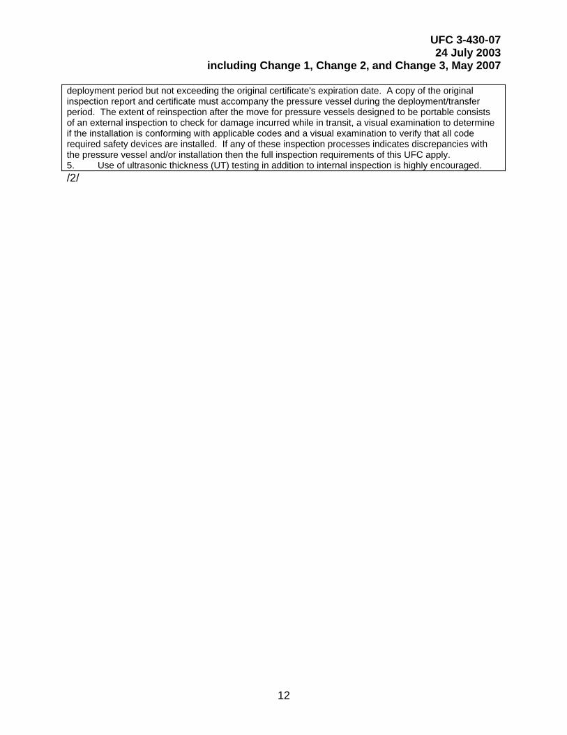
Notes: 1. Test frequencies and inspections may be increased at the discretion of the inspector or owner if the UPV is subjected, by the nature of its service, to an accumulation of deposits or thermal or mechanical stresses that could affect the integrity of the vessel. 2. A hydrostatic pressure test not to exceed 1.5 times the MAWP for BPVC ASME Section VIII Division 1 vessels and 1.25 times the MAWP for BPVC ASME Section VIII Division 2 vessels may be substituted for the internal inspection. 3. If the tube bundle of the heat exchangers is a higher pressure than the shell, both sides of the heat exchanger must be hydrostatically tested. 4. Unfired pressure vessels are to be inspected externally and re-certified anytime they are relocated or moved. It is the activity’s responsibility to inform the inspector of the move. For UPVs designed and built to be portable, reinspections are not required after a move as long as the vessel does not leave the base. The inspector will indicate the UPV is “portable” on all appropriate reports. Once a UPV designed to be portable is relocated outside the base, any certified NAVFAC boiler inspector or NAVFAC-approved contract boiler inspector may issue a certificate (9-11014/32) for the length of the
UFC 3-430-07 24 July 2003
including Change 1, Change 2, and Change 3, May 2007
12
deployment period but not exceeding the original certificate's expiration date. A copy of the original inspection report and certificate must accompany the pressure vessel during the deployment/transfer period. The extent of reinspection after the move for pressure vessels designed to be portable consists of an external inspection to check for damage incurred while in transit, a visual examination to determine if the installation is conforming with applicable codes and a visual examination to verify that all code required safety devices are installed. If any of these inspection processes indicates discrepancies with the pressure vessel and/or installation then the full inspection requirements of this UFC apply. 5. Use of ultrasonic thickness (UT) testing in addition to internal inspection is highly encouraged. /2/
UFC 3-430-07 24 July 2003
including Change 1, Change 2, and Change 3, May 2007
13
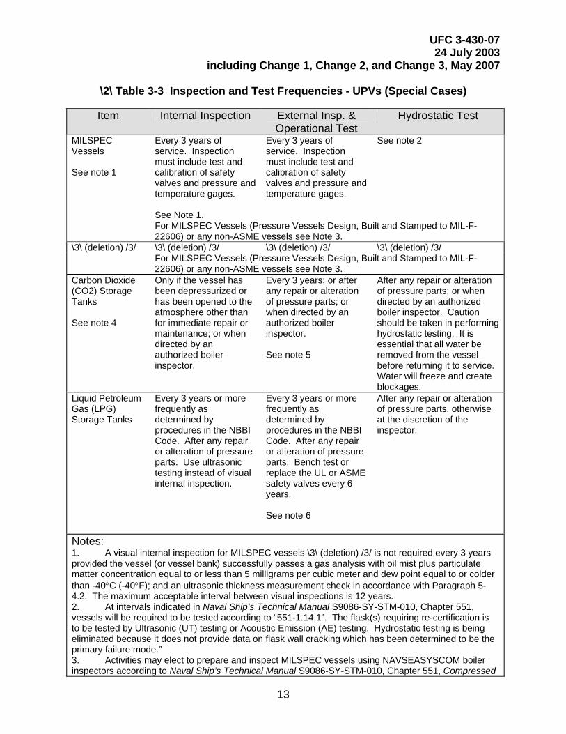
\2\ Table 3-3 Inspection and Test Frequencies - UPVs (Special Cases)
Item Internal Inspection External Insp. & Operational Test
Hydrostatic Test
MILSPEC Vessels See note 1
Every 3 years of service. Inspection must include test and calibration of safety valves and pressure and temperature gages. See Note 1.
Every 3 years of service. Inspection must include test and calibration of safety valves and pressure and temperature gages.
See note 2
For MILSPEC Vessels (Pressure Vessels Design, Built and Stamped to MIL-F-22606) or any non-ASME vessels see Note 3.
\3\ (deletion) /3/ \3\ (deletion) /3/ \3\ (deletion) /3/ \3\ (deletion) /3/ For MILSPEC Vessels (Pressure Vessels Design, Built and Stamped to MIL-F-
22606) or any non-ASME vessels see Note 3. Carbon Dioxide (CO2) Storage Tanks See note 4
Only if the vessel has been depressurized or has been opened to the atmosphere other than for immediate repair or maintenance; or when directed by an authorized boiler inspector.
Every 3 years; or after any repair or alteration of pressure parts; or when directed by an authorized boiler inspector. See note 5
After any repair or alteration of pressure parts; or when directed by an authorized boiler inspector. Caution should be taken in performing hydrostatic testing. It is essential that all water be removed from the vessel before returning it to service. Water will freeze and create blockages.
Liquid Petroleum Gas (LPG) Storage Tanks
Every 3 years or more frequently as determined by procedures in the NBBI Code. After any repair or alteration of pressure parts. Use ultrasonic testing instead of visual internal inspection.
Every 3 years or more frequently as determined by procedures in the NBBI Code. After any repair or alteration of pressure parts. Bench test or replace the UL or ASME safety valves every 6 years. See note 6
After any repair or alteration of pressure parts, otherwise at the discretion of the inspector.
Notes: 1. A visual internal inspection for MILSPEC vessels \3\ (deletion) /3/ is not required every 3 years provided the vessel (or vessel bank) successfully passes a gas analysis with oil mist plus particulate matter concentration equal to or less than 5 milligrams per cubic meter and dew point equal to or colder than -40°C (-40°F); and an ultrasonic thickness measurement check in accordance with Paragraph 5-4.2. The maximum acceptable interval between visual inspections is 12 years. 2. At intervals indicated in Naval Ship’s Technical Manual S9086-SY-STM-010, Chapter 551, vessels will be required to be tested according to “551-1.14.1”. The flask(s) requiring re-certification is to be tested by Ultrasonic (UT) testing or Acoustic Emission (AE) testing. Hydrostatic testing is being eliminated because it does not provide data on flask wall cracking which has been determined to be the primary failure mode.” 3. Activities may elect to prepare and inspect MILSPEC vessels using NAVSEASYSCOM boiler inspectors according to Naval Ship’s Technical Manual S9086-SY-STM-010, Chapter 551, Compressed
UFC 3-430-07 24 July 2003
including Change 1, Change 2, and Change 3, May 2007
14
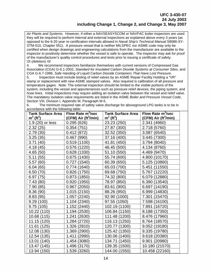
Air Plants and Systems. However, if either a NAVSEASYSCOM or NAVFAC boiler inspectors are used they will be required to perform internal and external inspections as explained above every 3 years (as opposed to the 6-20 year re-certification intervals allowed in Naval Ship’s Technical Manual S9086-SY-STM-010, Chapter 551). A pressure vessel that is neither MILSPEC nor ASME code may only be certified when design drawings and engineering calculations from the manufacturer are available to the inspector to positively determine whether the vessel is safe to operate. The inspector may ask for proof of the manufacturer’s quality control procedures and tests prior to issuing a certificate of safety. \3\ (deletion) /3/ 4. We recommend inspectors familiarize themselves with current versions of Compressed Gas Association (CGA) G-6.1-2002, Standard for Insulated Carbon Dioxide Systems at Consumer Sites, and CGA G-6.7-1996, Safe Handing of Liquid Carbon Dioxide Containers That Have Lost Pressure. 5. Inspection must include testing of relief valves by an ASME Repair Facility Holding a “VR” stamp or replacement with new ASME stamped valves. Also required is calibration of all pressure and temperature gages. Note: The external inspection should be limited to the visible portions of the system, including the vessel and appurtenances such as pressure relief devices, the piping system, and hose lines. Initial inspections may require adding an isolation valve between the vessel and relief valve. The mandatory isolation valve requirements are listed in the ASME Boiler and Pressure Vessel Code, Section VIII, Division I, Appendix M, Paragraph M-5. 6. The minimum required rate of safety valve discharge for aboveground LPG tanks is to be in accordance with the following table: Tank Surface Area m2 (ft2)
Flow Rate m3/sec (CFM) Air (ft3/min)
Tank Surface Area m2 (ft2)
Flow Rate m3/sec (CFM) Air (ft3/min)
1.9 (20) or less 0.295 (626) 23.23 (250) 2.341 (4960) 2.32 (25) 0.354 (751) 27.87 (300) 2.718 (5760) 2.79 (30) 0.412 (872) 32.52 (350) 3.087 (6540) 3.25 (35) 0.467 (990) 37.16 (400) 3.445 (7300) 3.71 (40) 0.519 (1100) 41.81 (450) 3.794 (8040) 4.18 (45) 0.576 (1220) 46.45 (500) 4.134 (8760) 4.65 (50) 0.628 (1330) 51.10 (550) 4.469 (9470) 5.11 (55) 0.675 (1430) 55.74 (600) 4.800 (10170) 5.57 (60) 0.727 (1540) 60.39 (650) 5.125 (10860) 6.04 (65) 0.774 (1640) 65.03 (700) 5.451 (11550) 6.50 (70) 0.826 (1750) 69.68 (750) 5.767 (12220) 6.97 (75) 0.873 (1850) 74.32 (800) 6.079 (12880) 7.43 (80) 0.920 (1950) 78.97 (850) 6.390 (13540) 7.90 (85) 0.967 (2050) 83.61 (900) 6.697 (14190) 8.36 (90) 1.015 (2150) 88.26 (950) 6.999 (14830) 8.83 (95) 1.057 (2240) 92.90 (1000) 7.301 (15470) 9.29 (100) 1.104 (2340) 97.55 (1050) 7.598 (16100) 9.75 (105) 1.152 (2440) 102.19 (1100) 7.891 (16720) 10.22 (110) 1.194 (2530) 106.84 (1150) 8.188 (17350) 10.68 (115) 1.241 (2630) 111.48 (1200) 8.476 (17960) 11.15 (120) 1.284 (2720) 116.13 (1250) 8.764 (18570) 11.61 (125) 1.326 (2810) 120.77 (1300) 9.052 (19180) 12.08 (130) 1.369 (2900) 125.42 (1350) 9.335 (19780) 12.54 (135) 1.411 (2990) 130.06 (1400) 9.618 (20380) 13.01 (140) 1.454 (3080) 134.71 (1450) 9.901 (20980) 13.47 (145) 1.496 (3170) 139.35 (1500) 10.180 (21570) 13.94 (150) 1.539 (3260) 144.00 (1550) 10.458 (22160)
UFC 3-430-07 24 July 2003
including Change 1, Change 2, and Change 3, May 2007
15
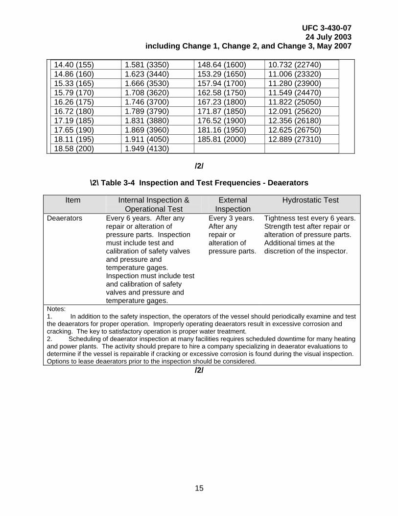
14.40 (155) 1.581 (3350) 148.64 (1600) 10.732 (22740) 14.86 (160) 1.623 (3440) 153.29 (1650) 11.006 (23320) 15.33 (165) 1.666 (3530) 157.94 (1700) 11.280 (23900) 15.79 (170) 1.708 (3620) 162.58 (1750) 11.549 (24470) 16.26 (175) 1.746 (3700) 167.23 (1800) 11.822 (25050) 16.72 (180) 1.789 (3790) 171.87 (1850) 12.091 (25620) 17.19 (185) 1.831 (3880) 176.52 (1900) 12.356 (26180) 17.65 (190) 1.869 (3960) 181.16 (1950) 12.625 (26750) 18.11 (195) 1.911 (4050) 185.81 (2000) 12.889 (27310) 18.58 (200) 1.949 (4130)
/2/
\2\ Table 3-4 Inspection and Test Frequencies - Deaerators
Item Internal Inspection & Operational Test
External Inspection
Hydrostatic Test
Deaerators Every 6 years. After any repair or alteration of pressure parts. Inspection must include test and calibration of safety valves and pressure and temperature gages. Inspection must include test and calibration of safety valves and pressure and temperature gages.
Every 3 years. After any repair or alteration of pressure parts.
Tightness test every 6 years. Strength test after repair or alteration of pressure parts. Additional times at the discretion of the inspector.
Notes: 1. In addition to the safety inspection, the operators of the vessel should periodically examine and test the deaerators for proper operation. Improperly operating deaerators result in excessive corrosion and cracking. The key to satisfactory operation is proper water treatment. 2. Scheduling of deaerator inspection at many facilities requires scheduled downtime for many heating and power plants. The activity should prepare to hire a company specializing in deaerator evaluations to determine if the vessel is repairable if cracking or excessive corrosion is found during the visual inspection. Options to lease deaerators prior to the inspection should be considered.
/2/
UFC 3-430-07 24 July 2003
including Change 1, Change 2, and Change 3, May 2007
16
CHAPTER 4
BOILER INSPECTIONS
4-1 GUIDANCE. The activity operating and maintaining the boiler provides all material and labor necessary to prepare the boilers for inspection in accordance with this UFC and the NBBI Code. The activity assists the inspector as required during the inspections. Exception to this policy occurs when the operation and maintenance of a boiler is under the cognizance of a contractor. In this case, the contractor provides material, labor, and assistance. Inspections of boilers located on Navy bases in foreign countries must comply with this UFC under the constraints of the Status Force Agreement in effect. Inspectors should not compromise safety issues, but should exercise restraint when interpreting the fine points of the ASME Code. Obtain further guidance on foreign inspections from the respective (East or West) NAVFAC Senior Boiler Inspector or the cognizant FEC serving the activity.
4-2 EXTERNAL INSPECTION OF BOILERS. Perform external inspections of boilers in accordance with \3\ Part RB-5410, /3/ External Inspections of Boilers, of the National Board Inspection Code. Test safety devices as part of the external inspection. Perform final testing of safety valves of power boilers on the boiler to which the valve will be mounted. The operational tests and observations of Chapter 7 are considered to be part of the external inspection.
4-3 INTERNAL INSPECTIONS OF BOILERS. Perform internal inspections of boilers in accordance with\3\ Part RB-5420, /3/ Internal Inspections of Boilers-Power and Heating, of the National Board Inspection Code. Boiler inspectors have the authority to order that boiler metal samples and/or ultrasonic tests be taken for their examination to ascertain the actual condition of the pressure parts.
4-4 BOILERS IN WET OR DRY LAY-UP. In addition to the external and internal inspections required above, review the lay-up procedures being used to ensure that they conform to the requirements of Appendix D.
UFC 3-430-07 24 July 2003
including Change 1, Change 2, and Change 3, May 2007
17
CHAPTER 5
UNFIRED PRESSURE VESSEL INSPECTIONS
5-1 GUIDANCE. The activity operating and maintaining the pressure vessel provides all material and labor necessary to prepare the unfired pressure vessel for inspection in accordance with this UFC and the NBBI Code. The activity assists the inspector as required during the inspections. Exception to this policy occurs when the operation and maintenance of the pressure vessel is under the cognizance of a contractor. In this case, the contractor provides material, labor, and assistance. Inspections of pressure vessels located on Navy bases in foreign countries must comply with this UFC under the constraints of the Status Force Agreement in effect. Inspectors should not compromise safety issues, but should exercise restraint when interpreting the fine points of the ASME Code. Obtain further guidance on foreign inspections from the respective (East or West) NAVFAC Senior Boiler Inspector or the cognizant FEC serving the activity.
5-2 EXTERNAL INSPECTIONS OF UNFIRED PRESSURE VESSELS. Perform external inspections of unfired pressure vessels in accordance with \3\ Part RB-6220, /3/ Inspections of Pressure Vessels, of the National Board Inspection Code.
5-3 INTERNAL INSPECTIONS OF UNFIRED PRESSURE VESSELS. Perform internal inspections of unfired pressure vessels in accordance with \3\ Part RB-6230/3/ Internal Inspections of Pressure Vessels, of the National Board Inspection Code. Inspectors have the authority to order metal samples and/or ultrasonic tests for their examination to ascertain the actual condition of the vessel.
5-4 MILITARY SPECIFICATION (MILSPEC) \3\ PRESSURE VESSELS /3/
5-4.1 Internal and External Inspections. Examine vessels in accordance with paragraphs 5-2 and 5-3. View internal surfaces using \3\ remote viewing equipment (borescope/fiberscope), /3/if necessary, supplied by the activity or by another acceptable method. Record areas of wear, corrosion, abuse, and/or damage and attach to the inspection report.
5-4.2 Ultrasonic Examination. (Only for vessels constructed per military specifications, the ultrasonic examination procedures in Naval Ship’s Technical Manual S9086-SY-STM-010, Chapter 551, 1.14.1.2 “Testing” may be used in lieu of the following.) Subject vessels to an ultrasonic thickness measurement check. The activity performs the checks while the inspector observes. Make the checks at the point of tangency between the cylinder and the end heads. Take measurements at 50.8 mm (2-inch) intervals around the circumference of the vessel. Take measurements on a line along the head from the point of tangency, across the end of the head to the far point of tangency; take measurements along a similar line at right angles to the first at the end of the head. Take lines of measurement at each end of the vessel. Arrange the lines so that the vessels low point, where water may collect and corrosion may form, is measured. Take measurements every \2\ 3 /2/ years. Ultrasonic measurement points
UFC 3-430-07 24 July 2003
including Change 1, Change 2, and Change 3, May 2007
18
for vessel configurations other than spherical or cylindrical must be approved by the inspector. The lines and points of measurement will be identical at each inspection. The activity will maintain measurement records. The vessel will not be derated nor certified if the measured thickness is less than that prescribed by the standard by which it was constructed, for example, ASME Section VIII, Division I, ASME Section VIII, Division 2, or Military Specification MIL-F-22606C, Flask Compressed Gas and End Plugs for Air, Oxygen, and Nitrogen (SHIPS).
\3\ (deletion) /3/
5-4.3 Variations. Address requests for variations in the inspection and testing procedures for MILSPEC pressure vessels to the NAVFACENGCOM Boiler Inspection Certification Board with a copy to the respective (East or West) NAVFAC Senior Boiler Inspector. \3\ (deletion) /3/ Appendix B depicts the relative position of the Boiler Inspection Certification Board in the NAVFACENGCOM boiler and pressure vessel inspection quality assurance organization.
5-5 DEAERATORS. The purpose of a deaerating heater (deaerator) is to remove non-condensable gases and dissolved oxygen from the feedwater. A properly operating deaerator will have no more than 10 ppb (parts per billion) O2 in the outlet water. Deaerators are subject to thermal cycling and corrosion. Proper operation of deaerators is extremely important because of their critical function in protecting the boiler system from corrosion. Catastrophic failure of deaerators is usually attributable to cracks forming longitudinally and transversely to the heat affected zones of the welds. Deaerators are potentially a great danger because of their location at the top of the heating or power plant. To ensure deaerators provide safe reliable service, they require periodic visual inspections of their internal and external surfaces. If visual inspection reveals cracking, then a company specializing in deaerator inspection must perform an ultrasonic examination of the entire vessel and wet fluorescent magnetic particle examinations of the heat affected zones of the welds, prior to certification, to determine if continued operation of the vessel is safe. Subject repairs to post-weld heat treatment and hydrostatic testing prior to certification.
5-6 \3\ LIQUIFIED /3/ PETROLEUM GAS (LPG) TANKS. Non-mandatory guidelines may be found in the National Board Inspection Code, Appendix H, “Recommended Guide for the Inspection of Pressure Vessels in LP Gas Service.”
5-6.1 External Inspection. Examine LPG (propane, butane, etc.) tanks in accordance with paragraph 5-2. Record areas of wear, corrosion, abuse, and/or damage and attach to the inspection report. Check capacity rating on safety relief valve nameplate for proper valve discharge.
5-6.2 Internal Inspection. These tanks contain a non-corrosive liquid, and have virtually no internal corrosion. Inspect vessels by means of an ultrasonic thickness measurement check.

UFC 3-430-07 24 July 2003
including Change 1, Change 2, and Change 3, May 2007
19
5-6.3 Hydrostatic Test. Perform hydrostatic tests after any repair or alteration of pressure parts (additional times are at the discretion of the inspector). Prior to performing a hydrostatic test, verify support structure is adequate to support the weight of the hydrostatic liquid. If a hydrostatic test is not possible, request approval for a pneumatic test from the NAVFAC Boiler Inspection Certification Board.
5-6.4 Safety Relief Valves. Fit LPG tanks with ASME Division VIII Section 1 certified, or Underwriters Laboratories UL 132 stamped, spring-loaded safety relief valves. Do not fit safety relief valves for LPG service with lifting devices. Replace, or bench test safety relief valves every 6 years of service. This will be done by a company authorized to perform such tests on either ASME or UL safety valves.
UFC 3-430-07 24 July 2003
including Change 1, Change 2, and Change 3, May 2007
20
CHAPTER 6
PRESSURE TESTS
6-1 HYDROSTATIC TESTS. Make hydrostatic tests in accordance with the paragraphs below and the National Board Inspection Code, Part \3\ RB-5430 /3/ Evidence of Leakage for boilers, and /3/ Part RB-3210 /3/ Pressure Testing for unfired pressure vessels.
6-1.1 Strength Test Pressure. Base strength tests on the maximum allowable working pressure (MAWP) of the boiler or pressure vessel as marked or as recalculated as a result of previous tests. All boilers and unfired pressure vessels covered by ASME Section I or Section VIII, Division 1 subjected to internal pressure will be tested hydrostatically at a pressure of 1-1/2 times the highest safety valve popping pressure or 1-1/2 times the MAWP, whichever is less. Unfired pressure vessels constructed by the standards of ASME Section VIII, Division 2 subjected to internal pressure will be tested hydrostatically at a pressure of 1-1/4 times the highest safety valve popping pressure or 1-1/4 times the MAWP, whichever is less. Exceptions follow:
• Vessels not capable of supporting the weight of liquids (see Chapter 10, MAWP and paragraph 6-2, Pneumatic Tests).
• Vessels not readily dried that are to be used in services where traces of the testing liquid cannot be tolerated (see Paragraph 6-2, Pneumatic Tests).
• The test pressure for enameled vessels will be at least equal to, but need not exceed, the maximum allowable working pressure marked on the vessel.
• The test pressure for glass-lined vessels will not exceed the maximum allowable working pressure.
• The test pressure for cast iron vessels will be 2 times the maximum allowable working pressure for maximum allowable working gage pressures greater than 206.84 kPa (30 psig) and 2-1/2 times the maximum allowable working pressure but not to exceed 413.69 kPa (gage pressure) (60 psig) for maximum allowable working gage pressures under 206.84 kPa (30 psig.)
• The test gage pressure for vessels and piping in high-pressure air systems (20684.27 kPa (3,000 psig and over)) will not exceed 1-1/2 times the maximum allowable working pressure of the system.
6-1.1.1 Vacuum Vessels. Single-wall vessels designed for a vacuum or partial vacuum only, and chambers of multi-chamber vessels designed for vacuum or partial vacuum only, need not be subjected to a hydrostatic test.

UFC 3-430-07 24 July 2003
including Change 1, Change 2, and Change 3, May 2007
21
6-1.1.2 Special Combination Units. Test special combination units so that each pressure chamber (vessel) receives the required hydrostatic test without pressure in the others.
6-1.1.3 Hydrostatic Tests with Fluids Other than Water. Test procedures for fluids other than water must be approved by the NAVFACENGCOM Boiler Inspection Certification Board.
6-1.2 Tightness Test Pressure. Perform the tightness test pressure at above the normal operating pressure, but not exceeding the lowest safety valve set pressure. Safety valves may be blocked or gagged for this test.
6-1.3 Precautions
• Direct connection of the boiler to the water system is prohibited, where an approved back-flow prevention device is not installed, to prevent contamination of the potable water system.
• Provide a power-driven or hand pump for application of the test pressure if the boiler feed pump will not deliver the test pressure. The test pump will be provided by the activity or its utilities contractor and operated and inspected to ensure that it is in proper working condition prior to connecting it to the boiler or the vessel.
6-1.4 Possible Deformation. If any indications of probable permanent deformation are observed, cease the test until the weak parts have been properly strengthened. If necessary repairs are not practicable, apply a new test, progressing up to 20 psi less than the pressure at which the preceding test ceased. If the test is successful, make the new maximum allowable working pressure two-thirds of the test pressure, and reset or replace the safety valves in accordance with the new maximum allowable working pressure.
6-1.5 Hold Pressure. For all boilers, UPVs and heat exchangers, pressure should not drop more than 10 percent within 15 minutes. If the pressure drop exceeds 10 percent, repair leaks and repeat the test. If the pressure drop is within 10 percent and inspection does not reveal leaks in the pressure parts, assume that the leaks are through the isolation valves, manholes, and handholes.
6-1.6 Inspection Under Pressure. Inspect all joints and connections for leaks or other defects while the vessel is under pressure. The pressure held during this inspection need not necessarily be equal to the hydrostatic test pressure, but will not be less than two-thirds of the hydrostatic pressure. Where the test pressure exceeds the MAWP of the item, the test pressure must be reduced to the MAWP for close examination by the inspector.
6-1.7 Permanent Deformation. Where permanent deformation of the unfired pressure vessel shell or heads, or of the boiler shell or drum has occurred, whether as a
UFC 3-430-07 24 July 2003
including Change 1, Change 2, and Change 3, May 2007
22
result of hydrostatic pressure tests or from normal operating pressures, make repairs only after it has first been definitely determined that such repairs are practicable and economical. After approved repairs of this nature have been completed, recalculate the maximum allowable working pressure of the vessel or boiler according to the requirements of Chapter 10. Prior to returning the vessel or boiler to service, perform a hydrostatic test, based on the recalculated maximum allowable working pressure.
6-1.8 Gaskets. Replace manhole and handhole gaskets after performing the hydrostatic strength test unless a non-compressible metal gasket is used.
6-2 PNEUMATIC TESTS. Perform a pneumatic test only in extreme cases, when a hydrostatic test is not permissible. Do not perform pneumatic tests without the written approval of the NAVFACENGCOM Boiler Inspection Certification Board. This approval can be granted by submitting a request in writing to NAVFACENGCOM via the respective NAVFAC Senior Boiler Inspector. Include the proposed pneumatic test procedures for each particular test in the request. Pneumatic test procedures for each particular test are in UG-100 for Section VIII Division 1 vessels, and in Article T-4 for Section VIII Division 2 vessels. The pneumatic test pressure will be 1.25 times the MAWP for Division 1 vessels and 1.15 times the MAWP for Division 2 vessels. A pneumatic test may be used in lieu of the hydrostatic test prescribed in paragraph 6-1 of this Chapter, with NAVFACENGCOM approval as follows:
• For vessels that are so designed and/or supported that they cannot safely be filled with water.
• For vessels not readily dried that are to be used in services where traces of the testing liquid cannot be tolerated and the parts of which have, where possible, been previously tested by hydrostatic test pressure.
6-3 PRESSURE TEST RESULTS
6-3.1 Yielding During Test. If yielding occurs, and examination shows the vessel is in satisfactory condition, establish the MAWP as 50 percent of the pressure at yielding.
6-3.2 No Yielding During Test. If yielding does not occur, increase the pressure step by step until the required test pressure has been reached. Then hold the pressure for a sufficient time to permit inspection of the vessel for leaks or signs of failure.
6-3.3 Inspection Under Pressure. If permanent deformation occurs, replace or repair the vessel. If permanent deformation occurs in a vessel not constructed to the ASME Boiler and Pressure Vessel Code, drill and discard the vessel.
UFC 3-430-07 24 July 2003
including Change 1, Change 2, and Change 3, May 2007
23
CHAPTER 7
OPERATIONAL TESTS
7-1 GUIDANCE. Following internal inspection, as part of the external inspection, bring the boiler or unfired pressure vessel up to operating pressure and temperature. Inspect, and cause to function under operating conditions, all automatically and manually operated control devices provided for controlling the operation and safety of the vessel, steam or water pressure, hot water temperature, combustion, and boiler water level. Inspect under operating conditions all associated valves and piping, pressure and temperature indicating devices, metering and recording devices, and all boiler auxiliaries. Boilers firing oil or gas without fully automatic or semiautomatic controls must have a FEC waiver to be certified. All combustion controls attached to the boiler regardless of the fuel being fired must be in good working order or the inspection certificate will be withheld. Inspections and tests of boilers may be made with the main steam or hot water distribution valves closed or open, as necessary, to fire the boiler and operate it under normal operating conditions. Testing the function of automatically or manually controlled devices and apparatus that may interfere with the distribution requirements should be done with the main steam or hot water distribution valves closed, as applicable.
7-1.1 Purpose. These additional inspections and tests allow the inspector to discover any inefficient or unsafe operation or maintenance of the vessel or of the boiler or its auxiliaries that may be evidenced under operating conditions.
7-1.2 Conditions to be Reported. Report all deficiencies requiring adjustment, repair, or replacement, and all conditions indicating excessive operating and maintenance cost. Withhold certificates until the deficiencies are corrected.
7-2 FIRING EQUIPMENT. Inspect, for any deficiency that may be evidenced under operating conditions, the operation of all firing equipment including oil burners, gas burners, fuel injectors, fuel igniters, coal stokers, and feeders, burner safety controls and other such equipment provided to introduce fuel into the boiler furnace and to ignite the fuel. All fuel leaks must be repaired before the certificate is issued.
7-3 CONTROLS. Inspect the operation of all controls directly associated with the operation and safety of the boiler for any defects preventing proper operation. These controls include such items as unloading valves, high-pressure cutout devices, high temperature cutout devices, low-pressure cut-in devices, and burner safety controls. Inspect the operation of combustion controls, steam pressure controls, water temperature controls, and feedwater controls. Make sure that the ability of the combustion control and steam pressure control to maintain proper steam pressure (or water temperature in high temperature water installations) and air-fuel ratio is demonstrated throughout the capacity range of the boiler and the load swings encountered in the operation of larger boilers. Air-fuel ratio will be checked \3\ during the inspection /3/ by the activity or the inspector by \3\ either CO2 or O2 /3/ measuring devices. CO \3\ and stack temperature /3/ will also be checked. Check fully-automatic
UFC 3-430-07 24 July 2003
including Change 1, Change 2, and Change 3, May 2007
24
boiler controls for the proper programming sequence and timing with respect to pre-purge, ignition, pilot proving, flame proving, and post-purge periods. Check the operation of flame failure and combustion air failure devices to ensure that they properly shut off the supply of fuel; this should be done by simulating a flame failure (by manually shutting off the fuel or by other means) and by observing the operation of the controls, solenoid valves, diaphragm operated valves and so forth, which are to operate during a flame failure. The installation of the boiler and controls including the fuel train and the operation of automatic burner management systems must comply with the National Fire Codes (NFC), including NFPA 85, Boiler and Combustible Systems Hazards Code; and ASME CSD-1 in effect at the time of installation of the boiler. Inspect feedwater controls, and check the ability of the controls to maintain proper water level throughout the range of capacity with load swings. Check the operation of the low-water fuel cutoff and automatic water feeding devices by draining the float bowl, lowering the boiler water level, and performing the necessary steps to cause these devices to function to ensure that they operate properly.
7-4 PIPING AND PIPING CONNECTIONS. While the boiler (or vessel) is operating, examine all steam and water pipes, including connections to the water columns and all associated piping, for leaks. If any leaks are found, determine whether they are the result of excessive strains due to expansion, contraction, water hammer, or other causes. Look for undue vibration, particularly in piping connections to the boiler and the vessel. Where excessive vibration is found, examine connections and parts for a tendency to crystallize.
7-5 DEVICES
7-5.1 Temperature Indicating Devices. Observe all temperature indicating devices for indications of excessive temperatures, particularly during and immediately following the time when high load demands are made on the boiler and the vessel.
7-5.2 Metering and Recording Devices. While the boiler is operating under normal conditions, observe the operation of all metering and recording devices. When there is evidence that any such device is not functioning properly, it must be adjusted, repaired, or replaced as necessary.
7-6 VALVES
7-6.1 Blow-Down Valves. Test the freedom of each blow-down valve and its connections by opening the valve and blowing down the boiler for a few seconds. Determine whether the valve is excessively worn or otherwise defective, and whether there is evidence of restrictions in the valve or connected piping preventing proper blow-down of the boiler.
7-6.2 Stop and Check Valves. While the boiler (or vessel) is operating, inspect the operating condition of each stop and check valve where possible. Serious defects of externally controlled stop valves may be detected by operating the valve when it is under pressure. Similarly, defects in check valves may be detected by listening to the
UFC 3-430-07 24 July 2003
including Change 1, Change 2, and Change 3, May 2007
25
operation of the valve or by observing any excessive vibration of the valve as it operates under pressure.
7-6.3 Pressure Reducing Valves. While there is pressure on the system, open and then close the by-pass valve, as safety and operating conditions permit, and observe the fluctuation of the pressure gage pointer as an aid in determining possible defects in the operation of the pressure reducing valve or the pressure gage. Look for evidence that may indicate improper condition of the relief or safety valves provided for pressure reducing valves.
7-6.4 Safety and Safety Relief Valves. Inspect the valves for evidence of leaks and proper operation. Check the popping pressure and blow-down of safety valves by allowing the pressure of the boiler to rise so that the valves lift. Inspect the valve drains and discharge to ensure that they are free from obstructions and installed according to the ASME Code. For multiple valve operations, where an accumulation test cannot be accomplished, check the freedom of the valve to lift using the lifting lever provided the pressure is within 10 percent of the valve set pressure. Similarly, check safety relief valves by using the lifting lever. Proper installation and operation is necessary prior to issuing an inspection certificate.
7-7 BOILER AUXILIARIES. While the boiler is operating under normal conditions, observe the operation of all boiler auxiliaries for any defects that may prevent the proper functioning of the boiler or which may indicate a lack of proper maintenance. Discourage the unnecessary use of multiple auxiliaries or the use of a large auxiliary during a light load period (when a smaller auxiliary could be substituted.) Steam leaks, wastage to atmosphere, and so forth, should be called to the attention of the operating personnel. Particular attention should be given to deaerator venting practice. Venting should be held to the minimum required to preclude oxygen entrainment in the feedwater. When intermittently operating condensate pumps are used, look for any tendency toward the creation of a vacuum when a pump starts. If this happens, the installation of a small continuously operating, float throttled, condensate pump (in parallel with intermittently operating pumps) will ensure a condensate flow at all times. If there are a number of intermittently operating condensate pumps, it may be possible to convert one of them (if of small enough capacity) to continuous throttled operation.
7-8 BOILER AND FEEDWATER TREATMENT. Observe the operation of equipment provided for boiler and feedwater treatment, and check the materials and procedures used for boiler and feedwater treatment to ensure adequate protection against scale and corrosion in the boiler, plant, equipment, and distribution system. The internal condition of the boilers, as evidenced from inspections required under Chapter 4, “Internal Inspection,” is the determining factor regarding the adequacy of materials, and procedures used in boiler and feedwater treatment. Withhold the certificate if an effective boiler water treatment program is not being implemented.
7-9 FUEL HANDLING PRACTICES. Check the fuel handling practices and make recommendations toward the elimination of multiple handling, heating of tanks not
UFC 3-430-07 24 July 2003
including Change 1, Change 2, and Change 3, May 2007
26
in use, and the simultaneous use of heaters in a duplex fuel oil pump and heater set where load conditions do not require this procedure. Avoid heating entire tanks. Limit heating within a tank to heating at the suction point only. With respect to residual fuel oil tanks, frequent tank changes (utilizing the full capacity of the tank, from max full to max drawdown, extending to the tank bottom) should be encouraged as a means of precluding sludge buildup.
UFC 3-430-07 24 July 2003
including Change 1, Change 2, and Change 3, May 2007
27
CHAPTER 8
REPAIRS AND ALTERATIONS
8-1 GUIDANCE. Repairs to the equipment may be necessary before certification. The activity may already be aware of necessary repairs prior to any inspections and tests. Prior to issuing a certificate, all deficiencies that cause an unsafe condition must be corrected. The repairs must be completed in accordance with the applicable code. For pressure parts, repairs must be performed in accordance with the NBBI and ASME Codes. For combustion control safeguards (burner safety controls), the equipment must be repaired to meet the requirements of the NFPA 85 or ASME CSD-1, as applicable. When deficiencies are found in the pressure parts of MIL-SPEC pressure vessels or pressure vessels of undetermined code origin, the vessels must be rendered inoperable in such a way as to prevent further use. To ensure safe operating conditions, repairs to flame safeguard equipment should only be made by the manufacturer or his authorized representative.
8-2 CONTRACTOR REPAIRS. NAVFAC /3/ (deletion) /3/ activities \3\ are allowed /3/ the option of using Navy welders qualified in accordance with the applicable Military Standards to make repairs and alterations to boilers and unfired pressure vessels, or a contractor holding a NBBI (R) stamp in accordance with Part RC of the National Board Inspection Code. For welding repairs or alterations, the contractor, or Navy organization furnishing the qualified welder, must complete a National Board Form R-1 and stamping and nameplate attachment is required.
8-2.1 \3\ NAVY WELDER QUALIFICATIONS. Either of the following procedures may be followed by a Naval Activity wishing to perform work to boilers and unfired pressure vessels:
• Any Naval Activity may apply to the National Board of Boiler and Pressure Vessel Inspectors (NBBI) and acquire a “R” Stamp in accordance with NBBI (Appendix C-R) and ASME BPVC IX.
• Any Naval Activity with access to welders currently qualified in accordance with Military Standard MIL-STD-248D and/or Military Standard MIL-STD-1595A, and meeting the requirements of ASME BPVC IX, may utilize these welders for repair work to boilers and unfired pressure vessels.
8-2.2 REPAIRS BY A NAVY WELDER. All welding must be performed in accordance with NBBI Code and applicable ASME Boiler and Pressure Vessel Codes. All weld repairs must be accompanied by a “R-1” Form, Report of Welded Repair or Alteration, as described in NBBI (Appendix C-R), and the welders’ qualification records. The records must be kept on file by the activity for each repair or alteration to a boiler or unfired pressure vessel. No alteration or welding repair shall be performed without the approval of the respective NAVFAC Senior Boiler Inspector. /3/
UFC 3-430-07 24 July 2003
including Change 1, Change 2, and Change 3, May 2007
28
8-3 SETTING SAFETY AND RELIEF VALVES. The setting of safety valves of power boilers and relief valves of UPVs within the limits of ASME Section I and VIII are adjustments. Other changes in settings, welding, or machining are repairs. Repairs and adjustments of these valves are not valid unless performed by the manufacturer or a valve repair company. Repairs by the Government are prohibited. The contractor is required to affix a National Board VR nameplate to the repaired valve. Whether the valve is repaired or adjusted; document the breaking of the seal, the setting of the valve, and resealing of the valve. Power boilers and UPVs are not certifiable unless all safety and relief valves are sealed and tagged. Bench testing the valve with no adjustments may be performed by a non-AMSE shop/Government. It is required that documentation be provided including the valve’s nameplate data, pressure at which it opened, date and time of test and the signature of the tester.
8-4 RECORDS. ANSI/NB-23, National Board Inspection Code, Appendix 5, gives the formats for the varies forms: Form R-1 Report of Welded Repair, Form R-2 Report of Alteration, Form R-3 Report of Parts Fabricated by Welding, Form R-4 Report Supplementary Sheet. If the information in these forms is acceptable to the inspector, the repairs or alterations can proceed and be inspected. Upon inspector approval of the work, the activity must make a permanent record of the repairs or alterations.
UFC 3-430-07 24 July 2003
including Change 1, Change 2, and Change 3, May 2007
29
CHAPTER 9
INSPECTION CERTIFICATES AND REPORTS
9-1 PROCEDURES FOR SUBMITTING REPORTS AND FORMS. The following hard copy reports and forms, or NAVFAC approved computer reports, are for use in the inspection and testing of boilers and unfired pressure vessels. An example of each is contained in Appendix E.
9-1.1 Inspection Reports - Boilers and Unfired Pressure Vessels. The applicable report is to be completed by the inspector to record the condition of the boiler or unfired pressure vessel, the tests performed, and the issuance of the certificate. One copy is to be retained in the activity files for a period of at least\2\ 3 /2/ years and one copy forwarded to the cognizant NAVFAC Senior Boiler Inspector \2\ ([email protected] for western half of U.S. and Pacific and [email protected] for eastern half of U.S. and Europe) /2/ within 30 days of the inspection. The inspector must promptly notify the Public Works Officer of the activity whenever inspection reports indicate safety deficiencies, pressure reductions, or unserviceability.
9-1.2 Inspection Certificate for Boilers - Unfired Pressure Vessels; NAVFAC Form 9-11014/32(3-67). A current and valid certificate, or commercial equivalent authorized by NAVFACENGCOM for contract inspection, must be posted on, or near, the equipment, \3\ by the certifying inspector /3/ under a clear protective covering. Operation of the equipment without the certificate is not authorized. The certificate will be issued under the following conditions:
• No Deficiencies: The inspector will complete and sign after the test inspection.
• Deficiencies Not Affecting Operating Safety: May be issued, but correction must be recorded on the Inspection Report.
• Deficiencies Affecting Operating Safety: Withheld until corrected and re-inspected. The activity Public Works Officer must be notified in writing listing the specific deficiencies.
• Pressure Reduction: Issued for the reduced working pressure. Oral notification, confirmed in writing, must be made by the inspector to the activity Public Works Officer.
• Unserviceable: No certificate may be issued. The inspector must notify the activity Public Works Officer in writing of the deficiencies.
• Vessels of Unknown Origin: Certificate may be issued provided it is accompanied by a plan of action with milestones to replace the vessel prior to the next inspection cycle.

UFC 3-430-07 24 July 2003
including Change 1, Change 2, and Change 3, May 2007
30
CHAPTER 10
MAXIMUM ALLOWABLE WORKING PRESSURE
10-1 GUIDANCE. The MAWP will be determined as described in the National Board Inspection Code. The following paragraphs provide further guidance on MAWP. Defects or damage discovered during the inspection must be repaired in accordance with Chapter 8. If, in the judgment of the inspector, a steam or hot water boiler or vessel is unsafe for operation at the pressure previously approved, reduce the pressure, make proper repair, or condemn the boiler or vessel.
10-2 STANDARD BOILERS. (Including expansion drums on high temperature water installations.) The maximum allowable working pressure of a boiler built in accordance with the ASME BPVC Code must not, in any case, exceed the pressure indicated by the manufacturer's identification stamped or cast upon the boiler or upon a plate secured to it. Specific requirements governing the maximum allowable working pressure on the following standard boilers must be followed.
10-2.1 Standard Watertube Boilers. The maximum allowable working gage pressure on a standard watertube boiler, the tubes of which are secured to cast iron or malleable iron headers, or which have cast iron mud drums, must not exceed 1103.16 kPa (160 psig).
10-2.2 Standard Cast Iron Steam Boilers. The maximum allowable working gage pressure for a standard cast iron steam boiler must not exceed 103.42 kPa (15 psig). Standard cast iron hot water boilers operating at temperatures not to exceed 121.1 oC (250°F) may be operated at gage pressures up to 1103.61 kPa (160 psig).
10-3 NONSTANDARD BOILERS
10-3.1 Nonstandard Riveted Boilers. The maximum allowable working pressure on the shell of a nonstandard riveted heating boiler must be determined in accordance with the Code, except that in no case can the maximum allowable working gage pressure of a steam heating boiler exceed 103.42 kPa (15 psig,) or a hot water boiler exceed 1103.16 kPa (160 psig) at a temperature not exceeding 121.1 oC (250°F).
10-3.2 Nonstandard Welded Boilers. The maximum allowable working gage pressure of a nonstandard steel or wrought iron heating boiler of welded construction must not exceed 103.42 kPa (15 psig) for steam. For other than steam service, calculate the maximum allowable working pressure in accordance with the Code.
10-3.3 Nonstandard Cast Iron Boilers. The maximum allowable working gage pressure of a nonstandard boiler composed principally of cast iron must not exceed 103.42 kPa (15 psig) for steam service, or 206.84 kPa (30 psig) for hot water service. The maximum allowable working gage pressure of a nonstandard boiler having cast iron shell or heads and steel or wrought iron tubes must not exceed 103.42 kPa (15 psig) for steam service or 206.84 kPa (30 psig) for hot water service.
UFC 3-430-07 24 July 2003
including Change 1, Change 2, and Change 3, May 2007
31
10-4 CALCULATIONS OF MAXIMUM ALLOWABLE WORKING PRESSURE. When inspection indicates that the thickness of the plate or the strength of any joint is less than that on which the current maximum allowable working pressure is based, or when it is impracticable to apply the required hydrostatic test, calculate a new maximum allowable working pressure in accordance with the rules of the Code. The following factors of safety must be used and increased by the inspector if the condition and safety of the boiler demand it:
• The lowest factor of safety permissible on existing installations is be 4.5 except for horizontal return tubular boilers having continuous longitudinal lap seams more than 3.7 m (12 feet) in length where the factor of safety is 8, and when this latter type of boiler is removed from its existing setting, it must not be reinstalled for gage pressures in excess of 103.42 kPa (15 psig.)
• Reinstalled or secondhand boilers have a minimum factor of safety of 6 when the longitudinal seams are of lap riveted construction, and a minimum factor of safety of 5 when the longitudinal seams are of butt and double strap construction.
• The maximum allowable working pressure for a vessel in operation must be computed with the appropriate formulas in the Code, using dimensions actually determined by the inspection for the thickness and twice the estimated corrosion allowance before the next inspection, and making suitable allowance for the other loadings enumerated in the Code to be considered in the design of a vessel. The maximum allowable working pressure of vessels designed and built with one or more openings, for which the closures are auxiliary equipment not part of the pressure vessels, must be determined only after due consideration of the auxiliary equipment to be used as closures. The minimum factor of safety must not be less than 4 and must be increased by the inspector if the condition and safety of the vessel demand it. The condition of the vessel and the particular service to which it is subject are the determining factors.
10-5 FACTOR OF SAFETY. The factor of safety is "built in" to the ASME Code formulas of Section I. For reference, the original formula is:
EQUATION: P = (TS x t x E) / (R x FS)
Where: P = pressure in psi TS = tensile strength, psi t = thickness, inches E = efficiency of the longitudinal seam R = inside radius, inches FS = factor of safety
UFC 3-430-07 24 July 2003
including Change 1, Change 2, and Change 3, May 2007
32
CHAPTER 11
MISHAP OR PROPERTY DAMAGE REPORTING
11-1 REPORTING REQUIREMENTS. OPNAVINST 5102.1C, Mishap Investigation and Reporting, requires that incidents which satisfy the following criteria be reported to the activity Safety Office for investigation and reporting to the Naval Safety Center:
• Damage to property involving a repair or replacement cost equal to or exceeding $10,000.
or
• Any incident involving a lost time employee mishap.
This instruction also encourages reporting of incidents where serious injury to Navy personnel was possible or if there was a "lesson to be learned.”
11-2 INFORMATION COPIES. A copy of the required report for all incidents relating to the construction, repair, operation and maintenance of the boilers and unfired pressure vessels covered by this UFC must be forwarded to the respective NAVFAC Senior Boiler Inspector for information.
UFC 3-430-07 24 July 2003
including Change 1, Change 2, and Change 3, May 2007
33
APPENDIX A
REFERENCES
GOVERNMENT PUBLICATIONS 1. Department of Defense Document Automation and Production Service Building 4/D, 700 Robbins Ave, Philadelphia, PA 19111-5094 http://astimage.daps.dla.mil/quicksearch/
MIL-F-22606, Flask Compressed Gas and End Plugs for Air, Oxygen, and Nitrogen
2. Department of the Navy SECNAV/OPNAV Directives Control Office N09B15 Washington Navy Yard, Bldg. 36 720 Kennon Street, SE Rm 203 Washington Navy Yard, DC 20374-5074 COMM: (202) 433-4934/5/6 DSN: 288-4934/5/6 FAX: (202) 433-2693 http://neds.nebt.daps.mil/usndirs.htm
CNO Letter, Inspection of Boilers, Unfired Pressure Vessels, Elevators, Dumbwaiters and Escalators OPNAVINST 5102.1C, Mishap Investigation and Reporting
3. Naval Facilities Engineering Command (NAVFACENGCOM) 1510 Gilbert St. Norfolk, VA 23511-2669 (757) 322-4200 fax (757) 322-4416 http://criteria.navfac.navy.mil/.
UFC 3-240-13FN, Industrial Water Treatment Manual NAVFAC Letter 11370/02, 1637, 18 May 1995
4. Naval Supply Systems Command 5450 Carlisle Pike, Mechanicsburg, PA. Phone: 215-697-2626 http://www.nll.navsup.navy.mil/
Navy Ship’s Technical Manual, S9086-SY-STM-010, Chapter 551, Compressed Air Plants and Systems
5. Defense Logistics Agency (DLA) Corporate Communications 8725 John J. Kingman Rd, Suite 2545 Fort Belvoir, VA 22060-6221 Phone: (703) 767-6200 http://www.dlaps.hq.dla.mil/
DLAI 4145.25/ AR 700-68/ NAVSUPINSTR 4440.128D/ AFJMAN 23-227(I)/ MCO 10330.2D, Storage and Handling of Liquefied and Gaseous Compressed Gasses and their Full and Empty Containers, 16 June 2000
UFC 3-430-07 24 July 2003
including Change 1, Change 2, and Change 3, May 2007
34
NON-GOVERNMENT PUBLICATIONS 1. ASME International Three Park Avenue New York, NY 10016-5990 800-843-2763 (U.S/Canada) 95-800-843-2763 (Mexico) 973-882-1167 (outside North America) Email: [email protected] http://www.asme.org/
Boiler and Pressure Vessel Code ASME CSD-1, Control and Safety Devices for Automatically Fired Boilers
2. National Board of Boiler and Pressure Vessel Inspectors 1055 Crupper Avenue, Columbus OH 43229 (614)888-8320 http://www.nationalboard.net
ANSI/NB-23, National Boiler Inspecter Code
3. National Fire Protection Association (NFPA) 1 Batterymarch Park Quincy, MA 02269-9101 (617) 770-3000 Fax: (617) 770-0700 http://www.nfpa.org
National Fire Codes NFPA 85, Boiler and Combustible Systems Hazards Code - 2001
4. Compressed Gas Association (CGA) 4221 Walney Road, 5th Floor Chantilly VA 20151-2923 Phone: 703-788-2700 Fax: 703-961-1831 Email: [email protected] http://www.cganet.com/
G-6.1-2002, Standard for Insulated Carbon Dioxide Systems at Consumer Sites G-6.7-1996, Safe Handling of Liquid Carbon Dioxide Containers That Have Lost Pressure
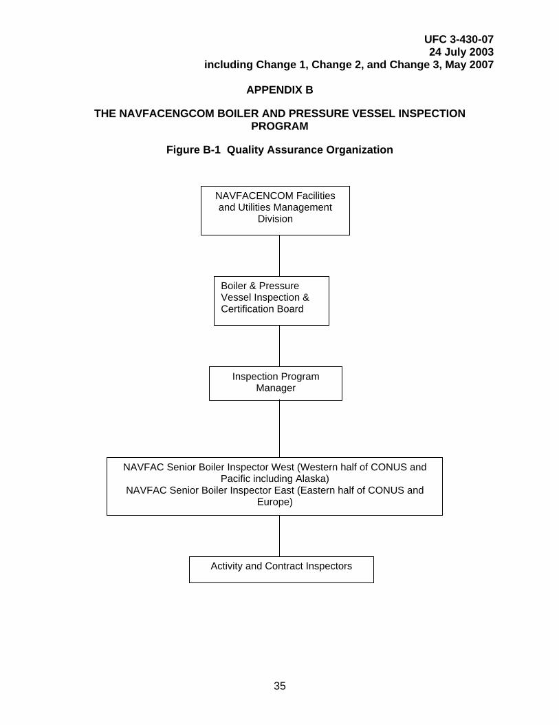
UFC 3-430-07 24 July 2003
including Change 1, Change 2, and Change 3, May 2007
35
APPENDIX B
THE NAVFACENGCOM BOILER AND PRESSURE VESSEL INSPECTION PROGRAM
Figure B-1 Quality Assurance Organization
NAVFACENCOM Facilities and Utilities Management
Division
Boiler & Pressure Vessel Inspection & Certification Board
Inspection Program Manager
NAVFAC Senior Boiler Inspector West (Western half of CONUS and Pacific including Alaska)
NAVFAC Senior Boiler Inspector East (Eastern half of CONUS and Europe)
Activity and Contract Inspectors
UFC 3-430-07 24 July 2003
including Change 1, Change 2, and Change 3, May 2007
36
APPENDIX C
DUTIES AND QUALIFICATIONS OF THE SENIOR BOILER INSPECTORS
The duties of the Senior Boiler Inspectors are:
1. Monitor status of inspections at all activities. This will include administering NAVFAC boiler and UPV inspection reporting software.
2. Perform random performance checks of Navy and contractor inspections.
3. \3\ At their discretion, accompany contractors and/or Navy inspectors on inspections. /3/
4. Provide consultation services, technical support, and guidance to Navy and contract inspectors.
5. Review and maintain all inspection reports. Notify Commanding Officers and Public Works Officers of boiler and UPV that are delinquent by 3 or more months.
6. Conduct NAVFAC Boiler Inspector workshops every 2 years.
7. Coordinate inspections of new boilers and pressure vessels as requested by NAVFAC Resident Officer In Charge of Construction (ROICCs).
8. Propose changes to \1\ UFC 3-430-07 /1/.
9. Attend Senior Boiler Inspector workshops.
10. Ensure activities correct safety violations.
11. Enlist NAVFAC support for correction of violations when necessary.
12. Void boiler and unfired pressure vessel inspection certificates and inspector licenses when appropriate.
13. License activity and contract inspections (new and renewals).
The qualifications of the NAVFAC Senior Boiler Inspectors are:
1. Posses a valid NAVFAC Senior Boiler Inspector Certificate of Competency.
2. Possess a valid NAVFAC Boiler Inspector's License.
3. Have at least 5 years experience in the inspection of high-pressure power boilers.
UFC 3-430-07 24 July 2003
including Change 1, Change 2, and Change 3, May 2007
37
APPENDIX D
PROCEDURES FOR LAY-UP OF BOILERS
D-1 Guidance. When a boiler is taken out of service, the boiler should be cooled until the water is below the atmospheric boiling point, but not below 82.2 ºC (180°F); the boiler should be emptied and flushed out. An inspection should be made to determine what repair work is necessary and what mechanical and chemical cleaning should be done. A decision should then be made on whether to employ dry storage or wet storage. Since freshly cleaned metal surfaces are much more vulnerable to corrosion than surfaces that have operational oxides on them, prefer delay of chemical cleaning until the boiler is ready to be returned to service.
D-2 Dry Storage. This procedure is preferred for boilers out of service for extended periods of time or in locations where freezing temperatures may be expected during standby.
D-2.1 The boiler should be thoroughly dried, since any moisture left on the metal surface would cause corrosion to occur on long standby. After drying, precautions should be taken to preclude entry of moisture in any form from steam lines, feed lines, or air.
D-2.2 Moisture absorbing material, such as quicklime at the rate of 0.9 kg (2 lbs,) or silica gel at the rate of 2.3 kg (5 lbs), for 0.85 cu. meters (30 cu. feet) of boiler volume, is placed on trays inside the drums to absorb moisture from the air. The manholes should then be closed and all connections on the boiler should be tightly blanked. The effectiveness of materials for such purposes and need for their renewal may be determined through regular internal boiler inspections.
D-2.3 Alternatively, air dried externally to the boiler may be circulated through it. The distribution should be carefully checked to be sure the air flows over all areas.
D-2.4 It is usually desirable in the case of large utility boilers (particularly the once-through type) to simply drain the boiler while feeding nitrogen to the boiler vents and maintaining a 34.47 kPa (5-psig) nitrogen gage pressure during the storage period.
D-3 Wet Storage. A wet procedure may be used for a boiler to be placed in a standby condition. Wet storage is particularly useful if the standby boiler may be required for service at short notice or it is impractical to employ a dry storage procedure. The method is not generally employed for reheaters or for boilers that may be subject to freezing temperatures. Several procedures have been employed.
D-3.1 The empty boiler should be closed and filled to the top with water conditioned chemically to minimize corrosion during standby. Water pressure greater than atmospheric should be maintained within the boiler during the storage period. A head tank may be connected to the highest vent of the boiler to maintain a pressure above atmospheric.
UFC 3-430-07 24 July 2003
including Change 1, Change 2, and Change 3, May 2007
38
D-3.2 For a short storage period, condensate or feedwater containing approximately 100 to 200 ppm of sodium sulfite may be used. If the superheater is drainable, it can also be filled with the same treated water by overflow from the boiler.
D-3.3 If the superheater is not drainable, refer to the plant operating manual or request assistance from your respective FEC.
D-4 Alternative Wet Lay-Up Methods. The boiler may be stored with water at a normal operating level in the drum and nitrogen maintained at greater than atmospheric pressure in all vapor spaces. To prevent in-leakage of air, it is necessary to supply nitrogen at the vents before the boiler pressure falls to zero as the boiler is coming off line. If boiler pressure falls to zero, the boiler should be fired to reestablish pressure and the superheater and reheater thoroughly vented to remove air before nitrogen is admitted. All partly filled steam drums and superheater and reheater headers should be connected in parallel to the nitrogen supply. If nitrogen is supplied only to the steam drum, nitrogen pressure should be greater than the hydrostatic head of the longest vertical column of condensate that could be produced in the superheater. Rather than maintain the water in the boiler at normal operating level with a nitrogen cap, it is sometimes preferable to drain the boiler completely, applying nitrogen continuously during the draining operation and maintaining a pressure of nitrogen greater than atmospheric throughout the draining and subsequent storage.
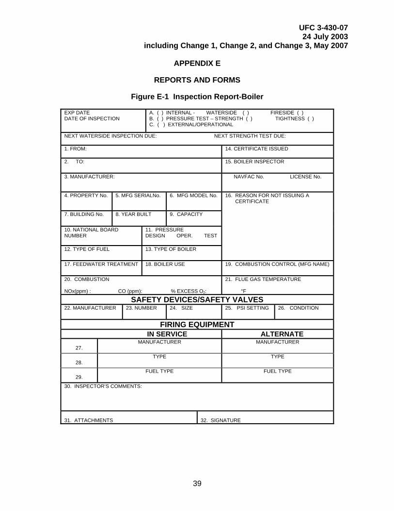
UFC 3-430-07 24 July 2003
including Change 1, Change 2, and Change 3, May 2007
39
APPENDIX E
REPORTS AND FORMS
Figure E-1 Inspection Report-Boiler
EXP DATE DATE OF INSPECTION
A. ( ) INTERNAL - WATERSIDE ( ) FIRESIDE ( ) B. ( ) PRESSURE TEST – STRENGTH ( ) TIGHTNESS ( ) C. ( ) EXTERNAL/OPERATIONAL
NEXT WATERSIDE INSPECTION DUE: NEXT STRENGTH TEST DUE: 1. FROM:
14. CERTIFICATE ISSUED
2. TO: 15. BOILER INSPECTOR
3. MANUFACTURER:
NAVFAC No. LICENSE No.
4. PROPERTY No. 5. MFG SERIALNo. 6. MFG MODEL No.
16. REASON FOR NOT ISSUING A CERTIFICATE
7. BUILDING No. 8. YEAR BUILT 9. CAPACITY
10. NATIONAL BOARD NUMBER
11. PRESSURE DESIGN OPER. TEST
12. TYPE OF FUEL
13. TYPE OF BOILER
17. FEEDWATER TREATMENT
18. BOILER USE
19. COMBUSTION CONTROL (MFG NAME)
20. COMBUSTION NOx(ppm) : CO (ppm): % EXCESS O2:
21. FLUE GAS TEMPERATURE °F
SAFETY DEVICES/SAFETY VALVES 22. MANUFACTURER
23. NUMBER
24. SIZE
25. PSI SETTING
26. CONDITION
FIRING EQUIPMENT IN SERVICE ALTERNATE
27.
MANUFACTURER
MANUFACTURER
28.
TYPE
TYPE
29.
FUEL TYPE
FUEL TYPE
30. INSPECTOR’S COMMENTS:
31. ATTACHMENTS
32. SIGNATURE
UFC 3-430-07 24 July 2003
including Change 1, Change 2, and Change 3, May 2007
40
Instructions for Completing
Inspection Report - Boiler
Use a separate form for each boiler. The following subparagraph numbers refer to number blocks on the report.
1. From: Enter the name of inspection department performing the inspection.
2. To: Enter the title of the activity for which the inspection is being made.
3. Manufacturer: Enter the name of the manufacturer.
4. Property No.: Enter the identification number as indicated by the activity.
5. Manufacturer's Serial No.: Enter the serial number as indicated by the manufacturer.
6. Manufacturer's Model No.: Enter the model number as indicated by the manufacturer.
7. Building No.: Enter the building or structure number in which the boiler is located.
8. Year Built: Indicate the calendar year in which the boiler was constructed.
9. Capacity: Show capacity in millions of BTUs per hour. One (1) pound per hour of steam is approximately equal to 292.8 W (1,000 BTUs.) One (1) boiler horsepower is approximately equal to 9809.1 W (33,500 BTUs) per hour.
10. National Board Number: Enter the boiler National Board Number
11. Pressure: Enter the design, operating, and test pressures (psig).
12. Fuel: Enter appropriate fuel, e.g., natural gas, No. 2 to 6 fuel oil, propane, coal, solid waste, etc.
13. Type: Enter type of boiler, e.g., cast iron, watertube, firetube.
14. Certificate Issued: Enter yes or no.
15. Boiler Inspector: Signature of authorized inspector. Indicate the Navy Certificate of Competency number and/or NAVFAC (formerly called EFD) License to Inspect. Contract inspectors are to indicate their NAVFAC Authorization to Inspect.
16. Reason for Not Issuing Certificate: Enter the reason for not issuing the certificate.
17. Boiler Feedwater Treatment: Enter if treatment is Satisfactory or Unsatisfactory.
UFC 3-430-07 24 July 2003
including Change 1, Change 2, and Change 3, May 2007
41
18. Boiler Use: Enter the primary purpose of the boiler (space heating, power generation, cogeneration, process load, etc.).
19. Combustion Control: Enter the combustion control manufacturer and indicate if automatic or semi-automatic.
20. Combustion: Enter appropriate percentages.
21. Flue Gas Temperature: Enter, in degrees Fahrenheit, the temperature of the flue gas immediately after the boiler.
22. Manufacturer: Enter the name of the safety valve manufacturer.
23. Number: Enter the number of the safety valves on the unit.
24. Size: Enter the size of the safety valves.
25. PSI Settings: Enter the lifting pressure of the safety valves.
26. Condition: Enter the condition of the safety valve or valves as Satisfactory or Unsatisfactory.
27. Manufacturer: Enter the name of the primary fuel firing equipment manufacturer in column 1 and the alternate fuel in column 2.
28. Type: Enter the type of firing equipment (including the alternate).
29. Fuel Grade: Enter the primary and secondary fuel types, grade, e.g., natural gas, No. 2 fuel oil, No. 6 fuel oil, etc.
30. Inspector's Comments: Enter any comment regarding boiler discrepancies, etc.
31. Attachments: Enter yes or no.
32. Signature: Signature of Commanding Officer or other person authorized to forward the report.
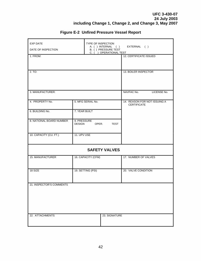
UFC 3-430-07 24 July 2003
including Change 1, Change 2, and Change 3, May 2007
42
Figure E-2 Unfired Pressure Vessel Report
EXP DATE DATE OF INSPECTION
TYPE OF INSPECTION A. ( ) INTERNAL ( ) EXTERNAL ( ) B. ( ) PRESSURE TEST C. ( ) OPERATIONAL TEST
1. FROM:
12. CERTIFICATE ISSUED
2. TO:
13. BOILER INSPECTOR
3. MANUFACTURER:
NAVFAC No. LICENSE No.
4. PROPERTY No. 5. MFG SERIAL No.
14. REASON FOR NOT ISSUING A CERTIFICATE
6. BUILDING No.
7. YEAR BUILT
8. NATIONAL BOARD NUMBER
9. PRESSURE DESIGN OPER. TEST
10. CAPACITY (CU. FT.)
11. UPV USE
SAFETY VALVES
15. MANUFACTURER
16. CAPACITY (CFM)
17. NUMBER OF VALVES
18 SIZE
19. SETTING (PSI)
20. VALVE CONDITION
21. INSPECTOR’S COMMENTS
22. ATTACHMENTS 23. SIGNATURE
UFC 3-430-07 24 July 2003
including Change 1, Change 2, and Change 3, May 2007
43
Instructions for Completing
Unfired Pressure Vessel (UPV) Report
Use a separate form for each UPV. The following subparagraph numbers refer to number blocks on the report.
1. Form: Enter the name of inspection department performing the inspection.
2. To: Enter the title of the activity for which the inspection is being made.
3. Manufacturer: Enter the name of the manufacturer.
4. Property No.: Enter the identification number as indicated by the activity.
5. Manufacturer's Serial No.: Enter the serial number as indicated by the manufacturer.
6. Building No.: Enter the building or structure number in which the UPV is located.
7. Year Built: Indicate the calendar year in which the UPV was constructed.
8. National Board Number: Enter the vessel National Board Number
9. Pressure: Enter the design, operating, and test pressures (psig).
10. Capacity: Enter capacity in cubic feet.
11. UPV Use: Enter the primary purpose of the UPV (shop air, control air, etc.).
12. Certificate Issued: Enter yes or no.
13. Boiler Inspector: Signature of authorized inspector. Indicate the Navy Certificate of Competency number and/or NAVFAC (formerly EFD) License to Inspect. Contract inspectors are to indicate their NAVFAC Authorization to Inspect.
14. Reason for Not Issuing Certificate: Enter the reason for not issuing the certificate.
15. Manufacturer: Enter the name of the safety valve manufacturer.
16. Safety Valves Capacity (CFM): Enter capacity of valves.
17. Number of Valves: Enter the number of safety valves.
18. Size of Safety Valves: Enter the size of the safety valves in inches.
19. Setting (PSI): Enter safety valve setting.
UFC 3-430-07 24 July 2003
including Change 1, Change 2, and Change 3, May 2007
44
20. Valve Condition: Enter Satisfactory or Unsatisfactory.
21. Inspector's Comments: Enter any comment regarding UPV discrepancies, etc.
22. Attachments: Enter yes or no.
23. Signature: Signature of Commanding Officer or other person authorized to forward the report.
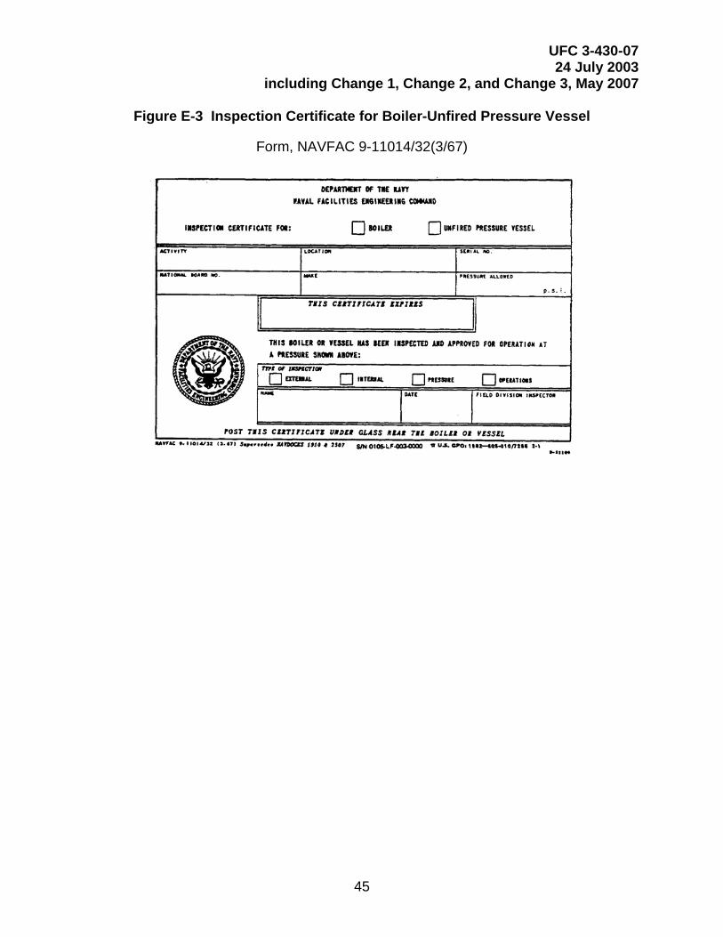
UFC 3-430-07 24 July 2003
including Change 1, Change 2, and Change 3, May 2007
45
Figure E-3 Inspection Certificate for Boiler-Unfired Pressure Vessel
Form, NAVFAC 9-11014/32(3/67)
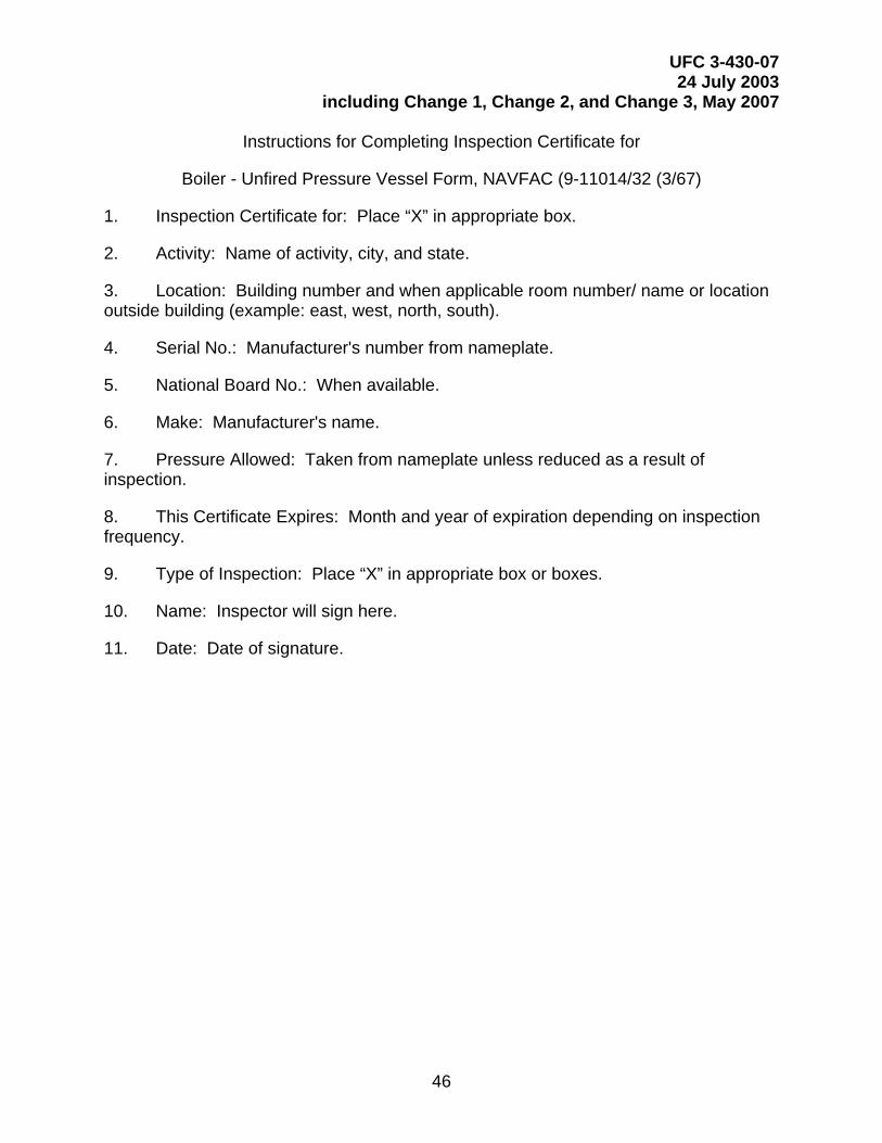
UFC 3-430-07 24 July 2003
including Change 1, Change 2, and Change 3, May 2007
46
Instructions for Completing Inspection Certificate for
Boiler - Unfired Pressure Vessel Form, NAVFAC (9-11014/32 (3/67)
1. Inspection Certificate for: Place “X” in appropriate box.
2. Activity: Name of activity, city, and state.
3. Location: Building number and when applicable room number/ name or location outside building (example: east, west, north, south).
4. Serial No.: Manufacturer's number from nameplate.
5. National Board No.: When available.
6. Make: Manufacturer's name.
7. Pressure Allowed: Taken from nameplate unless reduced as a result of inspection.
8. This Certificate Expires: Month and year of expiration depending on inspection frequency.
9. Type of Inspection: Place “X” in appropriate box or boxes.
10. Name: Inspector will sign here.
11. Date: Date of signature.
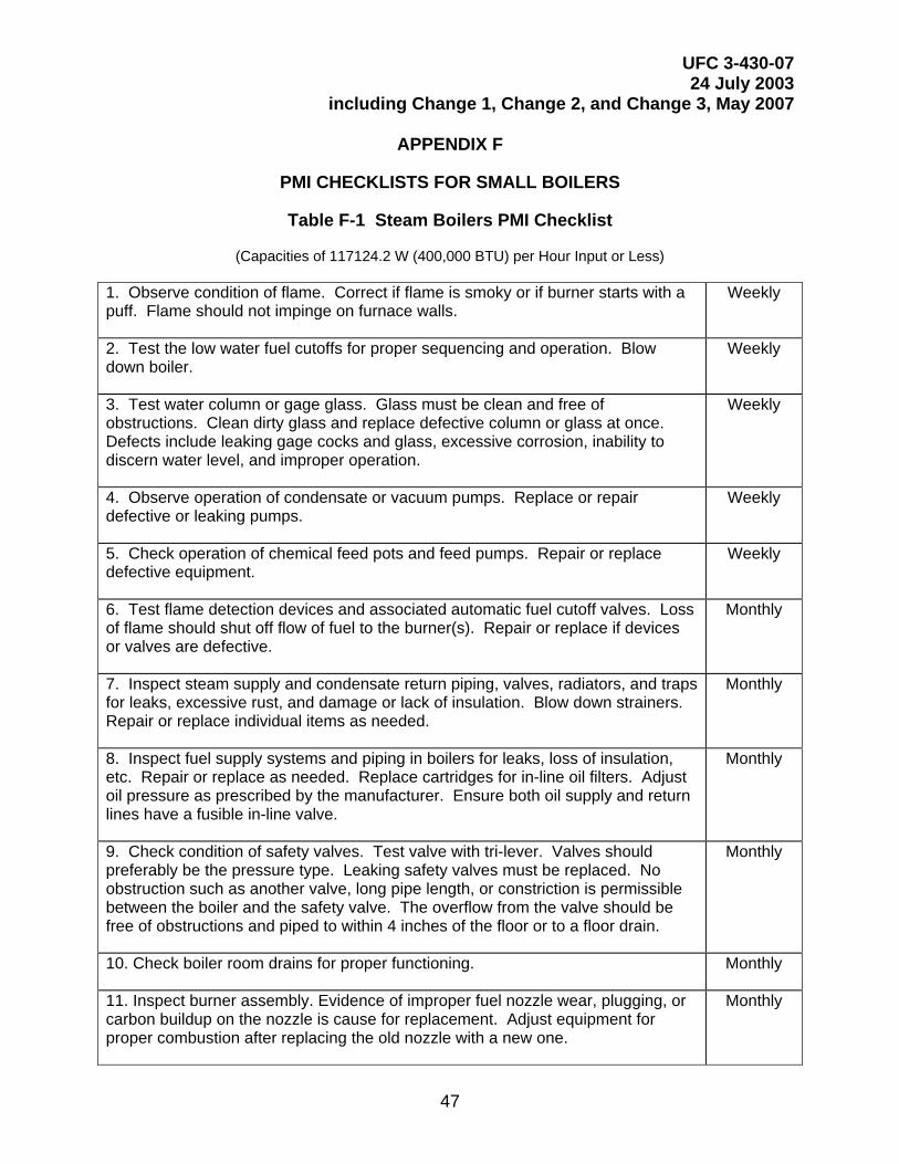
UFC 3-430-07 24 July 2003
including Change 1, Change 2, and Change 3, May 2007
47
APPENDIX F
PMI CHECKLISTS FOR SMALL BOILERS
Table F-1 Steam Boilers PMI Checklist
(Capacities of 117124.2 W (400,000 BTU) per Hour Input or Less)
1. Observe condition of flame. Correct if flame is smoky or if burner starts with a puff. Flame should not impinge on furnace walls.
Weekly
2. Test the low water fuel cutoffs for proper sequencing and operation. Blow down boiler.
Weekly
3. Test water column or gage glass. Glass must be clean and free of obstructions. Clean dirty glass and replace defective column or glass at once. Defects include leaking gage cocks and glass, excessive corrosion, inability to discern water level, and improper operation.
Weekly
4. Observe operation of condensate or vacuum pumps. Replace or repair defective or leaking pumps.
Weekly
5. Check operation of chemical feed pots and feed pumps. Repair or replace defective equipment.
Weekly
6. Test flame detection devices and associated automatic fuel cutoff valves. Loss of flame should shut off flow of fuel to the burner(s). Repair or replace if devices or valves are defective.
Monthly
7. Inspect steam supply and condensate return piping, valves, radiators, and traps for leaks, excessive rust, and damage or lack of insulation. Blow down strainers. Repair or replace individual items as needed.
Monthly
8. Inspect fuel supply systems and piping in boilers for leaks, loss of insulation, etc. Repair or replace as needed. Replace cartridges for in-line oil filters. Adjust oil pressure as prescribed by the manufacturer. Ensure both oil supply and return lines have a fusible in-line valve.
Monthly
9. Check condition of safety valves. Test valve with tri-lever. Valves should preferably be the pressure type. Leaking safety valves must be replaced. No obstruction such as another valve, long pipe length, or constriction is permissible between the boiler and the safety valve. The overflow from the valve should be free of obstructions and piped to within 4 inches of the floor or to a floor drain.
Monthly
10. Check boiler room drains for proper functioning. Monthly
11. Inspect burner assembly. Evidence of improper fuel nozzle wear, plugging, or carbon buildup on the nozzle is cause for replacement. Adjust equipment for proper combustion after replacing the old nozzle with a new one.
Monthly
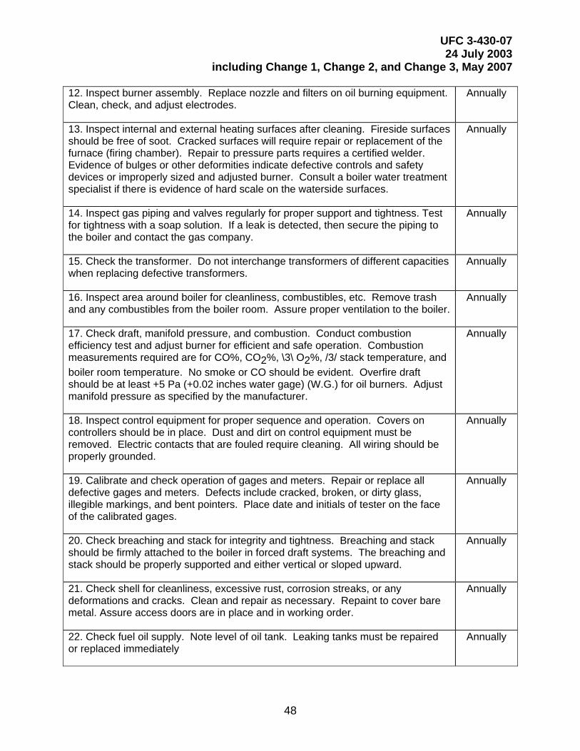
UFC 3-430-07 24 July 2003
including Change 1, Change 2, and Change 3, May 2007
48
12. Inspect burner assembly. Replace nozzle and filters on oil burning equipment. Clean, check, and adjust electrodes.
Annually
13. Inspect internal and external heating surfaces after cleaning. Fireside surfaces should be free of soot. Cracked surfaces will require repair or replacement of the furnace (firing chamber). Repair to pressure parts requires a certified welder. Evidence of bulges or other deformities indicate defective controls and safety devices or improperly sized and adjusted burner. Consult a boiler water treatment specialist if there is evidence of hard scale on the waterside surfaces.
Annually
14. Inspect gas piping and valves regularly for proper support and tightness. Test for tightness with a soap solution. If a leak is detected, then secure the piping to the boiler and contact the gas company.
Annually
15. Check the transformer. Do not interchange transformers of different capacities when replacing defective transformers.
Annually
16. Inspect area around boiler for cleanliness, combustibles, etc. Remove trash and any combustibles from the boiler room. Assure proper ventilation to the boiler.
Annually
17. Check draft, manifold pressure, and combustion. Conduct combustion efficiency test and adjust burner for efficient and safe operation. Combustion measurements required are for CO%, CO2%, \3\ O2%, /3/ stack temperature, and boiler room temperature. No smoke or CO should be evident. Overfire draft should be at least +5 Pa (+0.02 inches water gage) (W.G.) for oil burners. Adjust manifold pressure as specified by the manufacturer.
Annually
18. Inspect control equipment for proper sequence and operation. Covers on controllers should be in place. Dust and dirt on control equipment must be removed. Electric contacts that are fouled require cleaning. All wiring should be properly grounded.
Annually
19. Calibrate and check operation of gages and meters. Repair or replace all defective gages and meters. Defects include cracked, broken, or dirty glass, illegible markings, and bent pointers. Place date and initials of tester on the face of the calibrated gages.
Annually
20. Check breaching and stack for integrity and tightness. Breaching and stack should be firmly attached to the boiler in forced draft systems. The breaching and stack should be properly supported and either vertical or sloped upward.
Annually
21. Check shell for cleanliness, excessive rust, corrosion streaks, or any deformations and cracks. Clean and repair as necessary. Repaint to cover bare metal. Assure access doors are in place and in working order.
Annually
22. Check fuel oil supply. Note level of oil tank. Leaking tanks must be repaired or replaced immediately
Annually
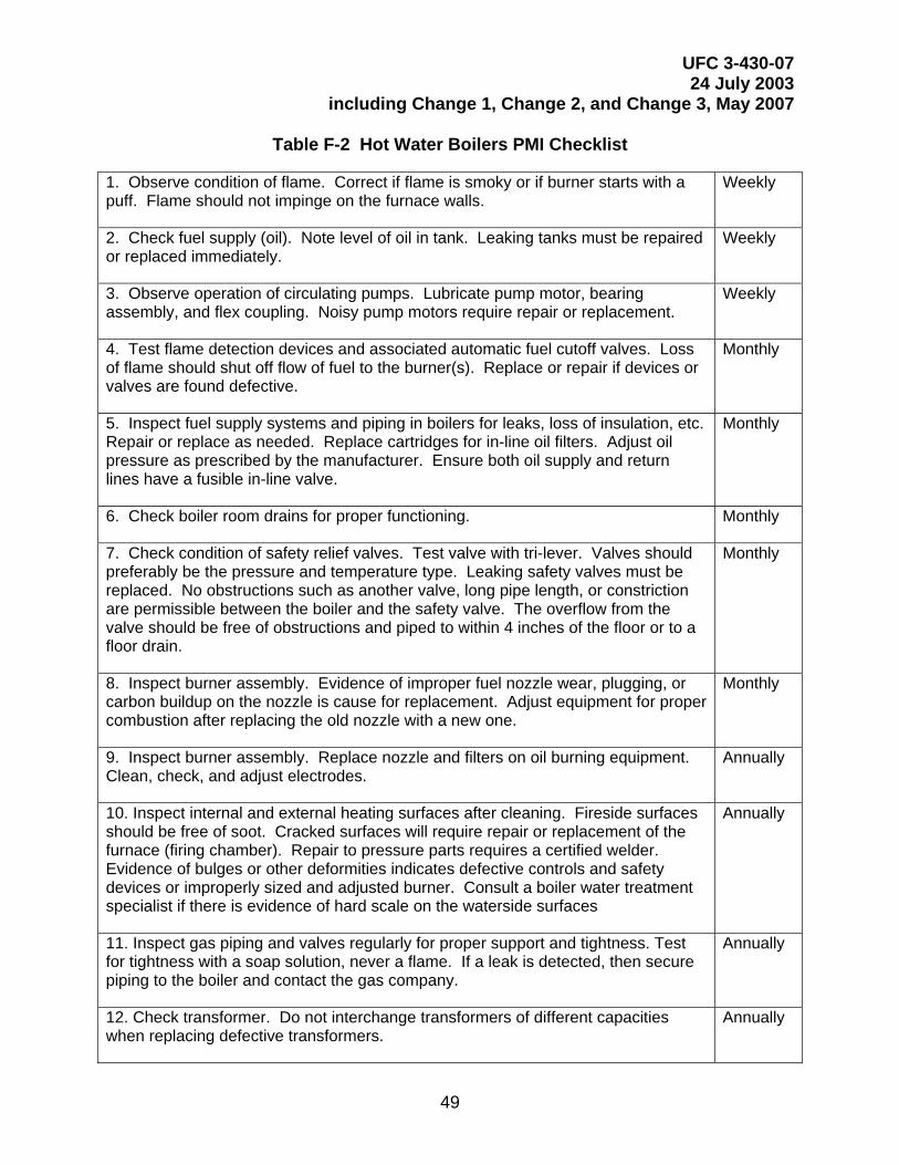
UFC 3-430-07 24 July 2003
including Change 1, Change 2, and Change 3, May 2007
49
Table F-2 Hot Water Boilers PMI Checklist
1. Observe condition of flame. Correct if flame is smoky or if burner starts with a puff. Flame should not impinge on the furnace walls.
Weekly
2. Check fuel supply (oil). Note level of oil in tank. Leaking tanks must be repaired or replaced immediately.
Weekly
3. Observe operation of circulating pumps. Lubricate pump motor, bearing assembly, and flex coupling. Noisy pump motors require repair or replacement.
Weekly
4. Test flame detection devices and associated automatic fuel cutoff valves. Loss of flame should shut off flow of fuel to the burner(s). Replace or repair if devices or valves are found defective.
Monthly
5. Inspect fuel supply systems and piping in boilers for leaks, loss of insulation, etc. Repair or replace as needed. Replace cartridges for in-line oil filters. Adjust oil pressure as prescribed by the manufacturer. Ensure both oil supply and return lines have a fusible in-line valve.
Monthly
6. Check boiler room drains for proper functioning. Monthly
7. Check condition of safety relief valves. Test valve with tri-lever. Valves should preferably be the pressure and temperature type. Leaking safety valves must be replaced. No obstructions such as another valve, long pipe length, or constriction are permissible between the boiler and the safety valve. The overflow from the valve should be free of obstructions and piped to within 4 inches of the floor or to a floor drain.
Monthly
8. Inspect burner assembly. Evidence of improper fuel nozzle wear, plugging, or carbon buildup on the nozzle is cause for replacement. Adjust equipment for proper combustion after replacing the old nozzle with a new one.
Monthly
9. Inspect burner assembly. Replace nozzle and filters on oil burning equipment. Clean, check, and adjust electrodes.
Annually
10. Inspect internal and external heating surfaces after cleaning. Fireside surfaces should be free of soot. Cracked surfaces will require repair or replacement of the furnace (firing chamber). Repair to pressure parts requires a certified welder. Evidence of bulges or other deformities indicates defective controls and safety devices or improperly sized and adjusted burner. Consult a boiler water treatment specialist if there is evidence of hard scale on the waterside surfaces
Annually
11. Inspect gas piping and valves regularly for proper support and tightness. Test for tightness with a soap solution, never a flame. If a leak is detected, then secure piping to the boiler and contact the gas company.
Annually
12. Check transformer. Do not interchange transformers of different capacities when replacing defective transformers.
Annually
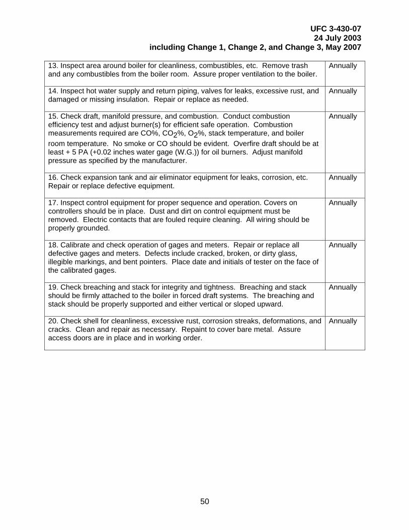
UFC 3-430-07 24 July 2003
including Change 1, Change 2, and Change 3, May 2007
50
13. Inspect area around boiler for cleanliness, combustibles, etc. Remove trash and any combustibles from the boiler room. Assure proper ventilation to the boiler.
Annually
14. Inspect hot water supply and return piping, valves for leaks, excessive rust, and damaged or missing insulation. Repair or replace as needed.
Annually
15. Check draft, manifold pressure, and combustion. Conduct combustion efficiency test and adjust burner(s) for efficient safe operation. Combustion measurements required are CO%, CO2%, O2%, stack temperature, and boiler room temperature. No smoke or CO should be evident. Overfire draft should be at least + 5 PA (+0.02 inches water gage (W.G.)) for oil burners. Adjust manifold pressure as specified by the manufacturer.
Annually
16. Check expansion tank and air eliminator equipment for leaks, corrosion, etc. Repair or replace defective equipment.
Annually
17. Inspect control equipment for proper sequence and operation. Covers on controllers should be in place. Dust and dirt on control equipment must be removed. Electric contacts that are fouled require cleaning. All wiring should be properly grounded.
Annually
18. Calibrate and check operation of gages and meters. Repair or replace all defective gages and meters. Defects include cracked, broken, or dirty glass, illegible markings, and bent pointers. Place date and initials of tester on the face of the calibrated gages.
Annually
19. Check breaching and stack for integrity and tightness. Breaching and stack should be firmly attached to the boiler in forced draft systems. The breaching and stack should be properly supported and either vertical or sloped upward.
Annually
20. Check shell for cleanliness, excessive rust, corrosion streaks, deformations, and cracks. Clean and repair as necessary. Repaint to cover bare metal. Assure access doors are in place and in working order.
Annually
UFC 3-430-07 24 July 2003
including Change 1, Change 2, and Change 3, May 2007
51
APPENDIX G
WHAT TO EXPECT WHEN THE BOILER INSPECTOR CALLS
The following article is reprinted unabridged with the permission of HEATING, PIPING, and AIR CONDITIONING. The author is John G. Gillissie, a field representative of the National Board of Boiler and Pressure Vessel Inspectors.
The article is provided as a general guide for use by activities when preparing boilers for inspection. The text of this UFC contains further guidance.
WHAT TO EXPECT WHEN THE BOILER INSPECTOR CALLS
Here's what you can and should do to help him to ensure the safety and integrity of your boiler plant.
Boilers are so common and essential that their safe and effective operation can easily be taken for granted. With boiler safety laws widely adopted and enforced, boiler accidents have become relatively rare. Yet the potential for injury and destruction still exists with any boiler or pressure vessel. A careful, consistent program of maintenance and third-party inspection is fundamental to boiler safety.
That's why you, as a boiler owner or user, can count on periodic visits from an inspector commissioned by the National Board of Boiler and Pressure Vessel Inspectors and authorized by the legal jurisdiction in which you operate. His visit is mandated by the police powers of that jurisdiction to maintain public safety.
Here is what to expect-and what you can and should do to help-when the authorized inspector visits you, based on the National Board Inspection Code.
Boilers bearing the ASME and National Board stamps are inspected during manufacture by a National Board commissioned inspector to assure conformance to the ASME Boiler and Pressure Vessel Code. They are then inspected at installation and at designated periods thereafter, depending on the regulations that govern your area. Because thorough boiler inspections are essential, the following directions for them have been carefully drawn up. In some cases, these instructions appear as recommendations in the National Board Inspection Code although your local regulations probably make them mandatory.
The commissioned inspector visiting you will know these regulations and will understand what causes boiler deterioration and accidents. He will be conscientious and careful in his observations, taking sufficient time to make his examination thorough in every way and making no final statement about conditions not personally observed. He will not accept testimony of others. If he cannot make a thorough inspection, he will note that in his report.
UFC 3-430-07 24 July 2003
including Change 1, Change 2, and Change 3, May 2007
52
The inspector will request that you, as the owner, or your representative be present during the inspection. He may request you or your representative to aid in any physical tests necessary to evaluate the boiler's physical condition.
The inspector will begin by observing the condition of your entire boiler installation, forming an opinion of the care the equipment receives. On entering the boiler area, he will first inspect the boiler externally. The general cleanliness and accessibility of the boiler and its auxiliary apparatus will be noted.
Boiler fittings, valves, and piping will be checked. Any steam or water leak-such as leakage coming from behind insulation, coverings, supports, or settings-or any evidence of leakage will be thoroughly investigated and any necessary corrective action pointed out. You may be asked to remove insulation to locate the source of leakage or to determine the extent of suspected corrosion.
POWER BOILER INSPECTION
External inspection of power boilers (operating pressures greater than 15 psig) is slightly different from that of heating boilers. For power boilers, the inspector will compare the pressure indicated on the pressure gauge with readings on other gauges in the same system or, if necessary, with a standard test gauge. He will observe the readings during tests, such as the reduction in pressure when testing the low water fuel cutoff control. Defective gauges must be replaced.
Next, the inspector will observe the blowdown of the water gauge in the normal manner and how promptly the water returns. A sluggish response may indicate an obstruction in the pipe connection to the boiler, which must be corrected. During the water level gauge test, water and steam connections will be blown separately to ensure both are clear. The inspector will also determine that the boiler water level indication is accurate.
Safety valves come next. The inspector will check the nameplate data of the safety valves to assure that they are ASME/National Board certified and that their relieving capacity is sufficient to safeguard the boiler under full firing conditions. He will also assure that factory seals have not been broken. If the set pressure does not exceed 400 psi, safety valves are tested by allowing the boiler pressure to rise to the popping pressure and subsequently fall.
If checking the actual popping pressure and blowdown is not practical, the boiler operator, while being observed by the inspector, will test the valve for free operation by using the lifting lever, provided the boiler pressure is 75 percent or more of the set pressure. This method is the only practical way to test multiple safety valves unless an accumulation test is made.
At pressures above 400 psi, evidence must be shown that the valves were tested under pressure or dismantled, overhauled, and tested and their popping pressures and blowdown adjusted where necessary within a reasonable period of time acceptable to the inspector. Your best assurance that the safety valves have been properly repaired or refurbished is to have this work carried out by an organization that holds a National Board “VR” (safety valve repair) certificate of authorization.
UFC 3-430-07 24 July 2003
including Change 1, Change 2, and Change 3, May 2007
53
Alternatively, the owner or user may elect to make the actual popping test just described. If the valve has a discharge pipe, the inspector will determine whether the drain opening in the pipe is free to an atmospheric exhaust area.
When inspection reveals that a safety valve is leaking, sticking, or not opening and closing properly, the boiler will be taken out of service. The valve must then be replaced or repaired.
The inspector will next observe how the low water fuel cutoff or feed controls respond when the drain is opened; he will check how promptly the system returns to normal, as when the alarm or the feed pump stops. A sluggish response may indicate an obstruction in the pipe connections to the boiler. If the controls, where provided, are inoperative or the correct water level is not indicated, the boiler will be taken out of service until the unsafe condition has been corrected.
Piping, connections, and fittings will also be carefully examined by the inspector to ensure that there is provision for expansion and adequate support. Steam and water piping and fittings will be examined for leakage. Any leakage or other defects must be corrected. (To avoid water hammer, the locations of the various stop and drain valves should not allow water to accumulate when the valves are closed.) Excessive vibration will be noted and corrective action required.
Connections between individual boilers and the main steam header will be checked for strain caused by the boilers’ changing position due to settling or other causes. The inspector will verify that all pipe connections and fittings are properly rated for the service conditions they encounter. He will also observe the blowdown of the boiler in the normal manner, check for freedom of the piping to expand and contract, and ensure that there is no excessive vibration.
During all tests, the inspector will determine whether the actual operating and maintenance practices he observes are acceptable. He will discuss any defects or deficiencies in the boiler or in operating and maintenance practices with the owner or user at this time and recommend corrections.
INTERNAL INSPECTIONS
Since most internal conditions to be observed by the inspector are common to both power and heating boilers, the internal inspection procedures are essentially the same for both types. (Remember, when a boiler is to be prepared for internal inspection, the water must not be withdrawn until the setting has been sufficiently cooled at a rate to avoid damage to the boiler.)
The owner or user should follow these steps to prepare a boiler for internal inspection:
1) Draw off all water and thoroughly wash out the waterside.
2) Remove manhole and handhole plates, washout plugs, and inspection plugs in water column connections as required by the inspector. Cool and thoroughly clean the furnace and combustion chambers.
3) Remove all grates from internally fired boilers.
UFC 3-430-07 24 July 2003
including Change 1, Change 2, and Change 3, May 2007
54
4) Remove insulation and brickwork as designated by the inspector to determine the condition of the boiler, headers, furnace, supports, or other parts.
5) Remove the pressure gauge for testing when required by the inspector.
6) Steam or hot water leakage into the boiler can be prevented by disconnecting the pipe or chain locking the valves at the most convenient point or by other means approved by the inspector.
7) Before the manhole or manholes are opened and the inspector enters any part of a boiler connected to a common header with other boilers, close, tag, and preferably padlock the required steam or water system stop valves and open the freeblow drain valves or cocks between the two closed stop valves. Disconnect blowoff lines, where practical, between pressure parts and valves. Open all drains and vent lines.
8) Before internal inspection is begun, the owner or user must determine that the boiler is safe to enter, is adequately ventilated, and contains no harmful vapors. Applicable safety rules and local regulations must be followed. A person should also stand by the boiler all the time the inspector is inside.
With preparations complete, internal inspection begins with insulation and brickwork. Removing boiler insulation material, masonry, or fixed parts for inspection is not normally necessary unless defects or deterioration are suspected or are commonly found in the particular type of boiler being inspected. If evidence of leakage shows on the covering, the insulating material, masonry, or a fixed part of the boiler may require removal to ensure a thorough inspection. Even drilling or cutting away parts may be necessary.
The boiler temperature must be low enough to ensure that inspecting personnel will not be exposed to excessive heat. If a boiler has not been properly prepared for an internal inspection, the inspector will decline to proceed. The inspector begins the detailed internal inspection by first examining all exposed metal surfaces on the waterside of the boiler for deposits caused by water treatment, scale, oil, or other substances. Oil or scale in the tubes of watertube boilers or on the plates over the fire in any boiler is particularly detrimental. It can have an insulating effect that can lead to overheating, weakening, and possible metal failure by bulging or rupture. Since even the smallest amount of oil is dangerous, immediate steps must be taken to clean the affected surfaces and prevent further contamination, using chemical or mechanical means as appropriate.
The inspector will examine all stays to determine whether or not they are in even tension. All fastened ends will be examined for cracks. Stays or stay bolts not in tension or adjustment must be repaired. Broken stays must be replaced. He will test firebox stay bolts by tapping one end of each bolt with a hammer. Stay bolts with holes will be examined for evidence of leaks, which indicate a broken or cracked stay bolt. Broken stay bolts must be replaced.
Manholes and reinforcing plates, as well as nozzles or other connections flanged or screwed into the boiler, will be examined both internally and externally. Whenever possible, observation will be made from the inside to determine whether connections to the boiler are properly made.

UFC 3-430-07 24 July 2003
including Change 1, Change 2, and Change 3, May 2007
55
All openings leading to external attachments-such as water column connections, low water fuel cut-off devices, openings in drypipes, and openings to safety valves-will be examined to ensure they are free from obstruction.
The inspector will also check fire surfaces for bulging or blistering. Bulges often result from overheating of the entire thickness of the metal, lowering the strength of the metal and allowing it to be deformed by the pressure in the boiler. Bulges may also be caused by creep or temperature gradients.
Blisters may be caused by metal defects, such as lamination in which the side exposed to the fire overheats but the opposite side retains its strength due to the cooling effect of the boiler water. Overheating can cause serious boiler deterioration. Metal parts can oxidize, and pressure parts can deform and even rupture. Tubes can also be damaged by poor circulation, steam binding, or deposition of scale.
The inspector will pay particular attention to the plate or tube surfaces exposed to the fire, looking for any deformation such as bulging or blistering. If a bulge or blister shows evidence of leakage or is large enough to weaken the plate or tubes seriously, the boiler will be put out of service for repair. The blister area must be removed, the remaining thickness determined, and repairs made as required. Although a bulge on a water tube must always be repaired, a bulge on a plate, if not extensive, can be driven back into place. Otherwise the affected area must be patched.
Another type of flaw noted by the inspector is cracking. Cracks can result from flaws originating in the material from which the boiler was made, the boiler’s basic design and operating conditions, or metal fatigue. They can be accelerated by corrosion. Fire cracks are caused by the thermal differential when the cooling effect of the water is not adequate to transfer the heat from the metal surfaces exposed to the fire. Cracks can result from a combination of these causes. Cracks noted in shell plates usually are dangerous.
The inspector will examine areas where cracks are most likely to appear, such as the ligaments between the tube holes on watertube boiler drums, between the tube holes on the tube sheet of firetube boilers, areas of stay bolts, at any flange where there may be repeated flexing of the plate during operation, and around welded pipe and tube connections.
If cracks are suspected, a hydrostatic test to determine their location may be necessary. A suitable nondestructive examination method may also locate such cracks.
The inspector will also look for corrosion, which causes metal surface deterioration. Corrosion can affect large areas or be localized as pitting. Isolated, shallow pitting is not considered serious if it is not active.
Boiler corrosion is usually caused by free oxygen and dissolved salts. If the inspector finds active corrosion, he will advise the owner or user to obtain competent remedial action. To estimate what effect severe corrosion over large areas has on the safe working pressure, the thickness of the remaining sound metal will be determined by ultrasonic examination or by drilling.
UFC 3-430-07 24 July 2003
including Change 1, Change 2, and Change 3, May 2007
56
Grooving, yet another type of flaw, is a metal deterioration caused by localized corrosion and stress concentration. The inspector will examine all flanged surfaces, particularly the flanges of unstayed heads, as thoroughly as their construction permits. Grooving in the knuckles of such heads is fairly common since they have a slight natural movement that causes a stress concentration.
Boilers with ogee or reversed flanged construction are also prone to grooving but may not be readily accessible for examination. The inspector will insert a mirror through an examination opening to examine as much area as possible. Other examination methods, such as ultrasonics, may be employed. Since grooving is usually progressive, its effect must be carefully evaluated and corrective action taken when it is detected.
Firetubes, watertubes, and piping are examined next. The fireside surfaces of tubes in horizontal firetube boilers usually deteriorate more rapidly at the ends nearest the fire. The inspector will check the tube ends for serious reductions in thickness. The surfaces of tubes of vertical tubular boilers are more susceptible to deterioration at the ends exposed to combustion. These exposed tube ends in the combustion space will also be checked for serious reductions in thickness.
The inspector will thoroughly examine the waterside surface of all tubes for pitting and corrosion. In vertical firetube boilers, excessive corrosion and pitting often occur at and above the water level. Excessive scale on water surfaces must be removed before the boiler is placed back in service.
Watertube surfaces will be carefully examined for corrosion, erosion, bulges, cracks, or any evidence of defective welds. Tubes can become thinned by erosion produced by the impingement of particles of fuel and ash at high velocity or by improperly installed or operated soot blowers. Tube leaks frequently cause serious corrosion or erosion on adjacent tubes.
Fuel and ash also tend to lodge in restricted fireside spaces, as where short tubes or nipples join drums or headers. Such deposits usually cause corrosion if moisture is present. Coal and fuel oils contain sulfur, which is present in ash or soot deposits. Dampness adds hydrogen and exposure to air adds oxygen. The result is H2SO4, not helpful to metal surfaces. Clean this area thoroughly for the inspector’s examination.
The inspector will thoroughly examine piping, connections, and fittings for leaks and to ensure adequate provision for expansion and supports. Any leaks or other defects must be corrected. To avoid water hammer, stop and drain valves must be located so that water will not accumulate when the valves are closed. Excessive vibration and its effects must be corrected.
All automatic low water fuel cutoff and water feeding devices will be examined for proper installation. Operating instructions for the devices must be readily available. The inspector will examine the float chamber type control devices for wear. Necessary repairs must be made before the devices are placed back into service.
He will further check that fireside baffles in watertube boilers are in place. If proper baffling is absent, high temperature concentrations often result, causing overheating in portions of the boiler. The location and condition of combustion arches will be checked to ensure flame impingement will not cause overheating. Any localized heat buildup
UFC 3-430-07 24 July 2003
including Change 1, Change 2, and Change 3, May 2007
57
caused by defective or improperly installed or operated firing equipment must be corrected before the boiler is returned to service.
The inspector will examine the supports and setting of suspended boilers, especially where a boiler is near the setting walls or floor, to ensure ash or soot does not bind or produce excessive strains on the boiler by restricting its movement when operating.
The National Board recommends that under normal operating conditions, safety valves installed on power boilers operating at 400 psi or less be manually tested once a month by the operator and pressure tested once a year. (Under certain operating conditions, these recommendations may not apply.) Actual operating experience will determine how frequently safety valves on power boilers operating at more than 400 psi should be tested.
The inspector will check safety and safety relief valves on heating boilers for the correct set pressure and adequate relieving capacity. Any leaking or deteriorated valve must be repaired by the manufacturer or an authorized safety valve repair facility or be replaced. Discharge pipes must be adequately supported, and valves must be properly sealed unless they are nonadjustable.
A common unsafe condition found in both safety and safety relief valves is the failure to open at the set pressure due to buildup of corrosive deposits between the disc and seat.
The National Board recommends that under normal operating conditions, the safety or safety relief valve on a steam or hot water heating boiler should be tested manually once a week and pressure tested once a year. Again, under certain operating conditions, these recommendations may not apply.
The inspector will next determine that where required, all pressure gauges have been removed and tested and their readings compared to the readings of standard test gauge or a dead weight tester. He will determine whether any steam pressure gauge is exposed either to high temperature from an external source or to internal heat due to lack of protection by a proper siphon or trap. He will also check that provision is made for blowing out the pipe leading to the steam gauge.
If tubes have been replaced or re-rolled, the inspector will check for proper workmanship. If tubes are readily accessible, they may have been over-rolled. Conversely, if it is difficult to reach the tube ends, they may have been under-rolled.
If the inspector requires additional information regarding a leak in a boiler or the extent of a possible defect, he may require that a hydrostatic test be performed. To determine tightness, the hydrostatic test pressure need be no greater than the set pressure of the safety valve having the lowest setting.
The hydrostatic test pressure may not exceed 1.5 times the maximum allowable working pressure. The safety spring may not be compressed to prevent the valve from opening. The safety valve or valves will be removed and each disc held down by means of a gag or testing clamp. A plug device designed for this purpose may be used. Water used in the hydrostatic test should be at least 70°F but may not exceed 120°F during the inspection. If a test is conducted at 1.5 times the maximum allowable
UFC 3-430-07 24 July 2003
including Change 1, Change 2, and Change 3, May 2007
58
working pressure and the owner specifies a temperature higher than 120°F for this test, the pressure must be reduced to the maximum allowable working pressure and the temperature to 120°F for close examination.
Finally, the inspector will review the boiler log and the records of maintenance and feedwater treatment to determine what regular tests have been made on the boiler and controls. He will consult the owner or user regarding any repairs made since the last inspection and will review such repairs for compliance with Chapter III of the National Board Inspection Code.
The inspector will discuss any defects or deficiencies in the condition or the operating and maintenance practices of the boiler and auxiliary equipment with the owner or user at this time and recommend any necessary corrective actions.
A National Board commissioned inspector is a well-trained, experienced individual, who may be in the employ of your insurance carrier, a state of the U.S. or a province or Canada, or a large municipality. He offers you an independent evaluation of your boiler’s physical condition. He will recommend only repairs or maintenance necessary to safeguard the integrity of your boiler. His prime interest is public safety. Listen to him and follow his advice.
UFC 3-430-07 24 July 2003
including Change 1, Change 2, and Change 3, May 2007
59
INDEX
A
Alterations, 26 Applicability, 2 Assistance, FEC, 8 AUXILIARIES
Boiler, 24 auxiliaries, boiler, 24
B
Boiler Inspections External, 15 Guidance, 15 In Wet or Dry Lay-up, 15 Internal, 15
Boilers Cast Iron, 29 Nonstandard, 29 Riveted, 29 Standard, 29 Watertube, 29 Welded, 29
C
Certification Test, 5 Codes, 3 Conflict of Interest, 5 Contract Employees, 6 Contractor Abilities, 7 Controls, 22 Credential Requirements, 6, 7
D
Deaerators, 17 Deformation
Permanent, 20 Possible, 20
Devices Metering and Recording, 23 Temperature Indicating, 23
E
Employees Contract, 6
Employees, Navy, 4 Employment, 5
F
FACTOR OF SAFETY, 30 FIRING EQUIPMENT, 22 FUEL HANDLING PRACTICES, 25
G
Gaskets, 21
H
Hold Pressure, 20 Hydrostatic Tests, 19
with Fuilds other than Water, 20
I Inspection Frequencies
Boilers, 9 Deaerators, 14 Unfired Pressure Vessels, 10 Unfired Pressure Vessels (Special
Cases), 11 Inspection Under Pressure, 20, 21
L
Liquid Petroleum Gas Tank Inspections Hydrostatic Test, 18 Internal, 18 Safety Relief Valves, 18 External, 18
M
MAXIMUM ALLOWABLE WORKING PRESSURE Calculations, 29
Military Specification (MILSPEC) Inspections, 16 Variations, 17
Mishap REporting Requirements, 32
P
PIPING, 23 Connections, 23
Pneumatic Tests, 21 Pressure Test Results, 21
UFC 3-430-07 24 July 2003
including Change 1, Change 2, and Change 3, May 2007
60
Q
Qualifications For Certification, 4 For NAVFAC Licensing, 5
R
REPAIRS Contractor, 26
S
SETTING SAFETY VALVES, 27
T
Tightness Test Pressure, 20 TREATMENT
Boiler, 25 Feedwater, 25
U
Ultrasonic Examination, 16 Unfired Pressure Vessel Inspections
Guidance, 16 Unfired Pressure Vessels Inspections
External, 16 Unfired Pressure Vessesl Inspections
Internal, 16
V
Vacuum Vessels, 19 Valves
Blow-Down, 23 Pressure Reducing, 24 Safety, 24 Safety Relief, 18, 24 Stop and Check, 23
VALVES Setting Safety Valves, 27