inspection of piping systems
TRANSCRIPT
Draft-III
OISD-STD- 130
FOR RESTRICTED CIRCULATION
INSPECTION OF PIPING SYSTEMS
OISD - STANDARD-130First Edition, November 1988
Reaffirmed, August, 1999Revised Edition 2008
OIL INDUSTRY SAFETY DIRECTORATE
Government of India
Ministry of Petroleum & Natural Gas
OISD-STD- 130 First Edition, November 1988
Reaffirmed, August, 1999
FOR RESTRICTED CIRCULATION
No.
INSPECTION OF PIPING SYSTEMS
Prepared by
FUNCTIONAL COMMITTEE
OIL INDUSTRY SAFETY DIRECTORATE7TH FLOOR, “New Delhi House”
27, Barakhamba Road,NEW DELHI – 110 001

NOTES
OISD publications are prepared for use in the Oil and gas industry under Ministry of Petroleum and Natural Gas. These are the property of Ministry of Petroleum and Natural Gas and shall not be reproduced or copied and loaned or exhibited to others without written consent from OISD.
Though every effort has been made to ensure the accuracy and reliability of data contained in these documents, OISD hereby expressly disclaims any liability or responsibility for loss or damage resulting from their use.
These documents are intended only to supplement and not replace the prevailing statutory requirements.
FOREWORD
The Oil Industry in India is 100 years old. Because of various collaboration agreements, a variety of international codes, standards and practices have been in vogue. Standardisation in design philosophies and operating and maintenance practices at a national level was hardly in existence. This, coupled with feed back from some serious accidents that occurred in the recent past in India and abroad, emphasized the need for the industry to review the existing state of art in designing, operating and maintaining oil and gas installations.
With this in view, the Ministry of Petroleum & Natural Gas, in 1986, constituted a Safety Council assisted by Oil Industry Safety Directorate (OISD), staffed from within the industry, in formulating and implementing a series of self regulatory measures aimed at removing obsolescence, standardising and upgrading the existing standards to ensure safer operations. Accordingly, OISD constituted a number of Functional Committees of experts nominated from the industry to draw up standards and guidelines on various subjects.
The earlier document “Inspection of Pipes, Valves & Fittings” has undergone review and has been rechristened as “Inspection of Piping Systems”. This document is based on the accumulated knowledge and experience of industry members and the various national and international codes and practices. It is hoped that the provisions of this document, when adopted may go a long way to improve the safety and reduce accidents in the Oil and Gas Industry. Users of this standard are cautioned that no standard can be a substitute for a responsible, qualified Inspection Engineer. Suggestions are invited from the users, after it is put into practice, to improve the document further.
This standard in no way supersedes the statutory regulations of CCE, Factory Inspectorate or any other Govt. body which must be followed as applicable.
Suggestions for amendments to this document should be addressed to :
The Co-ordinator, Functional Committee on
“Inspection of Piping Systems, Oil Industry Safety Directorate,
7TH FLOOR, “New Delhi House”27, Barakhamba Road,NEW DELHI – 110 001
Emil id : [email protected] : www.oisd.gov.in
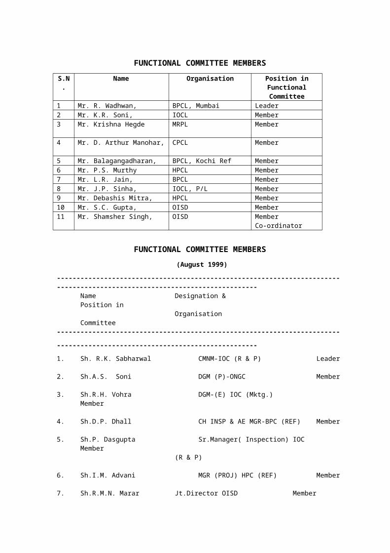
FUNCTIONAL COMMITTEE MEMBERS
S.N. Name Organisation Position in Functional Committee
1 Mr. R. Wadhwan, BPCL, Mumbai Leader2 Mr. K.R. Soni, IOCL Member3 Mr. Krishna Hegde MRPL Member
4 Mr. D. Arthur Manohar, CPCL Member
5 Mr. Balagangadharan, BPCL, Kochi Ref Member6 Mr. P.S. Murthy HPCL Member7 Mr. L.R. Jain, BPCL Member8 Mr. J.P. Sinha, IOCL, P/L Member9 Mr. Debashis Mitra, HPCL Member10 Mr. S.C. Gupta, OISD Member11 Mr. Shamsher Singh, OISD Member
Co-ordinator
FUNCTIONAL COMMITTEE MEMBERS
(August 1999)
---------------------------------------------------------------------------------------------------------------------------Name Designation & Position in
Organisation Committee---------------------------------------------------------------------------------------------------------------------------
1. Sh. R.K. Sabharwal CMNM-IOC (R & P) Leader
2. Sh.A.S. Soni DGM (P)-ONGC Member
3. Sh.R.H. Vohra DGM-(E) IOC (Mktg.) Member
4. Sh.D.P. Dhall CH INSP & AE MGR-BPC (REF) Member
5. Sh.P. Dasgupta Sr.Manager( Inspection) IOC Member(R & P)
6. Sh.I.M. Advani MGR (PROJ) HPC (REF) Member
7. Sh.R.M.N. Marar Jt.Director OISD Member Co-ordinator.
---------------------------------------------------------------------------------------------------------------------------In addition to the above, several other experts from the industry contributed in the
preparation, review and finalisation of this document.
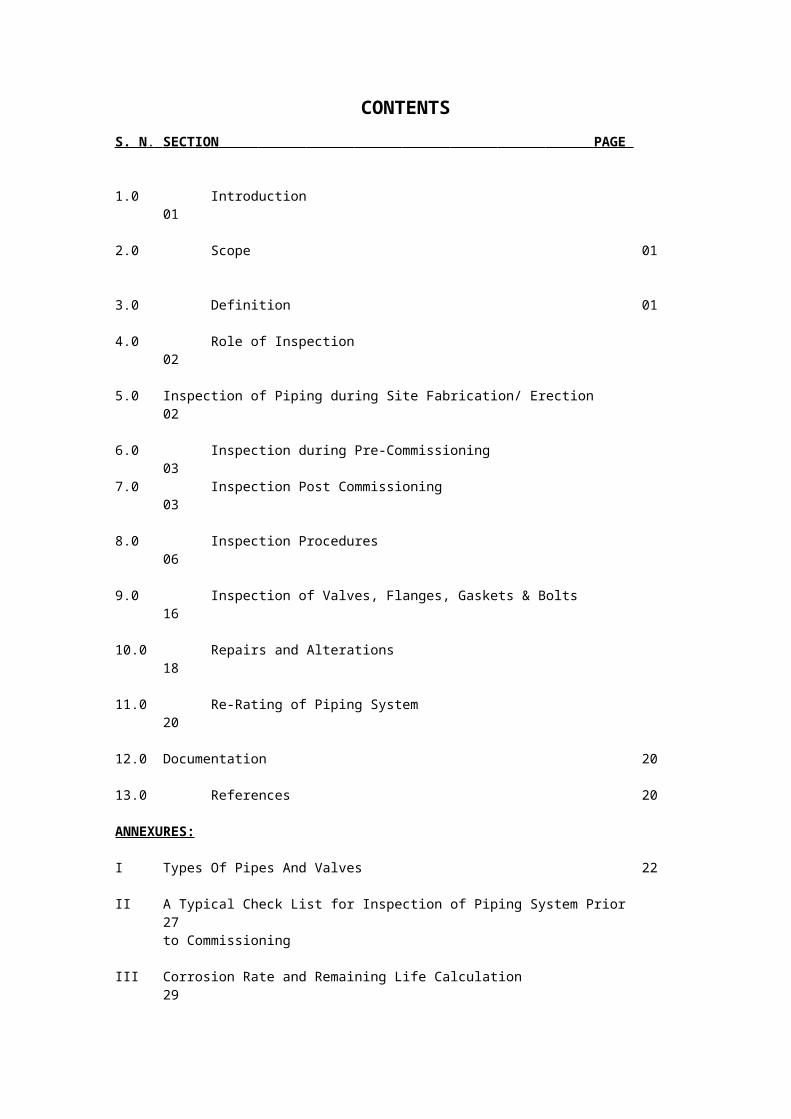
CONTENTS
S. N . SECTION PAGE
1.0 Introduction 01
2.0 Scope 01
3.0 Definition 01
4.0 Role of Inspection 02
5.0 Inspection of Piping during Site Fabrication/ Erection 02 6.0 Inspection during Pre-Commissioning 03
7.0 Inspection Post Commissioning 03 8.0 Inspection Procedures 06 9.0 Inspection of Valves, Flanges, Gaskets & Bolts 16
10.0 Repairs and Alterations 18
11.0 Re-Rating of Piping System 20
12.0 Documentation 20
13.0 References 20
ANNEXURES:
I Types Of Pipes And Valves 22
II A Typical Check List for Inspection of Piping System Prior 27to Commissioning
III Corrosion Rate and Remaining Life Calculation 29
IV A Sample List of Tools Required for Inspection 30
V A Typical Ultrasonic Thickness Survey Report Performa 31
VI Pneumatic Pressure Testing Procedure & Safety Precautions 33
VII Inspection of Small Bore Piping 38
VIII Corrosion under Insulation (CUI) 39
IX Guidelines on Flange Installation 41
X Guidelines on Gasket Installation 43
XI Likely Areas of Metal Deterioration 44
XII Material Verification Program for New and Existing Alloy 46Piping Systems
INSPECTION OF PIPING SYSTEMS
1.0 INTRODUCTION
Safety in petroleum installations comes through continuous efforts at all stages. It can be ensured by observing that plant & equipment are designed, constructed, tested and maintained as per established engineering standards; and subsequent modifications and repairs are conforming to the same standard.
2.0 SCOPE
This standard covers minimum inspection requirements, types of inspections, inspection frequencies, inspection procedures and repair methodology for metallic piping systems, including Pipes, Valves and Fittings installed in hydrocarbon industry. This standard excludes cross country and Jetty pipelines which are covered in other OISD Standards.
3.0 DEFINITIONS
3.1 AUTHORIZED PERSON
A qualified and experienced person authorized to perform piping system inspections by the owner organization.
3.2 APPLICABLE STANDARD
Applicable standard refers to the original standard of construction, unless the original standard of construction has been superseded or withdrawn from publication, in this event, applicable standard means the current edition of the appropriate standard.
3.3 DEFECT
An imperfection of a type or magnitude exceeding the acceptable criteria.
3.4 HOLD POINT
A point in the repair or alteration process beyond which work should not proceed until the required inspection has been performed and documented.
3.5 INJECTION POINT
Locations where relatively small quantities of materials are injected into process streams.
3.6 IN-SERVICE
Piping systems that have been placed in operation, as opposed to new construction prior to being placed in service.
3.7 MAXIMUM ALLOWABLE WORKING PRESSURE (MAWP)
The maximum internal pressure permitted in the piping system for continued operation at the most severe condition of coincident internal or external pressure and temperature (minimum or Maximum) expected during operation..
3.8 ON STREAM
Piping containing any amount of process fluid.

3.9 PIPE
A pressure-tight cylinder used to convey a fluid or transmit a fluid pressure.
3.10 PIPING SYSTEM
An assembly of interconnected piping that is subjected to the same sets of design conditions and is used to convey, distribute, mix, separate, discharge, meter, control or snub fluids flows. Piping system also includes pipe-supporting elements but does not include support structures, such as structural frames and foundations.
3.11 SHALL
Indicates mandatory requirement.
3.12 SHOULD
Indicates recommendation or that which is advised but not mandatory
3.13 REPAIR
The work necessary to restore a piping system to a condition suitable for safe operation at the design conditions.
4 0 ROLE OF INSPECTION
The Authorized Person(s) performing the inspections shall be qualified and experienced. The requisite criteria for deciding the qualification and experience shall be decided by the individual organization. Role of inspection personnel inter-alia is;
i) To prepare and implement piping inspection schedules to meet requisite standard, statutory and or quality requirements
ii) To measure the corrosion/ deterioration rates and to evaluate the current physical condition of the piping for soundness for continuation in service.
iii) To co-relate the corrosion/ deterioration rate with design life for further run of the piping.
iv) To investigate the causes of deterioration and recommend remedial measures, such as short term and long term repairs/ replacements.
v) To perform various stages of inspections and maintain inspection records & piping history.
5.0 INSPECTION DURING SITE FABRICATION/ ERECTION
The inspection of piping during site fabrication/ erection shall be carried our as per the requirement of applicable codes, specifications, drawings, etc. This inspection requires regular checks on the work at various stages as it progresses.
The inspection shall include:
i) Study of agreed technical specifications.
ii) Identification and inspection of material including Positive Material Identification (PMI). A write up on material verification program for new and existing alloy piping systems is attached at Annexure-XII.
iii) Developing/ checking of welding Procedure Qualification Records (PQR) in accordance with code and specifications.
iv) Approval of welding procedures specifications (WPS) in accordance with PQR.
v) Carrying out performance qualification tests for approval of Welders.
vi) Ensuring that welding is carried out as per agreed / approved procedures, by qualified welders.
vii) Inspection of weld joint fit-ups.
viii) Dye-penetrant examination of the prepared edges as specified.
ix) Ensuring proper preheating, maintaining proper inter-pass temperature and post-weld heat treatment as specified.
x) Radiographic and/ or ultrasonic inspection of weld joints as specified.
xi) Ensuring repairs of the defective welds, if any, before giving clearances for hydrostatic testing.
xii) Ensuring proper repairs to damaged lining (cement/ rubber)/ coating, if any.
xiii) Review valve test documents and retest, if required.
xiv) Ensuring all piping supports including spring supports, anchor points, guides, corrosion pads etc. are provided as per approved drawing.
xv) Hydrostatic/ pneumatic testing as specified. Mechanical clearance shall be obtained prior to hydro-testing. The base line data including thickness and type of material shall be checked and documented. The test pressure shall be maintained for not less than 30 Minutes for hydrostatic test and 10 minutes for pneumatic test.
xvi) Ensuring all approved deviations from the drawing are noted and as built drawing prepared.
xvii)Ensuring proper surface preparation and painting.
xviii) Ensuring installation of proper insulation/ internal and external coating wherever applicable.
xix) Testing of coating/ Cathodic Protection system for buried piping as specified.
A write up on types of Pipes and Valve is placed at Annexure-I.
6.0 INSPECTION DURING PRE-COMMISSIONING
The pre-commissioning inspection of piping system shall be performed to ensure that all examinations and tests during fabrication, erection and hydro-testing have been carried out. This inspection also includes the scrutiny of all the related records.
A typical checklist listing inspection checks during pre-commissioning is placed at Annexure- II.
7.0 INSPECTION POST COMMISSIONING
It is necessary to draw up and adhere to an inspection programme to avoid failures and inconveniences in operation. The authorized person(s) shall carry out the On Stream and Comprehensive Inspections. The experience and qualification of the authorized person(s) shall be in line with the applicable inspection standards and procedures.
7.1 TYPES OF INSPECTIONS
a) External On Stream Inspection
b) Comprehensive Inspection
7.2 INSPECTION INTERVAL CONSIDERATIONS
Factors responsible for determining inspection intervals of piping system include the following:
a) The nature of the fluid handled along with its pressure and temperature
b) Corrosion rates/ trends and remaining corrosion allowance
c) Condition of Corrosion protective coatings
d) Finding and recommendations at previous inspections
e) The location of piping such as isolated, high-risk and highly corrosive areas
f) The potential of air & water pollution
g) Corrosion prevention and leak detection systems
h) Applicable Statutory regulations
7.3 FREQUENCY OF INSPECTION
The piping system shall be classified based on the consequence of failures. The frequency and extent of inspection of piping system shall depend upon the form of degradation that can affect the piping performance and consequence of piping failures. This shall allow more focussed inspection regime for piping systems that have the highest potential consequences if failure or loss of containment occur
The piping system shall be categorized into 3 classes based on the severity of consequences of failure.
a) Class-I
Services with highest potential of resulting in an immediate emergency on failure. The class-I piping will cover the following services:
i) Flammable services which may auto refrigerate and lead to brittle fracture
ii) Pressurized services that may rapidly vaporize during release and form explosive mixture
iii) Gaseous stream containing more than 3% H2S by weight
iv) Hydrofluoric acid, Hydrogen service
b) Class-II
Services which are not included in other classes i.e. classes I and class III and include majority of unit process piping and selected onsite piping such as;
i) Hydrocarbon lines which will slowly vaporize during release
ii) Hydrogen, Fuel Gas and Natural Gas
iii) On-site Acids and alkalis
c) Class-III
Services which are flammable but do not significantly vaporize during leak and also not located in a high activity area. This class also includes utility and fire water lines. Class-III services are as follows:
i) Hydrocarbon lines which will not vaporize upon release
ii) Distillate and product lines to and from storage and loading
iii) Off site acids and alkalis
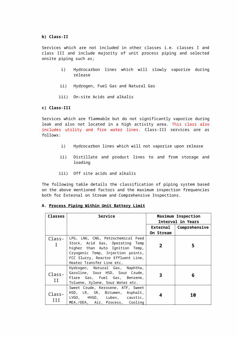
The following table details the classification of piping system based on the above mentioned factors and the maximum inspection frequencies both for External on Stream and Comprehensive Inspections.
A. Process Piping Within Unit Battery Limit
Classes Service Maximum Inspection Interval in Years
External On Stream
Comprehensive
Class-I LPG, LNG, CNG, Petrochemical Feed Stock, Acid Gas, Operating Temp higher than Auto Ignition Temp, Cryogenic Temp, Injection points, FCC Slurry, Reactor Effluent Line, Heater Transfer Line etc,
2 5
Class-IIHydrogen, Natural Gas, Naphtha, Gasoline, Sour HSD, Sour Crude, Flare Gas, Fuel Gas, Benzene, Toluene, Xylene, Sour Water etc. 3 6
Class-IIISweet Crude, Kerosene, ATF, Sweet HSD, LR, SR, Bitumen, Asphalt, LVGO, HVGO, Lubes, caustic, MEA,/DEA, Air, Process, Cooling Water and Fire Water etc.,
4 10
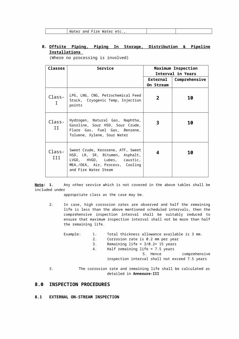
B. Offsite Piping, Piping In Storage, Distribution & Pipeline Installations (Where no processing is involved)
Classes Service Maximum Inspection Interval in Years
External On Stream
Comprehensive
Class-I LPG, LNG, CNG, Petrochemical Feed Stock, Cryogenic Temp, Injection points 2 10
Class-II Hydrogen, Natural Gas, Naphtha, Gasoline, Sour HSD, Sour Crude, Flare Gas, Fuel Gas, Benzene, Toluene, Xylene, Sour Water
3 10
Class-III Sweet Crude, Kerosene, ATF, Sweet HSD, LR, SR, Bitumen, Asphalt, LVGO, HVGO, Lubes, caustic, MEA,/DEA, Air, Process, Cooling and Fire Water Steam
4 10
Note: 1. Any other service which is not covered in the above tables shall be included under appropriate class as the case may be.
2. In case, high corrosion rates are observed and half the remaining life is less than the above mentioned scheduled intervals, then the comprehensive inspection interval shall be suitably reduced to ensure that maximum inspection interval shall not be more than half the remaining life.

Example: 1. Total thickness allowance available is 3 mm. 2. Corrosion rate is 0.2 mm per year
3. Remaining life = 3/0.2= 15 years4. Half remaining life = 7.5 years
5. Hence comprehensive inspection interval shall not exceed 7.5 years
3. The corrosion rate and remaining life shall be calculated as detailed in Annexure-III
8.0 INSPECTION PROCEDURES
8.1 EXTERNAL ON-STREAM INSPECTION
A regular inspection programme shall be drawn for on stream inspection in line with intervals mentioned above in 7.3. Piping in onsite areas should also be inspected on the run, subject to feasibility as permitted by process parameters (fluid, pressure and temperature). Any abnormalities noticed during inspection shall be investigated and corrective steps initiated at the earliest. External On-stream inspection to monitor deterioration shall be visual and instrument-aided (ultrasonic, radiographic, thermographic).
A sample list of tools required for piping inspection is attached at Annexure-IV.
The likely area of metal deterioration are described in Annexure-VIII
8.1.1 Visual Inspection
i) Leaks
Visual inspection shall be made to locate leaks. Particular attention should be given to pipe connections, the packing glands of valves and expansion joints.
ii) Alignment
The piping shall be inspected for misalignment. The following are some observations which may indicate misalignment:
a) Pipe dislodged from its support so that the weight of the pipe is distributed unevenly on the hangers or the saddles.
b) Deformation of the wall of the vessel in the vicinity of the pipe attachment.
c) Pipe supports forced out of plumb by expansion or contraction of the piping.
d) Shifting of base plate or shearing of the foundation bolts of mechanical equipment to which the piping is attached.
e) Cracks in the connecting flanges or pump casings and turbines to which the piping is attached.
iii) Supports
Pipe supports shall be visually inspected for the following:
a) Condition of protective coating or fire proofing if any. If fire proofing is found defective, sufficient fire proofing should be removed to determine extent of corrosion.
b) Evidence of corrosion
c) Distortion

d) General physical damage
e) Movement or deterioration of concrete footings.
f) Condition of foundation bolts.
g) Free operation of pipe rollers.
h) Secure attachment of brackets and beams to the supports.
i) Secure attachment and proper adjustment of pipe hangers, if used. Spring hangers loading shall be checked both cold and hot and the readings obtained shall be checked against the original cold and hot readings. The movement of spring supports shell be monitored.
j) Broken or otherwise defective pipe anchors.
k) Free operation of pulleys or pivot points of counter balanced piping system.
iv) Vibration
a) If vibrations or swaying is observed, inspection, shall be made for cracks in welds, particularly at points of restraint such as where piping is attached to equipment and in the vicinity of anchors. Additional supports should be considered for poorly braced small size piping and valves and for main vibrating line to which they are attached.
b) In case of severe vibration, detailed investigations shall be carried out to determine the source of problems.
v) External Corrosion
Inspection of piping for external corrosion shall be carried out.
vi) Bulging, Bowing and Sagging
Line shall be checked for bulging, bowing and sagging in between the supports.
vii) Mechanical Damage from External Forces
Pipes shall be inspected for dents, scratched etc. from external sources.
viii) Paint and Protective Coating
Conditions of paint and protective coating shall be checked.
ix) Cracks
Pipelines shall be inspected for cracks. Particular attention should be given to areas near the weld joints.
x) Insulation
Damage of insulation shall be checked for hot as well as cold lines.
xi) Concrete Lining
Externally concrete lined piping shall be visually inspected for cracking and dislodging of concrete.
8.1.2 Ultrasonic Thickness Survey
Ultrasonic thickness survey of the pipelines shall be carried out to ascertain the wall thickness. The following procedure shall be followed for the above-ground pipelines.
i) Minimum three readings shall be taken on the bends of the piping network at the outer curvature. One reading shall be at the centre of the bend and two readings on the same line on either side of this reading.
ii) Minimum one ultrasonic scan each on the straight pipes on upstream and downstream of the bend adjacent to welds of the bend to pipe. One ultrasonic scan consists of four readings (3, 6, 9 and 12 o'clock positions). For pipelines in which there is a possibility of ballast water coming, one ultrasonic scan will consist of six readings (3, 5, 6, 7, 9 and 12 o'clock positions) to scan the bottom portions.
iii) One ultrasonic scan on the entire circumference (four readings) upstream and downstream of the weld joint for process pipelines.
iv) Minimum one ultrasonic scan (four readings) each on reducer/ expander and just downstream on the pipe.
v) One ultrasonic scan on the pipe downstream of valves orifices, etc.
vi) One ultrasonic scan minimum on horizontal pipe for every three meters length at lower elevations where possibilities of collection and stagnation of carryover water, or acid condensation or SO2 flow exist.
vii) Branch connection, dead ends, etc, shall be checked by ultrasonic thickness survey for corrosion and erosion.
viii) Necessary work permit shall be taken as per OISD-STD-105 while carrying out thickness survey.
ix) The details of thickness survey shall be maintained on an isometric sketch. A typical ultrasonic thickness survey report performa is attached at Annexure V.
In case half the remaining life, based on established corrosion rate, is more than the
period required for next comprehensive inspection, then the ultrasonic thickness inspection should be clubbed with next comprehensive inspection.
Long range ultrasonic guided wave technology should be deployed to assess metal loss in inaccessible location not covered under conventional ultra sonic thickness measurement.
8.1.3 Radiographic Inspection
Critical spots, which cannot be inspected by ultrasonic instruments accurately, shall be radiographed during operation to determine wall thickness as well as internal condition like fouling, scaling, etc. Insulation need not be removed for radiographic inspection. Critical spots where weld-joints, nipples/ small diameter deadlines are welded, which cannot be inspected ultrasonically shall be radiographed to determine their internal condition.
Conventional radiography at times is slow and needs evacuations of persons during exposures and thus results in man hour loss. Digital Radiography can quickly detect pipe wall thinning due to erosion / corrosion.
8.1.4 Corrosion Probes
One of the methods of measuring internal corrosion rate of unit piping or offsite piping is by installing corrosion probes for measuring corrosion rates. Important pipe lines like overhead line can be monitored using corrosion probes. If installed the readings shall be taken periodically to establish the deterioration rate.
8.1.5 Corrosion Coupons
Corrosion coupons should be installed in the important and critical pipelines to measure internal corrosion rate. The coupons are taken out after a specified period and thoroughly cleaned. The weight loss of coupons over a specified period gives the internal corrosion rate of the pipes.
8.2 COMPREHENSIVE INSPECTION
A regular inspection programme shall be drawn for comprehensive inspection in line with intervals mentioned above in 7.3. Comprehensive inspection of pipelines shall include external inspections as covered above in 8.1. In addition, the following inspections shall be part of comprehensive inspection of piping systems.
a) All piping which cannot be checked on the run shall be inspected during shutdown. These are mostly high temperature piping. During shutdown inspection, hammer-testing and hydro-testing as applicable should be carried out in addition to visual, ultrasonic and radiographic inspections.
b) Pipelines in some of the services like phenol and steam are prone to pitting corrosion. Neither ultrasonic nor radiographic testing reveals the actual internal condition of the pipes in such service. In such cases samples shall be cut for thorough internal examination, at scheduled comprehensive inspections. The samples shall be spilt open in two halves and internal surfaces inspected for pitting, grooving, etc.
c) The internally strip lined bends and pipes shall be visually examined for bulging, weld cracking, weld, defects, etc. Thickness of the strip shall be measured to find out thinning of the strips.
d) Austenitic SS piping, where there is a chance of stress corrosion cracking due to formation of polythionic acid, shall be kept in inert atmosphere. Passivation of the austenitic SS piping shall be done as per NACE-RP-01-70, if all these are to be opened to the atmosphere.
8.2.1 Inspection for Corrosion, Erosion and Fouling
Piping shall be opened at various locations by removing valves at flanged locations to permit visual inspection. When erratic corrosion or erosion conditions are noted in areas accessible for visual examination, radiographic examination or ultrasonic testing shall be performed to determine thickness. This is applicable to piping which cannot be inspected during operation. The nature and extent of internal deposits shall be noted. Samples should be collected for chemical analysis.
8.2.2 Inspection for Cracks
Welds, heat-affected areas adjoining welds, points of restraint cracking, hydrogen attack and caustic embrittlement shall be inspected for cracks. For spot checks, dye-penetrant or magnetic particle inspection should be used. Alloy and stainless steel piping need close inspection. In-situ metallography at critical spots may be also done. Magnifying glass should be used for crack detection.
8.2.3 Inspection of Gasket Faces of Flanges
The gasket faces of flange joints which have been opened shall be inspected visually for corrosion and for defects such as scratches, cuts and grooving which might cause leakage. Ring gaskets and joints shall be checked for defects like dents, cuts, pitting and grooving.
8.2.4 Inspection of Hot Spots
Where hot spots on internally lined pipe are noted during operation, the internal lining shall be inspected visually for failure. The pipe wall at the hot spot shall be inspected visually for oxidation and scaling. The scales shall be removed to expose bare metal and the area checked for cracks. The thickness of the metal shall be measured to ensure that sufficient thickness is left for the service. The outside diameter of piping in high temperature service shall be measured to check for creep deformation.
8.2.5 Hammer Testing
Hammer testing shall also be carried out to supplement visual and ultrasonic inspection. While hammer testing, the following precautions shall be taken:
i) Hammer testing of valves, pipes and fittings of cast iron construction, chrome-steel, austenitic SS lines and stress relieved lines shall not be carried out.
ii) Care shall be taken not to hammer so hard as to damage otherwise sound piping.
iii) Hammer testing shall not be performed on glass-lined, cement-lined or otherwise internally coated lines.
iv) Hammer testing shall not be done on operating lines and lines under pressure.
8.2.6 Pressure Testing
a) Pressure testing of existing pipelines shall be carried out in the following conditions;
i) After any major alteration / re-rating / replacement
ii) Inaccessible piping and complicated manifold
iii) System after chemical cleaning
iv) When the piping is out of service for more than six months
b) Austenitic stainless steel piping shall be hydro-tested using water with chloride content less than 50 PPM.
c) All newly installed piping shall be pressure tested prior to commissioning.
d) Hammer testing of piping undergoing a pressure test shall not be carried out.
e) Stress due to testing shall not exceed 90% of the yield stress of the material of construction of the piping.
f) Pressure test shall not be carried out at metal temperatures near the ductile-to-brittle transition temperature of the material.
A. Hydro-Test Pressure and Procedures
Except where it is necessary to meet design codes or statutory requirements, the hydrostatic test pressure should be limited to 125% of design pressure. Pressure shall be
applied in small increments. The following points shall be considered while carrying out hydrostatic testing.
i) All floats shall be removed before filling the system with water.
ii) All air present in the system shall be vented while admitting the test fluid.
iii) Piping designed for vapour and gas shall be provided with additional temporary supports, if necessary. All spring support shall be kept in locked position during hydro-test.
iv) Line containing check valves shall have source of test pressure on the upstream side.
v) Valves shall not be subjected to a test pressure in excess of manufacturer's allowable test rating. When permitted, the installed valves shall be kept open.
vi) Control and relief valves shall be excluded from the test irrespective of their pressure rating.
vii) Instrument take-off piping up to the first block valve shall be tested along with piping to which it is connected. Testing of remaining line leading up to the instrument can also be done at the same time provided instruments are blocked off from the source of pressure and vented to atmosphere.
viii) Open ends of piping where blanks cannot be used e.g. pumps, compressors, etc. shall be blinded off by using standard blind flanges of same rating as the piping system being tested.
ix) Indicating pressure gauges mounted locally may be tested with the line, provided the test pressure is not in excess of their scale ratings.
x) Orifice plates in horizontal lines shall not be installed till completion of test.
xi) The test shall be carried out at ambient temperature and it should be less than 50 deg. C.
xii) All vent valves during filling up and draining shall be kept fully open.
xiii) Hydrostatic testing of ferritic material shall be carried out using suitably inhibited water, which permits an extended period between the start of testing and drying of components.
xiv) Hydrostatic testing of austenitic material shall be carried out using water chloride content less than 50 PPM.
B. Pneumatic Test Pressure and Procedure
Pneumatic testing shall be considered where hydro-testing is not possible due to design or service requirements. The consequences of failure during a pneumatic test can be devastating and such testing requires special precaution. Pneumatic testing shall be carried out in line with proven standards/ codes. The pneumatic test procedure shall be duly approved. Some of the precautions to be taken are as follows:
i) The piping shall be subjected to thorough testing including NDT as considered necessary to ensure that there are no inherent defects / operating deterioration which may cause failure of piping during testing.
ii) Except where it is necessary to meet design codes or statutory requirements, the test pressure should be limited to 110% of design pressure. Pressure shall be applied in small increments.
iii) Close visual examination of piping shall not be resorted to at a pressure higher than the design pressure.
The pneumatic pressure testing procedure & safety precautions to be taken are detailed at Annexure-VI.
8.3 INSPECTION OF PIPING IN CORROSIVE STREAMS
i) Hydrogen Sulphide (H2S) Service
The weld joints for this service where H2S content is more than 50 PPM, shall be stress relieved after fabrication. Weld joints at random shall be checked for suspected cracking. If the line is not thermally insulated, external thickness measurements shall be taken for suspected internal corrosion. When the line is not in operation, magnetic testing method will help in locating cracks in the welds.
ii) Di-Ethyl Amine/ Mono-Ethyl Amine Service
Pipelines carrying DEA/ MEA are prone to internal corrosion and stress corrosion cracking. All newly constructed piping shall be stress relieved irrespective of the strength and temperature of the chemicals. All carbon and low alloy steel weld joints shall be inspected for cracks using wet fluorescent magnetic particle test. External thickness measurements shall be taken at all bends and other flow-restrictions for determining the internal corrosion rate. All socket-welded and seal-welded threaded connections are prone to stress corrosion cracking if not stress-relieved. Hammer testing of the line shall not be carried out as it may induce localised stresses.
iii) Hydrogen Service
Carbon steels are prone to hydrogen embrittlement at elevated temperatures above 232 deg C. Pipelines shall be checked for blistering and distortion whenever shut down for inspection.
iv) Phenol Service
Carbon steel resists phenolic corrosion up to 205 deg C provided water is not present. Corrosion in phenol is very erratic. However, when it occurs, it may be very severe. All bends and areas of high velocity and where turbulent conditions occur shall be ultrasonically inspected. However, areas which cannot be inspected ultrasonically shall be radiographed to ascertain their internal condition.
v) Caustic (Sodium Hydroxide) Service
Caustic is non-corrosive at atmospheric temperatures to carbon steel. Caustic will cause stress corrosion cracking above 94 deg C and hence all carbon steel lines shall be stress-relieved before commissioning or after repairs. Lines shall be checked for embrittlement and metal loss.
vi) Chlorine Service
Chlorine, though not so corrosive in gaseous phase, becomes highly corrosive in presence of moisture. Rubber-lined carbon steel pipes are generally used in chlorine services. Rubber-lined, pipes shall be checked for bulging of lining at bends, flanges or at weld joints.
vii) Acid Service
Sulphuric acid is corrosive in dilute phase. Hydrochloric acid is corrosive at all concentrations while phosphoric acid is corrosive when it mixes with water in carbon steel pipes. The following locations shall be checked for acid corrosion in carbon steel lines:
a) Horizontal sections of the line where dilute-acid stagnation may occur.
b) Section of the line at bends where elbows tend to corrode due to turbulent acid attack.
c) Section of the line adjacent to orifices, reducers, expanders, etc.
d) Caustic neutralisation injection points and T-joints due to turbulence.
e) Heat affected zones of weld joints due to residual stress concentrations and thermo- galvanic effects.
f) Locations where temperatures are more than 50 deg C.
8.4 INSPECTION OF HIGH TEMPERATURE PIPING
Inspection shall be made for hot spots on internally lined piping. Any bulging or scaling shall be noted for further inspection when the piping is under shut down. Some hot spots can be detected by a red glow, particularly if inspection is made in the dark. Portable infrared pyrometer or temperature indicating crayon shall be used to determine the skin temperatures. Sometimes thermographic survey of internally lined hot piping helps in locating the hot spots. Furnace transfer lines and column bottom lines, which are operating at very high temperatures, shall be inspected at every shutdown. Insulation shall be removed at specified locations including all bends and ultrasonic thickness shall be carried out and the corrosion rate established. Spring hangers and spring supports of high temperature piping shall also be checked during shutdown.
8.5 INSPECTION OF UNDERGROUND PIPING
For Inspection of underground piping, special care is required to be given due to significant external deterioration caused by corrosive soil condition. Underground piping is mainly checked off-stream. However, development of exigencies may require inspection of the same on the run after exposing the line.
If any industrial effluent is flowing over ground, where piping are laid or any environmental change is noticed, the soil samples shall be tested to check the corrosive nature of soil and to determine the efficacy of the existing coating and wrapping of the piping.
8.5.1 Types of Underground (U/G) Piping
i. U/G Piping with Coating & Wrapping
ii. U/G Piping with Coating & Wrapping and Cathodic Protection
8.5.2 U/G Piping with Coating & Wrapping
Most of the underground process pipelines are coated with suitable coating materials to protect these pipelines against external deterioration caused by corrosive soil condition.
a. These pipelines shall be inspected once in five years by using the suitable Coating Surveys such as Pearson Survey, Current Attenuation Technique (CAT), Direct Voltage Gradient Survey (DCVG) etc. These coating surveys would locate the coating damage, if any. Based on the survey results, coating refurbishment jobs to be taken and post coating survey may also be conducted to ensure the proper coating & wrapping of the piping.
b. All these lines shall be visually inspected at random once in ten years by digging at a few locations. After excavation, the coating and wrapping shall be examined both visually be by holiday detector. Pipelines crossing the roads and dykes shall also be inspected once in ten years by digging and exposing the line completely.
c. Fouling, if any, shall be detected by Radiographic/ NDT examination.
d. Ultrasonic thickness measurements shall be carried out on the surface of the pipe after removing a band of wrapping and coating.
e. The stray current interference of underground pipe, if any, shall be checked by Cu-CuSO4
half-cell. The incidence of stray current interference is high in the underground portion of cathodically protected and non-cathodically protected piping separated by insulated flanges or couplings. This current causes severe damage in the unprotected line if the coating and wrapping is damaged. This location shall be inspected once a year by exposing the insulating flanges or couplings.
f. All lines shall be inspected at and just before the point where they enter the earth or concrete slab.
8.5.3 U/G Piping with Coating & wrapping and Cathodic Protection:
Few of the underground process pipelines are having wrapping and coating as well as cathodic protection to mitigate the external soil corrosion. Cathodic protection for mitigation of external corrosion is achieved by reversing natural corrosion current with the supply of current from external source and ensuring that current flows through electrolyte into the whole metal surface that requires protection. The external current supply in cathodic protection system is generated either by sacrificial anode or impressed current system.
In addition to the checks/ inspection given in 8.5.2, following checks/ inspection shall be carried out for underground piping with cathodic protection.
a. Impressed current Cathodic Protection, if installed, parameters such as input Voltage & current, output voltage & current, PSP at nearest Test lead point shall be checked monthly.
b. The Pipe to Soil Potential (PSP reading) at the test lead points for entire under ground piping shall be taken once in a quarter. The PSP survey results shall be plotted graphically to identify and locate unprotected stretch of pipeline. The minimum pipe to soil potential shall be more negative than - 0.85 volts (polarised potential) with respect to copper/copper sulphate half cell.
c. Over protection of coated pipelines shall be avoided by ensuring that polarisation potential (Off Potential) is below - 1.1 volts with respect to copper/ copper sulphate half cells.
d. Close Interval Potential Survey (CIPS) performed at ground level over the underground piping can be used to locate active corrosion points on the pipe’s surface. CIPS shall be carried out at 5 years intervals.
e. All buried or submerged coated piping system shall be electrically isolated at interconnections from the other lines which are not cathodically protected.
8.6 INSPECTIONS IN SPECIFIC AREAS FOR CORROSION AND CRACKING
The piping systems are susceptible to the following specific types of areas and deteriorations and require special attention;
i) Injection Points
Injection points are sometimes subject to accelerated or localized corrosion from normal or abnormal operating conditions. Therefore, these should be treated as separate inspection circuits, and these areas need to be inspected thoroughly.
When designating an injection point circuit for the purposes of inspection, the recommended upstream limit of the injection point circuit is a minimum of 12 inches (300mm) or three pipe diameters upstream of the injection point, whichever is greater. The recommended downstream limit of the injection point circuit is the second change in flow direction past the injection point, or 25 feet (7.6 m) beyond the first change in flow direction, whichever is less. In some cases, it should be more appropriate to extend this circuit to the next piece of pressure equipment.
The selection of thickness measurement locations (TMLs) within injection point circuits subject to localized corrosion should be in accordance with the following guidelines:
a.Establish TMLs on appropriate fittings within the injection point circuit.
b. Establish TMLs on the pipe wall at the location of expected pipe wall impingement of injected fluid.
c. TMLs at intermediate locations along the longer straight piping within the injection point circuit should be required.
d. Establish TMLs at both the upstream and downstream limits of the injection point circuit.
The preferred methods of inspecting injection points are radiography and/or ultrasonics, as appropriate, to establish the minimum thickness at each TML. Close grid ultrasonic measurements or scanning should be used, as long as temperatures are appropriate.
For some applications, it is beneficial to remove piping spools to facilitate a visual inspection of the inside surface. However, thickness measurements shall still be required to determine the remaining thickness.
During periodic scheduled inspections, more extensive inspection should be applied to an area beginning 12 inches (300mm) upstream of the injection nozzle and continuing for at least ten pipe diameters downstream of the injection point. Additionally, measure and record the thickness at all TMLs within the injection point circuit.
ii) Deadlegs
The corrosion rate in deadlegs can vary significantly from adjacent active piping. The wall thickness should be monitored on selected deadlegs, including both the stagnant end and at the connection to an active line. In hot piping system, the high point area may corrode due to convective currents set up in the deadleg. Consideration should be given to removing deadlegs that serve no further process purpose.
iii) Corrosion under insulation (CUI)
External inspection of insulated piping systems should include a review of the integrity for the insulation system for conditions that could lead to corrosion under insulation and for signs of ongoing CUI. Sources of moisture may include rain, water leaks, condensations, and deluge systems. The most common forms of CUI are localized corrosion of carbon steel and chloride stress corrosion cracking of austenitic stainless steels. A write up on Corrosion under insulation is placed at Annexure-IX.
iv) Soil to Air Interface
Soil-to-air interfaces for buried piping without adequate cathodic protection shall be included in scheduled external piping inspections. Inspection at grade should check for coating damage, bare pipe, and pit depth measurements. If significant corrosion is noted, thickness measurements and excavation should be required to assess whether the corrosion is localized to the S/A interface or may be more pervasive to the buried system. Thickness readings at S/A interfaces may expose the metal and accelerate corrosion if coatings and wrappings are not properly restored. If the buried piping has satisfactory cathodic protection as determined by monitoring excavation is required only if there is evidence of coating or wrapping damage. If the buried piping is uncoated at grade, consideration should be given to excavating 6 inches to 12 inches (150mm to 300mm) deep to assess the potential for hidden damage.
At concrete-to-air and asphalt-to-air interfaces of buried piping without cathodic protection, the inspector should look for evidence that the caulking or seal at the interface has determined and allowed moisture ingress. If such a condition exists on piping systems over 10 years old, it may be necessary to inspect for corrosion beneath the surface before resealing the system.
v) Fatigue cracking
Fatigue cracking of piping systems may result from excessive cyclic stresses that are often well below the static yield strength of the material. The cyclic stresses may be imposed by pressure, mechanical, or thermal means and may result in low cycle or high cycle fatigue. The onset of low cycle fatigue cracking is often directly related to the number of heat up and cool down cycles experienced. Excessive piping system vibration (such as machine or flow induced vibrations) also can cause high cycle fatigue damage.
Fatigue cracking can typically be first detected at points of high stress intensification such as branch connections. Locations where metals having different coefficients of thermal expansion are joined by welding may be susceptible to thermal fatigue. Preferred NDE methods of detecting fatigue cracking include liquid penetrant testing or magnetic particle testing. Acoustic emission also may be used to detect the presence of cracks that are activated by test pressures or stresses generated during the test.
It is important to understand that fatigue cracking is likely to cause piping failure before it is detected with any NDE methods. Of the total number of fatigue cycles required to produce a failure, the vast majority are required to initiate a crack and relatively fewer cycles are required to propagate the crack to failure. Therefore, proper design and installation in order to prevent the initiation of fatigue cracking are important.
9.0 INSPECTION OF VALVES, FLANGES, GASKETS & BOLTS
9.1 Valves
Steel gate valves, steel globe valves, flanged cast iron gate valves, threaded and socket welded valves, soft-seated ball valves -`Fire Safe Type', plug valves, check valves and butterfly valves for water service are used in Petroleum installations. A write up on types of pipes and valve is placed at Annexure-VII.
9.1.1 Inspection and Testing of New Valves
All new valves shall be inspected and tested at the manufacturer’s premises to ensure conformation to required specifications and for leak tightness as per requirements of the design code and records maintained thereof.
(a) Valves in Hydrogen Service
All low alloy valve castings in hydrogen service with a hydrogen partial pressure of 100 Psi (7 Kg/cm2) shall be 100% magnetic particle and radiographically examined. Helium Leak Test shall be done for body, bonnet, cover joints and stuffing box.
(b) Valves in Wet H2S Service
Valves made of steel containing phosphorus or sulphur in excess of 0.03% shall not be used in H2S service.
Hardness of the body, bonnet and gate and weld metal and HAZ of any pressure retaining part shall not exceed the limits given below:-
Material Brinell hardness,
P-1 225P-3, P-4, P-10, P12 225P-5, P-6, P-7 225 Inconel, Precipitation Hardened 310
(c) Fire Safe Type Ball Valves
i) Low pressure seat test shall be conducted with the ball and seat dry and free of oil, grease or any lubricant. In addition, the high pressure seat test shall be conducted for threaded valves.
ii) Fire-safe type test shall be carried out as per the design code for qualifying the manufacturer’s design.
9.1.2 Inspection of Valves in Service
a) Valves, flanges, gaskets and bolts in erosive/ highly corrosive services and those showing obvious signs of deterioration shall be dismantled to permit examination of all internal parts for carrying out repairs/ replacement as necessary. The frequency of such inspections shall be determined by the user based on service conditions.
b) Valves operating in severe cyclic temperature service shall be checked internally for cracks.
c) Gate valves, which have been used for throttling, shall be checked for metal loss at the bottom between the seats. The seating surface shall be inspected visually for defects which might cause leakage. The wedging guides shall be inspected for corrosion and erosion. The stem and threads on the stem and in the bonnet of valves shall be examined for corrosion. The connection between stem and disc shall be inspected for wear and tear.
d) Swing check valves shall be inspected by removing the cover or cap. The flapper
or disc shall be checked for freedom of rotation and the nut holding it to the arm shall be checked for security and presence of a locking pin, lock washer, or tack weld. The arm should be free to swing and the anchor pin shall be inspected for wear. Also the seating surface on both the disc and valve body shall be checked for deterioration. After the valve has been reassembled, it shall be hydrostatically and/or pneumatically tested for tightness.
9.2 Flanges, Gaskets and Bolts
i) The markings on a representative sample of newly installed fasteners and gaskets should be examined to determine weather they meet the material specifications. Questionable fasteners should verified or renewed.
ii) Fasteners should extend completely through their nuts.
iii) If installed flanges are excessively bent, their markings and thicknesses should be checked against engineering requirements before taking corrective actions.
iv) Flange and valves bonnet fasteners should be examined visually for corrosion.
v) Flanged and valve bonnet joints should be examined for evidence of leakage, such as stains, deposits or drips. Process leaks on to flange and bonnet fasteners may result in corrosion or environmental cracking.
vi) Flanged joints that have been clamped and pumped with sealants should be checked for leakage at the bolts. Fasteners subjected to such leakage may corrode or crack (caustic cracking for example). If re-pumping is contemplated, affected fasteners should be renewed first.
vii) Fasteners on instrumentation that are subject to process pressure and / or temperature should be included in the scope of these examinations.
viii) The guidelines for Flange Installation and Gasket Installation are included at Annexure-VI
10.0 REPAIRS AND ALTERATIONS
a) The thickness reduction, damages etc. shall be ascertained to determine adequacy for continued service in line with the design standards. In case of pipeline sections fail to qualify the minimum requirements, affected sections of the pipeline shall be replaced or repaired in line with the design code.
b) Painting, insulation, wrapping and coating shall be done as per the design code
c) All repair and alteration work shall be authorised and approved.
10.1 Repairs by Welding
10.1.1 Temporary Repairs
a) Temporary repairs, including on stream or off stream, a full encircle split sleeve or box type enclosure designed to take care of internal pressure can be considered over damaged or corroded area. Area with longitudinal cracks shall not be repaired by encircle sleeve.
b) If repair area is small and localized, temporary repair may be carried out using properly designed split coupling or fillet plate patch. The material of repair will match with base metal.
c) Areas with minor leaks shall be attended by welding of properly designed enclosures. If repairs are to be carried out in-service then it has to be ensured that adequate thickness is available in the vicinity of welding and piping component can withstand welding without the likelihood of further material damage.
d) Temporary repairs shall be removed and replaced with permanent repairs at the next available maintenance opportunity. Temporary repairs may remain in place for a longer period of time only if approved and documented.
10.1.2 Permanent Repairs
a) All repairs and alteration welding shall be done in accordance to the code to which the piping system has been built.
b) Repairs to defects in piping component can be made by preparing a groove that completely removes the defects and then filling the groove with weld metal deposits.
c) Corroded areas may be restored with weld deposits. However, Surface irregularities and contaminations shall be removed before welding.
d) Insert plates may be used to repair the damaged or corroded areas provided following are met;
i) Full penetration groove welds
ii) 100% radiography of joints for hydrocarbon/ critical service
iii) Insert patch shall have rounded corners
e) During out of service repair, the defective area shall be removed by cutting the cylindrical sections and replacing it with piping component which meet the code requirement.
f) Wherever excessive corrosion/ erosion is observed at support locations, consideration may be given to attaching a pipe pad at support locations for enhancing life of pipeline.
10.2 Non Welding Repairs
a) Clamping: Temporary repairs of locally thinned out sections or circumferential linear defects can be made on stream by installing a properly designed and fabricated bolted clamps. The effect of clamping (crushing) forces on the component shall be considered.
b) Composite Sleeves: Non-leaking corroded area and certain other types of defects may be repaired by the installation of composite sleeve provided that design and installation method are proven for the intended service prior to application. Composite sleeves shall not be used to repair leaks, metal loss with a depth greater than 80% of the nominal wall thickness, cracks, or circumferentially oriented defects.
10.3 INSPECTION DURING REPAIRS / REPLACEMENTS
Following points shall be considered during repair / replacement of piping;
a) The metallurgy and dimensions of the new pipe shall match with those of the existing pipe.
b) Repairs shall be carried out by a qualified welder using approved welding procedures.
c) For longitudinally welded pipes, the weld seam shall be kept staggered and the longitudinal seam shall be kept in the upper quadrants.
d) Piping systems repair work shall comply with applicable statutory requirements.
e) Repaired welds shall be subject to same pre and post-weld heat treatments as required in the case of new pipes.
11.0 RE-RATING OF PIPING SYSTEM
Re-rating piping systems by changing the temperature rating or the MAWP shall be done only after all the following requirements are met;
i) All re-rating shall be established in accordance with the requirements of the code to which the piping system was built or by computing using the appropriate methods in the latest edition of the applicable code.
ii) Current inspection records verify that the piping system is satisfactory for the proposed service conditions and that the appropriate corrosion allowance is provided.
iii) Re-rated piping system shall be leak tested in accordance with the code to which the piping system was built or the latest edition of the applicable code for the new service conditions, unless documented records indicate a previous leak test was performed at a greater than or equal to the test pressure for the new conditions. An increase in the rating temperature that does not affect allowable tensile stress does not require a leak test.
iv) Piping system shall be checked to affirm that required pressure relieving devices are present; are set at appropriate pressure; and have the appropriate capacity at set pressure.
v) All piping components in the system, such as valves, flanges, bolts, gaskets, packing, and expansion joints are adequate for the new combination of pressure and temperature.
vi) Piping flexibility is adequate for the design temperature changes.
vii) Appropriate engineering records are updated.
viii) A decrease in the minimum operating temperature is justified by impact test results, if required by the applicable code.
12.0 DOCUMENTATION
Isometrics/ piping plan of each circuit as per actual site conditions shall be prepared. The records shall be maintained to give information like:
i) Identification of particular piping systems in terms of location, class, total length, material specification, general process flow and service condition and location of corrosion probes, if any.
ii) Location of thickness measurement points, replacement carried out, corrosion rate, etc.
iii) An isometric sketch for guidance has been given in Annexure-V. All small connections shall be clearly shown on isometrics and piping drawings.
iv) All testing and inspection records shall be maintained.
v) On the basis of records of previous and present inspection, a work schedule shall be prepared for future on stream as well as comprehensive inspections.
13.0 REFERENCES
The following standards, codes and publications have either been referred to or used in the preparation of this document and this standard shall be read in conjunction with the same
i) API 570, Piping Inspection Code (Inspection repair, alteration, and rerating of in-service piping systems)
ii) ANSI B 31.3 Chemical Plant and Petroleum Refinery Piping
iii) ASA B 36.10 Welded Seamless Wrought Steel Pipe.
iv) ASA B 36.19 Stainless Steel Pipe.
v) NACE RP 01-69.
vi) NACE RP-01-70.
vii) NACE RP-01-75.
viii) ASME 31 G
ix) Piping Handbook-Crocker and King.
x) API RP 574, Inspection of Piping System Components
xi) API 579 : Recommended Practice for Fitness-For-Service and Continued Operation of Equipment
Annexure-I
TYPES OF PIPES AND VALVES
1 Electric Resistance Welded Pipes
Pipes produced in individual lengths or in continuous lengths from coiled skelp and subsequently cut into individual lengths having a longitudinal or spiral butt joint wherein coalescence is produced by the heat obtained from resistance of the pipe to the flow of electric current in a circuit of which the pipe is a part, and by the application of pressure.
2 Electric Fusion Welded Pipes
Pipe having a longitudinal butt joint wherein coalescence is produced in the preformed tube by manual or automatic electric-arc welding. The weld may be single or double side welded and may be with or without the use of filler metal.
3 Double Submerged Arc Welding Pipes
Pipe having a longitudinal butt joint produced by at least two passes, one of which is on the inside of the pipe. Coalescence is produced by heating with an electric arc or arcs between the bare metal electrode or electrodes and the work. The welding is shielded by a blanket of granular fusible material on the work. Pressure is not used and filler metal for the inside and outside welds is obtained from the electrode or electrodes.
4 Spiral Welded Pipes
Pipe having a helical seam with butt joint which is welded using an electrical resistance, electric fusion or double submerged arc welding (DSAW) process.
The submerged welding process protects the steel from contamination of impurities in the air. Both inside and outside welds are performed. DSAW pipe can be specified in very large diameter and to exact inside or outside dimensions. Spiral Welded steel pipe is distinguished by the manufacturing process that results in a spiral DSAW seam the length of the pipe to lengths of 155 feet.
5 Seamless Pipes
Seamless steel pipes are used for steam boilers and pipelines, installations with high and supercritical steam conditions. These pipes and tubing are manufactured by commercial, electric furnace bearing, consumable, electrode vacuum melted quality steel. These impart strength and durability to the pipes and thus can be used for corrosion-resisting applications. Ultra high strength and corrosion-resistant properties makes these perfect for oil & gas industry and chemical industry.
6. Types of Valves
Although many different types of valves are used to control the flow of fluids, the basic valve types can be divided into two general groups: stop valves and check valves.
Besides the basic types of valves, many special valves, which cannot really be classified as either stop valves or check valves, are found in the engineering applications. Many of these valves serve to control the pressure of fluids and are known as pressure-control valves. Other valves are identified by names that indicate their general function, such as thermostatic re-circulating valves.
The following sections deal first with the basic types of stop valves and check valves, then with some of the more complicated special valves.
A. Stop Valves
Stop valves are used to shut off or, in some cases, partially shut off the flow of fluid. Stop valves are controlled by the movement of the valve stem. Stop valves can be divided into four general categories: globe, gate, butterfly, and ball valves. Plug valves and needle valves may also be considered stop valves.
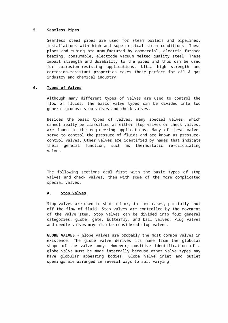
GLOBE VALVES.- Globe valves are probably the most common valves in existence. The globe valve derives its name from the globular shape of the valve body. However, positive identification of a globe valve must be made internally because other valve types may have globular appearing bodies. Globe valve inlet and outlet openings are arranged in several ways to suit varying
Figure: 1 - Types of globe valve bodies.
requirements of flow. Figure-1 shows the common types of globe valve bodies: straight flow, angle-flow, and cross flow.
GATE VALVES.- Gate valves are used when a straight-line flow of fluid and minimum restriction is desired. Gate valves are so named because the part that either stops or allows flow through the valve acts somewhat like the opening or closing of a gate and is called, appropriately, the gate. The gate is usually wedge shaped. When the valve is wide open, the gate is fully drawn up into the valve, leaving an opening for flow through the valve the same size as the pipe in which the valve is installed. Therefore, there is little pressure drop or flow restriction through the valve. Gate valves are not suitable for throttling purposes since the control of flow would be difficult due to valve design and since the flow of fluid slapping against a partially open gate can cause extensive damage to the valve. Except as specifically authorized, gate valves should not be used for throttling.
Gate valves are classified as either RISING-STEM or NON RISING-STEM valves. On the non rising-stem gate valve shown in figure-2 the stem is threaded on the lower end into the gate. As the handwheel on the stem is rotated, the gate travels up or down the stem on the threads, while the stem remains vertically stationary. This type of valve almost always has a pointer-type indicator threaded onto the upper end of the stem to indicate valve position.
Figure 2.-Cutaway view of a gate valve (non-rising-stem type).
The rising-stem gate valve, shown in figure has the stem attached to the gate; the gate and stem rise and lower together as the valve is operated.
Gate valves used in steam systems have flexible gates. The reason for using a flexible gate is to prevent binding of the gate within the valve when the valve is in the closed position. When steam lines are heated, they will expand, causing some distortion of valve bodies. If a solid gate fits snugly between the seat of a valve in a cold steam system, when the system is heated and pipes elongate, the seats will compress against the gate, wedging the gate between them and clamping the valve shut. This problem is overcome by use of a flexible gate (two circular plates attached to each other with a flexible hub in the middle). This design allows the gate to flex as the valve seat compresses it, thereby preventing clamping.
BUTTERFLY VALVES.- The butterfly valve, one type of which is shown in figure -3 may be used in a variety of systems aboard ship. These valves can be used effectively in lube oil, and chill water systems. The butterfly valve is light in weight, relatively small, relatively quick-acting, provides positive shut-off, and can be used for throttling.
The butterfly valve has a body, a resilient seat, a butterfly disk, a stem, packing, a notched positioning plate, and a handle. The resilient seat is under compression when it is mounted in the valve body, thus making a seal around the periphery of the disk and both upper and lower points where the stem passes through the seat. Packing is provided to form a positive seal around the stem for added protection in case the seal formed by the seat should become damaged.
Figure -3.-Cutaway view of a gate valve (rising-stem type).
Figure -4.-Butterfly valve.
.
To close or open a butterfly valve, turn the handle only one quarter turn to rotate the disk 90°. Some larger butterfly valves may have a hand wheel that operates through a gearing arrangement to operate the valve. This method is used especially where space limitation prevents use of a long handle.
Butterfly valves are relatively easy to maintain. The resilient seat is held in place by mechanical means, and neither bonding nor cementing is necessary. Because the seat is replaceable, the valve seat does not require lapping, grinding, or machine work.
BALL VALVES.- Ball valves, as the name implies, are stop valves that use a ball to stop or start the flow of fluid. The ball (fig 5) performs the same function as the disk in the globe valve. When the valve handle is operated to open the valve, the ball rotates to a point where the hole through the ball is in line with the valve body inlet and outlet. When the valve is shut, which requires only a 90-degree rotation of the hand wheel for most valves, the ball is rotated so the hole is perpendicular to the flow openings of the valve body, and flow is stopped.
Figure-5.-Typical seawater ball valve.
Most ball valves are of the quick-acting type (requiring only a 90-degree turn to operate the valve either completely open or closed), but many are planetary gear operated. This type of gearing allows the use of a relatively small hand wheel and operating force to operate a fairly large valve. The gearing does, however, increase the operating time for the valve. Some ball valves contain a swing check located within the ball to give the valve a check valve feature.
Annexure-II
A TYPICAL CHECK LIST FOR INSPECTION OF PIPING SYSTEM PRIOR TO COMMISSIONING
The checklist format shall include the following information;
i) Pipe sketch No/ Drg. No. :ii) Location :iii) Service :iv) Material :v) Dimensions Dia & Thk. :vi) Max. allowable working pressure:vii) Max. allowable working temp. :viii) Stress relief :ix) Radiography :x) Hydrostatic test pressure :xi) Insulation :xii) Internal lining :xiii) Underground protection :xiv) Erection contractor :xv) Contractor's inspector :xvi) Company's inspector :xvii) Date of inspection :
CHECK LIST
CHECK REMARKS
1.0 Check documentation like PMI, PQR, WPS and Welders test records.
2.0 Check stage inspections including joint fit ups, filler metals
and pre/ post weld heat treatment, radiography, other NDT tests and hydro test.
3.0 Check and inspect small connections e.g. drains and vents
4.0 Check and inspect all threaded connections for proper
5.0 Engagement of threads, back welding and gusseting
6.0 Check for any alteration/deviation from the drawing during construction.
7.0 Check base line data including wall thicknesses/ material.
8.0 Check and ensure installation of specified gaskets, especially at the untested joints.
9.0 Check installation and ensuring set pressure of pressure relieving devices.
10.0 Check correct installation (direction) of check/ globe/control valves.
11.0 Check proper bolting of flange joints.
12.0 Check for proper alignment of supports (on pipe-racks or sleepers)
13.0 Check steam tracings and steam traps.
14.0 Check for tension free jointing of suction and discharge piping connected to rotary
equipment
15.0 Check painting for Dry Film Thickness (DFT).
16.0 Check insulation for proper installation/ sealing etc
17.0 Check records of coating on buried pipelines for bonding/ thickness/ holiday testing.
18.0 Check for proper hook-up with cathodic protection system wherever applicable.
.
Annexure-III
CORROSION RATE AND REMAINING LIFE CALCULATION
The process/ procedure for Corrosion Rate calculation/ estimation shall be duly approved.
A. Remaining life of the in service piping system shall be calculated as per the following procedure
Corrosion Rate = T (previous) – T (present) ----------------------------- Time between present and previous inspections
T (previous) – Thickness reading taken during inspection
T (present) -- Thickness reading taken at present
Remaining life (Years) = T (actual) – T (minimum) ----------------------------- Corrosion RateWhere:
T (actual) = Actual minimum thickness
T (minimum) = Minimum required thickness
Calculation of Minimum Required Thickness (T (minimum))
Minimum required thickness for carbon steel and alloy steel under internal pressure shall be calculated as per the following procedure:
T (Minimum) = P X D ------------- (2 SE + 2 YP)
Where P = Design Pressure / Max. allowable working Pressure D = Outside diameterS = Allowable stress at design temperature E = Joint Efficiency Y = Coefficient that takes material properties and design temperature
into account
C. For new piping system and for piping system for which service conditions are being changed, the probable corrosion rate for determination of remaining life shall be determined using following method.
i) Corrosion rate for a piping system may be calculated from data collected on the piping system of similar material and service
ii) If data on similar material or service is not available, then it can be estimated from published data
iii) If corrosion rate can not be established from above, the thickness determination shall be made within 3 months of service by thickness measurement of the piping system. Subsequent measurements shall be made after appropriate intervals until corrosion rate is established.
Annexure-IV
A SAMPLE LIST OF TOOLS REQUIRED FOR INSPECTION
The following tools may be used as aids for carrying out pipeline inspection.
1. Portable Alloy Analyser
2. Ultrasonic thickness meter
3. Ultrasonic Flaw Detector
4. Magnetic Particle Testing kit
5. Dye Penetrant testing kit
6. Radiography equipment
7. Radiography Film Viewer
8. Radiation Survey meter
9. Metallographic Replica Kit
10. Microscope (100X) / Magnifying glass
11. Portable Hardness tester
12. Infrared Pyrometer / Contact Thermometer / Thermal Crayans
13. Thermal Imaging camera
14. Ag-AgCl / Cu-CuSO4 Half-cell.
15. Holiday Detector
16. Inspector’s hammer.
17. Paint and coating thickness gauge.
18. Pit depth gauge.
19. Magnet.
20. Safety torches.
21. Crayons.
22. Small mirror
23. Photography camera
24. Vernier Caliper
25. ID / OD Calipers
26. Ferrite Meter
Annexure-V
A TYPICAL ULTRASONIC THICKNESS SURVEY REPORT PERFORMA
ANNEXURE -VI
PNEUMATIC PRESSURE TESTING PROCEDURE & SAFETY PRECAUTIONS
1. INTRODUCTION
This annexure specifies requirements and gives recommendations for on-site pneumatic pressure testing of piping system.
Pneumatic pressure testing is a dangerous operation since the amount of energy contained in air under pressure is 200 times more than the energy contained in water at the same pressure and volume.
Hydrostatic pressure testing is the safer method and shall be used wherever practicable.
Pneumatic testing shall be considered only in the following cases:
Piping system which cannot safely be filled with liquid due to their design or supports
Piping system where traces of testing medium (liquid) is not permitted in the process
This annexure does not replace the leak test methods that may be specified by the design code
2. SCOPE
In general, pressure tests are carried out to prove the mechanical strength and integrity of piping systems. The piping codes require a hydrostatic pressure test but, under special conditions, may permit a pneumatic test instead.
Local regulations shall be adhered to unless exemption has been granted.
Unless otherwise specified by the design code, pneumatic pressure testing shall be performed at the following test pressures:
Individual Components 1.1 x Design Pressure of component
Systems 1.1 x Design Pressure of the weakest component in the system
3. TERMINOLOGY
For the purposes of this document the following terms shall be used:
3.1 Pneumatic pressure test:
A test carried out using air or inert gas to prove the integrity of a component or system, at a pressure specified by the design code.
3.2 Pneumatic leak test
A test carried out using air or inert gas at low pressure for the detection of gross leaks. For the detection of small leaks, the gas used is nitrogen traced with helium and detection is by a probe connected to a mass spectrometer. Such tests may be undertaken without observing the full safety precautions required for a pneumatic pressure test.
NOTE: “Low pressure” means a pressure less than 2 bar (ga) or 10% of the design pressure, whichever is less.
4. SAFETY CONSIDERATIONS
4.1 General
Pneumatic testing on an operating plant may be performed only under the following conditions :
All local and national safety regulations shall be strictly followed unless an exemption has been granted by the authorities concerned.
The test procedure in compliance to design code shall be prepared and shall be approved.
Personnel barricades shall be erected at a distance indicated below :
Test Pressure(gauge)
Personnel barricade radius
1 bar 350 m10 bar 500 m
100 bar 700 m
The perimeter of the barricaded area shall be clearly signposted with appropriate warning signals and shall be patrolled during the test.
The site shall be clear of personnel not directly associated with the test
Adequate fire and safety crews shall be available.
ALL NDT required by the design code shall have been completed and fully accepted.
Even if not required by the design code, all welds shall have been ultrasonically or radio graphically examined and all base materials other than carbon steel shall have undergone a positive material identification (PMI).
Where bellows are installed in the test circuit, special precautions shall be taken to prevent over-pressurizing the equipment.
A pressure relief valve and a pressure gauge shall be installed on the equipment to be tested and on the compressors/gas cylinder delivering the pressure.
The pressure gauges shall have accuracy as specified in the design code and shall have a scale range of between 1.5 and 3 times the test pressure.
No valves shall be installed between the piping system under test and the pressure gauges.
The gas to be used for testing shall be non-flammable.
4.2 Brittle fracture
The possibility of brittle fracture shall be considered when conducting a pneumatic pressure test at metal temperatures near the ductile/brittle transition temperature of the metal. Pneumatic pressure testing shall not be performed when the equipment metal temperature is less than 55 deg.0C above the reference nil ductility temperature (RT NDT). Furthermore, regardless of the nil ductility temperature, pneumatic pressure testing should not be performed at an ambient temperature below 7 0C.
Pressure shall be introduced gradually into the system allowing adequate time for temperature equalization. The Joule-Thompson effect shall be taken into account.
NOTE : The Joule-Thompson effect causes a temperature reduction and occurs when high pressure gas (e.g. nitrogen) enters the system and its pressure drops.
4.3 Bolt tightening
No bolting work shall be performed during a pneumatic pressure test. If bolting needs to be tightened (e.g. due to a flange leak) then the system shall first be depressurized.
4.4 Temporary / flexible tube connections
Temporary and/or flexible tube connections shall not be used unless they are manufactured and certified specifically for the service intended. The end connections shall be suitable rated and inspected for mechanical damage.
4.5 Bellows
Thrust forces and design test pressure shall be checked prior to testing.
4.6 Cautionary notes
1. If the piping system should fail during pneumatic pressure test, other equipment in the vicinity may be damaged. If critical equipment is located within the distances indicated below, then it should be considered not to perform the pneumatic pressure test or to provide protection for the other equipment.
Test Pressure(gauge)
Distance within which equipment damage can be expected
1 bar 15 m10 bar 70 m
100 bar 175 m
2. Nitrogen or inert gas can asphyxiate personnel. Therefore in the event of major leak, an inert gas leak test should always be preceded by a gross leak test using air.
3. Personnel in affected areas should wear breathing apparatus due to possible low oxygen levels.
5. PROCEDURE FOR PNEUMATIC PRESSURE TESTING
5.1 Approval for testing
The decision to permit pneumatic pressure testing instead of hydrostatic pressure testing shall be taken by the authorized person.
5.2 Test plan
A test plan shall be prepared and shall include at least :
The scope of work;
The type of pneumatic test to be performed, i.e. pressure test or leak test;
The necessary skill groups to be involved;
An inspection plan;
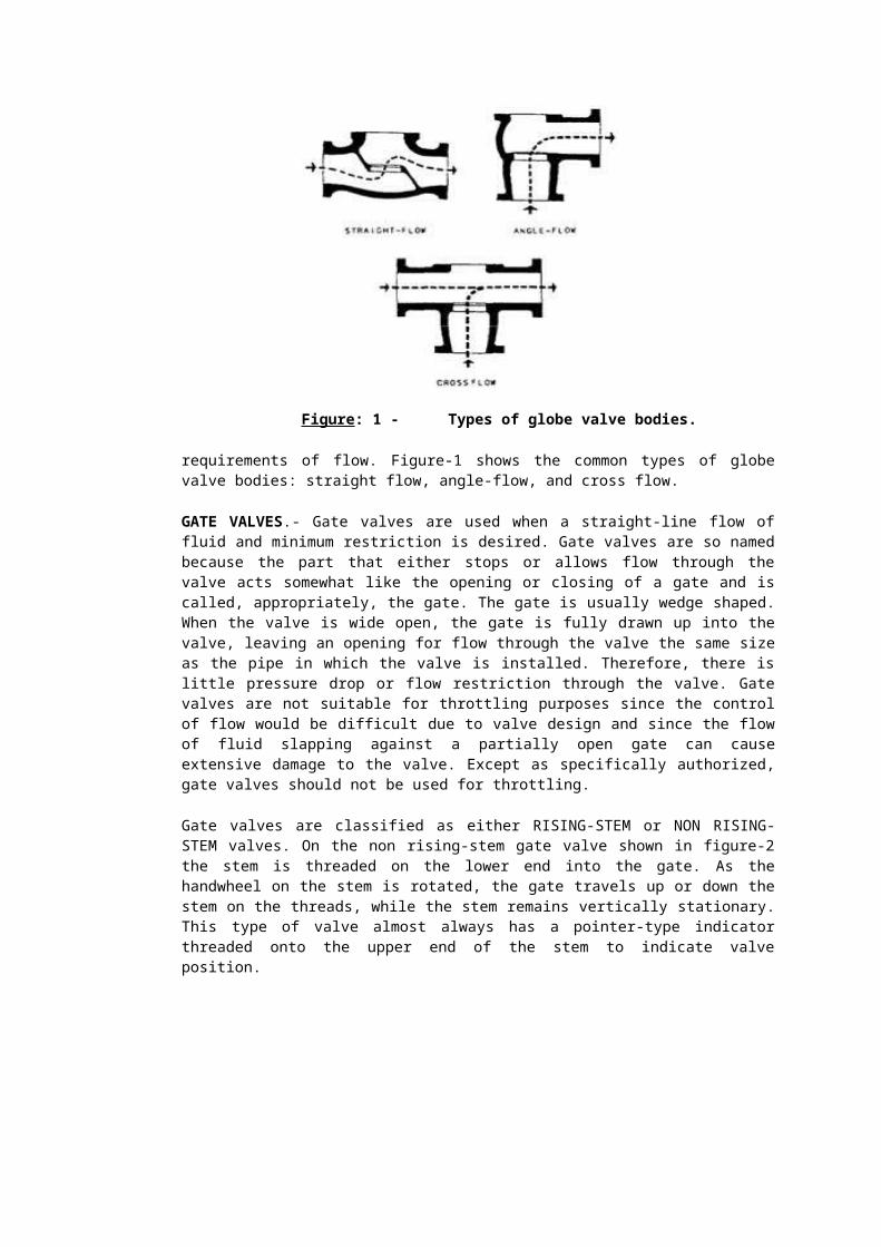
Details of the leak detection methods and acceptance criteria;
A test schedule
5.3 Safety plan
A safety plan shall be prepared and shall include at least:
Safety considerations;
The gas to be used as test fluid;
Required minimum test temperature;
Special equipment in the system to be tested, e.g. bellows, valves etc.;
Required records and data;
Safety distances;
Inform relevant authorities and organize safety services.
5.4 Review and approval of test and safety plans
The pneumatic pressure test shall commence only after the test and safety plans have been approved.
5.5 Performance of pneumatic pressure test
The following measures shall be taken :
The relevant authorities shall be informed if necessary.
The system or test equipment shall be protected by a pressure relieve device having a set pressure of 10% above the pneumatic test pressure of the system.
The system to be tested shall be correctly isolated.
All valves shall be in the open position.
Testing shall not be performed in wet weather. Screens or other wind protection shall be provided if the test could otherwise be impaired.
The pressure shall be gradually increased to not more than 50% of the test pressure, at which time a preliminary check shall be made, including examination of joints. Thereafter, the pressure shall be gradually increased in steps of 10% until the test pressure is reached, holding the pressure at each step for sufficient time to allow the temperature and strain to stabilize. The pressure shall then be reduced to the design pressure, at which time the joints shall be examined using liquid soap.
Venting shall be to a safe location.
De-pressurizing shall be done gradually, avoiding pressure shocks.
All findings shall be recorded.
5.6 Documentation
The method and sequence of testing shall be fully documented. Annexure- VII
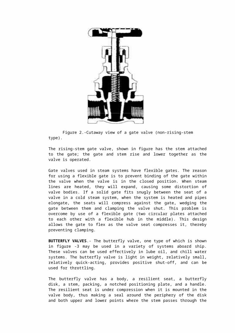
INSPECTION OF SMALL BORE PIPING
Inspection of small bore piping (SBP) may be missed due to their smaller size or may be neglected or overlooked. However, they have the potential, to cause major safety incidents in case of leakage / failure. Hence, small-bore piping deserves equal if not greater attention during inspection of plant piping and equipment. The details of these SBPs may not be shown in the process flow diagrams but physically exists in the field.
Piping less than or equal to NPS 2” is considered as small bore piping. The vents, drains in the main piping system, auxiliary instruments and machinery connections and threaded connections and dead legs fall in the category of SBP.
It is recommended a master listing and tagging and plan of small-bore piping and dead legs shall be made for inspection and maintenance be made in each operating unit, especially for all piping containing flammable and toxic fluids even if the fluids are non-corrosive. These SBPs and dead legs should then be baseline inspected by various means, including visual testing (after insulation removal, if necessary), thickness scanning, OD callipering, radiography, DP testing of welds, material identification (PMI) etc., until sufficient confidence is obtained regarding integrity or replacement can be recommended.
The failure of SBP may be due to the following reasons:
The main piping may be handling a mildly corrosive fluid with a low likelihood of failure. However, the corrosive constituent may settle and get concentrated in the low point drains due to the dead leg effect.
The corrosive constituent may be in vapour form in the run piping may condense in high point vents (dead leg location) and thus these areas may be preferentially attacked.
The small-bore piping may fail due to CUI (Corrosion Under Insulation) as perfect water proofing is intricate to do at the small branch connections / branches. Any breakage in external cladding will allow moisture / water ingress. It is also important to regularly monitor the condition of the insulation sealant, as the sealant may crack due to thermal movements or degradation due to ageing. Corrosion is particularly severe at insulation / bare interfaces
Vibrations: Fatigue failure to SBP may occur due to vibration without any noticeable internal or external corrosion. Additional support is necessary wherever required. Small bore connections are more vulnerable to failure due to vibrations due to their smaller diameter than the main run pipe. Also majority of small bore connections such as low point drains and high point vents have a cantilever type configuration and hence it is imperative that small bore connections prone to vibrations should be properly supported to mitigate vibration damage.
External corrosion on SBP due to moisture collection and embedded in soil particularly in the drain points of culvert pipelines.
Many of the small-bore connections, particularly vents and drains, are provided during the plant / unit construction phase for line flushing, pressure testing and / or commissioning. They may not serve any useful purpose after the plant is in operation. All such redundant connections should be eliminated in consultation with the Plant Operations group to avoid future leakages / failures.
Higher Schedule pipes and fittings than as specified in the piping specification may be considered for SBP for extended life.
Annexure- VIII
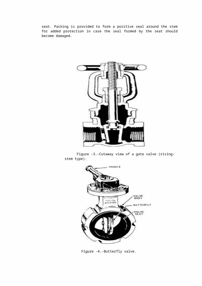
CORROSION UNDER INSULATION (CUI)
Corrosion of piping and structural components resulting from water trapped under Insulation or fire proofing.
A. Common areas of attack are;
i) Process units in high moisture areas such as areas adjacent to cooling towers, near steam vents, deluge systems etc.
ii) Process equipment with damaged insulation, vapour barriers, weatherproofing or coating damage.
iii) Process equipment designed with Insulation support rings welded directly to the vessel wall particularly around ladder and platform clips, lifting lugs, nozzles and stiffener rings.
iv) Piping or equipment with damaged/ leaking steam tracing
v) Localised damage to Paint/ coating system.
vi) Carbon Steel piping systems operating between –4 deg-c to 120 deg-c.
vii) Carbon Steel piping systems operating above 120 deg-c but are in intermittent service.
viii) Dead legs (vents, drains) and attachments that protrude from the insulated piping and operate at a different temperature than the main piping.
ix) Austenitic Stainless Steel piping operating between 65 deg-c to 204 deg-c
x) Vibrating piping that may damage insulation and provide a path for water ingress.
xi) Irregular insulation surfaces like valves and fittings
xii) Areas adjacent to Pipe supports.
xiii) Soil to air Inter face for buried Piping where possibility of a coating damage may result in moisture ingress.
B. Prevention/ Mitigation Measures Include:
i) Usage of appropriate coatings/ Paintings and proper Insulation to prevent water ingress.
ii) Low Chloride Insulation material on 300 series SS to minimize potential for Chloride SCC.
iii) A review of Insulation requirement of equipment. Those that need not be insulated should be left bare.
iv) A structured and systematic approach to identifying potential areas susceptible to CUI.
v) Adopt following NDT techniques:
Partial/ full stripping of insulation for visual inspection of Equipment/ Piping. Corrosion becomes more severe at metal temperatures between 100 deg-c to 120 deg-c where water is less likely to evaporate and tends to stay wet. Carbon steel piping systems, that normally operates above 120 deg-c but is in intermittent service. Dead legs and attachments from piping systems that are insulated. These
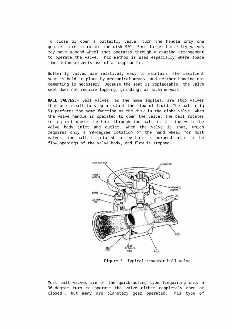
may operate at a different temperature than the operating temperature of the main line.
Ultrasonic thickness measurements.
Thermography: It is the use of infrared imaging and measurement equipment to see and measure the thermal energy emitted from an object/ system. Areas of application of this technique as an Inspection tool are as follows. Areas of application include:
a) To detect Corrosion under insulation in piping systems.
b) To detect Corrosion under insulation in Static equipment.
c) Inspection of Stacks lined with cast-able (Incinerator Stacks in SRU)
d) Inspection of Reformer and Heater tubes for locating hot spots (Hydrogen Reformers and Process heaters in units).
e) To identify the location of blocked piping etc
Guided wave Ultrasonic measurement
Eddy Current Measurement to locate external Chloride SCC
f) Develop a unit specific Inspection plan to identify the location susceptible to corrosion under insulation for pressure vessels and check for corrosion by removing the insulation at the location suspected during the turn around. It can be carried out on sample basis in such a way that all the identified locations get inspected at least once in 12 years.
Ultrasonic measurements (manual or automated) from the inside of a vessel can be attempted. This saves the labour/ time involved in Insulation removal but may not be as accurate as a
thorough external visual inspection after insulation removal.
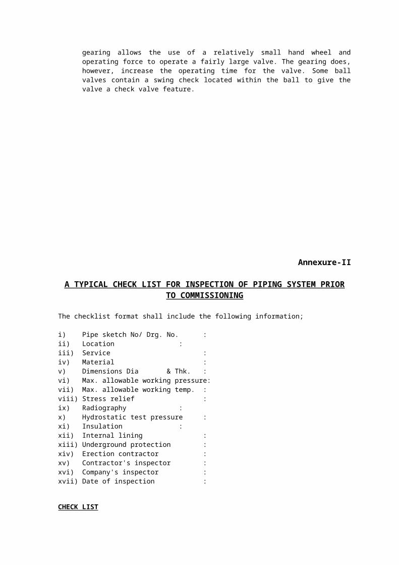
Annexure-IX
GUIDELINES ON FLANGE INSTALLATION
a) Always wear appropriate safety equipment
b) Check gasket for flange type and surface finish on which to be used
c) Check the gasket I.D. It should be no greater than the flange I.D.
d) Flanges shall be free of pits, gouges, rust, debris, oil and grease.
e) Check flange and bolt hole spot facings for burrs, etc.
f) Check bolts and nuts and clean. Apply non-conductive lubricant to all threads and flange side of nuts.
g) Align flanges so they are concentric and parallel and install gasket carefully. USE NO LUBRICANT, GREASE OR ADHESIVES ON EITHER THE GASKET OR FLANGE FACES,
h) Line up bolt holes with non-tapered drift pins using three at 120° degrees separation (particularly large flanges), or at least two at 180° degrees separation.
i) Insert bolt sleeves. Do not force. If force is needed, recheck alignment and for sleeve damage. Follow up with studs, nuts and washers, placing lubricated face of nut next to steel washer (this will help to reduce galling of the insulating washer on flange, should the whole bolt assembly rotate).
j) Initially cross-tighten bolts until flange to gasket contact has been made.
k) Check for a flange segment that may show a gap or separation between gasket and flanges, using flashlight, calipers, or feeler gauge. If one exists, the flanges are not parallel.
l) Directly 180° degrees opposite widest part of indicated gap, loosen nuts, even if only finger tight, one or more turns. Return to segment with gap and tighten until both flanges are in contact with gasket retainer. This procedure is necessary to prevent restriction of flange rotation over the fulcrum formed by the outer edge of the two raised faces at points in contact with gasket retainer. The restriction will cause exceptionally high flange to gasket clamp loading at this point, with possible damage to gasket retainer, PLUS diverting necessary clamp loading bolt torque energy to correcting alignment on the opposite segment.
m) Re-tighten loosened nuts and proceed with torqueing of the bolts according to PSI diagram, to 10-15% of specified torque. Remove drift pins and replace with bolts, nuts and washers, tightened to the same values as others in place.
n) Repeat torque sequence, increasing to 50% of balance.
o) Repeat tightening to final torque.
p) Optional – it is always a good policy to go completely around flange checking bolt to bolt for proper torque, particularly on large diameter piping systems.
q) All the above should be done with torque wrenches (mechanical and hydraulic) or with a stud tension measuring device.
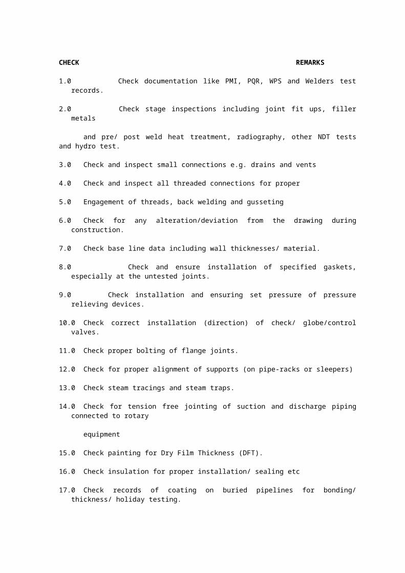
Note:
When installing gaskets made of compressible dielectric material and tightened cold; “hot flow” of the gasket material may occur under operating conditions, resulting in loss of bolt pressure. It is advisable therefore, to retighten bolts after operating temperature has been reached – preferably at zero line pressure and ambient temperature. Under no circumstances should the system be allowed to return to operating temperature after the initial cycling to ambient temperature without checking and re-tightening bolts where needed.

Annexure - X
GUIDELINES ON GASKET INSTALLATION
Gasket installation procedure is essential for assuring joint integrity and maximum safety. This write-up is intended to complement other plant-approved installation procedures which are in practice.
A. Tools required
Specific tools are required for cleaning and tensioning the fasteners. Additionally, always use standard safety equipment and follow good safety practices. Following are some of the tools required for this job.
Calibrated torque wrench,
hydraulic or other tensioner
Wire brush (brass if possible)
Helmet
Safety goggles
Lubricant
Other plant-specified equipment
B. Procedure
i) Remove all foreign material and debris from:
Seating surfaces
Fasteners (bolts or studs)
Nuts
Washers
ii) Use plant-specified dust control procedures
iii) Examine
Examine fasteners (bolts or studs), nuts and washers for defects such as burrs or cracks
Examine flange surfaces for warping, radial scores, heavy tool marks, or anything prohibiting proper gasket seating
Replace components if found to be defective. If in doubt, seek advice
iv) Align flanges; Align flange faces and bolt holes without using excessive force ! Report any misalignment
v) Install gasket;
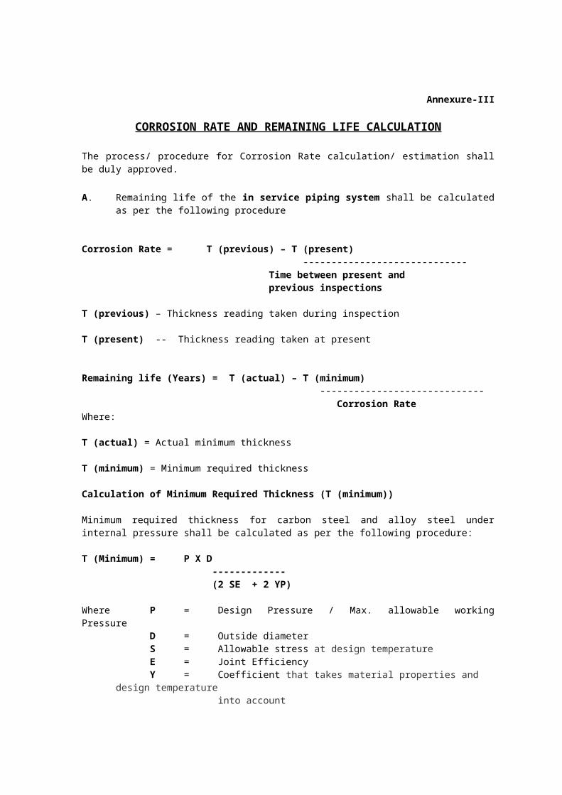
Ensure gasket is the specified size and material
Examine the gasket to ensure it is free of defects Carefully insert the gasket between the flanges
Make sure the gasket is centred between the flanges
Do not use jointing compounds or release agents on the gasket or seating surfaces unless specified by the gasket manufacturer
Bring flanges together, ensuring the gasket isn’t pinched or damaged
vi) Lubricate load-bearing surfaces
Use only specified or approved lubricants
Liberally apply lubricant uniformly to all thread, nut and washer load-bearing surfaces
Ensure lubricant doesn’t contaminate either flange or gasket face
vii) Install and tighten fasteners
Always use proper tools: calibrated torque wrench or other controlled tensioning device
Consult your gasket manufacturer for guidance on torque specifications
Always torque in a cross bolt tightening pattern
Tighten the nuts in multiple steps
Step 1 - tighten all nuts initially by hand (larger bolts may require a small hand wrench
Step 2 - torque each nut to ~30%of full torque
Step 3 - torque each nut to ~60% of full torque
Step 4 - torque each nut to full torque, again still using the cross bolt tightening pattern (larger diameter flanges may require additional tightening passes)
Step 5 - apply at least one final full torque to all nuts in a clockwise direction until all torque is uniform (larger diameter flanges may require additional passes)
viii) Re-tightening
Caution: consult your gasket manufacturer for guidance and recommendations onre-tightening
Do not re-torque elastomer based, asbestos-free gaskets after they have been exposedto elevated temperatures unless otherwise specified ! Re-torque fasteners exposed to aggressive thermal cycling ! All re-torquing should be performed at ambient temperature and atmospheric pressure
Annexure-XI
LIKELY AREAS OF METAL DETERIORATION
A. EXTERNAL CORROSION
The following areas of piping are prone to external corrosion.
i) Above piping ground is subject to atmospheric corrosion.
i) Pipelines touching the ground are subject to corrosion due to dampness of the soil.
ii) Crevice corrosion may take place at the pipe supports or sleepers where pipes are resting on them.
iii) Deterioration takes place at the pipe support locations where relative movement between pipe and pipe supports takes place.
iv) Buried pipelines are subject to soil corrosion.
v) Underground pipelines are subject corrosion due to presence of stray currents.
vi) Impingement attack may take place on pipelines in the vicinity of leaky pipes and steam traps.
vii) Insulated lines where weather shielding is damaged are subject to external corrosion.
viii) Austenitic stainless steel lines where chlorides can leach from external thermal insulation due to water are subject to stress corrosion cracking.
ix) Externally concrete-lined pipelines are subject to localised corrosion due to cracks in the concrete.
x) Piping entering into or emerging from the underground may experience severe corrosion due to coating damage.
xi) Piping corrodes at locations of water accumulation and acid vapour condensation such as in the vicinity of fire hydrants sulphur recovery plants, cooling towers, jetty, etc.
B INTERNAL CORROSION
Usually a greater loss of metal wastage is observed near a restriction in the line or a change in line direction because of the effects of turbulence or velocity. Therefore, is required to inspect pipe bends, elbows, and tees and also at restrictions such as orifice flanges and throttling valves, and areas just down steam of the restriction.
Areas most prone to corrosion, erosion, and other forms of deterioration are :
i) Points at which condensation of acid gases and / or water vapour are likely to occur.
ii) Points at which acid carryover from process operations are likely to occur.
iii) Points at which naphthenic or other organic acids may be present in the process stream.
iv) Points at which high sulphur streams of moderate to high temperature exists.
v) Points at which high temperature and low temperature hydrogen attack may occur.
vi) Dead-ends and locations where liquid-vapour inter phasing or condensation occur.
vii) Valve bodies and trims, fittings, ring grooves and rings, flange faces and unexposed threads.
viii) Welded areas (subject to preferential attack).
ix) Catalyst, flue gas, and slurry piping.
x) Steam systems subject to channelling or where condensation occurs.
xi) Ferrous and non-ferrous piping subject to stress corrosion cracking.
xii) Alkali lines subject to caustic embrittlement with resultant cracking at stressed areas such as weld joints, bends, etc.
xiii) Areas near flanges or welded attachments, which act as cooling fins, thereby causing localised corrosion because of condensation.
xiv) Locations where fluid impinges or fluid velocity changes.
xv) Chrome-Nickel and chrome-molybdenum lines in high temperature service near points of increased stress such as bends and anchor points.
xvi) Areas where steam or electric tracing come in contact with pipes handling materials such as caustic soda.
xvii) Austenitic stainless steel lines where polythionic acid formation takes place with resultant cracking.
xviii) Areas immediately downstream of chemical injection points where localised corrosion might occur in the reaction zone.
xix) Dissimilar metals in contact, which may lead to galvanic corrosion.
xx) Rubber-lined and glass-lined pipes which may get damaged near the flanges or due to cracks in the lining.
xxi) Stagnant conditions in areas of pipelines carrying crude oils with high sulphur/chloride content.
xxii) Terminal pipelines carrying sea/ ballast water.
xxiii) Locations having low pit and high chloride ions.
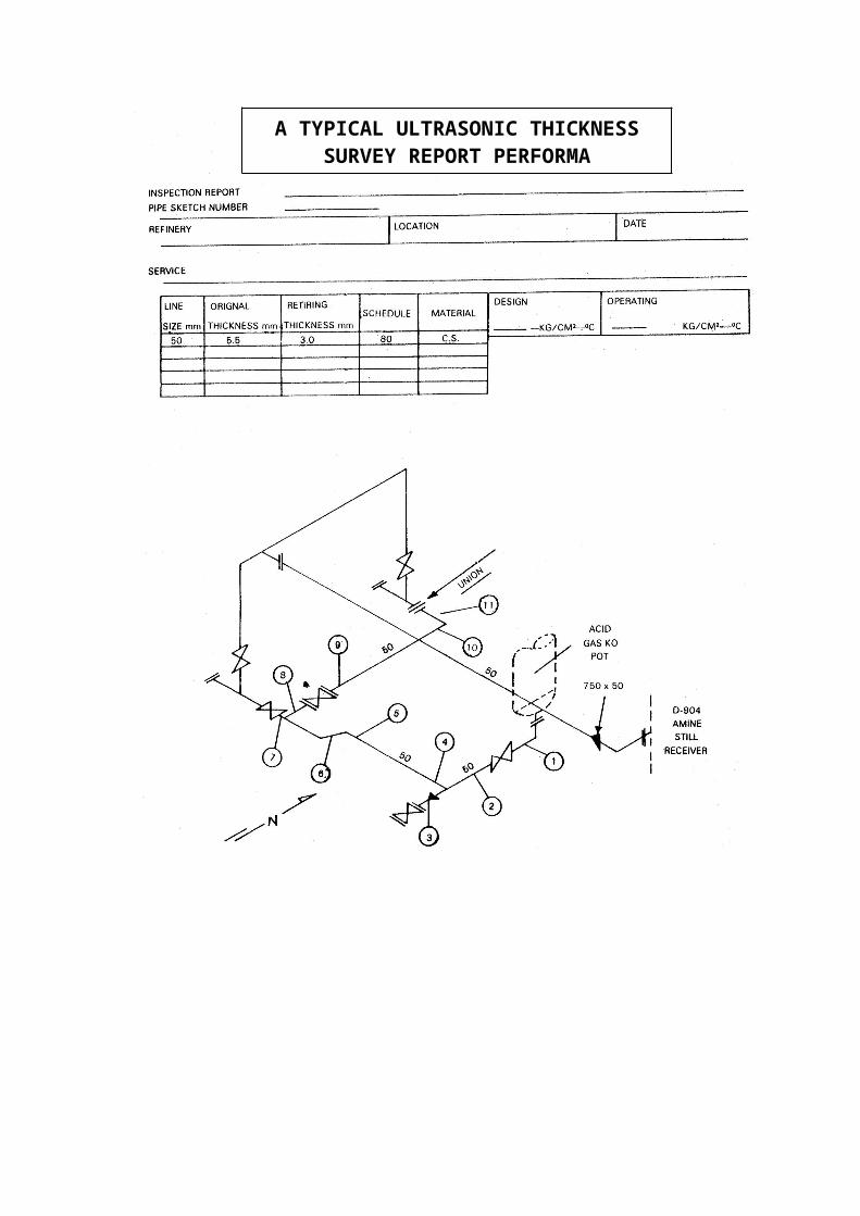
Annexure -XII
Material Verification Program for New and Existing Alloy Piping Systems
A. Introduction
For material and quality assurance system, verification of nominal composition of alloy components with the selected or specified construction material is very important to minimize the potential for catastrophic failure. If the material verification program is not effective at the time of project activities then chances of material mix-up is more, which may lead to failure. This written document is to provide the guidelines for material control and material verification program on ferrous and nonferrous alloys during the construction, installation, maintenance and inspection of new and existing process piping system.
The user should establish a written material verification program indicating the extent and type of Positive material identification (PMI) testing to be conducted during the construction of new piping system or existing piping system and during the maintenance, repair or alteration.
The extent of verification is totally depends on the risk factor involved in that piping like service condition, service fluid, and mode of failure. For higher risk system, the user should consider the need for employing a higher percentage (up to 100%) of examination rather than random sampling, which may be more appropriate for lower risk system.
B. Material Verification Program FOR New Construction
This section covers alloy piping during fabrication either in the shop or in the field prior to the items being placed into service.
In material verification program for new alloy piping system, the following points should be considered:
a. To determine the extent of verification and to verify that the implementation and conduct of the material verification program is properly performed in accordance with recommended practice.
b. To verify that the alloy materials subsequently placed into service are as specified and documentation of the material verification program is in accordance with recommended practice.
c. PMI testing should be performed at that point in time that ensures that proper alloy materials have been used in the fabrication of an identifiable assembly.
d. Mill test report should not be considered a substitute for a PMI test. However, mill test reports are an important part of an overall material quality assurance program.
Following pressure containing components that make up fabricated piping system should be covered in a material verification program:
Pipe lengths Pipe fitting such as tees, elbows, reducers, special pipe components, blinds and plugs. Flanges Special forgings Process valves (including control valves) and relief valves. Pressure containing welds Instruments (all external pressure containing parts). Weld overlays or cladding.
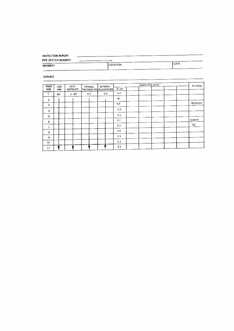
Bolting Expansion joints and bellows
During construction, when welding is conducted, one electrode or wire sample from each lot or package of alloy weld rod should be positively identified. Some weld rods have the alloying elements contained in the flux, and do not meet the alloy specification until welded. PMI testing of weld metal (e.g. deposited weld metal) is an acceptable alternative to PMI testing of an electrode or wire.
When PMI testing is conducted on new or existing piping systems, records of the results should be kept as long as the piping system exists in its original location.
C. Material Verification Program for Existing Piping Systems
This section covers alloy-piping systems that are already in service. In this, it is important to recognize that previous maintenance activities, as well as new construction practices, may influence the probability of inadvertent material substitutions.
If a retroactive material verification program is appropriate for each existing piping system then the user should determine the following, depending on risk factor involved in the system.
Prioritization of piping systems to receive retroactive PMI testing
To determine the extent of PMI testing required.
i) Prioritization piping systems for retroactive PMI testing
If the user elects to prioritize piping systems for the material verification program or needs to determine whether PMI testing is needed at all, the user should consider the following:
Likelihood of material mix-up during previous project and maintenance activities To ensure whether appropriate material is used or not based on frequent failure Inaccurate or missing information regarding existing alloy piping Consequences of failure like toxicity, fire potential, flammability etc. Reason for alloy specification (i.e. corrosion resistance) Historical data relating to inadvertent material substitutions
The user should establish a methodology for estimating the relative priority for PMI testing of various piping circuits within a given unit. This methodology may be based on qualitative or quantitative risk analysis. There are several risk based approaches and the factors that should be considered when conducting a risk analysis such as material, service conditions, service fluid, and mode of failure.
Based on experience, some types of piping system components may have a higher likelihood of inadvertent substitution of a non specified material e.g. carbon steel components in low alloy steel (e.g. 1.25Cr-0.5Mo, 2.25Cr-1Mo, 5Cr-0.5Mo). This could provide a basis for prioritizing specific equipment in a given system or process unit. Examples are:
a. Warm-up and bypass lines on pumps or check valves
b. Small diameter piping systems, including welds, with diameter less than or equal to 2’’ (50mm)
c. Valves and other removable devices
d. Components without an ASTM stamp
e. Thermo wells
f. Bolting
ii) To determine the extent of PMI testing:
Factors to consider when determining the extent of PMI testing for an existing process unit include:
a. Historical inspection and material verification program recordsb. Number of plant modificationsc. Materials control during original construction and during modifications.d. Material verification program quality during construction and fabricatione. Risk analysis of the system.f. Likelihood of corrosion/degradation
D. Material Verification Program Test Methods and It’s Objective:
Objective:
The test methods are intended to identify alloy material and are not intended to establish the exact conformance of a material to a particular alloy specification. The PMI test method may identify the nominal composition of alloy materials.
A description of primary PMI test methods are following:
a. Portable X-ray Fluorescence:
The principle of operation is that one or more gamma ray sources are used to generate a beam of low energy gamma rays to excite the material under analysis. It emits a characteristic spectrum of X rays which may be analyzed both qualitatively and quantitatively to determine which elements are present and in what quantity.
The result of this analysis can be reported in either or both of the following formats:
1. As a match against reference spectra stored in the instrument, i.e. 316ss or 5Cr-1/2Mo steel
2. Each element present is shown as percentage
Elements lighter than sulfur (e.g. Carbon) cannot be detected using this technique because of its limitation.
b. Portable Optical Emission Spectrometry:
An electric arc stimulates atoms in the test sample to emit a characteristic spectrum of light for each element in the sample. The combined light spectra from different elements are passed through a light guide to the optical analyzer. In the analyzer, the light is dispersed into its spectral components, and then measured and evaluated against stored evaluation curves. This technique can typically identify up to 16 elements.
c. Chemical Laboratory Chemical Analysis:
User-approved material analysis laboratories using X-ray emission spectrometry, optical emission spectrometry or wet chemical analysis can provide the most accurate analytical results for all elements.
Other qualitative tests are;
1. Chemical spot testing by removing a minute amount of surface metal
2. Resistivity testing based on Seebeck effect or thermoelectric principle
The following points should be noted:
Before using the test equipment, it should be calibrated. The precision of the test equipment should be consistent with the
established test objectives. The person performing the PMI test should be knowledgeable about all
aspects of operation of PMI test equipment and the PMI test method used.
E. Evaluation of PMI Test Results:
The user may elect any one of the following methods of material acceptance:
a. Material can be confirmed to contain the nominal amounts of alloying elements as per Specification.
b. If PMI testing indicates alloying elements are outside the ranges, then user may still choose to allow the use of the tested materials or not depending on his knowledge.
c. If testing using one of the portable or qualitative analysis methods leads to the potential rejection of a component, a more accurate analysis may be used.
If any one of a representative sample is rejected, all items of that inspection lot should be considered suspect. A more extensive inspection of the remaining lot should considered.
F. Marking and Record Keeping
Alloy materials should be identified by their alloy designation or nominal composition. Examples of some acceptable identification methods are:
a. Color coding by alloyb. A low-stress stamp marking indicating that the test has been performed.c. Documentation showing both the PMI test results and the PMI test locations.
PMI Test Procedures and records:
The PMI test procedure should include the techniques used, equipment calibration elements, the qualification requirements for PMI test Personnel, the testing methodology. Typical PMI test records should contain:
a. Reference to the PMI test procedures used.b. Date of testingc. Test instrument identification number or serial number, whether appropriate.d. Name of each person and company performing the testse. Results of the testf. Basis and action for resolving and documenting PMI test non conformances
including those that have been left in service.g. Documentation of the criteria used for prioritization of piping systems and extent of
PMI testing performed.