inspection of structural health of existing railway ... · pdf filewall 12.1% u-shaped wall...
TRANSCRIPT
2059
Proceedings of the 18th International Conference on Soil Mechanics and Geotechnical Engineering, Paris 2013
1
Inspection of structural health of existing railway retaining walls
Inspection de l’état structurel des murs de soutènement des voies de chemin de fer existantes
S. Nakajima, M. Shinoda & K. AbeRailway Technical Research Institute, Japan
ABSTRACT: This study aims to develop an inspection method of a structural health of the existing retaining walls. This paper beginswith the brief introduction of the current state of the existing retaining structures. Second, applicability of the percussion test for theevaluation of structural health of existing retaining wall is examined by conducting a large numbers of the percussion test on retainingwalls at the site. It was found from the percussion test that structural health of the ashlars wall could be quantitatively evaluated by thepercussion test while it was found to be difficult to apply the percussion test for the quantitative evaluation of the leaning typeretaining wall. Third, applicability of the small scale vibrator, which was newly developed to improve the disadvantage of thepercussion test as the inspection method of the retaining wall, was examined thorough the prototype scale model test on the existingleaning type retaining wall. It was found from the series of model test that the vibration tests were effective in evaluating thecharacteristics of dynamic properties of the retaining walls, which were affected by structural health of the retaining walls. This resultindicated that the small scale vibration tests could be applicable to evaluate the structural health of the existing retaining structures.
RÉSUMÉ : Cette étude vise au développement d’une méthode d’inspection de l’état structurel des murs de soutènement existants.L’article commence par une brève présentation de l’état actuel des structures de soutènement existantes. Il se poursuit par l’expositionde l’analyse de l’applicabilité des essais aux chocs à l’évaluation de l’état structurel des murs de soutènement existants conduits surdes murs de soutènement sur le terrain. Ces essais aux chocs ont montré qu’ils permettaient une évaluation quantitative des murs desoutènement de type en béton mais qu’ils ne se prêtaient guère à l’évaluation des murs de soutènement de type incliné. Une troisièmepartie est consacrée à l’applicabilité d’un vibrateur à faible échelle nouvellement mis au point qui permet de palier les inconvénientsdes essais aux chocs comme méthode d’inspection des murs de soutènement. Un appareil prototype a été utilisé pour l’inspection desmurs de soutènement de type incliné. La série d’essais modèles conduite a mis en évidence que les essais aux vibrations permettaientde bien évaluer les caractéristiques des propriétés dynamiques des murs de soutènement affectés par leur état structurel. Les auteursconcluent que les essais aux vibrations à petite échelle peuvent être appliqués dans l’évaluation de l’état structurel des murs desoutènement existants.
KEYWORDS: Retaining walls, condition rating, small scale exciter, vibration testing
1 BACKGROUND
In Japan, there are many old existing railway structures and itenhances the importance of the proper maintenancemethodology. For the proper management of the railwaystructures, it is important to detect deformations of thestructures in early stage. Once deformations are observed,continuous observations and retrofitting works are alsoimportant. As for the Japanese railway structures, it has alreadydeveloped to evaluate a structural health of bridge piersquantitatively, which makes it possible to maintain structuresefficiently. On the other hand, a visual inspection is still con-ducted to evaluate a structural health of the existing retainingwalls because quantitative inspection method for the existingretaining wall has not yet developed. It is required to evaluate astructural health of the existing retaining walls quantitativelybecause a result of the visual inspection is highly dependent onthe subjective judgment of an inspector.
Based on the background above, this study aims to developan inspection method for the condition rating of the existingretaining walls.
2 CURRENT STATE OF THE RAILWAY RETAININGSTRUCTURE
2.1 Maintenance standards in Japan
There are approximately 30 thousand kilometers of the railwaylines in Japan, which are operated by many railwayorganizations (seven Japan Railway companies, over 100private railway companies and several local governments).
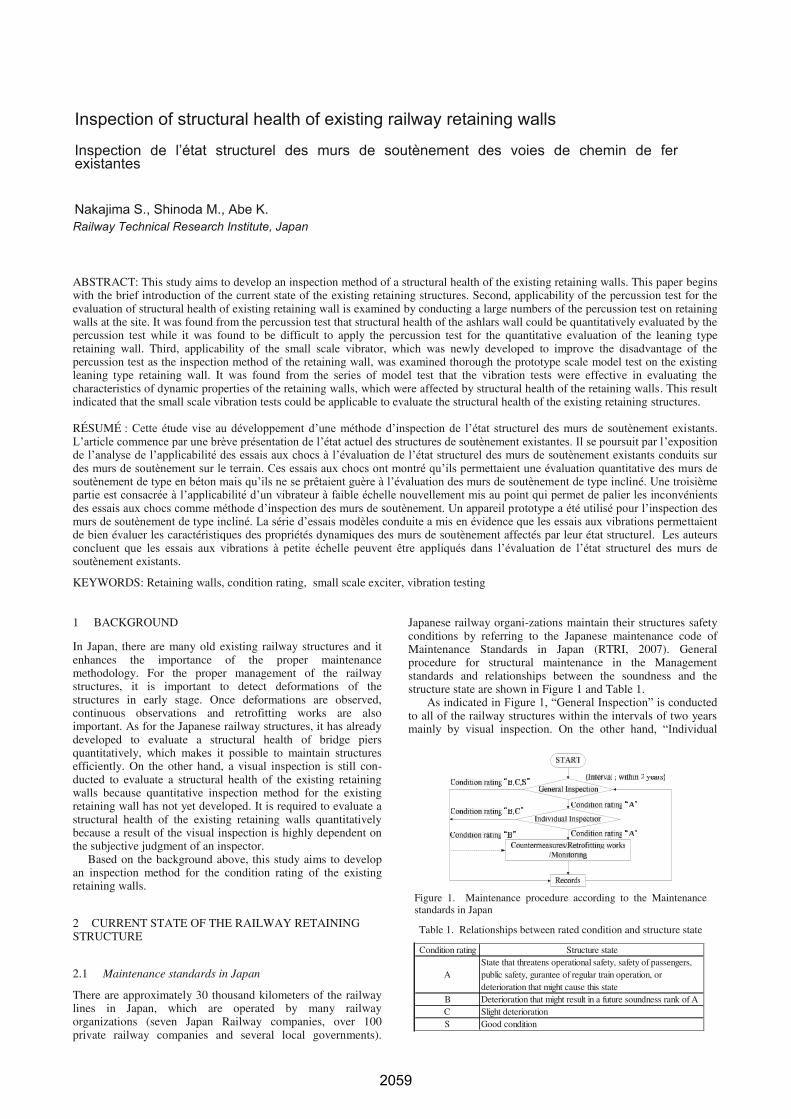
Japanese railway organi-zations maintain their structures safetyconditions by referring to the Japanese maintenance code ofMaintenance Standards in Japan (RTRI, 2007). Generalprocedure for structural maintenance in the Managementstandards and relationships between the soundness and thestructure state are shown in Figure 1 and Table 1.
As indicated in Figure 1, “General Inspection” is conductedto all of the railway structures within the intervals of two yearsmainly by visual inspection. On the other hand, “Individual
Figure 1. Maintenance procedure according to the Maintenancestandards in Japan
Table 1. Relationships between rated condition and structure state
Condition rating Structure state
AState that threatens operational safety, safety of passengers,public safety, gurantee of regular train operation, ordeterioration that might cause this state
B Deterioration that might result in a future soundness rank of AC Slight deteriorationS Good condition
Inspection of structural health of existing railway retaining walls
Inspection de l’état structurel des murs de soutènement des voies de chemin de fer existantes
Nakajima S., Shinoda M., Abe K.
2060
Proceedings of the 18th International Conference on Soil Mechanics and Geotechnical Engineering, Paris 2013
Proceedings of the 18th International Conference on Soil Mechanics and Geotechnical Engineering, Paris 2013
2
Inspection” is performed to the specific structures in whichsevere deterioration are detected at the time of the GeneralInspection by means of detailed visual survey or usingmeasuring equipments. As discussed in BACKGROUND, thisstudy aims to develop a methodology which can be used for thecondition rating of the retaining walls quantitatively as analternative method of detailed visual survey.
2.2 Survey on current state of Japanese railway retainingwalls
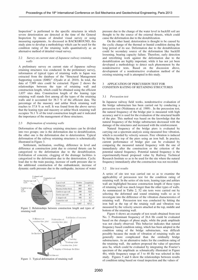
A preliminary survey on current state of Japanese railwayretaining structures was conducted. In the preliminary survey,information of typical types of retaining walls in Japan wasextracted from the database of the “Structural ManagementSupporting system (SMS)” (Oyado et al. 2010). In total, thedata of 7,989 sites could be extracted. Figure 2 shows therelationships between the type of retaining wall andconstruction length, which could be obtained using the efficient1,657 sites data. Construction length of the leaning typeretaining wall stands first among all the types of the retainingwalls and it accounted for 38.3 % of the efficient data. Thepercentage of the masonry and ashlar block retaining wallreaches to 37.8 % as well. It was found from the above surveythat the leaning type and masonry or ashlar block retaining walloccupies 76.1 % of the total construction length and it indicatedthe importance of the management of these structures.
2.3 Deformation of retaining walls
Deformation of the railway retaining structures can be dividedinto two groups; one is the deformation due to destabilization,the other one is the deformation due to deterioration. Typicaldeformation of the railway retaining structures is schematicallyillustrated in Figure 3.
Settlement, inclination, swelling, difference in level anddifference at construction joint due to external thrusts can becategorized to the deformation due to the destabilization.Exfoliation of concrete, clogging of the drainage facilities iscategorized to the deformation due to the deterioration. Cyclicload due to the train passing, increase of earth pressure due tothe additional construction of the embankment, increase ofdynamic earth pressure due to the earthquake, increase of water
pressure due to the change of the water level in backfill soil arethought to be the source of the external thrusts, which couldcause the deformation due to the destabilization.
On the other hand, deterioration is thought to be caused bythe cyclic change of the thermal or humid condition during thelong period of its use. Deformation due to the destabilizationcould be secondary source of the deformation like backfillloosening, bearing capacity failure. Therefore, early detectionand retrofitting work against the deformation due to thedestabilization are highly important, while it has not yet beendeveloped a methodology to detect such phenomenon by thenondestructive tests. Based on the discussion above,development of a nondestructive evaluation method of theexisting retaining wall is attempted in this study.
3 APPLICATION OF PERCUSSION TEST FORCONDITION RATING OF RETAINING STRUCTURES
3.1 Percussion test
In Japanese railway field works, nondestructive evaluation ofthe bridge substructure has been carried out by conducting apercussion test (Nishimura et al. 1989) . In the percussion test,the natural frequency of the bridge pier is measured with highaccuracy and it is used for the evaluation of the structural healthof the pier. This method was based on the knowledge that thenatural frequency of the bridge substructure decreased with thedamage of the structures and increased with the reinforcement.
Natural frequency of the bridge piers is evaluated bycarrying out a spectrum analysis using measured free vibration,which is recorded by velocity sensors. Free vibration is inducedby hitting the top of the piers using an iron ball. In practice,current performance of bridge pier can be evaluated bycomparing the measured natural frequency with the one ofimmediately after the construction or the criterion of thepotential natural frequency. Potential natural frequency is theexperimentally-based proposed value by Railway TechnicalResearch Institute so as to be used for the site where the naturalfrequency immediately after the construction was not recorded.
3.2 Site test results
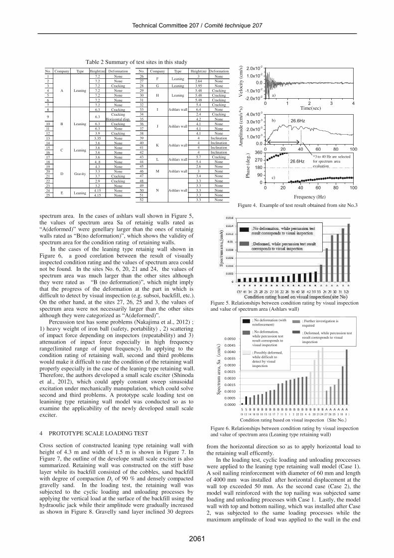
A series of site test was carried out so as to examine theapplicability of percussion test for the condition rating ofretaining wall. In the series of site tests, leaning type and ashlarswall are highlighed because construction length of these typesof retaining wall was much longer than the other types of walls.As summraized in Table 2, 52 site tests were carried out byselecting the deformed and sound retaining walls so as toinvestigate into the difference of the vibration characterestics ofretaining wall. Percussion test was conducted by hitting theiron ball at the top of the retainig wall and vibration wasmeasured by the velocity sencers attached at the top, middle andbottom of the retaining wall.
Figure 4 shows an example of test result obtained from testNo. 3. Predominant frequency of 26.6 Hz could be evaluatedbased on the changes of phase angle, while the peak amplitudewas not clearly observed. This behavior indicates that naturalfrequency based condition rating, which has been adopted in thecondition rating of the bridge substructure, was difficultpossibly because the mode of vibration of retaining walls aregenerally more complicated than the oridinally bridgesubstructures. As an alternative index for the condition rating ofthe retaining wall, the authors proposed the value of spectrumarea Sa, which could be evaluated by integrating the Fourier’sspectrum of the amplitude as schmatically illustrated in Figure4b), while frequency range of 3 to 40 Hz was selected in thisstudy. Figures 5 and 6 show the relationships between resultsof condition rating based on visual inspection and the values of
MasonryAshlar block wall37.8%
Leaning typewall38.3%
Gravity type wall6.2%
Cantilever typewall12.1%
U-shaped wall5.3% Counterfort wall
0.2%
Masonry/Ashlar block
Leaning type
Gravity type wall
Cantilevet type wall
U-shaped wall
Counterfort wall
Type of wall Number
409
802
249
85
7
105
Total 1,657
Length(km)
41.1
40.6
13.0
6.7
5.7
0.2
107.3
Figure 2. Relationships between construction length and types ofretaining wall
D ifference at
construction joint
C onstruction Joint
C racking
D rainage pipe
C logging of drainage facilities
Exfoliation of concrete
Settlem ent
Inclination
D islocation at
construction joint
Figure 3. Typical deformation of retaining wall
2061
Technical Committee 207 / Comité technique 207
Proceedings of the 18th International Conference on Soil Mechanics and Geotechnical Engineering, Paris 2013
3
spectrum area. In the cases of ashlars wall shown in Figure 5,the values of spectrum area Sa of retainig walls rated as“A(deformed)” were genellary larger than the ones of retainigwalls rated as “B(no deformation)”, which shows the validity ofspectrum area for the condition rating of retaining walls.
In the cases of the leaning type retainig wall shown inFigure 6, a good corelation between the result of visuallyinspected condition rating and the values of spectrum area couldnot be found. In the sites No. 6, 20, 21 and 24, the values ofspectrum area was much larger than the other sites althoughthey were rated as “B (no deformation)”, which might implythat the progress of the deformation at the part in which isdifficult to detect by visual inspection (e.g. subsoi, backfill, etc.).On the other hand, at the sites 27, 26, 25 and 3, the values ofspectrum area were not necessarily larger than the other sitesalthough they were categorized as “A(deformed)”.
Percussion test has some problems (Nakajima et al., 2012) ;1) heavy weight of iron ball (safety, portability) , 2) scatteringof impact force depending on inspectors (repeatability) and 3)attenuation of inpact force especially in high frequencyrange(limited range of input frequency). In applying to thecondition rating of retaining wall, second and third problemswould make it difficult to rate the condition of the retaining wallproperly especially in the case of the leaning type retaining wall.Therefore, the authors developed a small scale exciter (Shinodaet al., 2012), which could apply constant sweep sinusoidalexcitation under mechanically manupulation, which could solvesecond and third problems. A prototype scale loading test onleanining type retaining wall model was conducted so as toexamine the applicability of the newly developed small scaleexciter.
4 PROTOTYPE SCALE LOADING TEST
Cross section of constructed leaning type retaining wall withheight of 4.3 m and width of 1.5 m is shown in Figure 7. InFigure 7, the outline of the develope small scale exciter is alsosummarized. Retaining wall was constructed on the stiff baselayer while its backfill consisted of the cobbles, sand backfillwith degree of compaction Dc of 90 % and densely compactedgravelly sand. In the loading test, the retaining wall wassubjected to the cyclic loading and unloading processes byapplying the vertical load at the surface of the backfill using thehydraoulic jack while their amplitude were gradually increasedas shown in Figure 8. Gravelly sand layer inclined 30 degrees
from the horizontal direction so as to apply horizontal load tothe retaining wall efficently.
In the loading test, cyclic loading and unloading proccesseswere applied to the leaning type retaining wall model (Case 1).A soil nailing reinforcement with diameter of 60 mm and lengthof 4000 mm was installed after horizontal displacement at thewall top exceeded 50 mm. As the second case (Case 2), themodel wall reinforced with the top nailing was subjected sameloading and unloading processes with Case 1. Lastly, the modelwall with top and bottom nailing, which was installed after Case2, was subjected to the same loading processes while themaximum amplitude of load was applied to the wall in the end
Table 2 Summary of test sites in this studyNo. Company Type Height(m) Deformation
1
A Leaning
7.2 None2 7.2 None3 7.2 Cracking4 7.2 None5 7.2 None6 7.2 None7 7.2 None8
B Leaning
6.3 Cracking
9 6.3Cracking
Horizontal disp.10 6.3 Cracking11 6.3 None12 3.9 Cracking13 3.35 None14
C Leaning
3.6 None15 3.6 None16 3.6 None17 3.6 None18
D Gravity
4..8 None19 4.3 None20 3.3 None21 3.7 Cracking22 2.9 Cracking23 3.2 None24
E Leaning4.15 None
25 4.15 None
No. Company Type Height(m) Deformation26
F Leaning3 None
27 2.64 None28 G Leaning 3.95 None29
H Leaning5.48 Cracking
30 5.48 Cracking31 5.48 Cracking32
I Ashlars wall5.4 Cracking
33 6.4 None34 2.4 Cracking35
J Ashlars wall
4.2 None36 4.1 None37 4.1 None38 4.1 None39
K Ashlars wall
4 Inclination40 4 Inclination41 4 Inclination42 4 Inclination43
L Ashlars wall5.7 Cracking
44 5.4 None45
M Ashlars wall2.6 None
46 3 None47 3.4 None48
N Ashlars wall
3.3 None49 3.3 None50 3.3 None51 3.3 None52 3.3 None
0 20 40 60 80 1000.0
1.0x10⁻³
2.0x10⁻³
3.0x10⁻³
4.0x10⁻³
上部(ch1)26.6Hz
振幅
(cm/s*s)
振動数(H z)
0 20 40 60 80 1000
90
180
270
360 上部(ch1)
位相
(度
)
振動数(H z)
26.6Hz
a)
Frequency (Hz)
Time(sec)
b)
c)Phas
e (d
eg.)
Am
plit
ude
(cm
/s*s
)
0 1 2 3 4-2.0x10⁻²
-1.0x10⁻²
0.01.0x10-2
2.0x10⁻²
上部(ch1)
時間(s)
速度
(cm/s)
Vel
ocit
y (c
m/s
)
*3 to 40 Hz are selectedfor spectrum areaevaluation
Figure 4. Example of test result obtained from site No.3
Figure 5. Relationships between condition rating by visual inspectionand value of spectrum area (Ashlars wall)
Condition rating based on visual inspection(Site No.)
Spec
trum
are
a, S
a (cm
/s)
(9 12 14 16 19 18 15 13 17 7 11 5 1 2 22 23 4 6 20 21 24 27 26 25 3 10 8 )
0.0000
0.0005
0.0010
0.0015
0.0020
0.0025
0.0030
0.0035
0.0040
0.0045
0.0050
S S B B B B B B B B B B B B B B B B B B B A A A A A A
; No deformation (withreinforcement)
; No deformation,while percussion testresult corresponds tovisual inspection
; Possibly deformed,while difficult todetect by visualinspection
; Deformed, while percussion testresult corresponds to visualinspection
; Further investigation isrequired
Figure 6. Relationships between condition rating by visual inspectionand value of spectrum area (Leaning type retaining wall)
2062
Proceedings of the 18th International Conference on Soil Mechanics and Geotechnical Engineering, Paris 2013
Proceedings of the 18th International Conference on Soil Mechanics and Geotechnical Engineering, Paris 2013
4
of loading process (Case 3). The loading and unloadingprocesses in each case were summarized in Figure 8.
At every loading and unloading process, sets of percussiontest with a set of velocity sencers and vibration tests using thedeveloped small scale exciter with a set of accelerometers wereconducted so as to investigate into the difference of vibrationcharacterestics obtained from each test. Vibration test wasconducted by applying the sinusoidal sweep excitation to theretaining wall model by the small scale exciter fixed at the topof the retaining wall, while the constant amplitude of 1000 galswith frequency range of 3 to 100 Hz and sweeping rate of 3Hz/sec were adopted as the test condition.
Figure 8 also shows load-displacement relationships obtaiedfrom the loadcell installed at the hydraulic jack anddisplacement transducer at the top of the retaining wall. Asclearly shown in Figure 8, the increment of the wall topdisplacement was drastically reduced by adding the soil nailingalthough the same amplitude of loading processes were appliedto the wall. Displacement increment during a set of loading andunloading processes in Cases 1, 2 and 3 were 50mm, 1.0mmand 0.5 mm respectively.
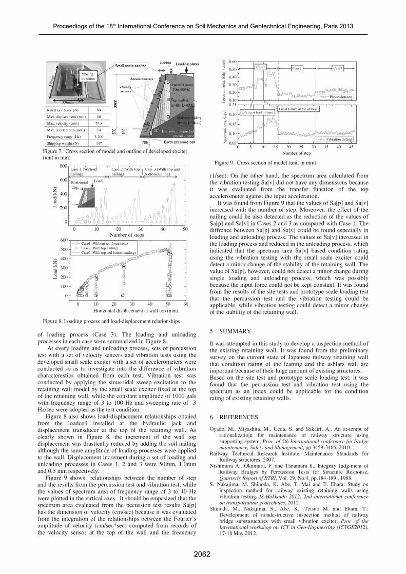
Figure 9 shows relationships between the number of stepand the results from the percussion test and vibration test, whilethe values of spectrum area of frequency range of 3 to 40 Hzwere plotted in the virtical axes. It should be empasized that thespectrum area evaluated from the pecussion test results Sa[p]has the dimension of velocity (cm/sec) because it was evaluatedfrom the integration of the relationships between the Fourier’samplitude of velocity (cm/sec*sec) computed from records ofthe velocity sensor at the top of the wall and the freauency
(1/sec). On the other hand, the spectrum area calculated fromthe vibration testing Sa[v] did not have any dimensions becauseit was evaluated from the transfer function of the topaccelerometer against the input acceleration.
It was found from Figure 9 that the values of Sa[p] and Sa[v]increased with the number of step. Moreover, the effect of thenailing could be also detected as the reduction of the values ofSa[p] and Sa[v] in Cases 2 and 3 as compared with Case 1. Thediffrence between Sa[p] and Sa[v] could be found especially inloading and unloading process. The values of Sa[v] increased inthe loading process and reduced in the unloading process, whichindicated that the spectram area Sa[v] based condition ratingusing the vibration testing with the small scale exciter coulddetect a minor change of the stability of the retaining wall. Thevalue of Sa[p], however, could not detect a minor change duringsingle loading and unloading process, which was possiblybecause the input force could not be kept constant. It was foundfrom the results of the site tests and prototype scale loading testthat the percussion test and the vibration testing could beapplicable, while vibration testing could detect a minor changeof the stability of the retaining wall.
5 SUMMARY
It was attempted in this study to develop a inspection method ofthe existing retaining wall. It was found from the preliminarysurvey on the current state of Japanese railway retaining wallthat condition rating of the leaning and the ashlars wall areimportant because of their huge amount of existing structures.Based on the site test and prototype scale loading test, it wasfound that the percussion test and vibration test using thespectrum as an index could be applicable for the conditionrating of existing retaining walls.
6 REFERENCES
Oyado, M., Miyashita, M., Ueda, S. and Sakairi, A., An at-tempt ofrationalizatiojn for maintenance of railway structure usingsupporting system, Proc. of 5th International conference for bridgemaintenance, Safety and Management, pp.3459-3466, 2010.
Railway Technical Research Institute, Maintenance Standards forRailway structures, 2007.
Nishimura A., Okumura, F. and Tanamura S., Integrity Judg-ment ofRailway Bridges by Percussion Tests for Structure Response,Quarterly Report of RTRI, Vol. 29, No.4, pp.184-189., 1988.
S. Nakajima, M. Shinoda, K. Abe, T. Mai and T. Ehara: Study oninspection method for railway existing retaining walls usingvibration testing, IS-Hokkaido 2012: 2nd international conferenceon transportation geotechnics, 2012.
Shinoda, M., Nakajima, S., Abe, K., Tetsuo M. and Ehara, T.:Development of nondestructive inspection method of railwaybridge substuructures with small vibration exciter, Proc of theInternational workshop on ICT in Geo-Engineering (ICTGE2012),17-18 May 2012.
0.10
0.20
0.30
0.40
0.50
0.60
0 5 10 15 20 25 30 35 40 450.05
0.10
0.15
0.20
0.25
Percussion test
Spec
trum
are
a, S
a[p]
(cm
/s)
Vibration testing
Number of step
Spec
trum
are
a, S
a[v]
Case2 Case3Case1
Lift up at heel of baseLocal failure at toe of base
Figure 9. Cross section of model (unit in mm)
336mm
Movingdirection
Rated sine force (N) 98
Max. displacement (mm) 80
Max. velocity (cm/s) 74.8
Max. acceleration (m/s2) 14
Frequency range (Hz) 3-200
Shipping weight (N) 147
Figure 7. Cross section of model and outline of developed exciter(unit in mm)
0 10 20 30 40 50
0
200
400
600
800
Loa
d(kN
)
Number of steps
LoadHorizontaldisp.
Case 1 (Withoutnailing)
Case 2 (With topnailing)
Case 3 (With top andbottom nailing)
0 10 20 30 40 50 60
0
100
200
300
400
500
600
Loa
d(kN
)
Horizontal displacement at wall top (mm)
Case1 (Without reinforcement) Case2 (With top nailing) Case3 (With top and bottom nailing)
Figure 8. Loading process and load-displacement relationships