inst hsc 10-17 - downloads.halfen.com · betonier-abschnitt 2 betonier-abschnitt 1 monolithische...
TRANSCRIPT

HALFEN HSC INST_HSC 10/17
Stud Connector
D
PL Zbrojenie krótkich wsporników
Armature pour corbeauF
Stud Connector
GB
Assembly Instructions • Montageanleitung • Notice d‘utilisation • Instrukcja montażu

2 © 2017 HALFEN · INST_HSC 10/17 · www.halfen.com
HALFEN HSC Assembly instructions D
euts
chEn
glis
hFr
ança
isPo
lski
H
D
□ 75 mm
h = 9 mm
H
D
HSC20
S∅20
xyy
Concreting step 2
Concreting step 2
Concreting step 1
Monolithic solution
Magnetic plate Nailing plate, metalNailing plate, plastic
The thread of the HSC Socket bars must be covered and protected with a sealing cap.
Stud heads Sleeves
HSC-S, HSC-SD
Single headed, female bar
Single headed, male bar
Double female bar Double headed bar Single headed bar
HSC-S HSC-A HSC-SD HSC-HD HSC-H
Manufacturer’s mark
Product, bar diameter dHSC
Formwork accessories
Installation examples
Product overview
Identifi cation
HSC-HD
Multi-phase concreting solutions
HSC-A HSC-AHSC-SDNailing plate
Variant 2: simplifi ed key joint
Variant 1: Interlocking joint in accor-dance with DIN EN 1992-1-1
Pos : Construction bar for stirrups
Female and male bars
Bar diameter ds 12 16 20 25
Thread M12 x 1.75 * M16 x 2 * M20 x 2,5 * M25 x 2,5
Colour;
protection pluggreen orange light blue brown
* = ISO standard metric screw thread (DIN 13-1)
12 - 16 - 20 - 25

3© 2017 HALFEN · INST_HSC 10/17 · www.halfen.com
HALFEN HSC Assembly instructions
Deu
tsch
Engl
ish
Fran
çais
Pols
ki
Attached to existing reinforcement, e. g. by wire fi xing!
Min. distances to ensure installation (male bars)
dHSC [mm] eHSC [mm] aHSC [mm]12 10 1516 20 2020 20 2525 25 30
Stud heads can be aligned horizontal-ly or vertically. To ensure installation of the (male) connecting bars, mini-mum spacing has to be maintained (not necessary for monolithic compo-nents). The engineer’s specifi cations are obligatory.
eHSC
dHSC
Variation 1: anchor-heads aligned in one plane
dHSC
aHSCVariation 2: staggered HSC anchors – minimized axial distances
Vertical anchor-head placement Horizontal anchor-head placement
Mounting positions
The concrete cover specifi ed in the drawing must also be maintained for the stud heads.
Anchorage in columns: The stud-heads are positioned behind the rear longitudinal column reinforcement.
Welding, even spot welding, can impair material properties. For that reason welding and heat application in the head and thread area is not allowed. Other welding, outside of this area has to be carried out according to applicable welding regulations and is the sole responsibility of the welding-contractor.
(Concrete cover)c
i
The engineers specifi cations (installation position, concrete cover etc.) have to be observed.

4 © 2017 HALFEN · INST_HSC 10/17 · www.halfen.com
HALFEN HSC Assembly instructions D
euts
chEn
glis
hFr
ança
isPo
lski
ds 25 mm
ds 12-16-20 mm
ds 12-16-20 mm
ds 12-16-20 mm ds 12-16-20 mm
ds 12-16-20 mm Framework (batten) for simplifi ed keyed joint
ds
Fixing with hex head bolt with ISO thread:M12 for ds 12, M16 for ds 16, M20 for ds 20
Magnetic plate
Nailing plate, steel
ds
ds
ds
Interlocking joint; no batten in nailing plate position.
ds
Nailing plate, plastic
Screw-depth: The HSC (male) connecting bar is turned into the sleeve until the thread is no longer visible. The bar is then rotated until the anchor head is correctly aligned (horizontal or vertical).
Thread detail of a HSC Connection
ds
HSC Connecting BarHSC female bar
1st concreting phase 2nd concreting phase
ds
Fixing to timber formwork
Installing the connecting bars (male)
Fixing to steel formwork
Refer to the engineer’s specifi cations. Subsequent bending in the thread is not permitted. Secure elements properly during shipping to avoid movement in construction joints.

5© 2017 HALFEN · INST_HSC 10/17 · www.halfen.com
HALFEN HSC Montageanleitung
Deu
tsch
Engl
ish
Fran
çais
Pols
ki
H
D
□ 75 mm
h = 9 mm
H
D
HSC20
S∅20
xyy
Betonier-abschnitt 2
Betonier-abschnitt 2
Betonier-abschnitt 1
Monolithische Ausführung
Magnetteller Metall-NagelplatteKunststoff nagelteller
Das Einschraubgewinde der HSC- Muff enstäbe muss mit einer Gewinde-verschlussschraube verschlossen sein.
Ankerköpfe Muff en
HSC-S, HSC-SD
Muff enstab Anschlussstab Doppelmuff enstab Ankerkopf beidseitig Ankerkopf einseitig
HSC-S HSC-A HSC-SD HSC-HD HSC-H
Werkskennzeichnung
Schalungszubehör
Montagebeispiele
Produktübersicht
Kennzeichnung
HSC-HD
Ausführung in Betonierabschnitten
HSC-A HSC-AHSC-SDNagelteller
Variante 2: Schubzahn
Variante 1: Verzahnte Fuge nach DIN EN 1992-1-1
Pos : Lagesicherung für Bügel
Muffen- und Anschlussstäbe
Stabdurchmesser ds 12 16 20 25
Gewinde M12 x 1.75 * M16 x 2 * M20 x 2,5 * M25 x 2,5
Kennfarbe grün orange hellblau braun
* = ISO metrisches Standardgewinde (DIN 13-1)
12 - 16 - 20 - 25
Produkt, Stabdurchmesser dHSC
6 © 2017 HALFEN · INST_HSC 10/17 · www.halfen.com
HALFEN HSC Montageanleitung D
euts
chEn
glis
hFr
ança
isPo
lski
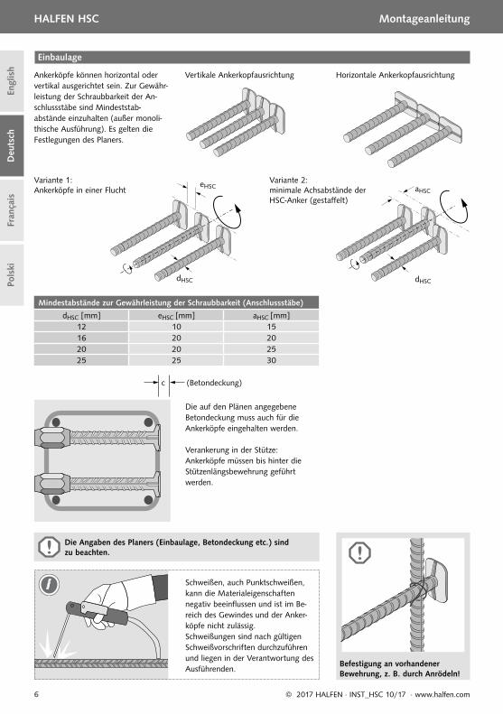
Mindestabstände zur Gewährleistung der Schraubbarkeit (Anschlussstäbe)
dHSC [mm] eHSC [mm] aHSC [mm]12 10 1516 20 2020 20 2525 25 30
eHSC
dHSC
Ankerköpfe können horizontal oder vertikal ausgerichtet sein. Zur Gewähr-leistung der Schraubbarkeit der An-schlussstäbe sind Mindeststab-abstände einzuhalten (außer monoli-thische Ausführung). Es gelten die Festlegungen des Planers.
Variante 1: Ankerköpfe in einer Flucht
dHSC
aHSC
Variante 2: minimale Achsabstände der HSC-Anker (gestaff elt)
Vertikale Ankerkopfausrichtung Horizontale Ankerkopfausrichtung
Einbaulage
Befestigung an vorhandener Bewehrung, z. B. durch Anrödeln!
Die auf den Plänen angegebene Betondeckung muss auch für die Ankerköpfe eingehalten werden.
Verankerung in der Stütze: Ankerköpfe müssen bis hinter die Stützenlängsbewehrung geführtwerden.
Schweißen, auch Punktschweißen, kann die Materialeigenschaften negativ beeinfl ussen und ist im Be-reich des Gewindes und der Anker-köpfe nicht zulässig. Schweißungen sind nach gültigen Schweißvorschriften durchzuführen und liegen in der Verantwortung des Ausführenden.
(Betondeckung)c
i
Die Angaben des Planers (Einbaulage, Betondeckung etc.) sind zu beachten.

7© 2017 HALFEN · INST_HSC 10/17 · www.halfen.com
HALFEN HSC Montageanleitung
Deu
tsch
Engl
ish
Fran
çais
Pols
ki
ds 25 mm
ds 12-16-20 mm
ds 12-16-20 mm
ds 12-16-20 mm ds 12-16-20 mm
ds 12-16-20 mm Schalbrett für Schubzahn
ds
Befestigung mit Sechskantschraube ISO Regelgewinde:M12 bei ds 12, M16 bei ds 16, M20 bei ds 20
Magnetteller
Nagelteller, Stahl
ds
ds
ds
Leiste für verzahnte Fugenausbildung.Im Bereich des Nagel-tellers ausgespart
ds
Nagelteller, Kunststoff
Einschraubtiefe: Der HSC-Anschlussstab wird einge-schraubt, bis das gesamte Gewinde von der Schraubmuff e verdeckt ist. Danach darf der Stab noch gedreht werden, bis der Ankerkopf die richtige Orientierung (horizontal/
Schnitt durch einen HSC-Anschluss
ds
HSC AnschlussstabHSC Muff enstab
1. Betonierabschnitt 2. Betonierabschnitt
ds
Befestigung an der Holzschalung
Einschrauben der Anschlussstäbe
Befestigung an Stahlschalung
vertikal) angenommen hat. Die Angaben des Planers sind zu beachten. Das Nachbiegen der Stäbe im Gewindebereich ist nicht zulässig. Ein Klaff en der Betonierfuge während des Transportes ist zu verhindern.

8 © 2017 HALFEN · INST_HSC 10/17 · www.halfen.com
Deu
tsch
Engl
ish
Fran
çais
Pols
kiHALFEN HSC Notice d‘utilisation
H
D
□ 75 mm
h = 9 mm
H
D
HSC20
S∅20
xyy
Bétonnage phase 2
Bétonnage phase 2
Bétonnage phase 1
Solution avec corbeau monolithique
Fixation magnétique Fixation en acier à clouerFixation en plastique à clouer
Les armatures HSC avec douille femelle sont livrées avec un bouchon de protection monté dans les usines HALFEN
Pied d‘ancrage Manchons
HSC-S, HSC-SD
Armature à pied d‘ancrage unique et à douille femelle
Armature à pied d‘ancrage unique et fi letage mâle
Armature à double douille femelle
Armature à double pied d‘ancrage
Armature à pied d‘ancrage simple
HSC-S HSC-A HSC-SD HSC-HD HSC-H
Fabricant
Accessoires de coff rage
Exemples d‘utilisation
Aperçu des produits
Identifi cation
HSC-HD
Solution avec corbeau rapporté
HSC-A HSC-AHSC-SDFixation à clouer
Variante 2: joint simplifi éVariante 1: Joint cranté suivant laDIN EN 1992-1-1
: Maintenir les étriers en position
Armatures mâles et manchons femelles
Diamètre de barre ds 12 16 20 25
Diamètre de la barre M12 x 1.75 * M16 x 2 * M20 x 2,5 * M25 x 2,5
Couleur du bouchon de protection vert orange bleu clair marron
* = Filetage à pas métrique standard (ISO)
12 - 16 - 20 - 25
Type, diamètre barre dHSC

9© 2017 HALFEN · INST_HSC 10/17 · www.halfen.com
Deu
tsch
Engl
ish
Fran
çais
Pols
ki
HALFEN HSC Notice d‘utilisation
Entraxe minimum entre les pieds d‘ancrage (ancres verticales)
dHSC [mm] eHSC [mm] aHSC [mm]
12 10 1516 20 2020 20 2525 25 30
Les pieds des armatures HSC peuvent êtres placés indiff éremment dans le sens vertical ou horizontal suivant les recommandations du bureau d’étude.
Variante 1: Pieds d‘ancrage alignés sur un même plan
Variante 2: Pieds d‘ancrage positionnés sur deux plans diff érents
Pied d‘ancrage vertical Pied d‘ancrage horizontal
Disposition
eHSC
dHSCdHSC
aHSC
L‘armature HSC à double pied d‘ancrage peut être fi xée au ferrail-lage vertical du poteau, par exemple avec des fi ls à ligaturer!
L’enrobage du béton (c) stipulé dans les schémas doit être également re-specté à l’arrière du pied.
Le pied des armatures doit être positionné derrière les aciers verticaux du poteau.
La soudure, même par points, peut altérer les propriétés du matériau. Pour cette rai-son, il n’est pas autorisé de souder ou d’appliquer toute source de chaleur sur le pied d’ancrage. En dehors du pied d’ancrage, toute soudure doit être eff ectuée conformément aux réglementations en vi-gueurs et suivant les recommandations de l’armaturier ou du soudeur.
(Enrobage)c
i
Les recommandations du bureau d‘étude du projet doivent être respectées (positionnement, enrobage de béton etc.).
10 © 2017 HALFEN · INST_HSC 10/17 · www.halfen.com
Deu
tsch
Engl
ish
Fran
çais
Pols
kiHALFEN HSC Notice d‘utilisation
ds 25 mm
ds 12-16-20 mm
ds 12-16-20 mm
ds 12-16-20 mm ds 12-16-20 mm
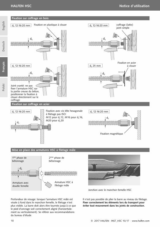
ds 12-16-20 mm coffrage (latte)joint simple
ds
Fixation avec vis tête hexagonale à fi letage pas ISO:M12 pour ds 12, M16 pour ds 16, M20 pour ds 20
Fixation magnétique
Fixation en acier à clouer
ds
ds
ds
Joint cranté: ne pas fi xer l‘armature HSC sur la partie creuse du béton, positionner la fi xation à clouer directement sur le coff rage
ds
Fixation en plastique à clouer
Profondeur de vissage: lorsque l‘armature HSC mâle est vissée à fond dans le manchon femelle, le fi letage n‘est plus visible. La barre doit alors être tournée jusqu‘à ce que le pied d‘ancrage soit correctement aligné (horizontale-ment ou verticalement). Se référer aux recommandations du bureau d‘étude.
Jonction avec le manchon femelle HSC
ds
Armature HSC à fi letage mâle
Armature avec douille femelle
1ère phase de bétonnage
2ème phase de bétonnage
ds
Fixation sur coff rage en bois
Mise en place des armatures HSC à fi letage mâle
Fixation sur coff rage en acier
Il n‘est pas possible de plier la barre au niveau du fi letage. Fixer correctement les éléments lors du transport pour éviter tout mouvement dans les joints de construction.

11© 2017 HALFEN · INST_HSC 10/17 · www.halfen.com
HALFEN HSC Instrukcja montażu
Deu
tsch
Engl
ish
Fran
çais
Pols
ki
H
D
□ 75 mm
h = 9 mm
H
D
HSC20
S∅20
xyy
Etap 2 betonowania
Etap 2 betonowania
Etap 1 betonowania
Połączenie monolityczne
Krążek montażowy magnetyczny Płytka montażowa przybijanaKrążek montażowy przybijany
Gwint wewnętrzny tulei musi być zabezpieczony śrubą uszczelniającą.
Główka trzpienia Tuleja gwintowana
HSC-S, HSC-SD
Trzpień z tulejągwintowaną
Trzpień zakończony gwintem
Trzpień zakończonytulejkami
Trzpień zakończonygłówkami
Trzpień zakończonygłówką
HSC-S HSC-A HSC-SD HSC-HD HSC-H
Symbol zakładu produkcyjnego
Asortyment do szalowania
Przykłady zastosowań
Przegląd produktów
Oznaczenie
HSC-HD
Połączenie wrębowe
HSC-A HSC-AHSC-SD
Krążek montażowy
Wariant 2: Połączeniena wrąb
Wariant 1: Połączenie z wrębami DIN EN 1992-1-1
Pos : Stabilizacja położenia strzemion
Trzpienie gwintowane i z tulejami
Średnica pręta ds 12 16 20 25
Gwint M12 x 1.75 * M16 x 2 * M20 x 2,5 * M25 x 2,5
Kolor zatyczek gwintów Zielony Pomarańcz Niebieski Brązowy
* = Gwinty metryczne ISO (DIN 13-1)
12 - 16 - 20 - 25
Produkt, średnica pręta dHSC

12 © 2017 HALFEN · INST_HSC 10/17 · www.halfen.com
HALFEN HSC Instrukcja montażu D
euts
chEn
glis
hFr
ança
isPo
lski
Minimalne odstępy trzpieni gwintowanych zapewniające ich montaż
dHSC [mm] eHSC [mm] aHSC [mm]12 10 1516 20 2020 20 2525 25 30
Główki trzpieni można układać piono-wo lub poziomo. W celu zapewnienia montażu trzpieni gwintowanych,należy przestrzegać minimalnych rozstawów trzpieni (nie dotyczy połączeń monolitycznych). Obowiązują ustalenia projektanta.
Wariant 1: Główki trzpieni w jednej płaszczyźnie
Wariant 2: Główki przemiennie w dwóch płaszczyznach
Pionowe ułożenie główek trzpieni Poziome ułożenie główek trzpieni
Ułożenie zbrojenia
eHSC
dHSC dHSC
aHSC
Mocowanie do istniejącegozbrojenia drutem wiązałkowym!
Projektowana otulina betonowa musi być także zachowana dla główek trzpieni. Zakotwienie w słupie: główki trzpieni muszą zachodzić za zbrojenie podłużne słupa.
Spawanie, także punktowe, może negatywnie wpływać na właściwości materiału, dlatego w obszarze gwin-tu oraz główki jest zabronione. Spawanie poza wymienionymi obsza-rami wykonuje się zgodnie z aktualnymi przepisami i wiedzą techniczną, na odpowiedzialność wykonującego.
(otulina betonowa)c
i
Należy przestrzegać wytycznych projektowych (rozmieszczenie zbrojenia, otulina betonowa, itd.).

13© 2017 HALFEN · INST_HSC 10/17 · www.halfen.com
HALFEN HSC Instrukcja montażu
Deu
tsch
Engl
ish
Fran
çais
Pols
ki
ds 25 mm
ds 12-16-20 mm
ds 12-16-20 mm
ds 12-16-20 mm ds 12-16-20 mm
ds 12-16-20 mm Deskowanie połączenia na wrąb
ds
Mocowanie za pomocą sześciokątnej śruby metrycznej:M12 dla ds 12, M16 dla ds 16, M20 dla ds 20
Magnetyczny krążek montażowy
Płytka montażowa, stalowa
ds
ds
ds
Wywiercić otwór w listwie dla umieszczenia krążka montażowego.
ds
Przybijany krążek montażowy z tworzywa.
Głębokość wkręcenia: gwintowany trzpień HSC wkręcać do momentu całkowitego schowania się gwintu w tulei.Następnie (jeżeli wymagane) obrócić trzpień, celem prawidłowego położenia główki trzpienia (pionowego lub
Przekrój skręconego połączenia
ds
HSC z końcem gwintowanym
HSC z tuleją
1 etap betonowania 2 etap betonowania
ds
Mocowanie do szalunku drewnianego
Montaż trzpieni gwintowanych
Mocowanie do szalunku stalowego
poziomego), zgodnie z danymi projektowymi. Doginanie pręta w strefi e gwintu zabronione. Złącze wrębowe należy zabezpieczyć na czas transportu.

14 © 2017 HALFEN · INST_HSC 10/17 · www.halfen.com
HALFEN HSC D
euts
chEn
glis
hFr
ança
isPo
lski

NOTES REGARDING THIS DOCUMENTTechnical and design changes reserved. The information in this publication is based on state-of-the-art technology at the time of publication. We reserve the right to make technical and design changes at any time. HALFEN GmbH shall not accept liability for the accuracy of the information in this publication or for any printing errors.
The HALFEN GmbH subsidiaries in Germany, France, the Nether-lands, Austria, Poland, Switzerland and the Czech Republic are Quality Management certifi ed according to ISO 9001:2015, Certifi cate no. 202384-2016-AQ-GER-DAkkS.
Furthermore HALFEN is represented with sales offi ces and distributors worldwide.
Austria HALFEN Gesellschaft m.b.H.Leonard-Bernstein-Str. 101220 Wien
Phone: +43 - 1 - 259 6770 E-Mail: offi [email protected]: www.halfen.at
Fax: +43 - 1 - 259 - 6770 99
Belgium /Luxembourg
HALFEN N.V.Borkelstraat 1312900 Schoten
Phone: +32 - 3 - 658 07 20E-Mail: [email protected]: www.halfen.be
Fax: +32 - 3 - 658 15 33
China HALFEN Construction Accessories Distribution Co.Ltd.Room 601 Tower D, Vantone CentreNo.A6 Chao Yang Men Wai StreetChaoyang District Beijing · P.R. China 100020
Phone: +86 - 10 5907 3200E-Mail: [email protected]: www.halfen.cn
Fax: +86 - 10 5907 3218
Czech Republic HALFEN s.r.o.Business Center ŠafránkovaŠafránkova 1238/1155 00 Praha 5
Phone: +420 - 311 - 690 060E-Mail: [email protected]: www.halfen-deha.cz
Fax: +420 - 235 - 314308
France HALFEN S.A.S.18, rue Goubet75019 Paris
Phone: +33 - 1 - 445231 00E-Mail: [email protected]: www.halfen.fr
Fax: +33 - 1 - 445231 52
Germany HALFEN Vertriebsgesellschaft mbHLiebigstr. 14 40764 Langenfeld
Phone: +49 - 2173 - 970 0E-Mail: [email protected]: www.halfen.de
Fax: +49 - 2173-970 225
Italy HALFEN S.r.l. Soc. UnipersonaleVia F.lli Bronzetti N° 2824124 Bergamo
Phone: +39 - 035 - 0760711E-Mail: [email protected]: www.halfen.it
Fax: +39 - 035 - 0760799
Netherlands HALFEN b.v.Oostermaat 37623 CS Borne
Phone: +31 - 74-267 14 49E-Mail: [email protected]: www.halfen.nl
Fax: +31 - 74-2 67 26 59
Norway HALFEN ASPostboks 20804095 Stavanger
Phone: +47 - 51 82 34 00E-Mail: [email protected]: www.halfen.no
Fax: +47 - 51 82 34 01
Poland HALFEN Sp. z o.o.Ul. Obornicka 28760-691 Poznan
Phone: +48 - 61 - 622 14 14E-Mail: [email protected]: www.halfen.pl
Fax: +48 - 61 - 622 14 15
Spain HALFEN SpainPLAKABETON S.L.Polígono Industrial Santa Ana c/ Ignacio Zuloaga 2028522 Rivas-Vaciamadrid
Phone: +34 916 669 181E-Mail: [email protected]: www.halfen.es
Fax: +34 916 669 661
Sweden Halfen ABVädursgatan 5412 50 Göteborg
Phone: +46 - 31 - 98 58 00E-Mail: [email protected]: www.halfen.se
Fax: +46 - 31 - 98 58 01
Switzerland HALFEN Swiss AGHertistrasse 25 8304 Wallisellen
Phone: +41 - 44 - 849 78 78E-Mail: [email protected]: www.halfen.ch
Fax: +41 - 44 - 849 78 79
United Kingdom /Ireland
HALFEN Ltd.A1/A2 Portland CloseHoughton Regis LU5 5AW
Phone: +44 - 1582 - 47 03 00E-Mail: [email protected]: www.halfen.co.uk
Fax: +44 - 1582 - 47 03 04
United States of America
HALFEN USA Inc. PO Box 18687 San Antonio TX 78218
Phone: +1 800.423.91 40E-Mail: [email protected]: www.halfenusa.com
Fax: +1 877.683.4910
For countries not listed HALFEN International
HALFEN International GmbHLiebigstr. 14 40764 Langenfeld / Germany
Phone: +49 - 2173 - 970 - 0 E-Mail: [email protected]: www.halfen.com
Fax: +49 - 2173 - 970 - 849
CONTACT HALFEN WORLDWIDE
HALFEN is represented by subsidiaries in the following countries, please contact us:
Please contact us: www.halfen.comwww.dnvgl.com

© 2
017
HA
LFEN
Gm
bH, G
erm
any
appl
ies
also
to
copy
ing
in e
xtra
cts.
U -
330
- 10/
17