install guide - 1-26-2021 mike edits - impact led
TRANSCRIPT

Installation Installation
Rev 1-26-2021

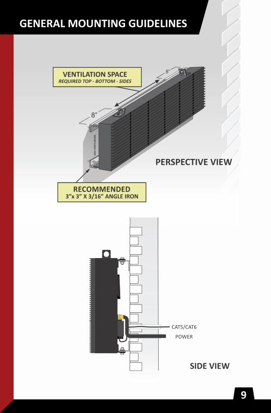
Failure to provide proper ven�la�on can result in the warranty being voided.
Electronic Message Centers (EMCs) require ven�la�on. As Illustrated,
Impact EMCs draw fresh/cool air in through a vent at the bo�om of the
cabinet's rear side, and use cooling
fans located inside the top of the
cabinet to draw cool air up & out
of vents located at the top.
Improper ven�la�on will result in
the EMC overhea�ng. Impact's EMCs
will shut themselves off when they
overheat & will restart a�er cooling.
HOWEVER overhea�ng will cause
damage, thus ven�la�on should be
carefully considered.
8.125"
1.125"
5"2"
A 2" x .125" thick steel moun�ng
angle runs the length of the top and
bo�om of each Impact single cabinet
enclosure EMC. This design provides
tremendous flexibility in moun�ng.
(Angle may vary based on product lineselected. Always refer to drawing formeasurements.)

When installing an IMPACT EMC please adhere to the following
guideline: Allow a minimum of 25 square inches of total air intake
and 25in of exhaust per foot of cabinet length.
Ideal ven�la�on: 2" gap at top/bo�om. Ends may be sealed however
best prac�ce is to use perforated material or vents. Alterna�ve Ven�la�on
Op�ons: If no ven�la�on is available at top: Provide a minimum of a 2"
gap at bo�om, use perforated material withno less than 40% open area
to conceal sides. Air baffles may be required to separate exhaust from
intake. If no ven�la�on is available at top and bo�om: Do not cover sides,
air baffles may be required to separate exhaust from intake. Insufficient
ven�la�on will reduce the life of the EMC and the warranty is subject to
be voided.
2
Impact EMCs are built to last. Both the lightweight aluminum cabinet
and steel moun�ng angle are powder coated for a durable yet subtle
finish. Li�ing plates rings are located at the top of the display and can be
removed a�er installa�on as their threaded cavi�es do not pass through
to the inside of the cabinet - fill cavity with silicone or u�lize the bolt
a�er removing the li�ing plate.

Consult your original quote, the sign’s MET UL48 Standard
Label and/or Impact LED provided shop drawing for
electrical load requirements.
Best prac�ces for power:
- install all signs and sign cabinets per Na�onal Electric Code.
- always follow lock-out/tag-out procedures to ensure safety when working on, installing or connec�ng to electrical lines.
- each electronic message center or LED sign cabinet should be on a dedicated circuit without a photocell or �mer.
- each electronic message center should have an in-earth copper ground rod 3/8” diameter and 6’ long.
- always verify primary power voltage and con�nuity before connec�ng power to the EMC or LED sign cabinet.
- connec�on to the EMC or LED sign should be either:
(a) primary circuit run through conduit directly into the signs terminal block.
(b) primary circuit run to a weather-�ght junc�on box or breaker panel and then a secondary whip connec�ng the junc�on point to the terminal block.
*If you have any ques�ons, please contact the Project
Management department at Impact LED Signs
by calling 1-800-398-0576.
- always check wire color, MET UL48 Standard label on the back of the master unit, and shop drawings to confirm voltage.
Power Out
Data OutData In
Power In
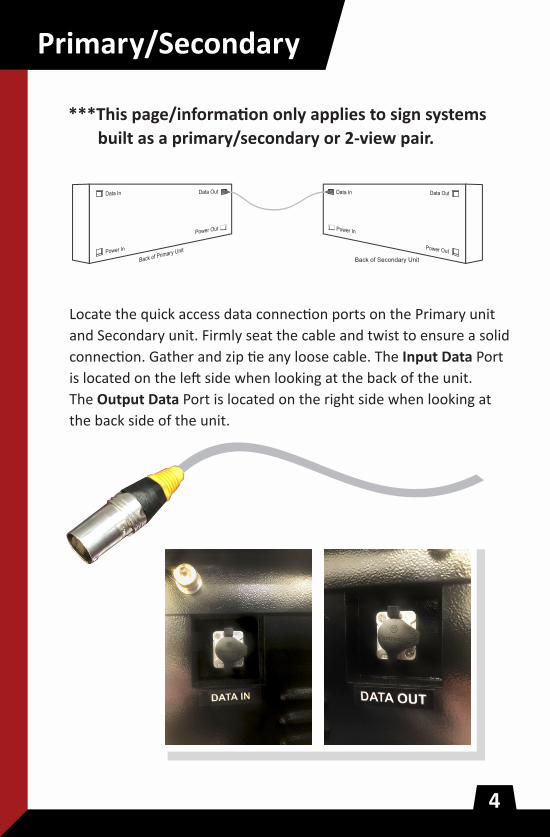
***This page/informa�on only applies to sign systems
built as a primary/secondary or 2-view pair.
Primary/Secondary
Back of Secondary Unit
Locate the quick access data connec�on ports on the Primary unit
and Secondary unit. Firmly seat the cable and twist to ensure a solid
connec�on. Gather and zip �e any loose cable. The Input Data Port
is located on the le� side when looking at the back of the unit.
The Output Data Port is located on the right side when looking at
the back side of the unit.
Back of Primary UnitPower In
Data In Data Out
Power Out
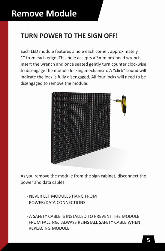
TURN POWER TO THE SIGN OFF!
Each LED module features a hole each corner, approximately
1" from each edge. This hole accepts a 3mm hex head wrench.
Insert the wrench and once seated gently turn counter clockwise
to disengage the module locking mechanism. A “click” sound will
indicate the lock is fully disengaged. All four locks will need to be
disengaged to remove the module.
- A SAFETY CABLE IS INSTALLED TO PREVENT THE MODULE FROM FALLING. ALWAYS REINSTALL SAFETY CABLE WHEN REPLACING MODULE.
As you remove the module from the sign cabinet, disconnect the
power and data cables.
- NEVER LET MODULES HANG FROM
POWER/DATA CONNECTIONS
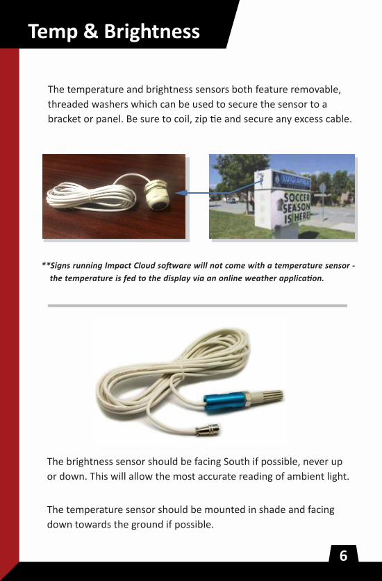
**Signs running Impact Cloud so�ware will not come with a temperature sensor -
the temperature is fed to the display via an online weather applica�on.
The temperature and brightness sensors both feature removable,
threaded washers which can be used to secure the sensor to a
bracket or panel. Be sure to coil, zip �e and secure any excess cable.
The brightness sensor should be facing South if possible, never up
or down. This will allow the most accurate reading of ambient light.
The temperature sensor should be mounted in shade and facing
down towards the ground if possible.
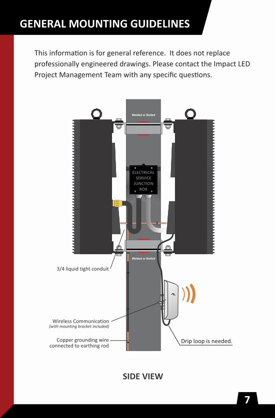
Welded or Bolted
Welded or Bolted
Drip loop is needed.
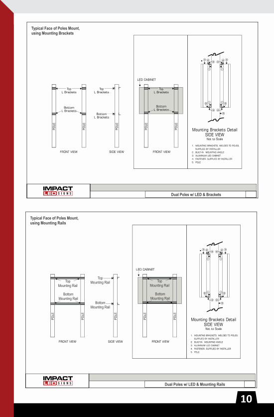
This informa�on is for general reference. It does not replace
professionally engineered drawings. Please contact the Impact LED
Project Management Team with any specific ques�ons.

Steel moun�ng angles are provided on the back of each LED sign
cabinet. Fasteners, support columns, brackets and electrical wiring
conduit/accessories are not provided unless specifically included
as a line item from Impact LED.


DISPLAY GROUNDING GUIDELINES
PRIMARY DISPLAY
SECONDARY DISPLAY
At no point in �me can the display structure (support structure, pole) be used as a means of grounding the display
cabinet. Although a steel structure is conduc�ve, a copper rod maintains to be a superior conductor throughout
the life of the sign. Also, NEC Sec. 250-54 requires the resistance to ground of a single-made electrode to be 25
ohms or less.
It is recommended but not required that each cabinet or display face have an independent grounding rod.
Example of unacceptable grounding.

Connec�vity Methods
Impact LED signs accept a standard ethernet connec�on. This is also
referred to as a cat5e/cat6e cable, network cable, LAN cable or Rj45
ethernet connec�on. A number of different communica�on systems can
be deployed in order to achieve connec�vity with your Impact LED sign;
wifi bridge kit, 4G modem, LAN cable and fiber
line are the most common.
Impact LED u�lizes the Verizon network infrastructure. Connec�vity can
vary from loca�on to loca�on depending on tower coverage and ambient
condi�ons. Even though the 4G modem is mounted and powered inside
the LED sign cabinet, Impact LED provides external antennas with each 4G
modem and requires that they be external to the sign, as high as possible
above the LED sign. It is the Dealers responsibility to securely mount and
document the loca�on of the antenna as well as test connec�vity prior
to leaving the installa�on.
Fiber can be a great op�on for loca�ons with no cellular service who
require connec�vity over a significant distance. Confirm the fiber
specifica�ons with your Impact LED Project Manager prior to installa�on.
Impact LED provides SC fiber media converters which are wide
temperature/industrial grade.
Connec�vity Methods
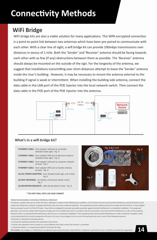
WiFi bridge kits are also a viable solu�on for many applica�ons. This WPA encrypted connec�on
is a point-to-point link between two antennas which have been pre-paired to communicate with
each other. With a clear line of sight, a wifi bridge kit can provide 100mbps transmissions over
distances in excess of 1 mile. Both the ‘Sender’ and ‘Receiver’ antenna should be facing towards
each other with as few (if any) obstruc�ons between them as possible. The ‘Receiver’ antenna
should always be mounted on the outside of the sign. For the longevity of the antenna, we
suggest that installa�ons transmi�ng over short distances a�empt to leave the ‘Sender’ antenna
inside the User’s building. However, it may be necessary to mount the antenna external to the
building if signal is weak or intermi�ent. When installing the building side antenna, connect the
data cable in the LAN port of the POE injector into the local network switch. Then connect the
data cable in the POE port of the POE injector into the antenna.


Create feature content, design reusable templates and save playlists for as
long as you want that will never get lost.
Easily move messages around the screen, enlarge, shrink or rotate content and
try different fonts and colors.
Access and monitor your sign(s) no matter where they are and no matter where
you are at any time.
Instant access to ever expanding library of graphics.
No software updates to download…ever.
Easy to learn, easy to use & easily maximizes the sign’s capabilities to maximize
the power of the display.
Impact Cloud is a user friendly cloud-based communica�on method for any Impact LED sign. This Browser based system works from any tablet, phone or computer with internet access.

Sta�c IP fallback of
192.168.0.218
Antennas are set up to pull a DHCP IP address.
Setup by default to pull a DHCP IP Address
Sta�c IP fallback of
192.168.0.219
The Electronic Message Center Marquee leaves the factory configured for DHCP by default. To ensure a swi� and easy installa�on, the local network may need to be prepped for our cloud controllers. 4G connec�ons are plug and play, requiring no addi�onal configura�on.
General Connectivity ConfigurationGeneral Connectivity ConfigurationGeneral Connectivity ConfigurationOn most networks we find minimal configura�on is needed and the signs are plug and play. Network Traffic for the sign needs to be opened to our Main Server Address.
Cloud Address:Server.cloudled.com
For Cloud signs to communicate properly,
Ports:
We also require network traffic is open to our amazon S3 bucket:weather.cloudled.com
External Network traffic access will need to be granted through all firewalls and all network filtering systems.
This is a basic outline of our network configura�on requirements, there is always the chance that addi�onal changes may need to be made.
For technical ques�ons please reach out to [email protected] or 1-800-398-0576 #3
Network Configuration RequirementsNetwork Configuration RequirementsNetwork Configuration Requirements
HTTPS 443/TCPwebsocket 8443/TCPNTP 123/UDP
Access.Impactledsigns.com
The fall-back addresses are:
Sign Side Radio: 192.168.0.219
Building Side Radio: 192.168.0.218