install guide - mifab
TRANSCRIPT

INSTALL GUIDE
CONTENTS
SPECIAL PRECAUTIONS
LIL-MA X COMPONENTS
GENERAL INSTALL INSTRUCTIONS
BURIED INSTALL ATIONS
LIL-MA X

SPECIAL PRECAUTIONS
1. HIGH TEMPERATURE KITCHEN WATER
2. HYDROSTATIC SL ABS (OR PRESSURE SL ABS)
3. HIGH WATER TABLE INSTALL ATIONS
If there is water entering the interceptor at over 150 F, a drain water tempering valve and approved backflow prevention assembly must be installed. Generally, state and local plumbing codes prohibit water above 150 F from being discharged into the sewer.
Interceptor must be enclosed in a water concrete vault when installed under a hydrostatic slab (slab designed to withstand upward lift- typically caused by hydrostatic pressure).
Interceptor and riser cannot withstand excessive water table height - see max water table height. If possible, interceptor and riser should be installed in a water-tight concrete vault or backfill with concrete or flowable fill (pour wet concrete and flowable backfill in stages to avoid crushing the interceptor).
1
TEMPERING VALVE)
APPROVED BACKFLOWPREVENTION ASSEMBLY
HIGH TEMPERATUREEFFLUENT( >150DEG F)
COLD WATER SUPPLY LINE
DIRECTLY CONNECTED INDIRECTLY CONNECTED
FLOW
FLOW
DTV (DRAIN WATER
MAX WATER TABLE HEIGHTFOR DIRECT BURIAL
4. ODOR ALERT
Do not install air gap on outlet side of interceptor.
WATERTIGHTCONCRETEVAULT
CONCRETE SLAB SUBJECT TO HYDROSTATIC PRESSURE
SPECIAL PRECAUTIONS
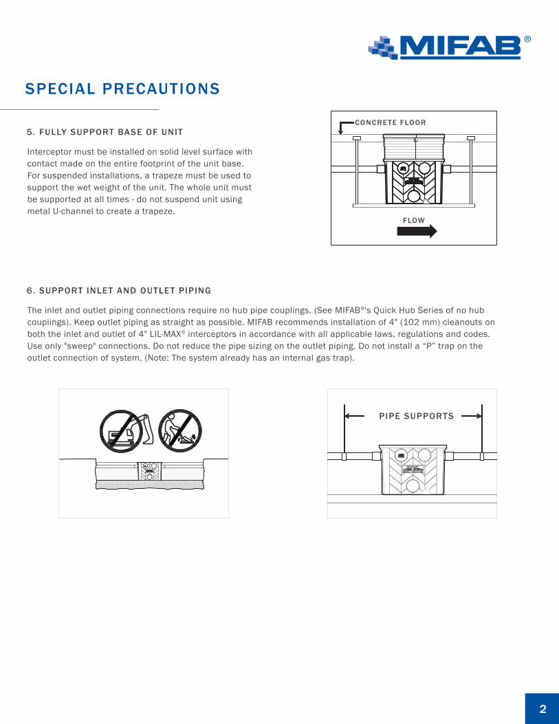
5. FULLY SUPPORT BASE OF UNIT
Interceptor must be installed on solid level surface with contact made on the entire footprint of the unit base. For suspended installations, a trapeze must be used to support the wet weight of the unit. The whole unit must be supported at all times - do not suspend unit using metal U-channel to create a trapeze.
2
CONCRETE FLOOR
FLOW
6. SUPPORT INLET AND OUTLET PIPING
The inlet and outlet piping connections require no hub pipe couplings. (See MIFAB®'s Quick Hub Series of no hub couplings). Keep outlet piping as straight as possible. MIFAB recommends installation of 4" (102 mm) cleanouts on both the inlet and outlet of 4" LIL-MAX® interceptors in accordance with all applicable laws, regulations and codes. Use only "sweep" connections. Do not reduce the pipe sizing on the outlet piping. Do not install a “P” trap on the outlet connection of system. (Note: The system already has an internal gas trap).
PIPE SUPPORTS

LIL-MA X COMPONENTS
3
2
6
5
4
3
5
7
31
OPTIONAL VENTLOCATION(X4)
OPTIONAL SLIPJOINT LOCATION
LID LATCH
INTERCEPTOR LID
BOLT FOR INLET/OUTLET TRAP
INLET TRAP
INLET TRAP SEALING GASKET
INTERNAL FLOW CONTROL
OUTLET TRAP
2 6
5
4
3
1
7

GENERAL INSTALL ATION
ON THE FLOOR INSTALL ATION :Connect piping to interceptor using MIFAB no-hub coupling (See MIFAB's Quick Hub Series of no hub couplings). Ensure all upstream fixtures are trapped properly. Vent per local code.
4
5-1/2" MIN
UNDER SINK :
NEXT TO SINK : FLOOR BELOW :

BURIED INSTALL ATION
1A. Excavate hole at least 6” larger than interceptor on all sides.
5
6"6"
6" 6” OR MORE
1B. Add crushed aggregate (approximately ¾” size rock or
sand, with no fines) to base of hole.
SPECIAL PRECAUTIONS :
3 RISER (25.75") MAXMAX WATER LEVEL
RISERS ARE NOT DESIGNEDTO RETAIN WATER
1. EXCAVATION :

6
BURIED INSTALL ATION
2A. FLOOR SINK INSTALL ATION
3. BACK FILL AND FINISHED GRADE
If your dishwashing sink(s) discharges into a floor drain/sink (drain), you must regulate thed flow into the drain to avoid an overflow of water onto the kitchen floor. This can be done by installing a valve or flow restriction cap on the sink piping that discharges into the drain.
Set interceptor and connect piping using MIFAB no-hub coupling (See MIFAB®'s Quick Hub Series of no-hub couplings). Vent per local code. Fill tank with water so that it remains in place during backfill.
BELOW GRADE WITH RISER (Preferred):
See instructions for LIL-MAX Extension Installation on MIFAB.com. Backfill evenly around tank using crushed aggregate (approximate ¾” size rock or sand, with no fines), finish with a minimum 4” thick conrete pad.
FLUSH-TO-GRADE BURIALS:
Backfill evenly around tank using crushed aggregate(approximately ¾” size rock or sand, with no fines),finish with a minimum 4” thick concrete pad.
CONCRETE PAD BACKFILL TILEMAX LOAD
350 lb.4" MIN.
CONCRETE PAD BACKFILL TILEMAX LOAD
350 lb.4" MIN.
RUBBER FLOWRESTRICTION END CAP
2B. IN- GROUND INSTALL ATION