installation 3.5 mm auxiliary cord...
TRANSCRIPT

Honda Dealer: Please give a copy of these instructions to your customer.
INSTALLATIONINSTRUCTIONS
Accessory Application
© 2018 American Honda Motor Co., Inc. - All Rights Reserved.
PARTS LIST
87952-MKC-A0001 of 6
Publication No.
MII 16426
Issue Date
January 2018
3.5 mm AUXILIARY CORDP/N 08A87-MKC-A00
GL1800/D/B/BDGL1800DA (go to page 7)
No. Description Qty
(1) Installation Instructions URL 1
(2) Auxiliary (AUX) cord 1
(3) Wire tie 1
SUPPLIES REQUIREDSnips
Ruler
Masking tape
Dish soap solution (Water:Dish soap / 100:1)
Shop towel
INSTALLATION CAUTION
• To prevent burns, allow the engine, exhaust system, radiator, etc., to cool before installing the accessory.
NOTE:
• Disconnect the negative (-) cable from the battery before installing this accessory.
• The memory of the clock will be erased when you disconnect the battery. Reset the clock after reconnecting the battery.
• Reinstall the removed parts on the motorcycle and make sure that the wires and harnesses are not pinched.
• Trim the excess ends off the wire ties after attaching them to the wire harnesses. Do not allow the cut part of the wire tie to interfere with another harness or brake hose.
1. Open the left saddlebag lid as shown.
• Repeat on the right side.<Left side>
LEFT SADDLEBAG LID
3. Remove the right side cover in the same manner as the left side.
2. Remove the lef t s ide cover as shown, and disconnect the negative (-) cable of the battery.
LEFT SIDE COVER
(1)
(3)
(2)

2 of 6
4. Remove the seat as shown.
• Disconnect the connector for GL1800/D.
SEAT
BOLT
WASHER
5. Fold down the left rear view mirror backward as shown.
<Left side>
LEFT REAR VIEW MIRROR
6. Remove the left mirror arm panel as shown.
<Left side>
LEFT MIRROR ARM PANEL
SCREW
7. Remove the left rear view mirror as shown.
BOLT
LEFT REAR VIEW MIRRORDisconnect the connector.
8. Remove the right mirror arm panel and right rear view mirror in the same manner as the left side.
9. Remove the screw as shown.
• Repeat on the right side.
<Left side>
SCREW

3 of 6
11. Remove the clip as shown.
CLIP
10. Remove the left deflector panel as shown.
<Left side>
SCREW
LEFT DEFLECTOR PANEL
12. Remove the left inner cowl as shown.
SCREW
SCREW
LEFT INNER COWL
CLIP
CLIP
<Left side>
13. Remove the clip as shown.
CLIP
14. Remove the left middle cowl as shown.
<Left side>
LEFT MIDDLE COWL
15. Remove the right deflector panel, right inner cowl and right middle cowl in the same manner as the left side.
16. Remove the parts as shown.
• Repeat on the right side.
<Left side>
SCREW
SCREWCOLLAR

4 of 6
17. Remove the connector as shown.
<Right side>
2-PIN WATERPROOF CONNECTOR (Black)
18. Remove the clip and disconnect the connector as shown.
CLIP
2-PIN WATERPROOF CONNECTOR (Black)
19. Remove the right outer air guide as shown.
SCREW
CLIPRIGHT OUTER AIR GUIDE
SCREW
20. Remove the pocket cable as shown.
POCKET CABLE

5 of 6
21. Remove the parts as shown.
22. Remove the shelter as shown.
SCREW
CLIP
CLIP
SHELTER
PLUG (Save)POCKET
23. Open the pocket, remove the plug as shown.
170 mm
24. Secure the grommet to the AUX cord with the wire tie as shown.
GROMMET
AUX CORD
AUX CORD
AUX CORD
GROMMET
WIRE TIE
MASKING TAPEProtect the edge.
25. Attach the masking tape as shown.
26. Apply dish soap solution to the position shown.
DISH SOAP SOLUTIONApply.

6 of 6
28. Remove the masking tape.
29. Route and connect the AUX cord as shown.
3-PIN CONNECTOR (White)
AUX CORD
30. Install the motorcycle’s parts in the reverse order of removal.
• Confirm that any wire harness is not caught or too tight.
31. Check the AUX, headlight and the other lights for proper operation.
AUX CORD
AUX CORD
27. Route and install the AUX cord as shown.
GROMMETInsert into the hole.

Honda Dealer: Please give a copy of these instructions to your customer.
INSTALLATION
INSTRUCTIONS
Accessory Application
© 2018 American Honda Motor Co., Inc. - All Rights Reserved.
PARTS LIST
87952-MKC-A300.indd1 of 6
Publication No.
MII 16426
Issue Date
January 2018
3.5 mm AUXILIARY CORD
P/N 08A87-MKC-A00GL1800DA
SUPPLIES REQUIREDElectric drill
Drill bit (12 mm)
Ruler
Masking tape
Dish soap solution
(Water:dish soap / 100:1)
Shop towel
Side cutters
INSTALLATION CAUTION
• To prevent burns, allow the engine, exhaust system, radiator, etc., to cool before installing the accessory.
NOTE:
• Disconnect the negative (-) cable from the battery before installing this accessory.
• The clock memory wil l be erased when you disconnect the battery. Reset the clock after reconnecting the battery.
• Reinstall the removed parts on the motorcycle and make sure that the wires and harnesses are not pinched.
• Trim the excess ends off the wire ties after attaching them to the wire harnesses. Do not allow the cut part of the wire tie to interfere with another harness or brake hose.
No. Description Qty
(1) Installation Instructions URL 1
(2) AUX cord 1
(3) Wire tie 1
(1)
(3)
(2)
1. Open the left saddlebag lid as shown.
• Repeat on the right side.
<Left side>
LEFT SADDLEBAG LID
3. Remove the right side cover in the same manner as the left side.
2. Remove the lef t s ide cover as shown, and disconnect the negative (-) cable from the battery.
LEFT SIDE COVER

2 of 6
4. Remove the seat as shown.
BOLT
WASHER
8. Remove the trunk holder as shown.
TRUNK HOLDER
SCREW
SEATDisconnect
the connector.
5. Remove the right and left passenger grips as shown.7. Disconnect the USB cord as shown.
USB CORD
WASHER
BOLT
RIGHT PASSENGER GRIP
CABLE
LEFT PASSENGER GRIPRemove the cable.
6. Open the rear trunk lid as shown.
• Refer to the Owner’s Manual and use the
emergency trunk cable to open the rear trunk
lid.
REAR TRUNK LID

3 of 6
11. Remove the trunk right side cover as shown.
• Repeat on the left side.
<Right side>
<Left side>
<Right side>
12. Disconnect the connector as shown.
13. Disconnect the USB cord as shown.
14. Disconnect the connector as shown.
MOTORCYCLE’S HARNESS
9. Remove the trunk front lower panel as shown.
12-PIN WATERPROOF CONNECTOR (Black)
USB CORD
12-PIN WATERPROOF CONNECTOR (Black)
MOTORCYCLE’S HARNESS
2-PIN WATERPROOF CONNECTOR (Black)
2-PIN WATERPROOF CONNECTOR (Black)
TRUNK RIGHT SIDE COVER
TRUNK FRONT LOWER PANEL
10. Remove the parts as shown.
• Repeat on the left side.SCREW
SCREW
CLIP
CLIP
4 of 6
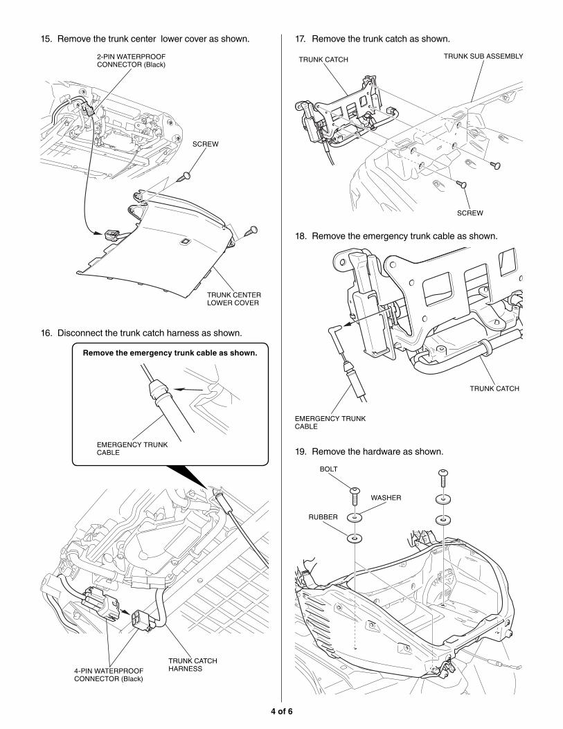
15. Remove the trunk center lower cover as shown.
SCREW
16. Disconnect the trunk catch harness as shown.
17. Remove the trunk catch as shown.
18. Remove the emergency trunk cable as shown.
TRUNK CENTER LOWER COVER
2-PIN WATERPROOF CONNECTOR (Black)
Remove the emergency trunk cable as shown.
EMERGENCY TRUNK CABLE
EMERGENCY TRUNK CABLE
4-PIN WATERPROOF CONNECTOR (Black)
TRUNK CATCH HARNESS
TRUNK CATCH
TRUNK CATCH
SCREW
TRUNK SUB ASSEMBLY
RUBBER
BOLT
WASHER
19. Remove the hardware as shown.

5 of 6
20. Remove the rear trunk and collars as shown. 22. Secure the AUX cord grommet with the wire tie at the distance shown.
21. Drill at the marked line of the rear trunk as shown.
• Drill hole at the center of the marked line.
• Remove the any burrs from the edge of the
hole.
ELECTRIC DRILL (12 mm BIT)
REAR TRUNK
GROMMET
AUX CORDWIRE TIE
MARKED LINE
REAR TRUNK
COLLAR
120 mm
AUX CORD
AUX CORD
GROMMET
MASKING TAPEProtect the edge.
23. Attach the masking tape as shown.
24. Apply dish soap solution to the position shown.
DISH SOAP SOLUTIONApply.

6 of 6
31. Install the motorcycle’s parts in the reverse order of removal.
• Confirm that any wire harness is not caught or
too tight.
32. Check the AUX, headlight and the other lights for proper operation.
26. Remove the masking tape.
27. Install the rear trunk in the reverse order of removal.
28. Route the AUX cord as shown.
30. Connect the AUX cord as shown.
• Return the boots to the original position.
MOTORCYCLE’S HARNESS
3-PIN CONNECTOR (White)
AUX CORD
AUX CORD
AUX CORD
25. Route and install the AUX cord as shown.
29. Move the boots as shown.
GROMMETInsert into the hole.
AUX CORD
OPENED HOLE
BOOTMove.