installation
TRANSCRIPT

Installation and Upgrades
for the
Avaya™ G700 Media Gateway
controlled by an
Avaya™ S8300 Media Server or an
Avaya™ S8700 Media Server
555-234-100Issue 3
May 2003

Copyright 2003, Avaya Inc.All Rights Reserved
Notice
Every effort was made to ensure that the information in this document was complete and accurate at the time of printing. However, information is subject to change.
Preventing Toll Fraud
“Toll fraud” is the unauthorized use of your telecommunications system by an unauthorized party (for example, a person who is not a corporate employee, agent, subcontractor, or is not working on your company's behalf). Be aware that there may be a risk of toll fraud associated with your system and that, if toll fraud occurs, it can result in substantial additional charges for your telecommunications services.
Avaya Fraud Intervention
If you suspect that you are being victimized by toll fraud and you need technical assistance or support, in the United States and Canada, call the Technical Service Center's Toll Fraud Intervention Hotline at1-800-643-2353.
How to Get Help
For additional support telephone numbers, go to the Avaya Web site:
http:/www.avaya.com/support/
If you are:• Within the United States, click Escalation Lists, which includes
escalation phone numbers within the USA.• Outside the United States, click Escalation Lists then click Global
Escalation List, which includes phone numbers for the regional Centers of Excellence.
Providing Telecommunications Security
Telecommunications security (of voice, data, and/or video communications) is the prevention of any type of intrusion to (that is, either unauthorized or malicious access to or use of) your company's telecommunications equipment by some party.
Your company's “telecommunications equipment” includes both this Avaya product and any other voice/data/video equipment that could be accessed via this Avaya product (that is, “networked equipment”).
An “outside party” is anyone who is not a corporate employee, agent, subcontractor, or is not working on your company's behalf. Whereas, a “malicious party” is anyone (including someone who may be otherwise authorized) who accesses your telecommunications equipment with either malicious or mischievous intent.
Such intrusions may be either to/through synchronous (time-multiplexed and/or circuit-based) or asynchronous (character-, message-, or packet-based) equipment or interfaces for reasons of:
• Utilization (of capabilities special to the accessed equipment)• Theft (such as, of intellectual property, financial assets, or toll-
facility access)• Eavesdropping (privacy invasions to humans)• Mischief (troubling, but apparently innocuous, tampering)• Harm (such as harmful tampering, data loss or alteration,
regardless of motive or intent)
Be aware that there may be a risk of unauthorized intrusions associated with your system and/or its networked equipment. Also realize that, if such an intrusion should occur, it could result in a
variety of losses to your company (including but not limited to, human/data privacy, intellectual property, material assets, financial resources, labor costs, and/or legal costs).
Responsibility for Your Company’s Telecommunications Security
The final responsibility for securing both this system and its networked equipment rests with you - Avaya’s customer system administrator, your telecommunications peers, and your managers. Base the fulfillment of your responsibility on acquired knowledge and resources from a variety of sources including but not limited to:
• Installation documents• System administration documents• Security documents• Hardware-/software-based security tools• Shared information between you and your peers• Telecommunications security experts
To prevent intrusions to your telecommunications equipment, you and your peers should carefully program and configure:
• Your Avaya-provided telecommunications systems and their interfaces
• Your Avaya-provided software applications, as well as their underlying hardware/software platforms and interfaces
• Any other equipment networked to your Avaya products.
Voice Over Internet Protocol (VoIP)
If the equipment supports Voice over Internet Protocol (VoIP) facilities, you may experience certain compromises in performance, reliability and security, even when the equipment performs as warranted. These compromises may become more acute if you fail to follow Avaya's recommendations for configuration, operation and use of the equipment. YOU ACKNOWLEDGE THAT YOU ARE AWARE OF THESE RISKS AND THAT YOU HAVE DETERMINED THEY ARE ACCEPTABLE FOR YOUR APPLICATION OF THE EQUIPMENT. YOU ALSO ACKNOWLEDGE THAT, UNLESS EXPRESSLY PROVIDED IN ANOTHER AGREEMENT, YOU ARE SOLELY RESPONSIBLE FOR (1) ENSURING THAT YOUR NETWORKS AND SYSTEMS ARE ADEQUATELY SECURED AGAINST UNAUTHORIZED INTRUSION AND (2) BACKING UP YOUR DATA AND FILES.
Standards Compliance
Avaya Inc. is not responsible for any radio or television interference caused by unauthorized modifications of this equipment or the substitution or attachment of connecting cables and equipment other than those specified by Avaya Inc. The correction of interference caused by such unauthorized modifications, substitution or attachment will be the responsibility of the user. Pursuant to Part 15 of the Federal Communications Commission (FCC) Rules, the user is cautioned that changes or modifications not expressly approved by Avaya Inc. could void the user’s authority to operate this equipment.
Product Safety Standards
This product complies with and conforms to the following international Product Safety standards as applicable:
Safety of Information Technology Equipment, IEC 60950, 3rd Edition including all relevant national deviations as listed in Compliance with IEC for Electrical Equipment (IECEE) CB-96A.
Safety of Information Technology Equipment, CAN/CSA-C22.2 No. 60950-00 / UL 60950, 3rd Edition
Safety Requirements for Customer Equipment, ACA Technical Standard (TS) 001 - 1997

One or more of the following Mexican national standards, as applicable: NOM 001 SCFI 1993, NOM SCFI 016 1993, NOM 019 SCFI 1998
The equipment described in this document may contain Class 1 LASER Device(s). These devices comply with the following standards:
• EN 60825-1, Edition 1.1, 1998-01• 21 CFR 1040.10 and CFR 1040.11.
The LASER devices operate within the following parameters:• Maximum power output: -5 dBm to -8 dBm• Center Wavelength: 1310 nm to 1360 nm
Luokan 1 LaserlaiteKlass 1 Laser Apparat
Use of controls or adjustments or performance of procedures other than those specified herein may result in hazardous radiation exposures. Contact your Avaya representative for more laser product information.
Electromagnetic Compatibility (EMC) Standards
This product complies with and conforms to the following international EMC standards and all relevant national deviations:
Limits and Methods of Measurement of Radio Interference of Information Technology Equipment, CISPR 22:1997 and EN55022:1998.
Information Technology Equipment – Immunity Characteristics – Limits and Methods of Measurement, CISPR 24:1997 and EN55024:1998, including:
• Electrostatic Discharge (ESD) IEC 61000-4-2• Radiated Immunity IEC 61000-4-3• Electrical Fast Transient IEC 61000-4-4• Lightning Effects IEC 61000-4-5• Conducted Immunity IEC 61000-4-6• Mains Frequency Magnetic Field IEC 61000-4-8• Voltage Dips and Variations IEC 61000-4-11• Powerline Harmonics IEC 61000-3-2• Voltage Fluctuations and Flicker IEC 61000-3-3
Federal Communications Commission Statement
Part 15:
Part 68: Answer-Supervision Signaling. Allowing this equipment to be operated in a manner that does not provide proper answer-supervision signaling is in violation of Part 68 rules. This equipment returns answer-supervision signals to the public switched network when:
• answered by the called station, • answered by the attendant, or • routed to a recorded announcement that can be administered by
the customer premises equipment (CPE) user.
This equipment returns answer-supervision signals on all direct inward dialed (DID) calls forwarded back to the public switched telephone network. Permissible exceptions are:
• A call is unanswered.• A busy tone is received.• A reorder tone is received.
Avaya attests that this registered equipment is capable of providing users access to interstate providers of operator services through the use of access codes. Modification of this equipment by call aggregators to block access dialing codes is a violation of the Telephone Operator Consumers Act of 1990.
This equipment complies with Part 68 of the FCC Rules and the requirements adopted by the ACTA. On the rear of this equipment is a label that contains, among other information, a product identifier in the format US:AAAEQ##TXXXX. The digits represented by ## are REN without a decimal point (e.g., 03 is a REN of 0.3). If requested, this information must be provided to the telephone company.
The REN is used to determine the quantity of devices which may be connected to the telephone line. Excessive RENs on the telephone line may result in devices not ringing in response to an incoming call. In most, but not all areas, the sum of RENs should not exceed 5.0. To be certain of the number of devices that may be connected to a line, as determined by the total RENs, contact the local telephone company.REN is not required for some types of analog or digital facilities.
Means of Connection
Connection of this equipment to the telephone network is shown in the following table.
If the terminal equipment (for example, the media server or media gateway) causes harm to the telephone network, the telephone company will notify you in advance that temporary discontinuance of service may be required. But if advance notice is not practical, the telephone company will notify the customer as soon as possible. Also, you will be advised of your right to file a complaint with the FCC if you believe it is necessary.
The telephone company may make changes in its facilities, equipment, operations or procedures that could affect the operation of the equipment. If this happens, the telephone company will provide advance notice in order for you to make necessary modifications to maintain uninterrupted service.
Note: This equipment has been tested and found to comply with the limits for a Class B digital device, pursuant to Part 15 of the FCC Rules. These limits are designed to provide reasonable protection against harmful interference in a residential installation. This equipment generates, uses, and can radiate radio frequency energy and, if not installed and used in accordance with the instruction manual, may cause harmful interference to radio communications. However, there is no guarantee that interference will not occur in a particular installation. If this equipment does cause harmful interference to radio or television reception, which can be determined by turning the equipment off and on, the user is encouraged to try to correct the interference by one or more of the following measures:
• Reorient or relocate the receiving antenna.• Increase the separation between the equipment and receiver.• Connect the equipment into an outlet on a circuit different
from that to which the receiver is connected.• Consult the dealer or an experienced radio/TV technician for
help.
Manufacturer’s Port Identi-fier
FIC Code SOC/REN/A.S. Code
Network Jacks
Ground Start CO trunk 02GS2 0.5A RJ11C
DID trunk 02RV2-T AS.0 RJ11C
Loop Start CO trunk 02LS2 0.5A RJ11C
1.544 digital interface 04DU9-BN 6.0Y RJ48C
04DU9-DN 6.0Y RJ48C
04DU9-IKN 6.0Y RJ48C
04DU9-ISN 6.0Y RJ48C
Basic Rate Interface 02IS5 6.0F RJ49C

If trouble is experienced with this equipment, for repair or warranty information, please contact the Technical Service Center at 1-800-242-2121 or contact your local Avaya representative. If the equipment is causing harm to the telephone network, the telephone company may request that you disconnect the equipment until the problem is resolved.
A plug and jack used to connect this equipment to the premises wiring and telephone network must comply with the applicable FCC Part 68 rules and requirements adopted by the ACTA. A compliant telephone cord and modular plug is provided with this product. It is designed to be connected to a compatible modular jack that is also compliant.
It is recommended that repairs be performed by Avaya certified technicians.
The equipment cannot be used on public coin phone service provided by the telephone company. Connection to party line service is subject to state tariffs. Contact the state public utility commission, public service commission or corporation commission for information.
This equipment, if it uses a telephone receiver, is hearing aid compatible.
Canadian Department of Communications (DOC) Interference Information
This Class B digital apparatus complies with Canadian ICES-003.
Cet appareil numérique de la classe B est conforme à la norme NMB-003 du Canada.
This equipment meets the applicable Industry Canada Terminal Equipment Technical Specifications. This is confirmed by the registration number. The abbreviation, IC, before the registration number signifies that registration was performed based on a Declaration of Conformity indicating that Industry Canada technical specifications were met. It does not imply that Industry Canada approved the equipment.
DECLARATIONS OF CONFORMITY
United States FCC Part 68 Supplier’s Declaration of Conformity (SDoC)
Avaya Inc. in the United States of America hereby certifies that the equipment described in this document and bearing a TIA TSB-168 label identification number complies with the FCC’s Rules and Regulations 47 CFR Part 68, and the Administrative Council on Terminal Attachments (ACTA) adopted technical criteria.
Avaya further asserts that Avaya handset-equipped terminal equipment described in this document complies with Paragraph 68.316 of the FCC Rules and Regulations defining Hearing Aid Compatibility and is deemed compatible with hearing aids.Copies of SDoCs signed by the Responsible Party in the U. S. can be obtained by contacting your local sales representative and are available on the following Web site:
http://www.avaya.com/support
All Avaya media servers and media gateways are compliant with FCC Part 68, but many have been registered with the FCC before the SDoC process was available. A list of all Avaya registered products may be found at:
http://www.part68.org/
by conducting a search using “Avaya” as manufacturer.
European Union Declarations of Conformity
Avaya Inc. declares that the equipment specified in this document bearing the “CE” (Conformité Europeénne) mark conforms to the European Union Radio and Telecommunications Terminal Equipment Directive (1999/5/EC), including the Electromagnetic Compatibility Directive (89/336/EEC, Class B) and Low Voltage Directive (73/23/EEC). This equipment has been certified to meet CTR3 Basic Rate Interface (BRI) and CTR4 Primary Rate Interface (PRI) and subsets thereof in CTR12 and CTR13, as applicable.
Copies of these Declarations of Conformity (DoCs) can be obtained by contacting your local sales representative and are available on the following Web site:
http://www.avaya.com/support
Japan
This is a Class B product based on the standard of the Voluntary Control Council for Interference by Information Technology Equipment (VCCI). If this equipment is used in a domestic environment, radio disturbance may occur, in which case, the user may be required to take corrective actions.
To order copies of this and other documents:
Call: Avaya Publications Center
Voice 1.800.457.1235 or 1.207.866.6701FAX 1.800.457.1764 or 1.207.626.7269
Write: Globalware Solutions200 Ward Hill AvenueHaverhill, MA 01835 USAAttention: Avaya Account Management
E-mail: [email protected]
For the most current versions of documentation, go to the Avaya Web site:
http://www.avaya.com/support/

Installation and Upgrades for G700 with S8300 or S8700555-234-100 — Issue 3 — May 2003 5
ContentsAbout This Book 15
Audience . . . . . . . . . . . . . . . . . . . . . . . . . . . . . . . . . . . . . . . . . . . . . . . . . . . . . . . . . . . . 15
Using this book . . . . . . . . . . . . . . . . . . . . . . . . . . . . . . . . . . . . . . . . . . . . . . . . . . . . . . . 16
Conventions . . . . . . . . . . . . . . . . . . . . . . . . . . . . . . . . . . . . . . . . . . . . . . . . . . . . . . . . . 17Physical dimensions . . . . . . . . . . . . . . . . . . . . . . . . . . . . . . . . . . . . . . . . . . . . . . . . 17Terminology . . . . . . . . . . . . . . . . . . . . . . . . . . . . . . . . . . . . . . . . . . . . . . . . . . . . . . 17Typography. . . . . . . . . . . . . . . . . . . . . . . . . . . . . . . . . . . . . . . . . . . . . . . . . . . . . . . 17
Commands. . . . . . . . . . . . . . . . . . . . . . . . . . . . . . . . . . . . . . . . . . . . . . . . . . . . 17Keys . . . . . . . . . . . . . . . . . . . . . . . . . . . . . . . . . . . . . . . . . . . . . . . . . . . . . . . . . 18User input . . . . . . . . . . . . . . . . . . . . . . . . . . . . . . . . . . . . . . . . . . . . . . . . . . . . . 18System output and field names . . . . . . . . . . . . . . . . . . . . . . . . . . . . . . . . . . . . 18
Downloading this book and updates from the Web. . . . . . . . . . . . . . . . . . . . . . . . . . . . 19Downloading this book . . . . . . . . . . . . . . . . . . . . . . . . . . . . . . . . . . . . . . . . . . . . . . 19
Safety labels and security alert labels . . . . . . . . . . . . . . . . . . . . . . . . . . . . . . . . . . . . . . 20
Related resources . . . . . . . . . . . . . . . . . . . . . . . . . . . . . . . . . . . . . . . . . . . . . . . . . . . . . 20
Technical assistance . . . . . . . . . . . . . . . . . . . . . . . . . . . . . . . . . . . . . . . . . . . . . . . . . . . 21Within the US . . . . . . . . . . . . . . . . . . . . . . . . . . . . . . . . . . . . . . . . . . . . . . . . . . . . . 21International . . . . . . . . . . . . . . . . . . . . . . . . . . . . . . . . . . . . . . . . . . . . . . . . . . . . . . 21
Trademarks . . . . . . . . . . . . . . . . . . . . . . . . . . . . . . . . . . . . . . . . . . . . . . . . . . . . . . . . . . 21
Ordering Documentation . . . . . . . . . . . . . . . . . . . . . . . . . . . . . . . . . . . . . . . . . . . . . . . . 21
Sending us comments. . . . . . . . . . . . . . . . . . . . . . . . . . . . . . . . . . . . . . . . . . . . . . . . . . 22
Chapter 1 Roadmap and Reference 23
Wizards for Installations and Upgrades. . . . . . . . . . . . . . . . . . . . . . . . . . . . . . . . . . . . . 24The Avaya Installation Wizard (IW) . . . . . . . . . . . . . . . . . . . . . . . . . . . . . . . . . . . . 24
What the IW Does and Does Not Do . . . . . . . . . . . . . . . . . . . . . . . . . . . . . . . . 25Electronic Worksheets and Templates. . . . . . . . . . . . . . . . . . . . . . . . . . . . . . . 25
The LSP/G700 Upgrade Tool . . . . . . . . . . . . . . . . . . . . . . . . . . . . . . . . . . . . . . . . . 26The Avaya Gateway Installation Wizard (GIW) . . . . . . . . . . . . . . . . . . . . . . . . . . . 28
Installation Roadmap and Task Lists . . . . . . . . . . . . . . . . . . . . . . . . . . . . . . . . . . . . . . 29Checklist 1:Install a New G700 with an S8300 (Primary or LSP) . . . . . . . . . . . . . . . . . . . . . . . . . . . . . . . . . . . . . . . 30Checklist 2:Install a New G700 without an S8300. . . . . . . . . . . . . . . . . . . . . . . . . . . . . . . . . . . 33Checklist 3Upgrade an Existing G700 with anS8300 (Primary or LSP) . . . . . . . . . . . . . . . . . . . . . . . . . . . . . . . . . . . . . . . . . . . . . 35

Contents
6 Installation and Upgrades for G700 with S8300 or S8700555-234-100 — Issue 3 — May 2003
Checklist 4:Upgrade an Existing G700 withoutan S8300 . . . . . . . . . . . . . . . . . . . . . . . . . . . . . . . . . . . . . . . . . . . . . . . . . . . . . . . . 37
Connection and Login Methods. . . . . . . . . . . . . . . . . . . . . . . . . . . . . . . . . . . . . . . . . . . 38Connection Overview . . . . . . . . . . . . . . . . . . . . . . . . . . . . . . . . . . . . . . . . . . . . . . . 39
Summary of S8300 and G700 Access Methods and Tasks . . . . . . . . . . . . . . 39Laptop Configuration for a Direct Connection to the Services Port . . . . . . . . . . . . 40
Settings for a Direct Connection to S8300 or S8700 Services Port . . . . . . . . . 40Connection Methods. . . . . . . . . . . . . . . . . . . . . . . . . . . . . . . . . . . . . . . . . . . . . . . . 44
Connect Laptop to Services Port of S8300 . . . . . . . . . . . . . . . . . . . . . . . . . . . 44Connect Laptop to the G700 Serial Port . . . . . . . . . . . . . . . . . . . . . . . . . . . . . 44Connect Laptop to Customer LAN . . . . . . . . . . . . . . . . . . . . . . . . . . . . . . . . . . 45Connect the External Modem to the S8300 Media Server: . . . . . . . . . . . . . . . 45Set up Windows for Modem Connection to the Media Server (Windows 2000 or XP) . . . . . . . . . . . . . . . . . . . . . . . . . . . . . . . . . . . . . . . . . . . 46Configure the Remote PC for PPP Modem Connection (Windows 2000 or XP, Terminal Emulator, or ASA) . . . . . . . . . . . . . . . . . . . . . . . . . . . . . . . . . . . . . . . 46Use Windows for PPP Modem Connection (Windows 2000 or XP). . . . . . . . . 47Use Avaya Terminal Emulator for LAN Connection to Communication Manager . . . . . . . . . . . . . . . . . . . . . . . . . . . . . . . . . . . . . . . . . 47Use Avaya Terminal Emulator for Modem Connection to Communication Manager . . . . . . . . . . . . . . . . . . . . . . . . . . . . . . . . . . . . . . . . . . . . . . . . . . . . . . 48
Log in Methods . . . . . . . . . . . . . . . . . . . . . . . . . . . . . . . . . . . . . . . . . . . . . . . . . . . 49Log in to the Media Server from Your Laptop using Telnet . . . . . . . . . . . . . . . 50Log in to the S8300 Web Interface from Your Laptop . . . . . . . . . . . . . . . . . . . 50S8300 Main Menu . . . . . . . . . . . . . . . . . . . . . . . . . . . . . . . . . . . . . . . . . . . . . . 54Open the Communication Manager SAT Screens . . . . . . . . . . . . . . . . . . . . . . 55Log in to the P330 stack Processor with a Direct Connection to the Services Port . . . . . . . . . . . . . . . . . . . . . . . . . . . . . . . . . . . . . . . . . . . . . . . . . 55Log in to the P330 Stack Processor with a LAN Connection . . . . . . . . . . . . . 56Log in to the P330 Stack Processor with a Direct Serial Connection. . . . . . . . 56Log in to the P330 Stack Processor with Device Manager . . . . . . . . . . . . . . . 56
Avaya Site Administration . . . . . . . . . . . . . . . . . . . . . . . . . . . . . . . . . . . . . . . . . . 57Configure Avaya Site Administration . . . . . . . . . . . . . . . . . . . . . . . . . . . . . . . . 57
Navigational Aid for CLI Commands . . . . . . . . . . . . . . . . . . . . . . . . . . . . . . . . . . . . . . . 59
Terminal Emulation Function Keys for Communication Manager . . . . . . . . . . . . . . . . . 60

Contents
Installation and Upgrades for G700 with S8300 or S8700555-234-100 — Issue 3 — May 2003
7
Chapter 2 Installing Hardware for the G700 Media Gateway andS8300 Media Server 61
Getting Started . . . . . . . . . . . . . . . . . . . . . . . . . . . . . . . . . . . . . . . . . . . . . . . . . . . . . . . 62G700 Media Gateway . . . . . . . . . . . . . . . . . . . . . . . . . . . . . . . . . . . . . . . . . . . . . . . 62
G700 Media Gateway Chassis and Processors. . . . . . . . . . . . . . . . . . . . . . . . 62Media Modules . . . . . . . . . . . . . . . . . . . . . . . . . . . . . . . . . . . . . . . . . . . . . . . . . 62Data Expansion Modules . . . . . . . . . . . . . . . . . . . . . . . . . . . . . . . . . . . . . . . . . 63
Media Servers. . . . . . . . . . . . . . . . . . . . . . . . . . . . . . . . . . . . . . . . . . . . . . . . . . . . . 65S8300 Media Server. . . . . . . . . . . . . . . . . . . . . . . . . . . . . . . . . . . . . . . . . . . . . 65Local Survivable Processor (LSP) . . . . . . . . . . . . . . . . . . . . . . . . . . . . . . . . . . 65S8700 Media Server. . . . . . . . . . . . . . . . . . . . . . . . . . . . . . . . . . . . . . . . . . . . . 65
Endpoint and Adjunct Components . . . . . . . . . . . . . . . . . . . . . . . . . . . . . . . . . . . . 66Plan the Installation. . . . . . . . . . . . . . . . . . . . . . . . . . . . . . . . . . . . . . . . . . . . . . . . . 66
Use the Planning Documentation. . . . . . . . . . . . . . . . . . . . . . . . . . . . . . . . . . . 67SSO Authentication Login . . . . . . . . . . . . . . . . . . . . . . . . . . . . . . . . . . . . . . . . 67Site Verification . . . . . . . . . . . . . . . . . . . . . . . . . . . . . . . . . . . . . . . . . . . . . . . . 67Network Integration . . . . . . . . . . . . . . . . . . . . . . . . . . . . . . . . . . . . . . . . . . . . . 67
Installation and Cabling . . . . . . . . . . . . . . . . . . . . . . . . . . . . . . . . . . . . . . . . . . . . . . . . . 68On Site Checklist . . . . . . . . . . . . . . . . . . . . . . . . . . . . . . . . . . . . . . . . . . . . . . . . . . 68
Environmental Verification . . . . . . . . . . . . . . . . . . . . . . . . . . . . . . . . . . . . . . . . 68Power Verification . . . . . . . . . . . . . . . . . . . . . . . . . . . . . . . . . . . . . . . . . . . . . . 69Grounding Verification . . . . . . . . . . . . . . . . . . . . . . . . . . . . . . . . . . . . . . . . . . . 69
Unpack and Check the Order . . . . . . . . . . . . . . . . . . . . . . . . . . . . . . . . . . . . . . . . . 69Install the G700 Media Gateway. . . . . . . . . . . . . . . . . . . . . . . . . . . . . . . . . . . . . . . 70
Prepare the G700 Media Gateway. . . . . . . . . . . . . . . . . . . . . . . . . . . . . . . . . . 70Mount the G700 Media Gateway in the Rack. . . . . . . . . . . . . . . . . . . . . . . . . . 71
Insert the Avaya S8300 Media Server (If Necessary for Standalone Service or LSP) . . . . . . . . . . . . . . . . . . . . . . . . . . . . 73Insert the Media Modules . . . . . . . . . . . . . . . . . . . . . . . . . . . . . . . . . . . . . . . . . . . . 75Insert an Expansion Module . . . . . . . . . . . . . . . . . . . . . . . . . . . . . . . . . . . . . . . . . . 77Insert an Avaya X330STK Stacking Module . . . . . . . . . . . . . . . . . . . . . . . . . . . . . . 77Cable Multiple Units . . . . . . . . . . . . . . . . . . . . . . . . . . . . . . . . . . . . . . . . . . . . . . . . 78Attach Ground Conductors . . . . . . . . . . . . . . . . . . . . . . . . . . . . . . . . . . . . . . . . . . . 81
General Grounding Requirements . . . . . . . . . . . . . . . . . . . . . . . . . . . . . . . . . . 81Approved Grounds . . . . . . . . . . . . . . . . . . . . . . . . . . . . . . . . . . . . . . . . . . . . . . 82Connect the Safety Ground . . . . . . . . . . . . . . . . . . . . . . . . . . . . . . . . . . . . . . . 83
Connect AC Power . . . . . . . . . . . . . . . . . . . . . . . . . . . . . . . . . . . . . . . . . . . . . . . . . 84Power Requirements . . . . . . . . . . . . . . . . . . . . . . . . . . . . . . . . . . . . . . . . . . . . 84Test the AC Outlet . . . . . . . . . . . . . . . . . . . . . . . . . . . . . . . . . . . . . . . . . . . . . . 85Plug in AC Power . . . . . . . . . . . . . . . . . . . . . . . . . . . . . . . . . . . . . . . . . . . . . . . 86
S8300 LED Indicators . . . . . . . . . . . . . . . . . . . . . . . . . . . . . . . . . . . . . . . . . . . . . . . 87

Contents
8 Installation and Upgrades for G700 with S8300 or S8700555-234-100 — Issue 3 — May 2003
Chapter 3 Installing a New G700 with an S8300 89
Installation Overview . . . . . . . . . . . . . . . . . . . . . . . . . . . . . . . . . . . . . . . . . . . . . . . . . . . 89Initial Access to the G700 . . . . . . . . . . . . . . . . . . . . . . . . . . . . . . . . . . . . . . . . 90Access to the S8300 and G700 . . . . . . . . . . . . . . . . . . . . . . . . . . . . . . . . . . . . 90
Before Going to the Customer Site . . . . . . . . . . . . . . . . . . . . . . . . . . . . . . . . . . . . . . . . 92Get Planning Forms from the Project Manager . . . . . . . . . . . . . . . . . . . . . . . . 92Get the Serial Number of the G700, if Necessary . . . . . . . . . . . . . . . . . . . . . . . . . . . . . . . . . . . . . . . . . . . . . . . . . . . 92Check FTP Server for Backing up Data . . . . . . . . . . . . . . . . . . . . . . . . . . . . . . 92Complete the RFA Processes . . . . . . . . . . . . . . . . . . . . . . . . . . . . . . . . . . . . 92License File and Communication Manager Versions for a Local Survivable Processor . . . . . . . . . . . . . . . . . . . . . . . . . . . . . . . . . . . . . . . . . . . . . . . . . . . . . 93Download Update Software to Your Laptop, if Necessary . . . . . . . . . . . . . . . . 93
On Site Preparation for the Installation . . . . . . . . . . . . . . . . . . . . . . . . . . . . . . . . . . . . . 95Install the New License File, If Necessary . . . . . . . . . . . . . . . . . . . . . . . . . . . . . . . 95Determine Necessary Upgrades to the S8300 . . . . . . . . . . . . . . . . . . . . . . . . . . . . 98Transfer Files from a CD or Hard Drive of Laptop . . . . . . . . . . . . . . . . . . . . . . . . . 99
Install New Software on the S8300 . . . . . . . . . . . . . . . . . . . . . . . . . . . . . . . . . . . . . . . 101
Configure the S8300 . . . . . . . . . . . . . . . . . . . . . . . . . . . . . . . . . . . . . . . . . . . . . . . . . . 109Provide the keys.install File (If Necessary) . . . . . . . . . . . . . . . . . . . . . . . . . . . . . . 122
Configure the G700 Media Gateway . . . . . . . . . . . . . . . . . . . . . . . . . . . . . . . . . . . . . . 124Assign the IP Addresses of the G700 Media Gateway Components . . . . . . . . . . 124
Check for IP Connections . . . . . . . . . . . . . . . . . . . . . . . . . . . . . . . . . . . . . . . 128Set up the Controller List for the G700 Media Gateway . . . . . . . . . . . . . . . . . . . . 129
Set the LSP Transition Points . . . . . . . . . . . . . . . . . . . . . . . . . . . . . . . . . . . . 130Configure an X330 Expansion Module (If Necessary) . . . . . . . . . . . . . . . . . . . . . 131
Install New Firmware on the G700 . . . . . . . . . . . . . . . . . . . . . . . . . . . . . . . . . . . . . . 132Verify the Contents of the tftpboot Directory . . . . . . . . . . . . . . . . . . . . . . . . . 132Determine Which Firmware to Install on the G700. . . . . . . . . . . . . . . . . . . . . 132Install New Firmware on the P330 Stack Processor . . . . . . . . . . . . . . . . . . . 134Install New Firmware on the G700 Media Gateway Processor . . . . . . . . . . . 134Install New Firmware on the Media Modules . . . . . . . . . . . . . . . . . . . . . . . . . 136Install New Firmware on Other G700 Media Gateways (Stack Configuration) 137Install New Firmware on Other G700 Media Gateways (Remote, No Stack Configuration). . . . . . . . . . . . . . . . . . . . . . . . . . . . . . . . . . . . . . . . . . . . . . . . . 138
Administer Communication Manager . . . . . . . . . . . . . . . . . . . . . . . . . . . . . . . . . . . . . 139The Primary Controller is an S8300 . . . . . . . . . . . . . . . . . . . . . . . . . . . . . . . . . . . 139
Assign Node Names and IP Addresses for the LSPs . . . . . . . . . . . . . . . . . . 139Administer Network Regions . . . . . . . . . . . . . . . . . . . . . . . . . . . . . . . . . . . . . 140Associate LSPs with Network Regions . . . . . . . . . . . . . . . . . . . . . . . . . . . . . 141

Contents
Installation and Upgrades for G700 with S8300 or S8700555-234-100 — Issue 3 — May 2003
9
Administer IP Interfaces . . . . . . . . . . . . . . . . . . . . . . . . . . . . . . . . . . . . . . . . . 143Administer the LSP Form . . . . . . . . . . . . . . . . . . . . . . . . . . . . . . . . . . . . . . . . 143
The Primary Controller is an S8700(the S8300 Is an LSP). . . . . . . . . . . . . . . . . . . . . . . . . . . . . . . . . . . . . . . . . . . . . . 145
Assign Node Names and IP Addresses for the C-LANs and LSPs . . . . . . . . 145Administer Network Regions . . . . . . . . . . . . . . . . . . . . . . . . . . . . . . . . . . . . . 146Assign LSPs to the Network Regions. . . . . . . . . . . . . . . . . . . . . . . . . . . . . . . 149Administer IP Interfaces . . . . . . . . . . . . . . . . . . . . . . . . . . . . . . . . . . . . . . . . . 150Administer the LSP Form . . . . . . . . . . . . . . . . . . . . . . . . . . . . . . . . . . . . . . . . 152
Administer the Media Gateway . . . . . . . . . . . . . . . . . . . . . . . . . . . . . . . . . . . . . . . 153
Considerations for IP Phones Supported by a Local Survivable Processor . . . . . . . . 156Transition of Control from Primary Controller to LSP . . . . . . . . . . . . . . . . . . . 156
Set Up SNMP Alarming on the G700 . . . . . . . . . . . . . . . . . . . . . . . . . . . . . . . . . . . . . 157
Complete the Installation of S8300(if the Primary Controller) . . . . . . . . . . . . . . . . . . . . . . . . . . . . . . . . . . . . . . . . . . . . . . 159
Complete the Installation Process. . . . . . . . . . . . . . . . . . . . . . . . . . . . . . . . . . . . . . . . 160
Chapter 4 Installing a New G700 without an S8300 161
Installation Overview . . . . . . . . . . . . . . . . . . . . . . . . . . . . . . . . . . . . . . . . . . . . . . . . . . 162G700 components . . . . . . . . . . . . . . . . . . . . . . . . . . . . . . . . . . . . . . . . . . . . . 162Firmware files . . . . . . . . . . . . . . . . . . . . . . . . . . . . . . . . . . . . . . . . . . . . . . . . . 162TFTP Server. . . . . . . . . . . . . . . . . . . . . . . . . . . . . . . . . . . . . . . . . . . . . . . . . . 162Initial Access to the G700. . . . . . . . . . . . . . . . . . . . . . . . . . . . . . . . . . . . . . . . 162Access to the S8300 and G700 . . . . . . . . . . . . . . . . . . . . . . . . . . . . . . . . . . . 162
Before Going to the Customer Site . . . . . . . . . . . . . . . . . . . . . . . . . . . . . . . . . . . . . . . 164Get Planning Forms from the Project Manager . . . . . . . . . . . . . . . . . . . . . . . 164Get the Serial Number of the G700, if Necessary . . . . . . . . . . . . . . . . . . . . . . . . . . . . . . . . . . . . . . . . . . . . . . . . . . 164Set Up the TFTP Server on Your Laptop or on a Customer PC, if Necessary 164Download G700 Firmware Files to Your TFTP Directory . . . . . . . . . . . . . . . 166
Configure the G700 . . . . . . . . . . . . . . . . . . . . . . . . . . . . . . . . . . . . . . . . . . . . . . . . . . . 168Assign the IP Addresses of the G700 Media Gateway Components . . . . . . . . . . 168
Check for IP Connections. . . . . . . . . . . . . . . . . . . . . . . . . . . . . . . . . . . . . . . . 172Assign the IP Addresses of the G700 Media Gateway Components . . . . . . . . . . 173
Check for IP Connections. . . . . . . . . . . . . . . . . . . . . . . . . . . . . . . . . . . . . . . . 177Set up the Controller List for the G700 Media Gateway . . . . . . . . . . . . . . . . . . . . 178
Set the LSP Transition Points . . . . . . . . . . . . . . . . . . . . . . . . . . . . . . . . . . . . 180Configure an X330 Expansion Module (If Necessary) . . . . . . . . . . . . . . . . . . . . . 180

Contents
10 Installation and Upgrades for G700 with S8300 or S8700555-234-100 — Issue 3 — May 2003
Prepare to Install Firmware the G700 . . . . . . . . . . . . . . . . . . . . . . . . . . . . . . . . . . . . . 181Access the P330 Stack Processor . . . . . . . . . . . . . . . . . . . . . . . . . . . . . . . . . 181Verify the Contents of the tftpboot Directory . . . . . . . . . . . . . . . . . . . . . . . . . 181Determine Which Firmware to Install on the G700. . . . . . . . . . . . . . . . . . . . . 181
Install New Firmware on the G700 Media Gateway . . . . . . . . . . . . . . . . . . . . . . . . . . 184Install New Firmware on the P330 Stack Processor . . . . . . . . . . . . . . . . . . . 184Install New Firmware on the G700 Media Gateway Processor . . . . . . . . . . . 184Install New Firmware on the Media Modules . . . . . . . . . . . . . . . . . . . . . . . . . 186Install New Firmware on Other G700 Media Gateways (Stack Configuration) 187Install New Firmware on Other G700 Media Gateways (Remote, No Stack Configuration). . . . . . . . . . . . . . . . . . . . . . . . . . . . . . . . . . . . . . . . . . . . . . . . . 188
Administer Communication Manager . . . . . . . . . . . . . . . . . . . . . . . . . . . . . . . . . . . . . 189The Primary Controller is an S8300 . . . . . . . . . . . . . . . . . . . . . . . . . . . . . . . . . . 189
Assign Node Names and IP Addresses for the LSPs . . . . . . . . . . . . . . . . . . 189Administer Network Regions . . . . . . . . . . . . . . . . . . . . . . . . . . . . . . . . . . . . . 190Associate LSPs with Network Regions . . . . . . . . . . . . . . . . . . . . . . . . . . . . . 191Administer IP Interfaces . . . . . . . . . . . . . . . . . . . . . . . . . . . . . . . . . . . . . . . . . 193Administer the LSP Form . . . . . . . . . . . . . . . . . . . . . . . . . . . . . . . . . . . . . . . . 193
The Primary Controller is an S8700 . . . . . . . . . . . . . . . . . . . . . . . . . . . . . . . . . . 195Assign Node Names and IP Addresses for the C-LANs and LSPs . . . . . . . . 195Administer Network Regions . . . . . . . . . . . . . . . . . . . . . . . . . . . . . . . . . . . . . 196Assign LSPs to the Network Regions. . . . . . . . . . . . . . . . . . . . . . . . . . . . . . . 199Administer IP Interfaces . . . . . . . . . . . . . . . . . . . . . . . . . . . . . . . . . . . . . . . . . 200Administer the LSP Form . . . . . . . . . . . . . . . . . . . . . . . . . . . . . . . . . . . . . . . . 202
Complete the Installation Process. . . . . . . . . . . . . . . . . . . . . . . . . . . . . . . . . . . . . . . . 206
Chapter 5 Upgrading an Existing G700 with an S8300 207
Upgrade Overview. . . . . . . . . . . . . . . . . . . . . . . . . . . . . . . . . . . . . . . . . . . . . . . . . . . . 208Access to the G700 . . . . . . . . . . . . . . . . . . . . . . . . . . . . . . . . . . . . . . . . . . . . 208
Before Going to the Customer Site . . . . . . . . . . . . . . . . . . . . . . . . . . . . . . . . . . . . . . . 209Get Planning Forms from the Project Manager . . . . . . . . . . . . . . . . . . . . . . . 209Get the Serial Number of the G700, if Necessary . . . . . . . . . . . . . . . . . . . . . . . . . . . . . . . . . . . . . . . . . . . . . . . . . . 209Check FTP Server for Backing up Data . . . . . . . . . . . . . . . . . . . . . . . . . . . . . 209Complete the RFA Processes . . . . . . . . . . . . . . . . . . . . . . . . . . . . . . . . . . . 209License File and Communication Manager Versions for a Local Survivable Processor . . . . . . . . . . . . . . . . . . . . . . . . . . . . . . . . . . . . . . . . . . . . . . . . . . . . 210Download Update Software to Your Laptop, if Necessary . . . . . . . . . . . . . . . 210

Contents
Installation and Upgrades for G700 with S8300 or S8700555-234-100 — Issue 3 — May 2003
11
On site Preparation for the Upgrade . . . . . . . . . . . . . . . . . . . . . . . . . . . . . . . . . . . . . . 212Install the New License File, If Necessary . . . . . . . . . . . . . . . . . . . . . . . . . . . . . . 212If the Target S8300 is the Primary Controller . . . . . . . . . . . . . . . . . . . . . . . . . . . . 215Determine Necessary Upgrades to the S8300 . . . . . . . . . . . . . . . . . . . . . . . . . . . 218Transfer Files from a CD or Hard Drive of Laptop . . . . . . . . . . . . . . . . . . . . . . . . 219Stop the LSPs(When Upgrading a Primary Controller) . . . . . . . . . . . . . . . . . . . . . . . . . . . . . . . . 220
Upgrade the Software on the S8300 . . . . . . . . . . . . . . . . . . . . . . . . . . . . . . . . . . . . . 221
Configure the Server . . . . . . . . . . . . . . . . . . . . . . . . . . . . . . . . . . . . . . . . . . . . . . . . . . 229
Upgrade the Firmware on the G700 . . . . . . . . . . . . . . . . . . . . . . . . . . . . . . . . . . . . . 230Verify the Contents of the tftpboot Directory . . . . . . . . . . . . . . . . . . . . . . . . . 230Determine Which Firmware to Install on the G700. . . . . . . . . . . . . . . . . . . . . 230Install New Firmware on the P330 Stack Processor . . . . . . . . . . . . . . . . . . . 232Install New Firmware on the G700 Media Gateway Processor . . . . . . . . . . . 232Install New Firmware on the Media Modules . . . . . . . . . . . . . . . . . . . . . . . . . 234Install New Firmware on Other G700 Media Gateways (Stack Configuration) 235Install New Firmware on Other G700 Media Gateways (Remote, No Stack Configuration). . . . . . . . . . . . . . . . . . . . . . . . . . . . . . . . . . . . . . . . . . . . . . . . . 236
Complete the Upgrade Process (S8300 is the Primary Controller) . . . . . . . . . . . . . . . . . . . . . . . . . . . . . . . . . . . . . . . . 237
Chapter 6 Upgrading an Existing G700 without an S8300 239
Upgrade Overview. . . . . . . . . . . . . . . . . . . . . . . . . . . . . . . . . . . . . . . . . . . . . . . . . . . . 239G700 components . . . . . . . . . . . . . . . . . . . . . . . . . . . . . . . . . . . . . . . . . . . . . 239Firmware files . . . . . . . . . . . . . . . . . . . . . . . . . . . . . . . . . . . . . . . . . . . . . . . . . 239TFTP Server. . . . . . . . . . . . . . . . . . . . . . . . . . . . . . . . . . . . . . . . . . . . . . . . . . 239Access to the G700 . . . . . . . . . . . . . . . . . . . . . . . . . . . . . . . . . . . . . . . . . . . . 239
Before Going to the Customer Site . . . . . . . . . . . . . . . . . . . . . . . . . . . . . . . . . . . . . . . 241Get Planning Forms from the Project Manager . . . . . . . . . . . . . . . . . . . . . . . 241Get the Serial Number of the G700, if Necessary . . . . . . . . . . . . . . . . . . . . . . . . . . . . . . . . . . . . . . . . . . . . . . . . . . 241Set Up the TFTP Server on Your Laptop or on a Customer PC, if Necessary 241Download G700 Firmware Files to Your TFTP Directory . . . . . . . . . . . . . . . 243
On Site Preparation for the Upgrade. . . . . . . . . . . . . . . . . . . . . . . . . . . . . . . . . . . . . . 245Access the P330 Stack Processor . . . . . . . . . . . . . . . . . . . . . . . . . . . . . . . . . 245Verify the Contents of the tftpboot Directory . . . . . . . . . . . . . . . . . . . . . . . . . 245Determine Which Firmware to Install on the G700. . . . . . . . . . . . . . . . . . . . . 245

Contents
12 Installation and Upgrades for G700 with S8300 or S8700555-234-100 — Issue 3 — May 2003
Install New Firmware on the G700 Media Gateway . . . . . . . . . . . . . . . . . . . . . . . . . . 248Install New Firmware on the P330 Stack Processor . . . . . . . . . . . . . . . . . . . 248Install New Firmware on the G700 Media Gateway Processor . . . . . . . . . . . 248Install New Firmware on the Media Modules . . . . . . . . . . . . . . . . . . . . . . . . . 250Install New Firmware on Other G700 Media Gateways (Stack Configuration) 251Install New Firmware on Other G700 Media Gateways (Remote, No Stack Configuration). . . . . . . . . . . . . . . . . . . . . . . . . . . . . . . . . . . . . . . . . . . . . . . . . 252
Chapter 7 Connecting Telephones and Adjunct Systems 253
Installation and Wiring Telephones and Power Supplies . . . . . . . . . . . . . . . . . . . . 253Connectable Telephones and Consoles. . . . . . . . . . . . . . . . . . . . . . . . . . . . . . . . 254Connect Telephones. . . . . . . . . . . . . . . . . . . . . . . . . . . . . . . . . . . . . . . . . . . . . . . 255Install and Wire Telephone Power Supplies . . . . . . . . . . . . . . . . . . . . . . . . . . . 255
Typical Adjunct Power Connections. . . . . . . . . . . . . . . . . . . . . . . . . . . . . . . . 255Adjunct Power Connections End-to-End . . . . . . . . . . . . . . . . . . . . . . . . . . . . 257Auxiliary Power for an Attendant Console . . . . . . . . . . . . . . . . . . . . . . . . . . . 2571152A1 Mid-Span Power Distribution Unit . . . . . . . . . . . . . . . . . . . . . . . . . . . 258P333T-PWR Power over Ethernet Stackable Switch . . . . . . . . . . . . . . . . . . 2621151B1 and 1151B2 Power Supplies . . . . . . . . . . . . . . . . . . . . . . . . . . . . . 264
Install Emergency Transfer Unit andAssociated Telephones . . . . . . . . . . . . . . . . . . . . . . . . . . . . . . . . . . . . . . . . . . . . 266Connect an Analog Station or 2-Wire Digital Station . . . . . . . . . . . . . . . . . . . . 268
Complete the Telephone Installation Process. . . . . . . . . . . . . . . . . . . . . . . . . . . . . . . 269Install the Coupled Bonding Conductor . . . . . . . . . . . . . . . . . . . . . . . . . . . . . . 269Install Circuit Protection . . . . . . . . . . . . . . . . . . . . . . . . . . . . . . . . . . . . . . . . . 270
Over-Voltage and Sneak-Current Protection . . . . . . . . . . . . . . . . . . . . . . . . . 270
IA 770 INTUITY AUDIX Messaging Application . . . . . . . . . . . . . . . . . . . . . . . . . . . . 271Shared Resources of Coresidency . . . . . . . . . . . . . . . . . . . . . . . . . . . . . . . . . . . . 271CWY1Board and Software . . . . . . . . . . . . . . . . . . . . . . . . . . . . . . . . . . . . . . . . . 271No Data Link and No Voice Ports to Connect. . . . . . . . . . . . . . . . . . . . . . . . . . . . 272AUDIX Hunt Group Still Necessary . . . . . . . . . . . . . . . . . . . . . . . . . . . . . . . . . . 272IA 770 INTUITY AUDIX Installations and S8300Upgrades for IA 770 INTUITY AUDIX . . . . . . . . . . . . . . . . . . . . . . . . . . . . . . . . . 272
INTUITY AUDIX LX Messaging System . . . . . . . . . . . . . . . . . . . . . . . . . . . . . . . . . . 273
ASAI Co-Resident DEFINITY LAN Gateway (DLG) . . . . . . . . . . . . . . . . . . . . . . . . . 274Administration Task Summary (for the S8300 Media Server) . . . . . . . . . . . . . . 275Supported Ethernet Interfaces . . . . . . . . . . . . . . . . . . . . . . . . . . . . . . . . . . . . . . 276
Call Center . . . . . . . . . . . . . . . . . . . . . . . . . . . . . . . . . . . . . . . . . . . . . . . . . . . . . . . . 276Avaya G700 Announcement Software . . . . . . . . . . . . . . . . . . . . . . . . . . . . . . . . 276

Contents
Installation and Upgrades for G700 with S8300 or S8700555-234-100 — Issue 3 — May 2003
13
Avaya VisAbility Management Suite . . . . . . . . . . . . . . . . . . . . . . . . . . . . . . . . . . . . . 279Avaya ATM WAN Survivable Processor Manager . . . . . . . . . . . . . . . . . . . . . . . 279Avaya Directory Enabled Management . . . . . . . . . . . . . . . . . . . . . . . . . . . . . . . 280Avaya MultiService Network Manager . . . . . . . . . . . . . . . . . . . . . . . . . . . . . . . . 280Avaya MultiService SMON Manager . . . . . . . . . . . . . . . . . . . . . . . . . . . . . . . . . 281Avaya Fault and Performance Manager . . . . . . . . . . . . . . . . . . . . . . . . . . . . . . . 281Avaya Proxy Agent . . . . . . . . . . . . . . . . . . . . . . . . . . . . . . . . . . . . . . . . . . . . . . . 281Avaya Configuration Manager . . . . . . . . . . . . . . . . . . . . . . . . . . . . . . . . . . . . . . 281Avaya Site Administration . . . . . . . . . . . . . . . . . . . . . . . . . . . . . . . . . . . . . . . . . . 281Avaya Terminal Configuration . . . . . . . . . . . . . . . . . . . . . . . . . . . . . . . . . . . . . . . 282Avaya Terminal Emulator . . . . . . . . . . . . . . . . . . . . . . . . . . . . . . . . . . . . . . . . . . 282Avaya Voice Announcement Over LAN Manager . . . . . . . . . . . . . . . . . . . . . . . . 282Avaya VoIP Monitoring Manager . . . . . . . . . . . . . . . . . . . . . . . . . . . . . . . . . . . . . 283
Uninterruptible Power Supply (UPS) . . . . . . . . . . . . . . . . . . . . . . . . . . . . . . . . . . . . . 283
A Technical Information 285Avaya G700 Media Gateway Technical Specifications . . . . . . . . . . . . . . . . . . . . . . . . 285
Cabling Equipment . . . . . . . . . . . . . . . . . . . . . . . . . . . . . . . . . . . . . . . . . . . . . . . . . . . 286
B Information Checklists 287Installer’s Checklist . . . . . . . . . . . . . . . . . . . . . . . . . . . . . . . . . . . . . . . . . . . . . . . . . . 288
Serial Number and Login Information . . . . . . . . . . . . . . . . . . . . . . . . . . . . . . . . . . . . . 289G700 Serial Numbers . . . . . . . . . . . . . . . . . . . . . . . . . . . . . . . . . . . . . . . . . . . . . . 289Logins . . . . . . . . . . . . . . . . . . . . . . . . . . . . . . . . . . . . . . . . . . . . . . . . . . . . . . . . . . 289
Set-Up for P330 Stack Processor . . . . . . . . . . . . . . . . . . . . . . . . . . . . . . . . . . . . . . . . 290
Set Up for G700 Media Gateway Processor (MGP) . . . . . . . . . . . . . . . . . . . . . . . . . . 291
Set Up for VoiP Resources . . . . . . . . . . . . . . . . . . . . . . . . . . . . . . . . . . . . . . . . . . . . . 292
Set Up for S8300 Media Server. . . . . . . . . . . . . . . . . . . . . . . . . . . . . . . . . . . . . . . . . . 293
Installation Site Information . . . . . . . . . . . . . . . . . . . . . . . . . . . . . . . . . . . . . . . . . . . . . 294
Stack Layout . . . . . . . . . . . . . . . . . . . . . . . . . . . . . . . . . . . . . . . . . . . . . . . . . . . . . . . . 295
C Equipment List 297
D Replacing the G700 Media Gateway 305
Glossary 307
Index 377

Contents
14 Installation and Upgrades for G700 with S8300 or S8700555-234-100 — Issue 3 — May 2003

Installation and Upgrades for G700 with S8300 or S8700555-234-100 — Issue 3 — May 2003 15
About This Book
Overview
This document provides procedures to install, upgrade, or add to an AvayaTM G700 Media Gateway controlled by an AvayaTM S8300 Media Server or an AvayaTM S8700 Media Server. It also includes information on connecting telephones and adjuncts to the G700.
This chapter provides information about the document including: the intended audience, the organization, conventions used, how to get help, and how to download, order, and comment on the document.
Audience
This book is for the following audiences:
• Trained field installation and maintenance personnel
• Technical support personnel
• Network engineers and technicians
• Authorized Business Partners

About This Book: Using this book
16 Installation and Upgrades for G700 with S8300 or S8700555-234-100 — Issue 3 — May 2003
Using this book
This book is organized into four basic installation and upgrade scenarios:
• Chapter 3: Installing a New G700 with an S8300
• Chapter 4: Installing a New G700 without an S8300
• Chapter 5: Installing a New G700 without an S8300
• Chapter 6:Upgrading an Existing G700 without an S8300
Read Chapter 1, Roadmap and Reference, before you begin the installation. Chapter 1 contains checklists for the four installation and upgrade scenarios. Then read and follow the procedures in the chapters that apply to the installation or upgrade scenario you are working with. Chapter 1 also contains information on alternative methods to connect to and access a G700 system.
Read Chapter 2, Installing Hardware for the G700 Media Gateway and S8300 Media Server for instructions on installing and cabling the hardware.
Read Chapter 7, Connecting Telephones and Adjunct Systems if you need to install phones or adjuncts. Chapter 7 covers the IA 770 INTUITYTM AUDIX® Messaging Application, the INTUITYTM LX Messaging System, the G700 Sourced Announcements, the Avaya VisAbility Management Suite, the Uninterruptible Power Supply (UPS), and Universal Serial Bus (USB) Modems to the G700 with the S8300 or S8700.
See the following appendices for system specifications, forms you must complete for the installation, and comcodes and other information that you need to order equipment:
• Appendix A, Technical Information contains specifications and other technical information that you need to install an S8300 Media Server with a G700 Media Gateway.
• Appendix B, Information Checklists contains the pre-installation worksheets that you will need to have filled in before you start an installation or upgrade.
• Appendix C, Equipment List contains the information that you need to order equipment.
• Appendix D, Replacing the G700 Media Gateway contains a high-level procedure for replacing an installed G700 with a new one.

About This Book: Conventions
Installation and Upgrades for G700 with S8300 or S8700555-234-100 — Issue 3 — May 2003
17
Conventions
This section describes the conventions that we use in this book.
Physical dimensions
• All physical dimensions in this book are in English units followed by metric units in parentheses.
• Wire gauge measurements are in AWG followed by the diameter in millimeters in parentheses.
Terminology
Avaya™ Communication Manager is the application that provides call control and the Avaya telephony feature set. This application was referred to as MultiVantage Software or as Avaya Call Processing (ACP) in previous releases. The term Multivantage is still used in some CLI commands and in the Web interface. In most of these cases, it is synonymous with Communication Manager.
Typography
This section describes the typographical conventions for commands, keys, user input, system output, and field names.
Commands• Commands are in constant-width bold type.
Example:
Type change-switch-time-zone and press Enter.
• Command variables are in bold italic type when they are part of what you must type, and in plain italic type when they are not part of what you must type.
Example:
Type ch ma machine_name, where machine_name is the name of the call delivery machine.
• Command options are in bold type inside square brackets.
Example:
At the DOS prompt, type copybcf [-F34].

About This Book: Conventions
18 Installation and Upgrades for G700 with S8300 or S8700555-234-100 — Issue 3 — May 2003
Keys• The names of keys are in bold sans serif type.
Example:
Use the Down Arrow key to scroll through the fields.
• When you must press and hold a key and then press a second or third key, we separate the names of the keys are separated with a plus sign (+).
Example:
Press ALT+D.
• When you must press two or more keys in sequence, we separate the names of the keys are separated with a space.
Example:
Press Escape J.
• When you must press a function key, we provide the function of the key in parentheses after the name of the key.
Example:
Press F3 (Save).
User input• User input is in bold type, whether you must type the input, select the input from a menu, or click a
button or similar element on a screen or a Web page.
Example:
- Type exit, and then press Enter.
- On the File menu, click Save.
- On the Network Gateway page, click Configure > Hardware.
System output and field names• System output and field names on the screen are in monospaced type.
Example:
- The system displays the following message:
The installation is in progress.
- Type y in the Message Transfer? field.

About This Book: Downloading this book and updates from the Web
Installation and Upgrades for G700 with S8300 or S8700555-234-100 — Issue 3 — May 2003
19
Downloading this book and updates from the Web
You can view or download the latest version of the Installation and Upgrades for Avaya G700 Media Gateway Controlled by and Avaya S8300 or S8700 Media Server, 555-234-100, from the Avaya Web site at: http://support.avaya.com. You must have access to the Internet, and a copy of Acrobat Reader must be installed on your personal computer.
Avaya makes every effort to ensure that the information in this book is complete and accurate. However, information can change after we publish this book. Therefore, the Avaya Web site might also contain new product information and updates to the information in this book. You can also download these updates from the Avaya Support Web site.
Downloading this book
To download the latest version of this book:
1 . Access the Avaya web site at http://support.avaya.com.
2 . On the left side of the page, click Product Documentation.
3 . The system displays the Welcome to Product Documentation page.
4 . On the right side of the page, type 555-234-100, and then click Search.
5 . The system displays the Product Documentation Search Results page.
6 . Scroll down to find the latest issue number, and then click the book title that is to the right of the latest issue number.
7 . On the next page, scroll down and click one of the following options:
- PDF Format to download the book in regular PDF format
- ZIP Format to download the book in zipped PDF format

About This Book: Safety labels and security alert labels
20 Installation and Upgrades for G700 with S8300 or S8700555-234-100 — Issue 3 — May 2003
Safety labels and security alert labels
Observe all caution, warning, and danger statements to help prevent loss of service, equipment damage, personal injury, and security problems. This book uses the following safety labels and security alert labels:
! CAUTION:A caution statement calls attention to a situation that can result in harm to software, loss of data, or an interruption in service.
WARNING:!A warning statement calls attention to a situation that can result in harm to hardware or equipment.
WARNING:!Use an ESD warning to call attention to situations that can result in ESD damage to electronic components.
! DANGER:A danger statement calls attention to a situation that can result in harm to personnel.
! SECURITY ALERT:!A security alert calls attention to a situation that can increase the potential for unauthorized use of a telecommunications system.
Related resources
For a summary of what is new in the May 2003 release of Avaya™ Communication Manager, see Highlights of Avaya™ Communication Manager, 555-233-783.
For more information on the Avaya G700 Media Gateway and related features, see the following books:
Title Number
Overview for Avaya™ G700 Media Gateway controlled by an Avaya™ S8300 Media Server or an Avaya™ S8700 Media Server
555-234-200
Maintenance for Avaya™ G700 Media Gateway controlled by an Avaya™ S8300 Media Server or an Avaya™ S8700 Media Server
555-234-101
Quick Start: Avaya™ S8300 Media Server with an Avaya™ G700 Media Gateway Hardware Installation 555-233-150

About This Book: Technical assistance
Installation and Upgrades for G700 with S8300 or S8700555-234-100 — Issue 3 — May 2003
21
Technical assistance
Avaya provides the following resources for technical assistance.
Within the US
For help with:
• Feature administration and system applications, call the Avaya DEFINITY Helpline at1-800-225-7585
• Maintenance and repair, call the Avaya National Customer Care Support Line at1-800-242-2121
• Toll fraud, call Avaya Toll Fraud Intervention at 1-800-643-2353
• Other security issues, call Avaya Corporate Security at 1-800-822-9009
International
For all international resources, contact your local Avaya authorized dealer.
Trademarks
All trademarks identified by the ® or TM are registered trademarks or trademarks, respectively, of Avaya Inc. All other trademarks are the property of their respective owners.
Ordering Documentation
In addition to this book, other description, installation, maintenance, and administration books, and documentation library CDs, are available.
This document (555-234-100) and any other Avaya documentation can be ordered directly from the Avaya Publications Center toll free at 1-800-457-1235 (voice) and 1-800-457-1764 (fax). International customers should use +1.207.866.6701 (voice) and +1.207.626.7269 (fax).

About This Book: Sending us comments
22 Installation and Upgrades for G700 with S8300 or S8700555-234-100 — Issue 3 — May 2003
Sending us comments
Avaya welcomes your comments about this book. To reach us by:
• Mail, send your comments to:
Avaya Inc.Product Documentation GroupRoom B3-H131300 W. 120 St.Westminster, CO 80234 USA
• E-mail, send your comments to:
• Fax, send your comments to:
1-303-538-1741
Ensure that you mention the name and number of this book, Installation and Upgrades for Avaya G700 Media Gateway Controlled by and Avaya S8300 or S8700 Media Server, 555-234-100.

Installation and Upgrades for G700 with S8300 or S8700555-234-100 — Issue 3 — May 2003 23
1 Roadmap and Reference
This chapter provides guidance on how to use this book along with connection, login, and other reference information that you will need to perform the installation an upgrade procedures in later chapters.
This Chapter is organized as follows:
• Wizards for Installations and Upgrades
• Installation Roadmap and Task Lists
• Connection and Login Methods
• Navigational Aid for CLI Commands
• Terminal Emulation Function Keys for Communication Manager
NOTE:
For an initial installation of an S8300 Media Server and its supported G700 Media Gateways, you should use the Avaya Installation Wizard (IW), if possible.
For an upgrade of Local Survivable Processors (LSPs) or G700s from the primary controller, you should use the LSP/G700 Upgrade Tool.
To configure a new G700 that has an S8700 primary controller and does not have an LSP, you should use the Avaya Gateway Installation Wizard.

1 Roadmap and Reference: Wizards for Installations and Upgrades
24 Installation and Upgrades for G700 with S8300 or S8700555-234-100 — Issue 3 — May 2003
Wizards for Installations and Upgrades
To save time on installations and upgrades, three distinct tools are available for your use.
Note: These tools do not replace all normal installation or upgrade procedures described in this document. However, they do automate some or many of the tasks associated with an installation or an upgrade. The tasks that these tools automatically perform are noted in subsequent chapters of this document.
The following table summarizes when you would use each tool and what it does for you.
The Avaya Installation Wizard (IW)
You can use the Avaya Installation Wizard (IW) as a tool to assist you in the installation process for a G700 Media Gateway with an S8300 Media Server. The Installation Wizard is designed to get you up and running in a basic installation as quickly as possible. For customized installations, optional custom templates are also available.
If you need to: Then you use: Which lets you:
Install a new S8300 or Local Survivable Processor
The Avaya Installation Wizard (IW), with a laptop connection to the ser-vices port of the S8300. Use the Electronic Pre installation Work-sheet, which you get from your project manager. You may also use the Name/Number Template and the Customization Template with the wizard for more comprehensive custom installations
Install software/firmware and configure the S8300 (as pri-mary controller or LSP), including:1. The G700 Media Gateway
that contains it2. Other G700 Media Gate-
ways in the stack3. All media modules
Upgrade one or more LSPs or G700 Media Gateways
The LSP/G700 Upgrade Tool from the primary controller, either an S8300 or S8700 Media Server
Install new software and firm-ware on the following:1. Every LSP registered with
the primary controller2. Every G700 Media Gate-
way currently or previously registered with the primary controller, including the media modules
Install a new G700 Media Gateway that is:1. Has an S8700 Media
Server as its primary con-troller
2. Does not have an LSP
The Avaya Gateway Installation Wiz-ard (GIW) with a laptop connection to the console port of the G700 Media Gateway
Configure the IP addresses for the G700 Media Gateway, including:1. The P330 stack processor2. The controller list3. The media modules

1 Roadmap and Reference: Wizards for Installations and Upgrades
Installation and Upgrades for G700 with S8300 or S8700555-234-100 — Issue 3 — May 2003
25
The IW ships with the S8300 Media Server and is available on the S8300 Media Server’s Web interface home page. The most recent version of IW, as well as its documentation, can be accessed online at http://support.avaya.com/avayaiw
Note: To use the IW, Communication Manager Release 1.1.2 or later must be running on the primary controller media server (S8300 or S8700). If the correct release of Communication Manager has not been installed on the media server, you need to upgrade the software before you begin using the IW.
What the IW Does and Does Not Do
The IW does not automate all tasks in an S8300 Media Server installation.
Of the tasks described in this document, the IW automates the following:
• “Transfer Files from a CD or Hard Drive of Laptop” on page 99 and its subtasks
• “Install New Software on the S8300” on page 101 and its subtasks
• “Configure the G700 Media Gateway” on page 124 and its subtasks
• "Configure an X330 Expansion Module", which is a subtask of “Configure the G700 Media Gateway” on page 124
• “Administer Network Regions” for an S8300 Media Server as primary controller, which is a subtask of “Administer Communication Manager” on page 139.
Note: The IW administers the S8300 network region as the default, 1.
• “Administer the Media Gateway” on page 153
Note: In addition, you can use the IW to upgrade S8300 software or G700 firmware on a previously-installed system.
You must perform the following tasks manually, even though you are using the IW:
• Install all hardware
• Tasks in “Before Going to the Customer Site” on page 92
• “Install Communication Manager Patch Files from Your Laptop, if Any”, which is a subtask of “Install New Software on the S8300” on page 101
• Set custom LSP transition points when the defaults are not adequate (see Set the LSP Transition Points on page 84)
• Any tasks related to adding LSPs to the S8300 primary controller you are installing, as documented in “Administer Communication Manager” on page 139:
• Any tasks related to administration of the primary controller in “Administer Communication Manager” on page 139
• “Set Up SNMP Alarming on the G700” on page 157, if required
• “Configure an X330 Expansion Module (If Necessary)” on page 131
Electronic Worksheets and Templates
To allow the IW to automatically configure and install the system, you get the following files from the project manager and load them onto your laptop:

1 Roadmap and Reference: Wizards for Installations and Upgrades
26 Installation and Upgrades for G700 with S8300 or S8700555-234-100 — Issue 3 — May 2003
• Electronic Pre-installation Worksheet
• Names/Number Template
• Customization Template
Note: Information on how to use these files is contained within the files themselves.
Electronic Pre-installation Worksheet
For greatest efficiency, obtain the Electronic Pre-Installation Worksheet (EPW), which is filled in by the customer and Avaya project manager. This worksheet is an Excel spreadsheet from which IW automatically pulls data to configure and install the S8300 Media Server and G700 Media Gateway.
Alternatively, you may also use the manual Pre-installation Worksheets, which may come to you in paper form or as a MicroSoft Word file. You will manually need to fill in the IW data if you do not use the EPW.
Information from this worksheet is used by the IW to configure the S8300 Media Server and G700 Media Gateway with IP address-related information and telephony information for translations.
Names/Number Template
The Names/Number Template, like the EPW, is an Excel spreadsheet that contains user administration data. The IW pulls this data to automatically administer users on the new system. This administration includes users’ names, extensions, telephone types, classes of service, languages, locations, and voice mail capability.
Customization Template
The Customization Template is a third Excel spreadsheet that allows automatic administration of key custom Communication Manager translations. These are:
• Classes of Service
• Feature Access Codes
• Trunk Access Codes
• Telephone button assignments
• TTI codes
• Voice mail hunt group number and coverage path
The LSP/G700 Upgrade Tool
The LSP/G700 Upgrade Tool allows you to upgrade Local Survivable Processors (LSPs) and G700 Media Gateways automatically from the primary controller. The primary controller can be an S8300 Media Server or an S8700 Media Server. With the upgrade tool, you do not have to physically be at the LSP and G700 locations in order to perform the upgrades. Additionally, you do not have to run the upgrades one by one. You simply type the needed information for all LSPs and G700s into the upgrade tool. You then run the upgrade tool, which automatically upgrades the software and firmware on all LSPs and G700s controlled by the primary controller.

1 Roadmap and Reference: Wizards for Installations and Upgrades
Installation and Upgrades for G700 with S8300 or S8700555-234-100 — Issue 3 — May 2003
27
! CAUTION:You must still complete the normal prerequisite tasks such as completing the RFA process for license files and uploading the most recent .tar file (for an LSP) to the /var/home/ftp directory or uploading the most recent firmware (for a G700 Media Gateway) to a TFTP server.
! CAUTION:You cannot use the LSP/G700 Upgrade Tool to do the following:
- Install a new LSP or G700 Media Gateway. For each new installation, you must be on site and use the Avaya™ Installation Wizard (for an LSP), the Avaya Gateway Installation Wizard (for a G700 Media Gateway controlled by an S8700 Media Server), or perform a manual installation.
- Upgrade LSPs to Avaya™ Communication Manager 1.3. An LSP must already have Communication Manager 1.3 or higher. Thus, the Upgrade Tool is used for upgrades to software higher than Communication Manager 1.3.
- Apply Communication Manager patches to LSPs. To apply patches, you must telnet into the LSP and use the Linux command line commands for patches.
- Upgrade X330 Expansion modules.
- Upgrade the active S8700 Media Server acting as the primary controller or its duplicated server.
- Upgrade the S8300 Media Server acting as the primary controller.
! CAUTION:To use the upgrade tool, both the S8700 or S8300 primary controller must already have Communication Manager Release 1.3 or higher software. In addition, any LSPs to be upgraded must also have Communication Manager Release 1.3 or higher software.
The LSP/G700 Upgrade Tool ships with the S8300 and S8700 Media Servers and is available on the Media Server’s Web interface home page. For more information, see the LSP/G700 Upgrade Tool Job Aid and Pre-Upgrade Worksheet.

1 Roadmap and Reference: Wizards for Installations and Upgrades
28 Installation and Upgrades for G700 with S8300 or S8700555-234-100 — Issue 3 — May 2003
The Avaya Gateway Installation Wizard (GIW)
The Avaya Gateway Installation Wizard (GIW) allows you to configure the G700 Media Gateway IP addresses and avoid entering P330 and MG CLI commands to configure the media gateway. Use the GIW to configure a new G700 Media Gateway that is controlled by an S8700 Media Server but does not have an LSP.
! CAUTION:The GIW allows you to configure IP addresses only. You must still complete the normal installation tasks such as uploading the most recent firmware to a TFTP server and installing the firmware to the G700 Media Gateway and its components. Also, you cannot use the GIW to configure an X330 Expansion module.
The GIW can be accessed online at http://support.avaya.com/avayaiw. For more information, see the Avaya Gateway Installation Wizard Job Aid and Preinstallation Worksheet.

1 Roadmap and Reference: Installation Roadmap and Task Lists
Installation and Upgrades for G700 with S8300 or S8700555-234-100 — Issue 3 — May 2003
29
Installation Roadmap and Task Lists
From your planning sheets, you can determine what type of installation or upgrade is involved with the G700 Media Gateway. Use the following table to determine which task list is most appropriate for your upgrade or installation.
G700 with an S8300(Primary or LSP)
G700 without an S8300
G700 Controlled by an S8300 with IA 770 INTUITY AUDIX Messaging
New Installation
Checklist 1
Chapter 2
Chapter 3
Checklist 2
Chapter 2
Chapter 4
See Installation Checklists in the IA 770 INTUITY AUDIX Messaging documentation, available on the Avaya S8300 Media Server and Avaya G700 Media Gateway Library CD, 555-234-800
Upgrade an Existing System
Checklist 3
Chapter 5
Checklist 4
Chapter 6

1 Roadmap and Reference: Installation Roadmap and Task Lists
30 Installation and Upgrades for G700 with S8300 or S8700555-234-100 — Issue 3 — May 2003
Checklist 1:Install a New G700 with an S8300 (Primary or LSP)
Use the following checklist to install a G700 Media Gateway with the following characteristics:
• The G700 has an S8300 Media Server configured as the primary controller, or,
• The G700 has an S8300 Media Server configured as an LSP and is controlled by either an S8300 or an S8700 Media Server.
You will use Chapters 2 and 3 with this checklist.
For help with connecting to and logging in to the G700 or S8300, see Connection Methods in this chapter.
Checklist 1. Install New G700 with an S8300 (Primary or LSP)
Task Subtasks
“Installation Overview” on page 89- G700 components- Software and firmware files- Access to the S8300 and G700
“Before Going to the Customer Site” on page 92
- Get planning forms- Get the G700 serial number- Check FTP server for backups- Complete the RFA process- Download update (Patch) software to laptop, if necessary
“Installing Hardware for the G700 Media Gateway and S8300 Media Server” on page 61
- On site checklist- Unpack and check the order- Install the G700- Cable multiple units- Attach ground conductors
“On Site Preparation for the Installation” on page 95
- Install new license file, if necessary- Install authentication file, if necessary- Save translations- Determine software to install
“Install New Software on the S8300” on page 101
- Set time, date, and timezone- Install new software
1 of 3

1 Roadmap and Reference: Installation Roadmap and Task Lists
Installation and Upgrades for G700 with S8300 or S8700555-234-100 — Issue 3 — May 2003
31
“Configure the S8300” on page 109 - Backup data- Set server indentities- Configure Ethernet interfaces- Configure LSP- Configure Ethernet adjuncts- Configure External DNS server- Set Static network routes, if necessary- Configure network time server- Set modem interface- Update system- Load Key files, if necessary
“Configure the G700 Media Gateway” on page 124
- Assign IP addresses to the G700 processors- Set up IP routing for the stack- Set up default IP route for the G700- Check IP connections- Set up controller list for the G700- Configure X330 Expansion Module, if necessary
“Install New Firmware on the G700” on page 132
- Verify contents of the tftp directory- Determine which firmware to install- Install firmware on the P330 stack processor- Install firmware on the G700 media gateway processor- Install firmware on the media modules- Install firmware on other G700s in the stack or network, if any
“Administer Communication Manager” on page 139
- Reboot the system- Assign node names, if necessary- Administer network regions- Assign LSPs to network regions- Administer IP interfaces- Administer the LSP form- Add media gateway- Verify changes- Enable announcements, if necessary - Save translations
“Considerations for IP Phones Supported by a Local Survivable Processor” on page 156
Checklist 1. Install New G700 with an S8300 (Primary or LSP) Continued
Task Subtasks
2 of 3

1 Roadmap and Reference: Installation Roadmap and Task Lists
32 Installation and Upgrades for G700 with S8300 or S8700555-234-100 — Issue 3 — May 2003
“Set Up SNMP Alarming on the G700” on page 157
“Complete the Installation of S8300 (if the Primary Controller)” on page 159
- Register the system- Back up the system- Check planning documentation- Connect and administer test endpoints- Complete electrical installation- Enable adjunct systems
“Complete the Installation Process” on page 160
- Check planning documentation- Connect and administer test endpoints- Complete electrical installation- Enable adjunct systems
Checklist 1. Install New G700 with an S8300 (Primary or LSP) Continued
Task Subtasks
3 of 3

1 Roadmap and Reference: Installation Roadmap and Task Lists
Installation and Upgrades for G700 with S8300 or S8700555-234-100 — Issue 3 — May 2003
33
Checklist 2:Install a New G700 without an S8300
Use the following checklist to install a G700 Media Gateway with the following characteristics:
• The G700 does not have an S8300 and is controlled by an external S8300 or S8700 Me00dia Server.
You will use Chapters 2 and 4 with this checklist.
For help with connecting to and logging in to the G700, see Connection Methods in this chapter.
Checklist 2. Install a New G700 without an S8300
Task Subtasks (If any)
“Installation Overview” on page 162
“Before Going to the Customer Site” on page 164
- Get planning forms- Get the G700 serial number- Set up TFTP server, if necessary- Download firmware files
“Installing Hardware for the G700 Media Gateway and S8300 Media Server” on page 61
- On site checklist- Unpack and check the order- Install the G700- Cable multiple units- Attach ground conductors
“Configure the G700” on page 168 - Assign IP addresses to the G700 processors- Set up IP routing for the stack- Set up default IP route for the G700- Check IP connections- Set up controller list for the G700- Configure X330 Expansion Module, if necessary
“Prepare to Install Firmware the G700” on page 181
- Verify contents of the tftp directory- Determine which firmware to install
1 of 2

1 Roadmap and Reference: Installation Roadmap and Task Lists
34 Installation and Upgrades for G700 with S8300 or S8700555-234-100 — Issue 3 — May 2003
“Install New Firmware on the G700 Media Gateway” on page 184
- Install firmware on the P330 stack processor- Install firmware on the G700 media gateway processor- Install firmware on the media modules- Install firmware on other G700s in the stack or network, if any
“Administer Communication Manager” on page 189
- Reboot the system- Assign node names, if necessary- Administer network regions- Assign LSPs to network regions- Administer IP interfaces- Administer the LSP form- Add media gateway- Verify changes- Enable announcements, if necessary - Save translations
“Complete the Installation Process” on page 206
- Check planning documentation- Connect and administer test endpoints- Complete electrical installation- Enable adjunct systems
Checklist 2. Install a New G700 without an S8300 Continued
Task Subtasks (If any)
2 of 2

1 Roadmap and Reference: Installation Roadmap and Task Lists
Installation and Upgrades for G700 with S8300 or S8700555-234-100 — Issue 3 — May 2003
35
Checklist 3Upgrade an Existing G700 with anS8300 (Primary or LSP)
Use the following checklist to upgrade a G700 Media Gateway with the following characteristics:
• The G700 has an S8300 Media Server configured as the primary controller.
or,
• The G700 has an S8300 Media Server configured as an LSP and is controlled by either an S8300 or an S8700 Media Server.
You will use Chapter 5 with this checklist. For help with connecting to and logging in to the G700 or S8300, see Connection Methods in this chapter.
Checklist 3. Task List to Upgrade an Existing G700 with an S8300 (Primary or LSP)
“Upgrade Overview” on page 208
“Before Going to the Customer Site” on page 209
- Get planning forms- Get the G700 serial number- Check FTP server for back up- Complete the RFA process- Download update (Patch) software to laptop, if necessary
“Installing Hardware for the G700 Media Gateway and S8300 Media Server” on page 61
- On site checklist- Unpack and check the order- Install the G700- Cable multiple units- Attach ground conductors
“On site Preparation for the Upgrade” on page 212
- Install new license file, if necessary- Install authentication file, if necessary- Save translations, if new license/authentication files installed- Preparation if S8300 is a primary controller- Determine software to install- Transfer files from CD or laptop- Stop LSPs
“Upgrade the Software on the S8300” on page 221
- Install software

1 Roadmap and Reference: Installation Roadmap and Task Lists
36 Installation and Upgrades for G700 with S8300 or S8700555-234-100 — Issue 3 — May 2003
“Configure the Server” on page 229 - Click Continue on each page of the configuration wizard
“Upgrade the Firmware on the G700” on page 230
- Verify contents of the tftp directory- Determine which firmware to install- Install firmware on the P330 stack processor- Install firmware on the G700 media gateway processor- Install firmware on the media modules- Install firmware on other G700s in the stack or network, if any
“Complete the Upgrade Process (S8300 is the Primary Controller)” on page 237
- Check media modules- Enable scheduled maintenance- Enable TTI- Check TTI status- Busy out trunks- Resolve alarms- Check for translation corruption- Back up system- Re-enable alarm origination
Checklist 3. Task List to Upgrade an Existing G700 with an S8300 (Primary or LSP)

1 Roadmap and Reference: Installation Roadmap and Task Lists
Installation and Upgrades for G700 with S8300 or S8700555-234-100 — Issue 3 — May 2003
37
Checklist 4:Upgrade an Existing G700 withoutan S8300
Use the following checklist to upgrade a G700 Media Gateway with the following characteristics:
• The G700 does not have an S8300 and is controlled by an external S8300 or S8700 Media Server.
You will use Chapter 6 with this checklist. For help with connecting to and logging in to the G700, see Connection Methods in this chapter.
Checklist 4. Task List to Upgrade an Existing G700 without an S8300
Task Subtasks (If any)
“Upgrade Overview” on page 239
“Before Going to the Customer Site” on page 241
- Get planning forms- Get the G700 serial number- Set up TFTP server, if necessary- Download firmware files
“Installing Hardware for the G700 Media Gateway and S8300 Media Server” on page 61
- On site checklist- Unpack and check the order- Install the G700- Cable multiple units- Attach ground conductors
“On Site Preparation for the Upgrade” on page 245
- Verify contents of the tftp directory- Determine which firmware to install
“Install New Firmware on the G700 Media Gateway” on page 248
- Install firmware on the P330 stack processor- Install firmware on the G700 media gateway processor- Install firmware on the media modules- Install firmware on other G700s in the stack or network, if any

1 Roadmap and Reference: Connection and Login Methods
38 Installation and Upgrades for G700 with S8300 or S8700555-234-100 — Issue 3 — May 2003
Connection and Login Methods
This section describes the various ways of connecting to, and logging into, the Avaya™ S8300 Media Server and the Avaya™ G700 Media Gateway. Use this chapter as a reference for the other chapters in this book.
The procedures in this book assume that you are connecting to the S8300 and/or the G700 with an Avaya Services laptop. However, the methods apply for any type of PC.
This chapter is organized with the following sections:
• Connection Overview
• Laptop Configuration for a Direct Connection to the Services Port
• Connection Methods
• Log in Methods
• Navigational Aid for CLI Commands

1 Roadmap and Reference: Connection and Login Methods
Installation and Upgrades for G700 with S8300 or S8700555-234-100 — Issue 3 — May 2003
39
Connection Overview
Review Physical Access Methods
1. Check the following figure for the location of the S8300 Services port.
Summary of S8300 and G700 Access Methods and Tasks
2. If you are installing or upgrading a G700 that does not have an internal S8300, check for the location of the ethernet ports (EXT 1 / EXT 2). You will need to connect the G700 to the customer’s LAN via one of these ports for loading the latest software.
Technicianlaptop
System admincomputer
Initial Configuration andMaintenance S8300Onsite Tasks:
Tools:
1. Configure media server2. Install license and authenticationfiles, and upgrade software3. Verification testing4. Run diagnostics5. Upgrade software and configuration
1. Media Server Web Interface2. Command Line Interface3. System Access Terminal
Initial Configuration andMaintenance G700 MediaGateway (when no S8300)Onsite Tasks:
Tool:
1. Configure master and stack2. Configure MGP, MM and ports3. Update configuration4. Run diagnostics
Command Line Interface
System Admin Computer orTechnician LaptopAdministration via Corporate LANTasks:
Tools:
1. Backup and restore data2. Upgrade and configuration3. Administer network4. Admin Telephony features
1. Media Server Web Interface2. Avaya Site Administration3. Avaya Device Manager4. System Access Terminal (SAT)
Remote Access of S8300and G700
1. Diagnosis of media server2. Alarm notification
cydcacc LAO 032103
V1
USBmodem
Services port USB ports
Console port
Ethernet ports
LAN
USB cable
Crossovercable
Crossovercable
Straightcable
Serial cable
Technicianlaptop
To analogtrunk

1 Roadmap and Reference: Connection and Login Methods
40 Installation and Upgrades for G700 with S8300 or S8700555-234-100 — Issue 3 — May 2003
Laptop Configuration for a Direct Connection to the Services Port
There is a special configuration that you need to use for a direct connection to the S8300 or S8700 Services port.
Note: Avaya Service technicians can use the NetSwitcher program to configure alternate network profiles so they can easily connect to a number of different systems. NetSwitcher configures a profile for each type of system for easy future access without requiring you to reset TCP/IP properties or browser settings manually. NetSwitcher is available from an Avaya Services CTSA.
Settings for a Direct Connection to S8300 or S8700 Services Port
A laptop connected directly to the Services Ethernet interface on the S8300 or S8700 Media Server requires a specific configuration as described in this section.
On any operating system, the network settings need to reflect the following:
• TCP/IP properties. Set the laptop's TCP/IP properties as follows:
- IP address: 192.11.13.5
- Subnet mask: 255.255.255.252
• Browser settings. Configure the browser for a direct connection to the Internet. Do not use proxies.
• Server address. Access the S8300 media server using the URL http://192.11.13.6
The names of the dialog boxes and buttons vary on different operating systems and browser releases. Use your computer's help system if needed to locate the correct place to enter this information.
The S8300 Media Server uses the same access configuration as an Avaya S8100 Media Server with a CMC1 or G600 Media Gateway. If you already have a NetSwitcher profile for the S8100 Media Server (formerly called DEFINITY One), try using that profile first before configuring a new one.
Set TCP/IP properties on Windows systems
TCP/IP administration varies among Windows systems as described below.
Note: Make a record of any IP addresses, DNS servers, or WINS entries that you change when you configure your services computer. Unless you use the NetSwitcher program or an equivalent, you will need to restore these entries to connect to other networks.
Check Your Version of Windows
1. Log in to your laptop, and double-click the My Computer icon on your desktop.
The My Computer window opens.
2. Click Help on the My Computer window’s toolbar.
The Help menu opens and displays the version of Windows installed on your laptop.
3. Follow one of the two procedures below, depending on your operating system.

1 Roadmap and Reference: Connection and Login Methods
Installation and Upgrades for G700 with S8300 or S8700555-234-100 — Issue 3 — May 2003
41
Change TCP/IP Properties and Network Settings (Windows 2000 and XP)
1. Right-click My Network Places on your desktop or under the Start menu in XP.
2. Select Properties to display the Network and Dial-up Connections window.
Windows should have automatically detected the Ethernet card in your system and created a LAN connection for you. More than one connection may appear.
3. Right-click the correct Local Area Connection from the list in the window.
4. Select Properties to display the Local Area Connection Properties dialog box.
5. Select Internet Protocol (TCP/IP)
6. Click the Properties button. The Internet Protocol (TCP/IP) Properties screen appears.
7. On the General tab, select the radio button Use the following IP address. Enter the following:
- IP address: 192.11.13.5
- Subnet mask: 255.255.255.252
Note: Record any IP addresses, DNS settings, or WINS entries that you change. You may need to restore them later to connect to another network.
8. Disable DNS service as follows:
a . Click the radio button labeled Use the following DNS server addresses. The entries for Preferred DNS server and Alternate DNS server should both be blank.
b . Click the Advanced button at the bottom of the screen. The Advanced TCP/IP Settings screen appears.
c . Click the DNS tab. Verify that no DNS server is administered (the address field should be blank).
9. Disable WINS Resolution as follows:
a . Click the WINS tab. Make sure WINS is not administered (the address field should be blank).
b . Click OK. If warned about an empty primary WINS address, click Yes to continue.
10. Click OK twice to accept the address information and close the TCP/IP and Local Area Connection Properties dialog boxes.
11. Reboot the system if directed to do so.
After you have made these changes to your computer’s network configuration information, the Network and Dial-up Connections window shows the status of the Local Area Connection:
- Enabled appears when the laptop's Ethernet cable is connected to the server.
- Disabled or unplugged appears if the NIC is not connected to anything.
Change TCP/IP properties (Windows 95, 98, NT 4.0, and Millennium Edition [ME])
1. Access your computer's network information. On your desktop:
- Windows 95, 98, and NT: Right-click Network Neighborhood.
- Windows Me: Right-click My Network Places.

1 Roadmap and Reference: Connection and Login Methods
42 Installation and Upgrades for G700 with S8300 or S8700555-234-100 — Issue 3 — May 2003
2. Select Properties to display the Network dialog box.
3. Locate the TCP/IP properties as follows:
- Windows 95, 98, and Me: On the Configuration tab, scroll through the installed network components list to the TCP/IP part of the devices list. Select the TCP/IP device that corresponds to your Ethernet card.
- Windows NT: On the Protocols tab, select TCP/IP in the installed network components list.
4. Select the Properties button.
5. In the TCP/IP Properties box, click the IP Address tab.
6. Click the radio button to Specify an IP address, and enter the following:
- IP address: 192.11.13.5
- Subnet mask: 255.255.255.252
Note: Record any IP addresses, DNS settings, or WINS entries that you change. You may need to restore them later to connect to another network.
7. Disable DNS service as follows:
- Windows 95, 98, and Me: Click the DNS Configuration tab. Verify that the Disable DNS radio button is selected.
- Windows NT: Click the DNS tab.
• If any IP addresses appear under DNS Service Search Order, make a note of them in case you need to restore them later.
• Select each IP address in turn and click the Remove button.
8. Disable WINS Resolution as follows:
- Windows 95, 98, and Me: Click the WINS Configuration tab. Verify that the Disable WINS Resolution radio button is selected.
- Windows NT: Click the WINS Address tab.
• If any IP addresses appear for the Primary and Secondary WINS servers, make a note of them in case you need to restore them later.
• Clear each server entry.
• Clear the checkbox for Enable DNS for WINS Resolution.
9. Click OK twice to accept the address information and close the Network dialog box.
10. Reboot the system if directed to do so.
Disable/bypass proxy servers in browser
If you are connecting a laptop directly to the Services Ethernet interface on the S8300 faceplate, you must either disable or bypass proxy servers as described below.
Note: The Microsoft Internet Explorer (IE) browser is recommended. If you use IE, it must be version 5.5 or higher. You can use Netscape, but some features of the web interface may not work properly. If you use Netscape, it must be version 6.2 or higher.

1 Roadmap and Reference: Connection and Login Methods
Installation and Upgrades for G700 with S8300 or S8700555-234-100 — Issue 3 — May 2003
43
To check or change proxy settings:
1. Open your Internet browser.
2. Verify that you have a direct connection with no proxies as follows:
For Internet Explorer
a . Select Tools > Internet Options.
b . Click the Connections tab.
c . Click the LAN Settings button.
d . If Use a proxy server for your LAN is not selected, no change is necessary; click Cancel to exit.
e . If Use a proxy server for your LAN is selected, you can:
- deselect it and click OK to exit
- or you can leave it selected and configure your browser to bypass the proxy server whenever you are connected to the S8300 services port as follows:
• click Advanced
• Type 192.11.13.6 in the Exceptions box. If there are other entries in this box, add to the list of entries and separate entries with a “;”.
• Click OK to exit.
For Netscape
a . Select Edit > Preferences.
b . Under Category, click Advanced.
c . Click Proxies.
d . If Direct connection to the Internet is selected, no change is necessary; click Cancel to exit.
e . If Direct connection to the Internet is not selected, you can:
- select it and click OK to exit;
- or you can leave it unselected and configure your browser to bypass the proxy server whenever you are connected to the S8300 services port as follows:
• Select Manual Proxy Configuration and click View
• Type 192.11.13.6 in the Exceptions box (or in the No Proxy for: box in later versions of Netscape). If there are other entries in this box, add to the list of entries and separate entries with a ";".
• Click OK to exit.

1 Roadmap and Reference: Connection and Login Methods
44 Installation and Upgrades for G700 with S8300 or S8700555-234-100 — Issue 3 — May 2003
Connection Methods
Connect Laptop to Services Port of S8300
To connect your laptop directly to the S8300 Media Server:
1. Make sure your laptop meets the hardware and software requirements.
2. Plug an Ethernet crossover cable (MDI to MDI-X) into the 10/100 BaseT Ethernet network interface card (NIC) on your laptop.
- Crossover cables of various lengths are commercially available.
- See the following table for pinout connections if needed. Crossover of the transmit and receive pairs (as shown) is required.
3. Connect the other end of the crossover cable to the Services port on the front of the S8300.
4. If your laptop is configured with the correct network settings, you can now open your Internet browser or start a Telnet session and log in. When accessing the server from a directly connected laptop, always type the following IP address in the browser’s Address or Location field to access the server: 192.11.13.6
Connect Laptop to the G700 Serial Port
To configure a G700 that does not have an S8300, you may need to set up a direct connection from your laptop’s serial port to the G700 Console (serial) port.
To connect a laptop directly to the serial port on the G700 Media Gateway:
1. For a stacked configuration, locate the device that contains the master controller for the stack. Check the LED panel on the upper left of each G700 or P330 device in the stack as follows:
- G700 Media Gateway: a lit MSTR LED indicates that this unit is the stack master.
Crossover cable pinout chart
Pin to Avaya S8300 Media Server’s Services Ethernet interface connects to Pin to laptop’s Ethernet
card
8 8
7 7
6 2
5 5
4 4
3 1
2 6
1 3
3

1 Roadmap and Reference: Connection and Login Methods
Installation and Upgrades for G700 with S8300 or S8700555-234-100 — Issue 3 — May 2003
45
- A non-G700 P330 device: a lit SYS LED indicates that this unit is the stack master.
2. Connect the RS-232 serial cable and DB-9 adapter cable provided with the G700 between your laptop and the G700:
- Attach one end of the RS-232 cable to the RJ-45 jack on the front of the G700 that is the stack master. The serial port is on the lower right side of the chassis, labeled Console.
- Plug the other end of the RS-232 cable into the RJ-45 jack on the DB-9 adapter cable.
- Connect the other end of the DB-9 adapter cable to the 9-pin serial port on your laptop.
3. Use a serial-connection program such as HyperTerminal to access the P330 stack processor.
Connect Laptop to Customer LAN
To connect to the customer’s LAN, either on site or remotely over the Internet, your PC must be assigned an IP address on the LAN. The IP address can be a static address on the customer’s LAN that you enter in the TCP/IP properties or it can be assigned dynamically with DHCP. Ask the customer how they want you to make the connection.
Connect the External Modem to the S8300 Media Server:
Each S8300 Media Server requires a Universal Serial Bus (USB) modem for maintenance access and to call out an alarm. The external modem may be connected to the S8300 Media Server through a universal serial bus (USB) connection, providing dial-up access. The modem requires its own external analog line.
• The modem type is not optional and must be the specific modem that is shipped with the S8300.
• The remote connection should support a data speed of at least 33.6 Kbps.
• The remote PC must be administered for PPP connections in order to connect through a modem.
A dial-up connection is typically used only for services support of the server, not for routine administration. If the Server is administered to report OSS alarms, it uses the same line for alarm notification. The server cannot report any new alarms while this line is in use.
1 . Connect one end of the modem’s USB cable to an available USB port on the S8300 Media Server’s faceplate. Either USB1 or USB2 can be used.
2 . Connect the other end of the cable to the external modem.
3 . Connect the modem to an external analog line.
Note: The modem that is shipped with the S8300 obtains its power from the USB interface. There is no power connection.
4 . Verify operation as instructed by the modem’s documentation.
5 . To enable the modem, access the S8300 Media Server’s Maintenance Web Pages (see “Log in to the S8300 Web Interface from Your Laptop” on page 50), and click Enable/Disable Modem on the main menu
The system displays the Enable/Disable Modem window.
6 . Click the radio button for one of the following:
- Enable modem for one incoming call — use this option if you want to provide one-time access to the Media Server over the modem.

1 Roadmap and Reference: Connection and Login Methods
46 Installation and Upgrades for G700 with S8300 or S8700555-234-100 — Issue 3 — May 2003
- Enable modem for unlimited incoming calls — use this option if you want to provide regular dial-up access to the Media Server for Services personnel or some other reason.
The modem is now ready to receive calls.
Set up Windows for Modem Connection to the Media Server (Windows 2000 or XP)
Note: The remote dial-up PC must be configured for PPP access. Also, Avaya Terminal Emulator does not support Windows XP.
1 . Right-click My Network Places and click Properties.
2 . Click Make New Connection and follow the Network Connection Wizard:
3 . Select Dial-up to private network on the Network Connection Type screen.
4 . In the Phone number field, enter the appropriate telephone number inserting special digits such as 9 and 1 or *70, if necessary.
5 . On the Connection Availability screen, click For all users or Only for myself, as appropriate.
6 . On the Completing the Network Connection Wizard screen, type the name you want to use for this connection. This name will appear in the Network and Dial-up Connections list.
7 . Check the Add a shortcut to my desktop, if desired, and click Finish.
8 . If a Connect screen appears, click Cancel.
Configure the Remote PC for PPP Modem Connection (Windows 2000 or XP, Terminal Emulator, or ASA)
1 . On your PC’s desktop, right-click My Network Places and click Properties.
The system deploys the Network and Dial-up Connections window.
2 . Double click the connection name you made in the previous task, Set up Windows for Modem Connection to the Media Server (Windows 2000 or XP).
Note: Depending on your system, the Connect screen may appear, from which you must select Properties.
3 . Click the Security tab.
4 . Select the Advanced (custom settings) radio button.
5 . Check the Show terminal window checkbox.
6 . Click the Networking tab.
7 . In the Components box, verify that Internet Protocol (TCP/IP) and Client for Microsoft Networks are both checked.
8 . Select Internet Protocol (TCP/IP) and click Properties.
9 . Click the Advanced button.
10 . Uncheck (clear) the Use default gateway on remote network box.
11 . Click OK three times to exit and save the changes.

1 Roadmap and Reference: Connection and Login Methods
Installation and Upgrades for G700 with S8300 or S8700555-234-100 — Issue 3 — May 2003
47
Use Windows for PPP Modem Connection (Windows 2000 or XP)
Note: To access the system, you may need RAS access and ASG Mobile access.
1. Return to the Network and Dial-up Connections window and right-click the connection you just created.
2. Select Connect.
3. Leave the User Name, Password, and Domain fields blank. If the Dial field is blank, enter the appropriate telephone number.
4. Click the Dial button. When the media server’s modem answers, the system displays the After Dial Terminal window.
5. Log on to the LAN.
a . Enter your remote access login name and password.
b . When the Start PPP Now! message appears, click Done.
The system displays a small double-computer icon in the lower right portion of your screen.
6. Double click the double-computer icon.
7. The system displays the connection’s Dialup Status box.
8. Click on the Details tab.
9. Note the Server IP address.
10. Open a telnet session to the S8300:
Type telnet <ip-address> , where <ip-address> is the Server IP address as noted in the Dialup Status box from step 9.
11. Access SAT or use the CLI commands as needed.
Use Avaya Terminal Emulator for LAN Connection to Communication Manager
You can download the Avaya Terminal Emulator from the main menu for the VisAbility™ Management Suite. Simply click Download next to the Administration menu item and follow the instructions.
Once the Terminal Emulator is installed on your PC, use the following steps to establish a LAN connection to your Media Server.
Note: The remote dial-up PC must be configured for PPP access.
1. Double-click the Terminal Emulator icon off of your desktop. Alternatively, go to the Start menu, select Programs, then select Avaya, and finally select Terminal Emulator.
The system displays the Terminal Emulator.
2. From the menu bar across the top of the screen, select Phones, then select Connection List.
The system displays the Connections window.
3. From the menu bar across the top, select Connection, then select New Connection.
The system displays the Connection Settings window.
4. Put in a name for the connection. Usually, this will be the name of your Media Server.

1 Roadmap and Reference: Connection and Login Methods
48 Installation and Upgrades for G700 with S8300 or S8700555-234-100 — Issue 3 — May 2003
5. In the Host window, click Telnet.
6. Click the Emulation tab at the top.
The system displays the Emulation tab.
7. From the Emulator dragdown box, select the emulator you desire, usually 513BCT (default), AT&T 4410, AT&T or DECVT100.
8. In the Keyboard window, select pbx.
9. Click the Network tab.
The system displays the Network tab.
10. In the IP address field, type the IP address of the Media Server.
11. In the TCP/IP port number field, leave 23 if you want to log in at the Linux command line. Type 5023 if you want to log in directly to the Communication Manager SAT command line.
12. Click OK.
The Connection Settings window disappears.
13. On the Connections window, double-click. the name of the connection you just set up.
If you used port 5023, the Login prompt for the Communication Manager software appears. If you used port 23, the Login prompt for the S8300 Linux software appears.
14. Log in to Communication Manager to access the SAT command prompt screen. If you are logging in as craft, you log in to the S8300 Linux software. Then, see “Open the Communication Manager SAT Screens” on page 55.
Use Avaya Terminal Emulator for Modem Connection to Communication Manager
You can download the Avaya Terminal Emulator from the main menu for the VisAbility™ Management Suite. Simply click Download next to the Administration menu item and follow the instructions.
Once the Terminal Emulator is installed on your PC, use the following steps to establish a LAN connection to your Media Server.
1. Double-click the Terminal Emulator icon off of your desktop. Alternatively, go to the Start menu, select Programs, then select Avaya, and finally select Terminal Emulator.
The system displays the Terminal Emulator.
2. From the menu bar across the top of the screen, select Phones, then select Connection List.
The system displays the Connections window.
3. From the menu bar across the top, select Connection, then select New Connection.
The system displays the Connection Settings window.
4. Put in a name for the connection. Usually, this will be the name of your Media Server.
5. In the Host window, click Telnet.
6. Click the Emulation tab at the top.
The system displays the Emulation tab.

1 Roadmap and Reference: Connection and Login Methods
Installation and Upgrades for G700 with S8300 or S8700555-234-100 — Issue 3 — May 2003
49
7. From the Emulator dragdown box, select the emulator you desire, usually 513BCT (default), AT&T 4410, AT&T or DECVT100.
8. In the Keyboard window, select pbx.
9. Click the Modem tab.
The system displays the Modem tab.
10. In the IP address field, type the IP address of the connection’s Dialup Status box as noted in step 9 on page 47.
11. In the TCP/IP port number field, leave 23 if you want to log in at the Linux command line. Type 5023 if you want to log in directly to the Communication Manager SAT command line.
12. In the Modem field, use the dragdown box to select the type of modem that your PC uses.
13. In the Serial port field, select the COM port you are using for your modem connection.
14. In the Baud rate field, select 9500 from the dragdown box.
15. Click the Dial Numbers tab.
The system displays the Display Numbers tab.
16. Type the phone number of the Media Server as appropriate. Enter 1 in the Country Code field for long-distance.
17. Click OK.
18. On the Connections window, double-click. the name of the connection you just set up.
The PC dials up the Media Server, and when connected, the login prompt for the Communication Manager software appears.
19. Log in to Communication Manager to access the SAT command prompt screen. If you are logging in as craft, you log in to the S8300 Linux software. Then, see “Open the Communication Manager SAT Screens” on page 55.
Log in Methods
This section describes how to log on to the S8300 or S8700 Media Servers using Telnet or the built-in Web Interface and how to start a SAT session. These procedures assume:
• You have a crossover cable directly connected from you laptop to the Services port on the media server and your laptop is configured for a direct connection
• Or, you are connected to the S8300 or S8700 Media Server over the customer’s LAN, either remotely or on site. In this case, your laptop must be configured to connect to the customer’s LAN and you would use the LAN IP address of the S8300 instead of 192.11.13.6.
The last procedure in this section describes logging in to the P330 stack processor when you have a direct serial connection to the G700 Console port.

1 Roadmap and Reference: Connection and Login Methods
50 Installation and Upgrades for G700 with S8300 or S8700555-234-100 — Issue 3 — May 2003
Log in to the Media Server from Your Laptop using Telnet
To run telnet:
1. Make sure you have an active Ethernet or serial connection from your computer to the Media Server.
2. Access the telnet program; for example:
- On a Windows system, go to the Start menu and select Run.
- Type telnet 192.11.13.6 to access the media server CLI.
3. When the login prompt appears, type the appropriate user name (such as cust or craft).
4. When prompted, enter the appropriate password.
5. If you log in as craft, you are prompted to suppress alarm origination. Generally you should accept the default value (yes).
6. Enter your terminal type. Accept the default value, or enter the appropriate type for your computer. For example, you may use type ntt, a terminal type available for Windows NT4.0 or Windows 98. For Windows 2000, use w2ktt.
7. If prompted for a high-priority session, typically answer n.
The system displays the telnet prompt. It may take the form <username@devicename>.
Log in to the S8300 Web Interface from Your Laptop
To run the Web Interface:
1. Open Internet Explorer (5.5 or later) on your computer.
2. In the Address (or Location) field of your browser, type the 192.11.13.6 (or, for a LAN connection, the IP address of the media server on the customer LAN) and press Enter.
If your browser does not have a valid security certificate, you will see a warning screen and instructions to load the security certificate.

1 Roadmap and Reference: Connection and Login Methods
Installation and Upgrades for G700 with S8300 or S8700555-234-100 — Issue 3 — May 2003
51
3. The system displays the Welcome screen.
4. Click the Continue button.
5. Accept the Client Authentication and Security Certificate to access the Login screen.

1 Roadmap and Reference: Connection and Login Methods
52 Installation and Upgrades for G700 with S8300 or S8700555-234-100 — Issue 3 — May 2003
The system displays the Login screen.
6. Log in as craft.
7. Select yes for Suppress Alarm Origination.

1 Roadmap and Reference: Connection and Login Methods
Installation and Upgrades for G700 with S8300 or S8700555-234-100 — Issue 3 — May 2003
53
The system displays the main menu for the VisAbility™ Management Suite.
8. Click on the link for Launch Maintenance Web Pages
The system displays the S8300 main menu in the left panel and a usage-agreement notice in the right window.

1 Roadmap and Reference: Connection and Login Methods
54 Installation and Upgrades for G700 with S8300 or S8700555-234-100 — Issue 3 — May 2003
S8300 Main Menu
9. Check the top of the left panel.
- The Avaya media server you are logged into is identified by name and server number.
- The S8300 media server number is always 1.

1 Roadmap and Reference: Connection and Login Methods
Installation and Upgrades for G700 with S8300 or S8700555-234-100 — Issue 3 — May 2003
55
Open the Communication Manager SAT Screens
To run SAT:
1. If you already have a valid telnet session in progress, access the SAT program by typing sat or dsat at the telnet prompt.
2. Log in to the Communication Manager as craft.
Enter your login confirmation information as prompted:
- Password prompt. Type your password in the Password field, and click Login or press Enter again.
- ASG challenge. If the login is Access Security Gateway (ASG) protected, you will see a challenge screen. Enter the correct response and click Login or press Enter.
3. Enter your terminal type. Accept the default value, or enter the appropriate type for your computer. For example, you may use type ntt, a terminal type available for Windows NT4.0 or Windows 98. For Windows 2000, use w2ktt.
The system displays the SAT interface.
4. Enter SAT commands as appropriate.
Log in to the P330 stack Processor with a Direct Connection to the Services Port
Note: If you are upgrading an S8300/G700 remotely, connect to the customer LAN and telnet to the IP address of the P330 stack master (that is, the P330 stack processor running as the stack master). The IP address is the address assigned on the customer LAN, not 192.11.13.6.
1. With a direct connection to the S8300 services port, telnet to the S8300 IP address:
Type telnet 192.11.13.6.
2. Login as craft or cust.
3. Telnet to the P330 stack master stack processor.
Type telnet <xxx.xxx.xxx.xxx>, where <xxx.xxx.xxx.xxx> is the IP address of the P330 stack master processor on the customer’s LAN.
4. Login at the Welcome to Avaya P330 screen.
Login: xxx from the planning documentationPassword: xxx from the planning documentation
You are now logged-in at the Supervisor level. The prompt appears as P330-1(super)#.
Note: To check the syntax of a command in the command line interface, type as much of the command as you know followed by help. For example:
P330-1(super)#> set help
you will be given the current list of set commands available. If you type:
P330-1(super)#> set interface help

1 Roadmap and Reference: Connection and Login Methods
56 Installation and Upgrades for G700 with S8300 or S8700555-234-100 — Issue 3 — May 2003
you will be given a much more restricted list of command possibilities that address the possible interfaces to be set.
For a complete list of command line interface commands, type help or refer to the "Avaya™ P330 User’s Guide" (available at www.avaya.com/support).
Log in to the P330 Stack Processor with a LAN Connection
1. With a connection to the customer’s LAN (either remotely or on site), telnet to the P330 stack processor IP address:
Type telnet <xxx.xxx.xxx.xxx>, where <xxx.xxx.xxx.xxx> is the IP address of the P330 stack master processor on the customer’s LAN.
2. Login at the Welcome to Avaya P330 screen.
Login: xxx from the planning documentationPassword: xxx from the planning documentation
You are now logged-in at the Supervisor level. The prompt appears as P330-1(super)#.
Log in to the P330 Stack Processor with a Direct Serial Connection
Use this procedure to access the G700 processors when your laptop is directly connected to the Console port via a serial cable.
To access the G700 via the Console (serial) port
1. Launch Windows® HyperTerminal or any other terminal emulation program.
Note: For most Windows-based PCs, you access the HyperTerminal program from the Start menu by selecting Programs, then Accessories.
2. Choose Call - Connect (for HyperTerminal) or the appropriate call command for your terminal emulation program.
3. Login at the Welcome to Avaya P330 screen.
Login: xxx from the planning documentationPassword: xxx from the planning documentation
You are now logged-in at the Supervisor level. The prompt appears as P330-1(super)#.
Log in to the P330 Stack Processor with Device Manager
To access the Device Manager, you must have access to the corporate LAN in which the P330 Stack Processor resides. Then, to access Device Manager, do the following:
1. Open a compatible Internet browser on your computer. Currently this includes Internet Explorer 5.0 (or higher) and Netscape Navigator 4.7 and 6.2. The Java Plug-in 1.2.2 or 1.3.1 is required.
2. In the Address (or Location) field of your browser, type the IP address or name of the P330 Stack Processor and press Enter.
- If the network includes a domain name service (DNS) server that has been administered with this IP device’s name, you can type the processor's name into the address field instead of the IP address. For example, http://P330-stack1.mycompany.com

1 Roadmap and Reference: Connection and Login Methods
Installation and Upgrades for G700 with S8300 or S8700555-234-100 — Issue 3 — May 2003
57
Note: The Device Manager is not available through the S8300 Media Server. You must be connected to either the P330 Stack Processor or G700 Media Gateway processor through the corporate LAN.
3. A GUI rendering of the stack devices appears. Proceed with Media Gateway or stack device administration.
Avaya Site Administration
Avaya Site Administration is part of the Avaya VisAbility Suite Standard Plus package. Normally, the customer can simply select Download next to the Administration item on the Media Server Home Page to download Avaya Site Administration. The customer then follows the directions presented by the download/installation wizard.
Configure Avaya Site Administration
When Avaya Site Administration is initially installed on a client machine, it needs to be configured to communicate with Communication Manager on the S8300 Media Server.
When it runs initially, after downloading, you need to create a new entry for the switch connection. To create new entries for the switch, follow the procedure “Adding an S8300 Switch Administration Item” on page 57.
Adding an S8300 Switch Administration Item
1. Click File > New > Voice System.
The system displays the Add Voice System window.
2. Enter a name in the Voice System Name: field. As a technician configuring Avaya Site Administration on your laptop, use a generic name, as you will be able to use this connection item for all S8300 Media Servers.
3. Click Next. The connection type dialog box displays.
4. Click the Network connection radio button.
5. Click Next. The Network Connection dialog box displays.
6. Enter the IP address used to connect to the S8300.
7. Click Next. The Network Connection/Port Number dialog box displays.
8. TCP/IP Port Number: For the port number, ALWAYS use port 23 for the craft login. Use port 5023 for the customer login.
9. Click Next. The Network Connection/Timeout Parameters dialog box displays. Leave the default values for the timeout parameters.
10. Click Next. The login type dialog box displays.
11. Click the “I want to login manually each time” radio button.
12. Click Next. The switch summary dialog box displays.

1 Roadmap and Reference: Connection and Login Methods
58 Installation and Upgrades for G700 with S8300 or S8700555-234-100 — Issue 3 — May 2003
13. Check the information, use the Back button to make corrections if necessary, and click the Test button to test the connection.
14. When the connection is successfully tested, click Next and then Finish.
Logging in to the S8300 with ASA
To start Avaya Site Administration, click Start > Programs > Avaya > Site Administration. Avaya Site Administration supports a terminal emulation mode, which is directly equivalent to SAT command interface. Avaya Site Administration also supports a whole range of other features, including the GEDI and Data Import. For more information refer to the Online Help, Guided Tour, and Show Me accessed from the Avaya Site Administration Help menu.
To use Avaya Site Administration, open the application and select the switch (media server) you want to access. When prompted, log in.
When you are logged in, click Start GEDI.

1 Roadmap and Reference: Navigational Aid for CLI Commands
Installation and Upgrades for G700 with S8300 or S8700555-234-100 — Issue 3 — May 2003
59
Navigational Aid for CLI Commands
This section describes a few Command Line Interface commands that you will need to navigate between the processors on the G700.
Log in to the P330 stack processor. Default mode is "Supervisor" with a P330-1(super)# command-line prompt.
The command-line prompts in an MGP session use the media gateway’s name that is assigned when it is configured.
You can telnet to another processor from a current telnet session.
Command Purpose Prompt
super change to supervisor mode
P330-1(super)#or <MG name>-1(super)#
configure change to configura-tion mode
P330-1(configure)#or <MG name>-1(configure)#
session <module #> mgp(from a stack processor session)
open a CLI session on the mgp processor
<MG name>-1(super)#
session <module #> stack(from an MGP session)
open a CLI session on the stack processor
P330-1(super)#
session icc(from an MGP session)
open a CLI session on the S8300 processor
craft@<host name>>
session <#> open a session on the stack processor in
module (i.e. another G700)<#> in the stack
P330-<#>(super)#
exit close the current ses-sion (and revert to the
previous session)
<command> help displays help for <com-mand>

1 Roadmap and Reference: Terminal Emulation Function Keys for Communication Manager
60 Installation and Upgrades for G700 with S8300 or S8700555-234-100 — Issue 3 — May 2003
Terminal Emulation Function Keys for Communication Manager
When you log in to the Communication Manager SAT screens, your terminal emulation may not display function keys on the screen to help you determine which function keys to press. Use the following table as a guide for ntt terminal emulation.
The following table lists key presses for w2ktt terminal emulation.
Key Sequence Function Key
Function
ESC (alpha O) P F1 Cancel ESC (alpha O) Q F2 ESC (alpha O) R F3 Execute ESC (alpha O) S F4 ESC (alpha O) T F5 Help ESC (alpha O) U F6 Go to Page
"N" ESC (alpha O) V F7 Next Page ESC (alpha O) W F8 Previous
Page
Key Sequence Function Key
Function
ESC x F1 Cancel ESC F2 ESC e F3 Execute ESC F4 ESC h F5 Help ESC F6 ESC n F7 Next Page ESC p F8 Previous
Page

Installation and Upgrades for G700 with S8300 or S8700555-234-100 — Issue 3 — May 2003 61
2 Installing Hardware for the G700 Media Gateway andS8300 Media Server
The Avaya™ G700 Media Gateway is part of a family of components that provides data, voice, fax, and messaging services over an IP network. Its standards-based IP communications infrastructure allows high reliability of critical applications and multi-service networking with feature transparency. The G700 can be controlled by an Avaya™ S8300 Media Server or an Avaya™ S8700 Media Server running Avaya™ Communication Manager. The G700 with a call controller converges the power of the Communication Manager with the power of distributed switching from the Avaya P330 product line to support stackable, redundant architectures.
Configurations using the G700 consist of three main elements: the G700 Media Gateway, the S8300 or S8700 Media Server, and AvayaTM Communication Manager.
This chapter is organized in two main sections:
Getting Started - Describes the G700 and S8300 components.
Installation and Cabling. - Provides hardware installation and cabling procedures.

2 Installing Hardware for the G700 Media Gateway and S8300 Media Server: Getting Started
62 Installation and Upgrades for G700 with S8300 or S8700555-234-100 — Issue 3 — May 2003
Getting Started
This section describes the components of a G700 Media Gateway and an S8300 Media Server.
G700 Media Gateway
The Media Gateway elements are: (1) the AvayaTM G700 Media Gateway chassis and processors, (2) the Media Modules, and (3) the AvayaTM Data Expansion Modules.
Figure 1. G700 Media Gateway with an S8300 Media Server: Front View
G700 Media Gateway Chassis and Processors
The G700 Media Gateway chassis is a 19-inch, 2u rack-mountable unit modeled after the AvayaTM P330 stackable switching products. A partial list of technical specifications of the G700 appears in Appendix A.
The G700 has three internal processors:
• P330 stack processor (also known as Layer 2 switching processor)
• Media gateway processor (MGP)
• Voice over IP (VoIP) processor
Media Modules
Media modules are optional, plug-in circuit assemblies. They provide traditional interfacing of service provider network access solutions (such as T1/E1) and connections to TDM-based endpoints (such as DCP digital phones and analog phones). The available media modules are (as shown in Figure 2):
1. Media module slot #1 (V1)2. S8300 services port (used with cross-over ethernet
cable)3. S8300 USB-series modem connection4. Expansion module slot5. 10/100 Base-T Ethernet ports (ext1, ext2)6. media module slot #2 (V2)
7. Media module slot #3 (V3)8. Media module slot #4 (V4)9. Console interface

2 Installing Hardware for the G700 Media Gateway and S8300 Media Server: Getting Started
Installation and Upgrades for G700 with S8300 or S8700555-234-100 — Issue 3 — May 2003
63
Figure 2. Media modules
1 . AvayaTM MM710 T1/E1 Media Module
2 . AvayaTM MM760 VoIP Media Module for additional VoIP resources
3 . AvayaTM MM711 Analog Media Module for connection to 8 analog stations or CO trunks
4 . AvayaTM MM712 DCP Media Module for connection to 8 DCP stations
5 . AvayaTM MM720 BRI Media Module for connection to 8 ports for international BRI trunks
For detailed descriptions of the media modules see Hardware Guide for Avaya™ Communication Manager.
The media modules enable the G700, with its primary controller, to host a variety of functions ranging from IP phones to traditional analog telephony ports. The media modules contain trunk or line interfaces and their associated circuitry. Each of the four media module slots has access to the 512-time-slot TDM bus, a 10/100 base T port, power (+5V, -48 V phantom) and ground. Each media module can be accessed and reset from the G700 Media Gateway Processor (MGP) or from the primary controller, and its status is indicated by an LED display.
Data Expansion Modules
The G700 Media Gateway can accommodate any of the Avaya™ Data Expansion Modules. With expansion modules, customers can add additional LAN and WAN access modules directly to the G700.
E1/T1 EIA 530A DCE
ALM
TST
ACT
SIG
EISO EMSM EOSI
1
ALM
TST
ACT2
ALM
TST
ACT
1 2 3 4 5 6 87
3
ALM
TST
ACT
1 2 3 4 5 6 87
4
mmdc7 KLC 082202
ALM
TST
ACT
1 2 3 4 5 6 87
5

2 Installing Hardware for the G700 Media Gateway and S8300 Media Server: Getting Started
64 Installation and Upgrades for G700 with S8300 or S8700555-234-100 — Issue 3 — May 2003
Figure 3. Expansion Module (example).
Two expansion modules that the customer may purchase are:
• AvayaTM X330 WAN Access Routing Module
• AvayaTM P330 LAN Expansion Module
The Avaya X330 WAN Access Routing Module
Customers with multiple branch offices need network solutions that are simple, flexible, and scalable. These customers may purchase the Avaya™ X330 WAN Access Routing Module as part of their configuration. This WAN Access Module provides WAN routing to the P330. The Avaya X330 WAN Access Routing Module can be managed by three methods:
• Integrated Web-based management
• AvayaTM MultiService Network Manager
• Command Line Interface (CLI)
The Avaya X330 WAN Access Routing Module provides WAN access that can be used with external firewalls or VPN Gateways.
The Avaya P330 LAN Expansion Module
Another Data Expansion that customers might purchase as part of their network is the Avaya™ P330 LAN Expansion Module. Features of this Data Expansion Module include:
• Maximum flexibility to the data stack
• Standard auto-negotiation
• Link Aggregation Group (LAG)
• LAG redundancy
• Link redundancy
• Congestion control
• 802.1Q/p VLAN priority
! CAUTION:Avaya Expansion Modules and Octaplane Stacking Modules are not hot-swappable. The G700 Media Gateway must be turned off before you remove or insert an Expansion Module. If there is an S8300 present that is also turned on, the S8300 should be shut down first, by pressing the Shutdown button until the OK to Remove LED shows a steady light.
X330W-4DS1
WAN
1 2 3 41 2 3 4
E1/T1
RJ48
ETHCONSOLEALMTSTACTSYN
RJ45RJ45
h1dcdmod KLC 030102
RSDETV

2 Installing Hardware for the G700 Media Gateway and S8300 Media Server: Getting Started
Installation and Upgrades for G700 with S8300 or S8700555-234-100 — Issue 3 — May 2003
65
Media Servers
Each G700 is associated with a primary call controller. The primary controller may be either the S8300 Media Server or the S8700 Media Server. The S8300 is on a circuit pack that is always installed in slot V1 of a G700. The S8700 is housed in a separate box that connects to the G700 over a network through a C-LAN circuit pack. Both media servers can support multiple G700s.
The S8300 Media Servers can be configured as either a primary server or a Local Survivable Processors (LSP). The G700 with a media server supports the entire range of adjuncts and peripheral equipment supported by Communication Manager.
Figure 4. AvayaTM S8300 Media Server
S8300 Media Server
The S8300 Media Server is an Intel processor complex that mounts in the first media module slot (V1) of the G700 Media Gateway. The S8300 Media Server has:
• Avaya™ Communication Manager (For a full description see: http://www.avaya.com/support)
• Administration and maintenance provisioning software
• 20 G hard drive
• 256 MB RAM
• Web server
• Linux OS (Redhat)
• Support of H.248 and H.323 Protocols
• TFTP server and other IP services
Local Survivable Processor (LSP)
The S8300 Media Server can act as a survivable call-processing server for remote or branch customer locations. As an LSP, the S8300 Media Server carries a complete set of Communication Manager features, and its license file allows it to function as a survivable call processor. If the link between the remote G700 Media Gateways and the primary controller is broken, those telephones and G700s that are designated to receive backup service from the LSP will register with the LSP. The LSP will provide control to those registered devices in a license error mode (see Hardware Guide for Avaya™ Communication Manager).
S8700 Media Server
The G700 Media Gateway can be controlled by an external S8700 Media Server (sometimes referred to as an ECC configuration). Both the S8700 with the G600 Media Gateway (IP Connect) and the

2 Installing Hardware for the G700 Media Gateway and S8300 Media Server: Getting Started
66 Installation and Upgrades for G700 with S8300 or S8700555-234-100 — Issue 3 — May 2003
8700 with the SCC1 or the MCC1 Media Gateways (MultiConnect) can control the G700. The S8700 is connected to the G700 over the network through a C-LAN circuit pack in the G600, SCC1, or MCC1.
Information on installing the G700 with the S8700 can be found in Chapters 4 and 6 in this book.
Endpoint and Adjunct Components
Additional components and adjunct systems provide sets of tools that allow the customer to obtain the best possible performance. Other components and adjunct systems that make up the S8300 Media Server with a G700 Media Gateway include:
• Analog phones and fax machines
• DCP phones
• IP phones
• IP Softphones
• LAN Ethernet switches
• Avaya VisAbility™ Management Suite
• INTUITY AUDIX LX Messaging System
• IA 770 INTUITY AUDIX Messaging Application
• ASAI Co-Resident DEFINITY LAN Gateway (DLG)
• Call Center
• Uninteruptible Power Supply (UPS)
• Universal Serial Bus (USB) Modems
See "Chapter 7, Connecting Telephones and Adjunct Systems " or "Avaya DEFINITY®Servers and Avaya™ S8100 Media Server Library CD, 555-233-823”, for more information on installing adjuncts.
Plan the Installation
In the following sections of this installation guide, you will be guided through the installation of several configurations. Before the G700 components are physically installed on the customer’s site, several steps will already have been completed to assure that the actual installation will go smoothly:
• Sales personnel have verified that the product is suited to the customer’s application.
• Planning and implementation personnel have conducted preliminary inspections of the site and of the other equipment to assure that the S8300/G700 solution will operate at its full potential.
• A data network readiness assessment has been completed to assure that the solution will function optimally within the customer's network.
Each of these processes have been documented before the installation. You should verify that you have all the necessary information before going to the site (see Information Checklists).

2 Installing Hardware for the G700 Media Gateway and S8300 Media Server: Getting Started
Installation and Upgrades for G700 with S8300 or S8700555-234-100 — Issue 3 — May 2003
67
Use the Planning Documentation
To guide you in your preparations for the installation, use the Installer’s Checklists (see Information Checklists) to verify that you have the tools, software, and information that you need to install the G700.
The planning documentation will provide you with information about:
• What equipment you will be installing
• What kind of system you will be integrating
• Whom to contact on site about delivery, system questions, or network concerns
• Whom to contact at your home office in case of questions
• Whether you need a special pass or an escort
• How to gain entrance to the installation location if it is locked
• Where to install equipment
• Where to find a telephone near the installation location
SSO Authentication Login
You should obtain a personal Single Sign-On (SSO) for Remote Feature Activation (RFA) website authentication login before going to the site for installation. You must complete the authentication process before you can be assigned an SSO authentication login.
As a first-time user:
• Business Partners should point their browsers to the Business Partner portal option sales_market, services-voice, training tools and procedures to select RFA (or go directly to: http:// rfa.avaya.com).
• Associates should point their browsers to the Avaya Associate portal (or go directly to: http:// rfa.avaya.com).
• Contractors should point their browsers to Avaya.com (or go directly to: http:// rfa.avaya.com).
From that point, log into SSO and complete the process to obtain your personal login.
Site Verification
A pre-installation site inspection allows you to verify that the site requirements have been met for adequate environmental conditions, power and grounding availability, safety, and security conditions. If you find discrepancies between the specifications necessary for proper installation of equipment and the conditions on site, contact your Project Manager before proceeding with the installation.
Network Integration
Integration into the customer’s network will require coordination with the network manager and the planning and implementation personnel. They will ascertain the customer’s need for DHCP service and the intended network configuration and applications. In addition, Avaya offers Network Readiness services to assist in evaluating and preparing the network for all configurations.
The Project Manager will provide information to be used by the installers. The documentation must include dial plans and other telephony information, as well as IP addresses, IP masks, and other network information. This information will be specific to each customer. To install the solution in an efficient manner, you must collect and organize this information before going to the site.

2 Installing Hardware for the G700 Media Gateway and S8300 Media Server: Installation and Cabling
68 Installation and Upgrades for G700 with S8300 or S8700555-234-100 — Issue 3 — May 2003
Installation and Cabling
The AvayaTM G700 Media Gateways can be installed in a variety of configurations:
• as a standalone unit with one G700
• with multiple G700 Media Gateways in a stack
• in combinations of Media Gateways and Avaya P330 family devices.
Up to ten G700 Media Gateways and/or Avaya P330s devices can be combined in a single stack.
The G700s can be controlled by an Avaya™ S8300 Media Server or an Avaya™ S8700 Media Server.
In a typical installation, you will arrive at the site equipped with all the tools and information needed to install a G700 and, possibly, an S8300. You will complete the following procedures:
Note: When installing a G700, complete all tasks in this chapter to install the gateway before doing the media server administration (e.g., add media-gateway).
On Site Checklist
When you reach the customer's site, you should have each item on the Installer’s Checklist (see Appendix B.) However, it is recommended that you consult with the customer network manager for IP and DNS addressing, as well as for testing the installation. Also, before proceeding with the installation, you should verify that the proper environmental and safety conditions exist.
Environmental Verification
Verify that temperatures and clearances are within the recommended technical parameters. Consult the table of Technical Specifications in Appendix A.
! CAUTION:Verify that temperature and clearance ranges are within tolerable limits. The thermal sensors may shut down equipment if it is subjected to conditions beyond the recommended limits. Equipment can be damaged if these restrictions are not respected.
Installation Process Steps
“On Site Checklist” on page 68
“Unpack and Check the Order” on page 69
“Install the G700 Media Gateway” on page 70
“Cable Multiple Units” on page 78
“Attach Ground Conductors” on page 81

2 Installing Hardware for the G700 Media Gateway and S8300 Media Server: Installation and Cabling
Installation and Upgrades for G700 with S8300 or S8700555-234-100 — Issue 3 — May 2003
69
Power Verification
Check that an adequate number of power outlets are available.Verify that the G700 Media Gateways and the other equipment in the rack do not present a possible overcurrent or overload to the customer’s branch circuit and/or power distribution strip. Power requirements are listed in Appendix A.
WARNING:!Do not overload the power circuit.
Grounding Verification
Ensure that the installation site has access to approved grounds and that either a trained technician or a licensed electrician will be verifying all grounds and installing the Supplementary Ground Conductor (consult Attach Ground Conductors).
WARNING:!Installation in a Restricted Access Location and secure access are required in Finland and Norway.
The G700 Media Gateway relies on two ground connections (mains plug with an earth contact and a permanent Supplementary Ground Conductor). Because of unreliable earthing concerns in Finland and Norway, the G700 Media Gateway must be installed in a Restricted Access Location (RAL). An RAL is defined as an access that can be gained only by trained service personnel or customers who have been instructed about the reasons for the restricted access and any safety precautions that must be taken. In these cases, access to the G700 Media Gateway is gained by the use of a tool (such as a lock and key) or other means of security.
If you have any questions about the safety conditions, contact your Project Manager. When you have verified that the site is ready for a safe installation, proceed with the installation.
Unpack and Check the Order
Cross-check your customer’s order with the planning documentation you have been given. media modules, telephones and other equipment are listed on your planning and shipping documentation. Placement for the media modules and other equipment are indicated, as well.
Verify that all necessary elements have been received and are in good condition. If there are missing or damaged elements, contact the Project Manager for instructions. The planning documentation will list contact information for the Project Manager and other key personnel.
! CAUTION:Wear an anti-static wrist ground strap whenever handling components of an Avaya™ G700 Media Gateway. Connect the strap to an approved ground, such as an unpainted metal surface.
If you have any questions about the equipment order, or if the equipment has been damaged, contact your Project Manager. When you have verified that the order is complete and that you have all of the necessary components and tools, proceed with the installation.

2 Installing Hardware for the G700 Media Gateway and S8300 Media Server: Installation and Cabling
70 Installation and Upgrades for G700 with S8300 or S8700555-234-100 — Issue 3 — May 2003
Install the G700 Media Gateway
After you have verified the site conditions and the shipment, you will proceed with the installation of the hardware.
Figure 5. Avaya G700 Media Gateways
Figure 5 shows a stack of four G700 Media Gateways installed in a rack-mounted configuration, plus one UPS unit. Of the four G700s, only one contains an S8300 Media Server in slot v1 (second up from the bottom).
Prepare the G700 Media Gateway
The instructions that follow guide you through a process of preparing the Avaya™ G700 Media Gateway after you have mounted the empty chassis in the rack. It is possible to equip an empty G700 chassis before positioning it in the rack. If you are working where space is limited, you may wish to prepare the G700 before rack insertion.
ALM
TST
ACT
1 2 3 4 5 6 87
ALM
TST
ACT
1 2 3 4 5 6 87
E1/T1 EIA 530A DCE
ALM
TST
ACT
SIG
EISO EMSM EOSI
ALM
TST
ACT
1 2 3 4 5 6 87
ALM
TST
ACT
1 2 3 4 5 6 87
E1/T1 EIA 530A DCE
ALM
TST
ACT
SIG
EISO EMSM EOSI
ALM
TST
ACT
1 2 3 4 5 6 87
ALM
TST
ACT
1 2 3 4 5 6 87
E1/T1 EIA 530A DCE
ALM
TST
ACT
SIG
EISO EMSM EOSI
ALM
TST
ACT
1 2 3 4 5 6 87
ALM
TST
ACT
1 2 3 4 5 6 87
REMOVE
ALM
TST
ACT
OK TOSHUT DOWN
SERVICES USB 1 USB 2
E1/T1 EIA 530A DCE
ALM
TST
ACT
SIG
EISO EMSM EOSI
scdcrck4 LAO 030203

2 Installing Hardware for the G700 Media Gateway and S8300 Media Server: Installation and Cabling
Installation and Upgrades for G700 with S8300 or S8700555-234-100 — Issue 3 — May 2003
71
! CAUTION:When handling any components of an S8300 Media Server with G700 Media Gateways, wear an anti-static wrist ground strap. Connect the strap to an approved ground such as an unpainted metal surface.
The G700 can stand on a flat surface or be mounted in the standard 19-inch rack. If the G700 is to be mounted in a rack, you have the choice of fastening the unit to the rack either at the front of the unit or at the middle. This positioning choice will depend on space arrangements. In either case, mounting brackets must be attached to the sides of the chassis, either at the center or to the front of the chassis.
Affix Mounting Brackets to the G700
1. Remove the screws from the bracket kit.
2. Position a bracket over the desired mounting position.
3. Affix the bracket to the chassis with the screws provided.
4. Tighten with the screwdriver.
5. Repeat on the other side.
If the G700 is to be a table-top unit, four feet must be attached to the bottom of the unit. The procedure to do this is the following:
Affix Feet on the Table-Top G700
Use this procedure only if the G700 will be installed as a table-top unit (not in a data rack).
1 . Remove the four feet from their packaging.
1. Turn the G700 Media Gateway over to allow the feet to be mounted.
2. Position one foot into the mounting site near the corner of the chassis.
3. Press the plastic rivet into the foot with a stylus until it is firmly seated on the chassis.
You have now prepared the G700 Media Gateway for mounting, and, assuming you are going to use a data rack, you are ready to mount the chassis in the rack.
Mount the G700 Media Gateway in the Rack
The G700 Media Gateway mounts in a standard 19-inch rack. It is held in place by screws through the two mounting ears. The unit can be mounted either in the center of the unit or at the front of the unit; however, only the front mount allows use of the guides for electrical cables. To avoid balancing problems and cabling complications, the racks should be filled from the bottom; that is, mount units in the lower positions first.
Before mounting the G700, check for the following:
• Ensure that the rack is bolted to the floor and is earthquake-protected, if required. If the rack is not securely fixed in place, do not proceed with the installation.
• If the G700 is being mounted in a rack with other equipment already installed, the G700 must be positioned to avoid imbalance.
• The G700 is shipped with 3 sets of four mounting screws. Choose the set of screws that match the screw holes in the rack being used.

2 Installing Hardware for the G700 Media Gateway and S8300 Media Server: Installation and Cabling
72 Installation and Upgrades for G700 with S8300 or S8700555-234-100 — Issue 3 — May 2003
• The G700 weighs 22.5 pounds (10 kg) empty and between 27 and 34 pounds (between 12 and 16 kg) when equipped with media modules. Two people may be needed to mount the G700 Media Gateway in the rack.
Figure 6. Rack Mounting
Mount the G700 Media Gateway in the Rack
1. Position the G700 in the rack. Assure that there is adequate ventilation.
2. Verify that the screw holes are aligned with the rack hole positions.
3. Insert the mounting screws. Use two screws on each side.

2 Installing Hardware for the G700 Media Gateway and S8300 Media Server: Installation and Cabling
Installation and Upgrades for G700 with S8300 or S8700555-234-100 — Issue 3 — May 2003
73
4. Tighten the mounting screws. Avoid overtightening.
5. Verify that ventilation vents are not obstructed.
6. Repeat to add other G700 Media Gateways to the rack as described in the planning documents.
If you are installing multiple G700s, continue building the stack. Up to 10 units can be linked together (Figure 13); these may be G700s or Avaya P330 family switches.
At this point, you have mounted the G700 chassis in the rack and are ready to insert S8300 Media Servers and media modules as required in the planning documentation.
Insert the Avaya S8300 Media Server (If Necessary for Standalone Service or LSP)
The S8300 Media Server is inserted into the G700 Media Gateway slot #1 (v1), whether it is the primary server or configured as a Local Survivable Processor (LSP). The S8300 can only be inserted in the slot (v1) on the left side of the G700 Media Gateway. The LED module must be pulled from the G700 chassis to provide clearance for the S8300 Media Server.
Note: If you need to install the CWY1 card (for embedded messaging) on the S8300, do so now.
! CAUTION:If you are removing an S8300, use the shutdown button to stop the operating system (press and hold for 2-3 seconds). The OK to Remove LED will flash while the shutdown is in progress and will turn steady green when it is safe to remove the S8300.
Insert the S8300 into Slot #1 of the G700 Media Gateway
1. Clear the left side of the G700 Media Gateway.
a . Remove the blank plate from slot #1.
b . Then, disengage the LED module and remove it from the G700 Media Gateway.
2. Line up the Avaya S8300 Media Server module squarely with its bay opening.
Figure 7. Clear the left side of the G700 Media Gateway
3. Engage both sides of the S8300 Media Server module in the interior guides and guide the module halfway into the chassis.

2 Installing Hardware for the G700 Media Gateway and S8300 Media Server: Installation and Cabling
74 Installation and Upgrades for G700 with S8300 or S8700555-234-100 — Issue 3 — May 2003
Figure 8. Insert S8300
4. Align the LED module in its guides and gently push it into place, keeping the LED module safely within its guides and maintaining an even pressure to assure that the module does not become twisted or disengage from the guides.
Guide the longer, left side of the LED module into the chassis until the shorter, right edge of the module can engage in its guides.
Figure 9. Align the LED module and the S8300 Media Server
5. Push steadily and firmly until the faceplates of the S8300 Media Server and the LED module are even and then push the two units into the housing together.
6. Apply firm pressure to engage the connectors.
The connector has different length pins. The long pins will engage first to provide grounding. Medium length and short pins will provide power and signal.
7. Tighten the captive screws on the S8300 Media Server module.
WARNING:!To prevent access to electrical hazards by unauthorized personnel and to ensure continued compliance to radiated emissions requirements, all captive screws must be securely tightened such that they cannot be loosened without the use of a tool.

2 Installing Hardware for the G700 Media Gateway and S8300 Media Server: Installation and Cabling
Installation and Upgrades for G700 with S8300 or S8700555-234-100 — Issue 3 — May 2003
75
Figure 10. Tighten screws
Insert the Media Modules
Following the planning documentation, you can insert the required media modules into their designated bays. The G700 Media Gateway can accommodate up to four media modules, or plug-in circuit packs. The choice of media modules is dictated by the offer selected by the customer and the configuration of the system.
Consult the planning documentation and the order form to determine which modules you will be installing. The planning documents also indicate into which slots the modules are to be inserted. The media modules available at this time are:
• Avaya™ MM710 T1/E1 Media Module
• Avaya™ MM760 VoIP Media Module
• Avaya™ MM711 Analog Media Module
• Avaya™ MM712 DCP Media Module
• Avaya™ MM720 BRI Media Module
For detailed descriptions of the media modules see Hardware Guide for Avaya™ Communication Manager.
WARNING:!The Avaya G700 Media Gateway must not be operated with any slots open. Failure to cover empty slots with the supplied blank plates can cause overheating due to inadequate air distribution.
! CAUTION:The connector pins can be bent or damaged if the module is handled roughly, or if misaligned and then forced into position.
! CAUTION:Separate ESD paths to the chassis ground connect to the media modules at the spring-loaded captive screws. Use a screw driver to ensure the captive screws are securely tightened to prevent damage to the equipment.

2 Installing Hardware for the G700 Media Gateway and S8300 Media Server: Installation and Cabling
76 Installation and Upgrades for G700 with S8300 or S8700555-234-100 — Issue 3 — May 2003
Insert media modules
1. Remove the blank plate from the empty bay.
2. Position the media module squarely before the selected bay on the front of the G700 Media Gateway chassis and engage both sides of the module in the interior guides.
3. Slide the module slowly into the chassis, maintaining an even pressure to assure that the module does not become twisted or disengaged from the guides.
Figure 11. Insert Media Module
4. Apply firm pressure to engage the connectors.
The media module connector has different length pins. The long pins will engage first to provide grounding. Medium length and short pins will provide power and signal.
5. Lock the media module into the chassis by tightening the spring-loaded captive screws on the front of the module.
WARNING:!To prevent access to electrical hazards by unauthorized personnel and to ensure continued compliance to international radiated emissions requirements, all captive screws must be securely tightened such that they cannot be loosened without the use of a tool.
WARNING:!After you have connected telephones to the various media modules, be sure to add circuit protection to the lines (See “Complete the Telephone Installation Process” on page 269).
At this point, you have readied the G700 inserted the S8300 if required, and inserted the media modules, as described in the planning documentation. Next, if required, the Expansion Module should be inserted into its bay.

2 Installing Hardware for the G700 Media Gateway and S8300 Media Server: Installation and Cabling
Installation and Upgrades for G700 with S8300 or S8700555-234-100 — Issue 3 — May 2003
77
Insert an Expansion Module
The Expansion Modules provide increased networking and connectivity capabilities. These modules may be mounted on the G700 Media Gateway in the slot on the lower left side of the unit below slot V1 (see “G700 Media Gateway with an S8300 Media Server: Front View” on page 62).
! CAUTION:The Expansion Module is not hot-swappable. That is, the G700 must be powered off before you insert or remove an Expansion Module. If there is an active S8300 present, the S8300 should be shut down by pressing and holding the Shutdown button for 2-3 seconds. The OK to remove LED will flash during shutdown and turn on steady when it is safe to power down.
Insert an Expansion Module into the G700 Media Gateway
Turn off the power to the unit if the equipment has been in operation.
1. Remove the blank plate covering the bay.
2. Align the printed circuit board with the interior guide rails.
Note: The printed circuit board fits into the guide rail. The metal base plate does not.
3. Firmly press the Expansion Module into the G700 Media Gateway until it is completely inserted.
4. Tighten the two screws on the front panel of the Expansion Module.
WARNING:!To prevent access to electrical hazards by unauthorized personnel and to ensure continued compliance to international radiated emissions requirements, all captive screws must be securely tightened such that they cannot be loosened without the use of a tool.
WARNING:!The Avaya G700 Media Gateway must not be operated with any slot open. Empty slots must be covered with the supplied blank plates.
At this point, you have readied the G700, inserted the S8300, if required, inserted the media modules and the Expansion Module, as required in the planning documents. If more than one unit (G700 and/or Level 2 switches and routers) will be connected in the configuration you are installing, the next step will be to insert an Avaya X330STK Stacking Sub-Module.
Insert an Avaya X330STK Stacking Module
G700 Media Gateways can be mounted in equipment stacks with routers, switches, or other G700s. The stack is limited to ten elements. To link multiple units, each G700 must be equipped with an Avaya X330STK Stacking Module, which is mounted through the rear panel (back view) of the G700.

2 Installing Hardware for the G700 Media Gateway and S8300 Media Server: Installation and Cabling
78 Installation and Upgrades for G700 with S8300 or S8700555-234-100 — Issue 3 — May 2003
! CAUTION:The Stacking Sub-Module is not hot-swappable. That is, the G700 must be powered off before you insert or remove a Stacking Module. If there is an active S8300 present, the S8300 should be shut down by pressing the Shutdown button. Hold the button in 2–3 seconds until the OK to Remove LED starts flashing. When the LED turns on steady, power can be safely turned off.
Insert an Avaya X330STK Stacking Module
1. Remove the blank plate from the back of the G700.
2. Insert the Avaya X330STK Stacking Module gently in the bay in the back of the G700, ensuring that the metal base plate is aligned with the guide rails.
Figure 12. Insert Stacking Module in G700 (back view)
3. Press the Avaya X330STK Stacking Module in firmly until the connector at the back of the module is completely inserted into the internal connector on the G700.
4. Tighten the screws on either side of the module.
At this point, the required modules and cabling units have been inserted into the G700 Media Gateway. The next step will be to install cabling.
Cable Multiple Units
AvayaTM G700 Media Gateways can be mounted in equipment stacks with routers, switches, or other Media Gateways. These elements are all compatible and are installed similarly. Consult Avaya™ P333T User Guide for installation and cabling information. To link multiple units, each G700 Media Gateway must be equipped with an Avaya X330STK Stacking Module on the rear panel. Then, each unit in the stack is linked to the one above it. Finally, the bottom unit is linked to the top unit. Stacks should always be built from the bottom, and new units should be added at the top. Up to 10 units can be stacked in this way. When deciding where to position the unit, ensure that:
• It is accessible and cables can be connected easily.
• Cabling is away from sources of electrical noise such as radio transmitters, broadcast amplifiers, power lines and fluorescent lighting fixtures.

2 Installing Hardware for the G700 Media Gateway and S8300 Media Server: Installation and Cabling
Installation and Upgrades for G700 with S8300 or S8700555-234-100 — Issue 3 — May 2003
79
• Water or moisture cannot enter the case of the unit.
• There is a free flow of air around the unit and the vents in the sides of the case are not blocked.
The two ends of the Octaplane cables incorporate different connectors. Each connector can only be connected to its matching interface.The following cables are used to connect stacked units:
• Short Octaplane cable (Avaya X330SC) - light, ivory-colored cable used to connect adjacent units.
• Long Octaplane and Extra-Long Octaplane cables (Avaya X330LC/X330L-LC) - light, ivory-colored cable used to connect units from two different physical stacks or those separated by more than 12 inches (30 cm).
• Redundant and Long Redundant cables (Avaya X330RC/X330L-RC) - black cable used to connect the top and bottom switches of a stack.
Figure 13. Cabling Multiple Units in a Single Rack
Connect Units within a Single Stack
1. Connect the light grey connector of the short Avaya X330SC cable (12 in, 30 cm) to the port marked “to upper unit” in the bottom-most stack element.
cadc2cbl LAO 030203
1
2
1. Short Octaplane cable (X330SC)
2. Redundant cable (X330RC)

2 Installing Hardware for the G700 Media Gateway and S8300 Media Server: Installation and Cabling
80 Installation and Upgrades for G700 with S8300 or S8700555-234-100 — Issue 3 — May 2003
2. Connect the dark grey connector of the same short X330SC cable to the port marked “to the lower unit” in the unit above.
3. Repeat until you reach the top element in the stack. Up to ten G700s and/or other Cajun devices can be stacked together.
To implement stack redundancy:
4. Use the Redundant Cable to connect the port marked “to lower unit” on the bottom element to the port marked “to upper unit” on the top element of the stack.
If you have elements of a stack in two racks, you must use the Avaya X330LC cable to connect them. You may not link more than 10 units to form a stack, but those units can be mounted in more than one rack.
Link Elements in Multiple Racks
1. Use the long (6ft, 2 m) Avaya X330LC cable to connect elements in two racks.
2. Connect the Avaya X330LC cable (dark grey connector) to the port on first unit of the stack marked “to the lower unit.”
3. Connect the Avaya X330LC cable (light grey connector) to the port on the last unit in the stack marked “to the upper unit.”
To implement stack redundancy:
4. Connect the dark grey connector of the black Redundant Cable to the port marked “to lower unit” on the bottom unit of the stack.
5. Connect the light grey connector of the black Redundancy Cable to the port marked “to upper unit” on top unit of the stack.
! CAUTION:Do not cross-connect two stack elements with two Octaplane (light-colored) cables. If you wish to cross-connect for redundancy, use a black redundancy cable.

2 Installing Hardware for the G700 Media Gateway and S8300 Media Server: Installation and Cabling
Installation and Upgrades for G700 with S8300 or S8700555-234-100 — Issue 3 — May 2003
81
Figure 14. Linking Units in Multiple Racks
You have now mounted the fully equipped Avaya G700 Media Gateway in the rack, and cabled units together as described in the planning documents. When all the units are mounted, and cabled, you are ready to connect to electrical ground conductors.
Attach Ground Conductors
To assure safe installation and operation, carefully read all requirements, recommendations and instructions. Pay special attention to all CAUTION, WARNING, and DANGER statements.
! CAUTION:System grounding must comply with the general rules for grounding provided in Article 250 of the National Electrical Code (NEC), National Fire Protection Agency (NFPA) 70, or the applicable electrical code in the country of installation.
General Grounding Requirements
Two safety grounds are required to ensure safe operation of the G700 Media Gateway: the ground conductor that is part of the AC power cord and the field-installed green/yellow conductor referred to as the Supplementary Ground Conductor. Both safety grounds must be connected to an approved ground. If a power cord accompanies the G700, use that cord whenever possible.
The customer must select a location for the G700 Media Gateway installation that is no more than 50 feet (15 m) from an approved ground. If this location requirement is not met, the customer must contact a licensed electrician to install a Supplementary Ground Conductor per Article 250 of the National Electrical Code (NEC).
cadc2stk LAO 030203X330LC or X330L-LC Cable

2 Installing Hardware for the G700 Media Gateway and S8300 Media Server: Installation and Cabling
82 Installation and Upgrades for G700 with S8300 or S8700555-234-100 — Issue 3 — May 2003
WARNING:!If the installation location is greater than 50 feet (15 m) from an approved ground, do not install the Avaya G700 Media Gateway until a licensed electrician is present to install a Supplementary Ground Conductor.
A 55-foot (16-m) Supplementary Ground Conductor is provided with the equipment, and is constructed of 10 AWG (4.0 mm2) wire, with an insulated ring terminal crimped to one end that is suitable for the #8 (M4) stud/screw on the rear of the G700 chassis.
The customer will need to provide a means of connecting this Supplementary Ground Conductor to an approved ground according to Article 250 of the National Electrical Code (NEC).
A ground block is available for use when multiple G700 Media Gateways are being installed. The ground block, intended for rack mounting, has ten terminals available for terminating Supplementary Ground Conductors. Up to ten G700 Media Gateways can be grounded at the block installed close to the equipment (on a rack) and then a single ground conductor can be routed from the same block to an approved ground. If the ground block is to be used, it must be ordered separately.
WARNING:!Failure to install both grounds will void the Product Safety certifications (UL and the CE Mark) on the product, as well as allow a hazard to be present that could result in death or severe personal injury.
Because of unreliable earthing concerns in Finland and Norway, the G700 Media Gateway must be installed in a restricted access location. A restricted access location is defined as access that can be gained by only Service Personnel or Customers who have been instructed about the reasons for the restricted access and any safety precautions that must be taken. In these cases, access to the G700 Media Gateway is gained by the use of a tool (such as a lock and key) or other means of security.
WARNING:!For Installations in Finland and Norway, the Avaya G700 Media Gateway relies on two ground connections (mains plug with an earth contact, and a Supplementary Ground Conductor).
Approved Grounds
An approved ground is the closest acceptable medium for grounding the building entrance protector, entrance cable shield, or a single-point ground of electronic telephony equipment. If more than one type of approved ground is available on the premises, the grounds must be bonded together as required in Section 250-81 of the NEC for the US or per the local electrical code regulations in the country of installation.
• Grounded Building Steel: The metal frame of the building where it is effectively grounded by one of the following grounds: acceptable metallic water pipe, concrete encased ground, or a ground ring.
• Acceptable Water Pipe: A metal underground water pipe, at least 1/2-in. (1.3 cm) in diameter, in direct contact with the earth for at least 10 ft. (3m). The pipe must be electrically continuous (or made electrically continuous by bonding around insulated joints, plastic pipe, or plastic water meters) to the point where the protector ground wire connects. A metallic underground water pipe

2 Installing Hardware for the G700 Media Gateway and S8300 Media Server: Installation and Cabling
Installation and Upgrades for G700 with S8300 or S8700555-234-100 — Issue 3 — May 2003
83
must be supplemented by the metal frame of the building, a concrete-encased ground, or a ground ring. If these grounds are not available, the water pipe ground can be supplemented by one of the following types of grounds:
- Other local metal underground systems or structures - Local underground structures such as tanks and piping systems.
- Rod and pipe electrodes - A 5/8-in. (1.6 cm) solid rod or 3/4-in. (2 cm) conduit or pipe electrode driven to a minimum depth of 8 ft. (2.4 m).
- Plate electrodes - Must have a minimum of 2 sq. ft. (0.185 sq. m) of metallic surface exposed to the exterior soil.
• Concrete Encased Ground: An electrode encased by at least 2 in. (5.1 cm) of concrete and located within and near the bottom of a concrete foundation or footing in direct contact with the earth. The electrode must be at least 20 ft. (6.1 m) of one or more steel reinforcing bars or rods, 1/2-in. (1.3 cm) in diameter, or at least 20 ft. (6.1 m) of bare solid copper, 4 AWG (26mm2) wire.
• Ground Ring: A buried ground that encircles a building or structure at a depth of at least 2.5 ft (0.76 m) below the earth's surface. The ground ring must be at least 20 ft. (6.1 m) of 2 AWG (35 mm2), bare copper wire.
• Approved Floor Grounds: Floor grounds are those grounds on each floor of a high-rise building that are suitable for connection to the ground terminal in the riser closet and to the cabinet single-point ground terminal. Approved floor grounds may include the following:
- Building steel
- The grounding conductor for the secondary side of the power transformer feeding the floor
- Metallic water pipes.
- Power-feed metallic conduit supplying panel boards on the floor.
- A grounding point specifically provided in the building for that purpose.
WARNING:!If the approved ground or approved floor ground can only be accessed inside a dedicated power equipment room, then connections to this ground must be made by a licensed electrician.
Connect the Safety Ground
Proper grounding of the G700 Media Gateway installation safeguards the system, users and service personnel by providing protection from lightning, power surges, AC mains faults, power crosses on central office trunks, and electrostatic discharge (ESD).
Local electrical installation codes must be followed when installing G700 Media Gateways.
WARNING:!Connection of both grounds (through the AC Power Cord and the Supplementary Ground Conductor) is required for safe operation of the G700 Media Gateway.
WARNING:!An improper ground can cause electrical shock as well as equipment failures and service outages.

2 Installing Hardware for the G700 Media Gateway and S8300 Media Server: Installation and Cabling
84 Installation and Upgrades for G700 with S8300 or S8700555-234-100 — Issue 3 — May 2003
Attach the Ground Wires
1. Remove the ground screw on the rear of the chassis adjacent to the ground symbol:
2. Place the ring terminal of the 10 AWG (4.0 mm2) Supplementary Ground Conductor on the screw.
3. Replace the ground screw to the chassis and securely tighten the screw such that it cannot be loosened without the use of a tool.
If the ground block has been purchased: The ground block is provided for use with more than one G700 (or other Cajun devices) in the rack. It is usually mounted by the customer electrician.
4. Cut the Supplementary Ground Conductor (which has one end attached to the grounding screw on the chassis) to the length needed to terminate it into one of the terminals of the ground block. Do not coil the Supplementary Ground Conductor.
5. Attach one end of the remaining 10 AWG (4mm2) ground wire to one of the terminals in the ground block and the other end to an approved ground.
6. Cut this ground wire to the length needed to reach the approved ground. Do not coil this wire.
If the ground block is not being used, simply:
7. Attach the Supplementary Ground Conductor to an approved ground.
8. Connect the AC power cable to the inlet receptacle on the rear of the chassis.
You have now mounted the fully equipped G700 Media Gateway in the rack, cabled units together as described in the planning documents, and connected to electrical ground conductors. When all the units are mounted, cabled, and grounded, you are ready to apply power.
Connect AC Power
For North American installations, the AC Power Cord terminates on one end with a NEMA-15P plug to connect to the AC main socket-outlet at the wall. For installations in other regions, the plug to be used must comply with the local regulations and be marked as such, be suitable for the current and voltage being used, and contain an earthing pin for connection to ground at the AC mains socket-outlet through the cord.
To prevent accidental interruption of power to the G700 Media Gateway, do not connect the G700 Media Gateway to a switch-controlled AC wall socket-outlet. In addition, Avaya Inc. highly recommends that the customer use a UPS for back-up power.
Advise your customer to verify through a licensed electrician that the ground connection at the AC outlet to be used is attached to an approved ground.
Power Requirements
The G700 Media Gateway uses an auto-ranging 100-240 VAC power supply, 50 to 60 Hz, 5 A maximum at 100-120 VAC and 2 A maximum at 200-240 VAC. The AC power source is to be single phase, 3-conductor (Line, Neutral and Ground) with a 15 A circuit breaker for 100-120 VAC or a 10 A circuit breaker for 200-240 VAC.

2 Installing Hardware for the G700 Media Gateway and S8300 Media Server: Installation and Cabling
Installation and Upgrades for G700 with S8300 or S8700555-234-100 — Issue 3 — May 2003
85
Test the AC Outlet
WARNING:!The following recommended test equipment, tests and diagrams are intended only for North American installations at 110 to 125 Volts AC. For installations in other regions, have a licensed electrician verify the ground and voltages.
WARNING:!If the AC outlet tests indicate that the power requirements are not met, your customer must contact a licensed electrician. DO NOT install the system until all requirements are met.
Fault Conditions
If the AC outlet tests that follow reveal any of the following conditions, they must be corrected BEFORE the system is to be installed.
• Open ground
• Hot and neutral reversed
• Open hot
• Open neutral
• Hot and ground reversed
WARNING:!Hazardous voltages are present during this test. Follow all instructions carefully when working the AC power line voltages.
Verify Ground Using an Ideal 61-035 Circuit Tester (or equivalent)
1. Plug the circuit tester into the outlet that you want to test.
If the circuit is properly grounded, the yellow and white lights on the tester illuminate
2. Unplug the tester.
WARNING:!If the tester indicates any type of ground fault, your customer must contact a licensed electrician. DO NOT install the system.
Verify Voltages Using a Volt-Ohm Millimeter (VOM) (U.S. and countries using 110 to 125 V AC power)
WARNING:!Hazardous voltages are present during this test. Follow all instructions carefully when working with AC power line voltages.
1. Ensure that the VOM is set to read Volts AC
2. Set the VOM to the lowest scale on which you can read 130 V AC.

2 Installing Hardware for the G700 Media Gateway and S8300 Media Server: Installation and Cabling
86 Installation and Upgrades for G700 with S8300 or S8700555-234-100 — Issue 3 — May 2003
3. Measure the AC voltages in the following order:
If the voltage readings do not measure the values given, the AC outlet is improperly wired. DO NOT INSTALL THE SYSTEM. Advise the customer to have a licensed electrician correct the problem.
You are now ready to power the system.
Plug in AC Power
Once the ground and voltages have been verified to be correct for the installation, connect to AC power.
1. Plug the power cord into the outlet that was tested.
Note: There is no On/Off power switch on the G700 Media Gateway. The AC inlet serves as the disconnect device. To disconnect power from the G700 Media Gateway, remove the power cord plug from the AC inlet.
The G700 Media Gateway will power up. The LEDs on the media modules, the S8300 Media Server, and the G700 Media Gateway will flash at power-up. Each element will conduct a series of self-tests.
2. The LEDs on the G700 LED panel will flash, and the red ALM LED will light up until the self-tests on the G700 Media Gateway have completed.
3. The LEDs on the S8300 Media Server will light as described in the following sequence:
a . ALM - RED - lights up, then turns off
b . TEST - GREEN – lights up, then turns off
c . ACTIVE - YELLOW – lights up, then turns off
d . OK To REMOVE - GREEN - lights up, then turns off
e . LEFT LED in SERVICES port - GREEN (10 MB link speed) lights up, then turns off
f . LEFT LED in SERVICES port - YELLOW (100 MB link speed) lights up, then turns off
g . RIGHT LED in SERVICES port - GREEN lights up, then turns off
When you first power up the S8300, the red Major Alarm LED will be lit. During startup, self-tests will run, after which all LEDs will be off. At this point, you can connect to the S8300. There will be another flash of LEDs when Communication Manager starts.
1. Phase to neutral should be 110 to 125 V AC.
2. Neutral to ground should be less than 1 V AC.
3. Phase to ground should be 110 to 125 V AC.

2 Installing Hardware for the G700 Media Gateway and S8300 Media Server: Installation and Cabling
Installation and Upgrades for G700 with S8300 or S8700555-234-100 — Issue 3 — May 2003
87
4. Verify that:
- media modules: all LEDs are extinguished.
Note: If the initial administration of all media modules is not completed, an alarm LED will light.
- The master LED (labeled MSTR) or the system LED (labeled SYS) lights on one and only one module in the stack.
- G700 Media Gateway: the green CPU LED is illuminated when both the P330 stack processor (Layer 2 Switching Processor) and the G700 Media Gateway Processor (MGP) are in a normal operational state.
The red ALM LED is illuminated whenever an alarm exists in the G700 Media Gateway Processor. The ALM LED might signal either a hardware failure or a software or firmware condition that could be cleared by resetting the processor. It will also be illuminated because the license file for the S8300 has not yet been installed.
You have now completed the initial installation of the G700 Media Gateway.
S8300 LED Indicators
A set of LED indicators the faceplate of the S8300 are separate from those of the G700. A shutdown button is also on the faceplate, which when depressed for about three seconds, will shut down the system, including the operating software on the S8300. The LED flashes when shutdown is in progress and remains on steady when it is safe to remove the S8300 or to power down.
The functions of the other LEDs are:
• The red Major Alarm indicator on the S8300 is off when the system is operational unless a Major Alarm has been raised.
• The green Test LED on the S8300 is on when a test is in progress.
• The yellow ACT LED on the S8300 is on whenever a G700, an IP telephone, or an IP console is registered with the S8300. It is off when none of these IP endpoints are registered.
• The green OK-to-Remove LED on the S8300 indicates that shutdown is complete and that it is safe to remove the server or power down the system.
When the S8300 is a local survivable processor (LSP), no LEDs will be lit during normal operations. In case of a network failure or loss of contact with the primary S8300 (or S8700), the G700 Media Gateway will register with the LSP. At that time, the red Alarm LED will light.
When you first power up the S8300, the red Major Alarm LED will be lit. During startup, an LED test will run, after which all LEDs will be off. At this point, you can connect to the S8300. There will be another flash of LEDs when Communication Manager starts.

2 Installing Hardware for the G700 Media Gateway and S8300 Media Server: Installation and Cabling
88 Installation and Upgrades for G700 with S8300 or S8700555-234-100 — Issue 3 — May 2003

Installation and Upgrades for G700 with S8300 or S8700555-234-100 — Issue 3 — May 2003 89
3 Installing a New G700 with an S8300
This chapter covers the procedures to install the software and firmware on an new AvayaTM G700 Media Gateway with an AvayaTM S8300 Media Server. The S8300 can be configured as either the primary controller or as a local survivable processor (LSP). For an LSP, the primary controller, running AvayaTM Communication Manger, can be either another S8300 or an AvayaTM S8700 Media Server.
Note: Procedures to install or upgrade an S8700 Media Server are not covered in this document. See AvayaTM S8300 and S8700 Media Server Library, which is on the Avaya Support website (http://www.avaya.com/support) or on the CD, 555-233-825.
The steps to install an S8300 configured as an LSP are the same as the steps to install an S8300 configured as the primary controller, with the following additional considerations:
• The version of Communication Manager on the LSP must be the same as, or later than, the version running on the primary controller.
• For an LSP, you administer Communication Manager on the primary controller, not on the LSP. The primary controller then copies the Communication Manager translations to the LSP.
Note: If you are using the Avaya Installation Wizard (AIW), the AIW performs tasks automatically starting with “Transfer Files from a CD or Hard Drive of Laptop” on page 99. However, the AIW does not install and configure an X330 Expansion module nor does it install Communication Manager patches or perform administration on the S8700 Media Server. These tasks you must still perform as described in this document.
In addition, for an S8300 Media Server, AIW administers only the Media Gateway screen (add media-gateway). AIW also administers only default values for the IP region. Finally, you must define any LSPs on the S8300 Media Server manually using the procedures in this document.
Installation Overview
G700 components
A P330 stack processor is built into the G700 Media Gateway. (This processor is also known as the Layer 2 switching processor). The G700 also contains an MGP processor, a VoIP processor, and media modules. Updating the firmware for one or more of these processors and/or media modules is a required part of most S8300 software upgrades.
Software and firmware files

3 Installing a New G700 with an S8300: Installation Overview
90 Installation and Upgrades for G700 with S8300 or S8700555-234-100 — Issue 3 — May 2003
The file containing the software for the S8300 has a .tar extension and contains both the S8300 software and the G700 firmware. The .tar file will be on a CD-ROM that you take to the site. First load and install the S8300 software. Then use the S8300 as the TFTP server to install the G700 firmware.The procedures in this chapter tell you how to determine which firmware needs to be upgraded.
Note: You cannot use the S8300 as a TFTP server for IP Softphone software installations. For these installations, the customer is responsible for providing a TFTP server on the LAN.
To upgrade just the G700 processor and media module firmware, you can obtain the individual firmware image files from the Avaya Support website. In this case, you cannot use the S8300 as the TFTP server.
Initial Access to the G700
Before the P330 stack processor is configured with an IP address, the only way to access it is with a direct connection from your laptop to the Console port on the G700. With this connection, you can assign the IP addresses to the G700 processors, which can then be accessed over the customer LAN.
Access to the S8300 and G700
You can access the S8300 and G700 in several ways with either a direct connection or LAN connection.
Note: Before the LSP/G700 Upgrade Tool can be used to upgrade software on an LSP or firmware on a G700, as summarized below, the LSP must be administered on the primary controller.
Direct connection to target S8300
If you are at the location of the target S8300 (primary or LSP), you can connect directly to the S8300 Services port and:
1 . Upgrade the S8300 software by
- Opening the Web interface and using the Avaya Installation Wizard
- Or, opening the Web interface and using the main menu
2 . Upgrade the G700 firmware by
- Opening the Web interface and using the LSP/G700 Upgrade Tool
- Or, telnet to the S8300 and then telnet to the P330 stack processor
Direct connection to the remote primary server (S8300 or S8700)
In this case, the target S8300 is an LSP. If you are at the remote location of the primary server, you can connect directly to the server’s Services port and:
1 . Upgrade the S8300 (LSP) software by
- Opening the Web interface and using the LSP/G700 Upgrade Tool
2 . Upgrade the G700 firmware by
- Opening the Web interface and using the LSP/G700 Upgrade Tool
- Or, telnet to the primary server and then telnet to the P330 stack processor and perform the installation commands

3 Installing a New G700 with an S8300: Installation Overview
Installation and Upgrades for G700 with S8300 or S8700555-234-100 — Issue 3 — May 2003
91
For direct connections, the TFTP server must be on the Customer LAN, not on your laptop.
LAN connections
If you can connect to the customer’s LAN, you can:
1 . Upgrade the S8300 software by
- Opening the Web interface on the S8300 and using the Avaya Installation Wizard
- Or, Opening the Web interface on the S8300 and using the main menu
2 . Upgrade the G700 firmware by
- Opening the Web interface on the primary server and using the LSP/G700 Upgrade Tool
- Or, telnet to the P330 stack processor and perform the installation commands
For LAN connections the TFTP server can be your laptop or a customer computer on the LAN.
See "Connection and Login Methods" in Chapter 1 for details on how to connect and log into the G700.

3 Installing a New G700 with an S8300: Before Going to the Customer Site
92 Installation and Upgrades for G700 with S8300 or S8700555-234-100 — Issue 3 — May 2003
Before Going to the Customer Site
The procedures in this section should be completed before going to the customer site or before starting a remote installation.
Get Planning Forms from the Project Manager
The project manager should provide you with forms that contain all the information needed to prepare for this installation. The information primarily consists of IP addresses, subnet mask addresses, logins, passwords, people to contact, the type of system, and equipment you need to install.
Verify that the information provided by the project manager includes all the information requested in your planning forms.
Get the Serial Number of the G700, if Necessary
For an upgrade of an existing G700, the existing license file can usually be reused.
For a new installation, you need the serial number of the G700 Media Gateway in order to complete the creation of the customer’s license file on the rfa.avaya.com web site. To get this number, look for the serial number sticker on the back of the G700 chassis. If the unit is delivered directly to the customer and you will not have phone or LAN line access from the customer site to access the rfa.avaya.com web site, this task will require a preliminary trip to the customer site.
However, if the customer is adding feature functionality (for example, adding BRI trunks), you will need the serial number of the G700. To get this number, ask the customer’s administrator to log in to the S8300 web page and select View License Status from the main menu to display the serial number.
Check FTP Server for Backing up Data
When you complete the installation of the S8300 software, you will need to back up the data to an FTP server on the customer’s LAN. To do this, you will need an FTP address and directory path. Check with your project manager or the customer for this information.
Complete the RFA Processes
Every S8300 media server and local survivable processor (LSP) requires a current and correct version of a license file in order to provide the expected call-processing service.
The license file specifies the features and services that are available on the S8300 media server, such as the number of ports purchased. The license file contains a software version number, hardware serial number, expiration date, and feature mask. The license file is reinstalled to add or remove call-processing features. New license files may be required when upgrade software is installed.
The Avaya authentication file contains the logins and passwords to access the S8300 media server. This file is updated regularly by Avaya services personnel, if the customer has a maintenance contract. All access to Communication Manager from any login is blocked unless a valid authentication file is present on the S8300 media server.
A new license file and the Avaya authentication file may be installed independently of each other or any other server upgrades.

3 Installing a New G700 with an S8300: Before Going to the Customer Site
Installation and Upgrades for G700 with S8300 or S8700555-234-100 — Issue 3 — May 2003
93
Note: For an upgrade, you do not normally need to install a new authentication file (with a .pwd extension). However, if one is required, follow the same steps as with a license file.
License File and Communication Manager Versions for a Local Survivable Processor
The license file of the S8300 as an LSP must have a feature set that is equal to or greater than that of the media server that acts as primary controller (an S8300 or S8700). This is necessary so that if control passes to the LSP, it can allow the same level of call processing as that of the primary controller.
Additionally, the LSP must have a version of Communication Manager that is identical to that of the primary controller.
The license file requirements of the LSP should be identified in your planning documentation.
Complete and Download the License File to Your Laptop
1. Use Windows File Explorer or another file management program to create a directory on your laptop for storing license and authentication files (for example, C:\licenses).
2. Access the Internet from your laptop.
3. Go to rfa.avaya.com.
4. Use the System ID or the SAP ID of the customer to locate the license and authentication files for the customer.
5. Check that the license and authentication files are complete. You might need to add the serial number of the customer’s G700.
6. If the files are not complete, complete them.
7. Use the download or E-mail capabilities of the RFA web site to download the license and authentication files to your laptop.
Run the ART Tool for the INADS IP Address, if Necessary
This step is normally not necessary for an upgrade of an existing system.
The ART tool is a software tool that generates an IP address for a customer’s INADS alarming modem. This IP address is required for configuring the S8300’s modem for alarming.
Note: You must generate a license and authentication file before you use the ART tool. Also, the ART process is available only to Avaya personnel. Non-Avaya personnel must contact their service support or customer care center for INADS addresses, if required.
1. Access the ART web site on your laptop at the URL, http://tscxp1.sd.avaya.com:8000/cgi-bin/ART/ARTstart.cgi
2. Run the ART program and write down the IP address for the customer’s INADS line.
Download Update Software to Your Laptop, if Necessary
If a software update patch is not required for this installation or upgrade, skip to the next section.

3 Installing a New G700 with an S8300: Before Going to the Customer Site
94 Installation and Upgrades for G700 with S8300 or S8700555-234-100 — Issue 3 — May 2003
Note: This procedure is for a software update (patch) only, not for a full software upgrade. For a full upgrade, you must obtain the files on a CD.
To install the latest update software for the version of Communication Manager that resides on the S8300, you first download the software file from the Avaya Support web site to your laptop. Use the following steps:
1. On your laptop, create a directory to store the file (for example, c:\S8300download).
2. Connect to the LAN using a browser on your laptop or the customer’s PC and access http://www.avaya.com/support on the Internet to copy the required Communication Manager update (patch) file to the laptop.
3. At the Avaya support site, select the following sequence of links:
- Software/Firmware Downloads- G700 Media Gateway & S8300 Media Server- Software Downloads
- Avaya MultiVantage Software Patches for MV x.x.x (where x.x.x is the release that is currently running on the S8300)
4. Locate the file name that matches the load listed in your planning documentation. The file name ends with .tar.gz (for example only, G700-11.3-0009.0.tar.gz).
5. Double-click the file name.
A File Download window appears.
6. Click on Save this file to disk.
Save the file to an appropriate directory on your laptop.

3 Installing a New G700 with an S8300: On Site Preparation for the Installation
Installation and Upgrades for G700 with S8300 or S8700555-234-100 — Issue 3 — May 2003
95
On Site Preparation for the Installation
Perform these tasks before starting the software installation on the S8300.
Install the New License File, If Necessary
For new installations, you typically need to load a licences file.
Note: If the S8300 is already set up for remote access, Avaya services personnel can copy new license and authentication files directly into the FTP directory on the server. Avaya personnel will notify you when the new files are in place as agreed (for example, by telephone or E-mail). After they are loaded into the FTP directory, install them using the Install License and Install Avaya Authentication screens from the S8300 main menu web-page.
Note: Before an upload or download, be sure the S8300 FTP directory (/var/home/ftp) contains no files with a .pwd or .lic extension. Only one of these files can exist in a directory. If one exists, move, rename, or delete it.
! CAUTION:After you install new license and authentication files, be sure to run save translations. This task saves the official passwords for the customer’s system. If you fail to perform this step, you may be irretrievably locked out of the system later in the installation when the system reboots.
If Necessary, Remove old license and authentication files from S8300 FTP Directory
1. Log in to a telnet session on the S8300.
1. At the command line, type cd /var/home/ftp and press Enter.
2. Type ls -l and press Enter.
The system displays a list of files.
3. Check the list of files to see if any files with .lic or .pwd suffixes are in the directory.
4. If any .lic or .pwd files exist, type rm *.lic or rm *.pwd and press Enter.
The system removes the files.
5. Leave the telnet session open for a later task.
Load License File (from Your Laptop)
Use this procedure to transfer the license and password files from the CD or hard drive on you laptop to the S8300 hard drive.
1. Log on to the S8300 Web Interface
2. In the main menu under Miscellaneous, click the Upload Files to Server (via browser) link.
The system displays the Upload Files to Server screen.

3 Installing a New G700 with an S8300: On Site Preparation for the Installation
96 Installation and Upgrades for G700 with S8300 or S8700555-234-100 — Issue 3 — May 2003
Upload Files to Server Screen
3. Click the Browse button for the first field.
The S8300 displays the Choose File screen, which allows you to select files from your laptop.
Choose File Screen
4. Locate the customer’s license (.lic) file.
5. When you have selected the .lic file, click Open in the dialog box.
6. Click the Browse button for the second field.
7. Locate the customer’s .pwd file on your laptop.
8. When you have selected the .pwd file, click Open in the dialog box.

3 Installing a New G700 with an S8300: On Site Preparation for the Installation
Installation and Upgrades for G700 with S8300 or S8700555-234-100 — Issue 3 — May 2003
97
9. Click Load File.
When the files are successfully transferred, the system displays the status screen.
10. Check that the Status box displays OK. Then continue with Install the License File.
If Necessary, Install License and Authentication Files (from Your Laptop)
1. In the Web Interface, select Install License under the Security heading in the main menu.
The S8300 displays the Install License screen.
Install License Screen
2. Click the Install new license radio button, then click the Install License button at the bottom of the screen.
The system tells you the license is installed successfully.
3. From the S8300 main menu, under the Security heading, select Install Avaya Authentication.
The S8300 displays the Install Avaya Authentication screen.
Install Authentication Screen
4. Click the Install button.
The system tells you the authentication is installed successfully
Run Save Translations (Only If New License and/or Authentication Files Installed)
! CAUTION:This procedure saves the official passwords for the customer’s system. If you fail to perform this step now, you may be irretrievably locked out of the system later in the installation when the system reboots.

3 Installing a New G700 with an S8300: On Site Preparation for the Installation
98 Installation and Upgrades for G700 with S8300 or S8700555-234-100 — Issue 3 — May 2003
1. In the telnet session, open a SAT session.
2. Log in again as craft.
3. At the SAT prompt, type save translations and press Enter.
When the save is finished, the system displays the message, Command successfully completed.
Determine Necessary Upgrades to the S8300
Note: If you are using the LSP/G700 Upgrade Tool, the Upgrade Tool performs this task automatically.
1. Log in to the Web interface on the S8300.
2. Choose View Software Version under Server Configuration and Upgrades on the left pane of the S8300 main menu.
The S8300 displays the View Software Version screen.
View Software Version Screen
3. Check the Contains field for the version number of Communication Manager. If your planning documentation has a higher number, you must install new software.
4. Check the Release String field for the version number of the S8300 software. If your planning documentation has a higher number, you must install new software.

3 Installing a New G700 with an S8300: On Site Preparation for the Installation
Installation and Upgrades for G700 with S8300 or S8700555-234-100 — Issue 3 — May 2003
99
Transfer Files from a CD or Hard Drive of Laptop
Normally, during an upgrade, you will have the CD-ROM that contains the latest software to install. The latest software for the S8300 has a file name that has a .tar extension and reflects the most recent load of software (for example only, S8300-11.3-0319.1.tar). The latest update (patch) software for Communication Manager has a .tar.gz extension and a file name that reflects the most recent load of software (for example, 03.0.110.4-4925.tar.gz).
This .tar file will also contain the most recent firmware for the G700 Media Gateway, the various media modules, and the P330 stack processor.
Note: If you are using the Avaya Installation Wizard (AIW), the AIW performs tasks automatically starting with this section. However, the AIW does not install and configure an X330 Expansion module nor does it install Communication Manager patches or perform administration on the S8700 Media Server. These tasks you must still perform as described in this document.
1. Log in to the S8300 Web interface.
2. Choose Upload Files to Server under Miscellaneous on the left pane of the main menu.
The S8300 displays the Upload Files to Server screen.
Upload Files to Server Screen
3. Click the Browse button for the first field.
The S8300 displays the Choose File window, which allows you to select files from your laptop.

3 Installing a New G700 with an S8300: On Site Preparation for the Installation
100 Installation and Upgrades for G700 with S8300 or S8700555-234-100 — Issue 3 — May 2003
4. Browse to the directory on the CD (or on your laptop hard drive) where the .tar files are stored, and double-click the filename of the .tar file for the upgrade software (for example, S8300-11.3-0326.1.tar).
5. Repeat the previous two steps for each additional file that you want to upload. (For example, the lastest software patch file, if any).
6. Click Load File.
When the files are successfully transferred, the system displays the status screen.
7. Check that the Status box displays OK.

3 Installing a New G700 with an S8300: Install New Software on the S8300
Installation and Upgrades for G700 with S8300 or S8700555-234-100 — Issue 3 — May 2003
101
Install New Software on the S8300
Although this is a new installation and a version of Communication Manager already exists on the S8300, there may be new software loads available that you need to install. If necessary, follow the steps in this section to install the most recent version of Communication Manager.
Set the Time, Date, and Time Zone
1. Choose Set Server Time/Time Zone and Date from the menu on the left pane of the main menu.
The S8300 displays the Set Server Time/Timezone window.
Set Server Time/Timezone Window
2. Set the media server’s time close enough to the NTS’s time, date, and time zone that synchronization can occur (within about 5 minutes).
Once you have transferred the updated S8300 software file (with a .tar extension) to the S8300 Media Server, the software is available to be installed.
! CAUTION:For a new installation, be sure to set the time and time zone before installing the S8300 software. Failure to do so may cause network problems.

3 Installing a New G700 with an S8300: Install New Software on the S8300
102 Installation and Upgrades for G700 with S8300 or S8700555-234-100 — Issue 3 — May 2003
Install New Software
1. Log in to the S8300 Web interface.
2. Choose Install New Software Release under Server Configuration and Upgrades from the left pane of the main menu.
The S8300 displays the Choose Software screen.
Choose Software Screen
3. On the Choose Software screen, select the software release number that you want to install (for example, the release listed in your planning documentation). Click Continue.
The S8300 displays the Choose License Source screen.

3 Installing a New G700 with an S8300: Install New Software on the S8300
Installation and Upgrades for G700 with S8300 or S8700555-234-100 — Issue 3 — May 2003
103
Choose License Source Screen
4. If you have installed the license and authentication files, click the radio buttons for the following:
- I want to reuse the license files from the currently active partition on this server.
- Do not update authentication information.
For a normal installation, the license and authentication files should have been installed at this point. If these files have not been installed, click the radio buttons for the following:
- I will supply the license/authentication files myself when prompted later in this process.
- Update authentication information as well as license information.
5. Click Continue. The system displays the Review Notices screen.

3 Installing a New G700 with an S8300: Install New Software on the S8300
104 Installation and Upgrades for G700 with S8300 or S8700555-234-100 — Issue 3 — May 2003
Review Notices Screen
6. For a new installation, you do not need to run a backup. If your planning documents instruct you to enable Tripwire, follow the instructions to reset the signature database.
7. Click Continue.
The S8300 displays the Begin Installation screen, which summarizes the request you have made.

3 Installing a New G700 with an S8300: Install New Software on the S8300
Installation and Upgrades for G700 with S8300 or S8700555-234-100 — Issue 3 — May 2003
105
Begin Installation Screen
8. At the Begin Installation screen, click Continue.
The S8300 displays the Install in Progress screen.
Install in Progress Screen
9. Watch the progress of the installation.
The Install in Progress screen refreshes every 10 seconds or on demand by clicking the Refresh button. The installation will take approximately 10 to 20 minutes. When complete, the S8300 displays the Reboot Server screen.

3 Installing a New G700 with an S8300: Install New Software on the S8300
106 Installation and Upgrades for G700 with S8300 or S8700555-234-100 — Issue 3 — May 2003
Reboot Server Window
10. Click Reboot.
The S8300 displays the Reboot in Progress screen.
Reboot in Progress Screen
Note: The reboot can take 20 minutes or longer. The system does not automatically tell you when the reboot is complete.
11. You can ping the S8300 continuously to see when the installation is complete. To ping the S8300, do the following:

3 Installing a New G700 with an S8300: Install New Software on the S8300
Installation and Upgrades for G700 with S8300 or S8700555-234-100 — Issue 3 — May 2003
107
a . Open a DOS window.
b . At the command prompt, type ping -t 192.11.13.6.
The ping will succeed only when the reboot is complete.
Alternatively, you can wait three minutes or more and press the Refresh button to see if the reboot is complete. Monitor the LEDs on the S8300 for progress on the installation. The Services port jack should have one yellow LED on the left that stays lit. The green LED on the right flashes until the reboot is complete.
12. When the pinging of the S8300 is successful, or pressing the Refresh button shows that the reboot is complete, click Continue.
The S8300 displays the Installation Complete screen.
Installation Complete Screen
13. Click Close.
You will be returned to the main menu where you must make the upgrade permanent.
Make the Upgrade Permanent
! CAUTION:You must make the upgrade of the software permanent so that the software is recognized and kept on the S8300. If you fail to make software permanent, then the next time you reboot, old software will become active.
1. Choose Make the Upgrade Permanent from the left pane of the S8300 main menu.
The S8300 displays the Make Server Upgrade Permanent window.
2. Click Enter.
When the new S8300 upgrade software is permanent, the S8300 displays the message: The commit operation completed.

3 Installing a New G700 with an S8300: Install New Software on the S8300
108 Installation and Upgrades for G700 with S8300 or S8700555-234-100 — Issue 3 — May 2003
Install Communication Manager Patch Files from Your Laptop, if Any
Note: Skip this procedure if there are no Communication Manager patch files to install.
1. From your laptop, start a telnet session to the S8300.
2. At the telnet prompt, type cd /var/home/ftp and press Enter to access the FTP directory.
3. At the prompt, type ls -ltr and press Enter to list files in the FTP directory.
The S8300 displays a list of files in the FTP directory.
4. Verify that the directory contains the Communication Manager .tar.gz file you have uploaded, if any.
5. Type patch_show and press Enter to list Communication Manager files that were previously installed.
The S8300 displays a list of software patch files currently installed, or reports no patch installed, if none.
! CAUTION:Do not remove any of the files in the list.
6. Type sudo patch_install <patch>.tar.gz, where <patch> is the release or issue number of the latest patch file. (For example, 03.0.110.4-4925.tar.gz). Press Enter.
7. Type patch_show again and press Enter to list Communication Manager files to verify the new software file was installed.
8. Type sudo patch_apply <patch>, where <patch> is the release or issue number of the latest software file. (For example, 03.0.110.4-4925. Do not use the .tar.gz extension at the end of the file name). Press Enter.
The S8300 goes through a software reset system 4. The S8300 also may display the message /opt/ecs/sbin/drestart 1 4 command failed. Ignore this message. You must wait until the restart/reset has completed before entering additional commands.
The S8300 displays a message that the patch was applied.
9. Type patch_show again and press Enter to list Communication Manager files to verify the new software file was applied.

3 Installing a New G700 with an S8300: Configure the S8300
Installation and Upgrades for G700 with S8300 or S8700555-234-100 — Issue 3 — May 2003
109
Configure the S8300
! CAUTION:For a new installation, be sure you have set the time and timezone before proceeding. Failure to do so may cause network problems later.
1. On the S8300 Web page main menu, click on Configure Server under Server Configuration and Upgrade. The system displays the Configure Server screen.
Configure Server Screen
2. Click Continue.
The system displays the Back Up Data Notice screen.
• For a new installation, a backup at this point is unnecessary. You will perform a backup after the installation.
• For an upgrade, perform the backup, as described in “Back up the System” on page 159.

3 Installing a New G700 with an S8300: Configure the S8300
110 Installation and Upgrades for G700 with S8300 or S8700555-234-100 — Issue 3 — May 2003
Back Up Data Notice Screen
3. Click Continue.
The Select Method screen appears.
Select Method Screen

3 Installing a New G700 with an S8300: Configure the S8300
Installation and Upgrades for G700 with S8300 or S8700555-234-100 — Issue 3 — May 2003
111
4. Click Configure all services using the wizard. With this option, the wizard will guide you through the screens to configure all of the IP services.
Note: This option is for the built-in configuration wizard, not the Avaya Installation Wizard (AIW).
If you are upgrading an existing system, you may also click Configure individual services. This method is useful after an initial configuration has been completed and one or more services need to be changed.
5. Click Continue.
The Set Server Identities screen appears.
Set Server Identities Screen
6. Enter the host name for this server in the Host Name field (see your planning forms).
The host name uniquely identifies this server.
! CAUTION:If the S8300 on the G700 is hosting an IA 770 INTUITY AUDIX Messaging Application with Digital Networking, the name must be 10 characters or less.
The screen also lists the current physical cabling to the server. For example, the Services laptop is connected to Ethernet interface 0. Ethernet functions are fixed on the S8300 media server and cannot be changed.

3 Installing a New G700 with an S8300: Configure the S8300
112 Installation and Upgrades for G700 with S8300 or S8700555-234-100 — Issue 3 — May 2003
7. Click Continue.
The Configure Ethernet Interfaces screen appears.
Configure Ethernet Interfaces Screen
8. Use your planning forms to complete the fields for the:
- IP Address assigned to the S8300 Media Server. Check your planning forms.
- Gateway with the IP address of the default gateway of the subnet.
- Subnet Mask with the value of the subnet mask of the hosting subnet.
- Speed which should be set to Auto Sense.
! CAUTION:Do not guess on the addresses on this screen. If you enter the wrong addresses, service will be disrupted across the customer’s network and may be difficult to correct.
9. Click Continue.
The Configure Local Survivable Processor screen appears.

3 Installing a New G700 with an S8300: Configure the S8300
Installation and Upgrades for G700 with S8300 or S8700555-234-100 — Issue 3 — May 2003
113
Configure Local Survivable Processor Screen
10. Select one of the following options:
- This is NOT a survivable remote processor.
- This is a local survivable processor (LSP) with an S8700 media server as the primary controller.
- This is a local survivable processor with a S8300 media server as the primary controller.
11. If you clicked the LSP option with an S8700, complete the additional fields as follows:
CLAN IP address of the primary controller — Enter the IP address of any CLAN board in the S8700 media server configuration.
IP address of server 1 (required) — Enter the IP address of the primary S8700 server.
IP address of server 2 (optional) — Enter the IP address of the duplicated primary S8700 server. If server 2 is present, this specific IP address must also be entered.
IP address of secondary server 1 (optional) — Enter the IP address of the secondary S8700 server.

3 Installing a New G700 with an S8300: Configure the S8300
114 Installation and Upgrades for G700 with S8300 or S8700555-234-100 — Issue 3 — May 2003
IP address of secondary server 2 (optional) — Enter the IP address of the duplicated secondary S8700 server
Note: The CLAN boards must be TN799DP running version 5 or greater firmware. Be sure to check the firmware version for these boards on the S8700. For information on how to upgrade the firmware on the S8700, please see the section "Upgrade Firmware in Selected Port Cabinet Packs" in Upgrading the Avaya Media Server Configuration in the S8700 documentation portion of this documentation CD (‘‘Avaya S8300 and S8700 Media Server Library CD, 555-233-825’’).
12. If you clicked the LSP option with an S8300, simply enter the IP address of the S8300 server.
13. Click Continue.
The Ethernet Adjuncts screen appears.
Ethernet Adjuncts Screen
14. In the Number of UPS Units field, select the number of Uninterruptible Power Supplies (UPS) units connected to the S8300 Media Server. This number is usually 0 or 1.
15. If you enter 1 in the Number of UPS Units field, enter its IP address in the UPS 1 IP address field. The system will use this address to trap power loss signals from the UPS.
16. (Optional) If you enter 1 in the Number of UPS Units field, enter the SNMP community strings for the UPS in the SNMP Get and Set fields.
17. Click Continue.
The External DNS Server Configuration screen appears.
Most corporate networks have one or more domain name service (DNS) servers that associate an IP address with a device’s name. When the DNS is administered with the S8300 Media Server name, you will be able to access the S8300 server by name as well as IP address over the corporate network.

3 Installing a New G700 with an S8300: Configure the S8300
Installation and Upgrades for G700 with S8300 or S8700555-234-100 — Issue 3 — May 2003
115
! CAUTION:If you configure an external DNS server, the DNS will be an extra device that, if not working properly, can cause delays in S8300 access.
External DNS Server Configuration Screen
18. Enter the appropriate IP addresses from your planning documentation. Then, click Continue.
In the Name Servers fields, enter the IP addresses for up to 3 DNS servers on the corporate network. The S8300 Media Server checks the DNS servers in the order in which their addresses are entered for name-to-IP address resolution.
In the DNS Domain field, enter the name for the part of the network on which the DNS server(s) reside (for example, mycompany.com). Internet domains are sets of addresses generally organized by location or purpose.
In the Search Domain fields, 1 to 5, enter the names of the domains that will be searched, in order, if a user enters an unqualified or incomplete name (such as a host name only without its domain).
Note: For Search Domain 1, enter the same domain name you entered in the DNS Domain field above.

3 Installing a New G700 with an S8300: Configure the S8300
116 Installation and Upgrades for G700 with S8300 or S8700555-234-100 — Issue 3 — May 2003
19. Click Continue.
The Static Network Routes screen appears.
Static Network Routes are used only if the customer has defined additional routes for IP packets other than through the default gateway.
Set Network Routes Screen
20. Leave these entries blank, unless the planning documentation supplies routing information.
21. Click Continue.
The system displays the Network Time Server screen.
The Network Time Server screen allows you to set up the Network Time Protocol (NTP) Service.

3 Installing a New G700 with an S8300: Configure the S8300
Installation and Upgrades for G700 with S8300 or S8700555-234-100 — Issue 3 — May 2003
117
Network Time Server Screen
You will be able to make the following choices, according to the planning documentation:
- Choose Disable NTP if the user does not want the Network Time Protocol to run on the S8300 Media Server. Select this option to disable Network Time Protocol (NTP) and use the media server’s own clock as a time source. You typically choose this option if this is the only media server in the configuration and it will not be synchronized with an external time source.
- Choose Enable NTP if the S8300 Media Server will be the primary NTP server. Optionally, you can provide the address of the survivable S8300 Media Server in the local survivable configuration. Select this option to enable NTP and use the media server’s own clock as a time source. You typically choose this option if there is more than one media server in the configuration (for example, this or another media server may be acting as an LSP standby unit), and an external time source is not available to provide synchronization between the units. Select this option to enable NTP and use its own clock as a time source. You need to set

3 Installing a New G700 with an S8300: Configure the S8300
118 Installation and Upgrades for G700 with S8300 or S8700555-234-100 — Issue 3 — May 2003
up the time clock with Set Server Time/Timezone option. You need to set the server clock using the Set Server Time / Timezone screen. You can do this now, then return to the Configure Server window.
- Choose Use these Network Time Servers to enter up to three time servers. Select this option to enable NTP and be synchronized with an external time source on the corporate network.
22. If you did not select Use these Network Time Servers in the previous step, click Continue and go to the next step
If you selected Use these Network Time Servers in the previous step, complete the following fields. Specify up to three network time servers by IP address or DNS name in the order in which you want the S8300 Media Server to check them. You should always specify at least two.
Primary — Enter an IP address or DNS name. If a trusted key is required, enter a valid key number in the Trusted Key field.
Secondary — Enter an IP address or DNS name. If a trusted key is required, enter a valid key number in the Trusted Key field.
Tertiary — Enter an IP address or DNS name. If a trusted key is required, enter a valid key number in the Trusted Key field.
Multicast Client Support — Select Yes if the NTS routinely broadcasts its timing messages to multiple clients. Select No if the S8300 Media Server is to poll (directly request the time from) the NTS.
Additional trusted keys (optional) — If you want to encrypt the messages between an NTS and the S8300 Media Server, list the valid key numbers, up to 3, provided by your LAN administrator on the pre installation worksheet. Trusted keys function like a checksum to make sure the time packets are valid. Use a blank space as a delimiter if there is more than one key (for example, 2 3 6 to specify valid keys 2, 3, and 6). These numbers are associated with encryption codes in a "keys" file.
Request key — Enter a key to send a remote query request. Only 1 key is allowed in this field.
Control key — Enter a key to query and request changes to an NTS. Only 1 key is allowed in this field.
23. If you have a file named keys.install to allow the media server to communicate with the NTS, select Install keys from var/home/ftp/keys.install. If you do not have a keys.install file, select Do not install a new keys file.
If you have a keys.install file, upload or create it now, if possible. See “Provide the keys.install File (If Necessary)” on page 122. If you upload the keys file later, you have to run the Configure Server wizard again to have the system recognize it.
Click Continue.
24. At the next screen, Set Modem Interface, you can set up the Modem Interface IP Address for Avaya-provided service.

3 Installing a New G700 with an S8300: Configure the S8300
Installation and Upgrades for G700 with S8300 or S8700555-234-100 — Issue 3 — May 2003
119
Set Modem Interface Screen
The Modem IP Address and Return Routes for the Avaya INADS alarming are assigned by the ART tool. You should have obtained these addresses when you performed “Run the ART Tool for the INADS IP Address, if Necessary” on page 93.
Click Continue.
The next Warning screen indicates that the data entry process has concluded and that the system is ready to be configured.

3 Installing a New G700 with an S8300: Configure the S8300
120 Installation and Upgrades for G700 with S8300 or S8700555-234-100 — Issue 3 — May 2003
Warning Screen
This is the final step in configuring the system. When you click Continue, all the configuration information will be written to disk and implemented. This step normally completes in about 5 minutes.
This is your last chance to cancel or correct the configuration.
25. To check, or possibly change, something you entered on a previous screen, use your browser’s Back button to page back through the Configure Server screens.
26. Check or change the items in question.
27. Click the Continue button to move forward again, whether you change anything or not. If you don’t do this, information in the wizard may not be processed correctly.
Note: For any configuration, it is always safe to Cancel the configuration, and run the Configure Server wizard again later from the beginning. You might use this option if you are checking or modifying settings on a server that has already been configured, and there is not a large amount of new information to enter.
28. On the Update System screen, if you are satisfied that everything is set correctly, click Continue.
You can watch the progress of the configuration at the Updating System Files screen. If the configuration status displays stops updating at some point and the screen appears to freeze, you may have lost contact with the server. In this case, the configuration process will continue and you can log back on and pick up where left off.

3 Installing a New G700 with an S8300: Configure the S8300
Installation and Upgrades for G700 with S8300 or S8700555-234-100 — Issue 3 — May 2003
121
Updating System Files Screen
When the process is complete, you will receive a notification. Click Close Window and continue the configuration of the G700 Media Gateway on the command line interface.
Note: You will also have to setup the INADS alarm via a command line. Call your service support center.

3 Installing a New G700 with an S8300: Configure the S8300
122 Installation and Upgrades for G700 with S8300 or S8700555-234-100 — Issue 3 — May 2003
Provide the keys.install File (If Necessary)
Use this procedure only if you selected one of the customer-provided keys options in the previous procedure.
If encryption between the NTS and S8300 Media Server is to be used for additional security, you must provide a keys.install file that specifies for each key:
• The key number
• The encryption type
• The key code
If the keys file is short, the network administrator can create one now during configuration if needed:
Create the key file
1. On a directly connected laptop or other computer, create a flat-text file named keys.install with the correct keys information using any ASCII application.
2. Next, upload the keys.install file using the Upload Files to Server screen as described earlier.
3. When finished, click on the Configure Server wizard window to resume server configuration.
The keys file can be loaded in one of the following ways.
Upload the keys file
If a keys.install file was previously created on or downloaded to the services laptop or another computer on the network, it can be installed now as follows.
1. In the main menu under Miscellaneous, click the Upload Files to Server link.
2. Locate the keys.install file on your computer or network, then click Load File. The file is uploaded to the media server's FTP directory.
3. When finished, click on the Configure Server wizard window to resume server configuration.
Download or copy the keys file
Longer files may be transferred from the network time server to the S8300 Media Server as follows:
1. Using either the Download Files to Server screen or the Transfer files using an FTP procedure to access the keys file listed on your pre installation worksheet.
In both cases, the file is transferred to the media server's FTP directory.
2. When finished, click on the Configure Server wizard window to resume server configuration.
3. After the keys.install file is uploaded, select the location where it resides, usually in the /var/home/ftp subdirectory.
Note: Occasionally services personnel may direct you to use the /tmp directory.
4. If a keys file is not used, or if the correct keys.install file is already installed, select the option to not install a new keys file.

3 Installing a New G700 with an S8300: Configure the S8300
Installation and Upgrades for G700 with S8300 or S8700555-234-100 — Issue 3 — May 2003
123
Set the media server’s time now
1. In the main menu under Server, click Set Server Time / Timezone.
The S8300 displays the Set Server Time/Timezone window.
2. Set the media server’s time close enough to the NTS’s time, date, and time zone that synchronization can occur (within about 5 minutes).
3. When finished, click on the Configure Server wizard window to continue.
After NTP is enabled, time changes greater than 15 minutes will disrupt the synchronization with the NTS and NTP will shut down. You need to set the server’s clock now so that synchronization can take place.
4. When finished, click Continue.

3 Installing a New G700 with an S8300: Configure the G700 Media Gateway
124 Installation and Upgrades for G700 with S8300 or S8700555-234-100 — Issue 3 — May 2003
Configure the G700 Media Gateway
This section describes the procedures for assigning IP addresses to the G700 components and for assigning IP routing.
Assign the IP Addresses of the G700 Media Gateway Components
Note: If you are using the Avaya Gateway Installation Wizard (GIW), the GIW performs this task automatically.
This section describes how to assign the IP addresses and IP routes to the G700 Media Gateway and its components. The IP addresses should be available to you on the IP Addressing Planning Form. The command arguments you will be supplying include:
Access the P330 stack processor
1. Set up a direct connection to the G700 Console (serial) port and access the P330 stack processor using Hyperterm (or similar terminal emulation application).
2. Login as root.
vlan –Virtual Local Area Network: a defined network segment that allows users on that segment to have priority services in sharing information with each other.
If the network is not using VLANs, the VLAN should be 1. Otherwise, use the VLAN numbers indicated in your planning forms. The G700 Media Gateway should be assigned the same VLAN as the VLAN to which the Ethernet ports are connected. The P330 stack processor might or might not be assigned to the customer’s network management VLAN.
IP address –the unique identifier assigned to an entity on the customer LAN
netmask –the subnet mask for the customer’s LAN segment
destination –distant networks that the IP route command needs to send packets to. Usually generalized to 0.0.0.0 for networks other than the local segment.
default gateway –the gateway the ip route command specifies to get to the distant networks

3 Installing a New G700 with an S8300: Configure the G700 Media Gateway
Installation and Upgrades for G700 with S8300 or S8700555-234-100 — Issue 3 — May 2003
125
Assign the IP address to the P330 stack processor
1. At the P330-1(configure)# prompt, typeset interface inband <vlan> <ip_address> <netmask> to assign an IP address to the P330 stack processor.<vlan> is the vlan number, usually 1, to be established on the S8300 for the G700 Media Gateways. The <ip_address> <netmask> is the assigned addresses for the P330 stack processor.
2. Type reset and press Enter to reset the stack.
3. Select Yes at the dialog box that asks if you want to continue.
All LEDs will flash. As the unit powers up, self-tests will be run. When the G700 mpg or P330 stack processor has reset, login again to continue.
4. Login at the Welcome to P330 menu.
The prompt P330-1(super)# appears.
5. Type configure to obtain the P330-1(configure)# prompt.
Establish the IP Routing for the Stack
1. Type show interface inband to verify that the Avaya P330 stack server (Layer 2 Switching Processor) has the correct address.
2. Type set ip route 0.0.0.0 <default-gateway> to set the destination and gateway IP addresses. You will find these addresses in the planning documentation. <default-gateway> is the IP address of the customer’s network gateway.
3. Press Enter to save the destination and gateway IP addresses.
4. Type show ip route.
The route net and route host tables appear. Verify that the information is correct.
Check the serial number of the G700 Media Gateway processor
After you have configured the P330 stack processor, you will assign an IP address to the G700 Media Gateway Processor (MGP). Your first step is to check the serial number of the MGP.
1. At the P330-1(configure)# prompt, type session mgp.
2. At the MG-???-1(super)# prompt, type show system to list various attributes of the G700.
The system displays a list of attributes, as shown in the following example:

3 Installing a New G700 with an S8300: Configure the G700 Media Gateway
126 Installation and Upgrades for G700 with S8300 or S8700555-234-100 — Issue 3 — May 2003
Show System List for G700 Media Gateway
3. Write the serial number on your planning document. Make sure it matches the serial number sticker on the back of the G700 Media Gateway chassis. If there is a difference, the serial number in the displayed list is correct.You will need this later.
Assign the IP Address to the G700 Media Gateway Processor
If, after you have assigned an IP address to the G700 processor, you telnet directly to the G700 Media Gateway processor, you will need to login, and the login name and password will be provided in the planning documentation.
1. At the MG-???-n(super)# prompt, type configure to change to configuration mode.
2. Type nvram init to recondition the processor. (This command ensures that any existing configuration information is cleared so you can enter the IP address and IP route information).
The system prompts you to verify that you want to erase the configuration.
3. Answer the prompt by typing y(es).
This procedure re initializes the G700 software back to factory defaults so new IP addresses can be stored correctly in the software. It also clears all configuration and administration on the G700 Media Gateway.
The G700 Media Gateway re initializes.
4. At the P330-1(configure)# prompt, type session mgp.
5. At the MG-???-1(super)# prompt, type configure to change to configuration mode.
MG-001-1(super)# show sys
Uptime(d,h:m:s): 1, 08:17:12
System Name : -- Empty --System Location: -- Empty --System Contact : -- Empty --MAC Address : 00-04-0D-02-04-EFSerial No : 02DR07428721Model No : G700HW Vintage : 00HW Suffix : AFW Vintage : 230
Media Gateway Power Supplies VOLTAGE(V) ACTUAL(V) STATUS ---------- ---------- ----------DSP Complex 3.4 3.359 OKMGP 5.1 5.000 OKFans 1.2 0.000 OKMedia Modules -48.0 -47.259 OKVoIP DSP 1.6 1.570 OKVoIP 8260 2.5 2.470 OKAux -48.0 0.000 OK--type q to quit or space key to continue--
MG-???-1(super)#

3 Installing a New G700 with an S8300: Configure the G700 Media Gateway
Installation and Upgrades for G700 with S8300 or S8700555-234-100 — Issue 3 — May 2003
127
6. Type set interface mgp <vlan> <ip_address> <netmask> to assign an IP address to the G700 Media Gateway. <vlan> is the vlan to be established on the customer’s local network. This is usually 1. The <ip_address> <netmask> is the assigned addresses for the G700 Media Gateway.
! CAUTION:If this G700 contains an S8300 configured as an LSP, use the VLAN administered on the primary controller.
7. At the MG-???-n(configure)# prompt, type reset mgp.
A system prompt asks to confirm the reset.
8. Select Yes at the dialog box that asks if you want to continue.
The G700 Media Gateway processor will reset. The LEDs on the G700 Media Gateway and the Media Modules will flash. These elements will each conduct a series of self-tests. When the LEDs on the Media Modules are extinguished and the active status LEDs on the G700 Media Gateway are on, the reset is complete.
9. Log in again at the Welcome to P330 menu.
10. At the P330-1(configure)# prompt, type session mgp.
11. At the MG-???-1(super)# prompt, type configure to reach the configuration level of the command line interface.
12. Type show interface mgp to verify that the G700 Media Gateway has the correct IP address.
Assign the Default IP Route to the G700 Media Gateway
1. At the MG-???-n(configure)# prompt, type set ip route <destination> <netmask> <gateway_ip_address>. Both <destination> and <netmask> are 0.0.0.0 for the default gateway. <gateway_ip_address> is the IP address of the local network segment.
2. Type show ip route mgp to view the results.
3. Repeat step 1 for additional ip routes, if needed. Usually, only a default route is needed. Refer to your planning document.
Assign IP Addresses to the VoIP Resources
From the G700 Media Gateway Processor command line interface, you will assign IP addresses to the VoIP resource resident on the G700 Media Gateway and to any installed MM760 VoIP Media Modules.
1. At the MG-???-n(configure)# prompt, type set interface voip <number> <ip address>
<number> is the slot number of the VoIP media module. v0 designates the VoIP resource resident on the G700 Media Gateway motherboard. The MM760 VoIP Media Modules are designated according the slot (for example, v1, v2, v3, v4) in which the Media Module has been installed. <ip address> is the IP address of the VoIP resource.

3 Installing a New G700 with an S8300: Configure the G700 Media Gateway
128 Installation and Upgrades for G700 with S8300 or S8700555-234-100 — Issue 3 — May 2003
For example: set interface voip v0 132.236.73.3
2. Type show interface to display a table of all configured interfaces, including all VoIP Media Modules.
3. Type show voip v0 to display the VoIP resource on the motherboard.
Note: It is not necessary to configure the VLAN, netmask, or IP routes for VoIP engines. The media gateway parameters are applied automatically.
Check for IP Connections
After you have assigned IP addresses to the P330 Stack Processor (Layer 2 Switching Processor), the G700 Media Gateway MGP, Media Modules, and the VoIP resources, do the following procedure to validate the IP connections.
Run the ping command
1. At the MG-???-n(config)# prompt, type ping mgp <IP_address>
where <IP_address> is the address of an S8300 or S8700 server, the VoIP engine, or any other functioning endpoint accessible on the customer’s LAN. It is recommended to ping endpoints on both the same subnet and a different subnet.
Ping results appear on the screen, similar to the following example.
Ping MGP Results
2. Check that the same number of packets transmitted were also received.
3. Type ping voip v0 <IP_address>, where <IP_address> is the address of the G700, or any other functioning endpoint on the customer’s LAN. Ping results appear on the screen, similar to the following example.
Ping VoIP Results
MG-???-1(configure)# ping mgp 135.122.49.55
PING 135.122.49.55: 56 data bytes64 bytes from 135.122.49.55: icmp_seq=0. time=0. ms64 bytes from 135.122.49.55: icmp_seq=1. time=0. ms64 bytes from 135.122.49.55: icmp_seq=2. time=0. ms64 bytes from 135.122.49.55: icmp_seq=3. time=0. ms64 bytes from 135.122.49.55: icmp_seq=4. time=0. ms----135.122.49.55 PING Statistics----5 packets transmitted, 5 packets received, 0% packet lossround-trip (ms) min/avg/max = 0/0/0
MG-???-1(configure)# ping voip v0 135.122.49.55
----135.122.49.55 PING Statistics----5 packets transmitted, 5 packets received, 0 packet lossround-trip(ms) min/avg/max = 0/1/0

3 Installing a New G700 with an S8300: Configure the G700 Media Gateway
Installation and Upgrades for G700 with S8300 or S8700555-234-100 — Issue 3 — May 2003
129
Set up the Controller List for the G700 Media Gateway
Note: If you are using the Avaya Gateway Installation Wizard (GIW), the GIW performs this task automatically.
To complete the configuration of the G700 Media Gateway, you need to administer a list of primary and alternate controllers. This list begins with the IP address of the primary controller. In the event that the G700 Media Gateway loses contact with its primary controller, it will seek to re-register with the primary controller first, then with the other controllers on this list. The other controllers are either S8700 Media Servers that can act as the primary controller, or S8300 Media Servers configured as Local Survivable Processors (LSPs).
Up to four IP addresses separated by commas can be entered to form the controller list.
1 . At the MG-???-n(configure)# prompt, type the following command to designate the primary, secondary, and LSP controllers for this G700:
set mgc list <ip_address> [,<ip_address> [,<ip_address> [,<ip_address>]]]
where, the first <ip_address> is the IP address of the primary controller for this G700. If the primary controller is an S8700, this is the IP address of a C-LAN board that is connected to a pair of duplicated S8700s. If the Primary controller is an S8300, this is the IP address of the S8300.
The next three <ip_address> parameters are optional IP addresses of up to three alternate controllers. Each of the three optional controllers can be an S8700 duplicated pair or an S8300 configured as an LSP, depending on the G700’s primary controller.
The following table describes the possible optional controllers for an S8300 and S8700 primary controller.:
For an S8700 primary controller, the last three IP addresses in the list can be either the addresses of C-LANS (which are connected to the same pair of S8700s that act as primary controllers) or addresses of LSPs. If you enter a combination of both, you must list C-LANs first and the LSPs last, after the C-LANs.
2 . Type reset mgp at the MG-???-n(configure)# prompt to reset the G700 Media Gateway processor.
A system prompt asks to confirm the reset.
Primary Server Controller IP Addresses
S8300First: IP address of the S8300 primary controller.
Next three: one, two, or three IP addresses of S8300s configured as LSPs.
S8700First: IP address of the C-LAN for the S8700 primary controller.
Next three: one, two, or three IP addresses of alternate C-LANs and/or LSPs.

3 Installing a New G700 with an S8300: Configure the G700 Media Gateway
130 Installation and Upgrades for G700 with S8300 or S8700555-234-100 — Issue 3 — May 2003
3 . Select Yes at the dialog box that asks if you want to continue.
The G700 Media Gateway processor will reset. The LEDs on the G700 Media Gateway and the Media Modules will flash. These elements will each conduct a series of self-tests. When the LEDs on the Media Modules are extinguished and the active status LEDs on the G700 Media Gateway are on, the reset is complete.
The system ultimately returns you to the P330-1 (configure) prompt.
At the P330-1(configure)# prompt, type session mgp.
At the MG-001-1(super)# prompt, type configure to change to the configuration mode.
Note: Because the G700 media gateway has registered with its primary controller, the prompt name has changed; for example, to MG-001-1.
Type show mgc to display the list of available servers and their IP addresses.
For example:
Show Call Controller Status Screen
The Gateway will have registered with the primary controller, if present. If the primary controller is running and has been administered properly, the Registered field says YES and the H248 Link Status says UP. If the controller is not running, the Registered field says NO and the H248 Link Status says DOWN.
Set the LSP Transition Points
You must set the time that the G700 searches, in the event of a network problem, for primary controllers (for example, additional CLAN connections) with which to register. After this search time has elapsed, the G700 will search for an LSP with which to register. You must also set the total time the G700 searches for either a
MG-001-1(configure)# show mgc
CALL CONTROLLER STATUS
------------------------------------------
Registered : YES
Active Controller : 135.9.71.95
H248 Link Status : UP
H248 Link Error Code: 0x0
MGC List Management : Static
CONFIGURED MGC HOST DHCP SPECIFIED MGC HOST
-------------------- -----------------------
135.9.71.95 -- Not Available --
- Not Available -- -- Not Available --
- Not Available -- -- Not Available --
- Not Available -- -- Not Available --

3 Installing a New G700 with an S8300: Configure the G700 Media Gateway
Installation and Upgrades for G700 with S8300 or S8700555-234-100 — Issue 3 — May 2003
131
primary controller and an LSP, after which the G700 resets. And finally, you must define how many primary controllers, from 1 to 4, are in the controller list you just defined.
1. At the MG-001-1(configure)# prompt, type set mgp reset-times primary-search <search-time>
where <search-time> is the time in minutes that the G700 searches for a primary controller before looking for an LSP. The range is from 1 to 60.
2. At the MG-001-1(configure)# prompt, type set mgp reset-times total-search <search-time>
where <search-time> is the time in minutes that the G700 searches for both primary controllers or LSPs. The range is from 1 to 60.
3. At the MG-001-1(configure)# prompt, type set mgp reset-times transition-point <#_of_primary>
where <#_of_primary> is the number of primary controllers in the controller list. If the primary controller is an S8700, the range is from 1 to 4. If the primary controller is an S8300, <#_of_primary> must be 1.
Configure an X330 Expansion Module (If Necessary)
Note: You cannot use the AIW to perform this task.
4. See the Avaya X330W-2DS1 Access Router Module Quick Start Guide. This document is available at http://avayanetwork.com. Once there, select:
5. Select the Quick Start Guide for X330WAN 2DS1.
> Avaya X330 WAN
> Technical Documentation
> Avaya P330
> Software Download
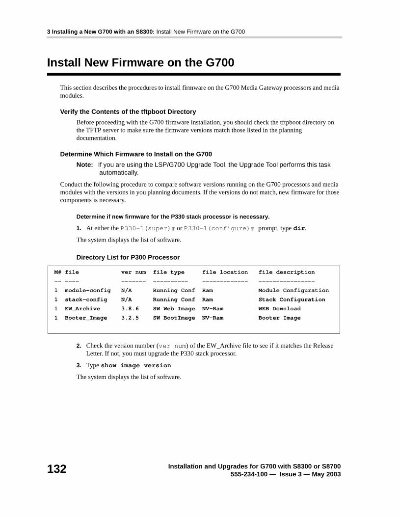
3 Installing a New G700 with an S8300: Install New Firmware on the G700
132 Installation and Upgrades for G700 with S8300 or S8700555-234-100 — Issue 3 — May 2003
Install New Firmware on the G700
This section describes the procedures to install firmware on the G700 Media Gateway processors and media modules.
Verify the Contents of the tftpboot Directory
Before proceeding with the G700 firmware installation, you should check the tftpboot directory on the TFTP server to make sure the firmware versions match those listed in the planning documentation.
Determine Which Firmware to Install on the G700
Note: If you are using the LSP/G700 Upgrade Tool, the Upgrade Tool performs this task automatically.
Conduct the following procedure to compare software versions running on the G700 processors and media modules with the versions in you planning documents. If the versions do not match, new firmware for those components is necessary.
Determine if new firmware for the P330 stack processor is necessary.
1. At either the P330-1(super)# or P330-1(configure)# prompt, type dir.
The system displays the list of software.
Directory List for P300 Processor
2. Check the version number (ver num) of the EW_Archive file to see if it matches the Release Letter. If not, you must upgrade the P330 stack processor.
3. Type show image version
The system displays the list of software.
M# file ver num file type file location file description
-- ---- ------- ---------- ------------- ----------------
1 module-config N/A Running Conf Ram Module Configuration
1 stack-config N/A Running Conf Ram Stack Configuration
1 EW_Archive 3.8.6 SW Web Image NV-Ram WEB Download
1 Booter_Image 3.2.5 SW BootImage NV-Ram Booter Image

3 Installing a New G700 with an S8300: Install New Firmware on the G700
Installation and Upgrades for G700 with S8300 or S8700555-234-100 — Issue 3 — May 2003
133
Show Image Version List for P330 Processor
4. Check the version number of the stack software image file in Band B to see if it matches the your planning document. If not, you must upgrade the P330 stack processor.
Determine if new firmware is required for the MGP, VoIP Module, and installed media modules.
1. Type session mgp
2. At the MG-001-1(super)# prompt, type show mg list_config
The system displays the list of software.
Show MG List_Config
3. Refer to the list to check the FW vintage number of the G700. In the TYPE column, find G700, then check the matching field in the FW VINTAGE column to see if it matches the vintage number in your planning forms. If not, you must install new firmware on the G700 Media Gateway. Also check if the release number in the FW VINTAGE column contains (A) or (B) to designate the software bank. If the list shows B, you will upgrade A. If the list shows A, you will upgrade B.
4. Refer to the VOIP FW column and row for slot V0 (same row occupied by the G700 information) to see if the number matches the VoIP firmware identified in your planning forms. If not, you must also upgrade the G700 Media Gateway motherboard VoIP module.
Note: The VoIP processor on the motherboard is upgraded using the same firmware image file as the VoIP media modules; for example, the file mm760v8.fdl is vintage #8.
5. Check the FW VINTAGE column for vintages of each of the installed Media Modules: MM710, MM711, MM712, MM720, and/or MM760 to see if they match the FW vintages in the planning forms. If not, you must upgrade them, as well.
Mod Module-Type Bank Version
------ ----------- ---- -------
3 Avaya G700 Media Gateway A 0.0.0
3 Avaya G700 Media Gateway B 3.9.0
eyp
SLOT TYPE CODE SUFFIX HW VINTAGE FW VINTAGE VOIP FW
---- ------ ----- ------ ---------- ---------- -------
V0 G700 DAF1 A 00 210(B) 2
V1 ICC S8300 A 72 00 N/A
V2 DCP MM712 A 2 52 N/A
V3 ANA MM711 A 2 12 N/A
V4 DS1 MM710 A 1 54 N/A

3 Installing a New G700 with an S8300: Install New Firmware on the G700
134 Installation and Upgrades for G700 with S8300 or S8700555-234-100 — Issue 3 — May 2003
Install New Firmware on the P330 Stack Processor
Install P330 stack processor firmware
1. From your S8300 telnet session, telnet back to the P330 stack processor:
Type telnet <xxx.xxx.xxx.xxx>, where <xxx.xxx.xxx.xxx> is the IP address of the P330 stack master processor on the customer’s LAN.
2. At the P330-1(configure)# prompt, type copy tftp SW_image <file> EW_archive <ew_file>
<tftp_server_address> <Module#>
where <file> is the full-path name for the image file with format and vintage number similar to viisa3_8_2.exe,
<ew_file> is the full-path name for the embedded web application file with format similar to p330Tweb.3.8.6.exe,
<tftp_server_ip_address> is the IP address of the TFTP server, and
<Module#> is the number, 1 through 10, of the media gateway in the stack. If there is only one G700 Media Gateway, the number is 1.
3. To verify that the download was successful when the prompt returns:
- type show image version <module #> and check the version number in the Version column for Bank B.
- type dir <module #> and check the version number in the ver num column for the EW_Archive file.
4. Type reset <module #>
Install New Firmware on the G700 Media Gateway Processor
Install MGP firmware
1. At the P330-1(configure)# prompt, type session mgp to reach the G700 Media Gateway processor.
2. Type configure at the MG-???-1(super)# prompt to enter configuration mode, which will change the prompt to MG-???-1(configure)#.
3. At the MG-???-1(configure)# prompt, type show mgp bootimage to determine which disk partition (bank) is in the Active Now column. You will update the bank that is not listed as Active Now. The system displays the following screen:

3 Installing a New G700 with an S8300: Install New Firmware on the G700
Installation and Upgrades for G700 with S8300 or S8700555-234-100 — Issue 3 — May 2003
135
Example: Show mgp bootimage
4. At the MG-???-1(configure)# prompt, type copy tftp mgp-image <bank> <filename> <tftp_server_ip_address>
to transfer the mgp image from the tftp server to the G700, where
<bank> is the bank that is not Active Now (Bank A in the example).
<filename> is the full path name of the mgp firmware image file, which begins with mgp and will be similar to the name mgp_8_0.bin.
<tftp_server_ip_address> is the IP address of the S8300. See the following example:
copy tftp mgp-image a mgp_8_0.bin 195.123.49.54.
The screen will show the progress.
5. Type set mgp bootimage <bank> where <bank> is the same letter you entered in the previous step.
6. At the MG-???-1(configure)# prompt, type reset mgp.
A system prompt asks to confirm the reset.
7. Select Yes at the dialog box that asks if you want to continue.
The G700 Media Gateway processor will reset. The LEDs on the G700 Media Gateway and the Media Modules will flash. These elements will each conduct a series of self-tests. When the LEDs on the Media Modules are extinguished and the active status LEDs on the G700 Media Gateway are on, the reset is complete.
8. Verify that the download was successful when the prompt returns. Type show mg list_config. The system displays the list of software.
FLASH MEMORY IMAGE VERSION
Bank A 109
Bank B 210
ACTIVE NOW ACTIVE AFTER REBOOT
Bank B Bank B

3 Installing a New G700 with an S8300: Install New Firmware on the G700
136 Installation and Upgrades for G700 with S8300 or S8700555-234-100 — Issue 3 — May 2003
Example: Show mg list_config
Install New Firmware on the Media Modules
For upgrades of active media modules, you need to take the media modules out of service before initiating the upgrade process. To do this, go to a SAT session on the primary controller and issue a busyout command.
Note: Skip this busyout procedure if the media modules are not in service; for example during an initial installation.
Busyout board (for active media modules)
1. Go to a SAT session on the primary controller and enter the command, busyout board vx where x is the slot number of the media module to be upgraded.
2. Verify the response, Command Successfully Completed.
3. Repeat for each media module to be upgraded.
Install media module firmware
1. Be sure that you have checked for the current vintage of the VoIP Module for the v0 slot (on the G700 motherboard) (see Determine Which Firmware to Install on the G700). This VoIP module does not occupy a physical position like other Media Modules.
2. At the P330-1(configure)# prompt, type session mgp.
3. At the MG-001-1(super)# prompt, type configure to change to the configuration mode.
4. Type copy tftp mm-image v<slot #> <filename mm> <tftp_server_ip_address>
where <slot #> is the slot of the specific media module as identified when you performed Determine Which Firmware to Install on the G700,
<filename mm> the full-path name of the media module firmware file in a format such mm712v58.fdl, and
<tftp_server_ip_address> is the ip address of the S8300.
SLOT TYPE CODE SUFFIX HW VINTAGE FW VINTAGE VOIP FW
---- ------ ----- ------ ---------- ---------- -------
V0 G700 DAF1 A 00 230(A) 67
V1 ICC S8300 A 72 00 N/A
V2 DCP MM712 A 2 58 N/A
V3 ANA MM711 A 2 57 N/A
V4 DS1 MM710 A 1 58 N/A

3 Installing a New G700 with an S8300: Install New Firmware on the G700
Installation and Upgrades for G700 with S8300 or S8700555-234-100 — Issue 3 — May 2003
137
Two or three minutes will be required for most upgrades. The VoIP Media Module upgrade takes approximately 5 minutes. Screen messages indicate when the transfer is complete.
5. After you have upgraded all the media modules, verify that the new versions are present. At the MG-???-1(configure)# prompt, type show mg list_config
The list of software appears
Show MG List_Config
6. In the TYPE column, find the particular media module (v1 through v4), then check the matching field in the FW VINTAGE column to see if it matches the planning documentation. Note that slot V1 can contain either a media module or the S8300 Media Server, which will show as Type "ICC".
7. Check the VOIP FW column and row for slot v0 to see if the number matches the VoIP firmware identified in the planning documentation.
8. Type reset <module #> where <module #> is the number of the G700 in the stack.
9. When the reset is finished, type show mm to verify the upgrade.
Release board (if media module was busied out)
1. When the upgrade procedure is complete, go to the SAT session and release the board:type release board vx where x is the slot number of the upgraded media module.
2. Verify the response, Command Successfully Completed.
Note: If you see the response, Board Not Inserted, this means that the media module is still rebooting. Wait on minute and repeat the release board command.
3. Repeat the release board command for each media module that was busied out.
Install New Firmware on Other G700 Media Gateways (Stack Configuration)
If the customer has multiple G700 media gateways connected in an IP stack, you can stay connected to the master G700/P330 and "session" over from the master P330 stack processor to the next G700 in the stack. If you are dialed in remotely, you should have automatically dialed in to the stack master. For a local installation, you should have plugged your laptop into the stack master P330, which you can identify by the LED panel on the upper left of each G700 or P330 device in the stack. The LEDs signal as follows:
• On the G700 Media Gateway: a lit MSTR LED indicates that this unit is the stack master.
• On the P330 device: a lit SYS LED indicates that this unit is the stack master.
SLOT TYPE CODE SUFFIX HW VINTAGE FW VINTAGE VOIP FW
---- ------ ----- ------ ---------- ---------- -------
V0 G700 DAF1 A 00 230(A) 67
V1 ICC S8300 A 72 00 N/A
V2 DCP MM712 A 2 58 N/A
V3 ANA MM711 A 2 57 N/A
V4 DS1 MM710 A 1 58 N/A

3 Installing a New G700 with an S8300: Install New Firmware on the G700
138 Installation and Upgrades for G700 with S8300 or S8700555-234-100 — Issue 3 — May 2003
The G700 and P330 at the bottom of the stack is module number 1, the next module up is number 2,. and so on. However, the stack master can be any module in the stack, depending on the actual model, the vintage firmware it runs, and whether the S8300 is inserted into it.
Note: You do not need to configure the other P330 stack processors in the stack. These will use the IP address and IP route of the master stack processor. However, you will need to check firmware on all devices of the other G700s in the stack, including the media gateways themselves, and update the firmware as required.
You may also use the "session stack" command to access other standalone P330 processors in the stack (those that are not part of a G700 unit).
1. At the MG-001-1(configure)# prompt, type session stack
The P330-1(configure)# prompt appears.
2. At the P330-1(configure)# prompt, type session <mod_num> mgp
<mod_num> is the next P330 processor in the stack. If you are currently logged in to the master stack processor, <mod_num> would be 2, for the second G700/P330 processor in the stack.
3. For other G700s in the stack, repeat the steps described previously to install firmware for the stack processor, MGP, and media modules.
Install New Firmware on Other G700 Media Gateways (Remote, No Stack Configuration)
If additional G700 media gateways are supported in the configuration, but they are not attached as a stack, then you must configure each G700, with all of its devices, including the P330 processors. Additionally, you must check firmware and update the firmware as required.

3 Installing a New G700 with an S8300: Administer Communication Manager
Installation and Upgrades for G700 with S8300 or S8700555-234-100 — Issue 3 — May 2003
139
Administer Communication Manager
Perform one of the following two administration procedures in this section:
• The Primary Controller is an S8300, or
• The Primary Controller is an S8700 (the S8300 Is an LSP)
The Primary Controller is an S8300
! CAUTION:This administration applies only to an S8300 that serves as the primary controller for the target G700. The S8300 primary controller can be in the target G700 or in another, possibly remote, G700. If the S8300 is an LSP, do not administer Communication Manager on it. Translations are automatically copied to the LSP from the S8300 primary controller.
If the primary controller is an S8700, skip this section and go to “The Primary Controller is an S8700 (the S8300 Is an LSP)” on page 145
This document covers only the administration of Communication Manager required for the G700 Media Gateway to communicate with the primary controller over a customer’s network. For the majority of administration required, see ‘‘Administrator’s Guide to Avaya™ Communication Manager, 555-233-506,’’ or ‘‘Administration for Network Connectivity for Avaya™ Communication Manager, 555-233-504.’’
In this section, you will use the SAT interface to:
• Assign Node Names for LSPs
• Define the IP Network Region
• Add a Media Gateway.
! CAUTION:Before continuing, be sure you have saved translations in Communication Manager.
Reset the System
1. Telnet to the S8300, log in, and open a SAT session (type sat or dsat).
2. At the SAT prompt, type reset system 4
The system reboots.
1. After the reboot is complete, telnet to the S8300, login, and open a SAT session.
Assign Node Names and IP Addresses for the LSPs
If the S8300 network configuration includes LSPs, they must be specifiied on the Node Names form.
Assign node names
1. At the S8300 SAT prompt, type change node-names ip to open the Node Names screen.

3 Installing a New G700 with an S8300: Administer Communication Manager
140 Installation and Upgrades for G700 with S8300 or S8700555-234-100 — Issue 3 — May 2003
2. Go to page 2
Example Node Names Screen.
3. Enter the name and IP addresses for the LSPs.
4. Press F3 (ENTER) when complete.
Administer Network Regions
Before assigning an IP network region to a G700, you must define network region on the IP Network Region form. After a network region is defined, you can assign it to the various network elements (servers, gateways, IP phones).
The information you need to do this should be provided in your planning documentation. Use the system defaults if the planning documentation does not specify otherwise.
For a G700 with an S8300 as primary controller, there will usually be one network region, defined as 1. The procedure below uses 1 for the network region number as an example but the procedure applies for any network region number from 1 to 250.
Define IP network region 1
! CAUTION:Defining IP network regions can be quite complex. For detailed information on the use and administration of IP network regions, see ‘‘Administration for Network Connectivity for Avaya™ Communication Manager, 555-233-504.’’
1. At the SAT prompt, type change ip-network-region 1.
The S8300 displays the IP Network Region screen.
change node-names ip Page 2 of 2
NODE NAMES
Name IP Address Name IP Address
default_________ 0__.0__.0__.0__ _______________ ___.___.___.___
node-10-lsp 192.168.1 _.50_ _______________ ___.___.___.___
node-11-lsp 192.168.1 _.51_ _______________ ___.___.___.___
__________ ___.___.___. _ _______________ ___.___.___.___
__________ ___.___.___. _ _______________ ___.___.___.___
__________ ___.___.___. _ _______________ ___.___.___.___

3 Installing a New G700 with an S8300: Administer Communication Manager
Installation and Upgrades for G700 with S8300 or S8700555-234-100 — Issue 3 — May 2003
141
IP Network Region Screen
2. If necessary, complete the fields as described in ‘‘Administration for Network Connectivity for Avaya™ Communication Manager, 555-233-504.’’
Note: It is strongly recommended to use the defaults in the screen. However, for the RTCP Enabled and RSVP Enabled fields, the entry should be n (no).
3. Press F3 (ENTER) to submit the screen.
Associate LSPs with Network Regions
If the primary controller has LSPs, you can associate each LSP with one or more network regions. In the event of a network failure, IP telephones assigned to a network region will register with an LSP associated with that region.
This procedure associates up to six LSPs with a network region.
Associate LSPs with a network region
1. On the IP Network Region screen, go to page 3.
change ip-network-region 1 Page 1 of 2
IP Network Region
Region: 1
Name:
Audio Parameters Direct IP-IP Audio Connections? n
Codec Set: 1 IP Audio Hairpinning? y
Location:
UDP Port Range RTCP Enabled? n
Min: 2048 RTCP Monitor Server Parameters
Max: 65535 Use Default Server Parameters? y
DiffServ/TOS Parameters
Call Control PHB Value: 34
VoIP Media PHB Value: 0
BBE PHB Value: 43 Resource Reservation Parameters
RSVP Enabled? n
802.1p/Q Enabled? N

3 Installing a New G700 with an S8300: Administer Communication Manager
142 Installation and Upgrades for G700 with S8300 or S8700555-234-100 — Issue 3 — May 2003
IP Network Region Screen, page 3
2. Enter the names of up to six LSPs to be associated with region 1. The LSP names must be the same as administered on the Node Names form.
3. Submit the form.
4. Repeat for each network region with which you want to associate LSPs.
change ip-network-region 1 Page 3 of 3
IP Network Region
LSP NAMES IN PRIORITY ORDER
1 node-10-LSP_____
2 ________________
3 ________________
4 ________________
5 ________________
6 ________________

3 Installing a New G700 with an S8300: Administer Communication Manager
Installation and Upgrades for G700 with S8300 or S8700555-234-100 — Issue 3 — May 2003
143
Administer IP Interfaces
This procedure assigns network region 1, as an example, to the S8300 Media Server.
Assign the network region to the S8300
1. At the SAT prompt, type change ip-interfaces.
The S8300 displays the IP Interfaces screen.
IP Interfaces Screen
2. The field Eth Port should indicate Y (yes). The Node Name should be the IP address of the S8300 Media Server.
Administer the LSP Form
If the primary controller has LSPs, you must enter the LSP node names on the LSP form to enable the LSPs to get translations updates from the primary controller. Once the LSPs are successfully entered on the LSP form, their status can be viewed with the display lsp command.
Note: The LSP node names must be administered on the node-names-ip form before they can be entered on the LSP form.
change ip-interfaces Page 1 of 6 SPE B
IP INTERFACES
Enable Net
Eth Pt Type Slot Code Sfx Node Name Subnet Mask Gateway Address Rgn
y PROC 135.122.49.55 255.255.0 .0 172.23 .23 .254 1
n 255.255.255.0 . . .
n 255.255.255.0 . . .
n 255.255.255.0 . . .
n 255.255.255.0 . . .
n 255.255.255.0 . . .
n 255.255.255.0 . . .
n 255.255.255.0 . . .
n 255.255.255.0 . . .
n 255.255.255.0 . . .
n 255.255.255.0 . . .
n 255.255.255.0 . . .
n 255.255.255.0 . . .
n 255.255.255.0 . . .
n 255.255.255.0 . . .

3 Installing a New G700 with an S8300: Administer Communication Manager
144 Installation and Upgrades for G700 with S8300 or S8700555-234-100 — Issue 3 — May 2003
Add LSP names to the LSP form
1. At the S8300 SAT prompt, type change lsp to open the LSP form.
LSP Screen
2. Enter the node name for each LSP supported by the primary controller and submit the form.
change lsp Page 1 of 16
LOCAL SURVIVABLE PROCESSOR
Number NAME IP Address Currently Translations
Available? Updated
1 node-10-LSP_ 192.168.1.50 y 14:21 5/4/2003
2 ____________ n
3 ____________ n
4 ____________ n
5 ____________ n
6 ____________ n
7 ____________ n
8 ____________ n
9 ____________ n
10 ____________ n
11 ____________ n
12 ____________ n
13 ____________ n
14 ____________ n
15 ____________ n
16 ____________ n

3 Installing a New G700 with an S8300: Administer Communication Manager
Installation and Upgrades for G700 with S8300 or S8700555-234-100 — Issue 3 — May 2003
145
The Primary Controller is an S8700(the S8300 Is an LSP)
! CAUTION:This administration applies only to an S8700 that serves as the primary controller for the target G700. Do not administer Communication Manager on the S8300 (LSP). Translations are automatically copied to the LSP from the S8700 primary controller after a save translations command or a data backup.
If the primary controller is an S8300, skip this section and go to “The Primary Controller is an S8300” on page 139.
Note: Some of the procedures in this section should have been completed previously as part of a normal S8700 installation.
This document covers only the administration of Communication Manager required for the G700 Media Gateway to communicate with the primary controller over a customer’s network. For the majority of required administration, see ‘‘Administrator’s Guide to Avaya™ Communication Manager, 555-233-506,’’ or ‘‘Administration for Network Connectivity for Avaya™ Communication Manager, 555-233-504.’’
In this section, you will use the SAT interface to:
• Assign Node Names
• Define the IP Network Region
• Add a Media Gateway
Note: For information on installing the CLAN boards on the S8700 port networks and complete information on installing an S8700 Media Server, see the Installation documentation on the ‘‘Avaya S8300 and S8700 Media Server Library CD, 555-233-825.’’
Assign Node Names and IP Addresses for the C-LANs and LSPs
Note: The CLAN boards must be TN799DP running version 5 or greater firmware. Be sure to check the firmware version for these boards on the S8700. For information on how to upgrade the firmware on the S8700, please see the section "Upgrade Firmware in Selected Port Cabinet Packs" in Upgrading the Avaya Media Server Configuration in the S8700 documentation portion of this documentation CD, ‘‘Avaya S8300 and S8700 Media Server Library CD, 555-233-325.’’
Assign node names and IP addresses
1. At the S8700 SAT prompt, type change node-names ip to open the Node Names screen.
2. Go to page 2

3 Installing a New G700 with an S8300: Administer Communication Manager
146 Installation and Upgrades for G700 with S8300 or S8700555-234-100 — Issue 3 — May 2003
Example Node Names Screen.
3. Enter the name and IP address for the C-LANs and LSPs.
4. Press F3 (ENTER) when complete.
Administer Network Regions
Before assigning an IP network region to a G700, you must define network region on the IP Network Region form. After a network region is defined, you can assign it to the various network elements (servers, gateways, IP phones).
The information you need to do this should be provided in your planning documentation. Use the system defaults if the planning documentation does not specify otherwise.
For a G700 with an S8300 LSP and an S8700 as the primary controller, there may be more than one network region, since there can be up to 250 G700 Media Gateways connected to the S8700 with thousands of telephones in the network. In this case, you define a network region for each CLAN board on the S8700 port networks, though they may also have the same network region.
The G700, in this case, may also share the same network region as the CLAN board(s). However, it may have a different network region because of the geographic distances of the connections between the G700 and the S8700. The G700 network region may also differ because of the nature of the endpoints connected to it.
Define IP network regions for the G700 and CLAN board(s)
! CAUTION:Defining IP network regions can be quite complex. For detailed information on the use and administration of IP network regions, see ‘‘Administration for Network Connectivity for Avaya™ Communication Manager, 555-233-504.’’
1. On the S8700 primary controller for the G700 Media Gateway, type change ip-network-region <network_region>, where the <network_region> is the region you will assign to the G700 Media Gateway. This region number may or may not match the network region of the S8700 CLAN boards.
The S8700 displays the IP Network Region screen.
change node-names ip Page 2 of 2
NODE NAMES
Name IP Address Name IP Address
default_________ 0__.0__.0__.0__ _______________ ___.___.___.___
node-1-clan __ 192.168.1 _.124 _______________ ___.___.___.___
node-2-clan 192.168.1 _.97_ _______________ ___.___.___.___
node-10-lsp 192.168.1 _.50_ _______________ ___.___.___.___
node-11-lsp 192.168.1 _.51_ _______________ ___.___.___.___
__________ ___.___.___. _ _______________ ___.___.___.___
__________ ___.___.___. _ _______________ ___.___.___.___
__________ ___.___.___. _ _______________ ___.___.___.___

3 Installing a New G700 with an S8300: Administer Communication Manager
Installation and Upgrades for G700 with S8300 or S8700555-234-100 — Issue 3 — May 2003
147
IP Network Region Screen
2. Complete the fields as described in ‘‘Administration for Network Connectivity for Avaya™ Communication Manager, 555-233-504.’’
Note: It is strongly recommended to use the defaults in the screen.
3. If the network region of the G700 (1 in this example) is different from that of the S8700 CLAN board(s), you must interconnect the two regions. Press NextPage to complete page 2, Inter Network Region Connection Management.
The S8700 displays page 2 of the IP Network Region screen. This screen shows a matrix of 250 network region numbers — 8 rows of 32 columns (only 26 columns are active in the last row). A region number is determined by the row and column cell position in the matrix. For example, region number 80 is the cell in the 3rd row (labled 65-96) and the 15th column (labled 5).
change ip-network-region 1 Page 1 of 3
IP Network Region
Region: 1
Name:
Audio Parameters Direct IP-IP Audio Connections? n
Codec Set: 2 IP Audio Hairpinning? y
Location:
UDP Port Range RTCP Enabled? n
Min: 2048 RTCP Monitor Server Parameters
Max: 65535 Use Default Server Parameters? y
DiffServ/TOS Parameters
Call Control PHB Value: 34
VoIP Media PHB Value: 0
BBE PHB Value: 43 Resource Reservation Parameters
RSVP Enabled? n
802.1p/Q Enabled? N

3 Installing a New G700 with an S8300: Administer Communication Manager
148 Installation and Upgrades for G700 with S8300 or S8700555-234-100 — Issue 3 — May 2003
IP Network Region Screen, Page 2
4. Type the number for the type of codec set (1–7) that the S8700 will use to interconnect the G700 and the C-LAN board(s) in the row/column position corresponding to the region of the C-LAN. In this example, the C-LAN is in region 80 and codec-set type 4 is to be used for the interconnection between region 1 and region 80. (In this example, codec type 2 is used for communication within region 1)
The SAT command, list ip-codec-set, lists the types of codecs available on this server.
For more detail about the Inter Network Region Connection Management form, see ‘‘Administration for Network Connectivity for Avaya™ Communication Manager, 555-233-504.’’
5. Press F3 (ENTER) when complete.
display ip-network-region 1 Page 2 of 3
Inter Network Region Connection Management
Region (Group Of 32)
1 2 3 4 5 6 7 8 9 0 1 2 3 4 5 6 7 8 9 0 1 2 3 4 5 6 7 8 9 0 1 2
001-032 2
033-064
065-096 4
097-128
129-160
161-192
193-224
225-250

3 Installing a New G700 with an S8300: Administer Communication Manager
Installation and Upgrades for G700 with S8300 or S8700555-234-100 — Issue 3 — May 2003
149
Assign LSPs to the Network Regions
If the primary controller has LSPs, you can assign the LSPs to network regions. In the event of a network failure, IP telephones assigned to a network region will register with the LSPs assigned to that region.
This procedure assigns up to six LSPs to a network region.
Assign LSPs to a network region
1. On the IP Network Region screen, go to page 3.
IP Network Region Screen, page 3
2. Enter the names of up to six LSPs to be assigned to region 1. The LSP names must be the same as administered on the Node Names form.
3. Submit the form.
4. Repeat for each network region to which you want to assign LSPs.
change ip-network-region 1 Page 3 of 3
IP Network Region
LSP NAMES IN PRIORITY ORDER
1 node-10-LSP______
2 ________________
3 ________________
4 ________________
5 ________________
6 ________________

3 Installing a New G700 with an S8300: Administer Communication Manager
150 Installation and Upgrades for G700 with S8300 or S8700555-234-100 — Issue 3 — May 2003
Administer IP Interfaces
Define the IP interfaces of the S8700 port network CLAN boards
Note: This should have already been established as a part of normal S8700 installation.
1. Type change ip-interfaces to open the IP Interfaces screen.
IP Interfaces Screen
2. Complete the fields as described the in the following table.
change ip-interfaces Page 1 of 6 SPE B
IP INTERFACES
Enable Net
Eth Pt Type Slot Code Sfx Node Name Subnet Mask Gateway Address Rgn
y C-LAN 02C18 TN799 C st7clan 255.255.0 .0 172.23 .23 .254 80
n MEDPRO 02C08 TN802 B st7_mp1 255.255.255.0 192.168.22 .254 6
y MEDPRO 02C11 TN2302 st7_prowler1 255.255.0 .0 172.23 .23 .254 7
y C-LAN 02B17 TN799 C st7clan3 255.255.0 .0 172.23 .23 .254 6
y C-LAN 01A06 TN799 C st7clan4 255.255.0 .0 172.23 .23 .254 80
y MEDPRO 02C13 TN2302 st7_prowler6 255.255.0 .0 172.23 .23 .254 1
y MEDPRO 02C15 TN2302 st7_prowler7 255.255.0 .0 172.23 .23 .254 80
n MEDPRO 02C16 TN2302 st7_prowler8 255.255.0 .0 172.23 .23 .254 80
Field Conditions/Comments
Enable Eth Pt The Ethernet port must be enabled (y) before it can be used. The port must be disabled (n) before changes can be made to its attributes on this screen.
Type Either C-LAN.
Slot The slot location for the circuit pack.
Code Display only. This field is automatically populated with TN799 for C-LAN.
Sfx Display only. This field is automatically populated.
Node name The unique node name for the IP interface. The node name here must already be administered on the Node Names screen.
1 of 2

3 Installing a New G700 with an S8300: Administer Communication Manager
Installation and Upgrades for G700 with S8300 or S8700555-234-100 — Issue 3 — May 2003
151
3. Close the screen.
Subnet Mask The subnet mask associated with the IP address for this IP interface.
For more information on IP addresses and subnetting, see “Administration for Network Connectivity for Avaya™ Communication Manager, 555-233-504”.
Gateway Addr The address of a network node that serves as the default gateway for the IP interface.
Net Rgn The region number for this IP interface.
Field Conditions/Comments
2 of 2

3 Installing a New G700 with an S8300: Administer Communication Manager
152 Installation and Upgrades for G700 with S8300 or S8700555-234-100 — Issue 3 — May 2003
Administer the LSP Form
If the primary server has LSPs, you must enter the LSP node names on the LSP form to enable the LSPs to get translations updates from the primary controller. Once the LSPs are successfully entered on the LSP form, their status can be viewed with the display lsp command.
Note: The LSP node names must be administered on the node-names-ip form before they can be entered on the LSP form.
Add LSP names to the LSP form
1. At the SAT prompt, type change lsp to open the LSP form.
LSP Screen
2. Enter the node name for each LSP supported by the primary controller and submit the form.
change lsp Page 1 of 16
LOCAL SURVIVABLE PROCESSOR
Number NAME IP Address Currently Translations
Available? Updated
1 node-10-LSP__ 192.168.1.51 y 13:06 5/4/2003
2 ____________ n
3 ____________ n
4 ____________ n
5 ____________ n
6 ____________ n
7 ____________ n
8 ____________ n
9 ____________ n
10 ____________ n
11 ____________ n
12 ____________ n
13 ____________ n
14 ____________ n
15 ____________ n
16 ____________ n

3 Installing a New G700 with an S8300: Administer Communication Manager
Installation and Upgrades for G700 with S8300 or S8700555-234-100 — Issue 3 — May 2003
153
Administer the Media Gateway
To perform the procedures in this section, telnet to the primary controller, log in, and open a SAT session.
! CAUTION:Before administering a media gateway, make sure that the gateway has been fully configured.
Add Media Gateway
1. At the SAT prompt, type add media-gateway <number>where <number> is the gateway number from 1 to n . (n is 50 for an S8300 and 250 for an S8700).
The S8300 displays the Media Gateway screen.
Add Media Gateway Screen
2. Complete the Name field with the hostname assigned to the G700 Media Gateway.
3. Complete the Identifier field with the serial number of the G700 Media Gateway. You can obtain the serial number by typing the show system command at the MGP command line.
! CAUTION:Be sure the serial number for the G700 Media Gateway you enter in this procedure matches exactly the serial number displayed in the show system command. The serial number is case-sensitive, and if entered incorrectly, will prevent the S8300 Media Server from communicating with the G700 Media Gateway.
change media-gateway 1 Page 1 of 1
MEDIA GATEWAY
Number: 1
Name: Swainsons Identifier: 012X06230551
IP Address: MAC Address:
Network Region: 1 Location: 1
Site Data: Registered? n
Slot Module Type
V1:
V2:
V3:
V4:
V8:
V9:

3 Installing a New G700 with an S8300: Administer Communication Manager
154 Installation and Upgrades for G700 with S8300 or S8700555-234-100 — Issue 3 — May 2003
4. Complete the Network Region field with the value supplied in the planning documentation.
5. If specifically requested by the customer or your planning documents, type gateway-announcements in the V9 field. This field allows you to enable announcements on the G700 Media Gateway. V9 is a virtual slot. There is no announcement board associated with it. The announcements for the G700 are available in the G700 firmware and are administered in the same way as announcements on the TN2301 circuit pack used on S8700 port networks.
If there are multiple G700 Media Gateways sharing announcements, then enable announcements on the G700 whose trunks will receive the announcements most often.
6. Press F3 (ENTER) to save your changes.
If properly administered, the G700 should register with the primary controller within 1–2 minutes. The IP Address, MAC Address, and Module Type fields are populated automatically after the G700 Media Gateway registers with the server.
7. Type change media-gateway to view the Media Gateway form.
Media Gateway Screen (After Registration with Primary Controller)
The media modules installed in the G700 are listed next to their slot numbers.
To verify that a G700 Media Gateway has been successfully added:
Verify Changes
1. At the SAT prompt, type list media-gateway.
change media-gateway 1 Page 1 of 1
MEDIA GATEWAY
Number: 1
Name: Swainsons Identifier: 012X06230551
IP Address: 145. 9. 73.101 MAC Address: 00:04:0d:02:05;0a
Network Region: 1 Location: 1
Site Data: Registered? y
Slot Module Type
V1: icc
V2: ds1
V3: analog
V4: dcp
V8: messaging-analog
V9:

3 Installing a New G700 with an S8300: Administer Communication Manager
Installation and Upgrades for G700 with S8300 or S8700555-234-100 — Issue 3 — May 2003
155
List Media-Gateway Screen
2. Verify that the G700 Media Gateway has registered.
The y in the registered field signifies that the G700 Media Gateway has registered. If the G700 should become unregistered, the y will become an n, but the IP address will remain assigned to the G700 Media Gateway. If the G700 has never been registered, the IP Address field will be blank.
If the G700 fails to register, two common causes might be:
- The serial number added as the identifier for the G700 is wrong. To check, log back into the G700 gateway and type show system. Check the serial number that appears.
- There is no IP connection between the G700 and the S8300. To check, type show mgc and then ping mgp <controller_address>.
Enable Announcements, If Necessary
1. Only if specifically requested by the customer or your planning documents, at the SAT prompt, type enable announcement-board <gateway_number> V9, where <gateway_number> is the number of the G700 Media Gateway you just added and V9 is the virtual slot (for example, 2V9 means Media Gateway number 2, slot V9.
2. Press ENTER to enable announcements.
The system displays the message Command successfully completed.
Save Communication Manager Translations
Save translations again after all Communication Manager administration is complete.
- At the SAT prompt, type save translations.
list media-gateway
MEDIA-GATEWAY REPORT
Number Name Identifier IP Address Registered?
1 LabA 01DR07128730 135.177.49.57 y
2 Data MG2 02DR01130356 135.177.49.90 n

3 Installing a New G700 with an S8300: Considerations for IP Phones Supported by a Local Survivable
Processor
156 Installation and Upgrades for G700 with S8300 or S8700555-234-100 — Issue 3 — May 2003
Considerations for IP Phones Supported by a Local Survivable Processor
A DHCP server assigns IP addresses to IP endpoints dynamically. Avaya IP phones perform a DHCP discover request to receive an IP address, as well as receive parameters necessary to function correctly. These parameters include the location of the call control server, the location of the TFTP server, as well as the directory on the TFTP server from which the phone receives its upgrades.
When preparing a DHCP server to work with Avaya IP phones, there is an option that must be administered to allow the Avaya phone to receive the DHCP offer. This option is “site-specific-option-number” (sson) 176. Different DHCP servers allow for this administration in different ways, but the sson option must be mapped to 176. Then the option can be set up to send the information desired to the Avaya phones for the intended activity.
The sson option sends a string that includes the IP address of the Avaya Call Controller with which the phone will register (“MCIPADD=www.xxx.yyy.zzz”). In an S8700 system, this is a CLAN address; in an S8300 system, this is the IP address of the S8300. Multiple addresses can be administered to allow for LSP failover. The second address in the MCIPADD list may be an IP address for a second S8700 CLAN board or an LSP. If a second CLAN board is used, then the third address must be the LSP, and any subsequent addresses should be alternate LSPs. Local LSPs should appear first in the list, with remote LSPs later in the list as possible back ups.
If an IP phone looses its connection to the primary controller, it will try to register with an LSP associated with its network region (as defined on page 3 of the IP Network Region form). However, if the phone resets, it looses this information and goes to the DHCP server for a controller. If the only controller in the MCIPADD list is the primary controller, and if the connection to the primary controller is down, the phone cannot register. Having an LSP in the MCIPADD list gives the IP phones an alternate controller in this situation.
Note: It is strongly recommended that at least one LSP be administered in the MCIPADD list.
Also included in the sson option string is the “MCPORT=1719”. This is the port the phone will listen on for signalling traffic to the call controller. Next is the tftp server field. This field indicates to the phone where it is to receive firmware updates, along with the tftp directory field.
All phones for which the DHCP server has an LSP as the second address in the MCIPADD list should be administered to be in the same network region. Or, if administered to be in different network regions, the network regions involved should be interconnected. Use the ip-network-map form on the primary controller to put the IP phones in the same network region. On the ip-network-map form, a range of IP addresses (or a subnet) can be specified to be in a single network region. Enter the IP address range, or subnet, that contains the IP addresses of the IP phones and enter the desired network region number for that address range. The same address range or subnet must then be administered on the DHCP server. If it is not desired that all the phones be in the same network region, the form “ip-network-region #” should be used to interconnect all the network regions that contain those phones.
Transition of Control from Primary Controller to LSP
When the network connection between the G700 and the S8700 goes down, control of endpoints connected to the G700 goes to the next point in the primary controller list, which will be either a second CLAN board or the LSP. At this point, the S8700 alarms to notify the customer and services

3 Installing a New G700 with an S8300: Set Up SNMP Alarming on the G700
Installation and Upgrades for G700 with S8300 or S8700555-234-100 — Issue 3 — May 2003
157
personnel that the network connection between the S8700 and G700 has problems. If control passes to the LSP, the LSP’s license allows it to support the G700 endpoints for up to 10 days, within which the network problems should be resolved.
The customer must pass control back to the S8700 manually, by selecting Shutdown this server from the S8300 web page (includes selecting the option to restart after shutdown), or a technician must run reset system 4 from the Linux command line. When the system reboots, the G700 and its endpoints reregister with the primary controller, in this case the S8700.
Set Up SNMP Alarming on the G700
Setting up SNMP alarm reporting involves two main tasks:
• Configuring the primary server to report alarms to a services support agency
• Configuring the G700 Media Gateway to send its traps to a network management system (NMS), which can be the primary server (S8300/S8700).
The primary server may be either an S8300 Media Server or an S8700 Media Server. The server supports two methods for reporting alarms. Either, both, or no alarm-reporting method may be used at a given site.
• OSS Method. The server's software applications and hardware devices under its control can generate Operations Support System (OSS) alarms. These alarms are recorded in the server logs, and may be reported to Avaya's Initialization and Administration System (INADS) or another services support agency over the server's modem interface.
To activate OSS alarm notification: The server requires a USB connection to a modem that is connected to an analog line. The modem must be configured using the Web Interface, in the Set Modem Interface screen, and enabled to send and receive calls using the Enable/Disable Modem screen. Configuration of the OSS alarming method can only be done using Linux shell commands.
• SNMP Method. SNMP traps may be sent in User Datagram Protocol (UDP) to a corporate network management system (NMS) using the Configure Trap Destinations screen. The OSS and SNMP alarm-notification methods operate independently of each other; either or both may be used. Currently, the following NMSs are supported:
- Avaya Fault and Performance Manager, as a standalone application, or integrated within
- Avaya MultiService™ Network Manager
- HP Openview
To activate SNMP alarm notification: On the server Web Interface, use the Configure Trap Destinations screen to set up SNMP destinations in the corporate NMS.
Add INADS phone numbers and Enable alarms to INADS
The following procedure using the primary server’s Linux shell commands administers the dial-out modem to send alarms in the OSS method. In this example, the primary server is an S8300, and the services support agency is Avaya’s Initialization and Administration System (INADS).
Perform this task after all Communication Manager administration is complete.

3 Installing a New G700 with an S8300: Set Up SNMP Alarming on the G700
158 Installation and Upgrades for G700 with S8300 or S8700555-234-100 — Issue 3 — May 2003
Note: Do these steps only if the S8300 is the primary controller and the customer has a maintenance contract with Avaya. Use the information you acquired from the ART tool (see Run the ART Tool for the INADS IP Address, if Necessary). Also, a USB modem must have already been installed.
1. With a direct connection to the S8300 Services port, start a Telnet session and log in as craft.
1 . At the prompt, type almcall -f INADS phone number -s <second-number> and press Enter.
2 . At the prompt, type almenable -d b -s y and press Enter.
3 . Type almenable and press Enter to verify that the alarms are enabled.
4 . Log off.
Configure an SNMP Community String for Traps
Configuring the G700 Media Gateway to send SNMP traps to the primary server can be accomplished by two commands:
• P330 stack processor CLI command set snmp community trap [community string]
• Media Gateway Processor (MGP) CLI command set snmp trap <IP address> enable
SNMP requires community strings to be used for each SNMP ’request’. You can set only three community strings on the G700 — one each for read requests, write requests, and traps. The command for traps is set snmp community trap [community string].
1. Telnet to the P330 stack processor.
2. Log in as root.
3. At the P330-1(super)# prompt, type set snmp community trap [community string] and press Enter.
4. Type exit
Configure the Destination for G700 SNMP Traps
Events occurring on the G700 cause SNMP traps to be generated. The G700 MGP can be configured to send SNMP traps to any network management system (NMS) in the network, including the primary server (S8300/S8700). The MGP CLI set snmp trap command is the way to configure the NMS network element that will receive those traps.
The command syntax is:
set SNMP trap <IP address> {enable|disable}[{all|power|temp|app|module|config|voice|operations}]
where <IP address> is the IP address of the NMS trap receiver that will be receiving the traps from the G700, and
[{all|power|temp|app|module|config|voice|operations}] indicates the groups whose traps will be sent to the specified receiver. If no keywords follow the IP address entry, then ’all’ traps will be enabled for the specified receiver.
If ’enable’ or ’disable’ is used without a trap designation keyword, then ’all’ traps is assumed. Up to ten trap receivers can be configured.

3 Installing a New G700 with an S8300: Complete the Installation of S8300 (if the Primary Controller)
Installation and Upgrades for G700 with S8300 or S8700555-234-100 — Issue 3 — May 2003
159
1. At the P330-1(super)# prompt, type session mgp
2. At the mg-xxx-n(super-user)# prompt, type configure and press Enter.
3. At the mg-xxx-n(configure)# prompt, type set snmp trap <IP address> enable and press Enter.
4. Type exit
Complete the Installation of S8300(if the Primary Controller)
Consult the planning documentation to obtain the necessary information to complete the installation. Part of the final process will be to:
• Connect and administer test endpoints
• Test the endpoints
• Administer Communication Manager for trunks, features, networking, or other items required by the customer.
• Complete the electrical installation
• Enable adjunct systems
Register the system
Follow the existing process and procedures to register the S8300.
Back up the System
1. Make sure you have the IP address of the customer’s FTP backup server.
2. On the S8300 main menu, select Backup Now.
The system displays the Backup Now screen.
3. Select the type of data you want to back up by selecting the appropriate data set.
4. Select a backup method, normally FTP, to indicate the destination to which the system sends the backup data.
5. Complete the following fields:
User name. You must enter a valid user name to enable the media server to log in to the FTP server. If you want to use the anonymous account, type "anonymous" in this field. If you do not want to use the anonymous account, type the actual user name in this field.
Password. You must enter a password that is valid for the user name you entered. If you are using anonymous as the user name, you must use your email address as the password. However, the FTP site may have a different convention.

3 Installing a New G700 with an S8300: Complete the Installation Process
160 Installation and Upgrades for G700 with S8300 or S8700555-234-100 — Issue 3 — May 2003
Host name. Enter the DNS name or IP address of the FTP server to which the backup data is sent. To enter an IP address, use the dotted decimal notation (for example, 192.11.13.6).
Directory. Enter the directory on the corporate repository to which you want to copy the backup file. When you enter a forward slash (/) in the directory field, the system copies the backup file to the default directory. The default directory for backup data on the FTP server is /var/home/ftp. If you do not want to use the default directory, you must enter the path name for the directory.
6. Click Start Backup.
The system displays the results of your backup procedure on the Backup Now results screen.
Complete the Installation Process
Consult the planning documentation to obtain the necessary information to complete the installation. Part of the final process will be to:
• Connect and administer test endpoints.
• Test the endpoints.
• Complete the electrical installation
• Enable adjunct systems
This completes the installation of the G700 Media Gateway with and S8300 Media Server.

Installation and Upgrades for G700 with S8300 or S8700555-234-100 — Issue 3 — May 2003 161
4 Installing a New G700 without an S8300
This chapter covers the procedures to install the firmware on an new AvayaTM G700 Media Gateway without an AvayaTM S8300 Media Server. The G700 is controlled by an external primary server running AvayaTM Communication Manger. The primary server can be either an AvayaTM S8700 Media Server or an S8300 residing in another G700.
Note: Procedures to install or upgrade an S8700 Media Server are not covered in this document. See AvayaTM S8300 and S8700 Media Server Library, which is on the Avaya Support website (http://www.avaya.com/support) or on the CD, 555-233-825.
Note: If you are using the Avaya Gateway Installation Wizard (GIW), the GIW performs these tasks automatically: Assign the IP Addresses of the G700 Media Gateway Components, Set up the Controller List for the G700 Media Gateway, Check for IP Connections, and Set the LSP Transition Points sections. However, the GIW does not configure an X330 Expansion module. This task you must still perform as described in this document.

4 Installing a New G700 without an S8300: Installation Overview
162 Installation and Upgrades for G700 with S8300 or S8700555-234-100 — Issue 3 — May 2003
Installation Overview
G700 components
A P330 stack processor is built into the G700 Media Gateway. (This processor is also known as the Layer 2 switching processor). The G700 also contains an MGP processor, a VoIP processor, up to four media modules, and possibly an expansion module. Installing the firmware for one or more of these processors and/or media modules is a required part of most new installations.
Firmware files
You should obtain the firmware files for the G700 before going on-site. You can obtain the firmware files in bundled form on a CD or you can go to the Avaya Support website and download the individual firmware files onto your services laptop.
TFTP Server
To install firmware on a G700 without an S8300 or LSP, you must first copy the firmware files to an external TFTP server on the customer LAN. The TFTP server can be a customer computer or it can be set up on your services laptop.
Initial Access to the G700
Before the P330 stack processor is configured with an IP address, the only way to access it is with a direct connection from your laptop to the Console port on the G700. With this connection, you can assign the IP addresses to the G700 processors, which can then be accessed over the customer LAN.
Access to the S8300 and G700
You can access the S8300 and G700 in several ways with either a direct connection or LAN connection.
Note: Before the LSP/G700 Upgrade Tool can be used to upgrade software on an LSP or firmware on a G700, as summarized below, the LSP must be administered on the primary controller.
Direct connection to target S8300
If you are at the location of the target S8300 (primary or LSP), you can connect directly to the S8300 Services port and:
1 . Upgrade the S8300 software by
- Opening the Web interface and using the Avaya Installation Wizard
- Or, opening the Web interface and using the main menu
2 . Upgrade the G700 firmware by
- Opening the Web interface and using the LSP/G700 Upgrade Tool
- Or, telnet to the S8300 and then telnet to the P330 stack processor
Direct connection to the remote primary server (S8300 or S8700)
In this case, the target S8300 is an LSP. If you are at the remote location of the primary server, you can connect directly to the server’s Services port and:

4 Installing a New G700 without an S8300: Installation Overview
Installation and Upgrades for G700 with S8300 or S8700555-234-100 — Issue 3 — May 2003
163
1 . Upgrade the S8300 (LSP) software by
- Opening the Web interface and using the LSP/G700 Upgrade Tool
2 . Upgrade the G700 firmware by
- Opening the Web interface and using the LSP/G700 Upgrade Tool
- Or, telnet to the primary server and then telnet to the P330 stack processor and perform the installation commands
For direct connections, the TFTP server must be on the Customer LAN, not on your laptop.
LAN connections
If you can connect to the customer’s LAN, you can:
1 . Upgrade the S8300 software by
- Opening the Web interface on the S8300 and using the Avaya Installation Wizard
- Or, Opening the Web interface on the S8300 and using the main menu
2 . Upgrade the G700 firmware by
- Opening the Web interface on the primary server and using the LSP/G700 Upgrade Tool
- Or, telnet to the P330 stack processor and perform the installation commands
For LAN connections the TFTP server can be your laptop or a customer computer on the LAN.
See "Connection and Login Methods" in Chapter 1 for details on how to connect and log into the G700.

4 Installing a New G700 without an S8300: Before Going to the Customer Site
164 Installation and Upgrades for G700 with S8300 or S8700555-234-100 — Issue 3 — May 2003
Before Going to the Customer Site
The procedures in this section should be completed before going to the customer site or before starting a remote installation.
Get Planning Forms from the Project Manager
The project manager should provide you with forms that contain all the information needed to prepare for this installation. The information primarily consists of IP addresses, subnet mask addresses, logins, passwords, people to contact, the type of system, and equipment you need to install.
Verify that the information provided by the project manager includes all the information requested in your planning forms.
Get the Serial Number of the G700, if Necessary
For an upgrade of an existing G700, the existing license file can usually be reused.
For a new installation, you need the serial number of the G700 Media Gateway in order to complete the creation of the customer’s license file on the rfa.avaya.com web site. To get this number, look for the serial number sticker on the back of the G700 chassis. If the unit is delivered directly to the customer and you will not have phone or LAN line access from the customer site to access the rfa.avaya.com web site, this task will require a preliminary trip to the customer site.
However, if the customer is adding feature functionality (for example, adding BRI trunks), you will need the serial number of the G700. To get this number, ask the customer’s administrator to log in to the S8300 web page and select View License Status from the main menu to display the serial number.
Set Up the TFTP Server on Your Laptop or on a Customer PC, if Necessary
A tar.gz file, which you obtain from a CD-ROM or a website, contains new G700 software. To load this software on a G700 Media Gateway, you must place this tar.gz file either on your laptop or on a PC connected to the customer’s LAN. Later, you will log in to the G700 and use its TFTP capability to pull the new software from your laptop or the customer’s PC. As a result, either the customer must configure a TFTP server on a PC connected to the customer’s LAN or you, the installer, must set up your laptop as a TFTP server and later connect it to the customer’s LAN.
Note: A Linux or Unix TFTP server should be used only if the customer already has an existing one. In these cases, you download the tar.gz file to your laptop and give it to the customer for proper placement and execution.
1. On the hard drive of your laptop or the customer’s PC, create a directory into which you will load the G700 software. It is recommended that you create a directory called C:\tftp.
2. Connect to the LAN using a browser on your laptop or the customer’s PC and access http:// www.avaya.com/support on the Internet.

4 Installing a New G700 without an S8300: Before Going to the Customer Site
Installation and Upgrades for G700 with S8300 or S8700555-234-100 — Issue 3 — May 2003
165
3. At the Avaya support site, select the following sequence of menu options:
4. Double-click on one of the links listed with "TFTP Server"; for example, 4630 IP Telephone R 1.73 and TFTP Server.
5. Scroll to bottom of page to find the TFTP Server Application file, iptel_avaya_tftp.exe.
6. Double-click on the program and download it to your laptop or the customer PC that will serve as the TFTP server. Remember where the iptel_avaya_tftp.exe file is installed on your laptop or PC and write it down.
You may also wish to download and view or print the file iptel.pdf, which provides instructions on installing the iptel_avaya_tftp.exe for Windows servers.
7. After downloading the iptel_avaya_tftp.exe file to the PC, double-click it and follow instructions to install it. By default, the installation program creates the directory, C:\Program Files\Walusoft\TFTPSuite that contains the application files.
8. When the file has been installed, go to the directory where the software was installed and double-click the file tftpserver32.exe to open the program.
The TFTP Server window appears. It reflects the IP address of the PC in the upper border, plus port 69.
9. Enable the TFTP server as follows:
- Click on System from menu bar and select setup.
The server option window appears.
- Select the Outbound tab, and enter C:\tftp - (or your alternate tftp location) for the outbound file path.
- Under Options tab, enter 69 in the Use Port field (default).
- Select No Incoming (default). However, if you wish to copy files as a backup prior to performing an upgrade of software, leave this field unchecked.
- Select the Inbound tab, and enter C:\tftp (or your alternate tftp location) for the inbound file path.
- Click OK.
> Software Downloads
>4600 Series IP Telephones
> Telephones and End User Devices
> Software & Firmware Downloads

4 Installing a New G700 without an S8300: Before Going to the Customer Site
166 Installation and Upgrades for G700 with S8300 or S8700555-234-100 — Issue 3 — May 2003
Download G700 Firmware Files to Your TFTP Directory
To install new firmware for the G700 processors and the media modules, you first need to move the new firmware files to a directory on the TFTP server. The installation program reads the new firmware files from this directory on the TFTP server.
Perform one of the two procedures in this section, depending on whether you have a bundled tar.gz file on a CD or wish to download individual firmware files from the Avaya Support website.
For a Bundled Firmware File
Note: Your laptop (or the customer’s PC) must have WinZip or other file zipping software for this procedure.
Copy the tar.gz File from CD-ROM to Your TFTP Directory and Unzip It
1. Insert the G700 software CD into your laptop or PC CD-ROM drive.
2. Use Windows File Explorer or another file management program to access the files on the CD-ROM drive.
3. Copy the tar.gz file (G700-11.3-0009.0.tar.gz or similar identifier) to the C:\tftp directory (or your alternate tftp location).
4. Use winZIP or another zipfile tool to unzip the file. You may need to unzip an additional tar.gz file embedded in the original file. You should continue to unzip tar.gz files until you see listed files with extensions as shown in the table "Firmware File Formats" below.
For Individual Firmware Files
Download the Firmware Files from the Web to Your TFTP Directory
Note: The sequence of links on the website may be somewhat different than described here.
1. Access the www.avaya.com/support website.
2. At the Avaya support site, click on Software & Firmware Downloads and then click on the following sequence:
> G700 Media Gateway & S8300 Media Server.
> Firmware Downloads
> G700 Firmware Downloads.
The system displays a list of firmware files.
3. Locate the file names that match the files listed in your planning documentation. The file names will approximate those listed in the following table:

4 Installing a New G700 without an S8300: Before Going to the Customer Site
Installation and Upgrades for G700 with S8300 or S8700555-234-100 — Issue 3 — May 2003
167
Firmware File Formats
4. Double-click the file name.
The system displays a File Download window.
5. Click on Save this file to disk.
6. Save the file to the C:\tftp directory (or your alternate tftp location).
7. Use Winzip or another zip file tool to unzip the file, if necessary.
Component Firmware Version Format
Example
P330 Stack Processor viisa<version id> viisa3_12_1.exe
P330 Stack Processor p330<version id> p330Tweb.3.8.6.exe
G700 Media Gateway mgp<version id> mgp_8_0.bin
VoIP Media Module and Motherboard VoIP
mm760<version id> mm760v3.fdl
DCP Media Module mm712<version id> mm712v2.fdl
Analog Port/Trunk Media Module
mm711<version id> mm711v4.fdl
E1/T1 Media Module mm710<version id> mm710v3.fdl
BRI Media Module mm720<version id> mm720v2.fdl

4 Installing a New G700 without an S8300: Configure the G700
168 Installation and Upgrades for G700 with S8300 or S8700555-234-100 — Issue 3 — May 2003
Configure the G700
Note: If you are using the Avaya Gateway Installation Wizard (GIW), the GIW performs tasks automatically in the Assign the IP Addresses of the G700 Media Gateway Components, Set up the Controller List for the G700 Media Gateway, Check for IP Connections, and Set the LSP Transition Points sections. However, the GIW does not configure an X330 Expansion module. This task you must still perform as described in this document.
For a new installation of a G700 Media Gateway, you must complete the following configuration tasks:
• Assign IP addresses to the G700 processors
• Assign IP routes for the gateway
• Set up the controller list
Assign the IP Addresses of the G700 Media Gateway Components
Note: If you are using the Avaya Gateway Installation Wizard (GIW), the GIW performs this task automatically.
This section describes how to assign the IP addresses and IP routes to the G700 Media Gateway and its components. The IP addresses should be available to you on the IP Addressing Planning Form. The command arguments you will be supplying include:
vlan –Virtual Local Area Network: a defined network segment that allows users on that segment to have priority services in sharing information with each other.
If the network is not using VLANs, the VLAN should be 1. Otherwise, use the VLAN numbers indicated in your planning forms. The G700 Media Gateway should be assigned the same VLAN as the VLAN to which the Ethernet ports are connected. The P330 stack processor might or might not be assigned to the customer’s network management VLAN.
IP address –the unique identifier assigned to an entity on the customer LAN
netmask –the subnet mask for the customer’s LAN segment
destination –distant networks that the IP route command needs to send packets to. Usually generalized to 0.0.0.0 for networks other than the local segment.
default gateway –the gateway the ip route command specifies to get to the distant networks

4 Installing a New G700 without an S8300: Configure the G700
Installation and Upgrades for G700 with S8300 or S8700555-234-100 — Issue 3 — May 2003
169
Access the P330 stack processor
1. Set up a direct connection to the G700 Console (serial) port and access the P330 stack processor using Hyperterm (or similar terminal emulation application).
2. Login as root.
Assign the IP address to the P330 stack processor
1. At the P330-1(configure)# prompt, typeset interface inband <vlan> <ip_address> <netmask> to assign an IP address to the P330 stack processor.<vlan> is the vlan number, usually 1, to be established on the S8300 for the G700 Media Gateways. The <ip_address> <netmask> is the assigned addresses for the P330 stack processor.
2. Type reset and press Enter to reset the stack.
3. Select Yes at the dialog box that asks if you want to continue.
All LEDs will flash. As the unit powers up, self-tests will be run. When the G700 mpg or P330 stack processor has reset, login again to continue.
4. Login at the Welcome to P330 menu.
The prompt P330-1(super)# appears.
5. Type configure to obtain the P330-1(configure)# prompt.
Establish the IP Routing for the Stack
1. Type show interface inband to verify that the Avaya P330 stack server (Layer 2 Switching Processor) has the correct address.
2. Type set ip route 0.0.0.0 <default-gateway> to set the destination and gateway IP addresses. You will find these addresses in the planning documentation. <default-gateway> is the IP address of the customer’s network gateway.
3. Press Enter to save the destination and gateway IP addresses.
4. Type show ip route.
The route net and route host tables appear. Verify that the information is correct.
Check the serial number of the G700 Media Gateway processor
After you have configured the P330 stack processor, you will assign an IP address to the G700 Media Gateway Processor (MGP). Your first step is to check the serial number of the MGP.
1. At the P330-1(configure)# prompt, type session mgp.
2. At the MG-???-1(super)# prompt, type show system to list various attributes of the G700.
The system displays a list of attributes, as shown in the following example:

4 Installing a New G700 without an S8300: Configure the G700
170 Installation and Upgrades for G700 with S8300 or S8700555-234-100 — Issue 3 — May 2003
Show System List for G700 Media Gateway
3. Write the serial number on your planning document. Make sure it matches the serial number sticker on the back of the G700 Media Gateway chassis. If there is a difference, the serial number in the displayed list is correct.You will need this later.
Assign the IP Address to the G700 Media Gateway Processor
If, after you have assigned an IP address to the G700 processor, you telnet directly to the G700 Media Gateway processor, you will need to login, and the login name and password will be provided in the planning documentation.
1. At the MG-???-n(super)# prompt, type configure to change to configuration mode.
2. Type nvram init to recondition the processor. (This command ensures that any existing configuration information is cleared so you can enter the IP address and IP route information).
The system prompts you to verify that you want to erase the configuration.
3. Answer the prompt by typing y(es).
This procedure re initializes the G700 software back to factory defaults so new IP addresses can be stored correctly in the software. It also clears all configuration and administration on the G700 Media Gateway.
The G700 Media Gateway re initializes.
4. At the P330-1(configure)# prompt, type session mgp.
5. At the MG-???-1(super)# prompt, type configure to change to configuration mode.
MG-001-1(super)# show sys
Uptime(d,h:m:s): 1, 08:17:12
System Name : -- Empty --System Location: -- Empty --System Contact : -- Empty --MAC Address : 00-04-0D-02-04-EFSerial No : 02DR07428721Model No : G700HW Vintage : 00HW Suffix : AFW Vintage : 230
Media Gateway Power Supplies VOLTAGE(V) ACTUAL(V) STATUS ---------- ---------- ----------DSP Complex 3.4 3.359 OKMGP 5.1 5.000 OKFans 1.2 0.000 OKMedia Modules -48.0 -47.259 OKVoIP DSP 1.6 1.570 OKVoIP 8260 2.5 2.470 OKAux -48.0 0.000 OK--type q to quit or space key to continue--
MG-???-1(super)#

4 Installing a New G700 without an S8300: Configure the G700
Installation and Upgrades for G700 with S8300 or S8700555-234-100 — Issue 3 — May 2003
171
6. Type set interface mgp <vlan> <ip_address> <netmask> to assign an IP address to the G700 Media Gateway. <vlan> is the vlan to be established on the customer’s local network. This is usually 1. The <ip_address> <netmask> is the assigned addresses for the G700 Media Gateway.
! CAUTION:If this G700 contains an S8300 configured as an LSP, use the VLAN administered on the primary controller.
7. At the MG-???-n(configure)# prompt, type reset mgp.
A system prompt asks to confirm the reset.
8. Select Yes at the dialog box that asks if you want to continue.
The G700 Media Gateway processor will reset. The LEDs on the G700 Media Gateway and the Media Modules will flash. These elements will each conduct a series of self-tests. When the LEDs on the Media Modules are extinguished and the active status LEDs on the G700 Media Gateway are on, the reset is complete.
9. Log in again at the Welcome to P330 menu.
10. At the P330-1(configure)# prompt, type session mgp.
11. At the MG-???-1(super)# prompt, type configure to reach the configuration level of the command line interface.
12. Type show interface mgp to verify that the G700 Media Gateway has the correct IP address.
Assign the Default IP Route to the G700 Media Gateway
1. At the MG-???-n(configure)# prompt, type set ip route <destination> <netmask> <gateway_ip_address>. Both <destination> and <netmask> are 0.0.0.0 for the default gateway. <gateway_ip_address> is the IP address of the local network segment.
2. Type show ip route mgp to view the results.
3. Repeat step 1 for additional ip routes, if needed. Usually, only a default route is needed. Refer to your planning document.
Assign IP Addresses to the VoIP Resources
From the G700 Media Gateway Processor command line interface, you will assign IP addresses to the VoIP resource resident on the G700 Media Gateway and to any installed MM760 VoIP Media Modules.
1. At the MG-???-n(configure)# prompt, type set interface voip <number> <ip address>
<number> is the slot number of the VoIP media module. v0 designates the VoIP resource resident on the G700 Media Gateway motherboard. The MM760 VoIP Media Modules are designated according the slot (for example, v1, v2, v3, v4) in which the Media Module has been installed. <ip address> is the IP address of the VoIP resource.

4 Installing a New G700 without an S8300: Configure the G700
172 Installation and Upgrades for G700 with S8300 or S8700555-234-100 — Issue 3 — May 2003
For example: set interface voip v0 132.236.73.3
2. Type show interface to display a table of all configured interfaces, including all VoIP Media Modules.
3. Type show voip v0 to display the VoIP resource on the motherboard.
Note: It is not necessary to configure the VLAN, netmask, or IP routes for VoIP engines. The media gateway parameters are applied automatically.
Check for IP Connections
After you have assigned IP addresses to the P330 Stack Processor (Layer 2 Switching Processor), the G700 Media Gateway MGP, Media Modules, and the VoIP resources, do the following procedure to validate the IP connections.
Run the ping command
1. At the MG-???-n(config)# prompt, type ping mgp <IP_address>
where <IP_address> is the address of an S8300 or S8700 server, the VoIP engine, or any other functioning endpoint accessible on the customer’s LAN. It is recommended to ping endpoints on both the same subnet and a different subnet.
Ping results appear on the screen, similar to the following example.
Ping MGP Results
2. Check that the same number of packets transmitted were also received.
3. Type ping voip v0 <IP_address>, where <IP_address> is the address of the G700, or any other functioning endpoint on the customer’s LAN. Ping results appear on the screen, similar to the following example.
Ping VoIP Results
MG-???-1(configure)# ping mgp 135.122.49.55
PING 135.122.49.55: 56 data bytes64 bytes from 135.122.49.55: icmp_seq=0. time=0. ms64 bytes from 135.122.49.55: icmp_seq=1. time=0. ms64 bytes from 135.122.49.55: icmp_seq=2. time=0. ms64 bytes from 135.122.49.55: icmp_seq=3. time=0. ms64 bytes from 135.122.49.55: icmp_seq=4. time=0. ms----135.122.49.55 PING Statistics----5 packets transmitted, 5 packets received, 0% packet lossround-trip (ms) min/avg/max = 0/0/0
MG-???-1(configure)# ping voip v0 135.122.49.55
----135.122.49.55 PING Statistics----5 packets transmitted, 5 packets received, 0 packet lossround-trip(ms) min/avg/max = 0/1/0

4 Installing a New G700 without an S8300: Configure the G700
Installation and Upgrades for G700 with S8300 or S8700555-234-100 — Issue 3 — May 2003
173
Assign the IP Addresses of the G700 Media Gateway Components
Note: If you are using the Avaya Gateway Installation Wizard (GIW), the GIW performs this task automatically.
This section describes how to assign the IP addresses and IP routes to the G700 Media Gateway and its components. The IP addresses should be available to you on the IP Addressing Planning Form. The command arguments you will be supplying include:
Access the P330 stack processor
1. Set up a direct connection to the G700 Console (serial) port and access the P330 stack processor using Hyperterm (or similar terminal emulation application).
2. Login as root.
Assign the IP address to the P330 stack processor
1. At the P330-1(configure)# prompt, typeset interface inband <vlan> <ip_address> <netmask> to assign an IP address to the P330 stack processor.<vlan> is the vlan number, usually 1, to be established on the S8300 for the G700 Media Gateways. The <ip_address> <netmask> is the assigned addresses for the P330 stack processor.
2. Type reset and press Enter to reset the stack.
3. Select Yes at the dialog box that asks if you want to continue.
vlan –Virtual Local Area Network: a defined network segment that allows users on that segment to have priority services in sharing information with each other.
If the network is not using VLANs, the VLAN should be 1. Otherwise, use the VLAN numbers indicated in your planning forms. The G700 Media Gateway should be assigned the same VLAN as the VLAN to which the Ethernet ports are connected. The P330 stack processor might or might not be assigned to the customer’s network management VLAN.
IP address –the unique identifier assigned to an entity on the customer LAN
netmask –the subnet mask for the customer’s LAN segment
destination –distant networks that the IP route command needs to send packets to. Usually generalized to 0.0.0.0 for networks other than the local segment.
default gateway –the gateway the ip route command specifies to get to the distant networks

4 Installing a New G700 without an S8300: Configure the G700
174 Installation and Upgrades for G700 with S8300 or S8700555-234-100 — Issue 3 — May 2003
All LEDs will flash. As the unit powers up, self-tests will be run. When the G700 mpg or P330 stack processor has reset, login again to continue.
4. Login at the Welcome to P330 menu.
The prompt P330-1(super)# appears.
5. Type configure to obtain the P330-1(configure)# prompt.
Establish the IP Routing for the Stack
1. Type show interface inband to verify that the Avaya P330 stack server (Layer 2 Switching Processor) has the correct address.
2. Type set ip route 0.0.0.0 <default-gateway> to set the destination and gateway IP addresses. You will find these addresses in the planning documentation. <default-gateway> is the IP address of the customer’s network gateway.
3. Press Enter to save the destination and gateway IP addresses.
4. Type show ip route.
The route net and route host tables appear. Verify that the information is correct.
Check the serial number of the G700 Media Gateway processor
After you have configured the P330 stack processor, you will assign an IP address to the G700 Media Gateway Processor (MGP). Your first step is to check the serial number of the MGP.
1. At the P330-1(configure)# prompt, type session mgp.
2. At the MG-???-1(super)# prompt, type show system to list various attributes of the G700.
The system displays a list of attributes, as shown in the following example:

4 Installing a New G700 without an S8300: Configure the G700
Installation and Upgrades for G700 with S8300 or S8700555-234-100 — Issue 3 — May 2003
175
Show System List for G700 Media Gateway
3. Write the serial number on your planning document. Make sure it matches the serial number sticker on the back of the G700 Media Gateway chassis. If there is a difference, the serial number in the displayed list is correct.You will need this later.
Assign the IP Address to the G700 Media Gateway Processor
If, after you have assigned an IP address to the G700 processor, you telnet directly to the G700 Media Gateway processor, you will need to login, and the login name and password will be provided in the planning documentation.
1. At the MG-???-n(super)# prompt, type configure to change to configuration mode.
2. Type nvram init to recondition the processor. (This command ensures that any existing configuration information is cleared so you can enter the IP address and IP route information).
The system prompts you to verify that you want to erase the configuration.
3. Answer the prompt by typing y(es).
This procedure re initializes the G700 software back to factory defaults so new IP addresses can be stored correctly in the software. It also clears all configuration and administration on the G700 Media Gateway.
The G700 Media Gateway re initializes.
4. At the P330-1(configure)# prompt, type session mgp.
5. At the MG-???-1(super)# prompt, type configure to change to configuration mode.
MG-001-1(super)# show sys
Uptime(d,h:m:s): 1, 08:17:12
System Name : -- Empty --System Location: -- Empty --System Contact : -- Empty --MAC Address : 00-04-0D-02-04-EFSerial No : 02DR07428721Model No : G700HW Vintage : 00HW Suffix : AFW Vintage : 230
Media Gateway Power Supplies VOLTAGE(V) ACTUAL(V) STATUS ---------- ---------- ----------DSP Complex 3.4 3.359 OKMGP 5.1 5.000 OKFans 1.2 0.000 OKMedia Modules -48.0 -47.259 OKVoIP DSP 1.6 1.570 OKVoIP 8260 2.5 2.470 OKAux -48.0 0.000 OK--type q to quit or space key to continue--
MG-???-1(super)#

4 Installing a New G700 without an S8300: Configure the G700
176 Installation and Upgrades for G700 with S8300 or S8700555-234-100 — Issue 3 — May 2003
6. Type set interface mgp <vlan> <ip_address> <netmask> to assign an IP address to the G700 Media Gateway. <vlan> is the vlan to be established on the customer’s local network. This is usually 1. The <ip_address> <netmask> is the assigned addresses for the G700 Media Gateway.
! CAUTION:If this G700 contains an S8300 configured as an LSP, use the VLAN administered on the primary controller.
7. At the MG-???-n(configure)# prompt, type reset mgp.
A system prompt asks to confirm the reset.
8. Select Yes at the dialog box that asks if you want to continue.
The G700 Media Gateway processor will reset. The LEDs on the G700 Media Gateway and the media modules will flash. These elements will each conduct a series of self-tests. When the LEDs on the media modules are extinguished and the active status LEDs on the G700 Media Gateway are on, the reset is complete.
9. Log in again at the Welcome to P330 menu.
10. At the P330-1(configure)# prompt, type session mgp.
11. At the MG-???-1(super)# prompt, type configure to reach the configuration level of the command line interface.
12. Type show interface mgp to verify that the G700 Media Gateway has the correct IP address.
Assign the Default IP Route to the G700 Media Gateway
1. At the MG-???-n(configure)# prompt, type set ip route <destination> <netmask> <gateway_ip_address>. Both <destination> and <netmask> are 0.0.0.0 for the default gateway. <gateway_ip_address> is the IP address of the local network segment.
2. Type show ip route mgp to view the results.
3. Repeat step 1 for additional ip routes, if needed. Usually, only a default route is needed. Refer to your planning document.
Assign IP Addresses to the VoIP Resources
From the G700 Media Gateway Processor command line interface, you will assign IP addresses to the VoIP resource resident on the G700 Media Gateway and to any installed MM760 VoIP Media Modules.
1. At the MG-???-n(configure)# prompt, type set interface voip <number> <ip address>
<number> is the slot number of the VoIP media module. v0 designates the VoIP resource resident on the G700 Media Gateway motherboard. The MM760 VoIP Media Modules are designated according the slot (for example, v1, v2, v3, v4) in which the media module has been installed. <ip address> is the IP address of the VoIP resource.

4 Installing a New G700 without an S8300: Configure the G700
Installation and Upgrades for G700 with S8300 or S8700555-234-100 — Issue 3 — May 2003
177
For example: set interface voip v0 132.236.73.3
2. Type show interface to display a table of all configured interfaces, including all VoIP Media Modules.
3. Type show voip v0 to display the VoIP resource on the motherboard.
Note: It is not necessary to configure the VLAN, netmask, or IP routes for VoIP engines. The media gateway parameters are applied automatically.
Check for IP Connections
After you have assigned IP addresses to the P330 Stack Processor (Layer 2 Switching Processor), the G700 Media Gateway MGP, media modules, and the VoIP resources, do the following procedure to validate the IP connections.
Run the ping command
1. At the MG-???-n(config)# prompt, type ping mgp <IP_address>
where <IP_address> is the address of an S8300 or S8700 server, the VoIP engine, or any other functioning endpoint accessible on the customer’s LAN. It is recommended to ping endpoints on both the same subnet and a different subnet.
Ping results appear on the screen, similar to the following example.
Ping MGP Results
2. Check that the same number of packets transmitted were also received.
3. Type ping voip v0 <IP_address>, where <IP_address> is the address of the G700, or any other functioning endpoint on the customer’s LAN.
Ping results appear on the screen, similar to the following example.
MG-???-1(configure)# ping mgp 135.122.49.55
PING 135.122.49.55: 56 data bytes64 bytes from 135.122.49.55: icmp_seq=0. time=0. ms64 bytes from 135.122.49.55: icmp_seq=1. time=0. ms64 bytes from 135.122.49.55: icmp_seq=2. time=0. ms64 bytes from 135.122.49.55: icmp_seq=3. time=0. ms64 bytes from 135.122.49.55: icmp_seq=4. time=0. ms----135.122.49.55 PING Statistics----5 packets transmitted, 5 packets received, 0% packet lossround-trip (ms) min/avg/max = 0/0/0

4 Installing a New G700 without an S8300: Configure the G700
178 Installation and Upgrades for G700 with S8300 or S8700555-234-100 — Issue 3 — May 2003
Ping VoIP Results
Set up the Controller List for the G700 Media Gateway
Note: If you are using the Avaya Gateway Installation Wizard (GIW), the GIW performs this task automatically.
To complete the configuration of the G700 Media Gateway, you need to administer a list of primary and alternate controllers. This list begins with the IP address of the primary controller. In the event that the G700 Media Gateway loses contact with its primary controller, it will seek to re-register with the primary controller first, then with the other controllers on this list. The other controllers are either S8700 Media Servers that can act as the primary controller, or S8300 Media Servers configured as Local Survivable Processors (LSPs).
Up to four IP addresses separated by commas can be entered to form the controller list.
1 . At the MG-???-n(configure)# prompt, type the following command to designate the primary, secondary, and LSP controllers for this G700:
set mgc list <ip_address> [,<ip_address> [,<ip_address> [,<ip_address>]]]
where, the first <ip_address> is the IP address of the primary controller for this G700. If the primary controller is an S8700, this is the IP address of a C-LAN board that is connected to a pair of duplicated S8700s. If the Primary controller is an S8300, this is the IP address of the S8300.
The next three <ip_address> parameters are optional IP addresses of up to three alternate controllers. Each of the three optional controllers can be an S8700 duplicated pair or an S8300 configured as an LSP, depending on the G700’s primary controller.
The following table describes the possible optional controllers for an S8300 and S8700 primary controller.:
Primary Server Controller IP Addresses
S8300First: IP address of the S8300 primary controller.
Next three: one, two, or three IP addresses of S8300s configured as LSPs.
S8700First: IP address of the C-LAN for the S8700 primary controller.
Next three: one, two, or three IP addresses of alternate C-LANs and/or LSPs.
MG-???-1(configure)# ping voip v0 135.122.49.55
----135.122.49.55 PING Statistics----5 packets transmitted, 5 packets received, 0 packet lossround-trip(ms) min/avg/max = 0/1/0

4 Installing a New G700 without an S8300: Configure the G700
Installation and Upgrades for G700 with S8300 or S8700555-234-100 — Issue 3 — May 2003
179
For an S8700 primary controller, the last three IP addresses in the list can be either the addresses of C-LANS (which are connected to the same pair of S8700s that act as primary controllers) or addresses of LSPs. If you enter a combination of both, you must list C-LANs first and the LSPs last, after the C-LANs.
2 . Type reset mgp at the MG-???-n(configure)# prompt to reset the G700 Media Gateway processor.
A system prompt asks to confirm the reset.
3 . Select Yes at the dialog box that asks if you want to continue.
The G700 Media Gateway processor will reset. The LEDs on the G700 Media Gateway and the Media Modules will flash. These elements will each conduct a series of self-tests. When the LEDs on the Media Modules are extinguished and the active status LEDs on the G700 Media Gateway are on, the reset is complete.
The system ultimately returns you to the P330-1 (configure) prompt.
At the P330-1(configure)# prompt, type session mgp.
At the MG-001-1(super)# prompt, type configure to change to the configuration mode.
Note: Because the G700 media gateway has registered with its primary controller, the prompt name has changed; for example, to MG-001-1.
Type show mgc to display the list of available servers and their IP addresses.
For example:
Show Call Controller Status Screen
The Gateway will have registered with the primary controller, if present. If the primary controller is running and has been administered properly, the Registered field says YES and the H248
MG-001-1(configure)# show mgc
CALL CONTROLLER STATUS
------------------------------------------
Registered : YES
Active Controller : 135.9.71.95
H248 Link Status : UP
H248 Link Error Code: 0x0
MGC List Management : Static
CONFIGURED MGC HOST DHCP SPECIFIED MGC HOST
-------------------- -----------------------
135.9.71.95 -- Not Available --
- Not Available -- -- Not Available --
- Not Available -- -- Not Available --
- Not Available -- -- Not Available --

4 Installing a New G700 without an S8300: Configure the G700
180 Installation and Upgrades for G700 with S8300 or S8700555-234-100 — Issue 3 — May 2003
Link Status says UP. If the controller is not running, the Registered field says NO and the H248 Link Status says DOWN.
Set the LSP Transition Points
You must set the time that the G700 searches, in the event of a network problem, for primary controllers (for example, additional CLAN connections) with which to register. After this search time has elapsed, the G700 will search for an LSP with which to register. You must also set the total time the G700 searches for either a primary controller and an LSP, after which the G700 resets. And finally, you must define how many primary controllers, from 1 to 4, are in the controller list you just defined.
1. At the MG-001-1(configure)# prompt, type set mgp reset-times primary-search <search-time>
where <search-time> is the time in minutes that the G700 searches for a primary controller before looking for an LSP. The range is from 1 to 60.
2. At the MG-001-1(configure)# prompt, type set mgp reset-times total-search <search-time>
where <search-time> is the time in minutes that the G700 searches for both primary controllers or LSPs. The range is from 1 to 60.
3. At the MG-001-1(configure)# prompt, type set mgp reset-times transition-point <#_of_primary>
where <#_of_primary> is the number of primary controllers in the controller list. If the primary controller is an S8700, the range is from 1 to 4. If the primary controller is an S8300, <#_of_primary> must be 1.
Configure an X330 Expansion Module (If Necessary)
Note: You cannot use the AIW to perform this task.
4. See the Avaya X330W-2DS1 Access Router Module Quick Start Guide. This document is available at http://avayanetwork.com. Once there, select:
5. Select the Quick Start Guide for X330WAN 2DS1.
> Avaya X330 WAN
> Technical Documentation
> Avaya P330
> Software Download

4 Installing a New G700 without an S8300: Prepare to Install Firmware the G700
Installation and Upgrades for G700 with S8300 or S8700555-234-100 — Issue 3 — May 2003
181
Prepare to Install Firmware the G700
Before installing new firmware on the G700 processors and medial modules need to:
• Have the firmware files loaded on a TFTP server
• Determine which G700 components need new firmware
as described in this section.
Access the P330 Stack Processor
See “Connection and Login Methods” on page 38 for details on how to set up a connection and login.
Log on to the P330 stack processor using one of the following methods:
• Using a LAN connection, telnet to the IP address of the P330 stack processor and log in.
• If you are not using your laptop as the TFTP server, you can connect your Laptop directly to the G700 Console (Serial) Port. Then use HyperTerm or a similar terminal emulation application to log in to the P330 stack processor Command Line Interface.
You are now logged-in at the Supervisor level with prompt P330-1(super)#.
Verify the Contents of the tftpboot Directory
Before proceeding with the G700 firmware installation, you should check the tftpboot directory on the TFTP server to make sure the firmware versions match those listed in the planning documentation.
Determine Which Firmware to Install on the G700
Note: If you are using the LSP/G700 Upgrade Tool, the Upgrade Tool performs this task automatically.
Conduct the following procedure to compare software versions running on the G700 processors and media modules with the versions in you planning documents. If the versions do not match, new firmware for those components is necessary.
Determine if new firmware for the P330 stack processor is necessary.
1. At either the P330-1(super)# or P330-1(configure)# prompt, type dir.
The system displays the list of software.

4 Installing a New G700 without an S8300: Prepare to Install Firmware the G700
182 Installation and Upgrades for G700 with S8300 or S8700555-234-100 — Issue 3 — May 2003
Directory List for P300 Processor
2. Check the version number (ver num) of the EW_Archive file to see if it matches the Release Letter. If not, you must upgrade the P330 stack processor.
3. Type show image version
The system displays the list of software.
Show Image Version List for P330 Processor
4. Check the version number of the stack software image file in Band B to see if it matches the your planning document. If not, you must upgrade the P330 stack processor.
Determine if new firmware is required for the MGP, VoIP Module, and installed media modules.
1. Type session mgp
2. At the MG-001-1(super)# prompt, type show mg list_config
The system displays the list of software.
M# file ver num file type file location file description
-- ---- ------- ---------- ------------- ----------------
1 module-config N/A Running Conf Ram Module Configuration
1 stack-config N/A Running Conf Ram Stack Configuration
1 EW_Archive 3.8.6 SW Web Image NV-Ram WEB Download
1 Booter_Image 3.2.5 SW BootImage NV-Ram Booter Image
Mod Module-Type Bank Version
------ ----------- ---- -------
3 Avaya G700 Media Gateway A 0.0.0
3 Avaya G700 Media Gateway B 3.9.0

4 Installing a New G700 without an S8300: Prepare to Install Firmware the G700
Installation and Upgrades for G700 with S8300 or S8700555-234-100 — Issue 3 — May 2003
183
Show MG List_Config
3. Refer to the list to check the FW vintage number of the G700. In the TYPE column, find G700, then check the matching field in the FW VINTAGE column to see if it matches the vintage number in your planning forms. If not, you must install new firmware on the G700 Media Gateway. Also check if the release number in the FW VINTAGE column contains (A) or (B) to designate the software bank. If the list shows B, you will upgrade A. If the list shows A, you will upgrade B.
4. Refer to the VOIP FW column and row for slot V0 (same row occupied by the G700 information) to see if the number matches the VoIP firmware identified in your planning forms. If not, you must also upgrade the G700 Media Gateway motherboard VoIP module.
Note: The VoIP processor on the motherboard is upgraded using the same firmware image file as the VoIP media modules; for example, the file mm760v8.fdl is vintage #8.
5. Check the FW VINTAGE column for vintages of each of the installed Media Modules: MM710, MM711, MM712, MM720, and/or MM760 to see if they match the FW vintages in the planning forms. If not, you must upgrade them, as well.
eyp
SLOT TYPE CODE SUFFIX HW VINTAGE FW VINTAGE VOIP FW
---- ------ ----- ------ ---------- ---------- -------
V0 G700 DAF1 A 00 210(B) 2
V1 ICC S8300 A 72 00 N/A
V2 DCP MM712 A 2 52 N/A
V3 ANA MM711 A 2 12 N/A
V4 DS1 MM710 A 1 54 N/A

4 Installing a New G700 without an S8300: Install New Firmware on the G700 Media Gateway
184 Installation and Upgrades for G700 with S8300 or S8700555-234-100 — Issue 3 — May 2003
Install New Firmware on the G700 Media Gateway
Follow the procedures in this section to install firmware on the G700 processors and media modules.
Install New Firmware on the P330 Stack Processor
Install P330 stack processor firmware
1. Access the P330 stack processor.
2. At the P330-1(configure)# prompt, type copy tftp SW_image <file> EW_archive <ew_file>
<tftp_server_address> <Module#>
where <file> is the full-path name for the image file with format and vintage number similar to viisa3_8_2.exe,
<ew_file> is the full-path name for the embedded web application file with format similar to p330Tweb.3.8.6.exe,
<tftp_server_ip_address> is the IP address of the TFTP server, and
<Module#> is the number, 1 through 10, of the media gateway in the stack. If there is only one G700 Media Gateway, the number is 1.
3. To verify that the download was successful when the prompt returns:
- type show image version <module #> and check the version number in the Version column for Bank B.
- type dir <module #> and check the version number in the ver num column for the EW_Archive file.
4. Type reset <module #>
Install New Firmware on the G700 Media Gateway Processor
Install MGP firmware
1. At the P330-1(configure)# prompt, type session mgp to reach the G700 Media Gateway processor.
2. Type configure at the MG-???-1(super)# prompt to enter configuration mode, which will change the prompt to MG-???-1(configure)#.
3. At the MG-???-1(configure)# prompt, type show mgp bootimage to determine which disk partition (bank) is in the Active Now column. You will update the bank that is not listed as Active Now. The system displays the following screen:

4 Installing a New G700 without an S8300: Install New Firmware on the G700 Media Gateway
Installation and Upgrades for G700 with S8300 or S8700555-234-100 — Issue 3 — May 2003
185
Example: Show mgp bootimage
4. At the MG-???-1(configure)# prompt, type copy tftp mgp-image <bank> <filename> <tftp_server_ip_address>
to transfer the mgp image from the tftp server to the G700, where
<bank> is the bank that is not Active Now (Bank A in the example).
<filename> is the full path name of the mgp firmware image file, which begins with mgp and will be similar to the name mgp_8_0.bin.
<tftp_server_ip_address> is the IP address of the S8300. See the following example:
copy tftp mgp-image a mgp_8_0.bin 195.123.49.54.
The screen will show the progress.
5. Type set mgp bootimage <bank> where <bank> is the same letter you entered in the previous step.
6. At the MG-???-1(configure)# prompt, type reset mgp.
A system prompt asks to confirm the reset.
7. Select Yes at the dialog box that asks if you want to continue.
The G700 Media Gateway processor will reset. The LEDs on the G700 Media Gateway and the Media Modules will flash. These elements will each conduct a series of self-tests. When the LEDs on the Media Modules are extinguished and the active status LEDs on the G700 Media Gateway are on, the reset is complete.
8. Verify that the download was successful when the prompt returns. Type show mg list_config. The system displays the list of software.
FLASH MEMORY IMAGE VERSION
Bank A 109
Bank B 210
ACTIVE NOW ACTIVE AFTER REBOOT
Bank B Bank B

4 Installing a New G700 without an S8300: Install New Firmware on the G700 Media Gateway
186 Installation and Upgrades for G700 with S8300 or S8700555-234-100 — Issue 3 — May 2003
Example: Show mg list_config
Install New Firmware on the Media Modules
For upgrades of active media modules, you need to take the media modules out of service before initiating the upgrade process. To do this, go to a SAT session on the primary controller and issue a busyout command.
Note: Skip this busyout procedure if the media modules are not in service; for example during an initial installation.
Busyout board (for active media modules)
1. Go to a SAT session on the primary controller and enter the command, busyout board vx where x is the slot number of the media module to be upgraded.
2. Verify the response, Command Successfully Completed.
3. Repeat for each media module to be upgraded.
Install media module firmware
1. Be sure that you have checked for the current vintage of the VoIP Module for the v0 slot (on the G700 motherboard) (see Determine Which Firmware to Install on the G700). This VoIP module does not occupy a physical position like other Media Modules.
2. At the P330-1(configure)# prompt, type session mgp.
3. At the MG-001-1(super)# prompt, type configure to change to the configuration mode.
4. Type copy tftp mm-image v<slot #> <filename mm> <tftp_server_ip_address>
where <slot #> is the slot of the specific media module as identified when you performed Determine Which Firmware to Install on the G700,
<filename mm> the full-path name of the media module firmware file in a format such mm712v58.fdl, and
<tftp_server_ip_address> is the ip address of the S8300.
SLOT TYPE CODE SUFFIX HW VINTAGE FW VINTAGE VOIP FW
---- ------ ----- ------ ---------- ---------- -------
V0 G700 DAF1 A 00 230(A) 67
V1 ICC S8300 A 72 00 N/A
V2 DCP MM712 A 2 58 N/A
V3 ANA MM711 A 2 57 N/A
V4 DS1 MM710 A 1 58 N/A

4 Installing a New G700 without an S8300: Install New Firmware on the G700 Media Gateway
Installation and Upgrades for G700 with S8300 or S8700555-234-100 — Issue 3 — May 2003
187
Two or three minutes will be required for most upgrades. The VoIP Media Module upgrade takes approximately 5 minutes. Screen messages indicate when the transfer is complete.
5. After you have upgraded all the media modules, verify that the new versions are present. At the MG-???-1(configure)# prompt, type show mg list_config
The list of software appears
Show MG List_Config
6. In the TYPE column, find the particular media module (v1 through v4), then check the matching field in the FW VINTAGE column to see if it matches the planning documentation. Note that slot V1 can contain either a media module or the S8300 Media Server, which will show as Type "ICC".
7. Check the VOIP FW column and row for slot v0 to see if the number matches the VoIP firmware identified in the planning documentation.
8. Type reset <module #> where <module #> is the number of the G700 in the stack.
9. When the reset is finished, type show mm to verify the upgrade.
Release board (if media module was busied out)
1. When the upgrade procedure is complete, go to the SAT session and release the board:type release board vx where x is the slot number of the upgraded media module.
2. Verify the response, Command Successfully Completed.
Note: If you see the response, Board Not Inserted, this means that the media module is still rebooting. Wait on minute and repeat the release board command.
3. Repeat the release board command for each media module that was busied out.
Install New Firmware on Other G700 Media Gateways (Stack Configuration)
If the customer has multiple G700 media gateways connected in an IP stack, you can stay connected to the master G700/P330 and "session" over from the master P330 stack processor to the next G700 in the stack. If you are dialed in remotely, you should have automatically dialed in to the stack master. For a local installation, you should have plugged your laptop into the stack master P330, which you can identify by the LED panel on the upper left of each G700 or P330 device in the stack. The LEDs signal as follows:
• On the G700 Media Gateway: a lit MSTR LED indicates that this unit is the stack master.
• On the P330 device: a lit SYS LED indicates that this unit is the stack master.
SLOT TYPE CODE SUFFIX HW VINTAGE FW VINTAGE VOIP FW
---- ------ ----- ------ ---------- ---------- -------
V0 G700 DAF1 A 00 230(A) 67
V1 ICC S8300 A 72 00 N/A
V2 DCP MM712 A 2 58 N/A
V3 ANA MM711 A 2 57 N/A
V4 DS1 MM710 A 1 58 N/A

4 Installing a New G700 without an S8300: Install New Firmware on the G700 Media Gateway
188 Installation and Upgrades for G700 with S8300 or S8700555-234-100 — Issue 3 — May 2003
The G700 and P330 at the bottom of the stack is module number 1, the next module up is number 2,. and so on. However, the stack master can be any module in the stack, depending on the actual model, the vintage firmware it runs, and whether the S8300 is inserted into it.
Note: You do not need to configure the other P330 stack processors in the stack. These will use the IP address and IP route of the master stack processor. However, you will need to check firmware on all devices of the other G700s in the stack, including the media gateways themselves, and update the firmware as required.
You may also use the "session stack" command to access other standalone P330 processors in the stack (those that are not part of a G700 unit).
1. At the MG-001-1(configure)# prompt, type session stack
The P330-1(configure)# prompt appears.
2. At the P330-1(configure)# prompt, type session <mod_num> mgp
<mod_num> is the next P330 processor in the stack. If you are currently logged in to the master stack processor, <mod_num> would be 2, for the second G700/P330 processor in the stack.
3. For other G700s in the stack, repeat the steps described previously to install firmware for the stack processor, MGP, and media modules.
Install New Firmware on Other G700 Media Gateways (Remote, No Stack Configuration)
If additional G700 media gateways are supported in the configuration, but they are not attached as a stack, then you must configure each G700, with all of its devices, including the P330 processors. Additionally, you must check firmware and update the firmware as required.

4 Installing a New G700 without an S8300: Administer Communication Manager
Installation and Upgrades for G700 with S8300 or S8700555-234-100 — Issue 3 — May 2003
189
Administer Communication Manager
Perform one of the two administration procedures in this section:
• When the primary controller is an S8300, or
• When the primary controller is an S8700
The Primary Controller is an S8300
This document covers only the administration of Communication Manager required for the G700 Media Gateway to communicate with the primary controller over a customer’s network. For the majority of administration required, see ‘‘Administrator’s Guide to Avaya™ Communication Manager, 555-233-506,’’ or ‘‘Administration for Network Connectivity for Avaya™ Communication Manager, 555-233-504.’’
In this section, you will use the SAT interface to:
• Assign Node Names for LSPs
• Define the IP Network Region
• Add a Media Gateway.
! CAUTION:Before continuing, be sure you have saved translations in Communication Manager.
Reset the System
1. Telnet to the S8300, log in, and open a SAT session (type sat or dsat).
2. At the SAT prompt, type reset system 4
The system reboots.
1. After the reboot is complete, telnet to the S8300, login, and open a SAT session.
Assign Node Names and IP Addresses for the LSPs
If the S8300 network configuration includes LSPs, they must be specifiied on the Node Names form.
Assign node names
1. At the S8300 SAT prompt, type change node-names ip to open the Node Names screen.
2. Go to page 2

4 Installing a New G700 without an S8300: Administer Communication Manager
190 Installation and Upgrades for G700 with S8300 or S8700555-234-100 — Issue 3 — May 2003
Example Node Names Screen.
3. Enter the name and IP addresses for the LSPs.
4. Press F3 (ENTER) when complete.
Administer Network Regions
Before assigning an IP network region to a G700, you must define network region on the IP Network Region form. After a network region is defined, you can assign it to the various network elements (servers, gateways, IP phones).
The information you need to do this should be provided in your planning documentation. Use the system defaults if the planning documentation does not specify otherwise.
For a G700 with an S8300 as primary controller, there will usually be one network region, defined as 1. The procedure below uses 1 for the network region number as an example but the procedure applies for any network region number from 1 to 250.
Define IP network region 1
! CAUTION:Defining IP network regions can be quite complex. For detailed information on the use and administration of IP network regions, see ‘‘Administration for Network Connectivity for Avaya™ Communication Manager, 555-233-504.’’
1. At the SAT prompt, type change ip-network-region 1.
The S8300 displays the IP Network Region screen.
change node-names ip Page 2 of 2
NODE NAMES
Name IP Address Name IP Address
default_________ 0__.0__.0__.0__ _______________ ___.___.___.___
node-10-lsp 192.168.1 _.50_ _______________ ___.___.___.___
node-11-lsp 192.168.1 _.51_ _______________ ___.___.___.___
__________ ___.___.___. _ _______________ ___.___.___.___
__________ ___.___.___. _ _______________ ___.___.___.___
__________ ___.___.___. _ _______________ ___.___.___.___

4 Installing a New G700 without an S8300: Administer Communication Manager
Installation and Upgrades for G700 with S8300 or S8700555-234-100 — Issue 3 — May 2003
191
IP Network Region Screen
2. If necessary, complete the fields as described in ‘‘Administration for Network Connectivity for Avaya™ Communication Manager, 555-233-504.’’
Note: It is strongly recommended to use the defaults in the screen. However, for the RTCP Enabled and RSVP Enabled fields, the entry should be n (no).
3. Press F3 (ENTER) to submit the screen.
Associate LSPs with Network Regions
If the primary controller has LSPs, you can associate each LSP with one or more network regions. In the event of a network failure, IP telephones assigned to a network region will register with an LSP associated with that region.
This procedure associates up to six LSPs with a network region.
Associate LSPs with a network region
1. On the IP Network Region screen, go to page 3.
change ip-network-region 1 Page 1 of 2
IP Network Region
Region: 1
Name:
Audio Parameters Direct IP-IP Audio Connections? n
Codec Set: 1 IP Audio Hairpinning? y
Location:
UDP Port Range RTCP Enabled? n
Min: 2048 RTCP Monitor Server Parameters
Max: 65535 Use Default Server Parameters? y
DiffServ/TOS Parameters
Call Control PHB Value: 34
VoIP Media PHB Value: 0
BBE PHB Value: 43 Resource Reservation Parameters
RSVP Enabled? n
802.1p/Q Enabled? N

4 Installing a New G700 without an S8300: Administer Communication Manager
192 Installation and Upgrades for G700 with S8300 or S8700555-234-100 — Issue 3 — May 2003
IP Network Region Screen, page 3
2. Enter the names of up to six LSPs to be associated with region 1. The LSP names must be the same as administered on the Node Names form.
3. Submit the form.
4. Repeat for each network region with which you want to associate LSPs.
change ip-network-region 1 Page 3 of 3
IP Network Region
LSP NAMES IN PRIORITY ORDER
1 node-10-LSP_____
2 ________________
3 ________________
4 ________________
5 ________________
6 ________________

4 Installing a New G700 without an S8300: Administer Communication Manager
Installation and Upgrades for G700 with S8300 or S8700555-234-100 — Issue 3 — May 2003
193
Administer IP Interfaces
This procedure assigns network region 1, as an example, to the S8300 Media Server.
Assign the network region to the S8300
1. At the SAT prompt, type change ip-interfaces.
The S8300 displays the IP Interfaces screen.
IP Interfaces Screen
2. The field Eth Port should indicate Y (yes). The Node Name should be the IP address of the S8300 Media Server.
Administer the LSP Form
If the primary controller has LSPs, you must enter the LSP node names on the LSP form to enable the LSPs to get translations updates from the primary controller. Once the LSPs are successfully entered on the LSP form, their status can be viewed with the display lsp command.
Note: The LSP node names must be administered on the node-names-ip form before they can be entered on the LSP form.
change ip-interfaces Page 1 of 6 SPE B
IP INTERFACES
Enable Net
Eth Pt Type Slot Code Sfx Node Name Subnet Mask Gateway Address Rgn
y PROC 135.122.49.55 255.255.0 .0 172.23 .23 .254 1
n 255.255.255.0 . . .
n 255.255.255.0 . . .
n 255.255.255.0 . . .
n 255.255.255.0 . . .
n 255.255.255.0 . . .
n 255.255.255.0 . . .
n 255.255.255.0 . . .
n 255.255.255.0 . . .
n 255.255.255.0 . . .
n 255.255.255.0 . . .
n 255.255.255.0 . . .
n 255.255.255.0 . . .
n 255.255.255.0 . . .
n 255.255.255.0 . . .

4 Installing a New G700 without an S8300: Administer Communication Manager
194 Installation and Upgrades for G700 with S8300 or S8700555-234-100 — Issue 3 — May 2003
Add LSP names to the LSP form
1. At the S8300 SAT prompt, type change lsp to open the LSP form.
LSP Screen
2. Enter the node name for each LSP supported by the primary controller and submit the form.
change lsp Page 1 of 16
LOCAL SURVIVABLE PROCESSOR
Number NAME IP Address Currently Translations
Available? Updated
1 node-10-LSP_ 192.168.1.50 y 14:21 5/4/2003
2 ____________ n
3 ____________ n
4 ____________ n
5 ____________ n
6 ____________ n
7 ____________ n
8 ____________ n
9 ____________ n
10 ____________ n
11 ____________ n
12 ____________ n
13 ____________ n
14 ____________ n
15 ____________ n
16 ____________ n

4 Installing a New G700 without an S8300: Administer Communication Manager
Installation and Upgrades for G700 with S8300 or S8700555-234-100 — Issue 3 — May 2003
195
The Primary Controller is an S8700
If the primary controller is an S8700.
This document covers only the administration of Communication Manager required for the G700 Media Gateway to communicate with the primary controller over a customer’s network. For the majority of required administration, see ‘‘Administrator’s Guide to Avaya™ Communication Manager, 555-233-506,’’ or ‘‘Administration for Network Connectivity for Avaya™ Communication Manager, 555-233-504.’’
In this section, you will use the SAT interface to:
• Assign Node Names
• Define the IP Network Region
• Add a Media Gateway
Note: For information on installing the CLAN boards on the S8700 port networks and complete information on installing an S8700 Media Server, see the Installation documentation on the ‘‘Avaya S8300 and S8700 Media Server Library CD, 555-233-825.’’
Assign Node Names and IP Addresses for the C-LANs and LSPs
Note: The CLAN boards must be TN799DP running version 5 or greater firmware. Be sure to check the firmware version for these boards on the S8700. For information on how to upgrade the firmware on the S8700, please see the section "Upgrade Firmware in Selected Port Cabinet Packs" in Upgrading the Avaya Media Server Configuration in the S8700 documentation portion of this documentation CD, ‘‘Avaya S8300 and S8700 Media Server Library CD, 555-233-325.’’
Assign node names and IP addresses
1. At the S8700 SAT prompt, type change node-names ip to open the Node Names screen.
2. Go to page 2

4 Installing a New G700 without an S8300: Administer Communication Manager
196 Installation and Upgrades for G700 with S8300 or S8700555-234-100 — Issue 3 — May 2003
Example Node Names Screen.
3. Enter the name and IP address for the C-LANs and LSPs.
4. Press F3 (ENTER) when complete.
Administer Network Regions
Before assigning an IP network region to a G700, you must define network region on the IP Network Region form. After a network region is defined, you can assign it to the various network elements (servers, gateways, IP phones).
The information you need to do this should be provided in your planning documentation. Use the system defaults if the planning documentation does not specify otherwise.
For a G700 with an S8300 LSP and an S8700 as the primary controller, there may be more than one network region, since there can be up to 250 G700 Media Gateways connected to the S8700 with thousands of telephones in the network. In this case, you define a network region for each CLAN board on the S8700 port networks, though they may also have the same network region.
The G700, in this case, may also share the same network region as the CLAN board(s). However, it may have a different network region because of the geographic distances of the connections between the G700 and the S8700. The G700 network region may also differ because of the nature of the endpoints connected to it.
Define IP network regions for the G700 and CLAN board(s)
! CAUTION:Defining IP network regions can be quite complex. For detailed information on the use and administration of IP network regions, see ‘‘Administration for Network Connectivity for Avaya™ Communication Manager, 555-233-504.’’
1. On the S8700 primary controller for the G700 Media Gateway, type change ip-network-region <network_region>, where the <network_region> is the region you will assign to the G700 Media Gateway. This region number may or may not match the network region of the S8700 CLAN boards.
The S8700 displays the IP Network Region screen.
change node-names ip Page 2 of 2
NODE NAMES
Name IP Address Name IP Address
default_________ 0__.0__.0__.0__ _______________ ___.___.___.___
node-1-clan __ 192.168.1 _.124 _______________ ___.___.___.___
node-2-clan 192.168.1 _.97_ _______________ ___.___.___.___
node-10-lsp 192.168.1 _.50_ _______________ ___.___.___.___
node-11-lsp 192.168.1 _.51_ _______________ ___.___.___.___
__________ ___.___.___. _ _______________ ___.___.___.___
__________ ___.___.___. _ _______________ ___.___.___.___
__________ ___.___.___. _ _______________ ___.___.___.___

4 Installing a New G700 without an S8300: Administer Communication Manager
Installation and Upgrades for G700 with S8300 or S8700555-234-100 — Issue 3 — May 2003
197
IP Network Region Screen
2. Complete the fields as described in ‘‘Administration for Network Connectivity for Avaya™ Communication Manager, 555-233-504.’’
Note: It is strongly recommended to use the defaults in the screen.
3. If the network region of the G700 (1 in this example) is different from that of the S8700 CLAN board(s), you must interconnect the two regions. Press NextPage to complete page 2, Inter Network Region Connection Management.
The S8700 displays page 2 of the IP Network Region screen. This screen shows a matrix of 250 network region numbers — 8 rows of 32 columns (only 26 columns are active in the last row). A region number is determined by the row and column cell position in the matrix. For example, region number 80 is the cell in the 3rd row (labled 65-96) and the 15th column (labled 5).
change ip-network-region 1 Page 1 of 3
IP Network Region
Region: 1
Name:
Audio Parameters Direct IP-IP Audio Connections? n
Codec Set: 2 IP Audio Hairpinning? y
Location:
UDP Port Range RTCP Enabled? n
Min: 2048 RTCP Monitor Server Parameters
Max: 65535 Use Default Server Parameters? y
DiffServ/TOS Parameters
Call Control PHB Value: 34
VoIP Media PHB Value: 0
BBE PHB Value: 43 Resource Reservation Parameters
RSVP Enabled? n
802.1p/Q Enabled? N

4 Installing a New G700 without an S8300: Administer Communication Manager
198 Installation and Upgrades for G700 with S8300 or S8700555-234-100 — Issue 3 — May 2003
IP Network Region Screen, Page 2
4. Type the number for the type of codec set (1–7) that the S8700 will use to interconnect the G700 and the C-LAN board(s) in the row/column position corresponding to the region of the C-LAN. In this example, the C-LAN is in region 80 and codec-set type 4 is to be used for the interconnection between region 1 and region 80. (In this example, codec type 2 is used for communication within region 1)
The SAT command, list ip-codec-set, lists the types of codecs available on this server.
For more detail about the Inter Network Region Connection Management form, see ‘‘Administration for Network Connectivity for Avaya™ Communication Manager, 555-233-504.’’
5. Press F3 (ENTER) when complete.
display ip-network-region 1 Page 2 of 3
Inter Network Region Connection Management
Region (Group Of 32)
1 2 3 4 5 6 7 8 9 0 1 2 3 4 5 6 7 8 9 0 1 2 3 4 5 6 7 8 9 0 1 2
001-032 2
033-064
065-096 4
097-128
129-160
161-192
193-224
225-250

4 Installing a New G700 without an S8300: Administer Communication Manager
Installation and Upgrades for G700 with S8300 or S8700555-234-100 — Issue 3 — May 2003
199
Assign LSPs to the Network Regions
If the primary controller has LSPs, you can assign the LSPs to network regions. In the event of a network failure, IP telephones assigned to a network region will register with the LSPs assigned to that region.
This procedure assigns up to six LSPs to a network region.
Assign LSPs to a network region
1. On the IP Network Region screen, go to page 3.
IP Network Region Screen, page 3
2. Enter the names of up to six LSPs to be assigned to region 1. The LSP names must be the same as administered on the Node Names form.
3. Submit the form.
4. Repeat for each network region to which you want to assign LSPs.
change ip-network-region 1 Page 3 of 3
IP Network Region
LSP NAMES IN PRIORITY ORDER
1 node-10-LSP______
2 ________________
3 ________________
4 ________________
5 ________________
6 ________________

4 Installing a New G700 without an S8300: Administer Communication Manager
200 Installation and Upgrades for G700 with S8300 or S8700555-234-100 — Issue 3 — May 2003
Administer IP Interfaces
Define the IP interfaces of the S8700 port network CLAN boards
Note: This should have already been established as a part of normal S8700 installation.
1. Type change ip-interfaces to open the IP Interfaces screen.
IP Interfaces Screen
2. Complete the fields as described the in the following table.
change ip-interfaces Page 1 of 6 SPE B
IP INTERFACES
Enable Net
Eth Pt Type Slot Code Sfx Node Name Subnet Mask Gateway Address Rgn
y C-LAN 02C18 TN799 C st7clan 255.255.0 .0 172.23 .23 .254 80
n MEDPRO 02C08 TN802 B st7_mp1 255.255.255.0 192.168.22 .254 6
y MEDPRO 02C11 TN2302 st7_prowler1 255.255.0 .0 172.23 .23 .254 7
y C-LAN 02B17 TN799 C st7clan3 255.255.0 .0 172.23 .23 .254 6
y C-LAN 01A06 TN799 C st7clan4 255.255.0 .0 172.23 .23 .254 80
y MEDPRO 02C13 TN2302 st7_prowler6 255.255.0 .0 172.23 .23 .254 1
y MEDPRO 02C15 TN2302 st7_prowler7 255.255.0 .0 172.23 .23 .254 80
n MEDPRO 02C16 TN2302 st7_prowler8 255.255.0 .0 172.23 .23 .254 80
Field Conditions/Comments
Enable Eth Pt The Ethernet port must be enabled (y) before it can be used. The port must be disabled (n) before changes can be made to its attributes on this screen.
Type Either C-LAN.
Slot The slot location for the circuit pack.
Code Display only. This field is automatically populated with TN799 for C-LAN.
Sfx Display only. This field is automatically populated.
Node name The unique node name for the IP interface. The node name here must already be administered on the Node Names screen.
1 of 2

4 Installing a New G700 without an S8300: Administer Communication Manager
Installation and Upgrades for G700 with S8300 or S8700555-234-100 — Issue 3 — May 2003
201
3. Close the screen.
Subnet Mask The subnet mask associated with the IP address for this IP interface.
For more information on IP addresses and subnetting, see “Administration for Network Connectivity for Avaya™ Communication Manager, 555-233-504”.
Gateway Addr The address of a network node that serves as the default gateway for the IP interface.
Net Rgn The region number for this IP interface.
Field Conditions/Comments
2 of 2

4 Installing a New G700 without an S8300: Administer Communication Manager
202 Installation and Upgrades for G700 with S8300 or S8700555-234-100 — Issue 3 — May 2003
Administer the LSP Form
If the primary server has LSPs, you must enter the LSP node names on the LSP form to enable the LSPs to get translations updates from the primary controller. Once the LSPs are successfully entered on the LSP form, their status can be viewed with the display lsp command.
Note: The LSP node names must be administered on the node-names-ip form before they can be entered on the LSP form.
Add LSP names to the LSP form
1. At the SAT prompt, type change lsp to open the LSP form.
LSP Screen
2. Enter the node name for each LSP supported by the primary controller and submit the form.
To perform the procedures in this section, telnet to the primary controller, log in, and open a SAT session.
! CAUTION:Before administering a media gateway, make sure that the gateway has been fully configured.
Add Media Gateway
1. At the SAT prompt, type add media-gateway <number>where <number> is the gateway number from 1 to n . (n is 50 for an S8300 and 250 for an S8700).
change lsp Page 1 of 16
LOCAL SURVIVABLE PROCESSOR
Number NAME IP Address Currently Translations
Available? Updated
1 node-10-LSP__ 192.168.1.51 y 13:06 5/4/2003
2 ____________ n
3 ____________ n
4 ____________ n
5 ____________ n
6 ____________ n
7 ____________ n
8 ____________ n
9 ____________ n
10 ____________ n
11 ____________ n
12 ____________ n
13 ____________ n
14 ____________ n
15 ____________ n
16 ____________ n

4 Installing a New G700 without an S8300: Administer Communication Manager
Installation and Upgrades for G700 with S8300 or S8700555-234-100 — Issue 3 — May 2003
203
The S8300 displays the Media Gateway screen.
Add Media Gateway Screen
2. Complete the Name field with the hostname assigned to the G700 Media Gateway.
3. Complete the Identifier field with the serial number of the G700 Media Gateway. You can obtain the serial number by typing the show system command at the MGP command line.
! CAUTION:Be sure the serial number for the G700 Media Gateway you enter in this procedure matches exactly the serial number displayed in the show system command. The serial number is case-sensitive, and if entered incorrectly, will prevent the S8300 Media Server from communicating with the G700 Media Gateway.
4. Complete the Network Region field with the value supplied in the planning documentation.
5. If specifically requested by the customer or your planning documents, type gateway-announcements in the V9 field. This field allows you to enable announcements on the G700 Media Gateway. V9 is a virtual slot. There is no announcement board associated with it. The announcements for the G700 are available in the G700 firmware and are administered in the same way as announcements on the TN2301 circuit pack used on S8700 port networks.
If there are multiple G700 Media Gateways sharing announcements, then enable announcements on the G700 whose trunks will receive the announcements most often.
6. Press F3 (ENTER) to save your changes.
If properly administered, the G700 should register with the primary controller within 1–2 minutes. The IP Address, MAC Address, and Module Type fields are populated automatically after the G700 Media Gateway registers with the server.
change media-gateway 1 Page 1 of 1
MEDIA GATEWAY
Number: 1
Name: Swainsons Identifier: 012X06230551
IP Address: MAC Address:
Network Region: 1 Location: 1
Site Data: Registered? n
Slot Module Type
V1:
V2:
V3:
V4:
V8:
V9:

4 Installing a New G700 without an S8300: Administer Communication Manager
204 Installation and Upgrades for G700 with S8300 or S8700555-234-100 — Issue 3 — May 2003
7. Type change media-gateway to view the Media Gateway form.
Media Gateway Screen (After Registration with Primary Controller)
The media modules installed in the G700 are listed next to their slot numbers.
To verify that a G700 Media Gateway has been successfully added:
Verify Changes
1. At the SAT prompt, type list media-gateway.
List Media-Gateway Screen
2. Verify that the G700 Media Gateway has registered.
The y in the registered field signifies that the G700 Media Gateway has registered. If the G700 should become unregistered, the y will become an n, but the IP address will remain assigned to the G700 Media Gateway. If the G700 has never been registered, the IP Address field will be blank.
change media-gateway 1 Page 1 of 1
MEDIA GATEWAY
Number: 1
Name: Swainsons Identifier: 012X06230551
IP Address: 145. 9. 73.101 MAC Address: 00:04:0d:02:05;0a
Network Region: 1 Location: 1
Site Data: Registered? y
Slot Module Type
V1: icc
V2: ds1
V3: analog
V4: dcp
V8: messaging-analog
V9:
list media-gateway
MEDIA-GATEWAY REPORT
Number Name Identifier IP Address Registered?
1 LabA 01DR07128730 135.177.49.57 y
2 Data MG2 02DR01130356 135.177.49.90 n

4 Installing a New G700 without an S8300: Administer Communication Manager
Installation and Upgrades for G700 with S8300 or S8700555-234-100 — Issue 3 — May 2003
205
If the G700 fails to register, two common causes might be:
- The serial number added as the identifier for the G700 is wrong. To check, log back into the G700 gateway and type show system. Check the serial number that appears.
- There is no IP connection between the G700 and the S8300. To check, type show mgc and then ping mgp <controller_address>.
Enable Announcements, If Necessary
1. Only if specifically requested by the customer or your planning documents, at the SAT prompt, type enable announcement-board <gateway_number> V9, where <gateway_number> is the number of the G700 Media Gateway you just added and V9 is the virtual slot (for example, 2V9 means Media Gateway number 2, slot V9.
2. Press ENTER to enable announcements.
The system displays the message Command successfully completed.
Save Communication Manager Translations
Save translations again after all Communication Manager administration is complete.
- At the SAT prompt, type save translations.

4 Installing a New G700 without an S8300: Complete the Installation Process
206 Installation and Upgrades for G700 with S8300 or S8700555-234-100 — Issue 3 — May 2003
Complete the Installation Process
Consult the planning documentation to obtain the necessary information to complete the installation. Part of the final process will be to:
• Connect and administer test endpoints.
• Test the endpoints.
• Complete the electrical installation
• Enable adjunct systems
This completes the upgrade procedures.

Installation and Upgrades for G700 with S8300 or S8700555-234-100 — Issue 3 — May 2003 207
5 Upgrading an Existing G700 with an S8300
This chapter covers the procedures to upgrade the software and firmware on an existing AvayaTM G700 Media Gateway with an AvayaTM S8300 Media Server. The S8300 can be configured as either the primary controller or as a local survivable processor (LSP). When the S8300 is an LSP, the primary controller, running AvayaTM Communication Manger, can be either another S8300 or an AvayaTM S8700 Media Server.
Note: Procedures to install or upgrade an S8700 Media Server are not covered in this document. See AvayaTM S8300 and S8700 Media Server Library, which is on the Avaya Support website (http://www.avaya.com/support) or on the CD, 555-233-825.
Note: If you are using the LSP/G700 Upgrade Tool, the Upgrade Tool performs the following tasks automatically: Upgrade the Software on the S8300, Determine Necessary Upgrades to the S8300, Determine Which Firmware to Install on the G700, and Upgrade the Firmware on the G700.
The steps to upgrade an S8300 configured as an LSP are the same as the steps to upgrade an S8300 configured as the primary controller, with the following additional considerations:
• The version of Communication Manager running on the LSP must be the same as, or later than, the version running on the primary controller.
• If upgrading both the primary controller and the LSP, the LSP must be upgraded first. Then, with Communication Manager turned off on the LSP, the primary controller is upgraded.

5 Upgrading an Existing G700 with an S8300: Upgrade Overview
208 Installation and Upgrades for G700 with S8300 or S8700555-234-100 — Issue 3 — May 2003
Upgrade Overview
G700 components
A P330 stack processor is built into the G700 Media Gateway. (This processor is also known as the Layer 2 switching processor). The G700 also contains an MGP processor, a VoIP processor, and media modules. Updating the firmware for one or more of these processors and/or media modules is a required part of most S8300 software upgrades.
Software and firmware files
The file containing the software for the S8300 has a .tar extension and contains both the S8300 software and the G700 firmware. The .tar file will be on a CD-ROM that you take to the site. First load and install the S8300 software. Then use the S8300 as the TFTP server to install the G700 firmware.The procedures in this chapter tell you how to determine which firmware needs to be upgraded.
Note: You cannot use the S8300 as a TFTP server for IP Softphone software installations. For these installations, the customer is responsible for providing a TFTP server on the LAN.
To upgrade just the G700 processor and media module firmware, you can obtain the individual firmware image files from the Avaya Support website. In this case, you cannot use the S8300 as the TFTP server.
Access to the G700
You can access the G700 in several ways.
LAN connections
If you can connect to the customer’s LAN, you can:
1 . Use your Internet Explorer browser to access the Web interface on the primary server and use the LSP/G700 Upgrade Tool.
2 . Telnet to the P330 stack processor and perform the installation commands.
For LAN connections the TFTP server can be your laptop or a customer computer on the LAN.
Direct connections
1 . If you are at the location of the primary server, you can connect directly to the Services port on the server and:
- Open the Web interface and use the LSP/G700 Upgrade Tool.
- Or, telnet to the server and telnet to the P330 stack processor
2 . If you are at the location of the G700, you can connect directly to the G700 Console port and open a Hyperterm session to access the P330 stack processor.
For direct connections, the TFTP server must be on the Customer LAN, not on your laptop.
See "Connection and Login Methods" in Chapter 1 for details on how to connect and log into the G700.

5 Upgrading an Existing G700 with an S8300: Before Going to the Customer Site
Installation and Upgrades for G700 with S8300 or S8700555-234-100 — Issue 3 — May 2003
209
Before Going to the Customer Site
The procedures in this section should be completed before going to the customer site or before starting a remote installation.
Get Planning Forms from the Project Manager
The project manager should provide you with forms that contain all the information needed to prepare for this installation. The information primarily consists of IP addresses, subnet mask addresses, logins, passwords, people to contact, the type of system, and equipment you need to install.
Verify that the information provided by the project manager includes all the information requested in your planning forms.
Get the Serial Number of the G700, if Necessary
For an upgrade of an existing G700, the existing license file can usually be reused.
For a new installation, you need the serial number of the G700 Media Gateway in order to complete the creation of the customer’s license file on the rfa.avaya.com web site. To get this number, look for the serial number sticker on the back of the G700 chassis. If the unit is delivered directly to the customer and you will not have phone or LAN line access from the customer site to access the rfa.avaya.com web site, this task will require a preliminary trip to the customer site.
However, if the customer is adding feature functionality (for example, adding BRI trunks), you will need the serial number of the G700. To get this number, ask the customer’s administrator to log in to the S8300 web page and select View License Status from the main menu to display the serial number.
Check FTP Server for Backing up Data
When you complete the installation of the S8300 software, you will need to back up the data to an FTP server on the customer’s LAN. To do this, you will need an FTP address and directory path. Check with your project manager or the customer for this information.
Complete the RFA Processes
Every S8300 media server and local survivable processor (LSP) requires a current and correct version of a license file in order to provide the expected call-processing service.
The license file specifies the features and services that are available on the S8300 media server, such as the number of ports purchased. The license file contains a software version number, hardware serial number, expiration date, and feature mask. The license file is reinstalled to add or remove call-processing features. New license files may be required when upgrade software is installed.
The Avaya authentication file contains the logins and passwords to access the S8300 media server. This file is updated regularly by Avaya services personnel, if the customer has a maintenance contract. All access to Communication Manager from any login is blocked unless a valid authentication file is present on the S8300 media server.
A new license file and the Avaya authentication file may be installed independently of each other or any other server upgrades.

5 Upgrading an Existing G700 with an S8300: Before Going to the Customer Site
210 Installation and Upgrades for G700 with S8300 or S8700555-234-100 — Issue 3 — May 2003
Note: For an upgrade, you do not normally need to install a new authentication file (with a .pwd extension). However, if one is required, follow the same steps as with a license file.
License File and Communication Manager Versions for a Local Survivable Processor
The license file of the S8300 as an LSP must have a feature set that is equal to or greater than that of the media server that acts as primary controller (an S8300 or S8700). This is necessary so that if control passes to the LSP, it can allow the same level of call processing as that of the primary controller.
Additionally, the LSP must have a version of Communication Manager that is identical to that of the primary controller.
The license file requirements of the LSP should be identified in your planning documentation.
Complete and Download the License File to Your Laptop
1. Use Windows File Explorer or another file management program to create a directory on your laptop for storing license and authentication files (for example, C:\licenses).
2. Access the Internet from your laptop.
3. Go to rfa.avaya.com.
4. Use the System ID or the SAP ID of the customer to locate the license and authentication files for the customer.
5. Check that the license and authentication files are complete. You might need to add the serial number of the customer’s G700.
6. If the files are not complete, complete them.
7. Use the download or E-mail capabilities of the RFA web site to download the license and authentication files to your laptop.
Run the ART Tool for the INADS IP Address, if Necessary
This step is normally not necessary for an upgrade of an existing system.
The ART tool is a software tool that generates an IP address for a customer’s INADS alarming modem. This IP address is required for configuring the S8300’s modem for alarming.
Note: You must generate a license and authentication file before you use the ART tool. Also, the ART process is available only to Avaya personnel. Non-Avaya personnel must contact their service support or customer care center for INADS addresses, if required.
1. Access the ART web site on your laptop at the URL, http://tscxp1.sd.avaya.com:8000/cgi-bin/ART/ARTstart.cgi
2. Run the ART program and write down the IP address for the customer’s INADS line.
Download Update Software to Your Laptop, if Necessary
If a software update patch is not required for this installation or upgrade, skip to the next section.
5 Upgrading an Existing G700 with an S8300: Before Going to the Customer Site
Installation and Upgrades for G700 with S8300 or S8700555-234-100 — Issue 3 — May 2003
211
Note: This procedure is for a software update (patch) only, not for a full software upgrade. For a full upgrade, you must obtain the files on a CD.
To install the latest update software for the version of Communication Manager that resides on the S8300, you first download the software file from the Avaya Support web site to your laptop. Use the following steps:
1. On your laptop, create a directory to store the file (for example, c:\S8300download).
2. Connect to the LAN using a browser on your laptop or the customer’s PC and access http://www.avaya.com/support on the Internet to copy the required Communication Manager update (patch) file to the laptop.
3. At the Avaya support site, select the following sequence of links:
- Software/Firmware Downloads- G700 Media Gateway & S8300 Media Server- Software Downloads
- Avaya MultiVantage Software Patches for MV x.x.x (where x.x.x is the release that is currently running on the S8300)
4. Locate the file name that matches the load listed in your planning documentation. The file name ends with .tar.gz (for example only, G700-11.3-0009.0.tar.gz).
5. Double-click the file name.
A File Download window appears.
6. Click on Save this file to disk.
Save the file to an appropriate directory on your laptop.

5 Upgrading an Existing G700 with an S8300: On site Preparation for the Upgrade
212 Installation and Upgrades for G700 with S8300 or S8700555-234-100 — Issue 3 — May 2003
On site Preparation for the Upgrade
Perform these tasks before starting the software upgrade on the S8300.
Install the New License File, If Necessary
For an upgrade, you need to load a new license file when upgrading to a new major release of Communication Manager or when changing the feature set.
Note: If the S8300 is already set up for remote access, Avaya services personnel can copy new license and authentication files directly into the FTP directory on the server. Avaya personnel will notify you when the new files are in place as agreed (for example, by telephone or E-mail). After they are loaded into the FTP directory, install them using the Install License and Install Avaya Authentication screens from the S8300 main menu web-page.
Note: Before an upload or download, be sure the S8300 FTP directory (/var/home/ftp) contains no files with a .pwd or .lic extension. Only one of these files can exist in a directory. If one exists, move, rename, or delete it.
! CAUTION:After you install new license and authentication files, be sure to run save translations. This task saves the official passwords for the customer’s system. If you fail to perform this step, you may be irretrievably locked out of the system later in the installation when the system reboots.
If Necessary, Remove old license and authentication files from S8300 FTP Directory
1. Log in to a telnet session on the S8300.
1. At the command line, type cd /var/home/ftp and press Enter.
2. Type ls -l and press Enter.
The system displays a list of files.
3. Check the list of files to see if any files with .lic or .pwd suffixes are in the directory.
4. If any .lic or .pwd files exist, type rm *.lic or rm *.pwd and press Enter.
The system removes the files.
5. Leave the telnet session open for a later task.
Load License File (from Your Laptop)
Use this procedure to transfer the license and password files from the CD or hard drive on you laptop to the S8300 hard drive.
1. Log on to the S8300 Web Interface
2. In the main menu under Miscellaneous, click the Upload Files to Server (via browser) link.

5 Upgrading an Existing G700 with an S8300: On site Preparation for the Upgrade
Installation and Upgrades for G700 with S8300 or S8700555-234-100 — Issue 3 — May 2003
213
The system displays the Upload Files to Server screen.
Upload Files to Server Screen
3. Click the Browse button for the first field.
The S8300 displays the Choose File screen, which allows you to select files from your laptop.
Choose File Screen
4. Locate the customer’s license (.lic) file.
5. When you have selected the .lic file, click Open in the dialog box.
6. Click the Browse button for the second field.
7. Locate the customer’s .pwd file on your laptop.

5 Upgrading an Existing G700 with an S8300: On site Preparation for the Upgrade
214 Installation and Upgrades for G700 with S8300 or S8700555-234-100 — Issue 3 — May 2003
8. When you have selected the .pwd file, click Open in the dialog box.
9. Click Load File.
When the files are successfully transferred, the system displays the status screen.
10. Check that the Status box displays OK. Then continue with Install the License File.
If Necessary, Install License and Authentication Files (from Your Laptop)
1. In the Web Interface, select Install License under the Security heading in the main menu.
The S8300 displays the Install License screen.
Install License Screen
2. Click the Install new license radio button, then click the Install License button at the bottom of the screen.
The system tells you the license is installed successfully.
3. From the S8300 main menu, under the Security heading, select Install Avaya Authentication.
The S8300 displays the Install Avaya Authentication screen.
Install Authentication Screen
4. Click the Install button.
The system tells you the authentication is installed successfully

5 Upgrading an Existing G700 with an S8300: On site Preparation for the Upgrade
Installation and Upgrades for G700 with S8300 or S8700555-234-100 — Issue 3 — May 2003
215
Run Save Translations (Only If New License and/or Authentication Files Installed)
! CAUTION:This procedure saves the official passwords for the customer’s system. If you fail to perform this step now, you may be irretrievably locked out of the system later in the installation when the system reboots.
1. In the telnet session, open a SAT session.
2. Log in again as craft.
3. At the SAT prompt, type save translations and press Enter.
When the save is finished, the system displays the message, Command successfully completed.
If the Target S8300 is the Primary Controller
Skip this section if the S8300 is configured as an LSP.
Perform the following procedures if you are upgrading an S8300 that is configured as a primary controller.
Clear Alarms
1. On the S8300 main menu under Alarms and Notification, click View Current Alarms.
2. Select the alarms to be cleared and click Clear.
3. Resolve any major alarms through the Communication Manager SAT.
Back up the System
1. Make sure you have the IP address of the customer’s FTP backup server.
2. On the S8300 main menu, select Backup Now.
The system displays the Backup Now screen.
3. Select the type of data you want to back up by selecting the appropriate data set.
Normally, you should select all of the options:
- Avaya Call Processing (ACP) Translations
• Save ACP translations prior to backup
- Server and System files
- Security Files
Note: The Security files contain the authentication (password) file, but not the license file. So the license file will not be backed up.
4. Select a backup method, normally FTP, to indicate the destination to which the system sends the backup data.
5. Complete the following fields:

5 Upgrading an Existing G700 with an S8300: On site Preparation for the Upgrade
216 Installation and Upgrades for G700 with S8300 or S8700555-234-100 — Issue 3 — May 2003
User name. You must enter a valid user name to enable the media server to log in to the FTP server. If you want to use the anonymous account, type "anonymous" in this field. If you do not want to use the anonymous account, type the actual user name in this field.
Password. You must enter a password that is valid for the user name you entered. If you are using anonymous as the user name, you must use your email address as the password. However, the FTP site may have a different convention.
Host name. Enter the DNS name or IP address of the FTP server to which the backup data is sent. To enter an IP address, use the dotted decimal notation (for example, 192.11.13.6).
Directory. Enter the directory on the corporate repository to which you want to copy the backup file. When you enter a forward slash (/) in the directory field, the system copies the backup file to the default directory. The default directory for backup data on the FTP server is /var/home/ftp. If you do not want to use the default directory, you must enter the path name for the directory.
6. Click Start Backup.
The system displays the results of your backup procedure on the Backup Now results screen.
Check Link Status
1. At the SAT prompt, type display communication-interface links and press Enter.
2. Note all administered links.
3. Type status link number and press Enter for each administered link.
4. Check the following fields for the values listed:
- Link Status = connected
- Service State = in service
5. Type list signaling group and press Enter.
6. Note the signaling groups listed by number.
7. For each of the signaling groups listed, type status signaling group <number> and press Enter.
8. If any of the links are not up, make note of any that are down.
Record All Busyouts
1. At the SAT prompt, type display errors and press Enter. Look for type 18 errors and record any trunks that are busied out, so you can return them to their busy-out state after the upgrade.
Disable TTI
Note: Do this step only if Terminal Translation Initialization (TTI) is enabled.
! CAUTION:If you do not disable the TTI, the translations can be corrupted.
1. At the SAT prompt, type change system-parameters features and press Enter.

5 Upgrading an Existing G700 with an S8300: On site Preparation for the Upgrade
Installation and Upgrades for G700 with S8300 or S8700555-234-100 — Issue 3 — May 2003
217
2. Scroll to the second page.
3. Set the Terminal Translation Initialization (TTI) Enabled? field to n and press Enter to de-activate the TTI feature. If the field is already n, cancel the command.
Check TTI Status
1. At the SAT prompt, type status tti and press Enter.
2. Check the Percent Complete field.
3. If the value is 100, then go on to the next procedure.
4. If the value is less than 100, repeat Steps 1 and 2, until the Percent Complete field reads 100.
Disable Scheduled Maintenance
To prevent scheduled daily maintenance from interfering with the upgrade:
1. At the SAT prompt, type change system-parameters maintenance and press Enter.
2. If scheduled maintenance is in progress, set the Stop Time field to 1 minute after the current time.
or
If scheduled maintenance is not in progress, set the Start Time field to a time after the upgrade will be completed.
For example, if you start the upgrade at 8:00 P.M. and the upgrade takes 90 minutes, set the Start Time field to 21:30.
Check for Translation Corruption
1. At the SAT prompt, type newterm and press Enter.
If you see the following message: Warning: Translation corruption found, then follow the normal escalation procedure for translation corruption before continuing the upgrade.
Disable Alarm Origination
If alarm origination is enabled during the upgrade, unnecessary alarms will be sent to the Operations Support System (OSS) destination number(s). Even if you selected "Suppress Alarm Origination" when you logged in, alarm origination will be automatically re-enabled when the system reboots after the software upgrade. Use this procedure to prevent alarm origination from being re-enabled after reboot.
! CAUTION:If you do not disable Alarm Origination, the system can generate alarms during the upgrade, resulting in unnecessary trouble tickets.
To prevent alarm outcalling:
1. Logoff the SAT session

5 Upgrading an Existing G700 with an S8300: On site Preparation for the Upgrade
218 Installation and Upgrades for G700 with S8300 or S8700555-234-100 — Issue 3 — May 2003
1. At the command prompt, type almenable -d n -s n, where
-d n sets the dialout option to neither (number)
-s n disables SNMP alarm origination
Note: Be sure to reset alarm origination as after the upgrade.
2. Type almenable (without any options) to verify that alarm origination has been disabled.
Determine Necessary Upgrades to the S8300
Note: If you are using the LSP/G700 Upgrade Tool, the Upgrade Tool performs this task automatically.
1. Log in to the Web interface on the S8300.
2. Choose View Software Version under Server Configuration and Upgrades on the left pane of the S8300 main menu.
The S8300 displays the View Software Version screen.
View Software Version Screen
3. Check the Contains field for the version number of Communication Manager. If your planning documentation has a higher number, you must install new software.
4. Check the Release String field for the version number of the S8300 software. If your planning documentation has a higher number, you must install new software.

5 Upgrading an Existing G700 with an S8300: On site Preparation for the Upgrade
Installation and Upgrades for G700 with S8300 or S8700555-234-100 — Issue 3 — May 2003
219
Transfer Files from a CD or Hard Drive of Laptop
Normally, during an upgrade, you will have the CD-ROM that contains the latest software to install. The latest software for the S8300 has a file name that has a .tar extension and reflects the most recent load of software (for example only, S8300-11.3-0319.1.tar). The latest update (patch) software for Communication Manager has a .tar.gz extension and a file name that reflects the most recent load of software (for example, 03.0.110.4-4925.tar.gz).
This .tar file will also contain the most recent firmware for the G700 Media Gateway, the various media modules, and the P330 stack processor.
Note: If you are using the Avaya Installation Wizard (AIW), the AIW performs tasks automatically starting with this section. However, the AIW does not install and configure an X330 Expansion module nor does it install Communication Manager patches or perform administration on the S8700 Media Server. These tasks you must still perform as described in this document.
1. Log in to the S8300 Web interface.
2. Choose Upload Files to Server under Miscellaneous on the left pane of the main menu.
The S8300 displays the Upload Files to Server screen.
Upload Files to Server Screen
3. Click the Browse button for the first field.
The S8300 displays the Choose File window, which allows you to select files from your laptop.

5 Upgrading an Existing G700 with an S8300: On site Preparation for the Upgrade
220 Installation and Upgrades for G700 with S8300 or S8700555-234-100 — Issue 3 — May 2003
4. Browse to the directory on the CD (or on your laptop hard drive) where the .tar files are stored, and double-click the filename of the .tar file for the upgrade software (for example, S8300-11.3-0326.1.tar).
5. Repeat the previous two steps for each additional file that you want to upload. (For example, the lastest software patch file, if any).
6. Click Load File.
When the files are successfully transferred, the system displays the status screen.
7. Check that the Status box displays OK.
Stop the LSPs(When Upgrading a Primary Controller)
For configurations with LSPs, the LSPs and the primary controller (S8300 or S8700) must run the same version Communication Manager. Therefore, an upgrade to an LSP is usually accompanied by an upgrade of the primary controller. You should upgrade the LSP before you upgrade the primary controller.
Before you upgrade the primary controller, you need to shut down Communication Manager on the LSPs. This prevents the phones and other endpoints attached to the G700 from trying to register with the LSPs while you are upgrading the primary controller.
To stop Communication Manager on an LSP
1. Open a telnet session on the S8300 (LSP).
2. At the command line, type stop -acfn and press Enter.
The S8300 (LSP) shuts down Communication Manager.
! CAUTION:The LSP’s Communication Manager must remain shutdown while you upgrade the primary Controller. When you complete the primary controller upgrade, run save translations on the primary controller before restarting Communication Manager on the LSP. The save translations process will automatically cause the G700’s endpoints to reregister with the primary controller.
After the primary controller has been upgraded, you need to restart the LSPs.
To restart Communication Manager on the LSP
1. At the command line, type start -ac and press Enter.
The S8300 starts up Communication Manager.

5 Upgrading an Existing G700 with an S8300: Upgrade the Software on the S8300
Installation and Upgrades for G700 with S8300 or S8700555-234-100 — Issue 3 — May 2003
221
Upgrade the Software on the S8300
Note: If you are using the LSP/G700 Upgrade Tool, the Upgrade Tool performs this task automatically.
Follow the steps in this section to upgrade the S8300 to the most recent load of software.
Once you have transferred the updated S8300 software file (with a .tar extension) to the S8300 Media Server, the software is available to be installed.
! CAUTION:For a new installation, be sure to set the time and time zone before installing the S8300 software. Failure to do so may cause network problems.
Install New Software
1. Log in to the S8300 Web interface.
2. Choose Install New Software Release under Server Configuration and Upgrades from the left pane of the main menu.
The S8300 displays the Choose Software screen.

5 Upgrading an Existing G700 with an S8300: Upgrade the Software on the S8300
222 Installation and Upgrades for G700 with S8300 or S8700555-234-100 — Issue 3 — May 2003
Choose Software Screen
3. On the Choose Software screen, select the software release number that you want to install (for example, the release listed in your planning documentation). Click Continue.
The S8300 displays the Choose License Source screen.

5 Upgrading an Existing G700 with an S8300: Upgrade the Software on the S8300
Installation and Upgrades for G700 with S8300 or S8700555-234-100 — Issue 3 — May 2003
223
Choose License Source Screen
4. If you have installed the license and authentication files, click the radio buttons for the following:
- I want to reuse the license files from the currently active partition on this server.
- Do not update authentication information.
For a normal installation, the license and authentication files should have been installed at this point. If these files have not been installed, click the radio buttons for the following:
- I will supply the license/authentication files myself when prompted later in this process.
- Update authentication information as well as license information.
5. Click Continue. The system displays the Review Notices screen.

5 Upgrading an Existing G700 with an S8300: Upgrade the Software on the S8300
224 Installation and Upgrades for G700 with S8300 or S8700555-234-100 — Issue 3 — May 2003
Review Notices Screen
6. For a new installation, you do not need to run a backup. If your planning documents instruct you to enable Tripwire, follow the instructions to reset the signature database.
7. Click Continue.
The S8300 displays the Begin Installation screen, which summarizes the request you have made.

5 Upgrading an Existing G700 with an S8300: Upgrade the Software on the S8300
Installation and Upgrades for G700 with S8300 or S8700555-234-100 — Issue 3 — May 2003
225
Begin Installation Screen
8. At the Begin Installation screen, click Continue.
The S8300 displays the Install in Progress screen.
Install in Progress Screen
9. Watch the progress of the installation.
The Install in Progress screen refreshes every 10 seconds or on demand by clicking the Refresh button. The installation will take approximately 10 to 20 minutes. When complete, the S8300 displays the Reboot Server screen.

5 Upgrading an Existing G700 with an S8300: Upgrade the Software on the S8300
226 Installation and Upgrades for G700 with S8300 or S8700555-234-100 — Issue 3 — May 2003
Reboot Server Window
10. Click Reboot.
The S8300 displays the Reboot in Progress screen.
Reboot in Progress Screen
Note: The reboot can take 20 minutes or longer. The system does not automatically tell you when the reboot is complete.
11. You can ping the S8300 continuously to see when the installation is complete. To ping the S8300, do the following:

5 Upgrading an Existing G700 with an S8300: Upgrade the Software on the S8300
Installation and Upgrades for G700 with S8300 or S8700555-234-100 — Issue 3 — May 2003
227
a . Open a DOS window.
b . At the command prompt, type ping -t 192.11.13.6.
The ping will succeed only when the reboot is complete.
Alternatively, you can wait three minutes or more and press the Refresh button to see if the reboot is complete. Monitor the LEDs on the S8300 for progress on the installation. The Services port jack should have one yellow LED on the left that stays lit. The green LED on the right flashes until the reboot is complete.
12. When the pinging of the S8300 is successful, or pressing the Refresh button shows that the reboot is complete, click Continue.
The S8300 displays the Installation Complete screen.
Installation Complete Screen
13. Click Close.
You will be returned to the main menu where you must make the upgrade permanent.
Make the Upgrade Permanent
! CAUTION:You must make the upgrade of the software permanent so that the software is recognized and kept on the S8300. If you fail to make software permanent, then the next time you reboot, old software will become active.
1. Choose Make the Upgrade Permanent from the left pane of the S8300 main menu.
The S8300 displays the Make Server Upgrade Permanent window.
2. Click Enter.
When the new S8300 upgrade software is permanent, the S8300 displays the message: The commit operation completed.

5 Upgrading an Existing G700 with an S8300: Upgrade the Software on the S8300
228 Installation and Upgrades for G700 with S8300 or S8700555-234-100 — Issue 3 — May 2003
Install Communication Manager Patch Files from Your Laptop, if Any
Note: Skip this procedure if there are no Communication Manager patch files to install.
1. From your laptop, start a telnet session to the S8300.
2. At the telnet prompt, type cd /var/home/ftp and press Enter to access the FTP directory.
3. At the prompt, type ls -ltr and press Enter to list files in the FTP directory.
The S8300 displays a list of files in the FTP directory.
4. Verify that the directory contains the Communication Manager .tar.gz file you have uploaded, if any.
5. Type patch_show and press Enter to list Communication Manager files that were previously installed.
The S8300 displays a list of software patch files currently installed, or reports no patch installed, if none.
! CAUTION:Do not remove any of the files in the list.
6. Type sudo patch_install <patch>.tar.gz, where <patch> is the release or issue number of the latest patch file. (For example, 03.0.110.4-4925.tar.gz). Press Enter.
7. Type patch_show again and press Enter to list Communication Manager files to verify the new software file was installed.
8. Type sudo patch_apply <patch>, where <patch> is the release or issue number of the latest software file. (For example, 03.0.110.4-4925. Do not use the .tar.gz extension at the end of the file name). Press Enter.
The S8300 goes through a software reset system 4. The S8300 also may display the message /opt/ecs/sbin/drestart 1 4 command failed. Ignore this message. You must wait until the restart/reset has completed before entering additional commands.
The S8300 displays a message that the patch was applied.
9. Type patch_show again and press Enter to list Communication Manager files to verify the new software file was applied.

5 Upgrading an Existing G700 with an S8300: Configure the Server
Installation and Upgrades for G700 with S8300 or S8700555-234-100 — Issue 3 — May 2003
229
Configure the Server
After the S8300 software upgrade is complete, you must run the complete Configure Server wizard from the S8300 web page. Because this is part of an upgrade procedure rather than an initial installation, you should not need to enter any information for this configuration procedure. However, you do need to do the complete configuration procedure by clicking the Continue button on each of the configuration screens.
1. On the S8300 Web page main menu, click on Configure Server under Server Configuration and Upgrade. The system displays the Configure Server screen.
2. Click Continue.
The system displays the Back Up Data notice.
3. Ignore the backup instruction. Click Continue.
The system displays the Select method for configuring the server screen.
4. Select "Configure all services using the wizard," and click Continue.
5. On each remaining configuration screen, click Continue until the configuration is complete.

5 Upgrading an Existing G700 with an S8300: Upgrade the Firmware on the G700
230 Installation and Upgrades for G700 with S8300 or S8700555-234-100 — Issue 3 — May 2003
Upgrade the Firmware on the G700
Note: If you are using the LSP/G700 Upgrade Tool, the Upgrade Tool performs this task automatically.
Conduct the following procedures to update the firmware running on the G700 Media Gateway processors and media modules.
Verify the Contents of the tftpboot Directory
Before proceeding with the G700 firmware installation, you should check the tftpboot directory on the TFTP server to make sure the firmware versions match those listed in the planning documentation.
Determine Which Firmware to Install on the G700
Note: If you are using the LSP/G700 Upgrade Tool, the Upgrade Tool performs this task automatically.
Conduct the following procedure to compare software versions running on the G700 processors and media modules with the versions in you planning documents. If the versions do not match, new firmware for those components is necessary.
Determine if new firmware for the P330 stack processor is necessary.
1. At either the P330-1(super)# or P330-1(configure)# prompt, type dir.
The system displays the list of software.
Directory List for P300 Processor
2. Check the version number (ver num) of the EW_Archive file to see if it matches the Release Letter. If not, you must upgrade the P330 stack processor.
3. Type show image version
The system displays the list of software.
M# file ver num file type file location file description
-- ---- ------- ---------- ------------- ----------------
1 module-config N/A Running Conf Ram Module Configuration
1 stack-config N/A Running Conf Ram Stack Configuration
1 EW_Archive 3.8.6 SW Web Image NV-Ram WEB Download
1 Booter_Image 3.2.5 SW BootImage NV-Ram Booter Image

5 Upgrading an Existing G700 with an S8300: Upgrade the Firmware on the G700
Installation and Upgrades for G700 with S8300 or S8700555-234-100 — Issue 3 — May 2003
231
Show Image Version List for P330 Processor
4. Check the version number of the stack software image file in Band B to see if it matches the your planning document. If not, you must upgrade the P330 stack processor.
Determine if new firmware is required for the MGP, VoIP Module, and installed media modules.
1. Type session mgp
2. At the MG-001-1(super)# prompt, type show mg list_config
The system displays the list of software.
Show MG List_Config
3. Refer to the list to check the FW vintage number of the G700. In the TYPE column, find G700, then check the matching field in the FW VINTAGE column to see if it matches the vintage number in your planning forms. If not, you must install new firmware on the G700 Media Gateway. Also check if the release number in the FW VINTAGE column contains (A) or (B) to designate the software bank. If the list shows B, you will upgrade A. If the list shows A, you will upgrade B.
4. Refer to the VOIP FW column and row for slot V0 (same row occupied by the G700 information) to see if the number matches the VoIP firmware identified in your planning forms. If not, you must also upgrade the G700 Media Gateway motherboard VoIP module.
Note: The VoIP processor on the motherboard is upgraded using the same firmware image file as the VoIP media modules; for example, the file mm760v8.fdl is vintage #8.
5. Check the FW VINTAGE column for vintages of each of the installed Media Modules: MM710, MM711, MM712, MM720, and/or MM760 to see if they match the FW vintages in the planning forms. If not, you must upgrade them, as well.
Mod Module-Type Bank Version
------ ----------- ---- -------
3 Avaya G700 Media Gateway A 0.0.0
3 Avaya G700 Media Gateway B 3.9.0
eyp
SLOT TYPE CODE SUFFIX HW VINTAGE FW VINTAGE VOIP FW
---- ------ ----- ------ ---------- ---------- -------
V0 G700 DAF1 A 00 210(B) 2
V1 ICC S8300 A 72 00 N/A
V2 DCP MM712 A 2 52 N/A
V3 ANA MM711 A 2 12 N/A
V4 DS1 MM710 A 1 54 N/A

5 Upgrading an Existing G700 with an S8300: Upgrade the Firmware on the G700
232 Installation and Upgrades for G700 with S8300 or S8700555-234-100 — Issue 3 — May 2003
Install New Firmware on the P330 Stack Processor
Install P330 stack processor firmware
1. From your S8300 telnet session, telnet back to the P330 stack processor:
Type telnet <xxx.xxx.xxx.xxx>, where <xxx.xxx.xxx.xxx> is the IP address of the P330 stack master processor on the customer’s LAN.
2. At the P330-1(configure)# prompt, type copy tftp SW_image <file> EW_archive <ew_file>
<tftp_server_address> <Module#>
where <file> is the full-path name for the image file with format and vintage number similar to viisa3_8_2.exe,
<ew_file> is the full-path name for the embedded web application file with format similar to p330Tweb.3.8.6.exe,
<tftp_server_ip_address> is the IP address of the TFTP server, and
<Module#> is the number, 1 through 10, of the media gateway in the stack. If there is only one G700 Media Gateway, the number is 1.
3. To verify that the download was successful when the prompt returns:
- type show image version <module #> and check the version number in the Version column for Bank B.
- type dir <module #> and check the version number in the ver num column for the EW_Archive file.
4. Type reset <module #>
Install New Firmware on the G700 Media Gateway Processor
Install MGP firmware
1. At the P330-1(configure)# prompt, type session mgp to reach the G700 Media Gateway processor.
2. Type configure at the MG-???-1(super)# prompt to enter configuration mode, which will change the prompt to MG-???-1(configure)#.
3. At the MG-???-1(configure)# prompt, type show mgp bootimage to determine which disk partition (bank) is in the Active Now column. You will update the bank that is not listed as Active Now. The system displays the following screen:

5 Upgrading an Existing G700 with an S8300: Upgrade the Firmware on the G700
Installation and Upgrades for G700 with S8300 or S8700555-234-100 — Issue 3 — May 2003
233
Example: Show mgp bootimage
4. At the MG-???-1(configure)# prompt, type copy tftp mgp-image <bank> <filename> <tftp_server_ip_address>
to transfer the mgp image from the tftp server to the G700, where
<bank> is the bank that is not Active Now (Bank A in the example).
<filename> is the full path name of the mgp firmware image file, which begins with mgp and will be similar to the name mgp_8_0.bin.
<tftp_server_ip_address> is the IP address of the S8300. See the following example:
copy tftp mgp-image a mgp_8_0.bin 195.123.49.54.
The screen will show the progress.
5. Type set mgp bootimage <bank> where <bank> is the same letter you entered in the previous step.
6. At the MG-???-1(configure)# prompt, type reset mgp.
A system prompt asks to confirm the reset.
7. Select Yes at the dialog box that asks if you want to continue.
The G700 Media Gateway processor will reset. The LEDs on the G700 Media Gateway and the Media Modules will flash. These elements will each conduct a series of self-tests. When the LEDs on the Media Modules are extinguished and the active status LEDs on the G700 Media Gateway are on, the reset is complete.
8. Verify that the download was successful when the prompt returns. Type show mg list_config. The system displays the list of software.
FLASH MEMORY IMAGE VERSION
Bank A 109
Bank B 210
ACTIVE NOW ACTIVE AFTER REBOOT
Bank B Bank B

5 Upgrading an Existing G700 with an S8300: Upgrade the Firmware on the G700
234 Installation and Upgrades for G700 with S8300 or S8700555-234-100 — Issue 3 — May 2003
Example: Show mg list_config
Install New Firmware on the Media Modules
For upgrades of active media modules, you need to take the media modules out of service before initiating the upgrade process. To do this, go to a SAT session on the primary controller and issue a busyout command.
Note: Skip this busyout procedure if the media modules are not in service; for example during an initial installation.
Busyout board (for active media modules)
1. Go to a SAT session on the primary controller and enter the command, busyout board vx where x is the slot number of the media module to be upgraded.
2. Verify the response, Command Successfully Completed.
3. Repeat for each media module to be upgraded.
Install media module firmware
1. Be sure that you have checked for the current vintage of the VoIP Module for the v0 slot (on the G700 motherboard) (see Determine Which Firmware to Install on the G700). This VoIP module does not occupy a physical position like other Media Modules.
2. At the P330-1(configure)# prompt, type session mgp.
3. At the MG-001-1(super)# prompt, type configure to change to the configuration mode.
4. Type copy tftp mm-image v<slot #> <filename mm> <tftp_server_ip_address>
where <slot #> is the slot of the specific media module as identified when you performed Determine Which Firmware to Install on the G700,
<filename mm> the full-path name of the media module firmware file in a format such mm712v58.fdl, and
<tftp_server_ip_address> is the ip address of the S8300.
SLOT TYPE CODE SUFFIX HW VINTAGE FW VINTAGE VOIP FW
---- ------ ----- ------ ---------- ---------- -------
V0 G700 DAF1 A 00 230(A) 67
V1 ICC S8300 A 72 00 N/A
V2 DCP MM712 A 2 58 N/A
V3 ANA MM711 A 2 57 N/A
V4 DS1 MM710 A 1 58 N/A

5 Upgrading an Existing G700 with an S8300: Upgrade the Firmware on the G700
Installation and Upgrades for G700 with S8300 or S8700555-234-100 — Issue 3 — May 2003
235
Two or three minutes will be required for most upgrades. The VoIP Media Module upgrade takes approximately 5 minutes. Screen messages indicate when the transfer is complete.
5. After you have upgraded all the media modules, verify that the new versions are present. At the MG-???-1(configure)# prompt, type show mg list_config
The list of software appears
Show MG List_Config
6. In the TYPE column, find the particular media module (v1 through v4), then check the matching field in the FW VINTAGE column to see if it matches the planning documentation. Note that slot V1 can contain either a media module or the S8300 Media Server, which will show as Type "ICC".
7. Check the VOIP FW column and row for slot v0 to see if the number matches the VoIP firmware identified in the planning documentation.
8. Type reset <module #> where <module #> is the number of the G700 in the stack.
9. When the reset is finished, type show mm to verify the upgrade.
Release board (if media module was busied out)
1. When the upgrade procedure is complete, go to the SAT session and release the board:type release board vx where x is the slot number of the upgraded media module.
2. Verify the response, Command Successfully Completed.
Note: If you see the response, Board Not Inserted, this means that the media module is still rebooting. Wait on minute and repeat the release board command.
3. Repeat the release board command for each media module that was busied out.
Install New Firmware on Other G700 Media Gateways (Stack Configuration)
If the customer has multiple G700 media gateways connected in an IP stack, you can stay connected to the master G700/P330 and "session" over from the master P330 stack processor to the next G700 in the stack. If you are dialed in remotely, you should have automatically dialed in to the stack master. For a local installation, you should have plugged your laptop into the stack master P330, which you can identify by the LED panel on the upper left of each G700 or P330 device in the stack. The LEDs signal as follows:
• On the G700 Media Gateway: a lit MSTR LED indicates that this unit is the stack master.
• On the P330 device: a lit SYS LED indicates that this unit is the stack master.
SLOT TYPE CODE SUFFIX HW VINTAGE FW VINTAGE VOIP FW
---- ------ ----- ------ ---------- ---------- -------
V0 G700 DAF1 A 00 230(A) 67
V1 ICC S8300 A 72 00 N/A
V2 DCP MM712 A 2 58 N/A
V3 ANA MM711 A 2 57 N/A
V4 DS1 MM710 A 1 58 N/A

5 Upgrading an Existing G700 with an S8300: Upgrade the Firmware on the G700
236 Installation and Upgrades for G700 with S8300 or S8700555-234-100 — Issue 3 — May 2003
The G700 and P330 at the bottom of the stack is module number 1, the next module up is number 2,. and so on. However, the stack master can be any module in the stack, depending on the actual model, the vintage firmware it runs, and whether the S8300 is inserted into it.
Note: You do not need to configure the other P330 stack processors in the stack. These will use the IP address and IP route of the master stack processor. However, you will need to check firmware on all devices of the other G700s in the stack, including the media gateways themselves, and update the firmware as required.
You may also use the "session stack" command to access other standalone P330 processors in the stack (those that are not part of a G700 unit).
1. At the MG-001-1(configure)# prompt, type session stack
The P330-1(configure)# prompt appears.
2. At the P330-1(configure)# prompt, type session <mod_num> mgp
<mod_num> is the next P330 processor in the stack. If you are currently logged in to the master stack processor, <mod_num> would be 2, for the second G700/P330 processor in the stack.
3. For other G700s in the stack, repeat the steps described previously to install firmware for the stack processor, MGP, and media modules.
Install New Firmware on Other G700 Media Gateways (Remote, No Stack Configuration)
If additional G700 media gateways are supported in the configuration, but they are not attached as a stack, then you must configure each G700, with all of its devices, including the P330 processors. Additionally, you must check firmware and update the firmware as required.
4.

5 Upgrading an Existing G700 with an S8300: Complete the Upgrade Process (S8300 is the Primary
Controller)
Installation and Upgrades for G700 with S8300 or S8700555-234-100 — Issue 3 — May 2003
237
Complete the Upgrade Process (S8300 is the Primary Controller)
Telnet to the S8300 (primary controller) and open a SAT session to complete the following procedures.
Check Media Modules
1. Type list configuration all and press Enter.
2. Verify that the software is communicating with all media modules and that all media modules are listed in the reports.
3. Make test telephone calls to verify that Communication Manager is working.
Enable Scheduled Maintenance
1. Type change system-parameters maintenance and press Enter.
2. Ensure that the Start Time and Stop Time fields’ administration is the same as before the upgrade.
Enable TTI
Note: Perform this step only if you disabled TTI before the upgrade.
1. Type change system-parameters features and press Enter to change the TTI field back to its value before the upgrade.
2. Go to the second page and set the Terminal Translation Initialization (TTI) Enabled? field to y and press Enter.
Check TTI Status
1. Type status tti and press Enter.
2. Check the Percent Complete field.
If the value is 100, then go on to the next section.
If the value is less than 100, repeat Steps 1 and 2 until the Percent Complete field is 100.
Busy Out Trunks
1. Busy out trunks that were busied out before the upgrade (see Record All Busyouts).
Resolve Alarms
1. Click View Current Alarms to examine the alarm log.
2. Resolve new alarms since the upgrade through Communication Manager using the appropriate maintenance book.
Check for Translation Corruption
1. Type newterm and press Enter.

5 Upgrading an Existing G700 with an S8300: Complete the Upgrade Process (S8300 is the Primary Controller)
238 Installation and Upgrades for G700 with S8300 or S8700555-234-100 — Issue 3 — May 2003
If you do not get a login prompt and see the following message:
Warning: Translation corruption detected
follow the normal escalation procedure for translation corruption before continuing the upgrade.
Back up the System
Back up the system as you did before the upgrade. See “Back up the System” on page 215.
Logoff the SAT session.
Re-enable Alarm Origination
1. At the command prompt, type almenable -d b -s y, where
-d b sets the dialout option to both (numbers)
-s y enables SNMP alarm origination
2. Type almenable (without any options) to verify that alarm origination has been disabled.
This completes the upgrade process.

Installation and Upgrades for G700 with S8300 or S8700555-234-100 — Issue 3 — May 2003 239
6 Upgrading an Existing G700 without an S8300
This chapter covers the procedures to upgrade the firmware on an existing AvayaTM G700 Media Gateway without an AvayaTM S8300 Media Server. The G700 is controlled by an external primary server running AvayaTM Communication Manger. The primary server can be either an AvayaTM S8700 Media Server or an S8300 residing in another G700.
Note: Procedures to install or upgrade an S8700 Media Server are not covered in this document. See AvayaTM S8300 and S8700 Media Server Library, which is on the Avaya Support website (http://www.avaya.com/support) or on the CD, 555-233-825.
Note: If you are using the LSP/G700 Upgrade Tool, the Upgrade Tool performs the following tasks automatically: Determine Which Firmware to Install on the G700 and Install New Firmware on the G700 Media Gateway.
Upgrade Overview
G700 components
A P330 stack processor is built into the G700 Media Gateway. (This processor is also known as the Layer 2 switching processor). The G700 also contains an MGP processor, a VoIP processor, up to four media modules, and possibly an expansion module. Installing the firmware for one or more of these processors and/or media modules is a required part of most new installations.
Firmware files
You should obtain the firmware files for the G700 before going on-site. You can obtain the firmware files in bundled form on a CD or you can go to the Avaya Support website and download the individual firmware files onto your services laptop.
TFTP Server
To install firmware on a G700 without an S8300 or LSP, you must first copy the firmware files to an external TFTP server on the customer LAN. The TFTP server can be a customer computer or it can be set up on your services laptop.
Access to the G700
You can access the G700 in several ways.

6 Upgrading an Existing G700 without an S8300: Upgrade Overview
240 Installation and Upgrades for G700 with S8300 or S8700555-234-100 — Issue 3 — May 2003
LAN connections
If you can connect to the customer’s LAN, you can:
1 . Use your Internet Explorer browser to access the Web interface on the primary server and use the LSP/G700 Upgrade Tool.
2 . Telnet to the P330 stack processor and perform the installation commands.
For LAN connections the TFTP server can be your laptop or a customer computer on the LAN.
Direct connections
1 . If you are at the location of the primary server, you can connect directly to the Services port on the server and:
- Open the Web interface and use the LSP/G700 Upgrade Tool.
- Or, telnet to the server and telnet to the P330 stack processor
2 . If you are at the location of the G700, you can connect directly to the G700 Console port and open a Hyperterm session to access the P330 stack processor.
For direct connections, the TFTP server must be on the Customer LAN, not on your laptop.
See "Connection and Login Methods" in Chapter 1 for details on how to connect and log into the G700.

6 Upgrading an Existing G700 without an S8300: Before Going to the Customer Site
Installation and Upgrades for G700 with S8300 or S8700555-234-100 — Issue 3 — May 2003
241
Before Going to the Customer Site
Get Planning Forms from the Project Manager
The project manager should provide you with forms that contain all the information needed to prepare for this installation. The information primarily consists of IP addresses, subnet mask addresses, logins, passwords, people to contact, the type of system, and equipment you need to install.
Verify that the information provided by the project manager includes all the information requested in your planning forms.
Get the Serial Number of the G700, if Necessary
For an upgrade of an existing G700, the existing license file can usually be reused.
For a new installation, you need the serial number of the G700 Media Gateway in order to complete the creation of the customer’s license file on the rfa.avaya.com web site. To get this number, look for the serial number sticker on the back of the G700 chassis. If the unit is delivered directly to the customer and you will not have phone or LAN line access from the customer site to access the rfa.avaya.com web site, this task will require a preliminary trip to the customer site.
However, if the customer is adding feature functionality (for example, adding BRI trunks), you will need the serial number of the G700. To get this number, ask the customer’s administrator to log in to the S8300 web page and select View License Status from the main menu to display the serial number.
Set Up the TFTP Server on Your Laptop or on a Customer PC, if Necessary
A tar.gz file, which you obtain from a CD-ROM or a website, contains new G700 software. To load this software on a G700 Media Gateway, you must place this tar.gz file either on your laptop or on a PC connected to the customer’s LAN. Later, you will log in to the G700 and use its TFTP capability to pull the new software from your laptop or the customer’s PC. As a result, either the customer must configure a TFTP server on a PC connected to the customer’s LAN or you, the installer, must set up your laptop as a TFTP server and later connect it to the customer’s LAN.
Note: A Linux or Unix TFTP server should be used only if the customer already has an existing one. In these cases, you download the tar.gz file to your laptop and give it to the customer for proper placement and execution.
1. On the hard drive of your laptop or the customer’s PC, create a directory into which you will load the G700 software. It is recommended that you create a directory called C:\tftp.
2. Connect to the LAN using a browser on your laptop or the customer’s PC and access http:// www.avaya.com/support on the Internet.

6 Upgrading an Existing G700 without an S8300: Before Going to the Customer Site
242 Installation and Upgrades for G700 with S8300 or S8700555-234-100 — Issue 3 — May 2003
3. At the Avaya support site, select the following sequence of menu options:
4. Double-click on one of the links listed with "TFTP Server"; for example, 4630 IP Telephone R 1.73 and TFTP Server.
5. Scroll to bottom of page to find the TFTP Server Application file, iptel_avaya_tftp.exe.
6. Double-click on the program and download it to your laptop or the customer PC that will serve as the TFTP server. Remember where the iptel_avaya_tftp.exe file is installed on your laptop or PC and write it down.
You may also wish to download and view or print the file iptel.pdf, which provides instructions on installing the iptel_avaya_tftp.exe for Windows servers.
7. After downloading the iptel_avaya_tftp.exe file to the PC, double-click it and follow instructions to install it. By default, the installation program creates the directory, C:\Program Files\Walusoft\TFTPSuite that contains the application files.
8. When the file has been installed, go to the directory where the software was installed and double-click the file tftpserver32.exe to open the program.
The TFTP Server window appears. It reflects the IP address of the PC in the upper border, plus port 69.
9. Enable the TFTP server as follows:
- Click on System from menu bar and select setup.
The server option window appears.
- Select the Outbound tab, and enter C:\tftp - (or your alternate tftp location) for the outbound file path.
- Under Options tab, enter 69 in the Use Port field (default).
- Select No Incoming (default). However, if you wish to copy files as a backup prior to performing an upgrade of software, leave this field unchecked.
- Select the Inbound tab, and enter C:\tftp (or your alternate tftp location) for the inbound file path.
- Click OK.
> Software Downloads
>4600 Series IP Telephones
> Telephones and End User Devices
> Software & Firmware Downloads

6 Upgrading an Existing G700 without an S8300: Before Going to the Customer Site
Installation and Upgrades for G700 with S8300 or S8700555-234-100 — Issue 3 — May 2003
243
Download G700 Firmware Files to Your TFTP Directory
To install new firmware for the G700 processors and the media modules, you first need to move the new firmware files to a directory on the TFTP server. The installation program reads the new firmware files from this directory on the TFTP server.
Perform one of the two procedures in this section, depending on whether you have a bundled tar.gz file on a CD or wish to download individual firmware files from the Avaya Support website.
For a Bundled Firmware File
Note: Your laptop (or the customer’s PC) must have WinZip or other file zipping software for this procedure.
Copy the tar.gz File from CD-ROM to Your TFTP Directory and Unzip It
1. Insert the G700 software CD into your laptop or PC CD-ROM drive.
2. Use Windows File Explorer or another file management program to access the files on the CD-ROM drive.
3. Copy the tar.gz file (G700-11.3-0009.0.tar.gz or similar identifier) to the C:\tftp directory (or your alternate tftp location).
4. Use winZIP or another zipfile tool to unzip the file. You may need to unzip an additional tar.gz file embedded in the original file. You should continue to unzip tar.gz files until you see listed files with extensions as shown in the table "Firmware File Formats" below.
For Individual Firmware Files
Download the Firmware Files from the Web to Your TFTP Directory
Note: The sequence of links on the website may be somewhat different than described here.
1. Access the www.avaya.com/support website.
2. At the Avaya support site, click on Software & Firmware Downloads and then click on the following sequence:
> G700 Media Gateway & S8300 Media Server.
> Firmware Downloads
> G700 Firmware Downloads.
The system displays a list of firmware files.
3. Locate the file names that match the files listed in your planning documentation. The file names will approximate those listed in the following table:

6 Upgrading an Existing G700 without an S8300: Before Going to the Customer Site
244 Installation and Upgrades for G700 with S8300 or S8700555-234-100 — Issue 3 — May 2003
Firmware File Formats
4. Double-click the file name.
The system displays a File Download window.
5. Click on Save this file to disk.
6. Save the file to the C:\tftp directory (or your alternate tftp location).
7. Use Winzip or another zip file tool to unzip the file, if necessary.
Component Firmware Version Format
Example
P330 Stack Processor viisa<version id> viisa3_12_1.exe
P330 Stack Processor p330<version id> p330Tweb.3.8.6.exe
G700 Media Gateway mgp<version id> mgp_8_0.bin
VoIP Media Module and Motherboard VoIP
mm760<version id> mm760v3.fdl
DCP Media Module mm712<version id> mm712v2.fdl
Analog Port/Trunk Media Module
mm711<version id> mm711v4.fdl
E1/T1 Media Module mm710<version id> mm710v3.fdl
BRI Media Module mm720<version id> mm720v2.fdl

6 Upgrading an Existing G700 without an S8300: On Site Preparation for the Upgrade
Installation and Upgrades for G700 with S8300 or S8700555-234-100 — Issue 3 — May 2003
245
On Site Preparation for the Upgrade
Before installing new firmware on the G700 processors and medial modules you need to:
• Have the firmware loaded onto a TFTP server
• Determine which G700 components need new firmware
as described in this section.
Access the P330 Stack Processor
See “Connection and Login Methods” on page 38 for details on how to set up a connection and login.
Log on to the P330 stack processor using one of the following methods:
• Using a LAN connection, telnet to the IP address of the P330 stack processor and log in.
• If you are not using your laptop as the TFTP server, you can connect your Laptop directly to the G700 Console (Serial) Port. Then use HyperTerm or a similar terminal emulation application to log in to the P330 stack processor Command Line Interface.
You are now logged-in at the Supervisor level with prompt P330-1(super)#.
Verify the Contents of the tftpboot Directory
Before proceeding with the G700 firmware installation, you should check the tftpboot directory on the TFTP server to make sure the firmware versions match those listed in the planning documentation.
Determine Which Firmware to Install on the G700
Note: If you are using the LSP/G700 Upgrade Tool, the Upgrade Tool performs this task automatically.
Conduct the following procedure to compare software versions running on the G700 processors and media modules with the versions in you planning documents. If the versions do not match, new firmware for those components is necessary.
Determine if new firmware for the P330 stack processor is necessary.
1. At either the P330-1(super)# or P330-1(configure)# prompt, type dir.
The system displays the list of software.

6 Upgrading an Existing G700 without an S8300: On Site Preparation for the Upgrade
246 Installation and Upgrades for G700 with S8300 or S8700555-234-100 — Issue 3 — May 2003
Directory List for P300 Processor
2. Check the version number (ver num) of the EW_Archive file to see if it matches the Release Letter. If not, you must upgrade the P330 stack processor.
3. Type show image version
The system displays the list of software.
Show Image Version List for P330 Processor
4. Check the version number of the stack software image file in Band B to see if it matches the your planning document. If not, you must upgrade the P330 stack processor.
Determine if new firmware is required for the MGP, VoIP Module, and installed media modules.
1. Type session mgp
2. At the MG-001-1(super)# prompt, type show mg list_config
The system displays the list of software.
M# file ver num file type file location file description
-- ---- ------- ---------- ------------- ----------------
1 module-config N/A Running Conf Ram Module Configuration
1 stack-config N/A Running Conf Ram Stack Configuration
1 EW_Archive 3.8.6 SW Web Image NV-Ram WEB Download
1 Booter_Image 3.2.5 SW BootImage NV-Ram Booter Image
Mod Module-Type Bank Version
------ ----------- ---- -------
3 Avaya G700 Media Gateway A 0.0.0
3 Avaya G700 Media Gateway B 3.9.0

6 Upgrading an Existing G700 without an S8300: On Site Preparation for the Upgrade
Installation and Upgrades for G700 with S8300 or S8700555-234-100 — Issue 3 — May 2003
247
Show MG List_Config
3. Refer to the list to check the FW vintage number of the G700. In the TYPE column, find G700, then check the matching field in the FW VINTAGE column to see if it matches the vintage number in your planning forms. If not, you must install new firmware on the G700 Media Gateway. Also check if the release number in the FW VINTAGE column contains (A) or (B) to designate the software bank. If the list shows B, you will upgrade A. If the list shows A, you will upgrade B.
4. Refer to the VOIP FW column and row for slot V0 (same row occupied by the G700 information) to see if the number matches the VoIP firmware identified in your planning forms. If not, you must also upgrade the G700 Media Gateway motherboard VoIP module.
Note: The VoIP processor on the motherboard is upgraded using the same firmware image file as the VoIP media modules; for example, the file mm760v8.fdl is vintage #8.
5. Check the FW VINTAGE column for vintages of each of the installed Media Modules: MM710, MM711, MM712, MM720, and/or MM760 to see if they match the FW vintages in the planning forms. If not, you must upgrade them, as well.
eyp
SLOT TYPE CODE SUFFIX HW VINTAGE FW VINTAGE VOIP FW
---- ------ ----- ------ ---------- ---------- -------
V0 G700 DAF1 A 00 210(B) 2
V1 ICC S8300 A 72 00 N/A
V2 DCP MM712 A 2 52 N/A
V3 ANA MM711 A 2 12 N/A
V4 DS1 MM710 A 1 54 N/A

6 Upgrading an Existing G700 without an S8300: Install New Firmware on the G700 Media Gateway
248 Installation and Upgrades for G700 with S8300 or S8700555-234-100 — Issue 3 — May 2003
Install New Firmware on the G700 Media Gateway
Note: If you are using the LSP/G700 Upgrade Tool, the Upgrade Tool performs this task automatically.
Follow the procedures in this section to install firmware on the G700 processors and media modules
Install New Firmware on the P330 Stack Processor
Install P330 stack processor firmware
1. Access the P330 stack processor.
2. At the P330-1(configure)# prompt, type copy tftp SW_image <file> EW_archive <ew_file>
<tftp_server_address> <Module#>
where <file> is the full-path name for the image file with format and vintage number similar to viisa3_8_2.exe,
<ew_file> is the full-path name for the embedded web application file with format similar to p330Tweb.3.8.6.exe,
<tftp_server_ip_address> is the IP address of the TFTP server, and
<Module#> is the number, 1 through 10, of the media gateway in the stack. If there is only one G700 Media Gateway, the number is 1.
3. To verify that the download was successful when the prompt returns:
- type show image version <module #> and check the version number in the Version column for Bank B.
- type dir <module #> and check the version number in the ver num column for the EW_Archive file.
4. Type reset <module #>
Install New Firmware on the G700 Media Gateway Processor
Install MGP firmware
1. At the P330-1(configure)# prompt, type session mgp to reach the G700 Media Gateway processor.
2. Type configure at the MG-???-1(super)# prompt to enter configuration mode, which will change the prompt to MG-???-1(configure)#.
3. At the MG-???-1(configure)# prompt, type show mgp bootimage to determine which disk partition (bank) is in the Active Now column. You will update the bank that is not listed as Active Now. The system displays the following screen:

6 Upgrading an Existing G700 without an S8300: Install New Firmware on the G700 Media Gateway
Installation and Upgrades for G700 with S8300 or S8700555-234-100 — Issue 3 — May 2003
249
Example: Show mgp bootimage
4. At the MG-???-1(configure)# prompt, type copy tftp mgp-image <bank> <filename> <tftp_server_ip_address>
to transfer the mgp image from the tftp server to the G700, where
<bank> is the bank that is not Active Now (Bank A in the example).
<filename> is the full path name of the mgp firmware image file, which begins with mgp and will be similar to the name mgp_8_0.bin.
<tftp_server_ip_address> is the IP address of the S8300. See the following example:
copy tftp mgp-image a mgp_8_0.bin 195.123.49.54.
The screen will show the progress.
5. Type set mgp bootimage <bank> where <bank> is the same letter you entered in the previous step.
6. At the MG-???-1(configure)# prompt, type reset mgp.
A system prompt asks to confirm the reset.
7. Select Yes at the dialog box that asks if you want to continue.
The G700 Media Gateway processor will reset. The LEDs on the G700 Media Gateway and the Media Modules will flash. These elements will each conduct a series of self-tests. When the LEDs on the Media Modules are extinguished and the active status LEDs on the G700 Media Gateway are on, the reset is complete.
8. Verify that the download was successful when the prompt returns. Type show mg list_config. The system displays the list of software.
FLASH MEMORY IMAGE VERSION
Bank A 109
Bank B 210
ACTIVE NOW ACTIVE AFTER REBOOT
Bank B Bank B

6 Upgrading an Existing G700 without an S8300: Install New Firmware on the G700 Media Gateway
250 Installation and Upgrades for G700 with S8300 or S8700555-234-100 — Issue 3 — May 2003
Example: Show mg list_config
Install New Firmware on the Media Modules
For upgrades of active media modules, you need to take the media modules out of service before initiating the upgrade process. To do this, go to a SAT session on the primary controller and issue a busyout command.
Note: Skip this busyout procedure if the media modules are not in service; for example during an initial installation.
Busyout board (for active media modules)
1. Go to a SAT session on the primary controller and enter the command, busyout board vx where x is the slot number of the media module to be upgraded.
2. Verify the response, Command Successfully Completed.
3. Repeat for each media module to be upgraded.
Install media module firmware
1. Be sure that you have checked for the current vintage of the VoIP Module for the v0 slot (on the G700 motherboard) (see Determine Which Firmware to Install on the G700). This VoIP module does not occupy a physical position like other Media Modules.
2. At the P330-1(configure)# prompt, type session mgp.
3. At the MG-001-1(super)# prompt, type configure to change to the configuration mode.
4. Type copy tftp mm-image v<slot #> <filename mm> <tftp_server_ip_address>
where <slot #> is the slot of the specific media module as identified when you performed Determine Which Firmware to Install on the G700,
<filename mm> the full-path name of the media module firmware file in a format such mm712v58.fdl, and
<tftp_server_ip_address> is the ip address of the S8300.
SLOT TYPE CODE SUFFIX HW VINTAGE FW VINTAGE VOIP FW
---- ------ ----- ------ ---------- ---------- -------
V0 G700 DAF1 A 00 230(A) 67
V1 ICC S8300 A 72 00 N/A
V2 DCP MM712 A 2 58 N/A
V3 ANA MM711 A 2 57 N/A
V4 DS1 MM710 A 1 58 N/A

6 Upgrading an Existing G700 without an S8300: Install New Firmware on the G700 Media Gateway
Installation and Upgrades for G700 with S8300 or S8700555-234-100 — Issue 3 — May 2003
251
Two or three minutes will be required for most upgrades. The VoIP Media Module upgrade takes approximately 5 minutes. Screen messages indicate when the transfer is complete.
5. After you have upgraded all the media modules, verify that the new versions are present. At the MG-???-1(configure)# prompt, type show mg list_config
The list of software appears
Show MG List_Config
6. In the TYPE column, find the particular media module (v1 through v4), then check the matching field in the FW VINTAGE column to see if it matches the planning documentation. Note that slot V1 can contain either a media module or the S8300 Media Server, which will show as Type "ICC".
7. Check the VOIP FW column and row for slot v0 to see if the number matches the VoIP firmware identified in the planning documentation.
8. Type reset <module #> where <module #> is the number of the G700 in the stack.
9. When the reset is finished, type show mm to verify the upgrade.
Release board (if media module was busied out)
1. When the upgrade procedure is complete, go to the SAT session and release the board:type release board vx where x is the slot number of the upgraded media module.
2. Verify the response, Command Successfully Completed.
Note: If you see the response, Board Not Inserted, this means that the media module is still rebooting. Wait on minute and repeat the release board command.
3. Repeat the release board command for each media module that was busied out.
Install New Firmware on Other G700 Media Gateways (Stack Configuration)
If the customer has multiple G700 media gateways connected in an IP stack, you can stay connected to the master G700/P330 and "session" over from the master P330 stack processor to the next G700 in the stack. If you are dialed in remotely, you should have automatically dialed in to the stack master. For a local installation, you should have plugged your laptop into the stack master P330, which you can identify by the LED panel on the upper left of each G700 or P330 device in the stack. The LEDs signal as follows:
• On the G700 Media Gateway: a lit MSTR LED indicates that this unit is the stack master.
• On the P330 device: a lit SYS LED indicates that this unit is the stack master.
SLOT TYPE CODE SUFFIX HW VINTAGE FW VINTAGE VOIP FW
---- ------ ----- ------ ---------- ---------- -------
V0 G700 DAF1 A 00 230(A) 67
V1 ICC S8300 A 72 00 N/A
V2 DCP MM712 A 2 58 N/A
V3 ANA MM711 A 2 57 N/A
V4 DS1 MM710 A 1 58 N/A

6 Upgrading an Existing G700 without an S8300: Install New Firmware on the G700 Media Gateway
252 Installation and Upgrades for G700 with S8300 or S8700555-234-100 — Issue 3 — May 2003
The G700 and P330 at the bottom of the stack is module number 1, the next module up is number 2,. and so on. However, the stack master can be any module in the stack, depending on the actual model, the vintage firmware it runs, and whether the S8300 is inserted into it.
Note: You do not need to configure the other P330 stack processors in the stack. These will use the IP address and IP route of the master stack processor. However, you will need to check firmware on all devices of the other G700s in the stack, including the media gateways themselves, and update the firmware as required.
You may also use the "session stack" command to access other standalone P330 processors in the stack (those that are not part of a G700 unit).
1. At the MG-001-1(configure)# prompt, type session stack
The P330-1(configure)# prompt appears.
2. At the P330-1(configure)# prompt, type session <mod_num> mgp
<mod_num> is the next P330 processor in the stack. If you are currently logged in to the master stack processor, <mod_num> would be 2, for the second G700/P330 processor in the stack.
3. For other G700s in the stack, repeat the steps described previously to install firmware for the stack processor, MGP, and media modules.
Install New Firmware on Other G700 Media Gateways (Remote, No Stack Configuration)
If additional G700 media gateways are supported in the configuration, but they are not attached as a stack, then you must configure each G700, with all of its devices, including the P330 processors. Additionally, you must check firmware and update the firmware as required.
This completes the firmware upgrade procedures.

Installation and Upgrades for G700 with S8300 or S8700555-234-100 — Issue 3 — May 2003 253
7 Connecting Telephones and Adjunct Systems
To administer dial plans and trunks and other features, you will use Avaya™ Communication Manager, as usual. Consult the Administrator's Guide for Avaya™ Communication Manager, 555-233-506.
In addition, you may need to install one or more of the following adjunct systems or devices:
• IA 770 INTUITY AUDIX Messaging Application
• INTUITY AUDIX LX Messaging System
• ASAI Co-Resident DEFINITY LAN Gateway (DLG)
• Call Center
• Avaya VisAbility Management Suite
• Uninterruptible Power Supply (UPS)
For these adjunct systems, consult the documentation specific to the system for complete installation instructions.
Your planning documentation specifies the equipment you will be installing. To locate installation instructions, use the documentation indicated below.
WARNING:!To reduce the risk of fire, use only 26 AWG or larger telecommunication line cords when installing telephones or adjuncts.
WARNING:!Attention: Pour réduire les risques d’incendie, utiliser uniquement des conductors de télécommmunications 26 AWG ou de section supérieure.
Installation and Wiring Telephones and Power Supplies
The wiring procedures are the same for most Avaya telephones and other equipment.
This section provides wiring examples of similar installation procedures. These are examples only; actual wiring procedures may vary at each site. For a complete description of wiring procedures, refer to "Installing and Wiring Telephones" in Installing the Avaya™ S8700 Media Server with the Avaya™ MCC1 or the Avaya™ SCC1 Media Gateway. After installing the hardware, the data for the telephone features must be administered. These procedures are provided in the Administrator’s Guide for Avaya™

7 Connecting Telephones and Adjunct Systems: Installation and Wiring Telephones and Power Supplies
254 Installation and Upgrades for G700 with S8300 or S8700555-234-100 — Issue 3 — May 2003
Communication Manager. Refer to the Installation for Adjuncts and Peripherals for Avaya™ Communication Manager to install the necessary peripheral equipment
These references are on the Avaya S8300 and S8700 Media Server Library CD, 555-233-825.
Connectable Telephones and Consoles
Table 1 lists the telephones and consoles supported by the Avaya S8300 Media Server with G700 Media Gateways (consult: http://support.avaya.com).
In addition, you may need to install an 808A Emergency Transfer Panel. See Install Emergency Transfer Unit and Associated Telephones.
Table 1. Connectable Telephone and Consoles
Telephone and Console Models Type
46xx series:4602, 4606, 4612, 4620, 4624, 4630
Internet Protocol (IP)
2420 Digital
64xx series:6402, 6402D, 6408D+, 6416D+M, 6424D+M
Digital
603F Avaya Callmaster IV Digital
607A Avaya Callmaster V ACD Console Digital
606A Avaya CallMaster VI ACD Console Digital
Enhanced Attendant Consoles:302D
Digital
62xx series:6211, 6219
Analog
2500, 2554 Analog
9040 Avaya TransTalk Wireless
3127 Avaya Soundstation/SoundPoint Speakerphones:3127-ATR, -STD, -EXP, -APE, -APX, -MIC, -PMI
Analog
3127 Avaya Soundstation/SoundPoint Speakerphones:3127-DCP, -DCS, -DCE, -DPE, -DPX, -DDP, -DDX, -MIC, -PMI
Digital

7 Connecting Telephones and Adjunct Systems: Installation and Wiring Telephones and Power Supplies
Installation and Upgrades for G700 with S8300 or S8700555-234-100 — Issue 3 — May 2003
255
Connect Telephones
Various analog, digital, and IP telephones can be connected to the Media Gateway. Typical examples of these procedures follow:
• Typical Adjunct Power Connections
• Connect an Analog Station or 2-Wire Digital Station
Install and Wire Telephone Power Supplies
This section provides information and wiring examples of installation procedures for various telephone and console power supplies. These are examples only and actual wiring procedures may vary at each site.
Note: Refer to the Installation for Adjuncts and Peripherals for Avaya Communication Manager, 555-233-116, to install the necessary peripheral equipment.
The power is provided to telephones or consoles either locally or centrally.
Centrally located power supplies include
• “1152A1 Mid-Span Power Distribution Unit” on page 258
• “P333T-PWR Power over Ethernet Stackable Switch” on page 262
Local power supplies include
• “1151B1 and 1151B2 Power Supplies” on page 264
Typical Adjunct Power Connections
The 400B2 adapter is convenient for connecting local -48 VDC power to a modular plug. See “400B2 Adapter Connecting to a Modular Plug” on page 256.
Each port network can provide power for up to three attendant consoles. This source of power is preferred for the attendant consoles because it has the same battery backup as the G700 Media Gateway.
Adjunct power can be provided locally at the telephone or console by either the 1151A1 or 1151A2 power supply. The 1151A1 is a standard (no battery backup) power supply unit. The 1151A2 is a battery backup version of the 1151A1. Either power supply can support one telephone with or without an adjunct. The maximum loop range is 250 feet (76 meters). Two modular jacks are used. Power is provided on the PHONE jack, pins 7 and 8 (- and +, respectively).Adjunct power can be provided from the equipment room or equipment closet with the 1145B power unit.
Refer to Installing the Avaya™ S8700 Media Server with G600 Media Gateway, on the Avaya S8300 and S8700 Media Server Library CD, 555-233-825, for detailed power supply information and installation procedures.

7 Connecting Telephones and Adjunct Systems: Installation and Wiring Telephones and Power Supplies
256 Installation and Upgrades for G700 with S8300 or S8700555-234-100 — Issue 3 — May 2003
Figure 15. 400B2 Adapter Connecting to a Modular Plug
Figure notes
1. Flush-Mounted Information Outlet2. Surface-Mounted Information Outlet3. To Individual Power Unit
4. 400B2 Adapter5. To Telephone6. Destination Service Access Point (DSAP)
Power Cord
r749428 KLC 060396

7 Connecting Telephones and Adjunct Systems: Installation and Wiring Telephones and Power Supplies
Installation and Upgrades for G700 with S8300 or S8700555-234-100 — Issue 3 — May 2003
257
Adjunct Power Connections End-to-End
Figure 16 shows typical connection locations for adjunct power.
Figure 16. Example Adjunct Power Connections
Auxiliary Power for an Attendant Console
The nonessential functions of an attendant console and its optional 26A1 or 24A1 selector console derive power from an auxiliary power source. Provide auxiliary power for an attendant console through this cable so the console remains fully operational during short power outages.
Note: Only 1 console can derive auxiliary power from the system and through the auxiliary cable located in the trunk/auxiliary field.
A console’s maximum distance from its auxiliary power source is:
• 800 feet (244 m) for a 302A1
• 350 feet (107 m) for a 301B1 and 302D
An attendant console can also derive auxiliary power from:
• Individual 1151B or 1151B2 power supply
• MSP-1 power supply
• 258A-type adapters
• Bulk power supplies
Figure Notes
1. Typical display telephone2. Individual power supply (Such as 1151B)
(Not used if item 14 is used)3. 400B2 adapter4. Information outlet (modular jack)5. 4-pair D-Inside Wire (DIW) cable6. Satellite site or adapter location7. 25-pair D-Inside Wire (DIW) cable8. Station side of MDF
9. 100P6A patch cord or jumpers10. System side of MDF11. 25-pair cable to digital line modular jack12. Equipment room13. Satellite location14. Bulk power supply. Install at satellite loca-
tion or equipment room (not both).
cydmapwr EWS 052898
1
2
3
4
5
6
7
8
9
10
11
1213
14 14

7 Connecting Telephones and Adjunct Systems: Installation and Wiring Telephones and Power Supplies
258 Installation and Upgrades for G700 with S8300 or S8700555-234-100 — Issue 3 — May 2003
Local and Phantom Power
An attendant console’s maximum distance from the system is limited. See Table 2.
1152A1 Mid-Span Power Distribution Unit
The 1152A1 Mid-Span Power Distribution Unit (PDU) is an Ethernet power supply that provides power to up to 24 46xx-series IP telephones or wireless LAN (WLAN) access points. This unit is used with a 10/100BaseTx standard Ethernet network over a standard TIA/EIA-568 Category 5, 6 or 6e cabling plant. The 1152A1 meets the current requirements of the IEEE802.3af standard for resistive detection.
The 1152A1 PDU complies with the Underwriters Laboratories Inc. (UL) standard UL 1950, second edition.
For safety instructions, see “Important Safety Instructions” on page 259. For installation instructions, see “Connect the Cables” on page 260.
Table 2. Attendant Console Cabling Distances
Enhanced Attendant Console (302D)
24 AWG Wire (0.26 mm2) 26 AWG Wire (0.14 mm2)
Feet Meters Feet Meters
With Selector Console
Phantom powered 800 244 500 152
Locally powered 5000 1524 3400 1037
Without Selector Console
Phantom powered 1400 427 900 274
Locally powered 5000 1524 3400 1037
Table 3. 1152A1 PDU UL 1950 Compliance
Complies UL 1950
Approved CSA C22.2 No.950 Std.
Approved CE Regulatory Compliance
Approved EN 60950
Approved TUV EN 60950

7 Connecting Telephones and Adjunct Systems: Installation and Wiring Telephones and Power Supplies
Installation and Upgrades for G700 with S8300 or S8700555-234-100 — Issue 3 — May 2003
259
Important Safety Instructions
Please read the following helpful tips. Retain these tips for later use.
When using this switch, the following safety precautions should always be followed to reduce the risk of fire, electric shock, and injury to persons.
- Read and understand all instructions.
- Follow all warnings and instructions marked on this switch.
- This product can be hazardous if immersed in water. To avoid the possibility of electrical shock, do not use it near water.
- The 1152A1 PDU contains components sensitive to electrostatic discharge. Do not touch the circuit boards unless instructed to do so.
- This product should be operated only from the type of AC (and optional DC) power source indicated on the label. If you are not sure of the type of AC power being provided, contact a qualified service person.
- Do not allow anything to rest on the power cord. Do not locate this product where the cord will be abused by persons walking on it.
- Do not overload wall outlets and extension cords as this can result in the risk of line or electric shock.
- Disconnect the cords on this product and refer servicing to qualified service personnel under the following conditions:
• If the power supply cord or plug is damaged or frayed.
• If liquid has been spilled into it.
• If it has been exposed to rain or water.
• If it was dropped or the housing has been damaged.
• If it exhibits a distinct change in performance.
• If it does not operate normally when following the operating instructions.
Using the 1152A1 PDU
The 1152A1 PDU is used to power the 46xx series of IP telephones in addition to providing 10/100 megabits per second Ethernet connection.
Generation 1 Avaya IP telephones can receive power from the 1152A1 via an in-line adapter. This adapter provides the resistive signature so that the 1152A1 allows power to flow to the telephone. The generation 2 telephones do not need an adapter.
The 1152A1 PDU has 24, 10/100 Base-T ports, each can supply up to 16.8 watts using the internal power supply and operates on a 100-240 volts AC, 60/50 hertz power source.
The 1152A1 PDU is 1U high and fits in most standard 19-inch racks. It can also be mounted on a shelf. Refer to the user’s guide that comes with the unit for complete installation instructions.

7 Connecting Telephones and Adjunct Systems: Installation and Wiring Telephones and Power Supplies
260 Installation and Upgrades for G700 with S8300 or S8700555-234-100 — Issue 3 — May 2003
Connect the 1152A1 PDU
! CAUTION:The 1152A1 PDU has no ON/OFF switch. To connect or disconnect power to the 1152A1 PDU, simply insert or remove the power cable from the AC power receptacle on the rear of the 1152A1 PDU.
1. Plug a power cord into the power socket on the rear of the 1152A1 Power Distribution Unit.
2. Plug the other end of the power cord into the power receptacle.
The 1152A1 PDU powers up, and the internal fans begin operating.
The 1152A1 PDU then runs through its Power On Self Test (POST), which takes less than 10 seconds. During the test, all the ports on the unit are disabled and the LEDs light up. For more information on the test, refer to the user’s guide that comes with the unit.
Connect the Cables
All of the ports on the front of the 1152A1 PDU are configured as data route-through ports for all data wires (pins 1, 2, 3 and 6).
Use a standard CAT5, CAT6 or CAT6e straight-through Ethernet cable (not supplied), including all 8 wires (4 pairs) as shown in “Connecting cables to telephones and other end devices” on page 261.
Figure 17. Connecting telephones and other end devices to the 1152A1 PDU
For Data-In ports connect the Ethernet cable leading from the Ethernet Switch/Hub to the Data port. For Data & Power Out ports connect the Ethernet cable leading to the telephone or other end device to the corresponding Data & Power port.
Note: Be certain to connect correspondingly numbered Data and Data & Power ports.
AC
Console
1 2 3 4 5 6 13 14 15 16 17 18 19 20 21 22 23 247 8 9 10 11 12
1152A1 PowerDistribution Unit
Data &Power
Data48Vdc
End Device
12345678
12345678
12345678
12345678
RJ-45 IN RJ-45 OUTEthernet
Switch/Hub
RJ-
45
RJ-
45
datadata
data
DC +data
DC -
datadata
data
data
sparespare
sparespare
Dat
a I
n
Dat
a &
Pow
er
Ou
t
DC +
DC -
1152A1 Power Distribution Unit

7 Connecting Telephones and Adjunct Systems: Installation and Wiring Telephones and Power Supplies
Installation and Upgrades for G700 with S8300 or S8700555-234-100 — Issue 3 — May 2003
261
Connecting cables to telephones and other end devices
The 1152A1 PDU contains line-sensing capabilities that enable it to send power only to end devices designed to receive power from the LAN. These end devices, termed Power over LAN Enabled, receive power once they are connected to the 1152A1 PDU.
To safeguard devices that are not enabled, the 1152A1 PDU detects devices that are not enabled so does not send power. Note that data continues to flow via the Ethernet cable regardless of the status of the end device.
End devices that are not enabled to receive power directly may receive power and data through an external splitter. The external splitter separates the power and data prior to connection to the end device (see Figure 18).
Figure 18. Connecting an IP telephone with an external splitter
Before connecting telephones or other end devices to the 1152A1 PDU, determine if
• It is Power over LAN Enabled or not.
If not, you may safely connect the telephone; however, the port supplies no power and functions as a normal Ethernet data port.
• It requires an external splitter or whether it requires only a single RJ45 connection.
If an external splitter is needed, be certain to use a splitter with the correct connector and polarity.
• It’s power requirements are consistent with the 1152A1 PDU voltage and power ratings. Refer to Appendix B in the user’s guide that comes with the unit for voltage and power ratings.
To connect telephones and other end devices to the 1152A1 PDU:
1 . Connect an Ethernet cable to the telephone using an external splitter or directly (if the device is Power over LAN Enabled).
2 . Connect the opposite end of the same cable to the RJ45 wall outlet.
3 . On the front panel of the 1152A1 PDU, monitor the response of the corresponding port LED. If it lights up GREEN, the unit has identified your telephone as a Power over LAN
RJ-45
Male Connector
DC PowerConnector
RJ-45
Female Socket Data
Power
IPPhone
Connection to
Power over LAN Hub

7 Connecting Telephones and Adjunct Systems: Installation and Wiring Telephones and Power Supplies
262 Installation and Upgrades for G700 with S8300 or S8700555-234-100 — Issue 3 — May 2003
P333T-PWR Power over Ethernet Stackable Switch
The P333T-PWR power supply complies with the Underwriters Laboratories Inc. (UL) standard UL 1950, second edition.
For safety instructions, see “P333T-PWR switch Important Safety Instructions” on page 262. For installation instructions, see “Connect the P333T-PWR switch” on page 263.
P333T-PWR switch Important Safety Instructions
Please read the following helpful tips. Retain these tips for later use.
When using this switch, the following safety precautions should always be followed to reduce the risk of fire, electric shock, and injury to persons.
• Read and understand all instructions.
• Follow all warnings and instructions marked on this switch.
• This product can be hazardous if immersed in water. To avoid the possibility of electrical shock, do not use it near water.
• The Avaya P333T-PWR switch and modules contain components sensitive to electrostatic discharge. Do not touch the circuit boards unless instructed to do so.
• This product should be operated only from the type of AC (and optional DC) power source indicated on the label. If you are not sure of the type of AC power being provided, contact a qualified service person.
• Do not allow anything to rest on the power cord. Do not locate this product where the cord will be abused by persons walking on it.
• Do not overload wall outlets and extension cords as this can result in the risk of line or electric shock.
• Disconnect the cords on this product and refer servicing to qualified service personnel under the following conditions:
- If the power supply cord or plug is damaged or frayed.
- If liquid has been spilled into it.
- If it has been exposed to rain or water.
- If it was dropped or the housing has been damaged.
- If it exhibits a distinct change in performance.
- If it does not operate normally when following the operating instructions.
Table 4. P333T-PWR UL 1950 Compliance
Complies UL 1950
Approved C22.2 No.950 Std.
Approved CE

7 Connecting Telephones and Adjunct Systems: Installation and Wiring Telephones and Power Supplies
Installation and Upgrades for G700 with S8300 or S8700555-234-100 — Issue 3 — May 2003
263
Using the P333T-PWR switch
The P333T-PWR Power over Ethernet Stackable Switch can be used to power 46xx series IP telephones in addition to providing a 10/100 megabits per second Ethernet connection. The switch can form part of a stack with the G700 Media Gateway or members of the P330 stackable switching system.
! CAUTION:The Avaya P333T-PWR switch does not contain any user-serviceable components inside. Do not open the case.
! CAUTION:The P333T-PWR switch can be used only indoors and in a controlled environment.
The P333T-PWR switch has 24, 10/100 Base-T ports, each of which can supply up to 16.5 watts using the internal power supply and operates on a 100–240 volts AC, 5.3 amperes, 50/60 hertz power source with the option of using the 44~57 volts DC, 15 amperes to boost the InLine power.
The P333T-PWR switch can be placed in a wiring closet or on a flat, stable surface like a desk. Screws are provided for mounting in a standard 19-inch rack.
Connect the P333T-PWR switch
Power up—AC input
1 . Insert the power cord into the power connector (BUPS or AC Power Supply) on the rear of the unit. See “Connectors on the P333T-PWR switch” on page 263.
Figure 19. Connectors on the P333T-PWR switch
2 . Insert the other end of the power cord into a nonswitched electrical outlet or the connector on the BUPS.
The unit powers up and performs a self-test procedure. The LEDs flash at regular intervals after the self-test procedure is completed successfully.
Power up—DC input (optional)
The P333T-PWR switch can operate on the AC input only. However, you may wish to use the optional DC input for the following:
• Backup for the power over Ethernet ports
Figure Notes
1. BUPS connector 2. AC connector
scdlp333 KLC 082002
INPUT
AmaxVin 44-57V 15A
BUPSINPUT
12

7 Connecting Telephones and Adjunct Systems: Installation and Wiring Telephones and Power Supplies
264 Installation and Upgrades for G700 with S8300 or S8700555-234-100 — Issue 3 — May 2003
• To provide more than 200 watts for the power over Ethernet ports
Note: Please refer to the P333T-PWR switch User’s Guide for more information.
Connect the Cables
Connect IP telephones, PCs, servers, routers, workstations, and hubs.
1 . Connect the Ethernet connection cable (not supplied) to a 10/100 megabits per second port on the front panel of the Avaya P333T-PWR switch.
Note: Use standard RJ45 connections and a CAT5 cable for 100 megabits per second operation.
2 . Connect the other end of the cable to the Ethernet port of the PC, server, router, workstation, IP telephone, switch, or hub.
Note: Use a crossover cable when connecting the Avaya P333T-PWR switch to a switch or hub.
3 . Check that the appropriate link (LNK) LEDs light up.
1151B1 and 1151B2 Power Supplies
The 1151B1 and 1151B2 power supplies are a local power supply. The telephones or consoles connect directly to them through an RJ45 connector. The 1151B2 has a battery backup.
These power supplies comply with the Underwriters Laboratories Inc. (UL) Standard UL 60950 third edition.
For safety instructions, see “Important Safety Instructions for 1151B1 and 1151B2 Power Supplies” on page 264. For installation instructions, see “Connect the 1151B1 or 1151B2 Power Supplies” on page 265.
Important Safety Instructions for 1151B1 and1151B2 Power Supplies
Please read the following helpful tips. Retain these tips for later use.
When using this power supply, the following safety precautions should always be followed to reduce the risk of fire, electric shock, and injury to persons.
• Read and understand all instructions.
• Follow all warnings and instructions marked on this power supply.
Table 5. 1151B1 and 1151B2 Power Supply UL 60950 Compliance
Complies UL 60950
Certified CSA 22.2
Approved EN6950
Approved CE

7 Connecting Telephones and Adjunct Systems: Installation and Wiring Telephones and Power Supplies
Installation and Upgrades for G700 with S8300 or S8700555-234-100 — Issue 3 — May 2003
265
• This product can be hazardous if immersed in water. To avoid the possibility of electrical shock, do not use it near water.
• To reduce the risk of electric shock, do not disassemble this product except to replace the battery.
• This product should be operated only from the type of AC power source indicated on the label. If you are not sure of the type of AC power being provided, contact a qualified service person.
• Do not allow anything to rest on the power cord. Do not locate this product where the cord will be abused by persons walking on it.
• Do not overload wall outlets and extension cords as this can result in the risk of line or electric shock.
• Disconnect the cords on this product and refer servicing to qualified service personnel under the following conditions:
- When the power supply cord or plug is damaged or frayed.
- If liquid has been spilled into the product.
- If the product has been exposed to rain or water.
- If the product was dropped or the housing has been damaged.
- If the product exhibits a distinct change in performance.
- If the product does not operate normally by following the operating instructions.
Using 1151B1 and 1151B2 Power Supplies
The 1151B1 and 1151B2 Power Supplies can be used to supply local power to ISDN-T 85xx and 84xx series and 46xx series telephones connected to a media gateway and to the 302D Attendant Console that requires auxiliary power for its display. The unit can supply power to adjunct equipment such as S201A and CS201A speakerphones or a 500A Headset Adapter attached to any currently manufactured analog, DCP, or ISDN-T telephone equipped with an adjunct jack.
! CAUTION:The power supply can be used only with telecommunications equipment, indoors, and in a controlled environment.
The power supply has a single output of -48 volts DC, 0.4 amperes and can operate from either a 120 volts AC 60 hertz power source (105 to 129 volts AC) or a 220/230/240 volts AC 50 hertz power source (198 to 264 volts AC). Input voltage selection is automatic. The output capacity is 19.2 watts.
The power supply can be placed on a flat surface such as a desk. For wall-mounting, keyhole slots are provided on the bottom of the chassis.
! CAUTION:Do not locate the unit within 6 inches (15 centimeters) of the floor.
Connect the 1151B1 or 1151B2 Power Supplies
The 1151B1 is a standard (no battery backup) power supply unit. The 1151B2 is a battery backup version of the 1151B1. Either power supply can support one telephone with or without an adjunct. The maximum loop range is 250 feet (76 meters). Two modular jacks are used. Power is provided on the PHONE jack, pins 7 and 8 (- and +, respectively).

7 Connecting Telephones and Adjunct Systems: Installation and Wiring Telephones and Power Supplies
266 Installation and Upgrades for G700 with S8300 or S8700555-234-100 — Issue 3 — May 2003
The PHONE and LINE jacks are 8-pin female nonkeyed 657-type jacks that can accept D4, D6, and D8 modular plug cables. See an “1151B2 Power Supply — Front” on page 266.
Figure 20. 1151B2 Power Supply — Front
Install Emergency Transfer Unit andAssociated Telephones
Note: Install only 1 emergency transfer power panel per system.
Emergency transfer capability is provided by an 808A Emergency Transfer Panel (or equivalent) mounted next to the trunk/auxiliary field. See Figure 21.
Use analog telephones for emergency transfer. The 2500-type telephones can also be used as normal extensions. Emergency transfer capability may be provided on analog CO and Wide Area Telecommunications Service (WATS) trunks.
The transfer panel provides emergency trunk bypass or power-fail transfer for up to 5 incoming CO trunk loops to 5 selected station sets. The 808A equipment’s Ringer Equivalency Number (REN) is 1.0A.
For information on installing the 808A Emergency Transfer Panel, see 808A Emergency Tranfer Panel Installation Instructions, which ships with the Emergency Transfer Panel.
pwr_sup1 CJL 051496

7 Connecting Telephones and Adjunct Systems: Installation and Wiring Telephones and Power Supplies
Installation and Upgrades for G700 with S8300 or S8700555-234-100 — Issue 3 — May 2003
267
Figure 21. 808A Emergency Transfer Panel
Figure Notes
1. 808A emergency transfer panel2. Circuit start selection switches
3. Trunk identification label4. 25-pair male connector
12
3
45
67
89
10
1
2
3
4
5
12
EMERGENCYTRANSFERPANEL
CIRCUIT
1
2
POWER
TRUNK/TEST SWITCHES
TRUNK OPTIONLOOPSTART
GROUNDSTART
BOTH SWITCHES MUST BETHROWN TO ACTIVATETRUNK OPTION
TRANSFER TEST SWITCH
ACTIVATED NORMALOPERATION
TRUNK IDENTIFICATION
TRUNKLINE EXT LOC
808A
led808a LJK 040896

7 Connecting Telephones and Adjunct Systems: Installation and Wiring Telephones and Power Supplies
268 Installation and Upgrades for G700 with S8300 or S8700555-234-100 — Issue 3 — May 2003
Connect an Analog Station or 2-Wire Digital Station
This example is typical of the 2-wire digital stations (2420, 64xx, 302D), 2-wire analog stations (2500), analog Central Office (CO) trunks, Direct Inward Dial (DID) trunks, and external alarms.
1 . Choose a peripheral to connect (such as a 2-wire digital station).
2 . Choose the Media Module to use and its Media Gateway and slot number; for example, MM711 Analog Media Module, Media Gateway 002, Slot V2.
3 . Choose a port circuit on the MM711 Media Module; for example, port 03.
4 . Install cross-connect jumpers to connect the pins from the 2-wire digital station to the appropriate pins on the MM711 Media Module. Table 6 shows a pinout chart for two-wire stations.
Table 6. Two-Wire Station Pinout Chart .
5 . Administer using Administrator’s Guide for Avaya™ Communication Manager.
Figure 22. 2500-Type Analog Telephone Wiring
Jack Name 1 2 3 4 5 6 7 8
BRI-T +TX +RX -RX -TX -V GND
ADJUNCT +Vadj T0 -V GNDVoice RRVoice +V S0 TTVoice
DSS (QUEST)
DTX DRX OKdig -V +V
DSS (ISDN)
BRI-A GND TX RX -V
BRI-U TX RX -V GND
DCP TX1 TX2 RX1 RX2 -V +V
ANALOG TIP RING
HANDSET -TX +RX -RX +TX
Figure notes
1. 2500-Type Analog Station 2. MM711 Analog Media Module, Position 1V301
2500wire RBP 071996
3
28
03
2T
R
T.3
R.3

7 Connecting Telephones and Adjunct Systems: Complete the Telephone Installation Process
Installation and Upgrades for G700 with S8300 or S8700555-234-100 — Issue 3 — May 2003
269
Complete the Telephone Installation Process
Consult the planning documentation to obtain the necessary information to complete the installation. Part of the final process will be to:
• Complete the electrical installation
• Enable adjunct systems
Install the Coupled Bonding Conductor
The Coupled Bonding Conductor (CBC) provides mutual inductance coupling between the CBC and the telephone cables that are exposed to lightning. The conductor can be a 10 AWG (4 mm2) wire tie wrapped to the exposed cables, a metal cable shield around the exposed cables, or six spare pairs from the exposed cable. In a high-rise building, connect the CBC to an approved building ground on each floor.
Before you begin, be sure the telephone lines are cross-connected to the appropriate media module(s).
Install the CBC
1. Connect one end of the conductor to a telephone cable building entrance protector ground that is connected to an approved ground.
2. Route the rest of the conductor next to the exposed telephone cables being protected until they reach the cross-connect nearest to the telephone system.
3. Terminate the other end to the single-point ground block provided for the telephone system.
Note: Position the non-exposed telephone cables at least 12 inches (30.5 cm) away from exposed telephone cables whenever possible.

7 Connecting Telephones and Adjunct Systems: Complete the Telephone Installation Process
270 Installation and Upgrades for G700 with S8300 or S8700555-234-100 — Issue 3 — May 2003
Install Circuit Protection
Over-voltage and sneak fuse protection measures are necessary for the safe operation of the G700 Media Gateway system.
Over-Voltage and Sneak-Current Protection
Out-of-building installations of telephones or other standard (tip/ring) devices/terminals that connect to the Avaya G700 Media Gateway Media Modules require over-voltage and sneak current protection at both building entry points. Sneak current protectors must have a maximum of 350 mA and a minimum voltage rating of 600V. The following devices have been evaluated or tested and approved to protect the Media Modules from over-voltages and sneak current protection:
• Avaya MM712 DCP: either 146E IROB (In-Range Out-of-Building) or 4C3S-75 solid state protectors for surge and sneak current.
• Avaya MM710 T1/E1: over-voltage and sneak protection for the Avaya MM710 T1/E1 Media Module is provided on the Media Module itself.
• Avaya MM711 Analog: analog trunks use the 507B or 110-SCP-9 sneak current protectors. Over-voltage protection is normally provided by the local telephone company. Analog voice terminals use one of the following types of combined over-voltage and sneak current protection:
- Gas tube with heat coil: 4B1E-W
- Solid state with heat coil: 4C1S
- IROB: 146C (4-lines) or 146F (25-lines)
WARNING:!Only service-trained personnel are to install these circuit protection devices.

7 Connecting Telephones and Adjunct Systems: IA 770 INTUITY AUDIX Messaging Application
Installation and Upgrades for G700 with S8300 or S8700555-234-100 — Issue 3 — May 2003
271
IA 770 INTUITY AUDIX Messaging Application
Note: For complete information on IA 770 INTUITY AUDIX Installations, including the S8300 hard drive replacement, see the IA INTUITY AUDIX documentation on the G700 Media Gateway and S8300 Media Server Documentation CD-ROM, 555-234-800, or the IA 770 INTUITY AUDIX Messaging Application Installation Checklist and Instructions, 585-313-159. Both of these documents are included in the IA 770 INTUITY AUDIX Messaging Application Technician Kit.
The IA 770 INTUITY AUDIX Messaging Application runs only on a G700 Media Gateway controlled by an S8300 Media Server.
Shared Resources of Coresidency
Because it is coresident on the S8300, the INTUITY AUDIX system uses many of the S8300 resources for call processing, data storage, and access and use of administrative tools. Specifically, the INTUITY AUDIX system uses the following:
• The S8300 hard drive for data storage and retrieval
• The S8300 TFTP server
• License file downloads and updates
• Backup and restore of data
• Software updates and upgrades
• The IP address of the S8300 for remote administration access and TCP/IP networking functions such as Digital Networking, Message Manager, and Internet Messaging.
• The S8300 license file for feature activation
• The S8300 General Alarm Manager for alarm display
As a result, the administrator administers some functions of the INTUITY AUDIX system by directly administering the INTUITY AUDIX application, while the administrator administers other functions of the INTUITY AUDIX system by administering the S8300 platform. To access the INTUITY AUDIX administration screens and web pages, you simply click on the Messaging Administration link from the S8300 Main Menu.
CWY1Board and Software
The INTUITY AUDIX system software is loaded directly onto the S8300 hard drive. The INTUITY AUDIX system also requires the use of a CWY1 board. This board connects directly to the S8300 processor through the S8300 Time Division Multiplexing (TDM) bus. Once installed, this board hosts portions of the INTUITY AUDIX platform software. INTUITY AUDIX uses this board to convert messages to the code-excited linear prediction (CELP) format, convert text to speech, and process touchtones.

7 Connecting Telephones and Adjunct Systems: IA 770 INTUITY AUDIX Messaging Application
272 Installation and Upgrades for G700 with S8300 or S8700555-234-100 — Issue 3 — May 2003
No Data Link and No Voice Ports to Connect
In earlier versions of INTUITY AUDIX that ran on a separate PC connected to a switch, the voice communication (messages, announcements, greetings, and so on) occurred over analog voice ports, while control messages (timestamps, called and calling party data, message-waiting signals, and so on) occurred over a data link on the LAN or through X.25 protocol connections.
Since the IA 770 INTUITY AUDIX system runs on a CWY1 circuit board that you plug directly into the S8300 processor, the analog voice ports and the data link do not use physical ports. Instead, the INTUITY AUDIX software and the switch software send voice signals to one another using virtual ports over the TDM bus connection of the CWY1 board and processor board.
AUDIX Hunt Group Still Necessary
The logic of voice ports, however, remains the same. This logic means that an INTUITY AUDIX hunt group must still be defined with 4 or 8 virtual voice ports and extension numbers. Other switch adminstration tasks that are associated with proper hunt group functions, such as creating COR, COS, and coverage paths, are also required. The S8300 and INTUITY AUDIX software applications send control messages to each other by using the same shared S8300 processor, and therefore, administration of a data link is not required.
IA 770 INTUITY AUDIX Installations and S8300Upgrades for IA 770 INTUITY AUDIX
To install an IA 770 INTUITY AUDIX system, you must install the CWY1 board and install the INTUITY AUDIX software. The INTUITY AUDIX software is included in the S8300 software load (the .tar file), but it must be installed using INTUITY AUDIX installation tools.
To install the IA 770 INTUITY AUDIX system on an S8300 Release 1.1 system, you must first replace the hard drive of the S8300 and upgrade the S8300 software first. The hard drive replacement requires a backup of translations to your laptop and a subsequent restore of translations.
For complete information on IA 770 INTUITY AUDIX Installations, including the S8300 hard drive replacement, see the IA INTUITY AUDIX documentation on the G700 Media Gateway and S8300 Media Server Documentation CD-ROM, 555-234-800, or the IA 770 INTUITY AUDIX Messaging Application Installation Checklist and Instructions, 585-313-159. Both of these documents are included in the IA 770 INTUITY AUDIX Messaging Application Technician Kit

7 Connecting Telephones and Adjunct Systems: INTUITY AUDIX LX Messaging System
Installation and Upgrades for G700 with S8300 or S8700555-234-100 — Issue 3 — May 2003
273
INTUITY AUDIX LX Messaging System
The process of integrating an INTUITY AUDIX LX system with an Avaya S8300 Media Server involves a series of tasks to prepare the switch to work with the INTUITY AUDIX LX system.
The procedures for this process are fully documented in INTUITYTM AUDIX® LX Release 1.0 Documentation, 585-313-818. The information is contained in a document with the title INTUITYTM AUDIX® LX Release 1.0 LAN Integration with S8300 and DEFINITY® Systems.

7 Connecting Telephones and Adjunct Systems: ASAI Co-Resident DEFINITY LAN Gateway (DLG)
274 Installation and Upgrades for G700 with S8300 or S8700555-234-100 — Issue 3 — May 2003
ASAI Co-Resident DEFINITY LAN Gateway (DLG)
The DEFINITY LAN Gateway (DLG) is an application that enables communications between TCP/IP clients and Communication Manager call processing. In more technical terms, the DLG application is software that both routes Internet work messages from one protocol to another (ISDN to TCP/IP) and bridges all ASAI message traffic (by way of a TCP/IP tunnel protocol).
The DLG listens for client connections (a specific IP Address) over a well-known TCP port (5678). The client accesses the DLG's services by connecting to TCP port 5678 at the IP address of the DLG’s Ethernet interface, which can be a MAPD (TN801B), a Processor (TN2314), or a C-LAN (TN799). The client then exchanges TCP Tunnel Protocol messages with the DLG to request a connection to a specific CTI link. The DLG authenticates the client based on its administration and then establishes or refuses the connection. Once a connection is established, the ASAI layer 3 messages are transparently passed through the DLG (that is, the DLG does not process any message content). Each TCP connection to the DLG has a one-to-one correspondence with a CTI link.
The DLG application is packaged either externally on a separate circuit pack (the TN801 MAPD circuit pack) or internally, where it co-resides with Communication Manager. The externally packaged DLG is referred to as the MAPD DLG, and the internally packaged DLG is referred to as the Co-Resident DLG. The Co-Resident DLG and the MAPD DLG accomplish the same basic function (ASAI to Ethernet transport).
The Co-Resident DLG is application software that co-resides with Communication Manager on the Media Server running Communication Manager. No physical installation or MAPD-specific administration is required for the Co-Resident DLG. In terms of switch-based connectivity, the Co-Resident DLG is supported by the following platforms:
• Communication Manager S8100 Media Server configurations (formerly DEFINITY ONE and IP600)
• Avaya S8300 Media Server with Avaya G700 Media Gateway
Administration of the Co-Resident DLG is carried out on the switch using the change ip-services SAT command. When the service type DLG is specified on the IP Services form, the DLG administration page displays. The Co-Resident DLG does not rely on ports. Port allocation is not required for administering the Co-Resident DLG.
For Avaya S8100 Media Server configurations, the Co-Resident DLG cab use the C-LAN (TN799), the Processor Card (TN2314), or both as its Ethernet interface. For Avaya S8300 Media Server with Avaya G700 Media Gateway, the Co-Resident DLG relies on the S8300 Media Server for Ethernet connectivity.

7 Connecting Telephones and Adjunct Systems: ASAI Co-Resident DEFINITY LAN Gateway (DLG)
Installation and Upgrades for G700 with S8300 or S8700555-234-100 — Issue 3 — May 2003
275
Administration Task Summary (for the S8300 Media Server)
On the SAT interface of the S8300 Media Server with G700 Media Gateway, follow these steps:
1 . Type display system-parameters customer-options. Go to page 4 and make sure that Processor Ethernet is enabled.
2 . Type display ip-interfaces, and make sure the PROCR is administered and its Ethernet port is enabled. If the PROCR is not listed (PROCR should appear in the Type option field), add the PROCR.
To administer CTI links:
1 . Use the display system-parameters customer-options command and make sure the following option is set to yes:
Co-Res DEFINITY LAN GATEWAY (y)
2 . Use the add cti-link command to administer a CTI link.
3 . Use the change ip-services command and specify a Service Type of DLG.
When Service Type DLG is entered, the system adds a DLG Administration page as the last of the form.
4 . Complete the DLG Administration page to add your client information.
Note: A CTI link must be administered before a link number can be entered. For more information and detailed procedures, refer to CallVisor® ASAI Technical Reference, 555-230-220.

7 Connecting Telephones and Adjunct Systems: Call Center
276 Installation and Upgrades for G700 with S8300 or S8700555-234-100 — Issue 3 — May 2003
Supported Ethernet Interfaces
Table 7 summarizes Ethernet interfaces used by several current switching platforms:
Table 7. Ethernet Interfaces
Call Center
The S8300 Media Server provides a excellent solution for a small call center. The S8300 Media Server with the G700 Media Gateway supports the following call center capabilities:
• All three Avaya call center packages:
- Avaya Call Center Basic
- Avaya Call Center Deluxe
- Avaya Call Center Elite
• Up to 250 agents
• A maximum of 16 ASAI links
• Avaya G700 announcement software
Avaya G700 Announcement Software
Voice announcements are used in a call center environment to announce delays, direct customers to different departments, and entertain and inform calling parties. The announcement capability is standard and comes co-resident on the G700. The G700 announcement software has many of the functionalities of the TN2501AP VAL circuit pack.
Platform
Processor Ethernet Interface?
C-LAN (TN799) Ethernet Interface
DEFINITY Servers csi, si, and r
No Yes
Avaya S8100 Media Server (formerly DEFINITY ONE/IP600)
Yes Yes
Avaya S8300 Media Server with Avaya G700 Media Gateway
Yes No

7 Connecting Telephones and Adjunct Systems: Call Center
Installation and Upgrades for G700 with S8300 or S8700555-234-100 — Issue 3 — May 2003
277
See Table 8 for differences between the Avaya G700 Announcement software and the VAL circuit pack. For more information on Avaya G700 Announcement software, see the Administrator’s Guide for Avaya™ Communication Manager, 555-233-506, Chapter 13, "Managing Announcements".
Table 8. Comparison between the G700 Announcement software and the VAL circuit pack
Area description TN2501AP (VAL) circuit pack Avaya G700 announcement software
Requires hardware Yes No
Maximum storage time per board for TN750 or TN2501AP
Up to 60 minutes at 64 Kbps sample rate
Up to 20 minutes at 64Kbps uncompressed speech
Concurrent Calls per Announcement
50 when using a DEFINITY Server SI or DEFINITY Server CSI
1,000 when using the DEFINITY Server R or S8700 Media Server
1,000
Backup and restore over LAN
Yes Yes
Recording Method Use PC or telephone Use PC or telephone
File portability to multiple DEFINITY or Communication Manager servers
Yes Yes
Playback quality Toll quality Toll quality
Backup speed 2.6 seconds for each 60 seconds of announcement time
2.6 seconds for each 60 seconds of announcement time
Reliability High High
Firmware downloadable
Yes Yes
Number of boards per system
5 on the DEFINITY® CSI and DEFINITY SI
10 on the DEFINITY R and S8700 Media Server
10 per configuration
Announcements per board
256 256
Maximum number of announcements in a configuration
128 DEFINITY Server CSI or DEFINITY Server Si
1,000 DEFINITY Server R
3,000 S8700 Media Server
3,000 over multiple G700 Media Gateways
Format CCITT A-law or u-law CCITT A-law or u-law1 of 2

7 Connecting Telephones and Adjunct Systems: Call Center
278 Installation and Upgrades for G700 with S8300 or S8700555-234-100 — Issue 3 — May 2003
Sample bits 8 8
Sample rate 8,000 KHz 8,000 KHz
Channels Mono Mono
Table 8. Comparison between the G700 Announcement software and the VAL circuit pack Continued
Area description TN2501AP (VAL) circuit pack Avaya G700 announcement software
2 of 2

7 Connecting Telephones and Adjunct Systems: Avaya VisAbility Management Suite
Installation and Upgrades for G700 with S8300 or S8700555-234-100 — Issue 3 — May 2003
279
Avaya VisAbility Management Suite
Avaya VisAbility Management Suite provides a comprehensive set of network and system management solutions for the converged voice and data environment. Avaya VisAbility Management Suite is available in several different offers. Each offer includes an appropriate set of applications to meet different business needs. Contact your client executive to learn which offer best meets the needs of your enterprise.
Avaya VisAbility Management Suite architecture provides standards-based infrastructure for integrated management applications. The individual applications over time will become integrated with a common look and feel. The available products include:
• Avaya ATM WAN Survivable Processor Manager
• Avaya Directory Enabled Management
• Avaya MultiService Network Manager
• Avaya MultiService SMON Manager
• Avaya Fault and Performance Manager
• Avaya Proxy Agent
• Avaya Configuration Manager
• Avaya Site Administration
• Avaya Terminal Configuration
• Avaya Terminal Emulator
• Avaya Voice Announcement Over LAN Manager
• Avaya VoIP Monitoring Manager
Avaya ATM WAN Survivable Processor Manager
Avaya ATM WAN Survivable Processor Manager is a Windows (98/NT/2000) client/server software tool with which administrators can upload translations from a main Media Server to the Avaya ATM WAN Survivable Processor Manager workstation. Once translations are uploaded, administrators can then download them from the workstation to a maximum of 15 separate ATM WSP Media Servers via LAN connectivity.

7 Connecting Telephones and Adjunct Systems: Avaya VisAbility Management Suite
280 Installation and Upgrades for G700 with S8300 or S8700555-234-100 — Issue 3 — May 2003
Avaya Directory Enabled Management
Avaya Directory Enabled Management is a web-based software solution that provides real-time Directory-based (LDAP) read/write access to Media Servers. Avaya Directory Enabled Management provides the capability to keep data, such as station and subscriber data, synchronized with its image in the LDAP data store, and provides a rules engine that facilitates the management of these servers/applications, based on events (add/delete/modify) that take place at servers or applications. Currently, Avaya Directory Enabled Management operates only with Microsoft Internet Explorer.
Avaya MultiService Network Manager
Avaya MultiService Network Manager provides customers with either a standalone product or one that can integrate with the HP OpenView NMS, and includes applications that allow customers to manage network devices. These applications include:
• Avaya MultiService Address Manager — displays a centralized list of hosts in the network, and correlates among IP addresses, MAC addresses, and device port connectivity.
• Avaya MultiService Configuration Manager — provides quick network setup and installation, fast recovery for faulty devices, downloading/uploading configuration data, backup of configuration files, and export of configuration files to other sources for reporting or analysis.
Accessible from within Avaya MultiService Configuration Manager, Avaya MultiService EZ2Rule Manager is a campus-wide application that provides Quality of Service (QoS) management for small sites with limited bandwidth resources. In addition, Avaya MultiService EZ2Rule Manager enables the user to preview the application of new rules before network deployment, ensuring accurate and consistent deployment of priorities in the network.
• Avaya MultiService Console — provides the discovery of IP-enabled devices, hierarchical map representation, device status, fault monitoring, and a launch point for device managers.
• Avaya MultiService Software Update Manager — downloads software to managed Avaya MultiService devices, and performs all necessary software maintenance operations. These operations include checking current software versions against the latest versions available from the Avaya Web site, recommending updates, and providing an inventory of Avaya MultiService data devices residing on the network.
• Avaya MultiService VLAN Manager — a graphical application for VLAN management that allows for configuration and monitoring of VLAN use. Avaya MultiService VLAN Manager assigns and maintains VLAN numbering and naming, tracks additions and changes to the network, validates VLAN name and tag values, and monitors the number of VLANs in order to assist in maintenance tasks.
Avaya MultiService Network Manager supports converged network environments composed of multi-vendor equipment from key vendors and will be enhanced to support all Avaya IP voice systems and data devices to create a full convergence solution.

7 Connecting Telephones and Adjunct Systems: Avaya VisAbility Management Suite
Installation and Upgrades for G700 with S8300 or S8700555-234-100 — Issue 3 — May 2003
281
Avaya MultiService SMON Manager
Avaya MultiService SMON Manager monitors the Ethernet and provides complete visibility of all switched traffic in the network. Although SMON Manager is an application provided with Avaya MultiService Network Manager, SMON Manager requires a license key before it can be used.
Avaya Fault and Performance Manager
Avaya Fault and Performance Manager operates standalone or with Avaya MultiService Network Manager and/or HP OpenView to provide a network map or system view of a converged network. Use it to view fault and performance data, busyout boards and ports, acknowledge exceptions, and configure collection times and information.
Avaya Proxy Agent
Avaya Proxy Agent is the SNMP proxy agent that provides an interface to Media Servers running DEFINITY® Release 9 software through and including current versions of Avaya Communication Manager. Avaya Proxy Agent provides a protocol conversion between the proprietary OSSI protocol and SNMP.
Avaya Configuration Manager
Avaya Configuration Manager allows you to administer Media Servers running DEFINITY® Release 9 software through and including Avaya current versions of Avaya Communication Manager. Multiple administrators can access multiple Media Servers. Administrators can perform station moves/adds/changes, print button labels, as well as many other common administrative activities. Avaya Configuration Manager provides a web-based Graphical User Interface (GUI) client that runs in the supported browsers and allows administrators access Communication Manager from any workstation on the network.
Avaya Site Administration
Avaya Site Administration is a PC-based Windows (98/NT/2000) tool that lets you administer Media Servers running DEFINITY® Release 9 software through and including current versions of Avaya Communication Manager, and AUDIX Messaging Systems. Avaya Site Administration simplifies administration with an easy-to-use interface that offers wizards and GEDI (Graphically Enhanced DEFINITY Interface), as well as terminal emulation.

7 Connecting Telephones and Adjunct Systems: Avaya VisAbility Management Suite
282 Installation and Upgrades for G700 with S8300 or S8700555-234-100 — Issue 3 — May 2003
Avaya Terminal Configuration
Avaya Terminal Configuration is a new web-based client application that allows end users to access Media Servers in order to configure personal station set preferences and features. Avaya Terminal Configuration runs on top of Avaya Directory Enabled Management software, and therefore requires that Avaya Directory Enabled Management software be installed.
Avaya Terminal Emulator
Avaya Terminal Emulator is a Windows (98/NT/2000) application that provides direct connectivity capabilities. It can be run either as a standalone application or run from Avaya Site Administration. Avaya Terminal Emulator includes the following features:
Connection List — lets you store and organize information about the systems to which you regularly connect and allows you to connect to them by double-clicking.
FTP Manipulator — lets you transfer files to and from your computer to a remote system.
Icon Manager — lets you assign functionality to icons that come as part of Avaya Terminal Emulator or to your own icons.
Telnet connection — lets you launch a telnet session to remote systems that you are accessing over a LAN or WAN.
Terminal Emulator — lets you access systems using a modem, data module, PDM, or direct connection.
Avaya Voice Announcement Over LAN Manager
Avaya Voice Announcement over LAN Manager lets you use your LAN to transfer recorded announcements to the TN2501AP boards located in remote Media Servers. This product offers the following capabilities:
• View the current status of TN2501AP board announcements
• Simplified administration to add/change/remove announcements
• Copy/backup announcement files from a supported TN2501AP board to Avaya Voice Announcement over LAN Manager via a customer’s LAN
• Copy/restore announcement files to a supported TN2501AP board from Avaya Voice Announcement over LAN Manager via a customer’s LAN

7 Connecting Telephones and Adjunct Systems: Uninterruptible Power Supply (UPS)
Installation and Upgrades for G700 with S8300 or S8700555-234-100 — Issue 3 — May 2003
283
Avaya VoIP Monitoring Manager
Avaya VoIP Monitoring Manager is Windows 2000 application that allows you to monitor real-time Quality of Service (QoS) measurements for VoIP systems. Avaya VoIP Monitoring Manager offers a client GUI accessible from your LAN or via remote access. Avaya VoIP Monitoring Manager can generate traps associated with VoIP QoS sent to any NMS, and can receive RTCP packets from IP telephones, IP soft phones, VoIP engines (on G700 Media Gateways), and Prowler boards. Avaya VoIP Monitoring Manager can operate as a standalone application, or it can be integrated with Avaya MultiService Network Manager.
Uninterruptible Power Supply (UPS)
Several varieties of the Avaya Uninterruptible Power Supply (UPS) are available. A typical example, the 700 VA 120 V Online UPS provides 700 VA/490 Watts/5.8 amps at 120 Volts AC and battery holdover of 9 minutes at full load. Two optional Extended Battery Modules (EBM24) extend the run time to 156 minutes at full load. The UPS groups the six available 5-15R receptacles into two groups of three to make it possible for customers to shutdown one set of loads to allow longer run times for more critical loads during a power failure. Power management is included. The UPS chassis can be installed in a tower or mounted in a data rack. Serial interface capabilities and alarm contacts are standard.
The types of UPS units available include:
• AS1 700VA 120V Online UPS
• AS1 700VA 230V Online UPS
• AS1 700VA 100V Online UPS Japan
• AS1 700VA 200V Online UPS Japan
• AS1 1500VA 120V Online UPS
• AS1 1500VA 230V Online UPS
• AS1 1500VA 100V Online UPS Japan
• AS1 1500VA 200V Online UPS Japan
UPS add-on modules include the following:
• Extended Battery Module - EBM24 700-1000 VA
• UPS Extended Battery Module - EBM48 1500-2000 VA
• SNMP MODULE 700-2000 VA
• BYPASS DISTRIBUTION MODULE 120V 700-1500 VA
• PWR UPS BYPASS DISTR MOD S1 700 VA - 2K VA
Full Details on these units can be found in Hardware Guide for Avaya™ Communication Manager.

7 Connecting Telephones and Adjunct Systems: Uninterruptible Power Supply (UPS)
284 Installation and Upgrades for G700 with S8300 or S8700555-234-100 — Issue 3 — May 2003

Installation and Upgrades for G700 with S8300 or S8700555-234-100 — Issue 3 — May 2003 285
A Technical Information
This appendix collects some of the detailed technical information you will need to install the Avaya S8300 Media Server with G700 Media Gateway. More complete information can be found in Hardware Guide for Avaya™ Communication Manager.
Avaya G700 Media Gateway Technical Specifications
The table of technical specifications provides detailed information on the physical dimensions and tolerances of the G700 Media Gateway.
Table 9. Technical Specifications
Chassis Dimensions
Height 2U (3.5 in) 88 mm Depth 17.7 in 450 mm
Width 19 in 482.6 mm Weight empty 22.25 lbs 10 kg
Weight 34-27 lbs 16-12 kg
Required Clearances
Front 12 in 30 cm consistent with EIA 464 data rack standardsRear 18 in 45 cm
Temperature Tolerances
Recommended 65 to 85 deg Farenheit 18 to 29 deg Celsius
Continuous operation +41 deg F to +104 deg F 5 deg C to 40 deg C
Humidity Tolerances
Recommended 20 to 60% relative humidity
Relative humidity range 5% to 95% non-condensing
Altitude
Recommended up to 10,000 feet or 3,000 meters

A Technical Information: Cabling Equipment
286 Installation and Upgrades for G700 with S8300 or S8700555-234-100 — Issue 3 — May 2003
Cabling Equipment
The G700 Media Gateway Cables and Peripherals chart lists the types and specifications of the cables used to connect the Media Gateway. See also “AvayaTM P333T User’s Guide”.
Table 10. Media Gateway Cables and Peripherals
Cable Description Length Length (metric)
X330SC Short OctaplaneTM Cable (30 cm) (Catalog No. CB0223)
Short Octaplane cable - light-colored, used to connect adjacent switches or switches separated by one Backup Universal Power Supply (BUPS) unit.
12 in 30 cm
X330LC Long Octaplane Cable (2 m) (Catalog No. CB0225)
Long Octaplane cable - light-colored, used to connect switches from two different physical stacks
6 ft 2 m
X330RC Redundant Octaplane Cable (2 m) (Catalog No. CB0222)
Redundant cable - black, used to connect the top and bottom switches of a stack.
6ft 2 m
X330L-LC Extra Long Octaplane Cable (8 m) (Catalog No. CB0270)
Extra-Long Octaplane cable - light-colored, used to connect switches from two different physical stacks
24 ft 8 m
X330L-RC Long Redundant Octaplane Cable (8 m) (Catalog No. CB0269)
Long Redundant cable - black, used to connect the top and bottom switches of a stack.
24 ft 8 m
Stacking Sub-Module X330STK
Stacking Sub-Module provides two backplane links

Installation and Upgrades for G700 with S8300 or S8700555-234-100 — Issue 3 — May 2003 287
B Information Checklists
This appendix is can be used as an aid for collecting the necessary information for the installation of a G700 Media Gateway. The following lists are provided
Installer’s Checklist: Tools, software, laptop settings, customer network information.
Serial Number and Login Information: Serial numbers of the G700s and login/passwords for various access methods.
Set-Up for P330 Stack Processor: IP addresses and setup commands for the P330 stack processor.
Set Up for G700 Media Gateway Processor (MGP): IP addresses and setup commands for the MGP.
Set Up for VoiP Resources: IP addresses, slot numbers, and setup commands for the VoIP media modules.
Set Up for S8300 Media Server: IP addresses and setup commands for the S8300.
Installation Site Information: Customer and site contact information
Stack Layout: G700 stack arrangement and slot assignments.

B Information Checklists: Installer’s Checklist
288 Installation and Upgrades for G700 with S8300 or S8700555-234-100 — Issue 3 — May 2003
Installer’s Checklist
tools
laptop with 32 MB RAM
40 MB available disk space
RS-232 port connector
cross-over Ethernet cables
direct Ethernet cable
serial cable and adapter
Ethernet network connection (NIC card)
screwdriver
software
Windows 95/98/ME/XP/NT/2000 operating system
FTP Program
TFTP Program
Telnet Program
Terminal emulation program: HyperTerminal or other
TCP/IP networking software: bundled with Windows OS
Web browser: Netscape 4.7x or Internet Explorer 5.0
Ethernet connections
laptop default address and mask: 192.11.13.5, 255.255.255.252
Browser: no proxies
laptop default address and mask: 192.11.13.5, 255.255.255.252
Communications Properties: 9600 baud rate; no parity; 8 data bits, 1 stop bit; no flow
SSO login
Obtaining this login will require that you complete the authentication process. You will not be able to obtain the license file or to perform remote feature activation without the SSO login authentication process. You will not be able to obtain the license file or to perform remote feature activation without the SSO login.
dial plan
IP addressing plan
List of customer-provided IP services

B Information Checklists: Serial Number and Login Information
Installation and Upgrades for G700 with S8300 or S8700555-234-100 — Issue 3 — May 2003
289
Serial Number and Login Information
G700 Serial Numbers
Logins
Name & Password
S8300 Media Server
P330 Stack
G700 Media Gateway
SSO Authentication Login
ftp anonymous
email address
Communication Manager SAT

B Information Checklists: Set-Up for P330 Stack Processor
290 Installation and Upgrades for G700 with S8300 or S8700555-234-100 — Issue 3 — May 2003
Set-Up for P330 Stack Processor
Located in G700 Media Gateway#
Prompt: P330-1(super)# type configure to change prompt to: P330-1(configure)#
For the Stack Master:
Command Requested Field Information to be Entered
set interface inband
vlan 1
IP address
netmask
set ip routedestination IP address
gateway IP address
set time protocol sntp-protocol | time-protocol
set time server IP address of time server
set timezonezone name
- <hours> (offset from GMT)

B Information Checklists: Set Up for G700 Media Gateway Processor (MGP)
Installation and Upgrades for G700 with S8300 or S8700555-234-100 — Issue 3 — May 2003
291
Set Up for G700 Media Gateway Processor (MGP)
G700 Media Gateway #
Prompt: MG-???-n (super)# type configure to change prompt to MG-???-n (configure)#
Command Requested Field Information to be Entered
set interface mgp
vlan 1
IP address
netmask
gateway IP address
set hostname hostname
set ip routedestination IP address
gateway IP address
set mgc list
IP address
IP address
IP address
IP address
show system serial number

B Information Checklists: Set Up for VoiP Resources
292 Installation and Upgrades for G700 with S8300 or S8700555-234-100 — Issue 3 — May 2003
Set Up for VoiP Resources
G700 Media Gateway #
Command Requested Field Information to be Entered
set interface voip number V0 for resident VoIP resource of the G700
ip address
number (v + slot #)
ip address
number (v + slot #)
ip address
number (v + slot #)
ip address
number (v + slot #)
ip address
G700 Media Gateway #
Command Requested Field Information to be Entered
set interface voip number V0 for resident VoIP resource of the G700
ip address
number (v + slot #)
ip address
number (v + slot #)
ip address
number (v + slot #)
ip address
number (v + slot #)
ip address

B Information Checklists: Set Up for S8300 Media Server
Installation and Upgrades for G700 with S8300 or S8700555-234-100 — Issue 3 — May 2003
293
Set Up for S8300 Media Server
Location: slot #1 of G700 _______________________ survivable processor?
Web Interface: 192.11.13.6 (default)
Screen Title Field Information to be Entered
Login Name
Password
Set Time and Date Time & Date
Configure ServerSet Server Identities
hostname
Server IP address
netmask
default gateway IP address
Configure VLAN
VLAN ID
IP address
gateway IP address
netmask
DNS Server Configuration Enable/Disable DHCP Disable
Network Time Server
Enable/Disable NTP
IP addresses of designated Network Time Servers
Trusted Key, Requested Key, Control Key
leave blank
Do Not Install a New Keys File Default
Set Modem Interface IP address

B Information Checklists: Installation Site Information
294 Installation and Upgrades for G700 with S8300 or S8700555-234-100 — Issue 3 — May 2003
Installation Site Information
Site Name Main Phone
Installation Address
Shipping Address
Customer Contact Name
Title
Phone:
FAX:
Mobile:
Pager:
email:
Off-hours contact:
Salesperson/ Account Exec Sales/AE phone:
Other Contact Info:
Notes to installer: access procedures, safety/security procedures
Access Contact Name
Title
Phone:
FAX:
Mobile:
Pager:
email:
Off-hours contact:
Installer Name
Date of Installation

B Information Checklists: Stack Layout
Installation and Upgrades for G700 with S8300 or S8700555-234-100 — Issue 3 — May 2003
295
Stack Layout
Label each unit in the stack. Make photocopies if needed. There can be no more than 10 units per stack.
.
.
.
.
Media Gateway (module) #or P330 switch #
v1v2
v3
Expansion Module v4
Media Gateway (module) #or P330 switch #
v1v2
v3
Expansion Module v4
Media Gateway (module) #or P330 switch #
v1v2
v3
Expansion Module v4
Media Gateway (module) #or P330 switch #
v1v2
v3
Expansion Module v4
Media Gateway (module) #or P330 switch #
v1v2
v3
Expansion Module v4

B Information Checklists: Stack Layout
296 Installation and Upgrades for G700 with S8300 or S8700555-234-100 — Issue 3 — May 2003

Installation and Upgrades for G700 with S8300 or S8700555-234-100 — Issue 3 — May 2003 297
C Equipment List
The following lists contain information necessary for ordering AvayaTM S8300 Media Server and G700 Media Gateway equipment.
Note: If ordering parts, use the 9-digit "Comcode" numbers, not the 6-digit numbers.
Table 11. Equipment List: Avaya S8300 Media Server with G700 Media Gateways
Avaya G700 Media Gateway
The Avaya G700 Media Gateway is a 19-inch 2u rack-mountable device with a physical design modeled after the Avaya P330 stackable switching products. The G700 Media Gateway contains VoIP resources, a layer 2 switch, modular interface connectivity for traditional trunk and station access and performs the function of a gateway/gatekeeper. It also houses four Media Module Bays as well as a single, standard Avaya Expansion Module interface slot. The Avaya G700 Media Gateway is designed to offer options and scalability. A customer will be able to mix and match Media Modules, as well as stack and/or add additional Avaya G700 Media Gateways as they grow in size.
Material Code: 170896 Apparatus Code: MGW1 Not Optional
Avaya G700 Media Gateway ComCode (for Services Ordering Only)
ComCode Number of Items Description
7002598898 1 AVAYA G700 Media Gateway
700017932 1 Rack mount screw set (attach ears to rack)
700021769 2 Rack Mount Ears
901342105 6 Rack Mount screw set ear to box
700051055 4 Feet
700169998 1 Tech Laptop Cable
700057060 3 Media Module Blanks
700179195 1 Avaya Expansion Blank
700179203 1 Avaya Octaplane Blank
700179526 1 Documentation, CIB 3246 FCC/Safety G700
700236680 0 Grounding Kit for multiple G700s in a 19" rack

C Equipment List:
298 Installation and Upgrades for G700 with S8300 or S8700555-234-100 — Issue 3 — May 2003
Table 12. Equipment List: G700 Media Gateway Power Cords
G700 Media Gateway Power Cords
Supplies Power to the G700 Media Gateway. One cord per gateway is required, and there are various cords depending on the power required for the country in which the unit will be installed.
Material Code: 170904 Apparatus Code: none Not Optional
When you order this material code, a descriptive attribute will be required; the attributes are:
Attribute Option Comcode: Description
CRD 30 405362641: PWR CORD 9X10 IN USA 17505
CRD 31 407786623: PWR CORD 98IN EUROPE 12013S
CRD 32 407786599: PWR CORD 98IN UNITED KINGDOM 14012
CRD 33 407786631: PWR CORD 98IN AUSTRALIA 15012
CRD 34 407790591: PWR CORD INDIA P250CIM
CRD 42 408161453: PWR CORD 96IN ARGENTINA

C Equipment List:
Installation and Upgrades for G700 with S8300 or S8700555-234-100 — Issue 3 — May 2003
299
Table 13. Equipment List: Avaya S8300 Media Server
Server
S8300 Media Server
The Avaya S8300 Media Server is an Intel™-based server complex that carries:
*Avaya Communication Manager *administration and maintenance provisioning software*20G Hard drive (Field-replaceable. Comcode: 700258891)*256 MB RAM *Web serve*Linux OS (Redhat v6.X)*H.248 Media Gateway Signaling Protocol *CCMS messages tunneled over H.248 Signaling Protocol*TFTP server
The S8300 Media Server can act as the primary server of the G700 Media Gateway, or it can serve as a local survivable processor for remote/branch customer locations.
Material Code: 170902 Apparatus Code: MM711 Optional
ComCode (for Services Ordering Only): 108919994
Table 14. Equipment List: Media Modules
Media Modules
Avaya MM710 T1/E1 Media Module
The MM710 T1/E1 Media Module offers the combined features of a DEFINITY DS1 circuit pack and will include the following:
*A built-in CSU
*AMI-BASIC*Both A-law for E1 and µ -law for T1*Line Coding: AMI, ZCS, B8ZS for T1 and HDB3 or AMI for E1*Stratum 3 Clock compatibility*Trunk signaling for supporting US and International CO trunks and tie trunks as currently in existence
The MM710 T1/E1 Media Module supports the universal DS1 conforming to 1.544 Mbps T1 standard and 2.048 Mbps E1 standard
ISDN PRI is also supported for T1 or E1 revenue-associated option
Material Code: 170900 Apparatus Code: MM710 Optional
ComCode (for Services Ordering Only): 700221161
1 of 3

C Equipment List:
300 Installation and Upgrades for G700 with S8300 or S8700555-234-100 — Issue 3 — May 2003
DEF DS1 LOOPBACK JACK 700A
Provides the ability to remotely troubleshoot the MM 710 T1/E1 Media Module. It is required for any customer with a maintenance contract and highly recommended for any other customer.
Material Code: 107988867 Apparatus Code: None Required for any customer with a maintenance contract and an MM710 T1/E1 Media Module, highly recommend for other customers to avoid expensive technician visits.
MM711 Analog Media Module
The MM711 Analog Media Module supports eight analog interfaces allowing the connectivity of Loop Start, Ground Start, Analog DID trunks, and 2-wire analog Outgoing CAMA E911 trunks. As well, the MM711 Analog Media Module allows connectivity of analog, tip/ring devices such as single line telephones, modems or group 3 fax machines. Each port may be configured as either a trunk interface or a station interface.
Also included is support for caller ID signaling, ring voltage generation for a variety of international frequencies and cadences and administrable line termination styles.
Material Code: 170899 Apparatus Code: MM711 Optional
ComCode (for Services Ordering Only): 700221146
MM712 DCP Media Module
The MM712 DCP Media Module allows connectivity of up to 8 two-wire DCP voice terminals. MM712 will not support 4-Wire DCP telephones.
Signal timing specifications for the MM712 support TDM Bus Timing in receive and transmit modes. The G700 Media Gateway supplies only +5 VDC and –48 VDC to the MM712 Media Module. Any other required voltages must be derived on the module.
Loop range secondary protection is provided on the MM712. The MM712 is also self-protecting from an over current condition on a tip and ring interface.
Material Code: 170898 Apparatus Code: MM712 Optional
ComCode (for Services Ordering Only): 700221153
Table 14. Equipment List: Media Modules Continued
Media Modules
2 of 3

C Equipment List:
Installation and Upgrades for G700 with S8300 or S8700555-234-100 — Issue 3 — May 2003
301
MM720 BRI Media Module
The MM720 BRI Media Module contains eight ports that interface to the central office at the ISDN T reference point. Information is communicated in two ways:
Over two 64 Kbps channels called B1 and B2 that can be circuit-switched simultaneously
Over a 16 Kbps channel called the D channel that is used for signaling. The D channel occupies one time slot for all eight D channels.
The circuit switched connections have a u-law or A-law option for voice operation. The circuit switched connections operate as 64 Kbps clear channels when in the data mode.
The MM720 BRI Media Module does not support BRI stations, or combining both B channels together to form a 128 Kbps channel.
Material Code: Apparatus Code: MM720 Optional
ComCode (for Services Ordering Only): 700221138
MM760 VoIP Media Module
The MM760 VoIP Media Module is a clone of the motherboard VoIP engine. It provides an additional 64 VoIP channels with G.711 compression. Each chassis base system can support up to 64 G.711 single channel calls. If the desire is to have an essentially non-blocking system, an additional MM760 VoIP Media Module needs to be added if more than two MM710 T1/E1 Media Modules are used in a single chassis. This will provide for an additional 64 channels.
This VoIP conversion resource in the G700 Media Gateway is an improved version of the Prowler board resource and from a configuration perspective, the two are the same. The capacity is 64 G.711 TDM/IP simultaneous calls, or 32 compression codec (G.729 or G.723) TDM/IP simultaneous calls. These call types can be mixed on the same resource, so we say that the simultaneous call capacity of the resource is 64 “G.711 Equivalent Calls”.
Material Code: 170901 Apparatus Code: MM760 Optional
ComCode (for Services Ordering Only): 700221179
Table 14. Equipment List: Media Modules Continued
Media Modules
3 of 3

C Equipment List:
302 Installation and Upgrades for G700 with S8300 or S8700555-234-100 — Issue 3 — May 2003
Table 15. Avaya P330 Equipment
Avaya P330 Equipment
Avaya P330 Stacking Sub-Module (optional)
Material Code: 108562943 P330 MOD P330 STACKING
CASCADE CABLES
Material code: 108592445 Avaya P330 CABLE OCTAPLANE STACKING 1FT
Material code: 108592437 Avaya P330 CABLE OCTAPLANE STACKING 6FT
Material code: 108563453 Avaya CABLE ASSY X330RC REDUN STACKING
EXPANSION MODULES
Material code: 108562927 Avaya MOD P330 1000BSX UPLINK 2PT
The X330-S2 provides 1000Base-SX connectivity with two Multimode Fiber ports (up to 550 m,1804 ft) with LAG and Load Sharing
Material code: 108563032 Avaya MOD P330 1000BLX UPLINK 2PT
The X330-L2 provides 1000Base-LX connectivity with two Single Mode Fiber ports (up to 5 km,3.11 miles) with Link Aggregation (LAG) and Load Sharing
Material code: 108562992 Avaya MOD P330 1000BSX UPLINK 1PT
The X330-S1 provides 1000Base-SX connectivity with one Multimode Fiber port (up to 550 m,1804 ft)
Material code: 108562976 Avaya MOD P330 1000BLX UPLINK 1PT
The X330-L1 provides 1000Base-LX connectivity with one Single Mode Fiber port (up to 5 km,3.11 miles)
1 of 2

C Equipment List:
Installation and Upgrades for G700 with S8300 or S8700555-234-100 — Issue 3 — May 2003
303
Material code: 108562968 Avaya MOD P330 10/100TX UPLINK 16PT
The X330-T16 adds 16 10/100Base-T ports. It allows up to 64 ports in a single switch and an impressive 640 per stack. Two LAGs can be created, with up to eight ports per group.
Material code: 108562950 Avaya MOD P330 100FX UPLINK 2PT
The X330-F2 adds two 100Base-FX ports which can be aggregated using LAG to provide a 200 Mbps link for backbone or high-speed server applications.
Material code: 108659178 Avaya P330 MOD EXP GBIC 2PT
The X330-G2 provides GBIC connectivity with an adapter for standard GBIC transceivers.
Material code: 700214612 Avaya X330 WAN-2DS1 The X330 WAN-2DS1 provides two T1/E1 ports and a 10/100BaseT port.
Material code: 700247570 Avaya X330 WAN-2USP The X330 WAN-2USP provides two serial ports supporting V.35, X.21, RS530 and a 10/100BaseT port.
Material code: 700247588 V.35 DTE Cable Used with the X330 WAN-2USP.
Material code: 108659194 Avaya MOD DUAL SPEED OC12/0C3 SMF 15KM
Material code: 108659186 Avaya MOD DUAL SPEED OC12 OC3 MMF 500M
Table 15. Avaya P330 Equipment Continued
Avaya P330 Equipment
2 of 2

C Equipment List:
304 Installation and Upgrades for G700 with S8300 or S8700555-234-100 — Issue 3 — May 2003

Installation and Upgrades for G700 with S8300 or S8700555-234-100 — Issue 3 — May 2003 305
D Replacing the G700 Media Gateway
Circumstances may require that the G700 Media Gateway be replaced, either because of hardware/firmware failure, or because of newer technology. Depending upon these circumstances, some or all of the components inserted into the G700 (S8300 Media Server, LED Panel, Avaya Expansion Module, Avaya Octaplane Module, or various Media Modules) may be reused in the replacement G700.
To replace the G700, follow these steps:
1 . If the original G700 is still in operation, power down the system. This should be done at a time when there will be the minimum interruption in service.
a . Perform a shutdown of the S8300 Media Server, if present, using either the Web interface or manually, using the shutdown button on the S8300 faceplate.
b . Power down the G700 by removing the power cord from the wall power source.
2 . Remove all media modules from the G700, and carefully set aside (assuming they will be reused).
3 . Reversing the procedures documented in Chapter 2, Installation and Upgrades for an Avaya™ G700 Media Gateway controlled by an Avaya™ S8300 Media Server or an Avaya™ S8700 Media Server, 555-234-100, remove the G700 from its rack mount.
4 . Then, following these same procedures, install the replacement G700 hardware into the rack mount.
5 . Proceed as you would for the installation of a new G700. Follow the procedures documented in Installation and Upgrades for an Avaya™ G700 Media Gateway controlled by an Avaya™ S8300 Media Server or an Avaya™ S8700 Media Server, 555-234-100.
6 . Install the S8300 Media Server, LED Panel, and media modules.
7 . Contact RFA, if you have not already done so, and download new license and authentication files to match the serial number of the replacement G700.
8 . Power up the system, and install the new license and authentication files.
9 . In Communication Manager, running on the primary server, use the change media-gateway SAT command to enter the new G700 serial numbers and other data.

D Replacing the G700 Media Gateway:
306 Installation and Upgrades for G700 with S8300 or S8700555-234-100 — Issue 3 — May 2003

307
GLGlossary
Table 16. Changes to Avaya hardware and software naming conventions
Previous name New name
MCC (Multi-Carrier Cabinet) Avaya™ MCC1 Media Gateway
SCC (Single-Carrier Cabinet) Avaya™ SCC1 Media Gateway
DEFINITY® G3r Avaya DEFINITY® Server R with Avaya™ SCC1 Media Gateway and/or Avaya™ MCC1 Media Gateway
DEFINITY® G3si Avaya DEFINITY® Server SI with Avaya™ SCC1 Media Gateway and/or Avaya™ MCC1 Media Gateway
DEFINITY® G3csi or DEFINITY ProLogix
Avaya DEFINITY® Server CSI with Avaya™ CMC1 Media Gateway
DEFINITY BCS-ECS Call Processing Software (RXX)
Avaya™ Communication Manager
DEFINITY® BCS or DEFINITY® ECS
Avaya™ Communication Manager with Avaya™ CMC1 Media Gateway or Avaya™ SCC1 Media Gateway and/or Avaya™ MCC1 Media Gateway
DEFINITY ECS G3r Avaya Communication Manager running on a DEFINITY Server R
IP600 Avaya™ S8100 Media Server with Avaya™ G600 Media Gateway
DEFINITY ONE™ Avaya™ S8100 Media Server with Avaya™ CMC1 Media Gateway
ECLIPS (Enterprise CLass IP Solutions)
For hardware (servers, gateways, and switches): Converged Infrastructure
For software (telephony, messaging, and Unified Communication Center): Avaya MultiVantage™ Communications Applications
CajunView™ Avaya™ MultiService Network Manager 4.5
CajunView™ Console Avaya™ MultiService Console
ConfigMaster including EZ2Rule Avaya™ MultiService Configuration Manager
UpdateMaster Avaya™ MultiService Software Update Manager
Continued on next page

Glossary:
308 Installation and Upgrades for G700 with S8300 or S8700555-234-100 — Issue 3 — May 2003
Numerics
10/100Fast Ethernet IEEE standard for 10-Mbps baseband and 100-Mbps baseband over unshielded twisted-pair wire.
10Base-TIEEE standard for 10-Mbps baseband over unshielded twisted-pair wire.
800 serviceA toll service that is provided by long distance telephone companies and local telephone companies in the US. With 800 service, the called party, rather than the calling party, is charged for the call. See also Wide Area Telecommunications Service (WATS).
A
AACATM access concentrator
AARSee Automatic Alternate Routing (AAR).
abandoned callAn incoming call during which the caller hangs up or “abandons” the call before the called party answers the call. When a caller abandons a call, the caller is often waiting in a queue for an appropriate answering position to become available.
Abbreviated Dialing (AD)A feature that callers can use to place calls by dialing only one digit or two digits.
ACSee Administered Connection (AC).
ACASee Automatic Circuit Assurance (ACA).
ACBSee automatic calling unit (ACU).
access codeA dial code of 1 digit to 3 digits that is used to activate a feature, cancel a feature, or access an outgoing trunk.
VLANMaster Avaya™ MultiService VLAN Manager
AddressMaster Avaya™ MultiService Address Manager
SMON™ Avaya MultiService SMON™ Manager 5.0
VisAbility Management Suite System and Network Management Suite
Table 16. Changes to Avaya hardware and software naming conventions Continued
Previous name New name
Continued on next page

Glossary:
Installation and Upgrades for G700 with S8300 or S8700555-234-100 — Issue 3 — May 2003
309
access endpointA nonsignaling channel on a DS1 interface, or a nonsignaling port on an analog tie-trunk circuit pack to which a unique extension is assigned. See also digital signal-1 (DS1).
Access Security Gateway (ASG)An optional interface that can be used to secure the administration and maintenance ports on the system.
access tie trunkA trunk that connects a main communications system with a tandem communications system in an electronic tandem network (ETN). An access tie trunk can also be used to connect a system or a tandem to a serving office or a service node. Also called an access trunk.
access trunkSee access tie trunk.
ACDSee Automatic Call Distribution (ACD). See also work state.
ACD agentSee agent.
ACD splitSee split.
ACD work modeSee work mode.
acoustic echo cancellation (AEC)A signal processing technique that significantly reduces the coupling of a received audio signal back into an active microphone
active associationSee association.
active-notification associationA link that an adjunct initiates and uses to receive event reports for a specific switch entity, such as an outgoing call. See also active-notification call; active-notification domain; adjunct.
active-notification callA call for which event reports are sent to an adjunct over an active-notification association. Also called a monitored call. See also active-notification association.
active-notification domainA vector directory number (VDN) or the extension of an ACD split for which event notification is requested. See also active-notification call.
ACUSee automatic calling unit (ACU).
ACWSee after-call work (ACW) mode.
ADSee Abbreviated Dialing (AD).
ADAPSee Administration and Data Acquisition Package (ADAP).
ADCSee analog-to-digital converter (ADC).

Glossary:
310 Installation and Upgrades for G700 with S8300 or S8700555-234-100 — Issue 3 — May 2003
Address Resolution Protocol (ARP)An Internet protocol (IETF STD 37, RFC 826) that is used to map dynamic Internet addresses to physical addresses on local area networks (LANs).
adjunctA computer or other device that connects to a second device, and that performs one or more tasks for the second device. For example, the Avaya Intuity AUDIX system or a call management system (CMS) can be adjuncts to an Avaya DEFINITY Server.
adjunct-control associationA relationship that an application initiates to set up new calls and control calls that are already in progress. An application uses the Third Party Make Call capability, the Third Party Take Control capability, or the Domain (Station) Control capability to initiate an adjunct-control association. See also adjunct; adjunct-controlled call; adjunct-controlled split; adjunct-monitored call.
adjunct-controlled callA call that an application controls through an adjunct-control association. To originate an adjunct-controlled call, the application must either use the Third Party Make Call capability or the Domain (Station) Control capability. To take control of an adjunct-controlled call, the application must use the Third Party Take Control capability or the Domain (Station) Control capability. See also adjunct; adjunct-control association; adjunct-controlled split; adjunct-monitored call.
adjunct-controlled splitAn ACD split that is administered to be under adjunct control. Agents who are logged in to an adjunct-controlled split must do all telephony work, log in to and out of the ACD, and make any changes to work mode through the adjunct (except for auto-available adjunct-controlled splits, whose agents may neither log in or out nor change work mode). See also adjunct; adjunct-control association; adjunct-controlled call; adjunct-monitored call; split.
adjunct-monitored callAn adjunct-controlled call, active-notification call, or other call that provides event reporting over a domain-control association. See also adjunct; adjunct-control association; adjunct-controlled call; adjunct-controlled split.
Adjunct-Switch Application Interface (ASAI)A recommendation for interfacing adjuncts and communications systems to extend telephony features to adjuncts. ASAI provides for activities such as event notification and call control. The ASAI interface protocol is based on the CCITT Q.932 specification for layer 3. See also adjunct.
ADMAsynchronous data module
administerThe process of setting up and changing parameters that are associated with the services or the features of a system. See also system administrator.
Administered Connection (AC)A feature that a switch uses to automatically establish end-to-end connections and maintain those connections between access endpoints (trunks) and or data endpoints (data modules).
Administration and Data Acquisition Package (ADAP)A software package that a system administrator can use to transfer system user data, maintenance data, or traffic data from an Avaya Intuity AUDIX system to a personal computer.
administration groupSee capability group.
administration terminalA terminal that is used to administer and maintain a system.

Glossary:
Installation and Upgrades for G700 with S8300 or S8700555-234-100 — Issue 3 — May 2003
311
Administration Without Hardware (AWOH)A feature that is used to administer ports without the need for associated terminals or other hardware.
ADUSee asynchronous data unit (ADU).
Advanced Private-Line Termination (APLT)Term that denotes that a user has access to all the services of an associated Enhanced Private Switched Communications Network (EPSCN) or an associated Common Control Switching Arrangement (CCSA) network. See also Enhanced Private Switched Communications Service (EPSCS); Communications Controller (CC).
AESee access endpoint.
AECSee acoustic echo cancellation (AEC).
after-call work (ACW) modeOne of four agent work modes. In ACW mode, agents are unavailable to receive ACD calls. Agents enter the ACW mode to complete forms or perform other activities that are related to a previous ACD call. See also auto-in work mode; aux work mode; manual-in work mode.
AGASAI Gateway
agentA person or a device that receives calls that are directed to an ACD hunt group or an ACD split. Also called an ACD agent.
agent reportA report that provides historical traffic information for internally measured agents.
AIMAsynchronous interface module
AIODAutomatic Identification of Outward Dialing
AISSee alarm indication signal (AIS).
alarmAn system-generated indication that a fault is present. See also ALM, ALRM; major alarm; minor alarm.
alarm indication signal (AIS)An SA signal that is inserted when a network element receives a faulty signal. The AIS is then forwarded downstream to tell the receivers what happened.
ALBOAutomatic line buildout
all trunks busy (ATB)The state in which no trunks are available to handle calls.
ALM, ALRMAlarm
ALM-ACKAlarm acknowledge

Glossary:
312 Installation and Upgrades for G700 with S8300 or S8700555-234-100 — Issue 3 — May 2003
American National Standards Institute (ANSI)A professional technical association that supports standards for transmission, protocol, and high-level languages. ANSI standards are for voluntary use in the US.
American Standard Code for Information Interchange (ASCII)The standard code that small computers use to convert letters, characters, numbers, and control codes into digital form. Each character is represented by an 8-bit code that includes a parity bit. See also Extended Binary-Coded Decimal Interexchange Code (EBCDIC).
American Wire Gauge (AWG)The US standard to measure the gauge of copper, aluminum, and other nonferrous conductors.
AMWAutomatic Message Waiting
ANAnalog
analogThe representation of information by continuously variable physical quantities such as amplitude, frequency, and phase. See also digital.
analog dataData that is transmitted over a digital facility in analog form. The data must pass through a modem at both ends, or at a modem pool at the distant end.
analog telephoneA telephone that receives acoustic voice signals and sends analog electrical signals along the telephone line. Analog telephones are usually served by a single wire pair that is known as tip and ring. The model-2500 telephone set is an example of an analog telephone.
analog-to-digital converter (ADC)A device that converts an analog signal to a digital signal. See also digital-to-analog converter (DAC).
ANISee Automatic Number Identification (ANI).
announcementsRecorded messages that a telephone system plays for callers.
ANSISee American National Standards Institute (ANSI).
answerback codeA number that is used to respond to a page from a code-calling or a loudspeaker-paging system, or to retrieve a parked call.
AOLAttendant-offered load
APSee applications processor (AP).
applications processor (AP)A special-purpose computer that attaches to a telephone system, and that is used for voice mail and other applications.
APLTSee Advanced Private-Line Termination (APLT).

Glossary:
Installation and Upgrades for G700 with S8300 or S8700555-234-100 — Issue 3 — May 2003
313
appearanceA software process that supervises a call. An appearance is associated with an extension, which can have multiple appearances. Also called call appearance, line appearance, and occurrence. See also call appearance.
application programming interface (API)The programming interface between two software entities. For example, maintenance defines an API that is used as the interface between Simple Network Management Protocol (SNMP) and maintenance.
application service element (ASE)See capability group.
architectureThe organization or the structure of a system, including the system hardware and the system software.
ARPSee Address Resolution Protocol (ARP).
ARSSee Automatic Route Selection (ARS).
ASAISee Adjunct-Switch Application Interface (ASAI).
ASCIISee American Standard Code for Information Interchange (ASCII).
ASEApplication service element. See capability group.
ASGSee Access Security Gateway (ASG).
ASICApplication-Specific Integrated Circuit
associationA communication channel between an adjunct and a switch for the exchange of messages. An active association is an association that applies to an existing call on the switch or to an extension on the call.
asynchronous data transmissionA method to transmit data in which each character is preceded by a start bit and followed by a stop bit. Asynchronous transmission is used to transmit data at irregular intervals, such as when a user types characters at a keyboard. Also called asynchronous transmission. See also Synchronous Optical NETwork (SONET).
asynchronous data unit (ADU)A device that is used to make a direct connection between RS-232C equipment and a digital switch.
Asynchronous Transfer Mode (ATM)A network technology that transfers cells or packets of data of a relatively small (53 bytes) and constant size over a fixed channel or route that is established when the data transfer begins. Individually, a cell is processed asynchronously relative to other related cells, and is queued before being multiplexed over the transmission path. See also Transmission Control Protocol (TCP).
ATASee Enhanced Integrated Drive Electronics (EIDE).
ATBSee all trunks busy (ATB).

Glossary:
314 Installation and Upgrades for G700 with S8300 or S8700555-234-100 — Issue 3 — May 2003
ATDSee attention dial (ATD).
ATMSee Asynchronous Transfer Mode (ATM).
ATM network duplicationAn ATM-PNC configuration. A DEFINITY ECS without duplicated switch processing endpoints (SPEs) uses ATM network duplication for duplicated expansion port network (EPN) connectivity to other points on an ATM network. These points can be on the same ATM switch, separate ATM switches, or directly connected to an ATM wide area network (WAN). The performance of ATM network duplication and critical reliability is the same.
attendantA person who uses an attendant console. See also attendant console.
attendant consoleA workstation that an attendant uses to originate a call, answer an incoming call, transfer a call to another extension or trunk, put a call on hold, or remove a call from hold. Attendants can also use the console to manage and monitor some system operations. Also called console. See also attendant.
attention dial (ATD)A command in the Hayes modem command set for asynchronous modems.
Audio Information Exchange (AUDIX)A fully integrated voice-mail system that can be used with a variety of communications systems to provide call-history data, such as subscriber identification and reason for redirection.
AUDIXSee Audio Information Exchange (AUDIX).
auto-in trunk groupA trunk group for which the central office (CO) processes all the digits for an incoming call. When a CO seizes a trunk from an auto-in trunk group, the switch automatically connects the trunk to the destination, which is usually an ACD split. If no agents in the split are available to answer the call, the call is sent to a queue. In the queue, calls are answered in the order in which the calls arrive.
auto-in work modeOne of four agent work modes. In the auto-in work mode, an agent is ready to process another call as soon as the agent completes the current call. See also after-call work (ACW) mode; aux work mode; manual-in work mode.
Automatic Alternate Routing (AAR)A feature that routes calls to other than the first-choice route when the first-choice route is unavailable.
Automatic Callback (ACB)A feature for internal callers who reach a busy extension. With ACB, the system automatically connects and rings both parties when the called party is available.
Automatic Call Distribution (ACD)A feature that answers calls, and then follows administered instructions to deliver appropriate messages to the caller, or route the call to an agent. See also Uniform Call Distribution (UCD).
Automatic Call Distribution (ACD) splitA group of extensions that are staffed by agents who are trained to handle a certain type of incoming call, and a method of routing calls of a certain type among those agents in a call center.
automatic calling unit (ACU)A device that places a telephone call on behalf of a computer.

Glossary:
Installation and Upgrades for G700 with S8300 or S8700555-234-100 — Issue 3 — May 2003
315
Automatic Circuit Assurance (ACA)A feature that tracks calls of unusual duration to help with troubleshooting. A high number of very short calls or a low number of very long calls might indicate a faulty trunk.
automatic incoming trunkSee automatic trunk.
Automatic Number Identification (ANI)Representation of the calling number, for display or to use to obtain information about the caller.
automatic restorationA service that restores disrupted connections between access endpoints (nonsignaling trunks) and data endpoints (devices that connect the switch to data terminal equipment or communications equipment). The connections are restored within seconds of a service disruption, so that critical data applications are uninterrupted.
Automatic Route Selection (ARS)A feature with which the system can be administered to automatically choose the most cost-effective way to send a toll call.
automatic tie trunkSee automatic trunk.
automatic trunkA trunk that does not need addressing information because the destination is predetermined. A request for service on the trunk, which is called a seizure, is sufficient to route the call. The normal destination of an automatic trunk is the attendant group of a communications system. Also called automatic incoming trunk and automatic tie trunk.
AUXAuxiliary
auxiliary equipmentEquipment that is needed for optional system features such as Loudspeaker Paging and Music on Hold.
auxiliary trunkA trunk that connects auxiliary equipment, such as radio-paging equipment, to a communications system.
aux work modeOne of four agent work modes. In aux work mode, agents are unavailable to receive ACD calls. Agents enter aux-work mode when the agents engage in non-ACD activities, such as taking a break or placing an outgoing call. See also after-call work (ACW) mode; auto-in work mode; manual-in work mode.
Avaya Call Management System (CMS)An application that runs on an adjunct processor, and collects information from an ACD unit. Customers use CMS to generate reports on the status of agents, splits, trunks, trunk groups, vectors, and VDNs. Customer then use this information to monitor and manage telemarketing centers. Customers can also use CMS to partially administer the ACD feature for a communications system.
Avaya Communication ManagerAn open, scalable, highly reliable, and secure telephony application. Communication Manager provides user functionality and system management functionality, intelligent call routing, application integration and extensibility, and Enterprise Communications networking.
Avaya Media GatewayA family of application-enabling hardware elements that includes intraswitch connectivity, control interfaces, port interfaces, and cabinets. Avaya Media Gateways support both bearer traffic and signaling traffic that is routed between packet-switched networks and circuit-switched networks to deliver data, voice, fax and messaging capabilities. Avaya Media Gateways provide protocol conversion (IP to ATM to TDM), conferencing, presence (on-hook/off-hook), connectivity (to private and public networks, IP/ATM/TDM) and networking (QSIG/DCS/ISDN). Optional form factors are supported.

Glossary:
316 Installation and Upgrades for G700 with S8300 or S8700555-234-100 — Issue 3 — May 2003
Avaya Media ServerA family of application-enabling processing platforms that are based on open CPUs and industry-standard operating systems. Avaya Media Servers provide centralized Enterprise Class call processing that can be distributed across a multiprotocol network that includes, but is not limited to, IP. In addition to supporting a highly diversified network architecture, Avaya Media Servers provide user functionality, system management functionality, intelligent call routing, application integration, mobility, and conferencing.
Avaya MultiService ConsoleThe fault management infrastructure for a data switching environment that interfaces with device management and provides event reporting and alarming.
Avaya MultiService Network ManagerThe network management platform that is used with the Avaya product family.
Avaya Policy ManagerSoftware that implements policy management for Avaya products.
AVDalternate voice and data
AWGSee American Wire Gauge (AWG).
AWOHSee Administration Without Hardware (AWOH).
AWTAverage work time
B
B8ZSSee Bipolar Eight Zero Substitution (B8ZS).
bandwidthThe width of a communications channel. In analog communications, bandwidth is measured in cycles per second or Hertz. In digital communications, bandwidth is measured in bits per second.
barrier codeA security code that is used with the Remote Access feature to prevent unauthorized access to the system.
Basic Rate Interface (BRI)See Integrated Services Digital Network Basic Rate Interface (ISDN-BRI).
BCCSee Bearer Capability Class (BCC).
BCMSAvaya Basic Call Management System
BCTSee business communications terminal (BCT).

Glossary:
Installation and Upgrades for G700 with S8300 or S8700555-234-100 — Issue 3 — May 2003
317
Bearer Capability Class (BCC)A code that identifies the type of a call, such as a voice call and different types of data calls. Determination of BCC is based on the characteristics of the caller for non-ISDN endpoints, and on the Bearer Capability and Low-Layer Compatibility Information Elements of an ISDN endpoint. Current BCCs are 0 (voice-grade data and voice), 1 (DMI mode 1, 56-kbps data transmission), 2 (DMI mode 2, synchronous or asynchronous data transmission up to 19.2 kbps), 3 (DMI mode 3, 64-kbps circuit/packet data transmission), 4 (DMI mode 0, 64-kbps synchronous data), 5 (temporary signaling connection), and 6 (wideband call, 128 kbps to 1984 kbps synchronous data).
BERSee bit error rate (BER).
BGPSee Border Gateway Protocol (BGP).
BHCCBusy hour call capacity
Bipolar Eight Zero Substitution (B8ZS)A line-coding technique that is used in North American T1 circuits and ISDN-PRI circuits. To guarantee ones density, B8ZS removes an octet of all zeros, and replaces the octet with a pattern that contains bipolar line violations in specific bit locations. A B8ZS receiver removes the octet with the substituted pattern, and replaces that octet with the original octet of all zeros.
bit error rate (BER)The percentage of bits that are received in error compared to the number of bits that are sent.
bit rateThe speed at which bits are transmitted, which is usually expressed in bits per second. The bit rate depends on the speed of the transmission, and thus is not the same as the actual capacity of the channel. Also called data rate and data signaling rate.
BLFbusy lamp field
BNbilling number
Border Gateway Protocol (BGP)A TCP/IP routing protocol for interdomain routing in large networks. BGP is defined by RFC 1163.
BOSbit-oriented signaling
BPNbilled-party number
BRISee Integrated Services Digital Network Basic Rate Interface (ISDN-BRI).
bridgeA device that is generally used to connect segments of a local area network (LAN) to other LAN segments or to a wide area network (WAN). A bridge routes traffic on the Level 2 LAN protocol (for example, the Media Access Control address), which occupies the lower sublayer of the LAN Open Systems Interconnect (OSI) data link layer. A bridge can be equipped to provide frame relay support to the LAN devices that the bridge serves. A bridge that provides frame relay support encapsulates LAN frames in frame relay frames. The bridge then feeds those frame relay frames to a frame relay switch for transmission across the network. A bridge that provides frame relay support also receives frame relay frames from the network, strips the frame relay frame off each LAN frame, and passes the LAN frame on to the end device. See also router.

Glossary:
318 Installation and Upgrades for G700 with S8300 or S8700555-234-100 — Issue 3 — May 2003
bridged appearanceA call appearance on one telephone that matches a call appearance on another telephone for the duration of a call.
buffer(1) For hardware, a circuit or a component that isolates one electrical circuit from another. Usually, a buffer holds data from one circuit or one process until another circuit or process is ready to accept the data. (2) For software, an area of memory that is used for temporary storage.
busA multiconductor electrical path that is used to transfer information over a common connection from any of several sources to any of several destinations.
business communications terminal (BCT)A digital data terminal for business applications. A BCT can use a data module to function as a special-purpose terminal for services that are provided by a processor. A BCT can also function as a terminal for data entry and data retrieval.
BX.25A version of the CCITT X.25 protocol for data communications. BX.25 adds a fourth level to the standard X.25 interface. This uppermost level combines levels 4, 5, and 6 of the International Standards Organization (ISO) reference model.
bypass tie trunkA one-way, outgoing tie trunk from a tandem switch to a main switch in an electronic tandem network (ETN). Bypass tie trunks are provided in limited quantities as a last-choice route when all trunks to another tandem switch are busy. See also electronic tandem network (ETN).
C
cabinetA container for racks, shelves, or carriers that hold electronic equipment.
cableA wire or a group of wires that is used to connect a piece of equipment and a termination field, or to connect two pieces of equipment such as a data terminal and a modem.
cable connectorA jack (female) or plug (male) on the end of a cable. A cable connector connects wires on a cable to specific leads on telephone equipment or data equipment.
cacheA section of high-speed memory that holds blocks of data that the CPU is currently working on. The purpose of a cache is to decrease the time that the CPU must spend to access memory.
CACRCancellation of Authorization Code Request
CAGcoverage answer group
CajunAn obsolete term that was previously used to describe Avaya data networking products.
call accounting system (CAS)A device that consists of hardware and software, and that attaches to a telephone system. A CAS is used to record information about telephone calls, organize that information into usable data, and provide reports on telephone usage.

Glossary:
Installation and Upgrades for G700 with S8300 or S8700555-234-100 — Issue 3 — May 2003
319
call appearanceA button that is used to place outgoing calls, receive incoming calls, and hold calls. Two lights next to the button show the status of the call appearance. An attendant console has six call appearance buttons that are labeled a through f. A telephone has a single call appearance button that is labeled with an extension number.
Call Detail Recording (CDR)A feature that uses software and hardware to record call data. CDR was formerly called Station Message Detail Recording (SMDR). See also Call Detail Recording utility (CDRU).
Call Detail Recording utility (CDRU)Software that collects, stores, filters, and provides output of call detail records. See also Call Detail Recording (CDR).
Call Management System (CMS)See Avaya Call Management System (CMS).
call vectorA set of up to 15 vector commands that are performed for an incoming call or an internal call.
call work code (CWC)A number that ACD agents use to record the occurrence of customer-defined events on ACD calls. CWCs can contain up to 16 digits. Agents often use account codes, social security numbers, or telephone numbers for call work codes.
callback callA call that automatically returns to a telephone on which the Automatic Callback (ACB) feature or the Ringback Queuing feature is active.
call-control capabilitiesCapabilities (Third Party Selective Hold, Third Party Reconnect, Third Party Merge) that can be used in either of the Third Party Call Control ASE (cluster) subsets (Call Control and Domain Control).
Caller ID (CID)See Incoming Call Identifier (ICI).
Caller’s Emergency Service Identification (CESID)A telephone extension that a switch sends to a public safety answering point (PSAP). A CESID helps to locate callers who require emergency 911 services. See also public safety answering point (PSAP).
call reference value (CRV)An identifier within ISDN messages that associates a related sequence of messages. In ASAI, CRVs distinguish between associations.
call waiting ringback toneA tone that notifies the attendant that the Attendant Call Waiting feature is active, and that the called party knows about the waiting call. In the US, A call waiting ringback tone is the same as a ringback tone except that the call waiting ringback tone decreases in the last 0.2 seconds. Tones in other countries might sound different.
CAMASee centralized automatic message accounting (CAMA).
capabilityA request for an operation or an indication of an operation. For example, Third Party Make Call is a request to set up a call, and event report is an indication that an event occurred.
capability groupA set of capabilities that an application can request. Capability groups, which are determined by switch administration, denote association types. For example, Call Control is a type of association that allows certain functions (the functions in the capability group) to be performed over this type of association. Also called an administration group or an application service element (ASE).

Glossary:
320 Installation and Upgrades for G700 with S8300 or S8700555-234-100 — Issue 3 — May 2003
carried loadThe amount of traffic that traffic-sensitive facilities serve during a given interval.
carrierAn enclosed shelf that contains vertical slots that hold circuit packs.
CARR-POWCarrier Port and Power Unit for AC Powered Systems
CAS(1) Centralized attendant service; (2) call accounting system; (3) channel associated signaling. See call accounting system (CAS); channel associated signaling (CAS).
cascade moduleA module that is used to connect the Avaya G700 Media Gateway and other Avaya data networking products to the Octaplane. See also Octaplane.
CA-TSCCall-Associated Temporary Signaling Connection
cause valueA value that is returned in response to requests, or in event reports when a denial or an unexpected condition occurs. Adjunct-Switch Application Interface (ASAI) cause values fall into two coding standards, 0 and 3. Coding standard 0 includes any cause values that are part of AT&T and CCITT ISDN specifications. Coding standard 3 includes any other ASAI cause values. The notation for cause value gives the coding standard first, followed by a slash, and then the cause value. For example, CS0/100 is coding standard 0, cause value 100.
CBC(1) Call-by-call; (2) coupled bonding conductor.
CBRSee constant bit rate (CBR).
CCSee country code (CC).
CCISSee common-channel interoffice signaling (CCIS).
CCITTComitte Consultatif International Telephonique et Telegraphique. See International Telecommunications Union (ITU).
CCMSControl-channel message set
CCS or hundred call secondsA unit of call traffic that is equal to 100 seconds of telephone use. One hour of telephone use is equal to 36 CCS, which is equal to 1 erlang. (Note that C is the roman numeral for centi or hundred. The abbreviation for call seconds is CS. Therefore, 100 call seconds is abbreviated as CCS.) See also Erlang.
CCSASee Communications Controller (CC).
CDMChannel-division multiplexing
CDOSCustomer-dialed and operator serviced

Glossary:
Installation and Upgrades for G700 with S8300 or S8700555-234-100 — Issue 3 — May 2003
321
CDPDCustomer database-provided digits
CDRSee Call Detail Recording (CDR).
CDRPCall detail record poller
CDRRCall detail recording and reporting
CDRUSee Call Detail Recording utility (CDRU).
CDVSee cell delay variation (CDV).
CEDCaller entered digits
cell delay variation (CDV)A measurement of the allowable variance in delay between one cell and the next cell, in fractions of a second. When the network emulates a circuit, the network uses CDV measurements to determine if cells are arriving too fast or too slow.
CEMChannel-expansion multiplexing
CE MarkConformite Europeene or European Conformity Mark. A mark that indicates that a product conforms with the type approval standards of the European Union (EU).
center-stage switch (CSS)The central interface between the processor port network (PPN) and the expansion port networks (EPNs) in a CSS-connected system. See also expansion port network (EPN); processor port network (PPN).
centralized automatic message accounting (CAMA)The recording of toll calls at a central point.
central office (CO)Telephone switching equipment that provides local telephone service and access to toll facilities for long distance calling.
central office (CO) codeThe first 3 digits of a 7-digit public-network telephone number in the US.
central office (CO) trunkA telecommunications channel that provides access from the system to the public network through the local CO.
CEPT1European Conference of Postal and Telecommunications Rate 1
CESSee circuit emulation service (CES).
CESIDSee Caller’s Emergency Service Identification (CESID).

Glossary:
322 Installation and Upgrades for G700 with S8300 or S8700555-234-100 — Issue 3 — May 2003
Challenge-Handshake Authentication Protocol (CHAP)An authentication method for connecting to an Internet Service Provider (ISP). CHAP does not require a user to use a terminal screen to log in to the ISP. Because the user password is not sent in text format, CHAP is more secure than some other authentication methods.
channel(1) A circuit-switched call. (2) A communications path that is used to transmit voice and data. (3) In wideband transmission, all the contiguous time slots or noncontiguous time slots that are necessary to support a call. For example, an H0-channel uses six 64-kbps time slots. (4) A DS0 on a T1 facility or an E1 facility that is not specifically associated with a logical circuit-switched call.
channel associated signaling (CAS)A method of signaling that is used with non-ISDN digital trunks. CAS is defined only for E1 trunks, and is bit oriented. Usually for ITU-T-defined E1 trunks, CAS signaling is carried over E1 timeslot 16, and framing is carried over TS0.
channel negotiationThe process by which the channel that is offered in the channel identification information element (CIIE) in the SETUP message is negotiated to be another channel. This other channel is acceptable to the switch that receives the SETUP message, and ultimately acceptable to the switch that sent the SETUP message. Negotiation is attempted only if the CIIE is encoded as Preferred. Channel negotiation is not attempted for wideband calls.
channel service unit/data service unit (CSU/DSU)A hardware device that converts digital data frames from the communications technology that is used on a local area network (LAN) into frames that are appropriate for a wide area network (WAN), and vice versa. The CSU receives and transmits signals from and to the WAN line, and provides a barrier for electrical interference from either side of the unit. The CSU can also echo loopback signals from the central office (CO) for testing. The DSU manages line control, and converts input and output between RS-232C, RS-449, or V.xx frames from the LAN and the time-division multiplexed DSX frames on the T-1 line. The DSU manages timing errors and signal regeneration. The DSU uses a standard (EIA/CCITT) interface to provide a modem-like interface between the computer as data terminal equipment (DTE) and the CSU. The DTE interface of a DSU is usually compatible with the V.xx and RS-232C or similar serial interface. The DSU also provides testing capabilities.
CHAPSee Challenge-Handshake Authentication Protocol (CHAP).
chassisA rack-mountable container for circuit packs, media modules, and other components of a media gateway.
CIClock input
CIIEChannel identification information element
circuit(1) An arrangement of electrical elements through which electric current flows. (2) A channel or transmission path between two or more points.
circuit emulation service (CES)A connection over an ATM PVC-based network that provides end-to-end service. CES conforms to the CES ATM Forum VTOA-78 Interoperability Specifications (CES-IS). Also called virtual trunking. See also permanent virtual circuit (PVC).
circuit packA circuit card on which electrical circuits are printed, and IC chips and electrical components are installed. A circuit pack is installed in a switch carrier.

Glossary:
Installation and Upgrades for G700 with S8300 or S8700555-234-100 — Issue 3 — May 2003
323
CISPRInternational Special Committee on Radio Interference
CLAN (TN799B)See Controlled Local Area Network (CLAN) circuit pack.
Class of Restriction (COR)A feature that allows up to 96 classes of call-origination restrictions and call-termination restrictions for telephones, telephone groups, data modules, and trunk groups. See also Class of Service (COS).
Class of Service (COS)A feature that uses a number to specify whether telephone users can activate the Automatic Callback, Call Forwarding All Calls, Data Privacy, or Priority Calling features. See also Class of Restriction (COR).
CLISee command line interface (CLI).
CMConnection Manager
CMCCompact modular cabinet
CMC1CMC1 Media Gateway. See also Avaya Media Gateway.
CMDRCentralized Message Detail Recording
CMSSee Avaya Call Management System (CMS).
COSee central office (CO).
codecA device that converts data from one format to another. A codec, which is an abbreviation for coder/decoder or compressor/decompressor, is typically implemented in the firmware of a digital signal processor (DSP). See also compression; digital signal processor (DSP).
command line interface (CLI)A simple terminal interface, that might be provided by way of telnet or a serial port that provides management functions. The SAT and the UNIX shell are examples of a CLI.
common-channel interoffice signaling (CCIS)A transmission method by which signaling information for a group of trunks is encoded and transmitted over a separate channel.
Common-Control Switching Arrangement (CCSA)An arrangement in which large corporate subscribers rent dedicated lines and share central office (CO) switches. A CCSA creates a private network in which users can dial anywhere with a standard 7-digit number that is similar to a local telephone number. See also Advanced Private-Line Termination (APLT).
Communications Controller (CC)The server that runs Avaya Communication Manager from the perspective of a G700 media gateway. The Avaya S8300 Media Server is a CC that is also an Avaya media module. The S8300 Media Server can also run Intuity AUDIX and other applications. In the external configuration, the CC is an Avaya S8700 Media Server.

Glossary:
324 Installation and Upgrades for G700 with S8300 or S8700555-234-100 — Issue 3 — May 2003
communications systemA software-controlled processor complex that interprets dial pulses, tones, and keyboard characters, and makes the proper connections within the system and externally. The communications system consists of a digital computer, software, storage devices, and carriers, with special hardware to perform the connections. A communications system provides communications services for the telephones on customer premises and the data terminals on customer premises, including access to public networks and private networks. See also switch.
COM portA communications port. UNIX recognizes only COM1 and COM2, and presents COM1 and COM2 to the user as TTY ports. DOS recognizes COM1 and COM2, and also recognizes COM3 an COM4, although there is contention for the interrupt line when all COM ports are in use.
compressionAn audio coding process that reduces 64-Kbps audio streams to sub-16-Kbps rates, at the expense of delay and audio quality. Compression is useful for transport over the limited-bandwidth dial-up connections that are used with point-to-point protocol (PPP). Compression is usually referred to as CODEC compression/decompression. Common standard CODECs are G.723a and G.729. See also codec; digital signal processor (DSP).
computer telephony integration (CTI)The combination and interworking of telephony functions and computer operations.
concentration highwayA serial time-division multiplex (TDM) bus that is used to interconnect communications devices.
confirmation toneA tone that confirms that the system activated, deactivated, or canceled a feature as requested.
connectivityThe state in which a domain of connected devices all adhere to the same set of connection rules. Connectivity is the property of a network by which dissimilar devices can communicate with each other.
consoleSee attendant console.
constant bit rate (CBR)Digital information, such as video and digitized voice, that is represented by a continuous stream of bits. CBR traffic requires guaranteed throughput rates and service levels.
contiguous slottingTerm that describes adjacent DS0s within one T1 facility or one E1 facility, or adjacent TDM slots or fiber time slots. The first TDM bus and the last TDM bus, DS0, or fiber time slots are not considered contiguous (no wraparound). For an E1 facility with a D-channel, DS0s 15 and 17 are considered contiguous.
Controlled Local Area Network (CLAN) circuit packA circuit pack (TN799B) in a DEFINITY port network (PN) that provides TCP/IP connectivity to adjuncts over Ethernet or Point-to-Point Protocol (PPP). The CLAN circuit pack serves as the network interface for a DEFINITY server. The CLAN terminates IP (TCP and UDP), and relays those sockets and connections up to the DEFINITY server.
controlled stationA station that a domain-control association monitors and controls. See also domain-control association.
CORSee Class of Restriction (COR).
COSSee Class of Service (COS).

Glossary:
Installation and Upgrades for G700 with S8300 or S8700555-234-100 — Issue 3 — May 2003
325
country code (CC)The part of an international telephone number that identifies the country to which the call is being placed. The country code is dialed after the long distance access code, and before the telephone number itself. Country codes are from 1 digit to 3 digits long.
coverage answer groupA group of up to eight telephones that ring simultaneously in response to a redirected call from call coverage. Any of the telephones in the group can be used to answer the call.
coverage callA call that is automatically redirected from the extension of the called party to an alternate answering position when certain coverage criteria are met.
coverage pathThe order in which calls are redirected to alternate answering positions.
coverage pointAn extension or an attendant group, a vector directory number (VDN), or an ACD split that is designated as an alternate answering position in a coverage path.
covering userA person at a coverage point who is authorized to answer a redirected call.
CPESee customer-premises equipment (CPE).
CPNCalled-party number
CPN/BNCalling-party number/billing number
CPTRCall-progress-tone receiver
CPUCentral processing unit
CRCSee cyclic redundancy check (CRC).
CRVSee call reference value (CRV).
CSA(1) Canadian Safety Association; (2) customer software administrator.
CSCCCompact single-carrier cabinet
CSCNCenter-stage control network
CSDCustomer-service document
CSMCentralized system management

Glossary:
326 Installation and Upgrades for G700 with S8300 or S8700555-234-100 — Issue 3 — May 2003
CSSSee center-stage switch (CSS).
CSSOCustomer Services Support Organization
CSU/DSUSee channel service unit/data service unit (CSU/DSU).
CTISee computer telephony integration (CTI).
CTI stationAn station that is Administered Without Hardware (AWOH) that an application can use to originate calls and receive calls. CTI stations support ASAI call control features such as hold, answer, drop, conference, and so on. Calls on a CTI station operate the same way as calls on a real telephone. CTI stations can also be used to originate phantom calls. See also Administration Without Hardware (AWOH).
CTSClear to send
customer-premises equipment (CPE)Equipment that is connected to the telephone network, and that resides on a customer site. CPE can include telephones, modems, fax machines, video conferencing devices, switches, and so on.
CWCSee call work code (CWC).
cyclic redundancy check (CRC)A method to check the integrity of a transmitted block of data. The transmitting device generates a CRC character, the value of which depends on the number of ones in the data block to be transmitted. The receiving device calculates the value of the data received, including the added character. If the values of the transmitted data and the values of the received data do not agree, the receiving device requests the transmitting device to send the data again.
D
DAC(1) Dial access code; (2) Direct Agent Calling; (3) digital-to-analog converter. See digital-to-analog converter (DAC).
data channelA communications path between two points that is used to transmit digital signals.
data communications equipment (DCE)Equipment on the network side of a communications link that makes the binary serial data from the source or the transmitter compatible with the communications channel. DCE is usually a modem, a data module, or a packet assembler/disassembler.
data linkThe configuration of physical facilities that end terminals use to communicate directly with each other.
data link connection identifier (DLCI)An identifier that is assigned to each data link in the Link Access Procedure-D (LAP) protocol. DLCI is used to route data to a certain destination.
data moduleAn interconnection device between a Basic Rate Interface (BRI) or a Digital Communications Protocol (DCP) interface of the switch, and data terminal equipment (DTE) or data communications equipment (DCE).

Glossary:
Installation and Upgrades for G700 with S8300 or S8700555-234-100 — Issue 3 — May 2003
327
data pathThe end-to-end connection that is used for a data communications link. A data path is the combination of all elements of an interprocessor communication in a distributed communications system (DCS). See also distributed communications system (DCS).
data portA point of access to a computer that uses trunks or lines to transmit or receive data.
data rateSee bit rate.
data service unit (DSU)See channel service unit/data service unit (CSU/DSU).
data terminalAn input/output (I/O) device that has either switched access or direct access to a host computer or to a processor interface.
data terminal equipment (DTE)Equipment that comprises the endpoints in a connection over a data circuit. In a connection between a data terminal and a host, the terminal, the host, and the associated modems or data modules comprise the DTE.
dBADecibels in reference to amperes
dBrnCDecibels above reference noise with C filter
DCESee data communications equipment (DCE).
D-channelA data channel over which ISDN messages are transported to control the call setup of one or more B-channels.
D-channel backupThe type of backup that is used with nonfacility associated signaling (NFAS). A primary D-channel provides signaling for an NFAS D-channel group (two or more PRI facilities). A second D-channel, on a separate PRI facility of the NFAS D-channel group, is designated as backup for the D-channel. Failure of the primary D-channel causes automatic transfer of call-control signaling to the backup D-channel. The backup becomes the primary D-channel. When the failed channel returns to service, that channel becomes the backup D-channel. See also nonfacility-associated signaling (NFAS).
DCODigital central office
DCPSee Digital Communications Protocol (DCP).
DCSDistributed communications system
DDCDirect Department Calling
DDDSee Direct Distance Dialing (DDD).
DEFINITY LAN Gateway (DLG)An application that uses a TCP/IP Ethernet transport instead of the traditional Basic Rate Interface (BRI) transport to provide the functionality of Adjunct-Switch Application Interface (ASAI).

Glossary:
328 Installation and Upgrades for G700 with S8300 or S8700555-234-100 — Issue 3 — May 2003
DEFINITY Wireless Business System (DWBS)A wireless telecommunications system that integrates wireless capabilities into the DEFINITY Server.
delay-dial trunkA trunk that a caller can use to dial directly into a communications system. That is, the system receives the digits as the user dials them.
denying a requestThe process of sending a negative acknowledgment (NAK). To send a NAK, the system sends an FIE with a return error component (and a cause value). Note that denying a request should not be confused with the denial event report that applies to calls.
designated voice terminalThe specific telephone to which calls that were originally directed to a certain extension are redirected. The designated voice terminal is commonly used to mean the forwarded-to telephone when Call Forwarding All Calls is active.
deviceAn entity in an Avaya managed network that is accessed from the Avaya MultiService product suite, and managed by Java-based software called a Device Manager.
DHCPSee Dynamic Host Configuration Protocol (DHCP).
dial-repeating tie trunkA tie trunk that transmits called-party addressing information between two communications systems.
dial-repeating trunksA tie trunk that can handle station-signaling information without attendant assistance.
Dialed-Number Identification Service (DNIS)A feature of 800 service and 900 service that provides the number that the caller dialed to reach the attached computer telephony system.
DIDSee Direct Inward Dialing (DID).
Differentiated Services (DiffServ)A protocol that is used to specify and control network traffic by class, so that certain types of traffic get precedence. For example, voice traffic, which requires a relatively uninterrupted flow of data, might get precedence over other kinds of network traffic. DiffServ is the most advanced method for managing traffic by class of service. DiffServ avoids simple priority tagging, and depends on more complex policy or rule statements to determine how to forward a given network packet.
DiffServSee Differentiated Services (DiffServ).
digit conversionA process that is used to convert specific dialed numbers into other dialed numbers.
digitalThe representation of information by discrete steps. See also analog.
Digital Communications Protocol (DCP)A proprietary protocol that is used to transmit both digitized voice and digitized data over the same communications link. A DCP link consists of two 64-kbps information (I) channels, and one 8-kbps signaling (S) channel. The DCP protocol supports two information-bearing channels, and thus two telephones or data modules. The I1 channel is the DCP channel that is assigned on the first page of the 8411 station form. The I2 channel is the DCP channel that is assigned on the analog adjunct page of the 8411 station form, or on the data module page.

Glossary:
Installation and Upgrades for G700 with S8300 or S8700555-234-100 — Issue 3 — May 2003
329
digital data endpointsDevices such as the 510D terminal or the 515-type business communications terminal (BCT).
digital multiplexed interface (DMI)An interface that uses DS1 24th-channel signaling to provide connectivity between a communications system and a host computer or between two communications systems. DMI provides 23 64-kbps data channels, and 1 common-signaling channel over a twisted-pair connection. DMI is offered through two capabilities, bit-oriented signaling (DMI-BOS) and message-oriented signaling (DMI-MOS).
digital signal-0 (DS0)See digital signal level n (DS-n).
digital signal-1 (DS1)See digital signal level n (DS-n).
digital signal level n (DS-n)A term for the series of standard digital transmission rates or levels that are used to classify the capacities of digital lines and digital trunks. Signals are based on DS0, and range upward to DS4. DS0 is a transmission rate of 64 Kbps, which is the bandwidth that is normally used for one telephone channel. A DS0 is a single 64-kbps channel in a T1 facility or an E1 facility, and consists of 8 bits in a T1 frame or an E1 frame every 125 microseconds. DS1, used as the signal in the T-1 carrier, is 24 DS0 (64 Kbps) signals that are transmitted using pulse-code modulation (PCM) and time-division multiplexing (TDM). DS-2 is four DS1 signals that are multiplexed together to produce a rate of 6.312 Mbps. DS-3, the signal in the T-3 carrier, carries a multiple of 28 DS1 signals or 672 DS0s or 44.736 Mbps. Digital signal n is based on the ANSI T1.107 guidelines.
digital signal processor (DSP)A specialized microprocessor that processes a stream of bits in real time. In the telecommunications industry, DSPs are used for such things as echo cancellation, call progress monitoring, voice processing, and the compression of voice and video signals. See also codec; compression.
digital terminal data module (DTDM)An integrated data module or an adjunct data module that shares the same physical port with a digital telephone for connection to a communications system. The function of a DTDM is similar to that of a processor data module (PDM) and a modular processor data module (MPDM), in that a DTDM converts RS-232C signals to Digital Communications Protocol (DCP) signals.
digital-to-analog converter (DAC)A device that converts data in digital form to the corresponding analog signals. See also analog-to-digital converter (ADC).
digital transmissionA mode of transmission in which information is converted to digital form, and then transmitted as a serial stream of pulses.
digital trunkA circuit that carries digital voice, digital data, or both in a telecommunications channel.
DIMMSee dual in-line memory module (DIMM).
DIODDirect Inward and Outward Dialing (DIOD)
Direct AgentA feature that is available only through the Adjunct-Switch Application Interface (ASAI). With Direct Agent, a call can be placed in a split queue, but will be routed only to a specific agent in that split. The call is measured as an ACD call and receives normal ACD call treatment such as announcements, but only a particular agent answers.

Glossary:
330 Installation and Upgrades for G700 with S8300 or S8700555-234-100 — Issue 3 — May 2003
Direct Distance Dialing (DDD)A feature by which a user can place long distance calls directly without operator assistance to telephones that are outside the local service area.
Direct Extension Selection (DXS)A feature on an attendant console by which an attendant can press a group-select button and a DXS button to gain direct access to telephones.
Direct Inward Dialing (DID)A feature by which incoming calls from the public network (not FX or WATS) reach a specific telephone without attendant assistance.
Direct Outward Dialing (DOD) trunkAn incoming trunk that is used to dial directly from the public network into a communications system without help from the attendant.
Direct Station Selector (DSS)An adjunct that provides additional buttons and indicators to give an attendant direct access to additional line appearances.
distributed communications system (DCS)A network configuration that links two or more communications systems so that selected features appear to operate as if the network were one system.
DIVAData in/voice answer
DLCData line circuit
DLCISee data link connection identifier (DLCI).
DLDMData-line data module
DLG See DEFINITY LAN Gateway (DLG).
DMISee digital multiplexed interface (DMI).
DMI-BOSDigital multiplexed interface bit-oriented signaling
DMI-MOSDigital multiplexed interface message-oriented signaling
DNDSee Do Not Disturb.
DNISSee Dialed-Number Identification Service (DNIS).
DNSSee Domain Name System (DNS).
DODSee Direct Outward Dialing (DOD) trunk.

Glossary:
Installation and Upgrades for G700 with S8300 or S8700555-234-100 — Issue 3 — May 2003
331
domainVector directory numbers (VDNs), ACD splits, and stations. The VDN domain is used for active-notification associations. The ACD-split domain is used for active-notification associations and domain-control associations. The station domain is used for the domain-control associations. See also active-notification association; domain-control association.
domain-control associationA unique combination of a call reference value (CRV) and a link number that is initiated by Third Party Domain Control request. See also domain-controlled split; domain-controlled station; domain-controlled station on a call.
domain-controlled splitA split for which Third Party Domain Control request was accepted. A domain-controlled split provides an event report for logout. See also domain-control association; domain-controlled station; domain-controlled station on a call.
domain-controlled stationA station for which a Third Party Domain Control request was accepted. A domain-controlled station provides event reports for calls that are alerting, connected, or held at the station. See also domain-control association; domain-controlled split; domain-controlled station on a call.
domain-controlled station on a callA station that is active on a call, and that provides event reports over one domain-control association or two domain-control associations. See also domain-control association; domain-controlled split; domain-controlled station.
Domain Name System (DNS)A hierarchical network-naming scheme. DNS servers provide a mapping of domain names to IP addresses.
Do Not DisturbA feature by which a telephone appears busy to any incoming calls.
DOTDuplication option terminal
DPMDial Plan Manager
DPR(1) Dual-port random access memory (RAM); dial pulse recognition.
DRAMSee dynamic random access memory (DRAM).
DS0See digital signal level n (DS-n).
DS1See digital signal level n (DS-n).
DS1CDigital signal level-1 protocol C
DS1 CONVDigital signal level-1 converter
DS3See digital signal level n (DS-n).
DSIDigital signal interface

Glossary:
332 Installation and Upgrades for G700 with S8300 or S8700555-234-100 — Issue 3 — May 2003
DSP See digital signal processor (DSP).
DSSSee Direct Station Selector (DSS).
DSUSee channel service unit/data service unit (CSU/DSU).
DTDMSee digital terminal data module (DTDM).
DTESee data terminal equipment (DTE).
DTGSDirect Trunk Group Select
DTMFSee dual-tone multifrequency (DTMF).
DTSDisk-tape system
dual in-line memory module (DIMM)Industry standard, 168-pin memory module for DRAM. The TN2320 circuit pack uses two DIMMs. See also dynamic random access memory (DRAM).
dual-tone multifrequency (DTMF)The touchtones that are used for in-band telephone signaling.
duplicationThe use of redundant components to improve availability. When a duplicated subsystem fails, the backup redundant subsystem automatically takes over.
DWBSSee DEFINITY Wireless Business System (DWBS).
DXSSee Direct Extension Selection (DXS).
Dynamic Host Configuration Protocol (DHCP)An IETF protocol (RFCs 951, 1534, 1542, 2131, and 2132) that assigns IP addresses dynamically from a pool of addresses instead of statically.
dynamic random access memory (DRAM)Read/write memory that must be continually refreshed to maintain the stored data. See also random access memory (RAM).
E
E&MSee ear and mouth (E&M) signaling.

Glossary:
Installation and Upgrades for G700 with S8300 or S8700555-234-100 — Issue 3 — May 2003
333
E1E1 is a European digital transmission format that was devised by the ITU-TS and named by the Conference of European Postal and Telecommunication Administration (CEPT). E1 is the equivalent of the North American T-carrier system format. E2 through E5 are carriers in increasing multiples of the E1 format. The E1 signal format carries data at a rate of 2.048 million bits per second, and can carry 32 channels of 64 Kbps each. E1 carries at a somewhat higher data rate than T1, which carries 1.544 million bits per second. The reason for this higher rate is that E1, unlike T1, does not do bit-robbing, and all 8 bits per channel are used to code the signal. E1 and T1 can be interconnected for international use. The E2 signal format carries four multiplexed E1 signals with a data rate of 8.448 million bits per second. The E3 signal format 16 E1 signals with a data rate of 34.368 million bits per second.
E2See E1.
E3See E1.
ear and mouth (E&M) signalingTrunk supervisory signaling that is used between two communications systems. E&M signaling information is transferred through 2-state voltage conditions (on the E and M leads) for analog applications, and through a single bit for digital applications.
EASSee Expert Agent Selection (EAS).
EBCDICSee Extended Binary-Coded Decimal Interexchange Code (EBCDIC).
ECCError correct code
echo return loss (ERL)The difference between a frequency signal and the echo on that signal as the signal reaches the destination.
ECMAEuropean Computer Manufacturers Association
EFPElectronic power feed
EIExpansion interface
EIASee Electronics Industries Association (EIA).
EIA-232A physical interface specified by the Electronic Industries Association (EIA). EIA-232 transmits and receives asynchronous data at speeds of up to 19.2 kilobits per second over cable distances of up to 50 feet. EIA-232 replaces RS-232 protocol in some Avaya MultiVantage applications.
EIDESee Enhanced Integrated Drive Electronics (EIDE).
electromagnetic interference (EMI)Interference in signal transmission that is caused by the radiation of electrical fields and magnetic fields.

Glossary:
334 Installation and Upgrades for G700 with S8300 or S8700555-234-100 — Issue 3 — May 2003
electronic tandem network (ETN)A tandem tie-trunk network with automatic call-routing capabilities that are based on the dialed number and the most preferred route that is available. Each switch in the network is assigned a unique private network office code (RNX), and each telephone is assigned a unique extension. See also private network office code (RNX).
Electronics Industries Association (EIA)A trade association of the electronics industry that establishes electrical and functional standards for the member companies.
emergency transferA mode of system operation in which, if a major system fails, automatic transfer is initiated to a group of telephones that can make outgoing calls. The system operates in emergency transfer mode until the failure is repaired, and the system automatically returns to normal operation. Also called power failure transfer.
EMISee electromagnetic interference (EMI).
EMSSee external media server (EMS).
end-to-end signalingThe transmission of touchtone signals that is generated by dialing from a telephone to remote computer equipment. These signals are sent over the trunk as Dual-Tone Multifrequency (DTMF) digits, whether the trunk signaling type is marked as tone or rotary, and whether the originating station is tone or rotary. For example, with a call to a voice mail server or an automated attendant service, a connection is first established over an outgoing trunk. Then additional digits are dialed to transmit information to be processed by the computer equipment.
Enhanced Integrated Drive Electronics (EIDE)An enhanced version of the original standard interface specification (known as IDE) for the hard disk drives that are associated with personal computers. The original IDE interface is called ANSI Attachment A (ATA). EIDE is also called ATA-2 or Fast ATA.
Enhanced Private Switched Communications Service (EPSCS)A private analog telecommunications network that is based on the No. 5 crossbar and 1A ESS switch. An EPSCS can provide advanced voice services and data services to companies that have many locations. See also Advanced Private-Line Termination (APLT).
ephemeral terminationIn H.248 signaling, a termination that is used for an IP connection. For example, a connection between an analog telephone and an IP telephone is described by an H.248 context with two terminations. These two terminations consist of a physical termination for the analog telephone that corresponds to a physical port, and an ephemeral termination for the IP telephone. The ephemeral termination includes additional information that describes the IP side of the call, such as the codec chosen, the near-end IP addresses and ports, the far-end IP addresses and ports, silence suppression information, frame rate (samples per IP packet), and so on.
EPNSee expansion port network (EPN).
EPROMErasable programmable read-only memory
EPSCSSee Enhanced Private Switched Communications Service (EPSCS).
ERLSee echo return loss (ERL).

Glossary:
Installation and Upgrades for G700 with S8300 or S8700555-234-100 — Issue 3 — May 2003
335
ErlangA unit of traffic intensity, or load, that is used to express the amount of traffic that is needed to keep one facility busy for 1 hour. One Erlang equals 36 hundred call seconds (CC). See also CCS or hundred call seconds.
ESCCEnhanced single-carrier cabinet
ESFSee extended superframe format (ESF).
ESIEnd system identifier
ESPAEuropean Standard Paging Access
ETA(1) Extended trunk access; (2) enhanced terminal administration.
Ethernet L2 switchIn the Avaya G700 Media Gateway and in the Avaya stackable switch and router family, an Ethernet L2 switch consists of one or more 8-port, wire-speed Application-Specific Integrated Circuit (ASIC) devices.
Ethernet switchA device that provides for port multiplication by having more than one network segment. An Ethernet switch directs data only to the target device, instead of to all devices that are attached to the local area network (LAN).
ETNSee electronic tandem network (ETN).
ETSISee European Telecommunications Standards Institute (ETSI).
European Telecommunications Standards Institute (ETSI)An organization that works to promote integrated telecommunications in the European community. ETSI can be viewed as the counterpart of the American National Standards Institute (ANSI). See also American National Standards Institute (ANSI).
expansion control cabinetSee expansion control carrier.
expansion control carrierIn DEFINITY Server configurations, a carrier in a multicarrier cabinet that contains extra port circuit packs and a maintenance interface. In a single-carrier cabinet, an expansion control carrier is also called an expansion control cabinet.
expansion interface (EI)A port circuit pack in a port network (PN) that provides the interface between a TDM bus/packet bus on the PN and a fiber-optic link. The EI carries circuit-switched data, packet-switched data, network control, timing control, and DS1 control. An EI in an expansion port network (EPN) also communicates with the master maintenance circuit pack to provide the environmental status and the alarm status of the EPN to the switch-processing element.
expansion port network (EPN)In DEFINITY Server configurations, a port network (PN) that is connected to the TDM bus and the packet bus of a processor port network (PPN). Control is achieved by indirect connection of the EPN to the PPN by way of a port-network link (PNL). See also port network (PN).
Expert Agent Selection (EAS)A feature by which incoming calls can be routed to specialized groups of agents within a larger pool of agents.

Glossary:
336 Installation and Upgrades for G700 with S8300 or S8700555-234-100 — Issue 3 — May 2003
Extended Binary-Coded Decimal Interexchange Code (EBCDIC)A scheme for coding letters, characters, and numbers into a digital binary stream for use in large computers. EBCDIC is not incompatible with American Standard Code for Information Interchange (ASCII), but the two types of files can be converted with a translation program. See also American Standard Code for Information Interchange (ASCII).
extended superframe format (ESF)A T-1 framing standard that is used in wide area networks (WANs).
extensionA number from 1 digit to 5 digits that is used to route calls through a communications system. With a Uniform Dial Plan (UDP) or a main-satellite dialing plan, extensions are also used to route calls through a private network.
extension-in (ExtIn)The work state that an agent enters when the agent receives a non-ACD call. If the agent receives an ExtIn call when the agent is in the Manual-In work mode or the Auto-In work mode, the Avaya Call Management System (CMS) records the call as an AUX-In call. See also auto-in work mode; manual-in work mode.
extension-out (ExtOut)The work state that an agent enters when the agent originates a non-ACD call.
external callA connection between a user of a communications system and a party who is either on the public network or on another communications system in a private network.
external measurementsACD measurements that are made by the external Avaya Call Management System (CMS) adjunct.
external media server (EMS)An external server that is running Avaya Communication Manager. An Avaya S8700 Media Server that is controlling Avaya G700 Media Gateways is an example of an external server.
ExtInSee extension-in (ExtIn).
ExtOutSee extension-out (ExtOut).
F
FACFeature Access Code
facilities restriction level (FRL)An administered value that identifies which types of calls the user of a switch is entitled to make.
facilityA telecommunications transmission pathway and the associated equipment.
facility-associated signaling (FAS)A method of signaling in which a D-channel carries signaling only for those channels that are on the same physical interface. See also nonfacility-associated signaling (NFAS).
FASSee facility-associated signaling (FAS).
FATFacility access trunk

Glossary:
Installation and Upgrades for G700 with S8300 or S8700555-234-100 — Issue 3 — May 2003
337
FCCFederal Communications Commission
FEACForced Entry of Account Codes
featureA specifically defined function or service that the system provides.
feature buttonA labeled button on a telephone or an attendant console that provides access to a specific feature.
FEPSee front-end processor (FEP).
fiber opticsA technology that uses materials that transmit ultra-wideband electromagnetic light-frequency ranges for high-capacity carrier systems.
FICFacility interface codes
File Transfer Protocol (FTP)An Internet protocol standard that is used to copy files from one computer to another. See also Trivial File Transfer Protocol (TFTP).
fixedA term for trunk allocation. In a fixed allocation scheme, the time slots that are necessary to support a wideband call are contiguous, and the first time slot is constrained to certain starting points. See also flexible; floating.
flexibleA term for trunk allocation. In a flexible allocation scheme, the time slots of a wideband call can occupy noncontiguous positions within a single T1 facility or a single E1 facility. See also fixed; floating.
floatingA term for trunk allocation. In a floating allocation scheme, the time slots of a wideband call are contiguous, but the position of the first time slot is not fixed. See also fixed; flexible.
FNPASee foreign numbering-plan area (FNPA).
foreign exchange (FX)A central office (CO) other than the CO that provides local access to the public telephone network.
foreign-exchange trunkA telecommunications channel that directly connects the system to a central office (CO) other than the local CO for the system.
foreign numbering-plan area (FNPA)Any other numbering plan area (NPA) that is outside the geographic NPA where the customer’s number is located. See also numbering plan area (NPA).
foreign numbering-plan area code (FNPAC)An area code other than the local area code, that a user must dial to call outside the local geographical area.
FRLSee facilities restriction level (FRL).
front-end processor (FEP)A computer that is under the control of another larger computer in a network. The larger computer is usually a mainframe.

Glossary:
338 Installation and Upgrades for G700 with S8300 or S8700555-234-100 — Issue 3 — May 2003
FTPSee File Transfer Protocol (FTP).
FXSee foreign exchange (FX).
G
G.711A mu-law or an a-law, 64-Kbps codec.
G.723A 6.3-Kbps audio codec or an 5.3-Kbps audio codec.
G.729An 8-Kbps audio-codec.
gatekeeperA term that is defined by the H.323 standard to describe the entity that performs most of the authorization, routing, and feature functionality in an H.323 system.
Generalized Route Selection (GRS)An enhancement to Automatic Alternate Routing (AAR) and Automatic Route Selection (ARS). GRS routes calls based on call attributes, such as Bearer Capability Classes (BCCs), in addition to the address and facilities restriction level (FRL). Thus, GRS facilitates a Uniform Dial Plan (UDP) that is independent of the type of call. See also Automatic Alternate Routing (AAR); Automatic Route Selection (ARS); Bearer Capability Class (BCC); facilities restriction level (FRL).
glareThe simultaneous seizure of a two-way trunk by two communications systems that results in a standoff.
GMGroup Manager
GPTRGeneral-purpose tone receiver
GQPBSee Guaranteed Quality of Service Packet Bus (GQPB).
grade of service (GOS)The number of call attempts that fail to receive service immediately. GOS is also expressed as the quantity of all calls that are blocked or delayed.
ground-start trunkA trunk on which, for outgoing calls, the system transmits a request for services to a distant switching system by grounding the trunk ring lead. To receive the digits of the called number, that system grounds the trunk tip lead. When the system detects this ground, the digits are sent.
GRSSee Generalized Route Selection (GRS).
Guaranteed Quality of Service Packet Bus (GQPB)A bus that provides for very small packets at extremely consistent intervals with minimum delay. A GQPB is optimized for voice traffic, and is similar to a time-division multiplex (TDM) bus.

Glossary:
Installation and Upgrades for G700 with S8300 or S8700555-234-100 — Issue 3 — May 2003
339
H
H.323An International Telecommunications Union (ITU) standard for switched multimedia communication between a LAN-based multimedia endpoint and a gatekeeper. See also gatekeeper; Session Initiated Protocol (SIP).
H0An ISDN information transfer rate for 384-kbps data that is defined by CCITT and ANSI standards.
H11An ISDN information transfer rate for 1536-kbps data that is defined by CCITT and ANSI standards.
H12An ISDN information transfer rate for 1920-kbps data that is defined by CCITT and ANSI standards.
handshaking logicA format that is used to initiate a data connection between two data module devices.
HNPASee home numbering-plan area code (HNPA).
HO-DSPHigh-order domain specific part
holding timeThe total length of time in minutes and seconds that a facility is used during a call.
home numbering-plan area code (HNPA)The local area code. The HNPA code does not have to be dialed to call numbers within the local geographical area.
hopNondirect communication between two switch communications interfaces (SCI), where the SCI message passes automatically without intermediate processing through one or more intermediate SCIs.
host computerA computer that is connected to a network, and that processes data from data-entry devices.
hunt groupA group of extensions that are assigned the Station Hunting feature so that a call to a busy extension is rerouted to an idle extension in the group. See also work mode.
I
I1The first information channel of the Digital Communications Protocol (DCP). See also Digital Communications Protocol (DCP).
I2The second information channel of the Digital Communications Protocol (DCP). See also Digital Communications Protocol (DCP).
I2 InterfaceA proprietary interface that is used for the radio-controller circuit packs in the DEFINITY Wireless Business System (DWBS). Each interface provides communication between the radio-controller circuit pack and up to two wireless fixed bases.

Glossary:
340 Installation and Upgrades for G700 with S8300 or S8700555-234-100 — Issue 3 — May 2003
I3 InterfaceA proprietary interface that is used for the cell antenna units of the DEFINITY Wireless Business System (DWBS). Each wireless fixed base can communicate with up to four cell antenna units.
IASInter-PBX Attendant Service
ICC(1) Intercabinet cable; (2) intercarrier cable.
ICDInbound Call Director
ICDOSInternational Customer-Dialed Operator Service
ICHTincoming call-handling table
ICISee Incoming Call Identifier (ICI).
ICLIDSee Incoming Call Identifier (ICI).
ICMInbound Call Management
ICSUIntegrated channel service unit
IDDDSee International Direct Distance Dialing (IDDD).
IDFSee intermediate distribution frame (IDF).
IESee information element (IE).
IEEESee Institute of Electrical and Electronics Engineers (IEEE).
IETFSee Internet Engineering Task Force (IETF).
IGSee ISDN Gateway (IG).
ILMIIntegrated layer management interface
immediate-start tie trunkA trunk on which the system makes a connection with a distant switching system for an outgoing call, and then waits a nominal 65 milliseconds before sending the digits of the called number. This delay allows time for the distant system to prepare to receive digits. On an incoming call, the system has less than 65 milliseconds to prepare to receive the digits. See also wink-start tie trunk.
IMTIntermachine trunk

Glossary:
Installation and Upgrades for G700 with S8300 or S8700555-234-100 — Issue 3 — May 2003
341
INADSSee Initialization and Administration System (INADS).
Incoming Call Identifier (ICI)A feature that is used to send the name, the telephone number, or both the name and the telephone number of the caller over analog lines to an analog telephone set that is equipped with a display. Also called Caller ID (CID) and Incoming Caller ID (ICLID).
incoming gatewayA server that routes an incoming call on a trunk that is administered for Supplementary Services Protocol B to a trunk that is not administered for Supplementary Services Protocol B.
information element (IE)The name for the data fields within an ISDN layer 3 message.
information exchangeThe exchange of data on a local area network (LAN) between users of two different systems, such as the switch and a host computer.
information systems network (ISN)A wide area network (WAN) and a local are network (LAN) with an open architecture that combines host computers, minicomputers, word processors, storage devices, personal computers, high-speed printers, and nonintelligent terminals into a single packet-switching system. See also local area network (LAN); wide area network (WAN).
Infrared Data Association (IrDA)An industry association that produced a set of specifications for a standard infrared interface.
Initialization and Administration System (INADS)A software tool for Avaya Services personnel who are located at the Technical Service Center (TSC). Services personnel use INADS to initialize, administer, and troubleshoot customer communications systems remotely.
INS(1) ISDN Network Service; (2) Avaya Data Network Systems.
inside callA call that is placed from one telephone within the local communications system to another telephone within the local communications system.
Institute of Electrical and Electronics Engineers (IEEE)An organization that, among other things, produces standards for local area network (LAN) equipment.
Integrated Drive Electronics (IDE)See Enhanced Integrated Drive Electronics (EIDE).
Integrated Services Digital Network (ISDN)A public network or a private network that provides end-to-end digital communications for all services to which users have access. An ISDN uses a limited set of standard multipurpose user-network interfaces that are defined by the CCITT. Through internationally accepted standard interfaces, an ISDN provides digital circuit-switched communications or packet-switched communications within the network. An ISDN provides links to other ISDNs to provide national digital communications and international digital communications. See also Integrated Services Digital Network Basic Rate Interface (ISDN-BRI); Integrated Services Digital Network Primary Rate Interface (ISDN-PRI).
Integrated Services Digital Network Basic Rate Interface (ISDN-BRI)The interface between a communications system and terminal that includes two 64-kbps B-channels for transmitting voice or data, and one 16-kbps D-channel for transmitting associated B-channel call control and out-of-band signaling information. ISDN-BRI also includes 48 kbps for transmitting framing and D-channel contention information, for a total interface speed of 192 kbps. ISDN-BRI serves ISDN terminals and digital terminals that are fitted with ISDN terminal adapters. See also Integrated Services Digital Network (ISDN); Integrated Services Digital Network Primary Rate Interface (ISDN-PRI).

Glossary:
342 Installation and Upgrades for G700 with S8300 or S8700555-234-100 — Issue 3 — May 2003
Integrated Services Digital Network Primary Rate Interface (ISDN-PRI)The interface between multiple communications systems that in North America includes 24 64-kbps channels that correspond to the North American digital signal level-1 (DS1) standard rate of 1.544 Mbps. The most common arrangement of channels in ISDN-PRI is 23 64-kbps B-channels for transmitting voice and data, and 1 64-kbps D-channel for transmitting associated B-channel call control and out-of-band signaling information. With nonfacility-associated signaling (NFAS), ISDN-PRI can include 24 B-channels and no D-channel. See also Integrated Services Digital Network (ISDN); Integrated Services Digital Network Basic Rate Interface (ISDN-BRI).
intercept toneA tone that indicates a dialing error or a denial of the service that was requested.
interfaceA common boundary between two systems or pieces of equipment.
interflowThe process of using the Call Forward All Calls feature to forward calls to other splits on the same switch or a different switch.
intermediate distribution frame (IDF)A rack that is used to connect cables. An IDF is usually located in an equipment room or an equipment closet.
internal callA connection between two users within a communications system.
internal measurementsMeasurements that are made by the Avaya Basic Call Management System (BCMS). See also external measurements.
International Direct Distance Dialing (IDDD)The means to automatically dial international long distance telephone calls from your own telephone. Also known as international direct dialing and international subscriber dialing.
International Telecommunications Union (ITU)An international organization that sets universal standards for data communications, including ISDN. ITU was formerly known as International Telegraph and Telephone Consultative Committee (CCITT).
International Telegraph and Telephone Consultative CommitteeSee International Telecommunications Union (ITU).
Internet Engineering Task Force (IETF)One of two technical working bodies of the Internet Activities Board. The IETF develops new Transmission Control Protocol/Internet Protocol (TCP/IP) standards for the Internet.
Internet Protocol (IP)A connectionless protocol that operates at layer 3 of the Open Systems Interconnect (OSI0 model. IP protocol is used for Internet addressing and routing packets over multiple networks to a final destination. IP protocol works in conjunction with Transmission Control Protocol (TCP), and is usually identified as TCP/IP. See also Transmission Control Protocol (TCP).
Internet Protocol Security (IPSec)A developing standard for security at the network layer or the packet processing layer of network communication. Earlier security approaches inserted security at the application layer of the communications model. IPSec will be especially useful for implementing virtual private networks (VPNs), and for remote user access through dial-up connection to private networks. One advantage of IPSec is that security arrangements can be handled without requiring changes to the computers of individual users. IPSec provides two choices of security service, Authentication Header (AH) and Encapsulating Security Payload (ESP). AH allows authentication of the sender of data. ESP supports both authentication of the sender and encryption of data. The specific information that is associated with each of these services is inserted into the packet in a header that follows the IP packet header. Separate key protocols can be selected, such as the ISAKMP/Oakley protocol.

Glossary:
Installation and Upgrades for G700 with S8300 or S8700555-234-100 — Issue 3 — May 2003
343
intraflowThe process of using call coverage busy, don’t answer, or all criteria to redirect calls to other splits on the same switch on a conditional basis or an unconditional basis.
IntServA method for an end system to actively signal packet-handling requests into the service provider network. Resource Reservation Protocol (RSVP) is used with IntServ.
in-use lampA red light on a multiappearance telephone that lights to show which call appearance will be selected when the handset is lifted, or which call appearance is active when a user is off-hook.
INWATSInward Wide Area Telephone Service. See 800 service.
IOInformation outlet
IPSee Internet Protocol (IP).
IP Media Processor (TN2302AP)A circuit pack that provides Voice over IP (VoIP) audio access to the switch for local stations and outside trunks. The IP Media Processor performs echo cancellation, silence suppression, fax relay service, and DTMF detection. See also Voice over IP (VoIP).
IP Server Interface (IPSI)A circuit pack that provides for clock generation and clock synchronization, and tone generation and tone detection in S8700 Media Server configurations.
IrDASee Infrared Data Association (IrDA).
ISDNSee Integrated Services Digital Network (ISDN).
ISDN-BRISee Integrated Services Digital Network Basic Rate Interface (ISDN-BRI).
ISDN facilitySee ISDN trunk.
ISDN Gateway (IG)A feature that uses a link to a gateway adjunct to integrate the switch and a host-based telemarketing application. The gateway adjunct is a 3B-based product that notifies the host-based telemarketing application of call events.
ISDN-PRISee Integrated Services Digital Network Primary Rate Interface (ISDN-PRI).
ISDN trunkA trunk that is administered for use with ISDN-PRI. Also called an ISDN facility.
ISDN-PRI terminal adapterAn interface between endpoint applications and an ISDN-PRI facility. ISDN-PRI terminal adapters are currently available from other vendors and are primarily designed for video conferencing applications. Accordingly, currently available terminal adapters adapt the two pairs of video codec data (V.35) and dialing (RS-366) ports to an ISDN-PRI facility.
IS/DTTIntegrated Services/digital tie trunk

Glossary:
344 Installation and Upgrades for G700 with S8300 or S8700555-234-100 — Issue 3 — May 2003
ISNSee information systems network (ISN).
ISOInternational Standards Organization
ISVIndependent software vendor
ITPInstallation test procedure
ITUSee International Telecommunications Union (ITU).
IVRAvaya Interactive Voice Response
IXCInterexchange carrier code
J
K
L
L2TPSee Layer 2 Tunneling Protocol (L2TP).
LANSee local area network (LAN).
LAPDSee link access procedure-D (LAPD).
LATASee local access and transport area (LATA).
Layer 2 SwitchAn IP component that statically reroutes packets and streams to another port on the layer-2 switch. The packets and streams are rerouted based on the destination Media Access Control (MAC) address.
Layer 3 SwitchAn IP component that dynamically reroutes packets and streams to another port on the Layer-3 switch. The packets and streams are rerouted based on the IP address of the packet or the stream. IP Routing is a Layer-3 functionality.
Layer 2 Tunneling Protocol (L2TP)A standard for Layer 2 tunneling for remote access. L2TP was established by the Internet Engineering Task Force (IETF).
LBOSee line buildout.
LDNListed directory number

Glossary:
Installation and Upgrades for G700 with S8300 or S8700555-234-100 — Issue 3 — May 2003
345
LDSLong distance service
Leave Word Calling (LWC)A feature for internal messaging that records a caller’s name, extension number, and the time of the call for retrieval by the called party.
LECSee local exchange carrier (LEC).
lightwave transceiverHardware that provides an interface to fiber-optic cable from port circuit packs and DS1 converter circuit packs. Lightwave transceivers convert electrical signals to light signals, and light signals to electrical signals.
lineA transmission path between a communications system or a central office (CO) and a telephone or other terminal.
line appearanceSee appearance.
line buildoutA selectable output attenuation that is generally required of data terminal equipment (DTE) equipment because T1 circuits require the last span to lose 15 dB to 22.5 dB.
line gatewayAn Avaya G700 Media Gateway without IP telephones.
line portHardware that provides the access point to a communications system for each circuit that is associated with a telephone or a data terminal.
linkA transmitter-receiver channel that connects two systems.
link access procedure-D (LAPD)A link-layer protocol on the ISDN-BRI data-link layer (Level 2) and the ISDN-PRI data-link layer (Level 2). LAPD provides data transfer between two devices, and error and flow control on multiple logical links. LAPD is used for signaling and low-speed packet data (X.25 and mode 3) on the signaling (D) channel, and mode 3 data communications on a bearer (B) channel. Also called Link Level Protocol for the D-Channel.
LINLLocal indirect neighbor link
LIULightwave integration unit
local access and transport area (LATA)A geographic area within the US in which a local telephone company may offer local telecommunications services or long distance telecommunications services.
local area network (LAN)A networking arrangement that is designed for a limited geographical area. Generally, a LAN is limited in range to a maximum of 6.2 miles, and provides high-speed carrier service with low error rates. Common configurations include daisy chain, star (including circuit-switched), ring, and bus.
local exchange carrier (LEC)A local telephone company.

Glossary:
346 Installation and Upgrades for G700 with S8300 or S8700555-234-100 — Issue 3 — May 2003
local survivable processor (LSP)A configuration of the S8300 Media Server that is used to provide redundancy in Avaya Communication Manager. In the LSP configuration, the server acts as an alternate server or gatekeeper for IP entities such as IP telephones and Avaya G700 Media Gateways. These IP entities use the LSP when the entities lose connectivity to the primary server. Also called survivable cc.
logical linkThe communications path between a processor and a Basic Rate Interface (BRI) terminal.
loop-start trunkA trunk on which the system establishes a connection with a distant switching system for an outgoing call, and then waits for a signal on the loop that is formed by the trunk leads. When the system receives that signal, the system sends the digits of the called number.
LOSLoss of signal
loss planAn overall plan that is used in network design and network management to create and maintain consistent signal strength across the network. The term also applies to the local management of signal strength to achieve appropriate levels for specific applications.
LSPSee local survivable processor (LSP).
LSULocal storage unit
LWCSee Leave Word Calling (LWC).
M
MACSee Media Access Control (MAC).
MADUModular asynchronous data unit
main distribution frame (MDF)A device that can be mounted to the wall inside the system equipment room. The MDF provides a connection point from outside telephone lines to the switch and to the inside telephones.
main-satellite-tributary (MST)A private network configuration that can either stand alone or access an electronic tandem network (ETN). A main switch uses tie trunks to interconnect with one or more subtending switches or satellites, all attendant positions for the main/satellite configuration, and access to and from the public network. To a user outside the complex, a main/satellite configuration appears as one switch, with one listed directory number (LDN). Tie trunks connect a tributary switch to the main switch, but the main switch has its own attendant positions and LDN. See also electronic tandem network (ETN).
maintenanceActivities to keep a telecommunications system in proper working condition. Maintenance activities include the detection and the isolation of software faults and hardware faults, and automatic recovery and manual recovery from these faults.

Glossary:
Installation and Upgrades for G700 with S8300 or S8700555-234-100 — Issue 3 — May 2003
347
maintenance object (MO)The name of a unit that can be maintained. An MO can be a software process. An MO can also be a hardware component, such as a circuit pack, a telephone, or a trunk.
major alarmAn indication of a failure that caused critical degradation of service, and that requires immediate attention. Major alarms are automatically displayed on LEDs on the attendant console and maintenance circuit packs or alarming circuit packs. Major alarms are then logged to the alarm log, and reported to a remote maintenance facility, if applicable.
management terminal (MT)The terminal that the system administrator uses to administer the switch. The terminal may also be used to gain access to the Avaya Basic Call Management System (BCMS) feature.
manual-in work modeOne of four agent work modes. In manual-in work mode, the agent is ready to process another call manually. See also after-call work (ACW) mode; auto-in work mode; aux work mode.
MAPMaintenance action process
MASIMultiMedia Applications Server Interface
M-BusMemory bus
MCCMulticarrier cabinet
MCC1See MCC1 Media Gateway.
MCC1 Media GatewayAn Avaya Media Gateway that holds from one carrier to five carriers. See also Avaya Media Gateway.
MCSMessage Center Service
MCTMalicious Call Trace
MCUSee multipoint control unit (MCU).
MDFSee main distribution frame (MDF).
MDMModular data module
MDRMessage detail record
Media Access Control (MAC)A general reference to the low-level hardware protocols that are used to access a particular network. The term MAC address is often used as a synonym for physical address.
media gatewaySee Avaya Media Gateway.

Glossary:
348 Installation and Upgrades for G700 with S8300 or S8700555-234-100 — Issue 3 — May 2003
Media Gateway Control Protocol (MGCP)A protocol that gatekeepers use to control gateways. In the Internet Engineering Task Force (IETF), MGCP was superseded by the Megaco protocol, which was unified with the ITU H.248 standard of the ITU (formerly H.gcp). See also gatekeeper.
media moduleA removable, hot-pluggable circuit pack that can be inserted into one of four slots on the G700 media gateway. A media module is approximately 6.25 inches x 11.00 inches (16 centimeters x 28 centimeters), and interfaces to the buses on the G700 motherboard.
media module slotsFour positions in the Avaya G700 Media Gateway that contain various telephony interface circuits or an integrated Avaya S8300 Media Server. Each slot has access to one of the eight L2 switch ports, the TDM bus, and various control signals from the gateway server. The media module slots support hot board swap.
media processorA circuit pack that handles voice processing for Voice over IP (VoIP). See also Voice over IP (VoIP).
media serverSee Avaya Media Server.
Meiner’s algorithmA method that Avaya personnel use to determine whether a switch can support a proposed set of port networks.
MEMMemory
memory shadowing linkA condition of an operating system that provides a method for memory-resident programs to be quickly accessed. A system with a memory shadowing link can reboot faster.
message centerAn answering service that supplies agents to take messages, and stores messages for later retrieval.
message center agentA member of a message center hunt group who takes and retrieves messages for telephone users.
message waiting lamp (MWL)A light on a telephone that indicates the presence of a message for the telephone user.
MFMultifrequency
MFBMultifunction board
MFCMultifrequency code
MFC R2See Multifrequency Compelled Release 2 signaling (MFC R2).
MGCPSee Media Gateway Control Protocol (MGCP).
MIMManagement information message

Glossary:
Installation and Upgrades for G700 with S8300 or S8700555-234-100 — Issue 3 — May 2003
349
minor alarmAn indication of a failure that could affect customer service. Minor alarms are automatically displayed on LEDs on the attendant console and maintenance circuit packs or alarming circuit packs. Minor alarms are then sent to the alarm log, and reported to a remote maintenance facility, if applicable.
MISManagement information system
MISCIDMiscellaneous identification
MMCHMultimedia call handling
MMCSMultimedia Call Server
MMIMultimedia interface
MMSMaterial management services
MOSee maintenance object (MO).
modem poolingA capability that provides shared conversion resources (modems and data modules) for cost-effective access to analog facilities by data terminals. When needed, modem pooling inserts a conversion resource into the path of a data call. Modem pooling serves both outgoing calls and incoming calls.
modular processor data module (MPDM)A processor data module (PDM) that can be configured to provide RS-232C, RS-449, and V.35 interfaces to customer-provided data terminal equipment (DTE). See also data terminal equipment (DTE); processor data module (PDM).
modular trunk data module (MTDM)A trunk data module that can be configured to provide RS-232, RS-449, and V.35 interfaces to customer-provided data terminal equipment (DTE). See also data terminal equipment (DTE).
monitored callSee active-notification call.
MOSMessage-oriented signaling
MPDMSee modular processor data module (MPDM).
MSMessage server
MSGMessage service
MSLMaterial stocking location
MSMModular system management

Glossary:
350 Installation and Upgrades for G700 with S8300 or S8700555-234-100 — Issue 3 — May 2003
MSSMass storage system
MSSNETMass storage/network control
MSTSee main-satellite-tributary (MST).
MTSee management terminal (MT).
MTDMSee modular trunk data module (MTDM).
MTPMaintenance tape processor
MTTMultitasking terminal
multiappearance telephoneA telephone that is equipped with several call-appearance buttons for the same extension,.With a multiappearance telephone, a user can handle more than one call on that same extension at the same time.
Multifrequency Compelled Release 2 signaling (MFC R2)A method of signaling in which a signal consists of two frequency components. With MFC R2 signaling, a switch that transmits a signal receives a second signal that acknowledges the transmitted signal. MFC R2 signaling is used in the US and other countries.
multiplexerA device that combines several individual channels into a single common bit stream for transmission. See also multiplexing.
multiplexingA process that divides a transmission facility into two or more channels. Multiplexing either splits the frequency band into two or more narrower bands, or divides the transmission channel into successive time slots. See also multiplexer; time-division multiplexing (TDM).
multipoint control unit (MCU)A bridging device or a switching device that is used to support multipoint video conferencing. An MCU can support 28 conference sites.
multirateSee N x DS0.
MWLSee message waiting lamp (MWL).
N
N x DS0An emerging standard for wideband calls separate from H0, H11, and H12 ISDN channels. The N x DS0 ISDN multirate circuit mode bearer service will provide circuit-switched calls with data-rate multiples of 64 kbps up to 1536 kbps on a T1 facility, or up to 1920 kbps on an E1 facility. In the switch, N x DS0 channels will range up to 1984 kbps using nonfacility-associated signaling (NFAS) E1 interfaces. Also known as N x 64 kbps.

Glossary:
Installation and Upgrades for G700 with S8300 or S8700555-234-100 — Issue 3 — May 2003
351
N+1A method to determine equipment requirements for redundant backup. The N+1 method provisions one additional element more than the number of elements that are required under full load. For example, if a DC-powered single-carrier cabinet requires four rectifier modules, a fifth rectifier module is installed for backup.
NANPSee North American numbering plan (NANP).
narrowbandA circuit-switched call at a data rate of 64 kbps or less. All switch calls that are not wideband are considered to be narrowband. See also wideband.
NATSee network address translation (NAT).
National Electrical Manufacturer’s Association (NEMA)A trade association that develops a variety of technical standards for various parts of the electronics industry.
native terminal supportThe presence of a predefined terminal type in switch software that eliminates the need to alias the terminal. That is, when a terminal type is predefined in switch software, there is no need to manually map call appearances and feature buttons for that terminal type onto some other natively supported terminal type.
NAUNetwork access unit
NCA/TSCNoncall-associated/temporary-signaling connection
NCOSSNetwork Control Operations Support Center
NCSONational Customer Support Organization
NECNational Engineering Center
NEMASee National Electrical Manufacturer’s Association (NEMA).
NETCONNetwork-control circuit pack
networkA series of points, nodes, or stations that are connected by communications channels.
network address translation (NAT)A feature that enables a LAN to use one set of IP addresses for internal traffic, and a second set of IP addresses for external traffic. Thus many IP addresses within an intranet can be used internally without colliding with public IP addresses on the Internet. The NAT device allocates a public IP address only when IP entities require service outside the firewall.
network interface (NI)A common boundary between two systems in an interconnected group of systems.
Network Inward Dialing (NID)A features that a caller can use to dial directly to an extension number of the called user facility without assistance from an operator.

Glossary:
352 Installation and Upgrades for G700 with S8300 or S8700555-234-100 — Issue 3 — May 2003
network regionA group of IP endpoints and switch IP interfaces that are interconnected by an IP network. IP interconnection is used because IP interconnection is less expensive or provides better performance than interconnections between members of different regions.
network-specific facility (NSF)An information element in an ISDN-PRI message that specifies which public network service is used. NSF applies only when Call-by-Call Service Selection is used to access a public network service. See also information element (IE).
NFASSee nonfacility-associated signaling (NFAS).
NISee network interface (NI).
NIDSee Network Inward Dialing (NID).
NMNetwork management
NNNational number
nodeA switching point or a control point for a network. Nodes are either tandem or terminal. Tandem nodes receive signals and pass the signals on. Terminal nodes originate a transmission path or terminate a transmission path.
nonfacility-associated signaling (NFAS)A method of signaling in which multiple T1 facilities, multiple E1 facilities, or both share a single D-channel to form an ISDN-PRI. If D-channel backup is not used, one facility is configured with a D-channel. The other facilities that share the D-channel are configured without D-channels. If D-channel backup is used, two facilities are configured with D-channels, with one D-channel on each facility. The other facilities that share the D-channels are configured without D-channels.
North American numbering plan (NANP)A set of area codes and rules that determine how calls are routed across the US and Canada. See also numbering plan area (NPA).
NPASee numbering plan area (NPA).
NPENetwork processing element
NQCNumber of queued calls
NSENight-service extension
NSFSee network-specific facility (NSF).
NSUNetwork sharing unit
null modem cableSpecial wiring of an RS-232-C cable that a computer can use to signal a printer or another computer without the need for a modem.

Glossary:
Installation and Upgrades for G700 with S8300 or S8700555-234-100 — Issue 3 — May 2003
353
numbering plan area (NPA)In North America, a system of area codes that follows a specified numbering sequence that is based on geography. In other regions, the equivalent of a city code or a routing code, for which other numbering sequences might be used. The purpose of the numbering sequences is to ensure that no two telephones in the same geographical area have the same 7-digit telephone number. See also North American numbering plan (NANP).
NXXSee public network office code (NXX).
O
OASee operator assisted (OA).
OC-3See Optical Carrier level-3 (OC3).
occurrenceSee appearance.
OCMOutbound call management
OctaplaneTerm for the capability and the related hardware that uses a proprietary 8-GB bus to bundle stackable components into a larger logical switch. The logical switch is then presented as a single network element to system management. An Octaplane is wired in a ring configuration, and provides redundancy and rerouting if one of the components must be replaced or added in a hot system.
offered loadThe traffic that would be generated by all the requests for service that occur within a monitored interval. The monitored interval is usually 1 hour.
off-premises extension (OPX)A telephone that is located in a different building from the main telephone system, but is connected to the main telephone system with a dedicated line. The remote telephone can use all the facilities of the main telephone system.
ONSOn-premises station
Open Systems Interconnect (OSI)A system of seven independent communication protocols that was defined by the International Standards Organization (ISO). Each of the seven layers enhances the communications services of the layer below, and shields the layer above from the implementation details of the lower layer. In theory, this structure can be used to build communication systems from independently developed layers.
operator assisted (OA)A type of telephone call that a user makes with the assistance of an operator.
OPSOff-premises station

Glossary:
354 Installation and Upgrades for G700 with S8300 or S8700555-234-100 — Issue 3 — May 2003
Optical Carrier level-3 (OC3)The Synchronous Optical Network (SONET) includes a set of signal rate multiples for transmitting digital signals on optical fiber. The base rate (OC-1) is 51.84 Mbps. OC-2 runs at twice the base rate, OC-3 runs at three times the base rate, and so on. Planned rates include OC-1, OC-3 (155.52 Mbps), OC-12 (622.08 Mbps), and OC-48 (2.488 Gbps). Asynchronous transfer mode uses some of the Optical Carrier levels. See also Synchronous Optical NETwork (SONET); Synchronous Transport Module-1 (STM-1).
optical time-domain reflectometer (OTDR)A device that measures distance to a reflection surface by measuring the time that is required for a lightwave pulse to reflect from the surface. One use for an OTDR is to determine where a fiber optic link is broken.
OPXSee off-premises extension (OPX).
OQTOldest queued time
OSHAOccupational Safety and Health Act
OSISee Open Systems Interconnect (OSI).
OSSOperations Support System
OSSIOperational Support System Interface
OTDRSee optical time-domain reflectometer (OTDR).
othersplitA work state that indicates that an agent is currently active on a call in another split, or in the after-call work (ACW) mode for another split. See also after-call work (ACW) mode; work state.
OTLOriginating test line
OTQSee outgoing trunk queuing (OTQ).
outgoing gatewayA switch that routes an incoming call on a trunk that is administered for Supplementary Services Protocol B to a trunk that is not administered for Supplementary Services Protocol B.
outgoing trunk queuing (OTQ)A feature by which extensions that dial a busy outgoing trunk group can be automatically placed in a queue, and then called back when a trunk in the outgoing group is available.
P
PACCONPacket control

Glossary:
Installation and Upgrades for G700 with S8300 or S8700555-234-100 — Issue 3 — May 2003
355
packetA group of bits that is used in packet switching and that is transmitted as a discrete unit. A packet includes a message element and a control information element (IE). The message element is the data. The control information element is the header. In each packet, the message element and the control IE are arranged in a specified format. See also information element (IE); packet switching.
packet assembly/disassembly (PAD)The process of packetizing control data and user data from a transmitting device before the data is forwarded through the packet network.The receiving device disassembles the packets, removes the control data, and then reassembles the packets, thus reconstituting the user data in its original form.
packet busA wide-bandwidth bus that transmits packets.
packet switchingA data-transmission technique that segments and routes user information in discrete data envelopes that are called packets. Control information for routing, sequencing, and error checking is appended to each packet. With packet switching, a channel is occupied only during the transmission of a packet. On completion of the transmission, the channel is made available for the transfer of other packets. See also BX.25; packet; packet assembly/disassembly (PAD); packet bus.
PADSee packet assembly/disassembly (PAD).
paging trunkA telecommunications channel that is used to access an amplifier for loudspeaker paging.
party/extension active on callA person who is actually connected to a call, either in an active talk state or in a held state. An originator of a call is always a party on the call. Alerting parties, busy parties, and tones are not parties on the call.
PBXPrivate branch exchange
PCISee Peripheral Component Interconnect (PCI).
PCMSee pulse-code modulation (PCM).
PCOLSee personal central office line (PCOL).
PCOLGPersonal central office line group
PCRPeak cell rate
PCSPermanent switched calls
PDMSee processor data module (PDM).
PDSSee Premises Distribution System (PDS).
PE(1) Processing element; (2) PRI endpoint. See PRI endpoint (PE).

Glossary:
356 Installation and Upgrades for G700 with S8300 or S8700555-234-100 — Issue 3 — May 2003
PEIProcessor element interchange
Peripheral Component Interconnect (PCI)A local bus technology. SCSI host adapters, video cards, and other peripherals use PCI to send data directly to and receive data directly from the CPU.
permanent virtual circuit (PVC)A virtual circuit that provides service that is equivalent to a dedicated private line over a packet switching network between two DTEs. PVC uses a fixed logical channel to maintain a permanent association between the DTEs. Once a PVC is defined, no setup operation is required before data is sent, and no disconnect operation is required after data is sent. ATM-CES uses PVCs as the basis for the permanent connections. See also circuit emulation service (CES).
personal central office line (PCOL)A service that provides a user of a switch with access to a central office (CO) line that is dedicated to that user. A user with a PCOL can make and receive calls that bypass the switch.
Personal Station Access (PSA)A feature that selected users can use to change the current station along with the features and capabilities that are associated with a particular compatible switch port, to another compatible station with different features and capabilities.
PGATEPacket gateway
PGNPartitioned group number
Phantom CallsA feature by which calls can originate either from a station that is Administered Without Hardware (AWOH) or from a non-hunt group that is made up of AWOH stations. See also Administration Without Hardware (AWOH).
PIProcessor interface
PIBProcessor interface board
pickup groupA group of individuals who are authorized to answer any call that is directed to an extension within the group.
PIDBProduct image database
PKTINTPacket interface
PLSee private line.
PLSSee Premises Lightwave System (PLS).
PMSSee Property Management System (PMS).
PNSee port network (PN).
PNAPrivate network access

Glossary:
Installation and Upgrades for G700 with S8300 or S8700555-234-100 — Issue 3 — May 2003
357
PNIPort network interface
PNLPort network link
POEProcessor occupancy evaluation
point of presence (POP)A physical place where a carrier has presence for network access. A POP is usually a switch or a router. See also router; switch.
Point-to-Point Protocol (PPP)A connection-oriented, packet-data protocol that is commonly used in support of dial-up access from a personal computer to an Internet Service Provider (ISP). PPP uses an analog line through the public switched telephone network (PSTN), but provides many of the benefits of a direct connection.
POPSee point of presence (POP).
portA data-transmission access point or voice-transmission access point on a device that is used for communicating with other devices.
port carrierA carrier in a multicarrier cabinet or a single-carrier cabinet. A port carrier contains port circuit packs, power units, and service circuits. In a single-carrier cabinet, a port carrier is also called a port cabinet.
port interfacesInterfaces that connect to trunks, voice links, data links, and communications equipment.
port network (PN)A cabinet that contains a time-division multiplex (TDM) bus and a packet bus to which port circuit packs, control circuit packs, service circuit packs, and power converter circuit packs can be connected. Each PN is controlled either locally or remotely by a switch processing element (SPE). See also packet bus; switch processing element (SPE); time-division multiplex (TDM) bus.
port network connectivityAn alternative to the direct connect configuration or the center stage switch (CSS) configuration when connecting a processor port network (PPN) to one or more expansion port networks (EPNs).
Postal Telephone and Telegraph (PTT)The official government body that administers and manages the telecommunications systems in many European countries.
power failure transferSee emergency transfer.
PPMPeriodic pulse metering
PPPSee Point-to-Point Protocol (PPP).
PPNSee processor port network (PPN).

Glossary:
358 Installation and Upgrades for G700 with S8300 or S8700555-234-100 — Issue 3 — May 2003
Premises Distribution System (PDS)A multifunctional distribution system that uses fiber optic cable and twisted pair copper wire to provide on-premise support for voice, data, graphics, and video communications. See also Premises Lightwave System (PLS).
Premises Lightwave System (PLS)Two fiber optic interface units that can be used to replace the coaxial cables that link terminals and printers. The units connect to terminals and printers through four-pair building wire and special adapters. See also Premises Distribution System (PDS).
PRISee Integrated Services Digital Network Primary Rate Interface (ISDN-PRI).
PRI endpoint (PE)The wideband switching capability introduces PRI endpoints on switch line-side interfaces. A PRI endpoint consists of one or more contiguous B-channels on a line-side T1 ISDN PRI facility or a line-side E1 ISDN PRI facility, and has an extension. Endpoint applications have call-control capabilities over PRI endpoints.
primary extensionThe main extension that is associated with a physical telephone or a data terminal.
Primary Rate Interface (PRI)See Integrated Services Digital Network Primary Rate Interface (ISDN-PRI).
principal(1) A terminal for which the primary extension is bridged on one or more other terminals. (2) A person to whom a telephone is assigned, and whose calls are covered by a message center.
private lineA direct circuit or a direct channel that is dedicated specifically to the telecommunications needs of a particular customer. See also private network.
private networkA network that is used exclusively for the telecommunications needs of a particular customer. See also private line.
private network office code (RNX)The first 3 digits of a 7-digit private network number. See also electronic tandem network (ETN).
processor carrierSee processor port network (PPN) control carrier.
processor data module (PDM)A device that provides an RS-232C data communications equipment (DCE) interface for connecting to data terminals, applications processors (APs), and host computers. A PDM provides a Digital Communications Protocol (DCP) interface for connection to a communications system. See also modular processor data module (MPDM).
processor port network (PPN)In DEFINITY Server configurations, a port network that is controlled by a switch-processing element (SPE) that is connected directly to the time-division multiplex (TDM) bus and local area network (LAN) bus of that port network. See also port network (PN).
processor port network (PPN) control carrierIn DEFINITY Server configurations, a carrier that contains the maintenance circuit pack, the tone/clock circuit pack, and the SPE circuit packs for a processor port network (PPN). The PPN control carrier can also contain port circuit packs.
PROCRProcessor

Glossary:
Installation and Upgrades for G700 with S8300 or S8700555-234-100 — Issue 3 — May 2003
359
Property Management System (PMS)A stand-alone computer that lodging establishments and health-services organizations use for reservations, housekeeping, billing, and similar services.
protocolA set of conventions or rules that governs the format and the timing of message exchanges. A protocol controls error correction and the movement of data.
PSAPSee public safety answering point (PSAP).
PSCPremises service consultant
PSDNPacket-switch public data network
PSTNSee public switched telephone network (PSTN).
PTPersonal terminal
PTCPositive temperature coefficient
PTTSee Postal Telephone and Telegraph (PTT).
public networkA network to which all customers have open access for local calling and long distance calling.
public network office code (NXX)The first 3 digits of a 7-digit local telephone number. These digits identify the central office (CO) that serves that local telephone number.
public safety answering point (PSAP)A generic term for the person or persons who answer 911 emergency telephone calls. See also Caller’s Emergency Service Identification (CESID).
public switched telephone network (PSTN)The public worldwide voice telephone network.
pulse-amplitude modulation (PAM)A technique for analog multiplexing that places binary information on a carrier to transmit that information. The amplitude of the information that is modulated controls the amplitude of the modulated pulse. See also pulse-code modulation (PCM).
pulse-code modulation (PCM)An extension of pulse-amplitude modulation (PAM) in which carrier-signal pulses that are modulated by an analog signal, such as speech, are quantized and encoded to a digital format. This digital format is usually binary. See also pulse-amplitude modulation (PAM).
Q
QoSSee Quality of Service (QoS).

Glossary:
360 Installation and Upgrades for G700 with S8300 or S8700555-234-100 — Issue 3 — May 2003
QPPCNQuality Protection Plan Change Notice
quadrantA group of six contiguous DS0s in fixed locations on an ISDN-PRI facility. The term comes from T1 terminology, where quadrant means one-fourth of a T1, but an E1 ISDN-PRI facility (30B + D) has five quadrants. See also digital signal level n (DS-n).
Quality of Service (QoS)The measurement of transmission rates, error rates, and other characteristics to define the quality of the service that is provided to telephone subscribers or users of a network. QoS is of particular concern for the continuous transmission of high-bandwidth video and multimedia information. Transmitting this kind of content dependably is difficult in public networks using ordinary best-effort protocols.
queueAn ordered sequence of calls that are waiting to be processed.
queuingThe process of holding calls in order of arrival to await connection to an attendant, an answering group, or an idle trunk. Calls that are in a queue are automatically connected in a first-in, first-out sequence.
R
RADIUSSee Remote Authentication Dial-In User Service (RADIUS).
random access memory (RAM)A storage arrangement in which information is retrieved at a speed that is independent of the location of the stored information. See also dynamic random access memory (DRAM).
RBSSee robbed-bit signaling (RBS).
RCRadio controller
RCLRestricted call list
RDIRemote defect indication
real-time operating system (RTOS)A computer architecture in which the system responds to input immediately. RTOS computers are used for such tasks as navigation, in which the computer must react to a steady flow of new information without interruption. Most general-purpose operating systems are not real-time because they can take a few seconds, or even minutes, to react.
Real Time Transfer Protocol (RTP)An Internet Engineering Task Force (IETF) protocol (RFC 1889) that addresses the problems that occur when video and other exchanges with real-time properties are delivered over local area networks (LANs) that are designed for data. RTP gives higher priority to video and other real-time interactive exchanges than to connectionless data.
recall dial toneA tone that the system delivers when the system completes a function such as holding a call, and is ready to accept dialing.

Glossary:
Installation and Upgrades for G700 with S8300 or S8700555-234-100 — Issue 3 — May 2003
361
redirection criteriaInformation that determines when an incoming call is redirected to coverage. Redirection criteria are administered for the coverage path of each telephone.
Redirection on No AnswerAn optional feature that redirects an unanswered ACD call after an administered number of rings. The call is redirected back to the agent.
reduced-instruction-set computing (RISC)A computer architecture that is designed for speed. RISC computers use specially developed high-speed processing, and a relatively simple set of operating commands to execute instructions more quickly than a conventional personal computer. RISC is used primarily for operations that are calculation intensive.
Registered Jack 45 (RJ45)A single-line jack for digital transmission over 4-pair ordinary telephone wire. RJ telephone jacks and data plugs are registered with the Federal Communications Commission (FCC).
releaseThe action of initiating the disconnection of a call.
release-link trunk (RLT)A telecommunications channel that is used with centralized attendant service to connect attendant-seeking calls from a branch location to a main location.
release signalThe signal that one switch sends to another switch to disconnect a call. If the calling switch ends the call, the calling switch sends a forward release signal. If the receiving switch ends the call, the receiving switch sends a backward release signal.
Remote Authentication Dial-In User Service (RADIUS)A client/server protocol and software with which remote access servers communicate with a central server to authenticate a dial-in user, and authorize user access to the requested system or service. Companies that use RADIUS can maintain user profiles in a central database that all remote servers can share, and set up a policy that can be applied at a single administered network point. RADIUS improves security, and facilitates usage tracking for billing and for keeping network statistics.
remote home numbering-plan area code (RHNPA)A foreign numbering-plan area code that the Automatic Route Selection (ARS) feature treats as a home area code. Calls can be allowed or denied based on the area code and the dialed central office (CO) code, instead of only the area code. If the call is allowed, the ARS pattern that is used for the call is determined by the six digits of the area code and the CO code.
Remote Maintenance, Administration, and Traffic System (RMATS)The equipment and programming that is used to run, maintain, and test a telephone system remotely, usually by dialing in to the system on a special telephone line.
Remote Monitoring (RMON)A standard monitoring specification for shared Ethernet and token ring media that is defined in RFC 1757. With RMON, various network monitors and console systems can exchange network-monitoring data. The RMON specification defines a set of statistics and functions that can be exchanged between console managers and network probes that are RMON compliant. As such, RMON provides network administrators with comprehensive network-fault diagnosis, planning, and performance-tuning information. RMON has two levels. RMON-I analyzes the MAC layer. RMON-II analyzes the upper layers 3 and above. See also Switched Monitoring (SMON).
Remote Operations Service Element (ROSE)A standard of both CCITT and ISO that defines a notation and services that support interactions between the various entities that make up a distributed application.

Glossary:
362 Installation and Upgrades for G700 with S8300 or S8700555-234-100 — Issue 3 — May 2003
RENSee ringer equivalency number (REN).
reorder toneA tone that the system delivers when a trunk, a digital transmitter, or some other facility that is needed for a call is unavailable.
report schedulerSoftware that is used with the system printer to schedule the days of the week and the time of day that reports are printed.
Resource Reservation Protocol (RSVP)A protocol that allows channels or paths on the Internet to be reserved for the transmission of video and other high-bandwidth messages. With RSVP, users can reserve bandwidth through the Internet in advance, and be able to receive data at a higher rate and in a more dependable flow than usual. The higher rate and more dependable flow are possible because a user’s quality of service requests are propagated to all routers along the data path, and the network reconfigures itself to meet the desired levels of service. See also Quality of Service (QoS).
RHNPASee remote home numbering-plan area code (RHNPA).
ringer equivalency number (REN)A number that is assigned to a telephone or a similar device to identify how much current the device draws.
RINLRemote indirect neighbor link
RISCSee reduced-instruction-set computing (RISC).
RJ45See Registered Jack 45 (RJ45).
RLTSee release-link trunk (RLT).
RMATSSee Remote Maintenance, Administration, and Traffic System (RMATS).
RMON See Remote Monitoring (RMON).
RNXSee private network office code (RNX).
robbed-bit signaling (RBS)A signaling method that is used in T1. With RBS, each side of a T1 termination sends two bits of data, which are usually called the A bit and the B bit. These two bits of data are buried in the voice data of each voice channel in the T1 circuit. Thus the bits are “stolen” from the voice data, and hence the name “robbed bit.”
ROSESee Remote Operations Service Element (ROSE).
routerA device that supports communications between local area networks (LANs). Routers can be equipped to provide frame relay support to the LAN devices that they serve. A router that is frame relay capable encapsulates LAN frames in frame relay frames and feeds those frame relay frames to a frame relay switch for transmission across the network. A router that is frame relay capable also receives frame relay frames from the network, strips the frame relay frame off each frame to product the original LAN frame, and passes the LAN frame on to the end device. Routers connect multiple LAN segments to each other or to a wide area network (WAN). Routers route traffic on the Level 3 LAN protocol, for example, the Internet Protocol (IP) address. See also bridge.

Glossary:
Installation and Upgrades for G700 with S8300 or S8700555-234-100 — Issue 3 — May 2003
363
RPNRouting-plan number
RS-232CA physical interface that is specified by the Electronic Industries Association (EIA). RS-232C transmits and receives asynchronous data at speeds of up to 19.2 kbps over cable distances of up to 50 feet (15.25 meters). Also called EIA/TIA 232E. See also RS-449.
RS-449A physical interface that is specified by the Electronic Industries Association (EIA). RS-449 transmits and receives asynchronous data at speeds of up to 2 Mbps over cable distances of up to 200 feet (61 meters). RS-449 is essentially a faster version of RS-232C that is capable of longer cable runs. Also called EIA/TIA 449. See also RS-232C.
RSCRegional Support Center
RTCPReal Time Control Protocol
RTOSSee real-time operating system (RTOS).
RTPSee Real Time Transfer Protocol (RTP).
S
S1The first logical signaling channel of the Digital Communications Protocol (DCP). The S1 channel is used to provide signaling information for the I1 channel of DCP. See also Digital Communications Protocol (DCP).
S2The second logical signaling channel of the Digital Communications Protocol (DCP). The S2 channel is used to provide signaling information for the I2 channel of DCP. See also Digital Communications Protocol (DCP).
SABMSet Asynchronous Balance Mode
SACSend All Calls
SATSee System Access Terminal (SAT).
SBASimulated bridged appearance
SCCSerial communications controller
SCC1See SCC1 Media Gateway.
SCC1 Media GatewayAn Avaya Media Gateway with a single carrier. See also Avaya Media Gateway.
SCDSwitch-control driver

Glossary:
364 Installation and Upgrades for G700 with S8300 or S8700555-234-100 — Issue 3 — May 2003
SCISwitch communications interface
SCOSystem control office
SCOTCHSwitch conferencing for TDM bus in concentration highway
SCSISee small computer system interface (SCSI).
SDDNSoftware-defined data network
SDHSee Synchronous Digital Hierarchy (SDH).
SDISwitched digital international
SDLCSee Synchronous Data-Link Control (SDLC).
SDNSoftware-defined network
service level agreement (SLA)A contract between a service provider and a user that defines the nature of the service that is provided, and that establishes a set of measurements to measure the level of service that is provided against the level of service that was agreed to.
service profile identifier (SPID)A number that is assigned to every terminal device that is connected to an ISDN line for circuit-switched network access. The SPID is programmed into the customer equipment to provide the appropriate services and features for each device that communicates over the ISDN line and the B-channel. A SPID is based on the customer area code, although the service provider determines the specific format.
Session Initiated Protocol (SIP)One of the leading Voice Over IP (VoIP) signaling protocols. See also H.323; Voice over IP (VoIP).
SFRLSingle-frequency return loss
SIDStation-identification number
Simple Management Network Protocol (SNMP)The industry-standard protocol that governs network management and the monitoring of network devices and their functions. The use of SNMP is not necessarily limited to TCP/IP networks, but can be implemented over Ethernet and Open Systems Interconnect (OSI) transports. See also Remote Monitoring (RMON).
simulated bridged appearanceA bridged appearance that the principal user of a telephone user can use to bridge onto a call that another party answered on his or her behalf. A simulated bridge appearance is the same as a temporary bridged appearance.
single-line voice terminalA telephone that is served by a single-line tip and ring circuit. Avaya single-line telephones include models 500, 2500, 7101A, and 7103A. See also multiappearance telephone.

Glossary:
Installation and Upgrades for G700 with S8300 or S8700555-234-100 — Issue 3 — May 2003
365
SIPSee Session Initiated Protocol (SIP).
SITSee special information tone (SIT).
SLSService Level Supervisor
small computer system interface (SCSI)An American National Standards Institute (ANSI) bus standard that provides a high-level command interface between host computers and peripheral devices.
SMDRStation Message Detail Recording. See Call Detail Recording (CDR).
SMMStandby maintenance monitor
SMON See Switched Monitoring (SMON).
SMTSee System Management Terminal (SMT).
SNSwitch node
SNASee Systems Network Architecture (SNA).
SNC(1) Switch node carrier; (2) switch node clock. See switch node carrier; switch node clock.
SNISee switch node interface (SNI).
SNLSee switch node link (SNL).
SNMPSee Simple Management Network Protocol (SNMP).
SONETSee Synchronous Optical NETwork (SONET).
SPESee switch processing element (SPE).
special information tone (SIT)One of a series of tones that a service provider plays at the beginning of a recorded announcement. SITs indicate conditions such as the number that was dialed is no longer in service, the number that was dialed has changed, and so on.
SPIDSee service profile identifier (SPID).
split A hunt group or an extension group.

Glossary:
366 Installation and Upgrades for G700 with S8300 or S8700555-234-100 — Issue 3 — May 2003
split (agent) status reportA report that provides real-time status and measurement data for internally measured agents and the split to which the agents are assigned.
split conditionA condition whereby a caller is temporarily separated from a connection with an attendant. A split condition automatically occurs when the attendant, who is active on a call, presses the start button.
split numberThe number that identifies a split to the switch, and to the Avaya Basic Call Management System (BCMS).
split reportA report that provides historical traffic information for internally measured splits.
SSIStandard serial interface
SSMSingle-site management
SSVStation service
ST3Stratum 3 clock board
staffedA designation that indicates that an agent position is logged in. A staffed agent functions in one of four work modes: auto-in, manual-in, ACW, or AUX work. See also after-call work (ACW) mode; auto-in work mode; aux work mode; manual-in work mode.
standard serial interface (SSI)A communications protocol that was developed for use with 500-type business communications terminals (BCTs) and 400-series printers.
STARLANStar-based local area network
Station Message Detail Recording (SMDR)See Call Detail Recording (CDR).
status lampA green light that indicates the status of a call appearance or a feature button. A status lamp can be lit, unlit, flashing, or fluttering, depending on the status of the call appearance or the feature button.
STM-1See Synchronous Transport Module-1 (STM-1).
stroke countsA method that ACD agents use to record up to nine customer-defined events per call when the Avaya Call Management System (CMS) is active. See also Avaya Call Management System (CMS).
Subnet TrunkingA feature that provides for the manipulation of digits based on the selected routing preference on calls that use Automatic Alternate Routing (AAR) and Automatic Route Selection (ARS). See also Automatic Alternate Routing (AAR); Automatic Route Selection (ARS).
survivable CCSee local survivable processor (LSP).

Glossary:
Installation and Upgrades for G700 with S8300 or S8700555-234-100 — Issue 3 — May 2003
367
SVCSee switched virtual connection (SVC).
SVNSecurity-violation notification
switchAny kind of telephone switching system. See also communications system.
switchhookThe buttons that are located on a telephone under the receiver.
switch node carrier A carrier that contains a single switch node, power units, and, optionally, one or two DS1 converter circuit packs. A switch node carrier is located in a center-stage switch (CSS). See also center-stage switch (CSS).
switch node clockThe circuit pack in a switch node carrier that provides clock function, maintenance alarm function, and environmental monitors. See also switch node carrier.
switch node interface (SNI)A circuit pack that is the basic building block of a switch node. An SNI circuit pack controls the routing of circuit, packet, and control messages.
switch node link (SNL)The hardware that provides a bridge between two or more switch nodes. The SNL consists of the two SNI circuit packs that reside on the switch nodes, and the hardware that connects the SNIs. This hardware can include lightwave transceivers that convert the electrical signals of the SNI to light signals, the copper wire that connects the SNIs to the lightwave transceivers, a full-duplex fiber-optic cable, DS1 converter circuit cards, and appropriate connectors. This hardware can also include DS1 facilities if a company does not have rights to lay cable. See also switch node interface (SNI).
switch processing element (SPE)The control complex that operates the system. In DEFINITY Servers, the SPE includes all control circuit packs. Other configurations place some of the SPE functions in other components of the control network, such as servers and Ethernet switches.
Switched Monitoring (SMON)An extension of the Remote Monitoring (RMON) standard. Device SMON is an extension of RMON-I that provides additional tools and features for monitoring in a local switch environment. AnyLayer SMON is an extension of RMON-II that provides a global view of traffic flow in a network with multiple switches. SMON collects and displays data in real time. SMON can provide a global view of the traffic for all switches on the network, an overall view of the traffic that passes through a specific switch, detailed data about the hosts that transmit packets through a switch, an analysis of the traffic that passes through each port that is connected through a switch, and a view of traffic between the various hosts that are connected to a switch. See also Remote Monitoring (RMON).
switched virtual connection (SVC)A virtual link that is established through an Asynchronous Transfer Mode (ATM) network. An SVC is the basic “building block” of port network (PN) interconnectivity. Two SVCs, one in each direction, are required for a bi-directional talk path between PNs in an ATM-PNC configuration. See also port network connectivity.
SXSStep-by-step
Synchronous Data-Link Control (SDLC)A bit-oriented synchronous communications protocol. SDLC supports device communications that are usually conducted over high-speed, dedicated private line, digital circuits. SDLC operates in either a point-to- point network configuration or a multipoint network configuration.

Glossary:
368 Installation and Upgrades for G700 with S8300 or S8700555-234-100 — Issue 3 — May 2003
synchronous data transmissionA method of sending data in which discrete signal elements are sent at a fixed continuous rate and specified times. See also Synchronous Optical NETwork (SONET).
Synchronous Digital Hierarchy (SDH)An ITU standard for transmission in synchronous optical networks. SDH is used outside the US.
Synchronous Optical NETwork (SONET)A system of fiber optic transmission rates for speeds from 51 Mbps to 30 Gbps and higher. SONET defines a standard that allows for the interworking of transmission products from multiple vendors. See also Optical Carrier level-3 (OC3).
Synchronous Transport Module-1 (STM-1)Synchronous Optical Network (SONET) standard for transmission over OC-3 optical fiber at 155.52 Mbps. See also Optical Carrier level-3 (OC3); Synchronous Optical NETwork (SONET).
SYSAMSystem access and administration
System Access Terminal (SAT)An interface into the DEFINITY Server and DEFINITY media server configurations for administrative and maintenance functions.
system administratorA person who maintains overall customer responsibility for administration of a communications system.
System Management Terminal (SMT)An administration device for System 85. The SMT provides the customer with limited administration capability.
system printerAn optional printer that can be used to print the reports that the report scheduler sends.
system reloadA process by which stored data is written from a tape into the system memory. A system reload normally occurs after a power outage.
system reportA report that provides historical traffic information for splits that are measured internally.
system status reportA report that provides real-time status information for splits that are measured internally.
Systems Network Architecture (SNA)An architecture for computer networking that establishes a logical path between network nodes, and routes each message with addressing information that is contained in the protocol. SNA uses the Synchronous Data-Link Control (SDLC) protocol exclusively. See also Synchronous Data-Link Control (SDLC).
T
T1The most commonly used digital line in the US, Canada, and Japan. In these countries, T1 carries 24 pulse code modulation (PCM) signals using time-division multiplexing (TDM) at an overall rate of 1.544 megabits per second. See also pulse-code modulation (PCM); time-division multiplexing (TDM).
T3The North American standard for Digital Signal Level 3 (DS-3). T3 operates at a signaling rate of 44.736 megabits per second. See also digital signal level n (DS-n).

Glossary:
Installation and Upgrades for G700 with S8300 or S8700555-234-100 — Issue 3 — May 2003
369
TAASSee Trunk Answer from Any Station (TAAS).
TABSTelemetry asynchronous block serial
TACTrunk-access code
tandem switchA switch within an electronic tandem network (ETN). A tandem switch provides the logic to determine the best route for a network call, possibly modifies the digits that are outpulsed, and allows or denies certain calls to certain users. See also electronic tandem network (ETN).
tandem throughA switched connection of an incoming trunk to an outgoing trunk that occurs without human intervention.
tandem tie-trunk network (TTTN)A private network that interconnects several switching systems that are owned by the same customer.
TCTechnical consultant
TCMSee traveling class mark (TCM).
TCPSee Transmission Control Protocol (TCP).
TCP/IPSee Internet Protocol (IP). See also Transmission Control Protocol (TCP).
TDMSee time-division multiplexing (TDM).
TDM busSee time-division multiplex (TDM) bus.
TDRSee Time-of-Day Routing (TDR).
TEGTerminating extension group
Teletypewriter (TTY)A data terminal that works with a telephone. A TTY sends and receives special audio tones that are known as Baudot code. The TTY then translates this code into text, and sends the text to an alphanumeric display. TTYs are helpful for people with communication disabilities.
terminalA device that sends data and receives data within a system. See also administration terminal.
TFTPSee Trivial File Transfer Protocol (TFTP).
tie trunkA telecommunications channel that directly connects two private switching systems.

Glossary:
370 Installation and Upgrades for G700 with S8300 or S8700555-234-100 — Issue 3 — May 2003
time-division multiplex (TDM) busA bus that is time-shared regularly by preallocating short time slots to each transmitter. In a switch, all port circuits are connected to the TDM bus, and any port can send a signal to any other port. See also time-division multiplexing (TDM).
time-division multiplexing (TDM)A form of multiplexing that divides a transmission channel into successive time slots. See also multiplexing; time-division multiplex (TDM) bus.
time intervalThe period of time, either 1 hour or 30 minutes, that Avaya Basic Call Management System (BCMS) measurements are collected for a report.
Time-of-Day Routing (TDR)A feature that automatically changes access to certain types of lines based on the most favorable usage rates for various times during the day.
time sliceSee time interval.
time slotIn the switch, a time slot refers to either a DS0 on a T1 facility or an E1 facility, or a 64-kbps unit on the time division multiplex (TDM) bus or fiber connection between port networks that is structured as 8 bits every 125 microseconds. See also digital signal level n (DS-n); E1; T1; time-division multiplex (TDM) bus.
time slot sequence integrityThe situation whereby the N octets of a wideband call that are transmitted in one T1 frame or one E1 frame arrive at the output in the same order that the octets were introduced.
to controlAn application can invoke Third Party Call Control capabilities using either an adjunct-control association or domain-control association.
TODTime of day
to monitorAn application can receive event reports on an active-notification, adjunct-control, or domain-control association.
tone ringerA device with a speaker that is used in electronic telephones to alert the user.
TOPTask-oriented protocol
TOSSee Type Of Service (TOS).
Transmission Control Protocol (TCP)A connection-oriented transport-layer protocol, IETF STD 7. RFC 793, that governs the exchange of sequential data. Whereas the IP protocol deals only with packets, TCP enables two hosts to establish a connection and exchange streams of data. TCP guarantees delivery of data, and also guarantees that packets are delivered in the same order in which the packets are sent. See also Internet Protocol (IP).
traveling class mark (TCM)A code that accompanies a long distance call over the telephone network. The distant system uses the TCM to determine the best available long distance line that is consistent with the user’s calling privileges.

Glossary:
Installation and Upgrades for G700 with S8300 or S8700555-234-100 — Issue 3 — May 2003
371
Trivial File Transfer Protocol (TFTP)A simplified version of File Transfer Protocol (FTP). TFTP transfers files, but does not provide password protection or user-directory capability. See also File Transfer Protocol (FTP).
trunkA dedicated telecommunications channel between two communications systems or central offices (COs).
trunk allocationThe manner in which trunks are selected to form wideband channels.
Trunk Answer from Any Station (TAAS)A feature that provides a special code or a feature button that a user can use to answer an incoming call from any telephone in the system.
trunk groupTelecommunications channels that are assigned as a group for certain functions, and that can be used interchangeably between two communications systems or central offices (COs).
trunk-data moduleA device that connects off-premises private-line trunk facilities and DEFINITY Server. The trunk-data module converts between the RS-232C and DCP, and can connect to Direct Distance Dialing (DDD) modems as the DCP member of a modem pool.
TSCTechnical Service Center
TTITerminal translation initialization
TTRTouchtone receiver
TTTTerminating trunk transmission
TTTNSee tandem tie-trunk network (TTTN).
TTYSee Teletypewriter (TTY).
tunnelingThe use of the Internet as part of a private secure network. The tunnel is the particular path that a given company message or file might travel through the Internet.
Type Of Service (TOS) One of the fields in an IP packet header. TOS is also used by DiffServ.
U
UAPUsage-allocation plan
UARTSee universal asynchronous receiver/transmitter (UART).
UCDSee Uniform Call Distribution (UCD).

Glossary:
372 Installation and Upgrades for G700 with S8300 or S8700555-234-100 — Issue 3 — May 2003
UCLUnrestricted call list
UDP(1) User Datagram Protocol; (2) Uniform Dial Plan. See User Datagram Protocol (UDP); Uniform Dial Plan (UDP).
UIDCall redirection
ULSee Underwriters Laboratories (UL).
UMUser manager
Underwriters Laboratories (UL)A nonprofit organization that tests and rates devices, materials, and systems for safety.
Uniform Call Distribution (UCD)A feature that distributes calls among agents according to a predetermined logic, and provides rudimentary reports. See also Automatic Call Distribution (ACD).
Uniform Dial Plan (UDP)A feature that is used to assign a unique 4-digit or 5-digit number for each terminal in a multiswitch configuration such as a distributed communications system (DCS) or a main-satellite-tributary (MST) system. See also distributed communications system (DCS); main-satellite-tributary (MST).
uniform numbering plan (UNP)The assignment of a uniform 7-digit number to each telephone in a private corporate network. The same number will reach telephones anywhere in the network, regardless of where the call originates.
Uniform Resource Locator (URL)An Internet address that specifies the location of Web pages, files, and scripts.
universal asynchronous receiver/transmitter (UART)A device that converts outgoing parallel data from a computer for serial transmission, and converts incoming serial data to parallel data for reception.
universal serial bus (USB)A high-speed serial interface that is used primarily to add a printer, a modem, a keyboard, a mouse, or another peripheral device to a personal computer.
UNIX-to-UNIX Communications Protocol (UUCP)Any one of several protocols that is used to transfer files between computers that use a UNIX operating system. UUCP is widely used for the transfer of electronic mail.
UNMAUnified Network Management Architecture
UNPSee uniform numbering plan (UNP).
UPSUninterruptible power supply
URLSee Uniform Resource Locator (URL).
USBSee universal serial bus (USB).

Glossary:
Installation and Upgrades for G700 with S8300 or S8700555-234-100 — Issue 3 — May 2003
373
User Datagram Protocol (UDP)A packet format that is included in the TCP/IP suite of protocols. UDP is used for the unacknowledged transmission of short user messages and control messages. See also Internet Protocol (IP).
user-to-user information (UUI)End-to-end signaling information that is sent over an ISDN D-channel.
USOPUser service-order profile
UUCPSee UNIX-to-UNIX Communications Protocol (UUCP).
UUISee user-to-user information (UUI).
V
V.35The trunk interface between a network access device and a packet network that defines signaling for data rates that are greater than 19.2 kilobytes per second. V.35 can use the bandwidths of several telephone circuits as a group.
VARValue-added reseller
VCSee virtual circuit (VC).
VDNSee vector directory number (VDN).
vector-controlled splitA hunt group or an ACD split that is administered with the vector field enabled. The only way to gain access to a vector-controlled split is to dial a VDN extension.
vector directory number (VDN)An extension that provides access to the Vectoring feature on the switch. Customers use the Vectoring feature to specify the treatment of incoming calls based on the dialed number.
very large scale integration (VLSI)A technique for using hundreds of thousands of transistors working together on the same integrated circuit.
virtual circuit (VC)A communications link for voice or data that appears to the user to be a dedicated point-to-point circuit. VCs can be permanent or set up on a per-use basis. See also permanent virtual circuit (PVC).
virtual local area network (VLAN)A network whose traffic can be segregated independent of physical LAN connectivity. While VLAN computers are on different physical segments of a LAN, the computers work as if they were located on the same physical LAN. A VLAN is configured by software, instead of hardware. 802.1Q framing can support VLAN operation.
virtual path identifier (VPI)An 8-bit field in the cell header that indicates the virtual path over which the cell is routed.

Glossary:
374 Installation and Upgrades for G700 with S8300 or S8700555-234-100 — Issue 3 — May 2003
virtual private network (VPN)A private data network that uses the public telecommunication infrastructure with a tunneling protocol and security procedures to maintain privacy. On a VPN, data is encrypted before the data is sent through the public network. The data is then decrypted at the receiving end. An additional level of security encrypts not only the data, but also the originating network address and the receiving network address. VPN software is usually installed as part of a company’s firewall server. See also tunneling.
VLANSee virtual local area network (VLAN).
VLSISee very large scale integration (VLSI).
VMVoltmeter
VNIVirtual nodepoint identifier
VOAVDN of origin announcement
Voice over IP (VoIP)A set of facilities that use the Internet Protocol (IP) to manage the delivery of voice information. In general, VoIP means to send voice information in digital form in discrete packets instead of in the traditional circuit-committed protocols of the public switched telephone network (PSTN). Users of VoIP and Internet telephony avoid the tolls that are charged for ordinary telephone service. See also Internet Protocol (IP).
voice terminalA single-line telephone or a multiappearance telephone. See also analog telephone; multiappearance telephone.
VoIP See Voice over IP (VoIP).
VoIP Monitoring ManagerVoIP Monitoring Manager adds to the RMON and SMON capabilities for VoIP call level monitoring. VoIP Monitoring Manager is capable of displaying both real-time data and historical data. See also Remote Monitoring (RMON); Switched Monitoring (SMON); Voice over IP (VoIP).
VPISee virtual path identifier (VPI).
VPNSee virtual private network (VPN).
W
WANSee wide area network (WAN).
WAN spare processor (WSP)A redundancy configuration that provides service to elements in an Avaya network across an Asynchronous Transfer Mode (ATM) infrastructure. WSPs can be used in various places in a customer network to provide reliable service in cases where the ATM network fails. See also Asynchronous Transfer Mode (ATM).
WATSSee Wide Area Telecommunications Service (WATS).

Glossary:
Installation and Upgrades for G700 with S8300 or S8700555-234-100 — Issue 3 — May 2003
375
WBSSee DEFINITY Wireless Business System (DWBS).
WCCWorld-class core
WCRWorld-class routing
WCTDWorld-class tone detection
WFBWireless fixed base
wide area network (WAN)A computer network that spans a relatively large geographic area. A WAN usually consists of two or more local area networks (LANs). Computers that are connected to a WAN are often connected through public networks, such as the telephone system. They can also be connected through leased lines or satellites. See also local area network (LAN).
Wide Area Telecommunications Service (WATS)A discounted toll service that is provided by long distance telephone companies and local telephone companies in the US. With WATS, calls to certain areas are charged a flat rate that is based on expected usage.
widebandA circuit-switched call at a data rate that is greater than 64 kilobits per second. A circuit-switched call on a single T1 facility or a single E1 facility with a bandwidth between 128 kilobits per second and 1536 kilobits per second (T1) or 1984 kilobits per second (E1) in multiples of 64 kilobits per second. H0, H11, H12, and N x DS0 calls are wideband. See also narrowband.
wideband access endpointAccess endpoints that are extended with wideband switching. A wideband access endpoint consists of one or more contiguous DS0s on a line-side T1 facility or a line-side E1 facility, and has an extension. The Administered Connections feature provides call control for calls that originate from wideband access endpoints.
wink-start tie trunkA trunk on which the system makes a connection with a distant switching system for an outgoing call, and then waits for a momentary signal or wink before sending the digits of the called number. Similarly, on an incoming call, the system sends the wink signal when the system is ready to receive digits. See also immediate-start tie trunk.
Wireless Business System (WBS)See DEFINITY Wireless Business System (DWBS).
work modeOne of four conditions in which an ACD agent can work. When an agent logs in, the agent enters AUX-Work mode. To become available to receive ACD calls, the agent enters auto-in mode or manual-in mode. To do work that is associated with a completed ACD call, an agent enters ACW mode.
work stateOne of eight conditions that an ACD agent exhibits for each of the three different splits to which the agent can belong. Valid work states are Avail, Unstaffed, AUX-Work, ACW, ACD (answering an ACD call), ExtIn, ExtOut, and OtherSpl. An agent’s work state for a particular split can change for different reasons, such as when a call is answered or abandoned, or the agent changes work modes. The Avaya Basic Call Management System (BCMS) feature monitors work states, and uses this information to provide BCMS reports.
write operationThe process of putting information onto a storage medium such as a hard disk.

Glossary:
376 Installation and Upgrades for G700 with S8300 or S8700555-234-100 — Issue 3 — May 2003
WSAWaiting session accept
WSP See WAN spare processor (WSP).
WSSWireless subscriber system
Z
ZCSZero code suppression

Installation and Upgrades for G700 with S8300 or S8700555-234-100 — Issue 3 — May 2003
377
Index
Numerics1151A1 and 1151A2 power supply 264, 265
1151A1 power supply 264
1151A2 power supply 264
2-wire digital stationconnecting 268
pinout chart 268
wiring 268
400B2 Adapter 256
AAC power 84
addingswitch configuration 57
adjunct power connections 257
Adjunctsconnecting 253
alarm wiring 268
analog stationconnecting 268
wiring 268
announcements 276
approved grounds 82
ASAI Co-Resident DLG 274
assigning G700 IP addresses 124, 168, 173
Attendant Console, Aux power 257
AUDIXIA 770 271
LX 272
Avaya Configuration Manager 281
Avaya Fault and Performance Manager 281
Avaya Gateway Installation Wizard 28
Avaya Installation Wizard 24
Avaya Proxy Agent 281
Avaya Site Administration 57
adding new switch configuration 57
configuring 57
Avaya VisAbility™ Management Suite 279
Avaya X330STK Stacking Sub-Moduleinstallation 77
Avaya™ ATM WAN Survivable Processor Manager 279
Avaya™ Data Expansion Modules 63
Avaya™ Directory Enabled Management 280
Avaya™ MultiService Network Manager 280
Avaya™ MultiService SMON™ Manager 281
Avaya™ P330 LAN Expansion Module 64
Avaya™ S8700 Media Server 65
Avaya™ Site Administration 281
Avaya™ Terminal Configuration 282
Avaya™ Terminal Emulator 282
Avaya™ Voice Announcement over LAN Manager 282
Avaya™ X330 WAN Access Routing Mod-ule 64
Bbonding conductor, install 269
Ccabling
multiple units 78
Octaplane Cables 79, 285, 286
Call Center 276
G700 announcements 276
CBC 269
CE marks 4Checklist 1, Install new G700 with S8300 30
Checklist 2, Install new G700 without S8300 33
Checklist 3, Upgrade G700 with S8300 35
Checklist 4, Upgrade G700 without S8300 37
checklists 67

Index:
378 Installation and Upgrades for G700 with S8300 or S8700555-234-100 — Issue 3 — May 2003
Circuit ProtectionMedia Modules 270
circuit protection, install 270
CLI commands 59
CO trunk wiring 268
Command Line Interface Help 55, 56
configureG700 Media Gateway 124
G700 with S8300 89
administer Communication Manager139
completing installation 159
G700 serial number 92, 164, 209, 241
IP connectivity 128, 172, 177
LSP transition points 130, 180
planning forms 92, 164, 209, 241
SNMP alarming setup 157
G700 with S8700 161
administer Communication Manager189, 195
completing installation 160, 206
Expansion Module 131, 180
G700 firmware installation 184
tar.gz file 166, 243
TFTP server setup 164, 241
configuringAvaya Site Administration 57
switches 57
connect AC power 86
consolesconnectable 254
controller list for G700 129, 178
Co-Resident DLG 274
administration tasks 275
ethernet interfaces 276
coupled bonding conductor, install 269
Customization Template for Avaya Installa-tion Wizard 26
CWY1 Board 271
Ddefault for media gateway 127, 171, 176
DEFINITY LAN Gateway 274
DHCP server 156
DID trunk wiring 268
DLG 274
Eelectromagnetic compatibility standards 3Equipment List
Avaya Expansion Modules 302
G700 297
Loopback Jack 300
MM710 T1/E1 299
MM711 Analog 300
MM712 DCP 300, 301
MM760 VoIP 301
Octaplane Cables 302
Power Cords 298
S8300 299
X330STK Stacking Sub Module 302
Expansion ModuleG700 with S8700 131, 180
installation 77
external alarm wiring 268
GG600 Media Gateway 65
G700 Media Gatewayrack mounting 71
replace 305
SNMP alarming setup 157
Gateway Installation Wizard 28
groundingapproved 82
conductors 81
connections 83
requirements 81
safety 83

Index:
Installation and Upgrades for G700 with S8300 or S8700555-234-100 — Issue 3 — May 2003
379
IInitial Administration Tasks 139, 145, 189, 195
insertingExpansion Module 77
X330STK Stacking Sub-Module 77
installationchecklists 67
roadmap 29
installingtelephone power supplies
procedures 255
Intuity AUDIXhunt group 273
IA 770 271
LX 273
IP addressassigning G700 components 124, 168, 173
IP phonesLSP configuration 156
IP route 125, 127, 169, 171, 174, 176
IWCustomization Template 26
gateway installation 28
Names/Number Template 26
Pre-Insatallation Worksheet 26
IW, Avaya Installation Wizard 24
Kkeys.install file 122
Llaptop
direct Ethernet connection 131, 180
LEDs 87
license fileS8300 upgrade 95, 212
Local Survivable Processor 65
LSP 65
IP phones 156
transition of control 156
LSP/G700 Upgrade Tool 26
MMedia Modules 62
MessagingIA770 271
LX 273
multiple units 78
NNames/Number Template for Avaya Installa-
tion Wizard 26
network integration 67
PP333T-PWR power over Ethernet stackable
switch 262
pinout chart2-wire station 268
Planningdocumentation 67
Logins 289
S8300 Information 293
Serial Numbers 289
PowerAC Outlet Test 85
Connecting 86
Requirements 84
Testing the AC Outlet 84
power suppliesinstallation 253
wiring 253

Index:
380 Installation and Upgrades for G700 with S8300 or S8700555-234-100 — Issue 3 — May 2003
power supplies for telephones1151A1 -48V 264
1151A2 -48V 264
installing and wiring 255
P333T-PWR 262
power up 86
power, AC 84
Pre-installation Worksheet for Avaya Installa-tion Wizard 26
RRAL 69
Remote Feature Activation 67
replacing a G700 305
Restricted Access Location 69
SS8300
LEDs 87
S8300 Media Serversoftware upgrade 101
S8700 Media Server 65
safety instructions1151A1 and 1151A2 power supply 264
Single Sign-On SSORFA Single Sign-On 67
site verification 67
site-specific-option-number (sson) 156
SNMP alarming on G700 157
software upgradesS8300 101
stack 125, 169, 174
stacksmultiple units 78
standardselectromagnetic compatibility 3
supplementary ground conductor 69
switchesadding new switch configuration 57
Ttask list 29
new G700 with S8700 33
upgrade G700 with S8300 35
upgrade G700 with S8700 37
Technical Specifications Table 285
Telephonesconnecting 253
telephonesconnectable 254
installation 253
wiring 253
terminal emulationntt 60
w2ktt 60
TFTP server setup 164, 241
UUninteruptable Power Supply 283
upgradeG700 with S8300 207
completing upgrade (S8300 primarycontroller) 237
configure G700 Media Gateway 230
license file 95, 212
new .tar file 221
new firmware installation 132
preparation (S8300 primary control-ler) 215
RFA process 92, 209
G700 with S8700 239
G700 firmware installation 248
Upgrade Tool for LSP/G700 26
UPS 283

Index:
Installation and Upgrades for G700 with S8300 or S8700555-234-100 — Issue 3 — May 2003
381
Wwiring
2-wire digital station 268
alarm 268
analog station 268
CO trunk 268
DID trunk 268
wiring telephone power suppliesprocedures 255

Index:
382 Installation and Upgrades for G700 with S8300 or S8700555-234-100 — Issue 3 — May 2003