installation & operating instructions for gmv8 gas …
TRANSCRIPT

These furnaces comply with requirementsembodied in the American National Standard/ National Standard of Canada ANSIZ21.47·CSA-2.3 Gas Fired CentralFurnaces.
RECOGNIZE THIS SYMBOL AS A SAFETY PRECAUTION.
ATTENTION INSTALLING PERSONNELAs a professional installer you have an obligation to know the product better than the customer. This includes all
safety precautions and related items.
Prior to actual installation, thoroughly familiarize yourself with this Instruction Manual. Pay special attention to allsafety warnings. Often during installation or repair it is possible to place yourself in a position which is more hazardous
than when the unit is in operation.
Remember, it is your responsibility to install the product safely and to know it well enough to be able to instruct acustomer in its safe use.
Safety is a matter of common sense...a matter of thinking before acting. Most dealers have a list of specific goodsafety practices...follow them.
The precautions listed in this Installation Manual are intended as supplemental to existing practices. However, if thereis a direct conflict between existing practices and the content of this manual, the precautions listed here take
precedence.
*NOTE: Please contact your distributor or our website for the applicable product data book referred to in this manual.
C US
®
INSTALLATION & OPERATINGINSTRUCTIONS for GMV8
GAS FIRED WARM AIR FURNACE2-STAGE
IO-315 6/06
© 2004-2006 Goodman Manufacturing Company, L.P.
(CATEGORY 1)

2
I. WARNINGS ....................................................................................................................................................................... 4TO THE OWNER ............................................................................................................................................................. 4TO THE INSTALLER .......................................................................................................................................................... 4TRANSPORTATION DAMAGE .................................................................................................................................................. 4
II. SAFETY ........................................................................................................................................................................... 4ADDITIONAL SAFETY CONSIDERATIONS ................................................................................................................................. 5ELECTROSTATIC DISCHARGE (ESD) PRECAUTIONS ................................................................................................................. 5
III. PRODUCT APPLICATION............................................................................................................................................... 5IV. LOCATION REQUIREMENTS AND CONSIDERATIONS.................................................................................................. 6
GENERAL ....................................................................................................................................................................... 6CLEARANCES AND ACCESSIBILITY ........................................................................................................................................ 7HORIZONTAL INSTALLATION ................................................................................................................................................. 7FURNACE SUSPENSION ..................................................................................................................................................... 7EXISTING FURNACE REMOVAL ............................................................................................................................................. 7THERMOSTAT LOCATION ..................................................................................................................................................... 8
V. COMBUSTION AND VENTILATION AIR REQUIREMENTS .............................................................................................. 8VI. CATEGORY I VENTING (VERTICAL VENTING) ............................................................................................................ 10VII. EXTERIOR MASONRY CHIMNEYS - ............................................................................................................................11
CHECKLIST SUMMARY ..................................................................................................................................................... 11CHECK 1 - PROPER CHIMNEY TERMINATION. ....................................................................................................................... 12CHECK 2 - ANY SOLID OR LIQUID FUEL APPLIANCES VENTED INTO THIS CHIMNEY CHANNEL .......................................................... 12CHECK 3 - CHIMNEY CROWN CONDITION. .......................................................................................................................... 13CHECK 4 - DEBRIS IN CLEANOUT ..................................................................................................................................... 13CHECK 5 - LINER CONDITION. ......................................................................................................................................... 13CHECK 6 - DILUTION AIR. .............................................................................................................................................. 13CHECK 7 - COMPLETE THE INSTALLATION. ........................................................................................................................... 13FIX 1 - LINER TERMINATION ............................................................................................................................................. 14FIX 2 -CHANGE VENTING ARRANGEMENTS ............................................................................................................................ 14FIX 3 - REBUILD THE CROWN .......................................................................................................................................... 14FIX 4 - RELINING .......................................................................................................................................................... 14
VIII. ELECTRICAL CONNECTIONS .................................................................................................................................... 14WIRING HARNESS ......................................................................................................................................................... 15115 VOLT LINE CONNECTIONS ........................................................................................................................................ 15JUNCTION BOX RELOCATION ............................................................................................................................................ 1524 VOLT THERMOSTAT WIRING......................................................................................................................................... 16SETTING THE HEAT ANTICIPATOR ....................................................................................................................................... 16SINGLE-STAGE THERMOSTAT APPLICATION ........................................................................................................................... 1624 VOLT DEHUMIDISTAT WIRING ....................................................................................................................................... 17FOSSIL FUEL APPLICATIONS ............................................................................................................................................ 17115 VOLT LINE CONNECTION OF ACCESSORIES (HUMIDIFIER AND ELECTRONIC AIR CLEANER) .................................................. 1724 VAC HUM ................................................................................................................................................................ 18
IX. GAS SUPPLY AND PIPING .......................................................................................................................................... 18GENERAL ..................................................................................................................................................................... 18HIGH ALTITUDE DERATE .................................................................................................................................................. 18PROPANE GAS CONVERSION ............................................................................................................................................ 19GAS PIPING CONNECTIONS ............................................................................................................................................. 19GENERAL ..................................................................................................................................................................... 19UPFLOW INSTALLATIONS .................................................................................................................................................. 20GAS PIPING CHECKS ..................................................................................................................................................... 20PROPANE GAS TANKS AND PIPING .................................................................................................................................... 21PROPANE GAS PIPING CHARTS......................................................................................................................................... 21
X. CIRCULATING AIR AND FILTERS ................................................................................................................................. 21DUCTWORK - AIR FLOW................................................................................................................................................. 21FILTERS - READ THIS SECTION BEFORE INSTALLING THE RETURN AIR DUCTWORK ................................................................... 22UPRIGHT INSTALLATIONS .................................................................................................................................................. 22CIRCULATION AIR FILTERS .............................................................................................................................................. 22HORIZONTAL INSTALLATIONS ............................................................................................................................................. 22
Table of Contents
3
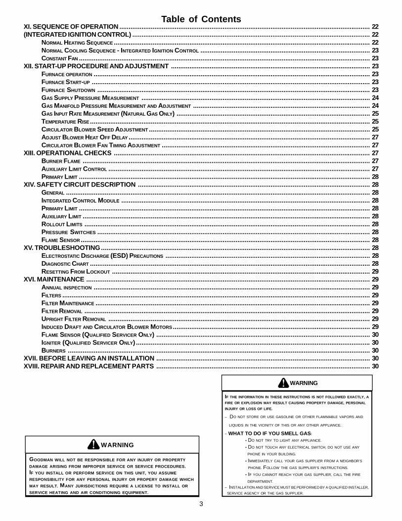
Table of ContentsXI. SEQUENCE OF OPERATION ........................................................................................................................................ 22(INTEGRATED IGNITION CONTROL) ................................................................................................................................. 22
NORMAL HEATING SEQUENCE ........................................................................................................................................... 22NORMAL COOLING SEQUENCE - INTEGRATED IGNITION CONTROL ............................................................................................ 23CONSTANT FAN .............................................................................................................................................................. 23
XII. START-UP PROCEDURE AND ADJUSTMENT ............................................................................................................ 23FURNACE OPERATION ...................................................................................................................................................... 23FURNACE START-UP ....................................................................................................................................................... 23FURNACE SHUTDOWN .................................................................................................................................................... 23GAS SUPPLY PRESSURE MEASUREMENT ............................................................................................................................ 24GAS MANIFOLD PRESSURE MEASUREMENT AND ADJUSTMENT ................................................................................................ 24GAS INPUT RATE MEASUREMENT (NATURAL GAS ONLY) ......................................................................................................... 25TEMPERATURE RISE........................................................................................................................................................ 25CIRCULATOR BLOWER SPEED ADJUSTMENT ........................................................................................................................ 25ADJUST BLOWER HEAT OFF DELAY ................................................................................................................................... 27CIRCULATOR BLOWER FAN TIMING ADJUSTMENT ................................................................................................................. 27
XIII. OPERATIONAL CHECKS ........................................................................................................................................... 27BURNER FLAME ............................................................................................................................................................ 27AUXILIARY LIMIT CONTROL .............................................................................................................................................. 27PRIMARY LIMIT .............................................................................................................................................................. 28
XIV. SAFETY CIRCUIT DESCRIPTION .............................................................................................................................. 28GENERAL ..................................................................................................................................................................... 28INTEGRATED CONTROL MODULE ....................................................................................................................................... 28PRIMARY LIMIT .............................................................................................................................................................. 28AUXILIARY LIMIT ............................................................................................................................................................ 28ROLLOUT LIMITS ........................................................................................................................................................... 28PRESSURE SWITCHES .................................................................................................................................................... 28FLAME SENSOR ............................................................................................................................................................. 28
XV. TROUBLESHOOTING.................................................................................................................................................. 28ELECTROSTATIC DISCHARGE (ESD) PRECAUTIONS ............................................................................................................... 28DIAGNOSTIC CHART ........................................................................................................................................................ 28RESETTING FROM LOCKOUT ............................................................................................................................................ 29
XVI. MAINTENANCE .......................................................................................................................................................... 29ANNUAL INSPECTION ...................................................................................................................................................... 29FILTERS ....................................................................................................................................................................... 29FILTER MAINTENANCE ..................................................................................................................................................... 29FILTER REMOVAL ........................................................................................................................................................... 29UPRIGHT FILTER REMOVAL .............................................................................................................................................. 29INDUCED DRAFT AND CIRCULATOR BLOWER MOTORS........................................................................................................... 29FLAME SENSOR (QUALIFIED SERVICER ONLY) .................................................................................................................... 30IGNITER (QUALIFIED SERVICER ONLY) ............................................................................................................................... 30BURNERS .................................................................................................................................................................... 30
XVII. BEFORE LEAVING AN INSTALLATION .................................................................................................................... 30XVIII. REPAIR AND REPLACEMENT PARTS .................................................................................................................... 30
WARNING
IF THE INFORMATION IN THESE INSTRUCTIONS IS NOT FOLLOWED EXACTLY, AFIRE OR EXPLOSION MAY RESULT CAUSING PROPERTY DAMAGE, PERSONALINJURY OR LOSS OF LIFE.
– DO NOT STORE OR USE GASOLINE OR OTHER FLAMMABLE VAPORS AND
LIQUIDS IN THE VICINITY OF THIS OR ANY OTHER APPLIANCE.
– WHAT TO DO IF YOU SMELL GAS:
• DO NOT TRY TO LIGHT ANY APPLIANCE.
• DO NOT TOUCH ANY ELECTRICAL SWITCH; DO NOT USE ANY
PHONE IN YOUR BUILDING.
• IMMEDIATELY CALL YOUR GAS SUPPLIER FROM A NEIGHBOR’S
PHONE. FOLLOW THE GAS SUPPLIER’S INSTRUCTIONS.
• IF YOU CANNOT REACH YOUR GAS SUPPLIER, CALL THE FIRE
DEPARTMENT.– INSTALLATION AND SERVICE MUST BE PERFORMED BY A QUALIFIED INSTALLER, SERVICE AGENCY OR THE GAS SUPPLIER.
WARNING
GOODMAN WILL NOT BE RESPONSIBLE FOR ANY INJURY OR PROPERTYDAMAGE ARISING FROM IMPROPER SERVICE OR SERVICE PROCEDURES.IF YOU INSTALL OR PERFORM SERVICE ON THIS UNIT, YOU ASSUME RESPONSIBILITY FOR ANY PERSONAL INJURY OR PROPERY DAMAGE WHICHMAY RESULT. MANY JURISDICTIONS REQUIRE A LICENSE TO INSTALL ORSERVICE HEATING AND AIR CONDITIONING EQUIPMENT.

4
PAGE 4I. WARNINGS
WARNING
SHOULD OVERHEATING OCCUR OR THE GAS SUPPLY FAIL TO SHUT OFF, TURN
OFF THE MANUAL GAS SHUTOFF VALVE EXTERNAL TO THE FURNACE BEFORE
TURNING OFF THE ELECTRICAL SUPPLY.
CARBON MONOXIDE POISONING HAZARD
-
Special Warning for Installation of Furnace or Air Handling Units inEnclosed Areas such as Garages, Utility Rooms or Parking Areas
Carbon monoxide producing devices (such as an automobile, spaceheater, gas water heater, etc.) should not be operated in enclosed areassuch as unventilated garages, utility rooms or parking areas because ofthe danger of carbon monoxide (CO) poisoning resulting from the exhaustemissions. If a furnace or air handler is installed in an enclosed area suchas a garage, utility room or parking area and a carbon monoxide producingdevice is operated therein, there must be adequate, direct outsideventilation.
This ventilation is necessary to avoid the danger of CO poisoning whichcan occur if a carbon monoxide producing device continues to operate inthe enclosed area. Carbon monoxide emissions can be (re)circulatedthroughout the structure if the furnace or air handler is operating in anymode.
CO can cause serious illness including permanent brain damage or death.
B10259-216
WARNING
TO PREVENT PERSONAL INJURY OR DEATH DUE TO IMPROPER INSTALLATION,ADJUSTMENT, ALTERATION, SERVICE OR MAINTENANCE, REFER TO THISMANUAL. FOR ADDITIONAL ASSISTANCE OR INFORMATION, CONSULT AQUALIFIED INSTALLER, SERVICE AGENCY OR THE GAS SUPPLIER.
TO THE OWNER
It is important that you fill out the owner’s registration card andmail it today. This will assist us in contacting you should any serviceor warranty information change in the future. When filling in theregistration card, be sure to include the model, manufacturing, andserial numbers, plus the installation date.
Your warranty certificate is also supplied with the unit. Read thewarranty carefully and note what is covered. Keep the warrantycertificate in a safe location for future reference.
If additional information or operating instructions are required,contact the dealer where the purchase was made.
Homeowner Notice:
If the residence is left unattended for an extended period of time(i.e., 4 hours or greater), have your heating system periodicallychecked to ensure proper operation. Potential circumstancesbeyond our control such as power outages, gas serviceinterruptions, product installation, or component failures couldresult in heating system operational problems.
TO THE INSTALLER
Before installing this unit, please read this manual thoroughly tofamiliarize yourself with specific items which must be adhered to,including but not limited to: unit maximum external static pressure,gas pressures, BTU input rating, proper electrical connections,circulating air temperature rise, minimum or maximum CFM, andmotor speed connections, and venting. These furnaces aredesigned for Category I venting only.
WARNING
TO PREVENT POSSIBLE PERSONAL INJURY OR DEATH DUE TO ASPHYXIATION, THIS FURNACE MUST BE CATEGORY I VENTED. DO NOT VENT USINGCATEGORY III VENTING. PROVISIONS MUST BE MADE FOR VENTING COMBUSTION PRODUCTSOUTDOORS THROUGH A PROPER VENTING SYSTEM. THE LENGTH OF FLUE PIPECOULD BE A LIMITING FCTOR IN LOCATING THE FURNACE.
TRANSPORTATION DAMAGE
All units are securely packed in shipping containers testedaccording to International Safe Transit Association specifications.The carton must be checked upon arrival for external damage. Ifdamage is found, a request for inspection by carrier’s agent mustbe made in writing immediately.
The furnace must be carefully inspected on arrival for damageand bolts or screws which may have come loose in transit. In theevent of damage the consignee should:
1. Make a notation on delivery receipt of any visible damageto shipment or container.
2. Notify carrier promptly and request an inspection.3. With concealed damage, carrier must be notified as soon
as possible - preferably within five days.4. File the claim with the following support documents within
a nine month statute of limitations.• Original or certified copy of the Bill of Lading, or indemnity
bond.• Original paid freight bill or indemnity in lieu thereof.• Original or certified copy of the invoice, showing trade and
other discounts or reductions.• Copy of the inspection report issued by carrier ’s
representative at the time damage is reported to carrier.The carrier is responsible for making prompt inspection of damageand for a thorough investigation of each claim. The distributor ormanufacturer will not accept claims from dealers for transportationdamage.
Keep this literature in a safe place for future reference.
II. SAFETYAdhere to the following warnings and cautions when installing,adjusting, altering, servicing, or operating the furnace.
TO PREVENT PERSONAL INJURY OR DEATH DUE TO IMPROPER INSTALLATION,ADJUSTMENT, ALTERATION, SERVICE OR MAINTENANCE, REFER TO THISMANUAL. FOR ADDITIONAL ASSISTANCE OR INFORMATION, CONSULT AQUALIFIED INSTALLER, SERVICE AGENCY OR THE GAS SUPPLIER.
WARNING

5
WARNING
THIS PRODUCT CONTAINS OR PRODUCES A CHEMICAL OR CHEMICALS WHICHMAY CAUSE SERIOUS ILLNESS OR DEATH AND WHICH ARE KNOWN TO THESTATE OF CALIFORNIA TO CAUSE CANCER, BIRTH DEFECTS OR OTHERREPRODUCTIVE HARM.
WARNING
TO PREVENT POSSIBLE PROPERTY DAMAGE, PERSONAL INJURY OR DEATHDUE TO ELECTRICAL SHOCK, THE FURNACE MUST BE LOCATED TO PROTECTTHE ELECTRICAL COMPONENTS FROM WATER.
WARNING
HEATING UNIT SHOULD NOT BE UTILIZED WITHOUT REASONABLE, ROUTINE,INSPECTION, MAINTENANCE AND SUPERVISION. IF THE BUILIDNG IN WHICH ANYSUCH DEVICE IS LOCATED WILL BE VACANT, CARE SHOULD BE TAKEN THATSUCH DEVICE IS ROUTINELY INSPECTED, MAINTAINED AND MONITORED. IN THEEVENT THAT THE BUILDING MAYBE EXPOSED TO FREEZING TEMPERATURESAND WILL BE VACANT, ALL WATER-BEARING PIPES SHOULD BE DRAINED, THEBUILDING SHOULD BE PROPERLY WINTERIZED, AND THE WATER SOURCECLOSED. IN THE EVENT THAT THE BUILDING MAY BE EXPOSED TO FREEZINGTEMPERATURES AND WILL BE VACANT, ANY HYDRONIC COIL UNITS SHOULDBE DRAINED AS WELL AND, IN SUCH CASE, ALTERNATIVE HEAT SOURCESSHOULD BE UTILIZED.
ADDITIONAL SAFETY CONSIDERATIONS• This furnace is approved for Category I Venting only.• Provisions must be made for venting combustion products
outdoors through a proper venting system. The length offlue pipe could be a limiting factor in locating the furnace.
ELECTROSTATIC DISCHARGE (ESD) PRECAUTIONS
NOTE: Discharge body’s static electricity before touching unit. Anelectrostatic discharge can adversely affect electrical components.
Use the following precautions during furnace installation andservicing to protect the integrated control module from damage.By putting the furnace, the control, and the person at the sameelectrostatic potential, these steps will help avoid exposing theintegrated control module to electrostatic discharge. This procedureis applicable to both installed and non-installed (ungrounded)furnaces.
1. Disconnect all power to the furnace. Do not touch theintegrated control module or any wire connected to thecontrol prior to discharging your body’s electrostatic chargeto ground.
2. Firmly touch a clean, unpainted, metal surface of thefurnaces near the control. Any tools held in a person’shand during grounding will be discharged.
3. Service integrated control module or connecting wiringfollowing the discharge process in step 2. Use caution notto recharge your body with static electricity; (i.e., do not moveor shuffle your feet, do not touch ungrounded objects, etc.).If you come in contact with an ungrounded object, repeatstep 2 before touching control or wires.
4. Discharge your body to ground before removing a newcontrol from its container. Follow steps 1 through 3 ifinstalling the control on a furnace. Return any old or newcontrols to their containers before touching any ungroundedobject.
III. PRODUCT APPLICATIONThis furnace is primarily designed for residential home-heatingapplications. It is NOT designed or certified for use in mobile homes,trailers or recreational vehicles. Neither is it designed or certifiedfor outdoor applications. The furnace must be installed indoors(i.e., attic space, crawl space, or garage area provided the garagearea is enclosed with an operating door).
This furnace can be used in the following non-industrial commercialapplications:
Schools, Office buildings, Churches, Retail stores,Nursing homes, Hotels/motels, Common or office areas
In such applications , the furnace must be installed with the followingstipulations:
• It must be installed per the installation instructions providedand per local and national codes.
• It must be installed indoors in a building constructed on site.• It must be part of a ducted system and not used in a free air
delivery application.• It must not be used as a “make-up” air unit.• All other warranty exclusions and restrictions apply.
This furnace may be used as a construction site heater ONLY ifthe following conditions are met:
• The vent system is permanently installed per theseinstallation instructions.
• A room thermostat is used to control the furnace. Fixedjumpers that provide continuous heating CANNOT be used.
• Return air ducts are provided and sealed to the furnace.• A return air temperature range between 60ºF (16ºC) and
80ºF (27ºC) is maintained.Air filters are installed in the system and maintained duringconstruction, replaced as appropriate during construction,and upon completion of construction are replaced.
• The input rate and temperature rise are set per the furnacerating plate.
• 100% outside air is provided for combustion air requirementsduring construction. Temporary ducting can be used.NOTE: Do not connect the temporary duct directly to thefurnace. The duct must be sized according to the instructionsunder Section V, Combustion and Ventilation AirRequirements, Section 5.3.3.
• The furnace heat exchanger, components, duct system, airfilters and evaporator coils are thoroughly cleaned followingfinal construction clean up.
• All furnace operating conditions (including ignition, input rate,temperature rise and veting) are verified according to theseinstallation instructions.
NOTE: The Commonwealth of Massachusetts requires that thefollowing additional requirements must also be met:
• Gas furnaces must be installed by a licensed plumber orgas fitter.
• A T-handle gas cock must be used.• If the unit is to be installed in an attic, the passageway to
and the service area around the unit must have flooring.To ensure proper installation and operation, thoroughly read thismanual for specifics pertaining to the installation and applicationof this product.

6
The GMV8 series of furnaces meet the California NOx emissionstandards and California seasonal efficiency standards. ANNUALinspections of the furnace and its vent system is stronglyrecommended.
IV. LOCATION REQUIREMENTS AND CONSIDERATIONSGENERAL
WARNING
POSSIBLE PROPERTY DAMAGE, PERSONAL INJURY OR DEATH DUE TO FIRE,EXPLOSION, SMOKE, SOOT, CONDENSTAION, ELECTRICAL SHOCK OR CARBONMONOXIDE MAY RESULT FROM IMPROPER INSTALLATION, REPAIR, OPERATION,OR MAINTENANCE OF THIS PRODUCT.
WARNING
TO PREVENT POSSIBLE EQUIPMENT DAMAGE, PROPERTY DAMAGE, PERSONALINJURY OR DEATH, THE FOLLOWING BULLET POINTS MUST BE OBSERVEDWHEN INSTALLING THE UNIT.
Follow the instructions listed below when selecting a furnacelocation. Refer also to the guidelines provided in Section V,Combustion and Ventilation Air Requirements.
• Centrally locate the furnace with respect to the proposed orexisting air distribution system.
• Ensure the temperature of the return air entering the furnaceis between 55°F and 100°F when the furnace is heating.
• Provisions must be made for venting combustion productsoutdoors through a proper venting system. The length offlue pipe could be a limiting factor in locating the furnace.
• Ensure adequate combustion air is available for the furnace.Improper or insufficient combustion air can expose buildingoccupants to gas combustion products that could includecarbon monoxide. Refer to Section V, Combustion andVentilation Air Requirements.
• The furnace must be level. If the furnace is to be set on afloor that may become wet or damp at times, the furnaceshould be supported above the floor on a concrete basesized approximately 1-1/2" larger than the base of thefurnace.
• Ensure upflow or horizontal furnaces are not installed directlyon carpeting, or any other combustible material. The onlycombustible material allowed is wood.
• Exposure to contaminated combustion air will result in safetyand performance-related problems. Do not install thefurnace where the combustion air is exposed to the followingsubstances:
chlorinated waxes or cleanerschlorine-based swimming pool chemicals
water softening chemicalsdeicing salts or chemicals
carbon tetrachloridehalogen type refrigerants
cleaning solutions (such as perchloroethylene)printing inks
paint removersvarnishes
hydrochloric acidcements and glues
antistatic fabric softeners for clothes dryersand masonry acid washing materials
WARNING
POSSIBLE PROPERTY DAMAGE, PERSONAL INJURY OR DEATH DUE TO FIRE,EXPLOSION, SMOKE, SOOT, CONDENSTAION, ELECTRICAL SHOCK OR CARBONMONOXIDE MAY RESULT FROM IMPROPER INSTALLATION, REPAIR, OPERATION,OR MAINTENANCE OF THIS PRODUCT.
WARNING
TO PREVENT PROPERTY DAMAGE, PERSONAL INJURY OR DEATH DUE TO FIRE,DO NOT INSTALL THIS FURNACE IN A MOBILE HOME, TRAILER, OR RECREATIONALVEHICLE.
To ensure proper furnace operation, install, operate and maintainthe furnace in accordance with these installation and operationinstructions, all local building codes and ordinances. In theirabsence, follow the latest edition of the National Fuel Gas Code(NFPA 54/ANSI Z223.1), and/or CAN/CSA B149 Installation Codes,local plumbing or waste water codes, and other applicable codes.
A copy of the National Fuel Gas Code (NFPA 54/ANSI Z223.1) canbe obtained from any of the following:
American National Standards Institute1430 Broadway
New York, NY 10018
National Fire Protection Association1 Batterymarch ParkQuincy, MA 02269
CSA International8501 East Pleasant Valley
Cleveland, OH 44131A copy of the CAN/CSA B149 Installation Codes can also beobtained from:
CSA International178 Rexdale Boulevard
Etobicoke, Ontario, Canada M9W 1R3The rated heating capacity of the furnace should be greater than orequal to the total heat loss of the area to be heated. The total heatloss should be calculated by an approved method or in accordancewith “ASHRAE Guide” or “Manual J-Load Calculations” publishedby the Air Conditioning Contractors of America.
In the USA, this furnace MUST be installed in accordance with thelatest edition of the ANSI Z223.1 booklet entitled “National FuelGas Code” (NFPA 54), and the requirements or codes of the localutility or other authority having jurisdiction. In Canada, this furnacemust be installed in accordance with the current CAN/CGA-B149.1& 2 Gas Installation Codes, local plumbing or waste water codesand other applicable codes.
Additional helpful publications available from the NFPA are, NFPA90A - Installation of Air Conditioning and Ventilating System andNFPA 90B - Warm Air Heating and Air Conditioning System.
All venting shall be in accordance with PART 7, Venting ofEquipment, of the National Fuel Gas Code, ANSI Z223.1, orapplicable local building and/or air conditioning codes. Thesepublications are available from:
National Fire Protection Association, Inc.Batterymarch ParkQuincy, MA 02269

7
• If the furnace is used in connection with a cooling unit, installthe furnace upstream or in parallel with the cooling unit coil.Premature heat exchanger failure will result if the coolingunit coil is placed ahead of the furnace.
• If the furnace is installed in a residential garage, positionthe furnace so that the burners and ignition source arelocated not less than 18 inches (457 mm) above the floor.Protect the furnace from physical damage by vehicles.
• If the furnace is installed horizontally, the furnace accessdoors must be vertical so that the burners fire horizontallyinto the heat exchanger. Do not install the unit with theaccess doors on the “up/top” or “down/bottom” side of thefurnace.
• Do not connect this furnace to a chimney flue that serves aseparate appliance designed to burn solid fuel.
CLEARANCES AND ACCESSIBILITY
Unobstructed front clearance of 24" for servicing is recommended.
TOPB1-VENT SINGLE (PLENUM)
1" 6" 1" 3" 0" 1"
VENT SIDES FRONT BACK
Top clearance for horizontal configuration - 1"
HORIZONTAL INSTALLATION
Line contact to framing is permitted when installed in the horizontalconfiguration. Line contact is defined as the portion of the cabinetthat is formed by the intersection of the top and side.ACCESSIBILITY CLEARANCE, WHERE GREATER, SHOULDTAKE PRECEDENCE OVER MINIMUM FIRE PROTECTIONCLEARANCE. A gas-fired furnace for installation in a residentialgarage must be installed so that the ignition source and burnersare located not less than eighteen inches (18") above the floor andis protected or located to prevent physical damage by vehicles. Agas furnace must not be installed directly on carpeting, tile, orother combustible materials other than wood flooring.
Vent Pipe Clearance to Combustibles -6" using Single Wall Connector or 1" using B-1 vent.
Top - 1"
SideClearance - 1"
Back - 0"
Front Clearance - 3"
• Adequate combustion/ combustion air must be supplied tothe closet.
• Furnace must be completely sealed to floor or base.Combustion/ ventilation air supply pipes must terminate 12"from top of closet and 12" from floor of closet. DO NOTremove solid base plate for bottom return.
• Return air ducts must be completely sealed to the furnaceand terminate outside the enclosure surfaces.
FURNACE SUSPENSION
If suspending the furnace from rafters or joist, use 3/8" threadedrod and 2”x2”x3/8” angle iron as shown below. The length of rodwill depend on the application and the clearances necessary.
TILT OUTWARD TO ALLOW FORDOOR AND CIRCULATOR BLOWER
REMOVAL
3/8" DIAMETER THREADED ROD
(6 PLACES)
PROVIDE 8" MINMUM CLEARANCE BETWEENCENTER ROD AND FURNACE CABINET
TO ALLOW FOR CIRCULATOR BLOWER REMOVAL
ASSURE FURNACE IS LEVEL FROM
END TO END AND HAS A SLIGHTFORWARD TILT WITH THE FRONT
OF THE FURNACE 0"-3/4" BELOW THE BACK OF THE FURNACE
POSITION AS CLOSE AS POSSIBLETO BLOWER DECK TO ALLOW FOR
CIRCULATOR BLOWER REMVOAL
HOLD DOWN NUTS
SUPPORTNUTS
2"x2"x3/8"ANGLE IRON(3 PLACES)
Suspended Furnace
EXISTING FURNACE REMOVAL
NOTE: When an existing furnace is removed from a venting systemserving other appliances, the venting system may be too large toproperly vent the remaining attached appliances.
The following vent testing procedure is reproduced from theAmerican National Standard/National Standard of Canada forGas-Fired Central Furnaces ANSI Z21.47b-2002, CSA-2.3b-2002Section 1.23.1. The following steps shall be followed with eachappliance connected to the venting system placed in operation,while any other appliances connected to the venting system arenot in operation:
a. Seal any unused openings in the venting system;b. Inspect the venting system for proper size and horizontal
pitch, as required by the National Fuel Gas Code, ANSIZ223.1 or the CAN/CSA B149 Installation Codes and theseinstructions. Determine that there is no blockage orrestriction, leakage, corrosion and other deficiencies whichcould cause an unsafe condition;
c. In so far as practical, close all building doors and windowsand all doors between the space in which the appliance(s)connected to the venting system are located and otherspaces of the building. Turn on clothes dryers and anyappliance not connected to the venting system. Turn on anyexhaust fans, such as range hoods and bathroom exhausts,so they shall operate at maximum speed. Do not operate asummer exhaust fan. Close fireplace dampers;
d. Follow the lighting instructions. Place the appliance beinginspected in operation. Adjust thermostat so appliance shalloperate continuously;
e. Test for draft hood equipped appliance spillage at the drafthood relief opening after 5 minutes of main burner operation.Use the flame of a match or candle;
f. After it has been determined that each appliance connectedto the venting system properly vents when tested as outlinedabove, return doors, windows, exhaust fans, fireplacedampers and any other gas burning appliance to theirprevious conditions of use;
g. If improper venting is observed during any of the above tests,the venting system must be corrected.
Corrections must be in accordance with the latest edition of theNational Fuel Gas Code NFPA 54/ANSI Z223.1 and/or CAN/CSAB149 Installation Codes.

8
Most homes will require outside air be supplied to the furnacearea by means of ventilation grilles or ducts connecting directly tothe outdoors or spaces open to the outdoors such as attics orcrawl spaces.
The following information on air for combustion and ventilation isreproduced from the National Fuel Gas Code NFPA 54/ANSIZ223.1 Section 5.3.
5.3.1 General:
(a) The provisions of 5.3 apply to gas utilization equipmentinstalled in buildings and which require air for combustion,ventilation and dilution of flue gases from within the building.They do not apply to (1) direct vent equipment which isconstructed and installed so that all air for combustion isobtained from the outside atmosphere and all flue gasesare discharged to the outside atmosphere, or (2) enclosedfurnaces which incorporate an integral total enclosure anduse only outside air for combustion and dilution of flue gases.
(b) Equipment shall be installed in a location in which thefacilities for ventilation permit satisfactory combustion of gas,proper venting and the maintenance of ambient temperatureat safe limits under normal conditions of use. Equipmentshall be located so as not to interfere with proper circulationof air. When normal infiltration does not provide thenecessary air, outside air shall be introduced.
(c) In addition to air needed for combustion, process air shallbe provided as required for: cooling of equipment or material,controlling dew point, heating, drying, oxidation or dilution,safety exhaust, odor control, and air for compressors.
(d) In addition to air needed for combustion, air shall be suppliedfor ventilation, including all air required for comfort andproper working conditions for personnel.
(e) While all forms of building construction cannot be coveredin detail, air for combustion, ventilation and dilution of fluegases for gas utilization equipment vented by natural draftnormally may be obtained by application of one of themethods covered in 5.3.3 and 5.3.4.
(f) Air requirements for the operation of exhaust fans, kitchenventilation systems, clothes dryers, and fireplaces shall beconsidered in determining the adequacy of a space toprovide combustion air requirements.
5.3.2 Equipment Located in Unconfined Spaces:In unconfined spaces (see definition below) in buildings,infiltration may be adequate to provide air for combustionventilation and dilution of flue gases. However, in buildingsof tight construction (for example, weather stripping, heavilyinsulated, caulked, vapor barrier, etc.), additional air mayneed to be provided using the methods described in 5.3.3-b or 5.3.4.
Space, Unconfined.For purposes of this Code, a space whose volume is notless than 50 cubic feet per 1,000 BTU per hour of theaggregate input rating of all appliances installed in thatspace. Rooms communicating directly with the space inwhich the appliances are installed through openings notfurnished with doors, are considered a part of the unconfinedspace.
5.3.3 Equipment Located in Confined Spaces:
(a) All Air from Inside the Building: The confined space shall beprovided with two permanent openings communicating
If resizing is required on any portion of the venting system, use theappropriate table in Appendix G in the latest edition of the NationalFuel Gas Code ANSI Z223.1 and/or CAN/CSA B149 InstallationCodes.
THERMOSTAT LOCATION
In an area having good air circulation, locate the thermostat aboutfive feet high on a vibration-free inside wall. Do not install thethermostat where it may be influenced by any of the following:
• Drafts, or dead spots behind doors, in corners, or undercabinets.
• Hot or cold air from registers.• Radiant heat from the sun.• Light fixtures or other appliances.• Radiant heat from a fireplace.• Concealed hot or cold water pipes, or chimneys.• Unconditioned areas behind the thermostat, such as an
outside wall.
HOTCOLD
DRAFTS OR DEAD SPOTS-BEHIND DOORS -IN CORNERS -UNDER CABINETS
Thermostat InfluencesConsult the instructions packaged with the thermostat for mountinginstructions and further precautions.
V. COMBUSTION AND VENTILATION AIR REQUIREMENTS
WARNING
TO AV OID PRO PERTY DAM AGE , P ERS ONAL INJURY OR DE ATH, S UFFIC IENTFRES H A IR FO R P ROPE R COM BUS TION AND VE NTILATION OF FLUE G AS ES M USTBE SUPP LIE D. M O ST HOM ES REQ UIRE OUTSIDE A IR BE SUP PLIE D INTO THEFURNACE ARE A.
Improved construction and additional insulation in buildings havereduced heat loss by reducing air infiltration and escape arounddoors and windows. These changes have helped in reducingheating/cooling costs but have created a problem supplyingcombustion and ventilation air for gas fired and other fuel burningappliances. Appliances that pull air out of the house (clothes dryers,exhaust fans, fireplaces, etc.) increase the problem by starvingappliances for air.
House depressurization can cause back drafting or impropercombustion of gas-fired appliances, thereby exposing buildingoccupants to gas combustion products that could include carbonmonoxide.
If this furnace is to be installed in the same space with other gasappliances, such as a water heater, ensure there is an adequatesupply of combustion and ventilation air for the other appliances.Refer to the latest edition of the National Fuel Gas Code NFPA 54/ANSI Z223.1 (Section 5.3), or CAN/CSA B149 Installation Codes(Sections 7.2, 7.3, or 7.4), or applicable provisions of the localbuilding codes for determining the combustion air requirements forthe appliances.
This furnace must use indoor air for combustion. It cannot beinstalled as a direct vent (i.e., sealed combustion) furnace.

9
directly with an additional room(s) of sufficient volume sothat the combined volume of all spaces meets the criteriafor an unconfined space. The total input of all gas utilizationequipment installed in the combined space shall beconsidered in making this determination. Each opening shallhave a minimum free area of 1 square inch per 1,000 BTUper hour of the total input rating of all gas utilizationequipment in the confined space, but not less than 100square inches. One opening shall be within 12 inches of thetop and one within 12 inches of the bottom of the enclosure.
FurnaceWaterHeater
Opening
Chimney or Gas Vent
Opening
NOTE: Each opening must havea free area of not less than one square inch per 1000 BTU of the total input rating of all equip-ment in the enclosure, but notless than 100 square inches.
Equipment Located in Confined Spaces;All Air from Inside Building. See 5.3.3-a.
(b) All Air from Outdoors: The confined space shall be providedwith two permanent openings, one commencing within 12inches of the top and one commencing within 12 inches ofthe bottom of the enclosure. The openings shallcommunicate directly, or by ducts, with the outdoors orspaces (crawl or attic) that freely communicate with theoutdoors.
1. When directly communicating with the outdoors, eachopening shall have a minimum free area of 1 square inchper 4,000 BTU per hour of total input rating of allequipment in the enclosure.
Furnace
WaterHeater
Outlet Air
Chimney or Gas Vent
NOTE: The inlet and outlet airopenings must each have a freearea of not less than one squareinch per 4000 BTU of thetotal input rating of all equipmentin the enclosure.
Inlet Air
Ventilation louvers forunheated crawl space
Alternateair inlet
Ventilation louvers(each end of attic)
Equipment Located in Confined Spaces; All Air from Outdoors—InletAir from Ventilated Crawl Space and Outlet Air to Ventilated Attic.
See 5.3.3-b
2. When communicating with the outdoors through verticalducts, each opening shall have a minimum free area of1 square inch per 4,000 BTU per hour of total input ratingof all equipment in the enclosure.
Furnace
WaterHeater
Outlet Air
Chimney or Gas Vent
NOTE: The inlet and outlet airopenings must each have a freearea of not less than one squareinch per 4000 BTU of thetotal input rating of all equipmentin the enclosure.
Inlet a ir duct[ends 1 ft (300 mm)above floor]
Ventilation louvers(each end of attic)
Equipment Located in Confined Spaces; All Air from OutdoorsThrough Ventilated Attic. See 5.3.3-b.
3. When communicating with the outdoors through horizontalducts, each opening shall have a minimum free area of1 square inch per 2,000 BTU per hour of total input ratingof all equipment in the enclosure.
FurnaceWaterHeater
Chimney or Gas Vent
NOTE: The air duct openingsmust have a free area of notless than one square inch per2000 BTU of the total inputrating of all equipment in theenclosure*.Outlet air duct
Inlet air duct
Equipment Located in Confined Spaces;
All Air from Outdoors. See 5.3.3-b.*If the appliance room is located against an outside wall and theair openings communicate directly with the outdoors, each openingshall have a free area of not less than one square inch per 4,000BTU per hour of the total input rating of all appliances in theenclosure.
4. When ducts are used, they shall be of the same cross-sectional area as the free area of the openings to whichthey connect. The minimum dimension of rectangular airducts shall not be less than 3 inches.

10
Furnace
WaterHeater
Opening
Chimney or Gas VentNOTE: The single opening must havea free area of not less than one square inch per 3000 BTU of the total input rating of all equip-ment in the enclosure, but not less than the sum of the areas of all ventconnectors in the confined space.
AlternateOpeningLocation
Equipment Located in Confined Spaces; All Air from Outdoors -Single Air Opening. See 5.3.3-b.
5. One permanent opening may be permitted, provided theequipment has clearances of at least 1” from the sidesand back and 6” from the front. The opening shallcommunicate directly with the outdoors and must belocated within 12” of the top of the enclosure. Theminimum free area of the opening shall be 1 square inchper 3,000 BTU per hour of total input rating of allequipment in the enclosure. The minimum free area shallnot be less than the sum of the areas of all ventconnectors in the confined space.
5.3.4 Specially Engineered Installations:
The requirements of 5.3.3 shall not necessarily govern whenspecial engineering, approved by the authority havingjurisdiction, provides an adequate supply of air for combustion,ventilation, and dilution of flue gases.
5.3.5 Louvers and Grilles:
In calculating free area in 5.3.3, consideration shall be givento the blocking effect of louvers, grilles or screens protectingopenings. Screens used shall not be smaller than 1/4 inchmesh. If the area through a design of louver or grille is known,it should be used in calculating the size of opening required toprovide the free area specified. If the design and free area isnot known, it may be assumed that wood louvers will have 20-25 percent free area and metal louvers and grilles will have60-75 percent free area. Louvers and grilles shall be fixed inthe open position or interlocked with the equipment so thatthey are opened automatically during equipment operation.
5.3.6 Special Conditions Created by Mechanical Exhaustingor Fireplaces:
Operation of exhaust fans, ventilation systems, clothes dryers,or fireplaces may create conditions requiring special attentionto avoid unsatisfactory operation of installed gas utilizationequipment.
VI. CATEGORY I VENTING (VERTICAL VENTING)
WARNING
TO PREVENT POSSIBLE PERSONAL INJURY OR DEATH DUE TO ASPHYXIATION, THIS FURNACE MUST BE CATEGORY I VENTED. DO NOT VENT USINGCATEGORY III VENTING.
Category I Venting is venting at a non-positive pressure. A furnacevented as Category I is considered a fan-assisted appliance and
the vent system does not have to be “gas tight.” NOTE: Gasfurnaces with induced draft blowers draw products of combustionthrough a heat exchanger allowing, in some instances, commonventing with natural draft appliances (i.e. water heaters).
All installations must be vented in accordance with National FuelGas Code NFPA 54/ANSI Z223.1 - latest edition. In Canada, thefurnaces must be vented in accordance with the National Standardof Canada, CAN/CSA B149.1 and CAN/CSA B149.2 - latest editionsand amendments.
NOTE: The vertical height of the Category I venting system mustbe at least as great as the horizontal length of the venting system.
WARNING
TO PREVENT POSSIBLE PERSONAL INJURY OR DEATH DUE TO ASPHYXIATION,COMMON VENTING WITH OTHER MANUFACTURER'S INDUCED DRAFT APPLIANCSIS NOT ALLOWED.
The minimum vent diameter for the Category I venting system isas shown below:
M INIM UM VENTUPFLOW
70 4 Inch90 4 Inch
115 5 Inch140 5 Inch
M ODEL
Under some conditions, larger vents than those shown above maybe required or allowed.
When an existing furnace is removed from a venting system servingother appliances, the venting system may be too large to properlyvent the remaining attached appliances.
Upflow or Horizontal units are shipped with the induced draftblower discharging from the top of the furnace. (“Top” is as viewedfor an upflow installation.) The induced draft blower can be rotated90 degrees for Category I venting (Figure 3). For horizontalinstallations, a four inch single wall pipe can be used to extend theinduced draft blower outlet 1/2” beyond the furnace cabinet. Ventthe furnace in accordance with the National Fuel Gas Code NFPA54/ANSI Z223.1 - latest edition. In Canada, vent the furnace inaccordance with the National Standard of Canada, CAN/CSAB149.1 and CAN/CSA B149.2 - latest editions and amendments.
Venting
THIS FURNACE IS NOT DESIGN CERTIFIED TO BEHORIZONTALLY VENTED.
Supply A ir
Upflow Rotated Induced Draft Blower

11
To rotate the induced draft blower counterclockwise, proceed asfollows:
1. Disconnect electrical power from the furnace.2. Disconnect the induced draft blower power leads, flue pipe,
and pressure switch tubing.3. Remove the round cutout from the appropriate side of the
furnace.4. Remove and save the four screws that hold the induced
draft blower to the flue collector box.5. Turn the induced draft blower 90 degrees clockwise, or
counterclockwise. The gasket is adhered to the back plateand will rotate with the blower assembly.
6. Reinstall the induced draft blower on the flue collector box,using the four screws removed in Step 3. Tighten screwsto provide an airtight seal.
7. Reconnect the induced draft blower power leads. NOTE:If the wires are not long enough, pull extra wire from thewire bundle in the blower compartment.
8. Remove and save the screw that holds the pressure switchto the furnace top panel.
9. Relocate the pressure switch to the same side as the flueoutlet in the hole provided.
10. Reconnect the draft blower power leads, flue pipe, andpressure switch tubing. Make sure that all wires and thepressure switch tubing are at least one inch from the fluepipe, or any other hot surfaces.
11. Restore power to the furnace.
WARNING
NEVER ALLOW THE PRODUCTS OF COMBUSTION, INCLUDING CARBONMONOXIDE, TO ENTER THE RETURN DUCTWORK OR CIRCULATION AIR SUPPLY.
VII. EXTERIOR MASONRY CHIMNEYS -CATEGORY I FURNACES ONLY
An exterior masonry chimney is defined as a “Masonry chimneyexposed to the outdoors on one or more sides below the roofline.” The ability to use a clay lined masonry chimney dependson a parameter not associated with interior chimneys. This variableis the geographic location of the installation. Researchers havediscovered that the winter design temperatures have a directimpact on the suitability of this type of venting. In most situations,the existing masonry chimneys will require a properly sized metallicliner.
WARNING
POSSIBILITY OF PROPER TY DAM AGE, P ERSO NAL INJUR Y OR DEATHDAM AGING CONDE NSATION CAN OCCUR IN SID E M ASO NRY CHIM NEYS W HEN A S INGLE FA N AS SIS TED CATEGO RY I APPLIANCE (80% AFUE FU RNACE) ISVENTED WITHOUT ADEQUATE D ILU TION AIR. DO NO T CONNEC T AN 80% FU RNACE TO A MAS ONRY CHIM NEY UNLES S TH E FURNACE IS COM M ON VENTEDW ITH A DRAFT HOOD EQ UIPPED APPLIANCE O R TH E CH IM NEY IS LINED W ITH AM ETAL LIN ER OR TYPE B M E TAL VENT. ALL INS TALLATIONS USING M ASO NRYCHIM NEY S MUS T B E S IZED IN ACCORDAN CE WITH THE APPR OPRIATE VENTINGTA BLES. IF AN 80% FURNAC E IS COM M ON VENTE D W ITH A DRAFT HOODEQUIPPED A PPLIANCE, THE POTEN TIAL FO R C ONDENSA TIO N DAM AG E MA YSTILL EXIS T W ITH EXTR EM ELY COLD COND ITIO NS, LONG VENT CONN ECTO RS,EXTERIOR C HIM N EYS, O R ANY CO M BINATION OF THESE CON DITION S. TH ERISK OF CONDENS ATION DAM AG E IS BEST AVO IDED BY USING THE M ASONR YCHIM NEY AS A PATHWAY FOR PRO PERLY SIZED M ETAL LINER O R TYPE BM ETAL VENT.
WashCrown
Clay Tile Size: 8" x 8" x12"(Each x 24" Length)
Clay Tile Size Generally12" x 12" (24" Length)
1/2" to 1" Air Space
Second Floor
First Floor
Attic Floor
Roof Line
ThroatDamper
Breech
Clean OutFan AssistedForced AirFurnace
Natural DraftWater Heater
Water HeaterVent Connector
Basement Floor
F.A.F. VentConnector
Figure 8 - Typical Multiple Flue Clay Tile Chimney
CHECKLIST SUMMARY
This checklist serves as a summary of the items to be checkedbefore venting an 80+ furnace into a masonry chimney. In addition,we recommend that a qualified serviceman use this checklist toperform a yearly inspection of the furnace venting system.
This checklist is only a summary. For detailed information on eachof the procedures mentioned, see the paragraph referenced witheach item.
This inspection is based upon a draft topical report, “MasonryChimney Inspection and Relining”, issued by the Gas ResearchInstitute. While not yet finalized, we believe this report representsthe best information on this subject which is currently available.

12
Termination 10 Feet Or Less From Ridge, Wall or Parapet
Termination More Than 10 Feet From Ridge, Wall or Parapet
CHECK 2 - ANY SOLID OR LIQUID FUEL APPLIANCES VENTED INTOTHIS CHIMNEY CHANNEL
Solid fuel appliances include fireplaces, wood stoves, coalfurnaces, and incinerators.
Proper ChimneyTermination?
(Check 1)
Line, terminate withlisted vent cap
(Fix 1)
No
Yes
Chimney channelfree of solid and
liquid fuelappliances?(Check 2)
Change ventingarrangements
(Fix 2)
No
Yes
Crown in goodcondition(Check 3)
Rebuild crown(Fix 3)
and/or Reline(Fix 4)
Yes
No
Yes
No
No
Reline(Fix 4)
Reline(Fix 4)
Cleanout free ofdebris?
(Check 4)
Liner in goodcondition?(Check 5)
Yes
Yes
No Reline(Fix 4)
Dilution airavailable?(Check 6)
Complete theinstallation.(Check 7)
CHECK 1 - PROPER CHIMNEY TERMINATION.A masonry chimney used as a vent for gas fired equipment mustextend at least three feet above the highest point where it passesthrough the roof. It must extend at least two feet higher than anyportion of a building within a horizontal distance of 10 feet. Inaddition, the chimney must terminate at least 3 feet above anyforced air inlet located within 10 feet. The chimney must extend atleast five feet above the highest connected equipment draft hoodoutlet or flue collar.
If the chimney does not meet these termination requirements, butall other requirements in the checklist can be met, it may be possiblefor a mason to extend the chimney. If this will not be practical, seeFix 1.
Chimney
3’ Min.
10’ or Less
2’ Min.2’ Min.
10’ or Less
3’ Min.
Chimney
Ridge2’ Min.
3’ Min.
More Than 10’
Chimney
NOTE: No height aboveparapet required whendistance from walls orparapet is more than 10 feet
Chimney
3’ Min.
Ridge
2’ Min.
10’
More than 10’
Wall orParapet
Wall orParapet
Height above anyroof surface within10 feet horizontally.
13
Liquid fuel appliances include oil furnaces, oil-fired boilers andoil-fired water heaters.
Appliances which burn propane (sometimes referred to as LP(liquefied petroleum)) gas are considered gas-fired appliances.
CHECK 3 - CHIMNEY CROWN CONDITION.Damage from condensate usually shows up first in the crown. Ifany of the following trouble signs are present, the condition of thecrown is not satisfactory:
a) Crown leaningb) Bricks missingc) Mortar missingd) Tile liner crackede) No tile linerf) Salt staining at mortar joints. (White stains, and mortar
becomes sandy and/or erodes.)For problems a, b, or c, see Fix 3. If problems d, e, or f are present,see Fix 4. IMPORTANT: It may be necessary to follow both Fix 3and Fix 4.
CHECK 4 - DEBRIS IN CLEANOUT
A cleanout (dropleg) must be present such that the upper edge ofthe cleanout cover is at least 12 inches below the lower edge ofthe lowest chimney inlet opening.
A chimney without a cleanout could become partially blocked bydebris. If no cleanout is present, the chimney must be refined (Fix4). Remove the cleanout cover, and examine the cleanout fordebris. If significant amounts of any of the following are found:
• Fuel oil residue• Bricks• Mortar or sand• Pieces of the tile liner• Rusted pieces of the metallic liner - reline the chimney (Fix
4).
CHECK 5 - LINER CONDITION.If a metal liner is present, it must be checked. It cannot be assumedthat all existing metal liners are correctly installed and in goodcondition.
Remove the lowest existing vent connector, and examine the insideof the elbow or tee at the base of the liner. A small amount of sootmay be considered acceptable, provided the installer vacuums itaway. If rusted pieces of the liner have collected here, the metalliner must be removed and replaced (Fix 4).
Next, gently tap the inside of the liner with a Phillips screwdriver.If the screwdriver perforates the liner, or if the tapping does notsound like metal hitting metal, the liner must be removed andreplaced (Fix 4).
Remember that all appliances must be vented inside the liner.Venting one appliance inside the liner and another applianceoutside the liner is not acceptable.
Next, use a flashlight and small mirror to sight up the liner. B ventmust be supported so as to not come into direct contact with thechimney walls or tile liner. If it is not, it can probably be rehung soas to be acceptable. A thimble or fire stop may be helpful here.
Flexible liners should be hung straight or nearly straight. If it isspiraled in the chimney and in good condition, it should be rehung.To do this, break the top seal; pull up and cut off the excess linerlength, and refit the top seal. Use caution when doing this, as thecut edges of flexible liners may be sharp.
The surfaces of the liner must be physically sound. If gaps orholes are present, the metal liner must be removed and replaced(Fix 4). Finally, confirm that the metal liner is the correct size forthe appliances to be installed. Use the GAMA tables and rules.
If a metal liner is not present, a clay tile liner must be present, orthe chimney must be lined (Fix 4).
Use a flashlight and small mirror at the cleanout or vent connectorto inspect the clay tile liner. If any of the following problems arepresent:
• Tile sections misaligned• Tile sections missing• Gaps between tile sections• Signs of condensate drainage at the cleanout or vent
connectors• Mortar protruding from between tile sections• Use of sewer pipe or drainage pipe rather than an approved
fire clay tile reline the chimney (Fix 4).Next, measure the size of the liner. It may be possible to do thisfrom the cleanout. The liner must be at least as large as theminimum size established by the tables in National Fuel Gas CodeNFPA 54/ANSI Z223.1 - latest edition and in the National Standardof Canada, CAN/CSA B149.1 and CAN/CSA B149.2 - latesteditions and amendments. If the liner is too small or too large,then the chimney must be relined (Fix 4).
CHECK 6 - DILUTION AIR.If gas-fired appliances are to be vented into a clay tile liner, asource of dilution air is required.
Dilution air cannot be obtained through:
• Induced draft appliances• Natural draft appliances with vent dampers
Sufficient dilution air can ordinarily be obtained through the drafthood of a natural draft appliance only if the appliance’s ventconnector does not include a vent damper. If dilution air will notbe available, the chimney must be relined (Fix 4).
CHECK 7 - COMPLETE THE INSTALLATION.If Checks 1 through 6 have been satisfactory, and the liner is anacceptable size as determined by the tables in National Fuel GasCode NFPA 54/ANSI Z223.1 - latest edition and in the NationalStandard of Canada, CAN/CSA B149.1 and CAN/CSA B149.2 -latest editions and amendments, then the clay tile liner canprobably be used as a vent for the gas appliances. However, theinstaller must keep in mind the following factors which may renderthe tile liner unsuitable for use as a vent:
• Extremely cold weather• Long vent connectors• Masonry chimneys with no air gap between the liner and
the bricks. (In practice, this can be difficult to detect.)• Exterior chimneys (The tables in National Fuel Gas Code
NFPA 54/ANSI Z223.1 - latest edition and in the NationalStandard of Canada, CAN/CSA B149.1 and CAN/CSAB149.2 - latest editions and amendments assume interiorchimneys.)
If, in the judgment of the local gas utility, installer, and/or localcodes; one or more of the above factors is likely to present aproblem, the chimney must be relined (Fix 4).

14
If a flexible liner is to be used, it must be made of the propermaterials:
• For most residential applications, an aluminum liner shouldbe acceptable.
• If the combustion air supplied to the furnace will becontaminated with compounds containing chlorine orfluorine, a liner of AL294C stainless steel should be used.Common sources of chlorine and fluorine compoundsinclude indoor swimming pools and chlorine bleaches, paintstrippers, adhesives, paints, varnishes, sealers, waxes(which are not yet dried) and solvents used duringconstruction and remodeling. Various commercial andindustrial processes may also be sources of chlorine/fluorine compounds.
• Heavier gauge 300 and 400 series stainless steel linerswere developed for use with oil or solid fuel appliances.They are not suitable for use with gas-fired appliances.Flexible liners specifically intended and tested for gasapplications are listed in the UL “Gas and Oil EquipmentDirectory”. (UL Standard 1777).
For sizing of flexible liners, see Note 22 and the tables in theNational Fuel Gas Code NFPA 54/ANSI Z223.1 - latest editionand in the National Standard of Canada, CAN/CSA B149.1 andCAN/CSA B149.2 - latest editions and amendments.
To install the liner, read and follow the liner manufacturer’sinstructions and your local codes. Excess liner length should bepulled out of the chimney and cut off. Use caution when doingthis, as the cut edges of flexible liners may be sharp. Do not spiralexcess liner inside of the chimney. Support the liner asrecommended by the liner manufacturer.
Some manufacturers of flexible liners offer an insulation sleevedesigned to be added to the liner before it is installed in thechimney. (Poured insulation, either vermiculite or other materials,is no longer recommended.) Insulation will need to be added tothe flexible liner if:
• It is required by the liner manufacturer’s instructions.• The previous liner was properly sized and installed, and
suffered from condensation damage.• It is required by your local building codes.
Even if none of those three conditions exist which require additionalliner insulation, the installer may wish to consider it if:
• The local climate is very cold.• The chimney is very tall.• The vent connectors used are very long or have a large
number of elbows.• Local experience indicates that flexible liners installed
without insulation are likely to have condensation problems.Insulation must be selected and installed in accordance with theliner manufacturer’s instructions.
Finally, cap the chimney and terminate the liner in accordancewith the liner manufacturer’s instructions.
VIII. ELECTRICAL CONNECTIONS
WARNING
TO AVOID THE RISK OF ELECTRICAL SHOCK, WIRING TO THE UNIT MUST BEPOLARIZED AND GROUNDED.
FIX 1 - LINER TERMINATION
Any cap or roof assembly used with a liner must be approved bythe liner manufacturer for such use. The liner and cap/roofassembly must then terminate above the roof in accordance withthe manufacturer’s instructions.
In some cases, a shorter extension above the roof may be possiblewith a liner than would be required with a masonry chimney.
For further information on relining, see Fix 4.
FIX 2 -CHANGE VENTING ARRANGEMENTS
If the masonry chimney has more than one channel, it may bepossible to vent the gas appliances into one channel and vent thesolid or liquid fuel appliance(s) into another channel(s). Do notvent an 80+ Furnace inside of a metal liner with other appliancesvented outside the liner.
Alternatively, the homeowner may agree to discontinue use of thefireplace (solid fuel appliance). If so, the tile liner must be cleanedto remove creosote buildup. The fireplace opening must then bepermanently sealed.
If oil-fired appliance(s) are being replaced by gas-firedappliance(s), the tile liner must first be cleaned to remove the fueloil residue.
If none of the above options is practical, the furnace may need tobe vented vertically with a B Vent.
Under some conditions, Furnace *9 could be installed rather thanan *8. The * 9 can be vented horizontally or vertically throughPVC pipe.
FIX 3 - REBUILD THE CROWN
If the chimney crown is damaged, a qualified mason must repair itin accordance with nationally recognized building codes orstandards. One such standard which may be referenced is theStandard for Chimneys, Fireplaces, Vents, and Solid Fuel BurningAppliances, ANSI/NFPA 211.
FIX 4 - RELINING
Relining options include B vent and flexible liners.
If the chimney has diagonal offsets, B vent probably cannot beused.
If B vent is to be used, it must be supported adequately. Supports(such as fire stops or thimbles) must be used to prevent the Bvent from coming into direct contact with the tile liner or chimneywalls. Direct contact would result in higher heat loss, with anincreased possibility of poor venting system performance.
It is not acceptable to vent one appliance inside the B vent andother appliances outside. The excess space between the B ventand the chimney walls must be covered at the top of the chimneyby a weatherproof, corrosion resistant flashing.
The B vent should then be topped with a listed vent cap. Thelisted vent cap will, when installed per the manufacturer’sinstructions, prevent problems due to rain, birds, or wind effects.
A B-vent installed as described in this section is considered to bean enclosed vent system, and the sizing tables in National FuelGas Code NFPA 54/ANSI Z223.1 - latest edition and in the NationalStandard of Canada, CAN/CSA B149.1 and CAN/CSA B149.2 -latest editions and amendments may be used.

15
WARNING
TO AVOID INJURY, ELECTRICAL SHOCK OR DEATH, DISCONNECT ELECTRICALPOWER BEFORE SERVICING OR CHANGING ANY ELECTRICAL WIRING.
CAUTION
LABEL ALL WIRES PRIOR TO DISCONNECTION WHEN SERVICING CONTROLS.WIRING ERRORS CAN CAUSE IMPROPER AND DANGEROUS OPERATION. VERIFY PROPER OPERATION AFTER SERVICING.
WARNING
TO AVOID THE RISK OF INJURY, ELECTRICAL SHOCK OR DEATH, THE FURNACEMUST BE ELECTRICALLY GROUNDED IN ACCORDANCE WITH LOCAL CODES OR,IN THEIR ABSENCE, WITH THE LATEST EDITION OF THE NATIONAL ELECTRICCODE.
WIRING HARNESS
The wiring harness is an integral part of this furnace. Field alterationto comply with electrical codes should not be required. Wires arecolor coded for identification purposes. Refer to the wiring diagramfor wire routings. If any of the original wire as supplied with thefurnace must be replaced, it must be replaced with wiring materialhaving a temperature rating of at least 105° C. Any replacementwiring must be a copper conductor.
WARNING
TO AVOID THE RISK OF ELECTRICAL SHOCK, WIRING TO THE UNIT MUST BEPOLARIZED AND GROUNDED.
115 VOLT LINE CONNECTIONS
Before proceeding with electrical connections, ensure that thesupply voltage, frequency, and phase correspond to that specifiedon the unit rating plate. Power supply to the furnace must be NECClass 1, and must comply with all applicable codes. The furnacemust be electrically grounded in accordance with local codes or, intheir absence, with the latest edition of The National Electric Code,ANSI NFPA 70 and/or The Canadian Electric Code CSA C22.1.
Use a separate fused branch electrical circuit containing properlysized wire, and fuse or circuit breaker. The fuse or circuit breakermust be sized in accordance with the maximum overcurrentprotection specified on the unit rating plate. An electrical disconnectmust be provided at the furnace location.
Line voltage wiring must enter into the junction box provided withthe furnace.
NOTE: Line polarity must be observed when making fieldconnections.
JUNCTION BOX RELOCATION
WARNING
TO AVOID THE RISK OF INJURY, ELECTRICAL SHOCK OR DEATH, THE FURNACEMUST BE ELECTRICALLY GROUNDED IN ACCORDANCE WITH LOCAL CODES OR,IN THEIR ABSENCE, WITH THE LATEST EDITION OF THE NATIONAL ELECTRICCODE.
WARNING
EDGES OF SHEET METAL HOLES MAY BE SHARP. USE GLOVES AS A PRE-CAUTION WHEN REMOVING HOLE PLUGS.
Line voltage connections can be made through either the right orleft side panel. The furnace is shipped configured for a left sideelectrical connection. To make electrical connections through theopposite side of the furnace, the junction box must be relocated tothe left side prior to making electrical connections. To relocate thejunction box, perform the following steps.
WARNING
TO PREVENT PERSONAL INJURY OR DEATH DUE TO ELECTRIC SHOCK, DISCONNECT ELECTRICAL POWER BEFORE INSTALLING OR SERVICING THIS UNIT.
1. Remove both doors from the furnace.2. Remove and save the screws holding the junction box to
the left side of the furnace.3. Models that have the junction box located in the blower
compartment will need to rotate the junction box 180degrees. Models that have the junction box located in theburner compartment will need to move the junction boxdirectly over.
4. Attach the junction box to the right side of the furnace, usingthe screws removed in step 2.
5. Check the location wiring. Confirm that it will not be damagedby heat from the burners or by the rotation of the fan. Alsoconfirm that wiring location will not interfere with filter removalor other maintenance.
After the junction box is in the desired location, use washers toconnect field-supplied conduit to the junction box in accordancewith NEC and local codes. Connect hot, neutral, and ground wiresas shown in the furnace wiring diagram. The wires and groundscrew are located in the furnace junction box.
Low voltage wires may be connected to the terminal strip as shownin Figure 12.
IMPORTANT NOTE: To avoid possible equipment malfunction,route the low voltage wires to avoid interference with filter removalor other maintenance.
Integrated Ignition Control
WARNING
TO AVOID THE RISK OF INJURY, ELECTRICAL SHOCK OR DEATH, THE FURNACEMUST BE ELECTRICALLY GROUNDED IN ACCORDANCE WITH LOCAL CODES OR,IN THEIR ABSENCE, WITH THE LATEST EDITION OF THE NATIONAL ELECTRICCODE.

16
To ensure proper unit grounding, the ground wire should runfrom the furnace ground screw located inside the furnace junctionbox all the way back to the electrical panel. NOTE: Do not usegas piping as an electrical ground. To confirm proper unitgrounding, turn off the electrical power and perform the followingcheck.
1. Measure resistance between the neutral (white)connection and one of the burners.
2. Resistance should measure 10 ohms or less.This furnace is equipped with a blower door interlock switchwhich interrupts unit voltage when the blower door is opened forservicing. Do not defeat this switch.
24 VOLT THERMOSTAT WIRING
NOTE: Wire routing must not interfere with circulator bloweroperation, filter removal, or routine maintenance.
As a two-stage furnace, the furnace integrated control moduleprovides terminals for both “W1” and “W2”, and “YLO” and “Y”thermostat connections. This allows the furnace to support thefollowing system applications: ‘Two-Stage Heating Only’, ‘Two-Stage Heating with Single-Stage Cooling’, and ‘Two-Stage Heatingwith Two-Stage Cooling’. Refer to the following figures and tablefor proper connections to the integrated control module.
Low voltage connections can be made through either the right orleft side panel. Thermostat wiring entrance holes are located inthe blower compartment. The following figure shows connectionsfor a “heat only” system and “heat/cool system”.
This furnace is equipped with a 40 VA transformer to facilitate usewith most cooling equipment. Consult the wiring diagram, locatedon the blower compartment door, for further details of 115 Voltand 24 Volt wiring.
SINGLE STAGE THERMOSTAT APPLICATION
W
G
Y
Single-Stage Heating with Single-Stage Cooling
R
B/C G R W1 W2O YLO Y DEHUMTWIN
Y C
NEU
HOT
Furnace IntegratedControl Module
ThermostatSingle-Stage Heating with
Single-Stage Cooling( )
RemoteCondensing Unit
(Single-Stage Cooling)
Dehumidistat[Optional]
NOTE: To apply a single-stage heating thermostat, thethermostat selector jumper on the integrated Controlmodule must be set on single stage.
W1
G
Y
Two-Stage Heating with Single-Stage Cooling
R
W2
B/C G R W1 W2O YLO Y DEHUMTWIN
Y C
NEU
HOT
Furnace IntegratedControl Module
ThermostatTwo-Stage Heating
withSingle-Stage Cooling( )
RemoteCondensing Unit
(Single-Stage Cooling)
Dehumidistat[Optional]
G
Y
Two-Stage Heating with Two-Stage Cooling
R
B/C G R W1 W2O YLO Y DEHUMTWIN
NEU
HOT
Furnace IntegratedControl Module
ThermostatTwo-Stage Heating
withTwo-Stage Cooling( )
RemoteCondensing Unit
(Two-Stage Cooling)
Dehumidistat[Optional]
Y CYLO
YLO W2
W1
Thermostat Diagrams
SETTING THE HEAT ANTICIPATOR
The following method should be used in measuring the ampdraw of the control circuit to assure proper adjustment of thethermostat heat anticipator
R R
• Wrap the “R” leg around a clip-on amp meter 10 times.• Energize the furnace in the heat mode.• Record the reading.• Divide this reading by 10.• Set the heat anticipator on the thermostat to match this
reading.Example: If the reading on the amp meter is “4”, divide this by 10.The anticipator setting will be .4 amps.
SINGLE-STAGE THERMOSTAT APPLICATION
A single-stage thermostat with only one heating stage can be usedto control this furnace. The application of a single-stage thermostat

17
does not offer “true” thermostat-driven two-stage operation, butprovides a timed transition from low to high fire. The furnace willrun on low stage for a fixed period of time before stepping up tohigh stage to satisfy the thermostat’s call for heat. The delayperiod prior to stepping up can be set at either 5 or 10 minutesthrough the DIP switch adjacent to the Heat Off delay DIP switcheson the integrated control module. To use a single-stage thermostat,turn off power to the furnace, move the thermostat selection jumperon the integrated control module from the “two-stage” position tothe “single-stage” position, turn power back on. Refer to thefollowing figures.
3
2
1
TWO
SINGLE
TSTAT
OFF 3
2
1
T-Stat selection jumper insingle-stage thermostatposition.
DIP switch position 3: ONDelay Period: 10 minutes.
DIP switch position 3: OFFDelay Period: 5 minutes.
TWO
SINGLE
TSTAT
ON
24 VOLT DEHUMIDISTAT WIRING
The optional usage of a dehumidistat allows the furnace’s circulatorblower to operate at a slightly lower speed during a combinedthermostat call for cooling and dehumidistat call fordehumidification. This lower blower speed enhancesdehumidification of the conditioned air as it passes through theAC coil. For proper function, a dehumidistat applied to this furnacemust operate on 24 VAC and utilize a switch which opens onhumidity rise.
To install/connect a dehumidistat:
1. Turn OFF power to furnace.2. Secure the dehumidistat neutral wire (typically the white
lead) to the screw terminal marked “DEHUM” on the furnaceintegrated control module.
3. Secure the dehumidistat hot wire (typically the black lead)to the screw terminal marked “R” on the furnace integratedcontrol module.
4. Secure the dehumidistat ground wire (typically the greenlead) to the ground screw on the furnace junction box.NOTE: Ground wire may not be present on alldehumidistats.
5. Turn ON power to furnace.To enable the dehumidify function on the integrated control module:
1. Cut the jumper wire labeled “CUT FOR DEHUM” locatedadjacent to the DEHUM screw terminal.
Once the jumper wire is cut, the dehumidify function is enabledduring a combination call for cooling (T-Stat) and dehumidification(Dehum-Stat). The yellow LED adjacent to the DEHUM screwterminal will be illuminated during dehumidification.
0 YL0 Y B/C G R W1 W2 TWINDEHUM
CUT FORDEHUM
0 YL0 Y B/C G R W1 W2
CR35
R122
R128W3
DS7R191R85DS3
R84
R22DS4DS5
TP1
TP2
DEHUMIDIFICATIONLED (YELLOW)
DEHUMIDIFICATIONJUMPER WIRE
(CUT TO ENABLE)
W14
FOSSIL FUEL APPLICATIONS
This furnace can be used in conjunction with a heat pump in afossil fuel application. A fossil fuel application refers to a combinedgas furnace and heat pump installation which uses an outdoortemperature sensor to determine the most cost efficient means ofheating (heat pump, gas furnace, or both).A heat pump thermostat with three stages of heat is requiredto properly use a two-stage furnace in conjunction with a heatpump. Refer to the fossil fuel kit installation instructions foradditional thermostat requirements.Strictly follow the wiring guidelines in the fossil fuel kitinstallation instructions. All furnace connections must bemade to the furnace two-stage integrated control module andthe “FURNACE” terminal strip on the fossil fuel control board.
115 VOLT LINE CONNECTION OF ACCESSORIES (HUMIDIFIERAND ELECTRONIC AIR CLEANER)
WARNING
TO AVOID PERSONAL INJURY, ELECTRICAL SHOCK OR DEATH, DISCONNECTELECTRICAL POWER BEFORE SERVICING OR CHANGING ANY ELECTRICALWIRING.
The furnace integrated control module is equipped with line voltageaccessory terminals for controlling power to an optional field-supplied humidifier and/or electronic air cleaner.
The accessory load specifications are as follows:
Humidifier 1.0 Amp maximum at 120 VACElectronic Air Cleaner 1.0 Amp maximum at 120 VAC
Turn OFF power to the furnace before installing any accessories.Follow the humidifier or air cleaner manufacturers’ instructionsfor locating, mounting, grounding, and controlling theseaccessories. Accessory wiring connections are to be madethrough the 1/4" quick connect terminals provided on the furnaceintegrated control module. The humidifier and electronic aircleaner hot and neutral terminals are identified as HUM and EAC.All field wiring must conform to applicable codes. Connectionsshould be made as shown in the following illustration.
EA
C
Line
Tran
sfor
mer
Hum
Line
Tran
sfor
mer
EA
C
Hum
Air Cleaner
Humidifier
Control ModuleHot 120 VAC Neutral 120 VAC
OptionalAccessories{
Figure 15 - Accessories WiringIf it is necessary for the installer to supply additional line voltagewiring to the inside of the furnace, the wiring must conform to alllocal codes, and have a minimum temperature rating of 105°C.All line voltage wire splices must be made inside the furnacejunction box.
The integrated control module humidifier terminals (HUM) areenergized with 115 volts whenever the induced draft blower is

18
energized. The integrated control module electronic air cleanerterminals (EAC) are energized with 115 volts whenever the circulatorblower is energized.
24 VAC HUM
1. 24 VAC Hum - A ¼” piggy-back quick connect terminal onthe pressure switch provides 24 VAC humidifier control. Thisterminal will be powered any time the pressure switch isclosed. To connect 24 VAC hum, connect 24 VAC line ofhumidifier to piggyback on the pressure switch. The COMside of the humidifier to C on the terminal strip on the controlboard (or to com side to 24 VAC transformer). Do notconnect 115V humidifier to these terminals.
IX. GAS SUPPLY AND PIPINGGENERAL
The furnace rating plate includes the approved furnace gas inputrating and gas types. The furnace must be equipped to operate onthe type of gas applied. This includes any conversion kits requiredfor alternate fuels and/or high altitude.
CAUTION
TO PREVENT UNRELIABLE OPERATION OR EQUIPMENT DAMAGE, THE INLETGAS SUPPLY PRESSURE MUST BE AS SPECIFIED ON THE UNIT RATING PLATEWITH ALL OTHER HOUSEHOLD GAS FIRED APPLIANCES OPERATING.
Inlet gas supply pressures must be maintained within the rangesspecified in the following table. The supply pressure must beconstant and available with all other household gas fired appliancesoperating. The minimum gas supply pressure must be maintainedto prevent unreliable ignition. The maximum must not be exceededto prevent unit overfiring.
Natural Gas Minimum: 5.0" w.c. Maximum:10.0" w.c.Propane Gas Minimum: 11.0" w.c. Maximum:13.0" w.c.
Inlet Gas Supply Pressure
NOTE: Adjusting the minimum supply pressure below the limits inthe above table could lead to unreliable ignition. Gas input to theburners must not exceed the rated input shown on the rating plate.Overfiring of the furnace can result in premature heat exchangerfailure. Gas pressures in excess of 13 inches water column canalso cause permanent damage to the gas valve.
At all altitudes, the manifold pressure must be within 0.3 inchesw.c. of that listed in the Product Data Book applicable to your model*for the fuel used. At all altitudes and with either fuel, the airtemperature rise must be within the range listed on the furnacenameplate. Should this appliance be converted to LP, refer to theinstructions included in the factory authorized LP conversion kitLPT-03B.
HIGH ALTITUDE DERATE
IMPORTANT NOTE: The furnace will naturally derate itself withaltitude. Do not attempt to increase the firing rate by changingorifices or increasing the manifold pressure. This can cause poorcombustion and equipment failure.
When this furnace is installed at high altitude, the appropriate HighAltitude orifice kit must be applied. The furnace is supplied withorifices sized for natural gas at altitudes up to 4,500 feet using aheating value of approximately 1,000 Btu/hr, and should not
normally require change. Most cases will not require a change ataltitudes up to 7,500 feet. For use at altitudes in excess of 4,500feet, refer to the following table for maximum input rates based onaltitude. Contact your local gas utility for the heating value of gas.Refer to National Fuel Gas Code ANSI Z223.1 and the followingsection to calculate firing rates.
Altitude High Fire Low Fire High Fire Low Fire High Fire Low Fire5,000 57,000 42,000 74,000 54,000 92,000 66,5007,500 53,000 39,000 72,000 53,000 88,000 64,500
10,000 52,000 37,500 71,000 49,000 84,000 60,500Firing rates may be lower than listed in table115,000 kBtu/hr input models require pressure switch change above 7,500'Use switch B1370209
Maximum Firing Rates at AltitudeModel (Kbtu/hr)
70 90 115
It is important to check and adjust the input rate of the furnace toprevent an overfiring situation. Overfiring can cause premature heatexchanger failure. The input is controlled by the supply pressure,orifice size, manifold pressure and heating (calorific) value of thegas.
The supply pressure must be measured with this and all other gasburning appliances in operation. The supply pressure must beadjusted to the pressure range stated on the series and rating plate.Applications for altitudes in excess of 4,500 feet may require anorifice change. Alternately standard derate for altitude from NationalFuel Gas Code ANSI Z223.1 of 4% per 1000” may be taken. Referto the most recent version of ANSI Z223.1 for correct gas orifice.The furnace derate is 4% for each 1,000 feet above sea level. Thistable is based upon a heating value of approximately 1,000 Btu/ft3
NAT. GAS ORIFICE SIZE
0 - 2,000 #43
3,000 #44
4,000 #44
5,000 #45
6,000 #457,000 #46
ALTITUDE
The input to the furnace must be checked AFTER reorificing.
For altitudes above 7,000 feet, refer to appropriate section of theNational Fuel Gas Code, ANSI Z223.1. To calculate the input of thefurnace for installations in altitudes over 2,000 - 7,000 feet, use thefollowing formula:
Corrected Input = Series & Rating Plate Input - (Altitude X .04) X(Series & Rating Plate Input / 1000)
Example:Corrected input for a 90,000 Btu/hr. appliance installed at an altitudeof 6,000 ft. utilizing natural gas with a heating value of 1,000 Btu/ft3
is determined by-Corrected Input = 90,000 - (6,000 X .04) X (90,000 / 1,000)Corrected Input = 90,000 - (240 X 90)Corrected Input = 90,000 - 21,600Corrected Input = 68,400

19
Using the orifices sized as shown in the table for 6,000 feet (#45),a meter time of 52.6 seconds is measured. The actual firing rate ofthe furnace is:
Input = 1,000 (heating value of the gas) X 3600 (constant) / 52.6(meter time for 1 ft3 of gas)
Input = 3,600,000 / 52.6Input = 68,400 Btu/hMETER TIME IN MINUTES AND SECONDS FOR NORMAL INPUTRATING OF FURNACES EQUIPPED FOR USE WITH NATURAL
GAS AT 0 - 2,000 FEET ALTITUDE
INPUT
Btu/hrMin. Sec. Min. Sec. Min. Sec. Min. Sec.
1 1 21 1 30 1 33 1 3910 13 30 15 00 15 36 16 301 0 54 1 00 1 3 1 0610 9 00 10 10 10 24 11 001 0 41 0 45 0 47 0 5010 6 45 7 30 7 48 8 151 0 32 0 36 0 37 0 4010 5 24 6 00 6 14 6 361 0 27 0 30 0 31 0 3310 4 30 5 00 5 12 5 30
1,000 1040 1,100
Heat Value
120,000
40,000
60,000
80,000
100,000
Meter Sizeft3 900
In Canada, the series and rating plate input for the furnace applyto installations up to 2,000 feet (610m) above sea level. Kit HA-02for natural and LP gases is required to convert furnaces fromelevations of 2,000 to 4,500 feet (610m to 1,370m). Canadiancertification applies to the installations of up to 4,500 feet abovesea level. Installations above 4,500 feet are subject to acceptanceby the local authorities having jurisdiction.
Do not derate the furnace by adjusting the manifold pressure to alower pressure than specified on the furnace rating plate. Thecombination of the lower air density and a lower manifold pressurewill prohibit the burner orifice from drawing the proper amount ofair into the burner. This may cause incomplete combustion,flashback, and possible yellow tipping.
In some areas the gas supplier may artificially derate the gas in aneffort to compensate for the effects of altitude. If the gas is artificiallyderated, the appropriate orifice size must be determined basedupon the BTU/ft3 content of the derated gas and the altitude. Referto the National Fuel Gas Code, NFPA 54/ANSI Z223.1, andinformation provided by the gas supplier to determine the properorifice size.
Some models require a pressure switch change due to the reducedair density above certain altitudes. Refer to the following table todetermine proper pressure switch settings for your application.
A different pressure switch may be required at high altituderegardless of the BTU/ft3 content of the fuel used. Contact yourdistributor appropriate altitude ranges and pressure switch kits.
High Low
70
90115 7,500
0.5" w.c. 0.3" w.c.NR
Pressure Switch Changes
Setting Furnace Input(kBtu/hr)
Altitude(ft)
PROPANE GAS CONVERSION
WARNING
POSSIBLE PROPERTY DAMAGE, PERSONAL INJURY OR DEATH MAY OCCUR IFTHE CORRECT CONVERSION KITS ARE NOT INSTALLED. THE APPROPRIATE KITSMUST BE APPLIED TO INSURE SAFE AND PROPER FURNACE OPERATION. ALLCONVERSIONS MUST BE PERFORMED BY A QUALIFIED INSTALLER OR SERVICEAGENCY.
This unit is configured for natural gas. The appropriatemanufacturer’s propane gas conversion kit, must be applied forpropane gas installations. Refer to the “Propane Gas and/or HighAltitude Installations” section for details.
Contact your distributor for a tabular listing of appropriatemanufacturer’s kits for propane gas and/or high altitude installations.The indicated kits must be used to insure safe and proper furnaceoperation. All conversions must be performed by a qualifiedinstaller, or service agency.
GAS PIPING CONNECTIONS
GENERAL
CAUTION
TO AVOID POSSIBLE UNSATISFACTORY OPERATION OR EQUIPMENT DAMAGEDUE TO UNDERFIRING OF EQUIPMENT, USE THE PROPER SIZE OFNATURAL/PROPANE GAS PIPING NEEDED WHEN RUNNING PIPE FROM THEMETER/TANK TO THE FURNACE.
When sizing a trunk line, be sure to include all appliances whichwill operate simultaneously when sizing a trunk line.
The gas piping supplying the furnace must be properly sized basedon the gas flow required, specific gravity of the gas, and length ofthe run. The gas line installation must comply with local codes, orin their absence, with the latest edition of the National Fuel GasCode, NFPA 54/ANSI Z223.1.
Natural Gas Capacity of PipeIn Cubic Feet of Gas Per Hour (CFH)
Length of Nominal Black Pipe SizePipe in Feet 1/2" 3/4" 1" 1 1/4" 1 1/2"
10 132 278 520 1050 160020 92 190 350 730 110030 73 152 285 590 98040 63 130 245 500 76050 56 115 215 440 67060 50 105 195 400 61070 46 96 180 370 56080 43 90 170 350 53090 40 84 160 320 490
100 38 79 150 305 460(Pressure 0.5 psig or less and pressure drop of 0.3" W.C.; Based on0.60 Specific Gravity Gas)
CFH = BTUH Furnace Input Heating Value of Gas (BTU/Cubic Foot)
To connect the furnace to the building’s gas piping, the installermust supply a ground joint union, drip leg, manual shutoff valve,and line and fittings to connect to gas valve. In some cases, theinstaller may also need to supply a transition piece from 1/2" pipeto a larger pipe size.
The following stipulations apply when connecting gas piping. Referto Figure 16 for typical gas line connections to the furnace.

20
• Use black iron or steel pipe and fittings for the buildingpiping.
• Use pipe joint compound on male threads only. Pipe jointcompound must be resistant to the action of the fuel used.
• Use ground joint unions.• Install a drip leg to trap dirt and moisture before it can enter
the gas valve. The drip leg must be a minimum of threeinches long.
• Install a 1/8" NPT pipe plug fitting, accessible for test gageconnection, immediately upstream of the gas supplyconnection to the furnace.
• Use two pipe wrenches when making connection to the gasvalve to keep it from turning. The orientation of the gasvalve on the manifold must be maintained as shipped fromthe factory.
• Install a manual shutoff valve between the gas meter andunit within six feet of the unit. If a union is installed, theunion must be downstream of the manual shutoff valve,between the shutoff valve and the furnace.
• Tighten all joints securely.• Connect the furnace to the building piping by one of the
following methods:
– Rigid metallic pipe and fittings.
– Semi-rigid metallic tubing and metallic fittings.Aluminum alloy tubing must not be used in exteriorlocations.
– Use listed gas appliance connectors in accordance withtheir instructions. Connectors must be fully in the sameroom as the furnace.
– Protect connectors and semi-rigid tubing againstphysical and thermal damage when installed. Ensurealuminum-alloy tubing and connectors are coated toprotect against external corrosion when in contact withmasonry, plaster, or insulation, or subjected to repeatedwetting by liquids such as water (except rain water),detergents, or sewage.
``
Location of Manual Valve(Installed Ahead of GroundJoint Pipe Union)
Height RequiredBy Local Code
Ground Joint Pipe UnionTo Be Installed Ahead Of Gas Valve
Drip Leg
Reducing Coupling1/2" x 1/8" with 1/8"Pipe Plug To MeasureLine Gas Pressure
General Furnace Layout
UPFLOW INSTALLATIONS
When the gas piping enters through the right side of the furnace,the installer must supply the following fittings (starting from the gasvalve):
• 90 degree elbows (2).• Close nipple.• Straight pipe to reach the exterior of the furnace .
A ground joint union, drip leg, and manual shutoff valve must alsobe supplied by the installer. In some cases, the installer may alsoneed to supply a transition piece from 1/2" to another pipe size.
When the gas piping enters through the left side of the furnace, theinstaller must supply the following fittings (starting from the gasvalve):
• Straight pipe to reach the exterior of the furnace.• A ground joint union, drip leg, and manual shutoff valve must
also be supplied by the installer. In some cases, the installermay also need to supply a transition piece from 1/2 inch toanother pipe size.
GAS PIPING CHECKS
Before placing unit in operation, leak test the unit and gasconnections.
WARNING
TO AVOID THE POSSIBILITY OF EXPLOSION OR FIRE, NEVER USE A MATCH OROPEN FLAME TO TEST FOR LEAKS.
Check for leaks using an approved chloride-free soap and watersolution, an electronic combustible gas detector, or other approvedtesting methods.
CAUTION
TO PREVENT PROPERTY DAMAGE OR PERSONAL INJURY DUE TO FIRE, THEFOLLOWING INSTRUCTIONS MUST BE PERFORMED REGARDING GASCONNECTIONS, PRESSURE TESTING, LOCATION OF SHUTOFF VALVE ANDINSTALLATION OF GAS PIPING.
NOTE: Never exceed specified pressures for testing. Higherpressure may damage the gas valve and cause subsequentoverfiring, resulting in heat exchanger failure.
Disconnect this unit and shutoff valve from the gas supply pipingsystem before pressure testing the supply piping system withpressures in excess of 1/2 psig (3.48 kPa).
This unit must be isolated from the gas supply system by closingits manual shutoff valve before pressure testing of gas supply pipingsystem with test pressures equal to or less than 1/2 psig (3.48kPa).

21
PROPANE GAS TANKS AND PIPING
WARNING
IF THE GAS FURNACE IS INSTALLED IN A BASEMENT, AN EXCAVATEDAREA OR A CONFINED SPACE, IT IS STRONGLY RECOMMENDED TOCONTACT A PROPANE SUPPLIER TO INSTALL A GAS DETECTINGWARNING DEVICE IN CASE OF A GAS LEAK.
• SINCE PROPANE GAS IS HEAVIER THAN AIR, ANY LEAKING GAS CAN SETTLE IN ANY LOW AREAS OR CONFINED SPACES. • PROPANE GAS ODORANT MAY FADE, MAKING THE GAS UNDETECTABLE EXCEPT WITH A WARNING DEVICE.
A gas detecting warning system is the only reliable way to detect apropane gas leak. Rust can reduce the level of odorant in propanegas. Do not rely on your sense of smell. Contact a local propanegas supplier about installing a gas detecting warning system. Ifthe presence of gas is suspected, follow the instructions on Page3 of this manual.
All propane gas equipment must conform to the safety standardsof the National Board of Fire Underwriters, NBFU Manual 58.
For satisfactory operation, propane gas pressure must be 11 inchw.c. at the furnace manifold with all gas appliances in operation.Maintaining proper gas pressure depends on three main factors:
1. Vaporization rate, depending on temperature of the liquid,and “wetted surface” area of the container or containers.
2. Proper pressure regulation. (Two-stage regulation isrecommended for both cost and efficiency).
3. Pressure drop in lines between regulators, and betweensecond stage regulator and the appliance. Pipe size willdepend on length of pipe run and total load of all appliances.
Complete information regarding tank sizing for vaporization,recommended regulator settings, and pipe sizing is available frommost regulator manufacturers and propane gas suppliers.
Since propane gas will quickly dissolve white lead and moststandard commercial compounds, special pipe dope must be used.Shellac-based compounds resistant to the actions of liquefiedpetroleum gases such as Gasolac®, Stalactic®, Clyde’s® or JohnCrane® are satisfactory.
Refer to the following illustration for typical propane gas installationsand piping.
200 PSIGMaximum
5 to 15 PSIG(20 PSIG Max.) Continuous
11" W.C.
Second StageRegulator
First StageRegulator
Propane Gas Installation (Typ.)
PROPANE GAS PIPING CHARTS
Sizing Between First and Second Stage Regulator*Maximum Propane Capacities listed are based on 2 psig pressure drop at 10 psig setting. Capacities in 1,000 BTU/hour.
Pipe or Nominal Pipe SizeTubing Tubing Size, O.D. Type L Schedule 40Length, 3/8" 1/2" 5/8" 3/4" 7/8" 1/2" 3/4"
Feet10 730 1,700 3,200 5,300 8,300 3,200 7,50020 500 1,100 2,200 3,700 5,800 2,200 4,20030 400 920 2,000 2,900 4,700 1,800 4,00040 370 850 1,700 2,700 4,100 1,600 3,70050 330 770 1,500 2,400 3,700 1,500 3,40060 300 700 1,300 2,200 3,300 1,300 3,10080 260 610 1,200 1,900 2,900 1,200 2,600100 220 540 1,000 1,700 2,600 1,000 2,300125 200 490 900 1,400 2,300 900 2,100150 190 430 830 1,300 2,100 830 1,900175 170 400 780 1,200 1,900 770 1,700200 160 380 730 1,100 1,800 720 1,500
To convert to capacities at 15 psig settings - multiply by 1.130To convert to capacities at 5 psig settings - multiply by 0.879
Sizing Between Single or Second Stage Regulator and Appliance*Maximum Propane Capacities Listed are Based on 1/2" W.C. pressure drop at 11" W.C. setting. Capacities in 1,000 BTU/hour.
Pipe or Nominal Pipe SizeTubing Tubing Size, O.D. Type L Schedule 40Length, 3/8" 1/2" 5/8" 3/4" 7/8" 1-1/8" 1/2" 3/4" 1" 1-1/4" 1-1/2"
Feet10 39 92 199 329 501 935 275 567 1,071 2,205 3,30720 26 62 131 216 346 630 189 393 732 1,496 2,29930 21 50 107 181 277 500 152 315 590 1,212 1,85840 19 41 90 145 233 427 129 267 504 1,039 1,55950 18 37 79 131 198 376 114 237 448 913 1,41760 16 35 72 121 187 340 103 217 409 834 1,27580 13 29 62 104 155 289 89 185 346 724 1,066100 11 26 55 90 138 255 78 162 307 630 976125 10 24 48 81 122 224 69 146 275 567 866150 9 21 43 72 109 202 63 132 252 511 787200 8 19 39 66 100 187 54 112 209 439 665250 8 17 36 60 93 172 48 100 185 390 590
*Data in accordance with NFPA pamphlet NO. 54
X. CIRCULATING AIR AND FILTERS
DUCTWORK - AIR FLOW
WARNING
NEVER ALLOW THE PRODUCTS OF COMBUSTION, INCLUDING CARBONMONOXIDE, TO ENTER THE RETURN DUCTWORK OR CIRCULATION AIR SUPPLY.
Duct systems and register sizes must be properly designed forthe CFM and external static pressure rating of the furnace.Ductwork should be designed in accordance with therecommended methods of “Air Conditioning Contractors ofAmerica” Manual D.
A duct system must be installed in accordance with Standards ofthe National Board of Fire Underwriters for the Installation of AirConditioning, Warm Air Heating and Ventilating Systems. PamphletsNo. 90A and 90B.
A closed return duct system must be used, with the return ductconnected to the furnace. NOTE: Ductwork must never be attachedto the back of the furnace. Supply and return connections to thefurnace may be made with flexible joints to reduce noisetransmission. To prevent the blower from interfering with combustionair or draft when a central return is used, a connecting duct mustbe installed between the unit and the utility room wall. A room,closet, or alcove must not be used as a return air chamber.

22
FURNACE INPUT FILTER SIZE TYPE45M 160 in2 permanent68M 241 in2 permanent90M 320 in2 permanent115M 400 in2 permanent135M 370 in2 permanent45M 320 in2 disposable68M 483 in2 disposable90M 640 in2 disposable115M 800 in2 disposable135M 738 in2 disposable
PERMANENT NOMINAL 600 F.P.M.DISPOSABLE NOMINAL 300 F.P.M.
MINIMUM FILTER SIZES
HORIZONTAL INSTALLATIONS
Filters must be installed in either the central return register or inthe return air duct work.
XI. SEQUENCE OF OPERATION(INTEGRATED IGNITION CONTROL)
Refer to Timing Charts for sequencing.
The normal power up sequence is as follows:
• 115 VAC power applied to furnace.• Integrated control module performs internal checks.• Integrated control module flashes LED lights.• Integrated control module monitors safety circuits
continuously.• Furnace awaits call from thermostat.
NORMAL HEATING SEQUENCE• R and W1 (or R and W1/W2) thermostat contacts close,
initiating a call for heat.• Integrated control module performs safety circuit checks.• Induced draft blower is energized on high speed for a 15-
second prepurge. Humidifier terminals are energized withinduced draft blower.
• Induced draft blower steps to low speed followingprepurge. Low stage pressure switch contacts are closed.
• Igniter warm up begins upon step to low speed andpresence of closed low stage pressure switch contacts.
• Gas valve opens at end of igniter warm up period,delivering gas to burners and establishing flame.
• Integrated control module monitors flame presence. Gasvalve will remain open only if flame is sensed.
• If the thermostat call is for low heat, gas valve and induceddraft blower will continue on low stage. If the call is for highheat, the gas valve and induced draft blower will change tohigh stage.
• Circulator blower is energized on the appropriate heatspeed following a fixed thirty second blower on delay. Thecirculator blower requires 30 seconds to ramp up to fullspeed. Electronic air cleaner terminals are energized withcirculator blower.
• Furnace is now operating on the specified stage called forby the two-stage thermostat.
• Furnace runs, integrated control module monitors safetycircuits continuously.
• If the two-stage thermostat changes the call from low heatto high heat, the integrated control module will immediatelyswitch the induced draft blower, gas valve, and circulatorblower to their high stage settings.
• If the two-stage thermostat changes the call from high heatto low heat, the control will immediately switch the induceddraft blower and gas valve to their low stage settings. Thecirculator blower will remain on high heating speed forthirty seconds before switching to the low heat circulatingspeed.
When the furnace is used in connection with a cooling unit, thefurnace should be installed in parallel with or on the upstream sideof the cooling unit to avoid condensation in the heating element.With a parallel flow arrangement, the dampers or other meansused to control the flow of air must be adequate to prevent chilledair from entering the furnace and, if manually operated, must beequipped with means to prevent operation of either unit unlessthe damper is in the full heat or cool position.
When the furnace is installed without a cooling coil, it isrecommended that a removable access panel be provided in theoutlet air duct. This opening shall be accessible when the furnaceis installed and shall be of such a size that the heat exchanger canbe viewed for visual light inspection or such that a sampling probecan be inserted into the airstream. The access panel must be madeto prevent air leaks when the furnace is in operation.
When the furnace is heating, the temperature of the return airentering the furnace must be between 55°F and 100°F.
When a furnace is installed so that supply ducts carry air circulatedby the furnace to areas outside the space containing the furnace,the return air shall also be handled by a duct sealed to the furnacecasing and terminating outside the space containing the furnace.
FILTERS - READ THIS SECTION BEFORE INSTALLING THERETURN AIR DUCTWORK
Filters must be used with this furnace. Discuss filter maintenancewith the building owner. Filters do not ship with this furnace, butmust be provided by the installer. Filters must comply with UL900or CAN/ULCS111 standards. If the furnace is installed without filters,the warranty will be voided.
NOTE: An undersized opening will cause reduced airflow.
For air delivery of less than 1800 CFM, use a one side or bottomreturn. For air delivery of 1800 CFM or higher, use either two-sided returns or a one-sided return with a bottom return. Refer toMinimum Filter Area tables at the end of this manual to determinefilter area requirements.
UPRIGHT INSTALLATIONS
Depending on the installation and/or customer preference, differingfilter arrangements can be applied. Filters can be installed in thecentral return register or a side panel external filter rack kit (upflows),or the ductwork above a counterflow furnace. As an alternative, amedia air filter or electronic air cleaner can be used as the requestedfilter. The following figures show possible filter locations.
CIRCULATION AIR FILTERS
One of the most common causes of a problem in a forced air heatingsystem is a blocked or dirty filter. Circulating air filters must beinspected monthly for dirt accumulation and replaced if necessary.Failure to maintain clean filters can cause premature heatexchanger failure.
A new home may require more frequent replacement until allconstruction dust and dirt is removed. Circulating air filters are tobe installed in the return air duct external to the furnace cabinet.
WARNING
BEFORE PERFORMING ANY SERVICE ON THIS FURANCE, DISCONNECT THE MAIN POWER SUPPLY. DO NOT OPERATE THE FURNACE WITHOUT CIRCULATIONG AIR FILTERS IN PLACE.
23
This furnace is also equipped with a self-diagnosing electroniccontrol module. In the event a furnace component is not operatingproperly, the control module LED will flash on and off in a factory-programmed sequence, depending on the problem encountered.This light can be viewed through the observation window in theblower access door. Refer to the Troubleshooting Chart for furtherexplanation of the lighting codes.
Follow the start-up and adjustment items, refer to furtherinformation in Section XIII, Operational Checks.
FURNACE OPERATION
Purge gas lines of air prior to start-up. Do not purge lines into anenclosed burner compartment.
Check for leaks using an approved chloride-free soap and watersolution, an electronic combustible gas detector, or other approvedmethod. Verify that all required kits (propane gas, high altitude,etc.) have been appropriately installed.
NOTE: An interlock switch prevents furnace operation if the blowerdoor is not in place. Keep the blower access doors in place exceptfor inspection and maintenance.
FURNACE START-UP
1. Close the manual gas shutoff valve external to the furnace.2. Turn off the electrical power to the furnace.3. Set the room thermostat to the lowest possible setting.4. Remove the burner compartment door.NOTE: This furnace is equipped with an ignition device whichautomatically lights the burner. Do not try to light the burner byhand.5. Move the furnace gas valve manual control to the OFF
position.6. Wait five minutes then smell for gas. Be sure check near
the floor as some types of gas are heavier than air.7. If you smell gas after five minutes, immediately follow the
instructions on page 3 of this manual. If you do not smellgas after five minutes, move the furnace gas valve manualcontrol to the ON position.
8. Replace the burner compartment door.9. Open the manual gas shutoff valve external to the furnace.10. Turn on the electrical power to the furnace.11. Adjust the thermostat to a setting above room temperature.12. After the burners are lit, set the thermostat to desired
temperature.NOTE: There is an approximate 40 second delay betweenthermostat energizing and burner firing.
FURNACE SHUTDOWN
1. Set the thermostat to lowest setting.2. Turn off the electrical power supply to the furnace.3. Remove the burner compartment door and move the
furnace gas valve manual control to the OFF position.4. Close manual gas shutoff valve external to the furnace.5. Replace the burner compartment door.
• R and W1 (or R and W1/W2) thermostat contacts open,completing the call for heat.
• Gas valve closes, extinguishing flame.• Induced draft blower is de-energized following a fifteen
second post purge. Humidifier terminals are de-energized.• Circulator blower continues running for the selected heat
off delay period (90, 120, 150 or 180 seconds). The speedrun during this period depends on the last heat call providedby the thermostat.If the last call for heat was a call for high heat, the aircirculating motor will run on the high heating speed for thirtyseconds and then switch to the low heating speed for thebalance of the heat off delay period
• Electronic air cleaner terminals is de-energized• Circulator blower ramps down to OFF during the 30 seconds
following the heat off delay period.• Furnace awaits next call from thermostat.
NORMAL COOLING SEQUENCE - INTEGRATED IGNITION CON-TROL
• R and YLO/G or Y/G thermostat contacts close, initiating acall for cool.
• Integrated control module performs safety circuit checks.• Outdoor fan and compressor are energized to their
appropriate speed.• Circulator blower is energized on the appropriate cool speed
following a fixed five second on delay. The circulator blowerrequires 30 seconds to ramp up to full speed. Electronic aircleaner terminals are energized with circulator blower.
• Furnace circulator blower and outdoor cooling unit run theirappropriate speed, integrated control module monitors safetycircuits continuously.
• R and YLO/G or Y/G thermostat contacts open, completingthe call for cool.
• Outdoor fan and compressor are de-energized.• Circulator blower continues running for a cool off delay
period. The OFF delay time and airflow level are determinedby the selected ramping profile.
• Electronic air cleaner terminals and circulator blower arede-energized.
• Furnace awaits next call from thermostat.
CONSTANT FAN• R and G thermostat contacts close, initiating a call for fan.• Integrated control module performs safety circuit checks.• Circulator blower is energized on continuous fan speed (56%
of high stage cooling) following a five (5) second delay.Electronic air cleaner terminals are energized.
• Circulator blower runs, integrated control module monitorssafety circuits continuously.
• R and G thermostat contacts open, completing the call forfan.
• Circulator blower is de-energized. Electronic air cleanerterminals are de-energized.
• Furnace awaits next call from thermostat.
XII. START-UP PROCEDURE AND ADJUSTMENTFurnace must have a 115 VAC power supply properly connectedand grounded. Proper polarity must be maintained for correctoperation. An interlock switch prevents furnace operation if theblower door is not in place. Keep the blower access door in placeexcept for inspection and maintenance.

24
GAS SUPPLY PRESSURE MEASUREMENT
CAUTION
TO PREVENT UNRELIABLE OPERATION OR EQUIPMENT DAMAGE, THE INLETGAS SUPPLY PRESSURE MUST BE AS SPECIFIED ON THE UNIT RATING PLATEWITH ALL OTHER HOUSEHOLD GAS FIRED APPLIANCES OPERATING.
WHITE-RODGERS 36G54 GAS VALVE
The line pressure supplied to the gas valve must be within therange specified below. The supply pressure can be measured atthe gas valve inlet pressure boss or at a hose fitting installed in thegas piping drip leg. The supply pressure must be measured withthe burners operating. To measure the gas supply pressure, usethe following procedure.
On/Off Switch
InletPressure Boss
High FireCoil Terminal (HI)
Low FireRegulator Adjust
Manometer
ManometerHose
A
High Fire RegulatorAdjust Regulator
Vent
CommonTerminal (C)
Coaxial CoilTerminal (M)
OutletPressure Boss
Open toAtmosphere
White-Rodgers Model 36G54 Connected to Manometer1. Turn OFF gas to furnace at the manual gas shutoff valve
external to the furnace.2. Connect a calibrated water manometer (or appropriate gas
pressure gauge) at either the gas valve inlet pressure bossor the gas piping drip leg.
Gas Line
GasShutoffValve
Gas Line To Furnace
Drip Leg Cap With Fitting
Manometer Hose
Manometer
Open ToAtmosphere
Measuring Inlet Gas Pressure (Alt. Method)
NOTE: If measuring gas pressure at the drip leg, a field suppliedhose barb fitting must be installed prior to making the hoseconnection. If using the inlet pressure boss on the gas valve,then use the 36G Valve Pressure Check Kit, Goodman Part No.0151K00000S.3. Turn ON the gas supply and operate the furnace and all
other gas consuming appliances on the same gas supplyline.
4. Measure furnace gas supply pressure with burners firing.Supply pressure must be within the range specified in theInlet Gas Supply Pressure table.
Natural Gas Minimum: 5.0" w.c. Maximum:10.0" w.c.Propane Gas Minimum: 11.0" w.c. Maximum:13.0" w.c.
Inlet Gas Supply Pressure
If supply pressure differs from table, make the necessaryadjustments to pressure regulator, gas piping size, etc., and/orconsult with local gas utility.5. Turn OFF gas to furnace at the manual shutoff valve and
disconnect manometer. Reinstall plug before turning on gasto furnace.
6. Turn OFF any unnecessary gas appliances stated in step3.
GAS MANIFOLD PRESSURE MEASUREMENT AND ADJUSTMENT
CAUTION
TO PREVENT UNRELIABLE OPERATION OR EQUIPMENT DAMAGE, THE GASMANIFOLD PRESSURE MUST BE AS SPECIFIED ON THE UNIT RATING PLATE. ONLY MINOR ADJUSTMENTS SHOULD BE MADE BY ADJUSTING THE GAS VALVEPRESSURE REGULATOR.
Only small variations in gas pressure should be made by adjustingthe gas valve pressure regulator. The manifold pressure must bemeasured with the burners operating. To measure and adjust themanifold pressure, use the following procedure.
1. Turn OFF gas to furnace at the manual gas shutoff valveexternal to the furnace.
2. Turn off all electrical power to the system.3. Back outlet pressure test screw (inlet/outlet pressure boss)
out one turn (counterclockwise, not more than one turn).4. Attach a hose and manometer to the outlet pressure boss
of the valve.5. Turn ON the gas supply.6. Turn on power and energize main (M) solenoid. Do not
energize the HI solenoid.7. Measure gas manifold pressure with burners firing. Adjust
manifold pressure using the Manifold Gas Pressure tableshown below.
8. Remove regulator cover screw from the low (LO) outletpressure regulator adjust tower and turn screw clockwise toincrease pressure, or counterclockwise to decreasepressure.
9. Energize main (M) solenoid as well as the HI terminal.10. Remove regulator cover screw from the HI outlet pressure
regulator adjust tower and turn screw clockwise to increasepressure, or counterclockwise to decrease pressure.
11. Turn off all electrical power and gas supply to the system.12. Remove manometer hose from outlet pressure boss.13. Turn outlet pressure test screw in to seal pressure port
(clockwise, 7 in-lb minimum).14. Turn on electrical power and gas supply to the system.
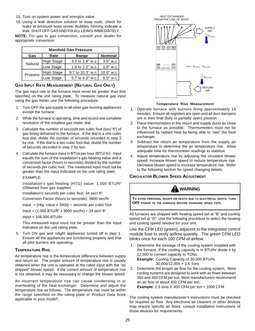
25
15. Turn on system power and energize valve.16. Using a leak detection solution or soap suds, check for
leaks at pressure boss screw. Bubbles forming indicate aleak. SHUT OFF GAS AND FIX ALL LEAKS IMMEDIATELY.
NOTE: For gas to gas conversion, consult your dealer forappropriate conversion.
Gas Rate Range NominalHigh Stage 3.2 to 3.8" w.c. 3.5" w.c.Low Stage 1.6 to 2.2" w.c. 1.9" w.c.High Stage 9.7 to 10.3" w.c. 10.0" w.c.Low Stage 5.7 to 6.3" w.c. 6.0" w.c.
Manifold Gas Pressure
Natural
Propane
GAS INPUT RATE MEASUREMENT (NATURAL GAS ONLY)The gas input rate to the furnace must never be greater than thatspecified on the unit rating plate. To measure natural gas inputusing the gas meter, use the following procedure.
1. Turn OFF the gas supply to all other gas-burning appliancesexcept the furnace.
2. While the furnace is operating, time and record one completerevolution of the smallest gas meter dial.
3. Calculate the number of seconds per cubic foot (sec/ ft3) ofgas being delivered to the furnace. If the dial is a one cubicfoot dial, divide the number of seconds recorded in step 2by one. If the dial is a two cubic foot dial, divide the numberof seconds recorded in step 2 by two.
4. Calculate the furnace input in BTUs per hour (BTU/ hr). Inputequals the sum of the installation’s gas heating value and aconversion factor (hours to seconds) divided by the numberof seconds per cubic foot. The measured input must not begreater than the input indicated on the unit rating plate.EXAMPLE:Installation’s gas heating (HTG) value: 1,000 BTU/ft3
(Obtained from gas supplier)Installation’s seconds per cubic foot: 34 sec/ ft3
Conversion Factor (hours to seconds): 3600 sec/hrInput = (Htg. value x 3600) ÷ seconds per cubic footInput = (1,000 BTU/ft3 x 3600 sec/hr) ÷ 34 sec/ ft3
Input = 106,000 BTU/hrThis measured input must not be greater than the inputindicated on the unit rating plate.
5. Turn ON gas and relight appliances turned off in step 1.Ensure all the appliances are functioning properly and thatall pilot burners are operating.
TEMPERATURE RISE
Air temperature rise is the temperature difference between supplyand return air. The proper amount of temperature rise is usuallyobtained when the unit is operated at the rated input with the “asshipped” blower speed. If the correct amount of temperature riseis not obtained, it may be necessary to change the blower speed.
An incorrect temperature rise can cause condensing in oroverheating of the heat exchanger. Determine and adjust thetemperature rise as follows. The temperature rise must be withinthe range specified on the rating plate or Product Data Bookapplicable to your model*.
RISE =
SUPPLY AIR
RETURN AIR
HEAT EXCHANGERRADIATION "LINE OF SIGHT"
TRETURN
TSUPPLY
TSUPPLY - TRETURN
Temperature Rise Measurement1. Operate furnace with burners firing approximately 15
minutes. Ensure all registers are open and all duct dampersare in their final (fully or partially open) position.
2. Place thermometers in the return and supply ducts as closeto the furnace as possible. Thermometers must not beinfluenced by radiant heat by being able to “see” the heatexchanger.
3. Subtract the return air temperature from the supply airtemperature to determine the air temperature rise. Allowadequate time for thermometer readings to stabilize.
4. Adjust temperature rise by adjusting the circulator blowerspeed. Increase blower speed to reduce temperature rise.Decrease blower speed to increase temperature rise. Referto the following section for speed changing details.
CIRCULATOR BLOWER SPEED ADJUSTMENT
WARNING
TO AVOID PERSONAL INJURY OR DEATH DUE TO ELECTRICAL SHOCK, TURNOFF POWER TO THE FURNACE BEFORE CHANGING SPEED TAPS.
All furnaces are shipped with heating speed set at “B” and coolingspeed set at “D”. Use the following procedure to select the heatingand cooling speed needed for your unit.Use the CFM LED (green), adjacent to the integrated controlmodule fuse to verify airflow quantity. The green CFM LEDblinks once for each 100 CFM of airflow.1. Determine the tonnage of the cooling system installed with
the furnace. If the cooling capacity is in BTU/hr divide it by12,000 to convert capacity to TONs.Example: Cooling Capacity of 30,000 BTU/hr.
30,000/12,000 = 2.5 Tons2. Determine the proper air flow for the cooling system. Most
cooling systems are designed to work with air flows between350 and 450 CFM per ton. Most manufacturers recommendan air flow of about 400 CFM per ton.Example: 2.5 tons X 400 CFM per ton = 1000 CFM
The cooling system manufacturer’s instructions must be checkedfor required air flow. Any electronic air cleaners or other devicesmay require specific air flows, consult installation instructions ofthose devices for requirements.

26
3. Knowing the furnace model, locate the high stage coolingair flow charts in the Product Data Book applicable to yourmodel* . Look up the cooling air flow determined in step 2and find the required cooling speed and adjustment setting.Example: A 70 kBtu furnace is to be installed with a 2.5
ton air conditioning system. The air flowneeded is 1000 CFM. Using the cooling speedchart for the 70 kBtu furnace, find the airflowclosest to 1000 CFM. A cooling airflow of 990CFM can be attained by setting the coolingspeed to “C” and the adjustment to “-” (minus).NOTE: Continuous Fan Speed will be 56% ofhigh stage cooling.
4. Locate the blower speed selection DIP switches on theintegrated control module. Select the desired “cooling”speed tap by positioning switches 1 and 2 appropriately.Select the desired “adjust” tap by positioning switches 3and 4 appropriately. Refer to the following figure for switchpositions and their corresponding taps. Turn off power tofurnace for a minimum of 10 seconds, allowing motor toreset and recognize new speed selection. Turn on powerto furnace. Verify CFM by counting the number of times thegreen CFM LED blinks.
5. The multi-speed circulator blower also offers several customON/OFF ramping profiles. These ramping profiles may beused to enhance cooling performance and increase comfortlevel. The ramping profiles are selected using DIP switches5 and 6. Refer to the following figure for switch positionsand their corresponding taps. Refer to the bullet points belowfor a description of each ramping profile. Turn off power tofurnace for a minimum of 10 seconds, allowing motor toreset and recognize the new profile selection. Turn on powerto the furnace. Verify profile selection by counting the greenCFM LED blinks and timing each step of the ramping profile
• Profile A provides only an OFF delay of 1 minute at 100% ofthe cooling demand airflow.
100% CFM
1 min
100% CFM
Cooling Demand
OFF OFF
• Profile B ramps up to full cooling demand airflow by firststepping up to 50% of the full demand for 30 seconds. Themotor then ramps to 100% of the required airflow. A 1 minuteOFF delay at 100% of the cooling airflow.
OFF 100% CFM
Cooling Demand
100% CFM
1 min
50% CFM OFF
½ min
• Profile C ramps up to 82% of the full cooling demand airflowand operates there for approximately 7 ½ minutes. The motorthen steps up to the full demand airflow. Profile C also hasa 1 minute/100% OFF delay.
100% CFM 100% CFM
1 min
82% CFM
Cooling Demand
7 ½ min
OFF OFF
• Profile D ramps up to 50% of the demand for ½ minute,then ramps to 82% of the full cooling demand airflow andoperates there for approximately 7 ½ minutes. The motor
then steps up to the full demand airflow. Profile D has a 1/2 minute at 50% airflow OFF delay.
100% CFM 50% CFM
½ min
82% CFM
Cooling Demand
7 ½ min
OFF OFF 50% CFM
½ min
Ramping Profiles (*indicates factory setting)
Ramping Profile Tap A
Ramping Profile Tap B
Ramping Profile Tap C
Ramping Profile Tap D
8 7 6 5 4 3 2 1
O F F
O F F
8 7 6 5 4 3 2 1
O F F
O F F
8 7 6 5 4 3 2 1
O F F
O F F
8 7 6 5 4 3 2 1
O F F
O F F
*
6. Select the heating speed from the heating speed chart inthe Product Data Book applicable for your model*. Theadjust setting (already established by the cooling speedselection) determines which set of speeds are available.The selected speed must provide a temperature rise withinthe rise range listed with the particular model.Example: The 70 kBtu is set for 990 CFM on cooling,
the “ADJUST” is set to “-” (minus). The fourheating speeds available are “A Minus”, “BMinus”, “C Minus”, and “D Minus”. “B Minus”has a rise of 56°F for both stages which iswithin the 30-60°F rise range for the 70 kBtu.This setting will keep electrical consumptionto a minimum. Set the “Heat” speed DIPswitches to “A”.
7. Select the desired “heating” speed tap by positioningswitches 7 and 8 appropriately. Refer to figure above. Turnoff power to furnace for a minimum of 10 seconds, allowingmotor to reset and recognize new speed selection. Turn onpower to furnace. Verify selected CFM by counting the greenCFM LED blinks.
In general lower heating speeds will: reduce electrical consumption,lower operating sound levels of the blower, and increase the outletair temperature delivered to the home. The speeds available allowthe blower performance to be optimized for the particularhomeowner’s needs.

27
OFF
OFF
8 7 4 3 2 1
OFF
ON
4 3 2 1
ON
OFF
4 3 2 1
ON
ON
4 3 2 1
CoolingSpeedTap A
CoolingSpeedTap B
CoolingSpeedTap C
CoolingSpeedTap D
*
Cooling Speed Taps(* indicates factory setting)
OFF
OFF
8 7 4 3 2 1
OFF
ON
8 7 4 3 2 1
ON
OFF
8 7 4 3 2 1
ON
ON
8 7 4 3 2 1
HeatingSpeedTap A
HeatingSpeedTap B
HeatingSpeedTap C
HeatingSpeedTap D
Heating Speed Taps(* indicates factory setting)
*OFF
OFF
8 7 4 3 2 1
OFF
ON
8 7 4 3 2 1
ON
OFF
8 7 4 3 2 1
Normal
+ (Plus)Adjust
- (Minus)Adjust
Adjust Taps(* indicates factory setting)
*8 7
8 7
8 7
ADJUST BLOWER HEAT OFF DELAY
The integrated control module provides a selectable heat off delayfunction. The heat off delay period may be set to 90, 120, 150,180seconds using the DIP switches or jumper provided on the controlmodule. The delay is factory shipped at 150 seconds but may bechanged to suit the installation requirements and/or homeownerpreference. Refer to the following figures for switch positions andcorresponding delay times.
Heat OffDelay
90 SecondsONON 1
23
Heat OffDelay
120 Seconds
Heat OffDelay
150 Seconds
Heat OffDelay
180 Seconds
ON
OFF
123
ON 123
123
OFFOFF
Heat Off Delay(* indicates factory setting)
*
OFF
Heat Off Delay
CIRCULATOR BLOWER FAN TIMING ADJUSTMENT
NOTE: Items in this section refer to the air circulator blower fan,NOT to the induced draft blower. The induced draft blower timingsequence is not adjustable. The circulator blower fan timing isadjustable only on models with optional “heating fan OFF delay”adjustment pins or switches (Figure 28). It is NOT adjustable inany other circumstances.
As shipped, the circulator blower fan will remain on for 150seconds after the gas valve closes. The circulator blower thenramps down to “OFF” during the 30 seconds following the heat offdelay period. When a call for cooling occurs, the circulator fancomes on and remains on for 45 seconds after the call for coolingends. During normal heating operation, the circulator fan will comeon approximately 34 seconds after the gas valve opens.
ON
OFF ON
OFF
ON
OFF ON
OFF
1
2
1
2
1
2
1
2
90SECONDDELAY
120SECON DDELAY
150SECON DDELAY
180SECON DDELAY
Switches viewed in an upflow installation.
Adjustment Switches
XIII. OPERATIONAL CHECKS
WARNING
TO AVOID PERSONAL INJURY OR DEATH, DO NOT REMOVE ANY INTERNALCOMPARTMENT COVERS OR ATTEMPT ANY ADJUSTMENT. ELECTRICALCOMPONENTS ARE CONTAINED IN BOTH COMPARTMENTS. CONTACT AQUALIFIED SERVICE AGENT AT ONCE IF AN ABNORMAL FLAME APPEARANCESHOULD DEVELOP.
BURNER FLAME
The burner flames should be inspected with the burnercompartment door installed. Flames should be stable, quiet,soft, and blue (dust may cause orange tips but they must not beyellow). Flames should extend directly outward from the burnerswithout curling, floating, or lifting off. Flames must not impinge onthe sides of the heat exchanger firing tubes.
Check the burner flames for: 1. Good adjustment2. Stable, soft and blue 3. Not curling, floating, or lifting off.
Burner Flame
AUXILIARY LIMIT CONTROL
Auto reset limits are located on or near the blower. To access thisauxiliary limit, disconnect the electrical power and remove the blowerdoor. If the limit control opens, the air circulation blower will runcontinuously. The diagnostic light will flash one time. The auxiliarylimit control is designed to prevent furnace operation in case ofmain blower failure on horizontal and counterflow installations. Itmay also open if the power supply is interrupted while the furnaceis firing. The auxiliary limit control is suitable for both horizontalright and horizontal left installations. Regardless of airflow direction,it does not need to be relocated.
WARNING
TO AVOID PERSONAL INJURY OR DEATH, DO NOT REMOVE ANY INTERNALCOMPARTMENT COVERS OR ATTEMPT ANY ADJUSTMENT. ELECTRICALCOMPONENTS ARE CONTAINED IN BOTH COMPARTMENTS. TO PREVENTPROPERTY DAMAGE, PERSONAL INJURY OR DEATH DUE TO EXPLOSION AND/OR FIRE, CONTACT A QUALIFIED SERVICE AGENT AT ONCE IF AN ABNORMAL FLAME APPEARS.

28
PRIMARY LIMIT
The primary limit control guards against overheating resultingfrom insufficient conditioned air passing over the heat exchanger.If the primary limit control does not function during this test, thecause must be determined and corrected. Function of this controlshould be verified by gradually blocking the furnace return air afterthe furnace has been operating (burners firing) for approximatelyten minutes. Check the control as follows:
1. Allow the furnace to operate with burners firing continuouslyfor approximately ten minutes.
2. Gradually block the return air to furnace. Remove airflowblockage when limit control is activated and turns off burners.Airflow blockage causes unit overheating and will producethe following reactions:
• The gas valve to close and extinguish flame,• The induced draft blower to be de-energized after a fifteen
second postpurge, and• The circulator blower to remain energized continuously until
limit control resets.3. Remove the return air blockage to clear overheating
condition. After an acceptable temperature is reachedduring the cool down period, the limit control will reset andallow the furnace to resume normal operation.
WARNING
TO PREVENT PREMATURE FAILURE OF HEAT EXCHANGER, PROPERTY DAMAGE,PERSONAL INJURY OR DEATH, DO NOT ADJUST THE LIMIT CONTROL (FACTORYSET).
XIV. SAFETY CIRCUIT DESCRIPTION
IMPORTANT NOTE: This unit must not be used as a constructionheater during the finishing phases of construction of a new structure.This type of use may result in premature failure due to extremelylow return air temperatures and exposure to corrosive or very dirtyatmospheres.
These checks establish that the primary limit control is functioningand will respond to a restriction in the return air, or a circulatorblower failure. If the primary limit control does not function duringthis test, the cause must be determined and corrected.
GENERAL
A number of safety circuits are employed to ensure safe and properfurnace operation. These circuits serve to control any potentialsafety hazards and serve as inputs in the monitoring and diagnosisof abnormal function. These circuits are continuously monitoredduring furnace operation by the integrated control module.
INTEGRATED CONTROL MODULE
The integrated control module is an electronic device which controlsall furnace operations. Responding to the thermostat, the moduleinitiates and controls normal furnace operation, and monitors andaddresses all safety circuits. If a potential safety concern isdetected, the module will take the necessary precautions andprovide diagnostic information through an LED.
PRIMARY LIMIT
The primary limit control is located on the partition panel andmonitors heat exchanger compartment temperatures. It is anautomatic reset, temperature sensor. The limit guards against theoverheating as a resulting of insufficient air passing over the heatexchanger.
AUXILIARY LIMIT
The auxiliary limit control is located either on or near the circulatorblower and monitors heat exchanger compartment temperatures.The control is a temperature sensor. It guards against overheatingresulting from insufficient air passing over the heat exchanger.
ROLLOUT LIMITS
The rollout limit controls are mounted on the burner/manifoldassembly and monitor the burner flame. They are manual-reset,temperature sensors. This limit guards against burner flames notbeing properly drawn into the heat exchanger.
PRESSURE SWITCHES
The pressure switches are normally-open, negative air pressure-activated switches. They monitor the airflow (combustion air andflue products) through the heat exchanger via pressure taps locatedon the induced draft blower. These switches guard againstinsufficient airflow (combustion air and flue products) through theheat exchanger.
FLAME SENSOR
The flame sensor is a probe mounted to the burner/manifoldassembly which uses the principle of flame rectification to determinethe presence or absence of flame.
XV. TROUBLESHOOTING
ELECTROSTATIC DISCHARGE (ESD) PRECAUTIONS
NOTE: Discharge body’s static electricity before touching unit. Anelectrostatic discharge can adversely affect electrical components.
Use the following precautions during furnace installation andservicing to protect the integrated control module from damage.By putting the furnace, the control, and the person at the sameelectrostatic potential, these steps will help avoid exposing theintegrated control module to electrostatic discharge. This procedureis applicable to both installed and uninstalled (ungrounded)furnaces.
1. Disconnect all power to the furnace. Do not touch theintegrated control module or any wire connected to thecontrol prior to discharging your body’s electrostatic chargeto ground.
2. Firmly touch a clean, unpainted, metal surface of the furnaceaway from the control. Any tools held in a person’s handduring grounding will be discharged.
3. Service integrated control module or connecting wiringfollowing the discharge process in step 2. Use caution notto recharge your body with static electricity; (i.e., do not moveor shuffle your feet, do not touch ungrounded objects, etc.).If you come in contact with an ungrounded object, repeatstep 2 before touching control or wires.
4. Discharge your body to ground before removing a newcontrol from its container. Follow steps 1 through 3 ifinstalling the control on a furnace. Return any old or newcontrols to their containers before touching any ungroundedobject.
DIAGNOSTIC CHART
WARNING
TO AVOID ELECTRICAL SHOCK, INJURY OR DEATH, DISCONNECT ELECTRICALPOWER BEFORE PERFORMING ANY SERVICE OR MAINTENANCE.

29
Refer to the troubleshooting chart on the following pages forassistance in determining the source of unit operational problems.The red diagnostic LED blinks to assist in troubleshooting the unit.The number of blinks refer to a specific code.
RESETTING FROM LOCKOUT
Furnace lockout results when a furnace is unable to achieveignition after three attempts, or when it has lost flame five timesduring a single call for heat. It is characterized by a non-functioningfurnace and a one flash diagnostic LED code from the red LED. Ifthe furnace is in “lockout”, it will (or can be) reset in any of thefollowing ways.
1. Automatic reset. The integrated control module willautomatically reset itself and attempt to resume normaloperations following a one hour lockout period.
2. Manual power interruption. Interrupt 115 volt power to thefurnace for 1 - 20 seconds.
3. Manual thermostat cycle. Lower the thermostat so thatthere is no longer a call for heat for 1 -20 seconds thenreset to previous setting.
NOTE: If the condition which originally caused the lockout stillexists, the control will return to lockout. Refer to the DiagnosticChart for aid in determining the cause.
XVI. MAINTENANCE
WARNING
TO AVOID ELECTRICAL SHOCK, INJURY OR DEATH, DISCONNECT ELECTRICALPOWER BEFORE PERFORMING ANY MAINTENANCE. IF YOU MUST HANDLE THEIGNITER, HANDLE WITH CARE. TOUCHING THE IGNITER ELEMENT WITH BAREFINGERS, ROUGH HANDLING, OR VIBRATION COULD DAMAGE THE IGNITERRESULTING IN PREMATURE FAILURE. ONLY A QUALIFIED SERVICER SHOULDEVER HANDLE THE IGNITER.
ANNUAL INSPECTION
The furnace should be inspected by a qualified installer, or serviceagency at least once per year. This check should be performed atthe beginning of the heating season. This will ensure that all furnacecomponents are in proper working order and that the heating systemfunctions appropriately. Pay particular attention to the followingitems. Repair or service as necessary.
• Flue pipe system. Check for blockage and/or leakage.Check the outside termination and the connections at andinternal to the furnace.
• Heat exchanger. Check for corrosion and/or buildup withinthe heat exchanger passageways.
• Burners. Check for proper ignition, burner flame, and flamesense.
• Wiring. Check electrical connections for tightness and/orcorrosion. Check wires for damage.
• Filters.
FILTERS
WARNING
TO AVOID PROPERTY DAMAGE, PERSONAL INJURY OR DEATH, DISCONNECTELECTRICAL POWER BEFORE REMOVING FILTERS. NEVER OPERATE FURNACEWITHOUT A FILTER INSTALLED BECAUSE DUST AND LINT WILL BUILD UP ONINTERNAL PARTS RESULTING IN LOSS OF EFFICIENCY, EQUIPMENT DAMAGEAND POSSIBLE FIRE.
A return air filter is not supplied with this furnace; however, theremust be a means of filtering all of the return air. The installer willsupply filter(s) at the time of installation.
FILTER MAINTENANCE
Improper filter maintenance is the most common cause ofinadequate heating or cooling performance. Filters should becleaned (permanent) or replaced (disposable) every two monthsor as required. When replacing a filter, it must be replaced with afilter of the same type and size.
WARNING
TO PREVENT PROPERTY DAMAGE, PERSONAL INJURY OR DEATH DUE TOELECTRICAL SHOCK, DISCONNECT ELECTRICAL POWER TO THE FURNACEBEFORE REMOVING THE FILTER OR PERFORMING ANY OTHER MAINTENANCE.
Become familiar with filter location and procedures for removal,cleaning and replacing them. If help is needed, contact the installerof the furnace or a qualified servicer.
FILTER REMOVAL
Depending on the installation, differing filter arrangements can beapplied. Filters can be installed in either the central return registeror a side panel external filter rack (upflow only). A media air filter orelectronic air cleaner can be used as an alternate filter. Follow thefilter sizes given in the Recommended Minimum Filter size table toensure proper unit performance.
To remove filters from an external filter rack in an upright upflowinstallation, follow the directions provided with external filter rackkit. To remove internal filters see Internal Filter Removal section.Internal filters are an accessory item and are not included withyour furnace. For further details, see your distributor.
UPRIGHT FILTER REMOVAL
To remove filters from an external filter rack in an upright upflowinstallation, follow the directions provided with external filter rackkit.
Clean, wash and dry a permanent filter. When using a metal filter,both sides should be sprayed with a dust adhesive as recommendedon adhesive container. Spray adhesives for use with permanentmetal filters can be found at some hardware stores. BE SUREAIRFLOW DIRECTION ARROW POINTS TOWARDS THEBLOWER.
Inspect filter. If your dirty filter is the disposable type, replace dirtywith the same type and size filter. If your dirty filter is a permanentmetal filter, clean as follows:
• Wash, rinse, and dry the permanent filters. Both sides shouldthen be sprayed with a filter adhesive as is recommendedon the adhesive container. Many hardware stores stockspray adhesives for use with permanent filters.
• If badly torn or uncleanable, these filters must be replacedby equal size permanent, high velocity filters. Throwawayfilters must not be used as replacement for permanent filters.Under normal use, permanent filters should last for severalyears.
INDUCED DRAFT AND CIRCULATOR BLOWER MOTORS
The bearings in the induced draft blower and circulator blowermotors are permanently lubricated by the manufacturer. No furtherlubrication is required. Check motor windings for accumulation ofdust which may cause overheating. Clean as necessary.
30
FLAME SENSOR (QUALIFIED SERVICER ONLY)Under some conditions, the fuel or air supply can create a nearlyinvisible coating on the flame sensor. This coating acts as aninsulator causing a drop in the flame sense signal. If the flamesense signal drops too low the furnace will not sense flame andwill lock out. The flame sensor should be carefully cleaned by aqualified servicer using emery cloth or steel wool. Followingcleaning, the flame sense signal should be as indicated in theSpecifications Sheet.
IGNITER (QUALIFIED SERVICER ONLY)If the igniter and the surrounding air are at about 70°F and theigniter wires are not connected to any other electrical components,the resistance of the igniter should not exceed 75 ohms. If it does,the igniter should be replaced.
BURNERS
WARNING
TO PREVENT PERSONAL INJURY OR DEATH, DO NOT REMOVE ANY INTERNALCOMPARTMENT COVERS OR ATTEMPT ANY ADJUSTMENT. ELECTRICALCOMPONENTS ARE CONTAINED IN BOTH COMPARTMENTS. CONTACT A QUALIFIED SERVICE AGENT AT ONCE IF AN ABNORMAL FLAME APPEARANCESHOULD DEVELOP.
Periodically during the heating season make a visual check of theburner flames. Turn the furnace on at the thermostat. Wait a fewminutes, since any dislodged dust will alter the normal flameappearance. Flames should be stable, quiet, soft and blue withslightly orange tips. They should not be yellow. They shouldextend directly outward from the burner ports without curlingdownward, floating or lifting off the ports.
CLEANING (QUALIFIED SERVICER ONLY)
1. Shut off electric power and gas supply to the furnace.2. Remove screws securing manifold to burner bracket.
Slightly pull manifold out and away from burner bracket.Burners will drop. Re-secure manifold to burner bracket.
3. Tilt burners to slotted side of burner bracket. Rotate burnersclockwise to remove.
4. Use bottle brush to clean burner insert and inside of burner.5. Replace burner (opposite of removal). Ensure burners
are fully seated on burner bracket tabs and are properlyaligned.
6. Turn on electric power and gas supply to the furnace.7. Check furnace for proper operation. Refer to “Operational
Checks” section to verify burner flame characteristics.
XVII. BEFORE LEAVING AN INSTALLATION
• Cycle the furnace with the thermostat at least three times.Verify cooling and fan only operation.
• Review the Owner’s Manual with the homeowner anddiscuss proper furnace operation and maintenance.
• Leave literature packet near furnace.
XVIII. REPAIR AND REPLACEMENT PARTS
• When ordering any of the listed functional parts, be sure toprovide the furnace model, manufacturing, and serialnumbers with the order.
• Although only functional parts are shown in the parts list,all sheet metal parts, doors, etc. may be ordered bydescription.
• Parts are available from your distributor.Functional Parts List-
Single Stage Gas Valve Blower/Box GasketNatural Gas Orifice Rollout Limit SwitchPropane Gas Orifice Auxiliary Limit SwitchBurner Heat ExchangerHot Surface Igniter Door SwitchFlame Sensor TransformerGas Manifold Blower WheelIgnition Control Blower HousingBlower Mounting Bracket Blower CutoffPressure Switch Blower MotorPressure Switch Hose Motor Mount BracketInduced Draft Blower CapacitorCollector Box
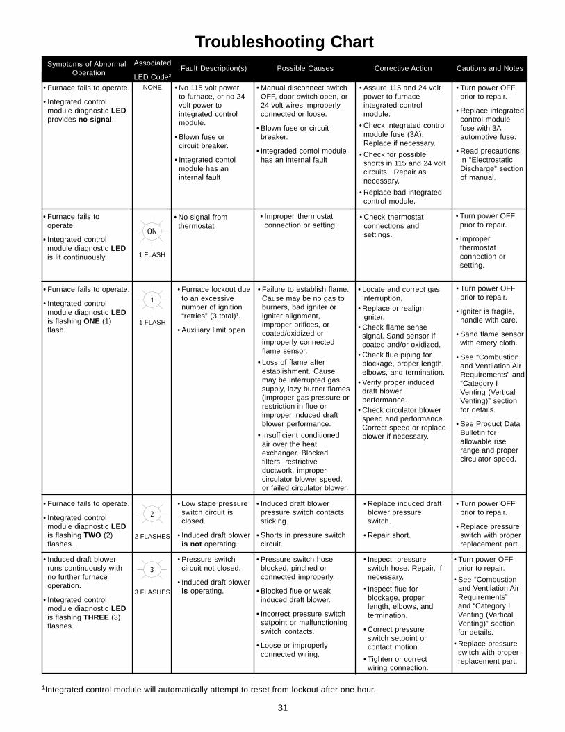
31
1Integrated control module will automatically attempt to reset from lockout after one hour.
Troubleshooting Chart
• Furnace lockout dueto an excessivenumber of ignition“retries” (3 total)1.
• Auxiliary limit open
• Locate and correct gasinterruption.
• Replace or realignigniter.
• Check flame sensesignal. Sand sensor ifcoated and/or oxidized.
• Check flue piping forblockage, proper length,elbows, and termination.
• Verify proper induceddraft blowerperformance.
• Check circulator blowerspeed and performance.Correct speed or replaceblower if necessary.
• Turn power OFFprior to repair.
• Igniter is fragile,handle with care.
• Sand flame sensorwith emery cloth.
• See “Combustionand Ventilation AirRequirements” and“Category IVenting (VerticalVenting)” sectionfor details.
• See Product DataBulletin forallowable riserange and propercirculator speed.
• Furnace fails to operate.
• Integrated controlmodule diagnostic LEDis flashing ONE (1)flash.
1
1 FLASH
• Failure to establish flame.Cause may be no gas toburners, bad igniter origniter alignment,improper orifices, orcoated/oxidized orimproperly connectedflame sensor.
• Loss of flame afterestablishment. Causemay be interrupted gassupply, lazy burner flames(improper gas pressure orrestriction in flue orimproper induced draftblower performance.
• Insufficient conditionedair over the heatexchanger. Blockedfilters, restrictiveductwork, impropercirculator blower speed,or failed circulator blower.
• Low stage pressureswitch circuit isclosed.
• Induced draft bloweris not operating.
• Replace induced draftblower pressureswitch.
• Repair short.
• Turn power OFFprior to repair.
• Replace pressureswitch with properreplacement part.
• Furnace fails to operate.
• Integrated controlmodule diagnostic LEDis flashing TWO (2)flashes.
2
2 FLASHES
• Induced draft blowerpressure switch contactssticking.
• Shorts in pressure switchcircuit.
• Inspect pressureswitch hose. Repair, ifnecessary,
• Inspect flue forblockage, properlength, elbows, andtermination.
• Correct pressureswitch setpoint orcontact motion.
• Tighten or correctwiring connection.
• Pressure switch hoseblocked, pinched orconnected improperly.
• Blocked flue or weakinduced draft blower.
• Incorrect pressure switchsetpoint or malfunctioningswitch contacts.
• Loose or improperlyconnected wiring.
• Pressure switchcircuit not closed.
• Induced draft bloweris operating.
• Induced draft blowerruns continuously withno further furnaceoperation.
• Integrated controlmodule diagnostic LEDis flashing THREE (3)flashes.
3
3 FLASHES
• Turn power OFFprior to repair.
• See “Combustionand Ventilation AirRequirements”and “Category IVenting (VerticalVenting)” sectionfor details.
• Replace pressureswitch with properreplacement part.
• No 115 volt powerto furnace, or no 24volt power tointegrated controlmodule.
• Blown fuse orcircuit breaker.
• Integrated contolmodule has aninternal fault
• Manual disconnect switchOFF, door switch open, or24 volt wires improperlyconnected or loose.
• Blown fuse or circuitbreaker.
• Integraded contol modulehas an internal fault
• Assure 115 and 24 voltpower to furnaceintegrated controlmodule.
• Check integrated controlmodule fuse (3A).Replace if necessary.
• Check for possibleshorts in 115 and 24 voltcircuits. Repair asnecessary.
• Replace bad integratedcontrol module.
• Turn power OFFprior to repair.
• Replace integratedcontrol modulefuse with 3Aautomotive fuse.
• Read precautionsin “ElectrostaticDischarge” sectionof manual.
• Furnace fails to operate.
• Integrated controlmodule diagnostic LEDprovides no signal.
NONE
Fault Description(s) Possible Causes Corrective Action Cautions and NotesSymptoms of AbnormalOperation
Associated
LED Code2
• Furnace fails tooperate.
• Integrated controlmodule diagnostic LEDis lit continuously.
ON
1 FLASH
• No signal fromthermostat
• Improper thermostatconnection or setting.
• Check thermostatconnections andsettings.
• Turn power OFFprior to repair.
• Improperthermostatconnection orsetting.

32
Troubleshooting ChartFault Description(s)Symptoms of Abnormal
Operation
4
4 FLASHES
Associated
LED Code2
• Circulator blower runscontinuously. No furnaceoperation.
• Integrated control modulediagnostic LED is flashingFOUR (4) flashes.
7
7 FLASHES
• Normal furnaceoperation.
• Integrated controlmodule diagnostic LEDis flashing SEVEN (7)flashes.
• Furnace fails to operate.• Integrated control module
diagnostic LED is flashingcontinuously.
C
CONTINUOUS
FLASHING
• Primary limitcircuit is open.
• Polarity of 115volt power isreversed.
• Flame sensemicroamp signal islow.
• Insufficient conditioned airover the heat exchanger.Blocked filters, restrictiveductwork, impropercirculator blower speed,or failed circulator blower.
• Flame rollout.• Misaligned burners,
blocked flue and/or airinlet pipe, or failedinduced draft blower.
• Loose or improperlyconnected wiring.
Possible Causes Corrective Action Cautions and Notes
• Check filters andductwork for blockage.Clean filters or removeobstruction.
• Check circulator blowerspeed and performance.Correct speed or replaceblower if necessary.
• Check burners for properalignment.
• Check flue and air inletpiping for blockage,proper length, elbows,and termination. Correctas necessary.
• Check induced draftblower for properperformance. Replace, ifnecessary.
• Tighten or correct wiringconnection.
• Turn power OFFprior to repair.
• See Product DataBulletin forallowable riserange and propercirculator speed.See “Vent/FluePipe” section forpiping details.
• Replace pressureswitch with properreplacement part.
• Polarity of 115 volt ACpower to furnace orintegrated control moduleis reversed.
• Poor unit ground.
• Flame sensor is coated/oxidized.
• Flame sensor incorrectlypositioned in burnerflame.
• Lazy burner flame due toimproper gas pressure orcombustion air.
• Review wiring diagram tocorrect polarity.
• Verify proper ground.Correct if necessary.
• Check and correct wiring.
• Sand flame sensor iscoated/oxidized.
• Inspect for proper sensoralignment.
• Check inlet air piping forblockage, proper length,elbows, and termination.
• Compare current gaspressure to rating plateinfo. Adjust as needed.
• Turn power OFFprior to repair.
• Turn power OFFprior to repair.
• Sand flamesensor withemery clot.
• See “Vent/FluePipe” section forpiping details.
• See rating platefor proper gaspressure.
• Inspect pressure switchhose. Repair, if necessary.
• Inspect flue and/or inletair piping for blockage,proper length, elbows,and termination. Checkdrain system. Correct asnecessary.
• Correct pressure switchsetpoint or contactmotion.
• Tighten or correct wiringconnection.
9
9 FLASHES
• Furnace not operating.
• Integrated control modulediagnostic LED is flashingEIGHT (8) flashes.
• Furnace operating onlow stage gas with highstage induced draft blower
• High stage circulatorblower (temperature, ofconditioned air, lower thantypical).
• Integrated control modulediagnostic LED is flashingNINE (9) flashes.
8
8 FLASHES
• High stagepressure switchcircuit does notclose in responseto high stageinduced draftblower operation.
• Problem withigniter circuit.
• Improperlyconnected igniter
• Bad igniter
• Poor unit ground
• Pressure switch hoseblocked, pinched orconnected improperly.
• Blocked flue and/or inlet airpipe, blocked drain system,or weak induced draftblower.
• Incorrect pressure switchsetpoint or malfunctioningswitch contacts.
• Loose or improperlyconnected wiring.
• Check and correct wiringfrom integrated controlmodule to igniter
• Replace bad igniter
• Check and correct unitground wiring
• Turn power OFFprior to repair.
• Replace igniterwith propersilicon nitridereplacement part.
• Turn power OFFprior to repair.
• Replace pressureswitch withproperreplacement part.
• Integrated control modulediagnostic LED is flashingFIVE (5) times.
• Induced draft blower andcirculator blower runcontinuously. No furnaceoperation.
• Flame sensed withno call for heat.
• Correct short at flamesensor or in flamesensor wiring.
• Check for lingeringflame
• Verify proper operationof gas valve
• Short to ground in flamesense circuit.
• Lingering burner flame.• Slow closing gas valve
• Turn power OFFprior to repair.5
5 FLASHES

33
Wiring Diagram
AUTO RESETFUS E 3 A
YL
24 VA CPR
D R AFT P R ES S U RE S W ITC H
IN T EG RAT ED CO N TR O L9
3. IF A NY O F TH E O R IG INA L W IRE AS SU PP LIED W IT H TH E F UR N A CE M U ST BE
4. U NIT M U ST BE PER M AN ENT LY G R O UN DED A N D CO N FO R M T O N .E .C . AN D LO CAL CO D ES .
2 . M AN U FAC TU RER 'S SPE C IF IED R E PLAC EM EN T PAR T S M UST B E US ED W HEN SER VICING .
R E PLAC ED, IT M U ST BE R EP LACED W IT H W IRING M AT E RIAL HAVING A T EM PER ATU RE
1. SET H E AT ANT IC IPAT O R O N RO O M T H ER M O ST AT AT 0 .7 AM PS .
R A T IN G O F A T LEAS T 105
B 14933257 R EV .0 0
C O LO R CO D E S:YL YE LLO W
G N G R EE NBK BLACK
O R O R AN G EPR P U R PLE
C
R D RED
BR B R O W NW H W H IT E
G Y G RAYBU B LU E
PK P IN K N O TE S:
O V ERC UR REN TPR O T. D EVIC E
°C. U SE C O PPER CO N D U C TO R S O N LY.
P LU G C O NN ECT IO N
R OLL O U T L IM ITS C O N TR O L
SYSTEM LOCKOUT (RETRIES/RECYCLES EXCEEDED)
4
6
8
7
1
2
3
0
IGN IT ORS U RFA CE
FLA M E
H OT
S EN S OR
G N D
WH
BK
2 S TA G EG A S V A LV E
BR
B U
OR
Y L
R D
B LO W ER
24V HUMIDIFIER
H IGH F IREP R ES S UR E S W ITC H
SW IT CH (PR ESS.)
SW IT CH (T EM P.)
F IE LD G N D
EQ U IP M ENT G N D
F IE LD SP LICE
LO W VO LT AG E F IELD
INT E R N AL TO
H I V O LTAG E FIE LD
JU N CT IO N
T ERM IN AL
H I VO LTAG E (115V)
LO W V O LT AG E (24V )
IN TE GR ATE D C ON T R OL M O D U LE
TR (9)
M V C (8 )
GN D (10)
IG N ITER
V AL V EGA S
G N D
C
MANUAL RESET ROLLOUTLIMIT CONTROL(S)
24V H U M .M IC ROY
24V THERMOSTAT CONNECTIONS
C
P R
G
M V L(7 )
P S2 (2 )
M V H (1 )
C
P S1 (1 2)
AUXILIARY LIMITCONTROLS
Y L O
W 2
W 1
LIM IT CO N TRO L
P R
P R IM A R Y
B R
H L1 (6 )
T O
H LO (11)
N O
P M
H I
P R ES S U R ES W ITC H
LO W FIRE
C
N O
PRIMARY LIMITCONTROL
WIRING TO UNITMUST BE PROPERLY
ON SO M E M O D ELSIN DU C T OR C O IL
P R ES S U RE S W ITCH
LO W FIR E
Y L
R D
BK
W H
IN DU C E D
B R
G N D
WH
WH
BK
BR
RD
GN
BUBR
W H
A UXILIA R YLIM IT C O NTR O LS
R DB U
W H
VAC115
VAC24
PR
B K
RDOR
YL
YL
BK
E AC -NE AC -HE LE C TR O N IC
INTEGRATED CONTROL MODULE
INTEGRATED CONTROL MODULE
A IR C LE A N ER
H U M IDIF IE R
H O T S U R FA C E
11 5 V A C
R
24
H U M .V AC .
T H (5)
X FM R -H
F P (3)IG N ITE R
FLA M E S E N SOR
H I F IRE
BLO W E R C O M P AR TM EN T
BUR N ER C O M PA RTM E NT
B LW R
IND L O
H U M -H
IG N -H
IND H I
ID
X FM R -N
TRA NS FO R M E R40 VA
HU M -N
IGN -N
IN D-N
C IRC U LAT OR
JUN C TION BO X
IN DU CT OR C O IL
GN D
B K
B LW R
LIN E -H
70 kB TU ,90kB T U,11 5k BTU M O DE LS
ON LYIN DO OR
A IR
POLARIZED ANDGROUNDED.
B LO W ERC IRC U LATO R
D OO RS W ITCH
LIN E -N
GN D
DISCO N N E C T
31 2
B U
10 1211
64 5
97 8
P R
RD
B R
W H 16 W IR E HA R N E SS
24 VA C . H UM .
O VE R CU RR E NT PR O TE C TIO N D EVICEØ /60 HZ PO W E R SUP PLY W ITH
DISCONNECT POWERBEFORE SERVICING.
T O 115VAC / 1
B K
WARNING:L G N D
B OX
LIN E -N
LIN E H
G ND
JU N C TIO N
N
D O O R S W IT C H
W
W
BK
B K
DE VICEOV ER CU R R E N T P ROT E C TIONP O W E R SU P P LY W ITHTO 1 15 V A C / 1 /6 0H Z
9 F LASHE S = H IG H FIRE PR ESS UR E S W IT CH ST UC K O PEN
C O N TINU O US FLASH E S = 1 15 VO LT A C PO W ER RE VER SE D
8 F LASHE S = CH E CK IG NITER O R IM PR O PER G RO U ND IN G
5 F LASHE S = FLAM E S ENSED W IT H G AS VALVE DE-E N ERG IZED
3 F LA SHES = LO W FIRE P R ESSUR E SW IT CH S T UC K O PEN
2 F LASHE S = LO W FIRE PR ES SUR E SW IT CH ST UC K C LO SED
S TEA D Y O N = N O RM A L O PER AT IO N
4 F LA SHES = TH ERM AL PRO T ECT IV E DE VICE O PEN
7 F LASHE S = LO W FLA M E SE NSE S IG N AL
1 F LASH =
1 2 3PM C H I
3
2
1
H OT
L E DD IA GN OS TIC
EAC
LINE
N E U TR AL
5
4
XFMR
HUM
CIRC
LINE
XFMR
HUM
EAC
N ON O
CC
C
N O
FUSE TWIN/
DEHUM
2
3
1
24 V THE R M O S T AT C O NN E C T ION S
G
16 PINP LU G
B/C
YLO
O Y R W2
W1
TO A
VO
ID P
OS
SIB
LE E
LEC
TRIC
AL
SH
OC
K, P
ER
SO
NA
L IN
JUR
Y,
OR
DE
ATH
, DIS
CO
NN
EC
T TH
E P
OW
ER
BE
FOR
E S
ER
VIC
ING
.W
AR
NIN
G!

34
NOTE: SPECIFICATIONS AND PERFORMANCE DATA LISTED HEREINARE SUBJECT TO CHANGE WITHOUT NOTICE
Quality Makes the Difference!All of our systems are designed and manufactured with the same high quality standards regardless of size orefficiency. We have designed these units to significantly reduce the most frequent causes of product failure.They are simple to service and forgiving to operate. We use quality materials and components. Finally, everyunit is run tested before it leaves the factory. That’s why we know. . . There’s No Better Quality.
Visit our website at www.goodmanmfg.com or www.amana-hac.com for information on:
• Products• Warranties• Customer Services• Parts• Contractor Programs and Training• Financing Options
Goodman Manufacturing Company, L.P.2550 North Loop West, Suite 400, Houston, TX 77092
www.goodmanmfg.com© 2004-2006 Goodman Manufacturing Company, L.P.