installation & operation manual - energylogic
TRANSCRIPT

Installation & Operation Manual
Multi-Fuel Waste-Oil Heater Model 75H
115V/60Hz
Designed to save. Built to last.™
4109 Capital Circle Janesville, WI 53546 www.energylogic.com
1-800-351-0643
Item #: 98030118 Rev. C Issue Date: 30 March 2021


i Call 1-800-351-0643 for Technical Support
Before You Begin…
Caution! Before you begin installation and operation of your heater, read this manual completely,
and save it for future reference! IMPROPER INSTALLATION, OPERATION, OR
MAINTENANCE OF THE HEATER SYSTEM CAN CREATE HAZARDOUS CONDITIONS AND WILL VOID THE
WARRANTY • This heater is UL listed for commercial and industrial use only. • Refer to safety information and precautions in this manual. • Installation of the unit shall be made in accordance with all state and local codes which
may differ from information provided in this manual. Installations in Canada shall be in accordance with the regulations of authorities having jurisdiction and installation practice shall be made according to CSA standard B139, Installation Code for Oil Burning Equipment.
• Product improvements are occurring regularly, so the products may vary slightly from what is shown in this manual.
• If you have any questions or concerns during the installation or operation of the heater, contact your local service representative or EnergyLogic.
Thank you for purchasing an EnergyLogic heater. Record your Unit I.D. number below for future reference. Please register your unit to activate the warranty by visiting EnergyLogic’s website at www.energylogic.com/register . If you have any issues with registering, please contact us at the number below.
Unit I.D. #: (Number located on the side of the cabinet)
Installed By: (Service Company, Address, Contact Name, Phone Number)
Date of Installation:

Call 1-800-351-0643 for Technical Support
Table of Contents
Before You Begin… ........................................................................................................................ i 1. Safety, Codes and Regulations .................................................................................. 1
1.1 General Warnings ........................................................................................................... 1
1.2 Safety Hazards................................................................................................................ 2
1.3 Codes and Regulations ................................................................................................... 4
1.4 Fuels and Fuel Management ........................................................................................... 5
1.5 Clearances to Combustible Surfaces .............................................................................. 6 2. Installation .................................................................................................................... 7
2.1 Technical Guidelines ....................................................................................................... 7
2.2 Heater Placement ........................................................................................................... 7
2.3 Drain Valve Installation ................................................................................................... 8 3. Exhaust Flue System Installation .............................................................................. 9
3.1 Barometric Damper Tee Installation ................................................................................ 9
3.2 Flue Piping Installation .................................................................................................... 9
3.3 Draft Gauge Installation................................................................................................. 12 4. Electrical System Installation ................................................................................... 13
4.1 Wall Thermostat (Standard) .......................................................................................... 13
4.2 Main Electrical Connection ............................................................................................ 14 5. Startup and Operation ............................................................................................... 15
5.1 Do’s and Don’ts/Tech Tips ............................................................................................ 15
5.2 Burner Primary Control Operation ................................................................................. 15
5.3 Safety Systems and Warnings ...................................................................................... 16
5.4 Heater Startup ............................................................................................................... 17
5.4.1 Priming and Starting the Heater .................................................................................... 17
5.4.2 Burner System Checkout .............................................................................................. 18
5.5 Everyday Operation of Your Used Oil Heater ................................................................ 21 6. Maintenance ................................................................................................................ 22
6.1 Service Contracts .......................................................................................................... 22
6.2 Safety Warnings – Lockout/Tagout ................................................................................ 22
6.3 Monitoring System Performance over Time ................................................................... 22

Call 1-800-351-0643 for Technical Support
6.4 Maintenance Procedures .............................................................................................. 23
6.4.1 Heat Exchanger Cleaning ............................................................................................. 24
6.4.2 Fan Cleaning ................................................................................................................. 26
6.4.3 Nozzle Line Assembly Cleaning .................................................................................... 27
6.4.4 Air Compressor Maintenance ........................................................................................ 31
6.4.5 Oil Filter Cleaning.......................................................................................................... 33 7. Troubleshooting ......................................................................................................... 34 8. Appendices ................................................................................................................. 36
8.1 Wiring Diagram ............................................................................................................. 36
8.2 Primary Control Instructions .......................................................................................... 38
8.3 Chimney Flue Installation Instructions ........................................................................... 42
8.4 Heater Specifications .................................................................................................... 46
8.5 75H Heater Maintenance Schedule and Log ................................................................. 47
8.6 Limited Warranty ........................................................................................................... 48

1 Call 1-800-351-0643 for Technical Support
1. Safety, Codes and Regulations Thank you for the purchase of an EnergyLogic used oil heater. EnergyLogic heaters are designed and tested for safe, reliable long-term operation. However, proper installation, fuel quality control, and regular maintenance are required. Please read and understand this manual completely before attempting to install, operate, or service the heater. Post this instruction manual and maintain it in legible condition. If you have any questions, call your local service provider or the number below for EnergyLogic Technical Service.
1.1 General Warnings • Do not use this product where gasoline vapors or other explosive vapors
may be present. Do not use this product near sources of heat, sparks or open flames. • The EnergyLogic burner is to be used only in the EnergyLogic heater
provided. Do not attempt to use the burner for other purposes. • Do not tamper with the unit or controls – call your service technician. • Do not attempt to use unit with broken or damaged components. • This heater is not designed for use with ductwork. • Do not allow unqualified personnel to install or service the heater, electrical
system, or flue system. Contact EnergyLogic for help with finding a qualified installation and service company. Failure to install and maintain your heater properly will void your warranty and the UL listing.
• Do not attempt to start the burner when excess fuel has accumulated inside the heat exchanger, when the heater is full of vapor, or when the combustion chamber is very hot.
• Do not start the burner unless all cleanout panels are secure in place. • Turn off power to the burner when it will not be used for extended periods (weeks).
Wait 10 minutes after power has been restored for the oil to heat up, prior to turning the thermostat up and starting the heater.
• The heater is designed to be installed on non-combustible flooring. It should be bolted down to prevent tipping or movement that could cause the flue pipe to come loose.
• Used oils contain heavy metallic compounds and foreign materials. When burned, these compounds are emitted from or deposited within this heater appliance and therefore care should be taken when using, cleaning and maintaining this equipment.
• EnergyLogic recommends that the building have a secondary heat source during times the heater is down for maintenance or service. Used oil heaters require maintenance. Also, used oil may sometimes be unavailable or burn poorly due to contaminates in the oil. The heat from the secondary heater should be directed away from the heater.

2 Call 1-800-351-0643 for Technical Support
1.2 Safety Hazards There are potential hazards associated with operation of this or any heater. In addition to the codes and regulations listed in the following section, general safety rules and the precautions should be followed at all times to prevent accidents that could lead to personal injury, death, or property damage. Only those qualified should perform the tasks. Specific safety hazards include:
Electricity: The EnergyLogic heater operates on 115V/60Hz electrical power. Turn power off at the circuit breaker and lock it out prior to performing any work on the heater system or any of the components. Make sure covers are in place during normal use. Use only copper conductors.
Liquid Fuels: Used oils must be handled properly to prevent spills. Uncontained oil leaks may contaminate the local water supply. Ensure that all national and local codes are followed in regards to the requirements for spill containment and SPCC paperwork. Fuel leaks pose slip/fall hazards, and pose a risk for fires. DO NOT USE GASOLINE OR ANY OIL CONTAINING GASOLINE. Do not add any cleaning fluids or oil additives to the used oil burned in this appliance. The use of unauthorized fuels will void the warranty and U.L. listing. See section 1.4 for a list of allowable fuels. The end user of the heater is responsible for ensuring that all correct precautions are taken in managing their used oil.
Combustion Exhaust Gases: The exhaust products from the combustion are dangerous to breathe. The heater must be attached to a flue which properly vents the exhaust out of the building to the atmosphere at all times, to assure safe and proper operation of the burner. If proper draft cannot be established, changes to the building construction or a draft inducer will be required in order to provide adequate make-up air.
Safe Maintenance: Used oil contains mineral additives and deposits called “ash” that will not burn. Ash collects in the heater and flue with regular use over time. Ash must be cleaned out of the combustion chamber/heat exchanger and flue pipe on a scheduled basis. Follow the minimum maintenance instructed in section 6. Wear proper protective clothing; including gloves and face mask or respirator whenever any cleaning is performed, including the cleaning of the heat exchanger, flue piping and exhaust stack.
Vapor/Dust Ignition: Do not store or use gasoline or other flammable liquids or vapors near this heater, as they may be ignited by the burner. Do not operate the heater in dusty or otherwise dangerous environments.
Flammable liquids: Do not create a fire or explosion hazard by using or placing flammable liquids such as gasoline or solvents near the heater. A flammable liquid is any liquid that has a closed-cup flash point below 100°F (37.8°C), as determined by the test procedures and apparatus set forth in 1.7.4 of NFPA 30.
Minimum Clearance – Safe clearance to combustibles (Section 1.6) shall be adhered to.
3 Call 1-800-351-0643 for Technical Support
Height, Weight, Guarding and General Safe Practices: The flue pipe for these heaters are installed at heights which pose a risk for injuries due to a fall. Many of the components are heavy, and pose the risk of injury with improper lifting and handling. Always follow safe practices and use proper equipment. Never climb on the equipment. Do not take risks when installing or servicing the equipment. All cover plates, enclosures, and guards must be maintained in place at all times, except during maintenance and servicing. Failure to observe general safety rules and to follow safety rules specific to the tools and equipment used or being worked on may result in product/property damage, personal injury or death.

4 Call 1-800-351-0643 for Technical Support
1.3 Codes and Regulations The installation, operation, and maintenance of the heater system in the United States must be performed by qualified personnel in accordance with this manual and all national, state, and local codes / regulations, as well as the following standards of the National Fire Protection Association (NFPA):
NFPA 31 Standard for the Installation of Oil Burning Equipment NFPA 30 Flammable and Combustible Liquids Code NFPA 30A Code for Motor Fuel Dispensing Facilities and Repair Garages NFPA 70 National Electric Code NFPA 88A Standard for Parking Structures NFPA 88B Standard for Repair Garages NFPA 211 Standard for Chimneys, Fireplaces, Vents and Solid Fuel Burning
Appliances
These standards are available from the NFPA at www.nfpa.org.
Similarly, the installation, operation, and maintenance of the heater system in Canada must be performed by qualified personnel in accordance with this manual and in accordance with all the regulation authorities having jurisdiction, as well as CSA Standard B 139, Installation Code for Oil Burning Equipment. Electrical installation in Canada shall be in accordance with the Canadian Electrical Code, Part I. CSA standards are available at www.csa.ca.
A qualified installer is an individual or agency who is responsible for the installation and adjustment of the equipment and who is properly trained and licensed to install oil burning equipment in accordance with all codes and ordinances.
In the United States, make sure you comply with all EPA regulations concerning the gathering and storing of used oil, and operation of the heater. Specifically, CFR Title 40 Part 279 covers managing used oil. As well, make sure you comply with local codes and regulations.
In Canada, only used oil generated on the premises of the owner may be used in this equipment unless written authorization is obtained from the regulatory authority. Comply with Canadian regulations regarding the management and storing of used oil, as well as any local codes and authorities having jurisdiction.

5 Call 1-800-351-0643 for Technical Support
1.4 Fuels and Fuel Management The heater system is composed of several components and subsystems that work together for efficient and safe operation. In order for the system to function as designed, good fuel management practice must be followed.
The 75H heater is listed by Underwriters’ Laboratories (U.L.) for the U.S. and Canada, operating on the following fuels:
• Used Crankcase Oil. • Used Automatic Transmission Fluid. • ASTM D396 No. 2 Fuel Oil.
DO NOT USE GASOLINE OR ANY OIL CONTAINING GASOLINE.
Fuel mixtures must have a minimum flash point of 140°F (60°C) and the maximum flash point of approximately 400°F (204°C). Mixtures shall not contain hazardous waste.
Never mix inappropriate or hazardous material with the used oil. Examples of substances that should never be added include but are not limited to:
• Gasoline • Hazardous Waste • Anti-freeze • Carburetor Cleaner • Paint Thinner • Any Chlorinated Material • Parts Washer Solvents • Oil Additives • Animal Fats • Vegetable/Cooking Oils
The addition of inappropriate substances to the fuel is not approved and can lead to poor equipment performance, premature product failure, and/or explosive/hazardous conditions. Burning of fuels that contain unapproved substances will void the product warranty and the UL listing. If you have any question about what is contained in your used oil, it is your responsibility to have the oil analyzed prior to burning.
Contact Technical Support at the number below if you have questions about a particular fuel type, or if you need fuel analysis. For a nominal fee, Technical Support will provide a professional fuel analysis. You will be provided with instructions in order to collect an oil sample to be sent out for analysis.

6 Call 1-800-351-0643 for Technical Support
1.5 Clearances to Combustible Surfaces It is of the utmost importance that the installation conforms to the minimum
clearances to combustible surfaces (Material made of or surfaced with wood, compressed paper, plant fibers, plastics, or other material that can ignite and burn, whether flame proofed or not, or whether plastered or unplastered). Consult applicable codes and regulations for precedence. Non-compliance to minimum clearances may result in fire, explosion, personal injury or death. Minimum Clearances per U.L. Listing:
Front - 24", Sides - 18", Rear - 6", Flue Pipe (Single Wall) - 18"
18” (46 cm) from outer surface of single-wall flue tee/pipe in all directions.
6” (45.7 cm) from rear of cabinet.
24” (61 cm) from front of cabinet.
18” (46 cm) from sides. Mount to non-combustible flooring.
Minimum Clearances to Combustible Surfaces NOTE: These are the minimum allowed clearances for fire safety. Leaving additional access space around the unit will make periodic maintenance easier.

7 Call 1-800-351-0643 for Technical Support
2. Installation EnergyLogic heaters are designed to operate reliably over a wide range of conditions. However, proper installation is required to prevent unnecessary rework or problems.
2.1 Technical Guidelines 1. All components of your heater are factory-tested to ensure proper operation. Do not
tamper with controls. 2. Pre-assembled fittings are sealed and do not require additional tightening. 3. Always supply power through a hard-wired connection (3 wires: line, neutral and
ground), 115 VAC/60 Hz - single phase power, 14 AWG minimum wire size (copper conductors only) protected by a 10 Amp circuit breaker (15 Amp Max).
Electricity is very dangerous. Wiring must be installed by a qualified electrician.
In the U.S., consult the National Electric Code (NEC) and local building codes for additional requirements. In Canada, consult the Canadian Electrical Code, Part I.
4. Locate the heater indoors, in a dry area, with the louvers pointed into the center of the
space to be heated. The heater is not designed to be used with ductwork. 5. Maximize the vertical run of flue and avoid horizontal runs. Allow access for clean-out. 6. Mount the wall thermostat to an interior wall. Do not allow it to hang by the wiring
harness. Do not mount it to the heater cabinet. 7. Another source of heat is recommended for periods when the heater may be off-line
for maintenance or for any other reason.
2.2 Heater Placement It is important to plan the heater and flue prior to installation.
Electrical Wiring - Will the layout of your building allow safe routing and installation of electrical wiring to the heater? Check national and local building codes.
Flue Pipe - Is ceiling/roof or wall location suitable for a flue pipe to pass through? Are any obstacles or flammable materials present at interior or exterior locations? Check your roof warranty about penetration for the flue pipe. Check your local building and fire codes. Combustion and Make Up Air Requirements – Ensure that adequate air for safe combustion is provided for all fuel-burning appliances and equipment in the space. Do not locate the heater in a small, enclosed space, such as a closet. Refer to NFPA 31, chapter 5 for requirements. In Canada, reference CSA Standard B139/CGA B149.

8 Call 1-800-351-0643 for Technical Support
Minimum Clearance – Safe clearances to combustibles (Section 1.5) shall be adhered to.
Distance from Flammable Liquids –
Do not create a fire or explosion hazard by using or placing flammable liquids such as gasoline or solvents near the heater. A flammable liquid is any liquid that has a closed-cup flash point below 100°F (37.8°C), as determined by the test procedures and apparatus set forth in 1.7.4 of NFPA 30. POWER TO THE HEATER SHOULD BE SHUT OFF ANYTIME FLAMMABLE VAPORS MAY BE PRESENT!
Access - Position the heater where there is adequate clearance for operating and maintaining the unit. Leave an unobstructed path for shop vehicles and equipment. Consider access needed for service (heat exchanger cleaning, flue cleaning, removal of caps and baffle, burner access, etc.).
Cabinet Orientation vs. Air Flow Direction – Consider the workspace to be heated. Consider proximity to windows, doors, etc.
Structural Requirements (Canada) – In Canada, the structure in which the used oil burning appliance is housed shall be no less than 4.6m (15ft) high at the point where the appliance is situated and have a minimum length and width of 6m (20ft) and a minimum floor area of 37m2
(400ft2). In addition, the installation including flue stack height requirements and distance from property line shall be in accordance with the authorities having jurisdiction concerning environmental quality as well as fuel, fire, and electrical safety and Table 7 in CSA B140.0-03 (clause 22.3.2).
Do not attach or install ductwork to the outlet of the heater cabinet.
2.3 Drain Valve Installation The drain valve and fittings are not installed at the factory to prevent damage during shipping. Install the drain valve in the port on the side of the tank as shown in the figure. Use the thread sealant provided. Do NOT use Teflon tape.
The drain valve is necessary for draining water from the bottom of the tank. The drain valve is shown in closed position in figure. The plug should be installed in the drain valve to prevent spills if the valve is accidentally opened.

9 Call 1-800-351-0643 for Technical Support
3. Exhaust Flue System Installation
The exhaust system is critical for the safe operation of the heater, as it exhausts the products of combustion out of the building to the ambient environment. Because the exhaust gas is much hotter than the outside air, it will naturally rise through the flue and create a negative pressure behind it. This is commonly referred to as “draft”.
3.1 Barometric Damper Tee Installation The barometric damper tee helps to regulate draft pressure through varying ambient conditions. Install the tee with the tapered end pointing downward by sliding it into the heat exchanger outlet until snug (refer to figure). Secure using 3 sheet metal screws. Do NOT operate the heater without a Tee and Damper for draft control.
3.2 Flue Piping Installation The flue piping exhausts products of combustion out of the building into the ambient environment.
Insert Tee with taper end down.
Damper Tee Installation
You may have a basic knowledge of carpentry and the use of hand tools. However, it is important that you review all safety rules in this section, and all safety rules in the manuals provided with your manufactured flue kit. If you have any doubt about your ability to complete the installation in a safe and workmanlike manner, you should arrange for a professional installation. For more regulatory information regarding flue pipe installation, consult NFPA 31 and your local fire protection and building codes.
Flue System Installation Steps and Considerations: • Review this section completely. Choose and purchase a factory-built flue kit that
complies with U.L. standard 103 Type HT, or Equivalent. • The 75H requires a 6-inch diameter flue and may not be reduced. • For your convenience, the unit includes some helpful chimney-flue material. Additional
material will also be necessary. • Read and follow the product and safety instructions in the Appendix of
this manual or those that were included with your selected flue kit. If product instructions were not included, contact the manufacturer of your kit to obtain the instructions. Additional support material and videos are available at EnergyLogic.com. If you are unsure of your ability to properly install the flue system, hire a professional installer or contact EnergyLogic for assistance.

10 Call 1-800-351-0643 for Technical Support
NFPA rules for flue height above roof
• Contact your local building or fire officials about restrictions and an installation inspection.
• Run the flue vertical from the damper tee out through the roof. If this is not possible, two offsets (30° maximum) are allowable for U.L. 103 Listed Flue Kits (refer to figure).
• Single wall flue (minimum wall thickness of 24 Gauge steel) may be used in heated space, but must be kept a minimum distance (air space only) of 18 inches (46 cm) from combustible surfaces (check building and fire codes for precedence). ANY PORTION OF THE FLUE SYSTEM THAT PASSES THROUGH UNHEATED SPACE / CONCEALED AREAS AND ANY
Roof
Maximum of two offsets (30º maximum) are allowed for UL 103 Listed flue. 2 offsets = 4 elbows.
Offset in flue stack
PORTION OUTSIDE THE BUILDING IS TO BE CLASS-A DOUBLE WALL FACTORY-BUILT FLUE THAT IS APPROVED TO STANDARD U.L. 103, OR EQUIVALENT. Refer to the manufacturer’s instructions on the minimum clearance required for the double-wall product used. Install flue system per the flue manufacturer’s instructions, making sure to fully comply with national safety standards such as NFPA 31, 54, and 211. Refer to fire and building codes for further requirements.
Improper installation of the flue system could result in property damage, serious injury or death.
• Whenever possible, avoid 90 degree elbows and horizontal runs, as these will collect ash and require regular cleaning.
• Properly support the flue stack. Do not rely on the heater to support the total load of the flue system. Follow the flue manufacturer’s instructions for support kits.
• Use a dedicated flue system for each appliance. Do not share a flue system with another appliance or fireplace.
• The flue is required to extend at least 3 feet above the highest point where it passes through the roof of a building, and at least 2 feet higher than any portion of a building within 10 feet (NFPA 31, 54 and 211 – see figure). For increased margin, EnergyLogic recommends extending the flue further than the minimum guidelines.
• Minimum stack height: 10 feet, plus 1 foot for each additional tee or elbow. Refer to local codes, which may require additional stack height based on BTU input.

11 Call 1-800-351-0643 for Technical Support
Installation of Vertical Flue
• In Canada, installation including stack height requirements and distance from property line shall be in accordance with the authorities having jurisdiction concerning environmental quality as well as fuel, fire, and electrical safety and Table 7 in CSA B140.0-03 (clause 22.3.2).
• Terminate the flue pipe with an all-weather wind cap. • During start up (section 5), you will verify that the flue system (along with conditions
inside the room or building) provide for adequate draft. Do not operate your heater if you cannot achieve proper draft. Contact
EnergyLogic Technical Service for assistance.
Roof Only “Class A” – Double Wall, Insulated Flue Stack / Kit using flue manufacturer instructions for clearances through ceiling, roof, and any
24 Gauge minimum Steel single wall flue with at least 18” of clearance to combustible surfaces - non-enclosed, heated space areas only (check local codes). Secure each joint with 3 screws or rivets.
Each heater must have its own flue. Do not share flue systems.
enclosed space (check local codes).
Minimum stack height: 10 feet, plus 1 foot for each additional tee / elbow (check local codes).
A negative pressure inside the building may impede intake of combustion air to the burner, which may result in a hazard from smoke inhalation and/or fire. Use of exhaust fans in your shop without adequate make-up air may create a negative pressure. There are other possible causes as well. Corrective measures must be taken before operating the appliance if the correct draft setting cannot be achieved. Contact EnergyLogic or consult a local professional for assistance.

12 Call 1-800-351-0643 for Technical Support
3.3 Draft Gauge Installation The draft gauge is a precision inclined-vertical manometer. Permanently installing the draft gauge allows you to monitor the draft during operation.
Installation 1. Mount and level the draft gauge to the heater cabinet using the screws provided with
the gauge (refer to figure). Note: There is a level built into the gauge. 2. Turn Zero Adjustment Knob clockwise until it stops, then turn counterclockwise (3)
full turns to allow for future adjustment. 3. Remove gauge Fill Plug and open red fluid bottle provided with gauge. 4. Slowly pour small amounts of fluid (typically 1/4 of the bottle is used) into “fill”
opening until it reaches zero on the scale. Replace the fill plug. Minor adjustments can be made by adjusting the knob to zero the gauge.
5. If a double flexible tube was included with the gauge, separate the tubes, as only one is needed. Attach the one end of a tube to the draft gauge port labeled “Low” at top of the gauge. Note: By doing this, the negative readings will now read positive on the gauge scale. This is to take advantage of the larger scale on the positive side.
6. Locate the draft gauge probe, which is a piece of stainless steel tubing with a “U” bend in it. Thread a 1/4 inch barbed fitting (included in the gauge packaging) to the draft gauge probe. Note: There is extra hardware that is not used.
7. Cut the tubing to an appropriate length to go between the gauge and the probe hole. Attach the free end of the tube to the 1/4 in. barbed fitting.
8. Confirm that the gauge is reading “zero” with the probe in your hand, in still air. If not, adjust the gauge to read zero using the zero adjust knob.
9. Insert the open end of probe into probe hole as shown in the figure below, and allow it to hang loosely.
10. Ensure the rubber tubing is not resting against the hot exhaust pipe.
Fill Plug
Draft Gauge
“Low” port
Zero Adjust Knob
Draft Gauge and Probe Installation
Insert Probe

13 Call 1-800-351-0643 for Technical Support
4. Electrical System Installation Power requirements: a dedicated, hard-wired 115VAC/60Hz circuit with a 10 Amp (15 Amp max) circuit breaker. Use copper conductors only. A wiring diagram is provided in the Appendix.
Electricity is very dangerous. Wiring should be completed by a qualified electrician. Consult the National Electric Code (NEC) and local codes for additional requirements. In Canada, consult the Canadian Electrical Code, Part I.
4.1 Wall Thermostat (Standard) NOTE: The “Standard” thermostat provided with the heater is battery powered to keep wiring relatively simple.
Please follow these guidelines for thermostat installation:
• Locate the thermostat five feet (1.5 m) above the floor on an interior wall, not in the path of warm or cold air. Do not mount the thermostat on a cold exterior wall. Do not install the thermostat on the heater.
• Follow the mounting instructions that were provided with the thermostat to mount the base.
• Remove the jumper between the (R) and (Rc) Terminals (if installed). • Connect the black thermostat wire to the (R) Terminal by loosening screw in (R)
Terminal, inserting wire and tightening screw. • Connect the red thermostat wire to the (W) Terminal (Heat relay). • Install batteries in the thermostat and connect it to the base. It snaps into place. • Connect the white plug on the burner end of the cable to the white receptacle on
the back side of the junction box on top of the heater cabinet.
White Plug – Attach to Receptacle on Back of Cabinet Wiring Box

14 Call 1-800-351-0643 for Technical Support
4.2 Main Electrical Connection Personally verify that the main circuit is OFF and Locked-Out before making
any wiring connections. Use only copper conductors. All wiring installations should meet National Electric Code (NEC) and local guidelines. Canadian wiring installations should be done in accordance with the Canadian Electrical Code, Part I.
1. Have a certified electrician install a wall mounted junction box near the heater cabinet. It is recommended that the box be switchable with a lock-out feature. Provide wiring to the junction box from the building service panel (with main power off). Verify the use of a dedicated circuit, 115VAC/single phase, 10 Amp circuit breaker (15 Amp maximum per UL) - wired to code for the size and type of service used.
2. Use flexible metal conduit with white, black, and green wires, NEC size 14 AWG. 3. Remove cabinet wire box cover. 4. A standard knockout hole is provided on the back side of the wiring box for installing
the power wires. Strip the ends of the wires approximately ½-inch. 5. On the cabinet wire box terminal block, connect the black wire (hot) to the terminal
marked BLK, the white wire (neutral) to the terminal marked WHT and the green ground wire to the terminal marked GND. To install the wires, push down on the corresponding button (cross) on top of the terminal block and insert the stripped end of wire into the terminal hole. Gently tug on the wire to make sure that the connection is secure.
6. Reinstall cabinet wire box cover. 7. During normal usage, the power to the heater should remain on, so the oil remains hot
and ready to fire. If the heater will not be used for extended periods (such as during the summer), the power should be shut off.
Refer to Wiring Diagram in Appendix for additional information.
Cabinet Wire Box

15 Call 1-800-351-0643 for Technical Support
5. Startup and Operation Once setup properly, EnergyLogic heaters are designed to operate reliably over a wide range of conditions with minimal adjustment. This section is provided to make sure that the heater is set up properly, and to provide instructions on the initial startup.
5.1 Do’s and Don’ts/Tech Tips 1. Read each procedure completely before performing the steps. 2. Fill the tank with used (not new) motor oil or transmission fluid. 3. Do not put gasoline or other unapproved substances in the tank. Refer to Section 1.4 for
more information. 4. Do not place fuel suspected of having debris, such as an oil dry product, into the tank. 5. Store this manual in an accessible location. 6. PERFORM THE RECOMMENDED PERIODIC MAINTENANCE.
5.2 Burner Primary Control Operation The burner operation is governed by the Primary Control which is set to a 30 second trial for ignition and a 2-minute post purge (burner off delay) after a call for heat.
• The two T-Terminals are for the thermostat signal. To simulate a closed thermostat, you can jumper across the two T terminals with an alligator clip.
• The two F-Terminals are for the cad cell signal. The cad cell is a light sensor inside the burner that senses the flame. To simulate a flame, you can jumper across the two F terminals with an alligator clip.
Do not leave the T and F terminals jumped during normal furnace operation, as this bypasses several safety checks and may cause excessive oil to be deposited in the combustion chamber, creating a fire or explosion hazard. For the same reason, do not leave the T and F terminals jumped for more than 30 seconds if oil is being sprayed but not being burned.
• The reset button is used to reset the controller, in case of a failed start attempt or flameout. • The LED(s) are used to indicate proper furnace operation or errors.
Primary Control
Reset Button
Burner Primary Control
16 Call 1-800-351-0643 for Technical Support
5.3 Safety Systems and Warnings Several systems built into the burner controls ensure that the burner operates safely and will shut down if something is wrong:
Fuel Preheater Control: This device prevents the oil from being overheated by the preheater in the nozzle block assembly. The preheater will heat up the fuel to the target temp (default: 140 oF) then it cuts power to the heaters until the oil starts to cool down. If starting from completely cold (power has been off), allow at least 10 minutes for the oil to heat up before turning on the thermostat and trying to light the burner.
Cad Cell: The flame-sensing “cad cell’ detects the light emitted by the flame to determine that the flame is on. On a call for heat from the thermostat, if the burner does not light within 30 seconds, or if the flame goes out for any reason, the controller will shut down the burner. This prevents the accumulation of unburned fuel in the combustion chamber, potentially generating smoke, rumbling and/or misfiring once the burner lights.
Primary Control – Recycle Mode: Once a flame has been established, if the burner loses flame for any reason, the Primary Control will shut off the burner and enter Recycle Mode. After approximately 60 seconds, the Primary Control will attempt to restart the burner. If no flame is seen by the cad cell during the restart attempt, the Primary Control will lock out until it is manually reset. To reset, press and hold the red reset button on the primary control. If the cad cell sees a flame, the Primary Control will continue running the burner until the call for heat is satisfied.
Multiple resets may allow fuel to accumulate in the heat exchanger, therefore do not reset more than one or two times without diagnosing the issue. Contact Technical Support for assistance.
DO NOT ATTEMPT TO START THE BURNER WHEN EXCESS FUEL HAS ACCUMULATED IN THE CHAMBER, WHEN THE HEATER IS FULL OF VAPOR, OR WHEN THE COMBUSTION CHAMBER IS VERY HOT. Refer to section 6.4.1 (heat exchanger cleaning) for instructions on removal of excess fuel.

17 Call 1-800-351-0643 for Technical Support
5.4 Heater Startup Prior to the initial startup of the heater, make sure the power has been on at least 10 minutes for the nozzle block to heat up. Once the burner is operating, the system should be checked and necessary adjustments made. It takes some time for fuel to reach the nozzle and push all the air out of the system.
DO NOT START THE BURNER UNLESS ALL CLEANOUT COVERS
AND THE FLUE PIPE ARE SECURELY IN PLACE.
5.4.1 Priming and Starting the Heater This section explains how to prime the metering pump and start the heater.
1. Make sure the used oil storage tank has adequate oil, with oil level above the low fuel cut off float switch. Do NOT fill with new motor oil as it will not burn properly!
2. If power to the heater is off, switch it on. Wait 10 minutes for the oil preheater to heat up. 3. Verify that the primary control is not displaying any errors or lockouts. You may need
to reset the controller by pressing the reset button. 4. Bridge the T1 and T2 terminals of the primary control with an alligator clip or short wire. 5. Once the burner motor starts running, bridge the F1 and F2 terminals of the primary control. 6. Monitor the view port on the side of the heater to confirm the presence of ignition spark
and observe the status of the flame. If no spark is visible in the view port, remove the F1-F2 bridge and allow the primary control to automatically reset and reattempt light off, then replace F1-F2 bridge and confirm that continuous spark has now been established. If continuous spark cannot be established, stop priming by removing both bridges and turning off the thermostat; troubleshoot the issue to restore ignition spark, then return to Step 3.
7. If no fuel sprays from the burner nozzle after 10 minutes of priming, call for technical support to troubleshoot the issue to restore fuel delivery to the system.
8. When priming is achieved, the flame should light right away. Do not continue to spray fuel into the chamber if it is not burning!
9. Remove the T1-T2 and F1-F2 bridges to return the unit to normal operation. Continue to the next section for important checks and adjustments.
10. If the heater will not light, call for technical support.

18 Call 1-800-351-0643 for Technical Support
5.4.2 Burner System Checkout Once the heater starts operating, make the following checks and adjustments:
If you are unable to obtain the proper adjustments, do not run the heater. If you
cannot resolve the issue, call Technical Support for assistance.
Fan Operation: Within the first few minutes after the burner fires, make sure that the fan begins to operate and directs warm air into the room. If not, this may indicate a problem with the unit. Shut down the heater and diagnose the issue or call for assistance.
Exhaust System: Check that the flue exhaust is flowing properly, and there are no exhaust leaks inside the building. Check the outside flue pipe to ensure that no black smoke is present. If smoke is present and the draft is correct (see adjustment procedure below), call for assistance.
Draft Adjustment: After operating the heater for about 15 minutes, verify the draft gauge is reading 0.04 inches of water column (“WC).
Draft Gauge
Knob / Weight
Damper Door
0.04 Inches WC
Draft reading and adjustment
• If the draft gauge reading is less than 0.04 inches of WC: Loosen the adjustment weight on the barometric damper door, then slide it to the right, or closer to the damper door pivot axis, and retighten it.
• If the draft gauge reading is more than 0.04 in. WC: Slide the weight to the left, or away from the damper door pivot axis, and retighten it.
• Verify that the reading remains at 0.04 inches of WC with exhaust fans and vented appliances on in your building and all doors and windows closed.
A negative pressure inside the building may impede intake of combustion air to
the burner, which may result in a hazard from smoke inhalation and/or fire. Use of exhaust fans in your shop without adequate make-up air may create a negative pressure. There are other possible causes as well. Corrective measures must be taken if the correct draft setting cannot be achieved.
If you are unable to adjust the damper door to obtain at least 0.04 inches WC, there is not enough draft for proper exhaust. Do not run the heater under this condition. If you cannot resolve the issue, call for assistance.

19 Call 1-800-351-0643 for Technical Support
Note: The draft gauge should read 0.0 inches of WC when the probe is removed from the stack. (If not, make sure the gauge is level, and readjust the zero knob). If the heater is not running, the draft gauge with the probe installed into the stack will not necessarily read zero, depending on ambient conditions.
The probe may be hot!
Fuel Pressure Gauge: The fuel pressure gauge on the pump outlet should read approximately 0-5 psi when the pump is operating.
• If the fuel pressure reading is high, it is an indication that there is a clog in the fuel line somewhere. Look for crimped tubing, a clogged nozzle or solenoid valve, obstructions in the nozzle block, or possibly the solenoid valve is not opening properly. Clean or repair as necessary.
Vacuum Gauge: The vacuum gauge on the inlet of the pump should read between 0 and 5 inches of mercury (Hg). If the vacuum reading is above 5 in. Hg, the filter screen inside the tank will need to be removed and cleaned. If the reason for high vacuum cannot be determined, call for Technical Support.
Burn Quality – Visual Check: When the burner is operating properly, the flame is bright yellow. If the flame is other than bright yellow, this indicates improper combustion. Contact Technical Support for help. The view port is hot. When cool, the viewport may be removed for cleaning. Do not operate the heater without the viewport in place.
Visual Flame Inspection
View Port CAUTION - HOT

20 Call 1-800-351-0643 for Technical Support
Air Pressure: The burner has a built-in air compressor to provide pressurized air for oil atomization at the nozzle. The air pressure is set at the factory to 3-4 psi. If the pressure has drifted and a pressure adjustment is required, loosen the 3/8” nut on the bleeder valve, adjust the stem with a small screwdriver, and tighten the nut to lock it in place. If 3 psi can not be achieved, see Sect. 6.4.4 – Air Compressor Maintenance. Burn Quality – CO2 Exhaust Measurement: Only a qualified service technician with an exhaust combustion analyzer should adjust the burner air shutter. Measurements are taken through the draft gauge probe port. Exhaust gas carbon dioxide readings should be approximately 11% ±1% for a clean heater. The factory setting of the air shutter (75% open) is optimized for average operation, so it should not normally require adjustment. However, if operating at high-altitude (above 6000 feet), it can be opened fully. To adjust the shutter, loosen the locking screws, then rotate the shutter and retighten the locking screws.
Burn Quality – Smoke Measurement: A qualified service technician may measure smoke content, following procedures of his smoke pump.
• Acceptable results per smoke pump comparison chart = zero or #1 smoke spot.
• A yellow- brown smoke spot color is normal when burning used oil due to the presence of non-combustibles.
• The presence of black or dark grey soot indicates incomplete combustion.
Flame Monitoring Cad Cell: The primary control can be used to check the cad cell:
• The resistance of the flame sensor reduces as it sees brighter light. The flame sensor should read <1500 Ohms of resistance with the flame burning properly.
• If the flame looks bright, but the sensor is not responding properly, contact Technical Support for assistance.
• To test the flame sensor, disconnect one of the yellow wires at the primary control, start the burner and then jumper the F1-F2 terminals to keep the burner going. The resistance can then be measured directly between the two yellow flame sensor wires with a multi-meter on the ohms setting.
Air Adjustment
Air Pressure Adjustment and Gauge
Burner Air Shutter

21 Call 1-800-351-0643 for Technical Support
5.5 Everyday Operation of Your Used Oil Heater Once installed and inspected, operate your heater as follows:
Daily Operation. • Set the room thermostat to the desired temperature. The heater should cycle on and off
automatically based on the temperature. • When the fuel level starts to get low, a float switch in the tank will cut the thermostat
circuit and the “Low Fuel” light will illuminate. Add sufficient fuel to tank and operation should resume on its own.
• Do not shut power off to the heater unless it will not be used for an extended period of time (over 2 weeks). This will keep the oil hot and ready to fire.
Manage the Used Oil. • Do not put unapproved substances into your used oil storage tank. See section 1.4 for a
list of approved fuels. • Monitor the bottom of your tank for water and drain it off on a regular basis. • To extend the cleaning interval of the in-tank filters, pre-screening the oil prior to putting it
into the tank is recommended.
Monitor the System. • After your initial set up, monitor the system gauge readings on a regular schedule to
assure that the system is stable. Record the readings and any maintenance performed in a maintenance log (see Sect. 8.3) to track your system performance over time. An hour meter is provided on the wiring box to keep track of run hours.
• Maintain your heater. Regular maintenance will help to keep the heater running reliably and efficient for many years.
• To shut down the heater in an emergency, turn off the power at the professionally installed, switched junction box or main breaker.
• Do shut power off to the heater if it will not be used for 2 weeks or longer. This will prevent oil from cooking in the nozzle block.

22 Call 1-800-351-0643 for Technical Support
6. Maintenance Regular maintenance is required to keep your heater operating reliably and efficiently. For best results, purchase an annual maintenance kit (PN 05000208), which includes a nozzle, all gaskets and o-rings, as well as an air compressor filter. A burner maintenance brush kit (PN 05000071) is the best tool to use for cleaning the burner. A cleaning tool (PN 04000459), a vacuum and/or 6-inch flue brush can be used to remove ash from the heat exchanger.
6.1 Service Contracts If you are not qualified or do not wish to perform the heater maintenance yourself, contact Technical Support for the location of our nearest dealer or service provider. Putting a service contract in place is the best way to make sure that the required maintenance is completed regularly, and your system will operate reliably when needed, saving you both time and money.
6.2 Safety Warnings – Lockout/Tagout There are many potential hazards associated with working on this equipment, including electricity, heat, heights, dust and chemicals.
Make sure the main electrical circuit is off and locked out / tagged out prior to performing maintenance.
Wear proper safety equipment for the tasks, including a HEPA quality dust mask to avoid inhalation of ash dust when cleaning the heat exchanger or flue. Use suitable access aids/equipment when working on the heater. Do not climb on the heater. General safety rules and precautions should be followed at all times to prevent any accidents that could lead to personal injury or property damage. Only those qualified should perform these tasks.
6.3 Monitoring System Performance over Time EnergyLogic recommends that you monitor and record your system gauge readings regularly over time, in order to diagnose issues that may arise. For example, if the pump vacuum gauge initially reads 2 inches Hg, but over time has risen to 10 inches Hg, it is an indication that the fuel filter is most likely clogged up. Record the system gauge readings on your maintenance schedule and log provided in Section 8.3 of the Appendix. Have this log handy if you call for technical support.

23 Call 1-800-351-0643 for Technical Support
6.4 Maintenance Procedures
The following sections provide detail on how to perform the recommended maintenance. If you have questions or need assistance, contact Technical Support.
Inspect compressor and replace air filter annually
Remove ash every 1000 hours or at the end of every heating season.
Inspect preheater annually. Clean grooves and replace gasket when needed.
Inspect electrode and retention head settings annually (Sect. 6.4.5)
Clean / inspect solenoid valve and replace O- rings annually.
Clean / inspect nozzle and flame retention head annually and replace nozzle or O-ring when needed.
Clean fan annually.
Clean fuel-fill filter basket annually or as needed.
Drain water from tank as needed. Clean tank as needed. Inspect monthly.
Always wear personal protective equipment when performing inspection and service. The maintenance schedule is the minimum recommended, but if you see smoke or have trip outs then the unit must be shut down and serviced immediately before running it again. Increase the maintenance as your situation requires.

24 Call 1-800-351-0643 for Technical Support
6.4.1 Heat Exchanger Cleaning
How often? Clean ash from heat exchanger at the end of every heating season or every 1000 hours of operation (whichever occurs first) or if there are signs of incomplete combustion or smoke, or if unburned fuel has accumulated in the heat exchanger.
Tools Required: 5/16” nut driver, ½” socket/ratchet, ½” and ¾” open-ended wrenches, chimney brush, work gloves, dust mask and safety glasses, large heavy-duty plastic trash bag and duct tape. For your convenience, EnergyLogic offers flue brush accessories.
Personally verify that the main power is turned off and locked out at the circuit breaker.
aniHeat Exchanger Cleaning

25 Call 1-800-351-0643 for Technical Support
Procedure for Heat Exchanger Cleaning:
1. If heater is hot, allow it to cool before cleaning. Wear all safety
equipment. 2. Unplug the black burner cord at the cabinet wiring box and the red plug on the grey cable
from the side of the burner. 3. Disconnect the fuel tubing by loosening the flare fitting attached to the elbow on the side of
the burner. Hold the elbow with the ½” wrench and turn the flare fitting with the ¾” wrench. Have a rag ready, as some oil will drip. Cap the elbow to prevent additional oil leaking out.
4. Remove the four ½” nuts holding the burner to the cabinet, and lift the burner out of the cabinet. Set it aside.
5. Scrape the combustion chamber sides and gently tap the flue pipe. Allow ash to fall to the bottom of the heat exchanger.
6. Remove the safety covers over each clean out port by removing the two screws. 7. Remove the two screws securing each port cap (located on opposing sides, near the
bottom of the heater cabinet) and remove both caps. Be prepared to catch/contain any ash that may spill out as the caps are removed.
8. Tape a trash bag to one opening with duct tape, so that ash can fall into the bag, and use a cleaning tool or brush to push ash into the bag from the opposite opening. A shop vacuum with a HEPA filter may also be used to remove ash.
9. Remove the trash bag and properly dispose of the ash. 10. Remove the viewport cover and glass by unscrewing the cover from the viewport tube. 11. Clean with glass cleaner. If glass cleaner is not effective, carefully scrape the glass with a
razor blade. 12. Reinstall the viewport glass (with gaskets) and cover. Do not overtighten. 13. Inspect the cleaned heat exchanger and flue. If damaged, call for Technical Support. 14. Inspect the cap-insulation gaskets. If damaged, replace the gaskets (PN 06001183). 15. Reinstall the port caps, ensuring that the baffle is on the same side of the heater as the
air louver. Use existing screw holes and replace screws if they are damaged. 16. Reattach the safety covers. 17. Reinstall the burner, making sure the grey cord with the red plug is out of the way.
Replace the burner gasket if damaged (PN 20910103). Install the nuts holding the burner to the cabinet.
18. Connect the flare fitting on the fuel tubing to the elbow on the side of the burner. 19. Plug in the black burner cord at the cabinet wiring box, making sure to align the key
and slot, and the red plug on the side of the burner. 20. Turn on power to the heater and wait 10 minutes before trying to fire it back up to allow
the oil to heat up. 21. Restart the heater per the procedure in Section 5.4.2.
Make sure to perform startup (5.4.2) and system checks (5.4.3) after every
maintenance cycle. Record maintenance performed in the log.

26 Call 1-800-351-0643 for Technical Support
6.4.2 Fan Cleaning
How often? Annually.
Tools Required: 5/16” nut driver, pipe brush, shop vacuum, work gloves, dust mask and safety glasses.
Personally verify that the main power is turned off and locked out at the circuit breaker.
Procedure: 1. Wear all safety equipment. NOTE: This job is easier with two people. 2. Remove screws from wire guard on the bottom of the heater cabinet. 3. Tilt the fan down for access to the blades. 4. Gently clean dust from the fan blades. Be careful not to damage the blades or the power
cord. 5. When finished, reattach the fan.
Remove screws and wire guard.
Gently clean the fan blades
Blower Cleaning

27 Call 1-800-351-0643 for Technical Support
6.4.3 Nozzle Line Assembly Cleaning
How often? Annually, or if the nozzle becomes blocked with debris (indicated by a higher operating fuel pressure at the pump-pressure gauge).
Tools Required: ½” and ¾” open end wrenches, ½” and 5/8” sockets/ratchet, 1/4 in. nut driver, hex wrench set, vise, flat-blade screwdriver, small wire brush or pipe cleaner (from optional maintenance accessory brush kit), parts washer fluid, rags, safety glasses, rubber gloves.
Replacement Parts: Annual maintenance kit (PN 05000208). Procedure:
1. Remove the burner, following steps 1 through 4 in Section 6.4.1. 2. Remove the elbow and straight fitting together from the side of the burner.
3. Remove the thumb screw and open the hinged cover. NOTE: Take a picture of the assembly and wiring before disassembling to use as a reference later.
4. Remove the plastic air tube from the quick connect fitting in the nozzle block by pushing the metal ring on the end of the fitting in, while pulling the tube out.
5. Disconnect the white plug from the receptacle. 6. Disconnect the red preheater wires, the black temperature switch wires, and the black solenoid valve
wires from the terminal block. To remove a wire, push the corresponding button of top of the terminal block down with your finger or a screwdriver while gently tugging on the wire.
7. Then remove the panel nut and washer from the outside of the burner. If the aluminum bulkhead fitting spins with the nut, you will have to hold it with a second wrench inside the burner.
8. Tilt the nozzle line assembly and pull it to the side to free the bulkhead fitting. Then slide and lift the nozzle line assembly out of the burner through the open cover.
9. Disassemble and clean the nozzle line assembly thoroughly. HINT: Take some pictures of the assembly first to use as a reference later. NOTE: Take care not to submerge the electronic components in oil or cleaning fluid.
Elbow, Straight Fitting, Panel Nut and Washer

28 Call 1-800-351-0643 for Technical Support
Nozzle Line Assembly – Top View Nozzle Line Assembly – Bottom View
Nozzle Line Assembly – Exploded View
10. Reassemble in reverse order. See proper spacings on the following page. Make parts snug, but do not overtighten. Replace any gaskets or o-rings that are damaged. NOTE - The rubber/fiberglass insulation piece is required to prevent arcing between the electrode and nozzle block. It is held in place by the electrode ceramic.
Flame Retention Head
Ignition Electrode Electrical
Insulation
Solenoid Valve
Temp Switches
Preheater Gasket
Flat PTC Heater
Oil Spray Nozzle
FRH Set Screw
Preheater Extrusion
Air Distribution Plate
Cartridge Heater

29 Call 1-800-351-0643 for Technical Support
Settings for Retention Head & Electrodes
Inspect the locations of all the components. Use the following specifications: � The Electrode Gap: 3/32” (2.4 mm). If adjustments are necessary, use needle-nose
pliers to carefully bend electrode wires. Replace the electrode if the wires are worn significantly or if the ceramic is cracked.
� Electrode Tips should be 1/16” (1.6 mm) behind the end of the Nozzle. � Nozzle protrudes approximately 1/8” (3 mm) beyond Retention Head vanes. � Vertical location of electrode wires: 7/16” (1.6 mm) from center of nozzle to tips of wires.
Flame Retention Head recessed inside Air Tube 1/16 (1.5 mm).
Nozzle should extend approx. 1/8” (3 mm) beyond Air Vanes.
Retention Head Air Plate
Center
Head within Air Tube.
7/16” (11 mm)
1/16” (1.6 mm) (Electrode behind tip)
Air Vanes
Air Tube
3/32” (2.4 mm) Gap
Align Tab on Flame Retention Head with Slot in Electrode.
Nozzle Assembly
Spinner
O-Ring

30 Call 1-800-351-0643 for Technical Support
The wires should be approximately centered between the nozzle and retention head opening.
� The leading edge of the Flame Retention Head is recessed approximately 1/16” (1.5 mm) into the Air Tube.
� Retention Head is centered within the Air Tube. If not centered, straighten the centering Tabs of the Retention Head if they are bent. Loosen the panel nut, center the Retention Head and retighten the panel nut if necessary.
� Make sure Air Distribution Plate is properly installed, as shown above.
Make sure to perform startup (5.4.2) and system checks (5.4.3) after every maintenance cycle. Record the checks, maintenance performed, and gauge readings in the maintenance log.

31 Call 1-800-351-0643 for Technical Support
6.4.4 Air Compressor Maintenance
How often? Check pressure regularly. Adjust, clean and replace vanes as necessary.
Tools Required: 9/64 inch Allen wrench, 3/8 and 7/16 inch wrenches, small flat-blade screwdriver, GAST compressor cleaning fluid, shop towel, rubber gloves, safety glasses.
Procedure: 1. Wear all safety equipment. 2. Replace the compressor air filter
annually (PN 20210112). 3. Start the burner by moving the wall
thermostat above room temperature and note the air compressor output on the gauge. If the gauge reading is in the 3-4 PSI range, the air compressor is operating as designed and no further maintenance is required.
4. If the gauge reading is below 3 PSI, try to increase the pressure by adjusting the air bleed valve. If you are unable to achieve 3 psi, check/do the following:
Vanes
Air Compressor
Cover Plate
Carbon Gasket
Filter Pressure Adjustment
Vanes (4)

32 Call 1-800-351-0643 for Technical Support
1. With the burner power shut off, remove the air filter by sliding it off. 2. Remove the air tubing from the quick connect fitting, by pushing in the metal ring
while pulling the tubing out. 3. Remove the two hex bolts with a 7/16” wrench and slide the air compressor
assembly out of the burner body. 4. Use a 9/64” Allen wrench to carefully remove the air compressor cover plate and
carbon gasket. 5. Inspect the carbon gasket for wear—reverse if worn or replace as necessary. 6. Spin the compressor shaft by hand and observe the vanes. 7. If the vanes do not move in their slots as the rotor turns, clean the vanes. Clean the
vanes and compressor body using Gast compressor cleaning fluid or suitable equivalent.
Note: Do not use oils or petroleum solvents, such as engine degreasers. These fluids leave unwanted residues behind that may cause the vanes to stick and/or bind. If the vanes are worn out, you may purchase a vane replacement kit (PN 75000166). 8. Reassemble the air compressor. Be careful not to over-tighten the cover plate. 9. While the air compressor is out of the burner, remove the interior coupling that
transmits rotation from the motor gear grip to the air compressor gear grip. 10. Inspect the coupling hubs and elastic sleeve for wear or damage. Replace if needed.
(the motor may also need to be detached from the burner to for inspection/service) 11. Reinstall the coupling, compressor assembly, air tube, and air filter. Ensure the
coupling sleeve ends align properly with the coupling hubs. If any part of the coupling needs to be replaced go to step 12. Otherwise go to step 13.
12. On the motor side, the blower wheel should be set so that 7/8” of the shaft is exposed when the coupling hub is removed. Fully seat the coupling hub with the larger interior dimension against the blower hub and ensure that the set screw is tightened securely to the flat portion of the shaft. Slide the coupling’s elastic sleeve onto the motor-side hub, then secure the motor to the burner housing. Secure the coupling hub with the smaller interior dimension as far onto the compressor shaft as possible such that the set screw is still on the flat portion of the shaft. Secure the set screw to the flat of the compressor shaft. Slowly slide the compressor and coupling hub into the coupling sleeve and secure the air compressor to the burner housing. Make sure the tabs on the spacer plate under the air compressor align with the bolt holes before tightening and verify the compressor is fully seated once complete.
13. Run the burner and confirm/adjust the air pressure to 3 - 4 psi.
Coupling from Motor to Compressor
Elastic Sleeve
Compressor-side Hub
Air Compressor Burner Motor
Motor-side Hub Blower Wheel

33 Call 1-800-351-0643 for Technical Support
6.4.5 Oil Filter Cleaning
How often? As needed. The in-tank oil strainer is protected by the strainer basket in the fill port, so it should rarely need to be cleaned. Clogging is indicated when the pump vacuum increases to over 5 inches Hg.
Tools Required: 5/8” and 3/4” open end wrenches, pipe wrench, parts washer fluid, rags, safety glasses, rubber gloves.
Personally verify that the power is off and locked out at the circuit breaker.
Procedure: 1. To remove the Fill Port Strainer, simply remove the screws holding it in the tank and pull it up. 2. Clean and reinstall. NOTE: One gasket goes above, and one goes below, the strainer basket flange. 3. To remove the Top Suction Assembly, first disconnect the three float switch wires. Note colors. 4. Use the 5/8” and 3/4” wrenches to disconnect the flare fitting at the inlet to the pump. 5. Remove the 2” bushing from the tank with a pipe wrench. The copper tubing should rotate in the
compression fitting as the bushing turns. If not, loosen the compression fitting. 6. Carefully lift the assembly out of the tank, taking care not to damage the float switch. Note the tubing will
be full of oil. 7. Clean the strainer and reinstall the assembly. NOTE: There should be several extra inches of float
switch cable inside the tank. This will wrap around the tubing as the bushing is turned. The strainer should be rotated so it is at the back of the tank, prior to reattaching the flare fitting to the pump.
8. Re-prime the system as shown in Sect. 5.4.
Flare Fitting
Compression Fitting – Leave Loose
Top Suction Assembly
Fill Port Strainer
Low Fuel Float Switch
In-Tank Strainer
Check Valve
34 Call 1-800-351-0643 for Technical Support
7. Troubleshooting Your heater is designed and built for years of reliable service with regular maintenance. Should you experience trouble, refer to this section for troubleshooting guidance.
Do not tamper with the unit or controls if you are not qualified – call your service technician or Technical Support for assistance.
Testing may include working with high voltage electricity, which if mishandled may cause serious injury or death.
Start Here – First Steps of Trouble Shooting. It has been our experience that many problems can be traced to improper installation, improper maintenance, poor fuel quality, or unintended results from changes made to the system or surrounding structures. So, the first steps in troubleshooting shall always begin with the following:
Verify installation and environmental factors. Refer to Chapters 2 through 4. Remember that even if the original installation was properly performed, there can be unintended results from changes made to the building or structure.
a. Is there adequate combustion and make up air? Have exhaust fans or other devices been added to the building that may create a negative pressure within the building? Has another fuel burning appliance been added to the building or room? Consider make up air requirements for all appliances.
b. Exhaust Flue System: Check draft setting. Have changes taken place on the roof that might affect the flue stack? Any obstructions (birds nest, etc.) in the flue.
c. Is the electrical circuit still sufficient, or has it been compromised by the addition of other appliances to the circuit? Is the power clean?
Verify maintenance. If maintenance has not been performed timely and properly – STOP – perform ALL maintenance (Chapter 6) before troubleshooting. Smoke, soot, trouble in lighting-off or tripping out can all be caused by lack of proper maintenance.
Verify equipment. Common things to check are: a. Is the fuel in the tank low? Has the fuel level fallen below the float switch? b. Are the float switch and thermostat working properly? Verify continuity between the
two pins in the white plug going into the side of the burner. c. Is the pickup strainer dirty or clogged? Indicated by a high vacuum reading on the
pump inlet gage. d. Has fuel condition changed (bad fuel, water in fuel)? Check for water emulsified in oil
at the drain. If bad fuel is suspected, drain the tank and fill with different used oil or #2 heating oil.
e. Has the nozzle or solenoid valve become clogged. Indicated by a high pressure reading on the pump outlet gauge.
f. Is the air compressor making the correct pressure? Check the air pressure

35 Call 1-800-351-0643 for Technical Support
gauge on the burner. g. Is there a good spark? The spark should be at least ½-inch long and shoot
out over the end of the spray nozzle. Check for spark through the viewport window during an ignition attempt. Remove the window and clean if necessary.
h. Are the oil preheaters working properly? With the thermostat unplugged so the burner will not attempt to start, carefully open the burner cover and feel the nozzle block to make sure it is hot.
i. Do unauthorized persons have access to the system? Have the controls been tampered with? Check factory settings (start up, Section 5).
If your issue persists after verifying these common causes are not present, contact Technical Support for further assistance.

8. Appendices 8.1 Wiring Diagram


38 Call 1-800-351-0643 for Technical Support
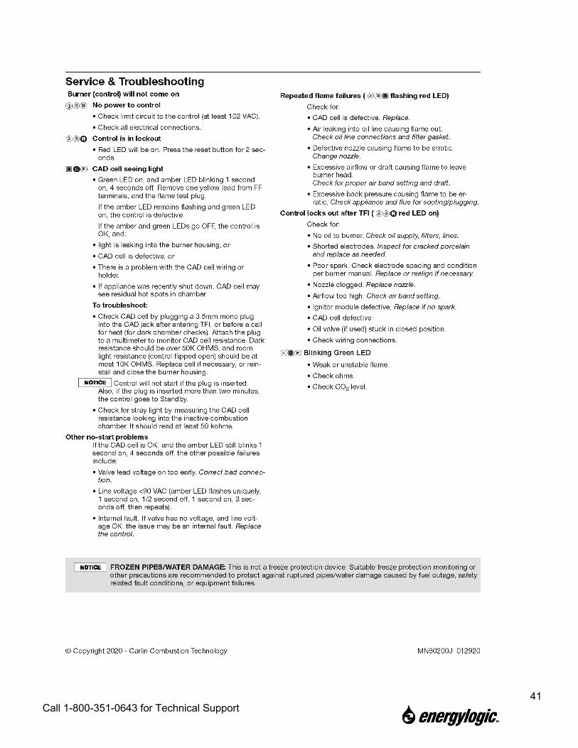
8.2 Primary Control Instructions

39 Call 1-800-351-0643 for Technical Support
Not used with RES 75 kBTU/h units

40 Call 1-800-351-0643 for Technical Support
No latch up with RES 75 kBTU/h units
41 Call 1-800-351-0643 for Technical Support

42 Call 1-800-351-0643 for Technical Support
8.3 Chimney Flue Installation Instructions
Flue Installation Instructions (Kit #: 81010010 - Thru the Roof, Rubber Boot) These instructions describe how to install the flue kit directed vertically from the heater outlet directly through the roof (up to 16’ from floor) and supported on the exterior by the roof. If your installation situation differs (such as flue passing through ceiling or attic space, non-vertical segments, or interior support required) please contact Technical Support for additional parts and installation instructions. Refer to the diagram on page 4 for the parts supplied. Please read and understand the Installation and Operation Manual that was provided with your heater completely before attempting to install or operate your equipment. WARNING: Flue installation should only be attempted by qualified personnel. Use appropriate equipment and safety measures when working at heights. If you need to run your flue through the wall, rather than through the roof as shown in these instructions, a thru-the-wall flue kit will be required. If you did not purchase one, please contact technical support to order the additional parts needed. INSIDE 1. Locate the heater on the floor and ensure a minimum clearance of 6
inches between the back of the heater cabinet and the wall. Ensure there is a clear path from the exhaust outlet on top of the heater to the roof. NOTE that there must be 18 inches of clearance between single wall (black pipe) and anything combustible, and 2 inches of clearance between double-wall pipe and anything combustible.
OUTSIDE (ON ROOF)
2. Confirm that there are no obstructions in the area where the flue will exit the building. Ensure there are no vents or air intakes near the flue exit location that could draw exhaust into the building. NOTE that the flue must extend 2 feet higher than anything within 10 feet of it.
INSIDE 3. Using a plumb line, locate the point on roof directly vertical from the exhaust outlet on the heater. Drill a pilot
hole through roof. If the roof has ridges, try to center on a ridge or between two ridges.

43 Call 1-800-351-0643 for Technical Support
4. Move or cover the heater and any other equipment that might be damaged by falling debris when the hole in the roof is cut.
5. Cut back the roof insulation to allow at least 2 inchs of clearance around the double-wall pipe. Due to the slope of the roof, the cut will be an oval, rather than just a circle. Use the 2” Clearance column in the table below to determine the proper dimensions of the oval. NOTE: The roof slope is measured in inches of vertical rise per foot of horizontal run (i.e., “0-12” is a flat roof and “12-12” is a roof with a 45 degree slope).
Width x Height of Oval
to Cut Roof Slope 10 x 12 x
0-12 10.0 12.0 1-12 10.5 12.0 2-12 10.5 12.5 3-12 10.5 12.5 4-12 10.5 13.0 5-12 11.0 13.0 6-12 11.0 13.5 7-12 12.0 14.0 8-12 12.0 14.5 9-12 12.5 15.0 10-12 13.0 16.0 11-12 13.5 16.5 12-12 14.5 17.0
Applies 6" DW Flue 1" Clearance
6" DW Flue; 2" Clearance
OUTSIDE (ON ROOF)
6. Locate pilot hole in roof and cut an oval hole around it (refer to chart above for hole sizing on sloped roof). NOTE: For a metal roof, use the 1” Clearance column. For a combustible roof, use the 2” Clearance column.
7. Loosely assemble Roof Mount Bracket per the instructions included with it. Slide the 3-foot long, double-wall pipe through band on bracket, so band is 12 inches from male end of pipe, with “L” brackets towards female end. Tighten band so pipe is locked in place. Leave nuts for the “L” brackets a little loose, so the angle can be adjusted. [NOTE: The backet can also be flipped and mounted to structure underneath the roof from the inside.]
8. Insert the female end of the pipe through the hole in the roof and lower it down so the bracket rests on the roof. 9. Align the bracket over the hole, with the “L” brackets running up/down the roof, and secure it to the roof with
the provided self-drilling screws, or with appropriate fasteners for the roof material. 10. Install the 2-foot long, double-walled pipe onto the 3-foot long pipe. Twist to lock into place. 11. Use a level to ensure the pipe is vertical and tighten the nuts on the “L” brackets to lock the angle.

44 Call 1-800-351-0643 for Technical Support
12. Trim rubber boot to correct size according to markings on boot and double-wall pipe size. NOTE: 6-inch double-wall pipe has an outer diameter of 8 inches.
13. Slide boot over pipe and down onto roof. 14. Liberally apply sealant under base perimeter of boot. Form boot to roof
surface and screw metal-lined edge to roof using remaining self-drilling screws evenly spaced (or appropriate fasteners for roof material.)
15. Apply sealant all the way around the top of boot. 16. NOTE: Top of piping must be at least 3 feet higher than roof where exited and at least 2 feet higher than any
portion of roof within 10 feet. Additional pipe sections may be purchased to extend the pipe higher if required. If going over 5 feet above roof, as extended roof support should be added (part # 4913).
17. Install rain cap to top of pipe. Twist to lock in place.
INSIDE 18. Relocate or uncover heater. Install tee and draft control, crimped side down, into exhaust outlet on top. 19. Install crimped to black pipe adapter into tee. 20. Install single-wall black pipe up to near the end of the double-wall pipe. NOTE: Single-wall pipe must have a
minimum clearance of 18 inches from any combustible materials. Also, single-wall flue piping should never be used on the exterior of building.
21. Install slip connector into last piece of black pipe. 22. Slide firestop plate over double-wall pipe and against roof. Secure in place with sheet metal screws into double
wall pipe. 23. Install finishing collar into end of double-wall pipe, twist to lock in place. 24. Slide slip connector up and secure to the finishing collar with three sheet metal screws. 25. Ensure piping is vertically level and secure tee, adapter and black piping at each joint with at least three sheet
metal screws.
Rubber

45 Call 1-800-351-0643 for Technical Support
4918 - Black Pipe, SW - 6" x 24"
70017 - Rubber Boot - Dektite #8
76001403 - Firestop Shield
4920 - Slip Connector - 6" x 14"
74000270 - Roof Support Bracket
76001406 - Tee and Damper, 6", Black
4804 - Chimney Pipe, DW - 6" x 36"
76001405 - Adapter, 6" Crimped to Black Pipe
4909 - Chimney Cap
4912 - Finishing Collar (SW to DW Adapter)
4803 - Chimney Pipe, DW - 6" x 24"

46 Call 1-800-351-0643 for Technical Support
8.4 Heater Specifications
Multi-Fuel Burning Appliance
Model Number 75H
Bonnet Capacity Output 58,922 BTU/Hour
Fuel Input 0.54 GPH
Nozzle Only 30609-11
Approved Fuels ASTM D396 No. 2 Fuel Oil, Used Crankcase Oil, and Used Automatic Transmission Fluid
Designed Outlet Air Temperature 250°F Maximum
Tank Capacity 10 Gallons (Approx. 7 Usable)
Flue Draft -0.04" WC (Minimum 10’ Stack) Atomizing Air Pressure 3-4 PSI
Fan Size 13"
Flue Size 6”
Unit Heater No Ductwork
Fuse Size 8A (15A Max)
Burner Motor 1/7 HP, 115V/60Hz, 3450 RPM, 1.5A
Metering Pump Motor 15Watt, 115V/60Hz, 0.3A
Ignition Transformer & Control Circuit 115V/60Hz, 1.0A
Oil Preheaters 115V/60Hz, 3.0A Maximum Heater Weight (Tank Empty) 210 lbs
Heater Dimensions 75”H x 21”W x 26”L
Minimum Clearance to Combustible Surfaces
Top - 18" Front - 24" Sides - 18" Rear - 6"
Flue Pipe - 18"
For commercial and industrial use only.
The heater should not be used in buildings where explosive vapors may be present.
The heater should be mounted to non-combustible flooring.

8.5 75H Heater Maintenance Schedule and Log Location:
Have this record available when calling for support. Unit ID:
Service Schedule Initial and Date of Service:
Clean ash from heat exchanger, flue, damper, and draft gauge probe
Every 1,000 hours of operation
or Annually
Remove and clean in-tank fill strainer As needed.
Drain fluid (water) from bottom of tank Check monthly, drain as necessary.
Remove and clean in-tank fuel pickup strainer
As needed - indicated by vacuum gauge.
Clean fuel tank As needed or required by code.
Clean fan Annually Clean nozzle line assembly Annually Check retention head & electrode settings Annually Clean solenoid valve Annually Check air compressor pressure performance, replace filter. Annually Clean cad cell lens Annually Check/replace burner gasket Annually Test fire furnace after maintenance and check for proper burner adjustment After Annual Maintenance
Gauge Readings (After Maintenance)
Pump Vacuum Reading: Pump Pressure Reading:
Draft Gauge Reading: Hour Meter Reading:
Service Company:_______________________________ Contact: ___________________________ Address: ______________________________________ Phone: ____________________________ * This schedule is the minimum recommended. If you see smoke or have trip-outs then the unit must be shut down and serviced immediately. Increase the maintenance as your situation requires.
48 Call 1-800-351-0643 for Technical Support
8.6 Limited Warranty
EnergyLogic, LLC, MANUFACTURER, warrants to the buyer that MANUFACTURER’s heater be free from defect in material and workmanship according to the provisions and limitations set forth herein for a period of one (1) year from the Effective Date (as defined below) or 1,500 hours of operation, whichever occurs first. The buyer is responsible for registering the unit with the MANUFACTURER. If the unit is not registered, the buyer is responsible for maintaining proof of the purchase date of the unit. The warranty coverage period begins on the date (the “Effective Date”) of purchase, as established by the buyer, or otherwise on the date of manufacture as indicated by the serial number. No warranty claim examination shall commence until the unit is registered with the MANUFACTURER.
Non-consumables or parts that are not associated with a maintenance service interval because of normal wear shall be warranted for a period of one (1) years from the Effective Date or 1,500 hours of operation, whichever occurs first. A second year will be activated when the product is registered with the Manufacturer with in the first 30 days of receipt of the Product.
Parts replaced during the original equipment warranty period as detailed herein shall carry either a one (1) year warranty from the date of purchase or the remainder of the factory warranty for the original equipment, whichever occurs last. In no event shall a part replaced under the original warranty carry a warranty that extends beyond one year from the expiration of the original factory warranty period.
Warranty Exclusions:
1. Consumable parts or any part that is associated with a normal maintenance interval because of normal wear and tear (filters, seals, gaskets, air
compressor vanes, batteries, insulation, heater cabinets). 2. Products or parts which are not maintained in accordance with the service frequency and methods described in the MANUFACTURER’S instructions
furnished and / or available upon request from the buyer. 3. Parts and products that are not installed and operated according to MANUFACTURER’S instructions furnished and / or available upon request from
the buyer. 4. Repairs made with parts or accessories which are not genuine EnergyLogic LLC or EnergyLogic LLC approved 5. Installations not in accordance with Manufacturers Installation Manual, UL, NFPA guidelines, federal, state, and local codes and regulations. 6. Labor or other costs incurred in troubleshooting, repair, removal, transportation, installation, service or handling of parts. 7. Claims, representation, or warranty made by any dealer, distributor, or other person that is inconsistent with or is more expansive than the provisions
provided herein. 8. Parts that are altered from original specifications of the MANUFACTURER or are damaged because of misuse, improper handling, storage, or use in
conjunction with other parts not authorized by MANUFACTURER. 9. Products that have been moved from the original installation site or that have been sold or exchanged to a person other than the original buyer. 10. Equipment or products installed outside of the continental U.S. or Canada. 11. Products or parts in which the serial number has been altered, defaced, or removed.
The buyer must assist the MANUFACTURER’S Technical Support group during over-the-phone problem diagnosis in order to help substantiate a warranty condition. A course of action will be determined by the MANUFACTURER if repair or replacement is deemed necessary.
MANUFACTURER’S liability under this warranty shall be limited to the repair or replacement of any part or parts that may prove to be defective under such normal operation and use, subject to MANUFACTURER’S examination and determination to its satisfaction that such part or parts are so defective.
Obtaining Warranty Service:
If the local Service Provider is unknown, contact EnergyLogic, LLC at 4109 Capital Circle, Janesville, WI 53546, or at 1-615-471-5290. A representative will assist you in locating the nearest authorized service provider or in verifying the warranty coverage. The Unit Registration identification number will be required. Please refer to our website at www.energylogic.com for more information.
In order for a warranty claim to be acknowledged by the MANUFACTURER, the buyer must be issued a Return Authorization (RA) number and the product must be Warranty Registered. After obtaining an RA number, the buyer must properly package the part to avoid damage during shipment with the RA number visible on the outside of the box. A credit card number must be provided in order for the replacement part to be shipped and the part must be returned within 30 days of receipt of the replacement part in order to avoid charges.
If MANUFACTURER determines that a problem with a product or part is not covered under the Limited Warranty, the buyer will be notified and informed of service alternatives available on a fee basis.
DISCLAIMER AND LIMITATION OF DAMAGES: THIS LIMITED WARRANTY IS EXPRESSLY IN LIEU OF ALL OTHER WARRANTIES, EXPRESSED OR IMPLIED, TO THE EXCLUSION OF ANY AND ALL OTHER WARRANTIES OR REPRESENTATIONS THAT MAY BE EXPRESSED OR IMPLIED BY ANY LITERATURE, PACKAGING, SAMPLES, MODELS, DATA OR PERSONS. MANUFACTURER DOES NOT ASSUME, NOR DO WE AUTHORIZE ANY EMPLOYEE, AGENT, OR OTHER PERSON TO ASSUME FOR US, ANY OTHER RESPONSIBILITY OR LIABILITY IN CONNECTION WITH THE SALE OF THE GOODS COVERED HEREBY. MANUFACTURER HEREBY DISCLAIMS ANY WARRANTY OF MERCHANTABILITY OR FITNESS FOR A PARTICULAR PURPOSE OR USE. MANUFACTURER’S MAXIMUM LIABILITY HEREUNDER SHALL NEVER EXCEED THE COST OF THE PRODUCT. MANUFACTURER IS NOT RESPONSIBLE FOR OR LIABLE FOR DIRECT, INDIRECT, SPECIAL, INCIDENTAL, CONSEQUENTIAL OR PUNITIVE DAMAGES RESULTING FROM THE USE OF THE GOODS COVERED HEREBY OR ANY BREACH OF WARRANTY OR UNDER ANY OTHER LEGAL THEORY, INCLUDING BUT NOT LIMITED TO CONTRACT, TORT, NEGLIGENCE, STRICT LIABILITY, LOST PROFITS OR GOODWILL, LOSS OF TIME, INCONVENIENCE, LOST FUEL, LOST SAVINGS, LABOR CHARGES OR OTHER INCIDENTAL OR CONSEQUENTIAL DAMAGES WITH RESPECT TO PERSONS, BUSINESS OR PROPERTY WHETHER AS A RESULT OF BREACH OF WARRANTY OR OTHERWISE. THIS WARRANTY IS LIMITED TO THE PRECISE TERMS SET FORTH ABOVE, AND PROVIDES EXCLUSIVE REMEDIES EXPRESSLY IN LIEU OF ALL OTHER REMEDIES.