installation and administration guide - … services installation and administration guide, ......
TRANSCRIPT
H Y P E R I O N ® P R O V I D E R S E R V I C E S
R E L E A S E 9 . 3 . 1 . 1 . 0
I N S T A L L A T I O N A N D A D M I N I S T R A T I O NG U I D E

Provider Services Installation and Administration Guide, 9.3.1.1.0
Copyright © 2005, 2008, Oracle and/or its affiliates. All rights reserved.
Authors: Information Development Team
The Programs (which include both the software and documentation) contain proprietary information; they are providedunder a license agreement containing restrictions on use and disclosure and are also protected by copyright, patent, andother intellectual and industrial property laws. Reverse engineering, disassembly, or decompilation of the Programs, exceptto the extent required to obtain interoperability with other independently created software or as specified by law, isprohibited.
The information contained in this document is subject to change without notice. If you find any problems in thedocumentation, please report them to us in writing. This document is not warranted to be error-free. Except as may beexpressly permitted in your license agreement for these Programs, no part of these Programs may be reproduced ortransmitted in any form or by any means, electronic or mechanical, for any purpose.
If the Programs are delivered to the United States Government or anyone licensing or using the Programs on behalf of theUnited States Government, the following notice is applicable:
U.S. GOVERNMENT RIGHTS Programs, software, databases, and related documentation and technical data delivered toU.S. Government customers are "commercial computer software" or "commercial technical data" pursuant to theapplicable Federal Acquisition Regulation and agency-specific supplemental regulations. As such, use, duplication,disclosure, modification, and adaptation of the Programs, including documentation and technical data, shall be subjectto the licensing restrictions set forth in the applicable Oracle license agreement, and, to the extent applicable, the additionalrights set forth in FAR 52.227-19, Commercial Computer Software--Restricted Rights (June 1987). Oracle USA, Inc., 500Oracle Parkway, Redwood City, CA 94065.
The Programs are not intended for use in any nuclear, aviation, mass transit, medical, or other inherently dangerousapplications. It shall be the licensee's responsibility to take all appropriate fail-safe, backup, redundancy and other measuresto ensure the safe use of such applications if the Programs are used for such purposes, and we disclaim liability for anydamages caused by such use of the Programs.
Oracle is a registered trademark of Oracle Corporation and/or its affiliates. Other names may be trademarks of theirrespective owners.
The Programs may provide links to Web sites and access to content, products, and services from third parties. Oracle isnot responsible for the availability of, or any content provided on, third-party Web sites. You bear all risks associated withthe use of such content. If you choose to purchase any products or services from a third party, the relationship is directlybetween you and the third party. Oracle is not responsible for: (a) the quality of third-party products or services; or (b)fulfilling any of the terms of the agreement with the third party, including delivery of products or services and warrantyobligations related to purchased products or services. Oracle is not responsible for any loss or damage of any sort that youmay incur from dealing with any third party.

Contents
Chapter 1. Provider Services Overview . . . . . . . . . . . . . . . . . . . . . . . . . . . . . . . . . . . . . . . . . . . . . . . . . . . . . 9
Provider Services Introduction . . . . . . . . . . . . . . . . . . . . . . . . . . . . . . . . . . . . . . . . . . . . 9
Key Features . . . . . . . . . . . . . . . . . . . . . . . . . . . . . . . . . . . . . . . . . . . . . . . . . . . . . . 10
Components . . . . . . . . . . . . . . . . . . . . . . . . . . . . . . . . . . . . . . . . . . . . . . . . . . . . . . . . . 11
Java API . . . . . . . . . . . . . . . . . . . . . . . . . . . . . . . . . . . . . . . . . . . . . . . . . . . . . . . . . . . . 11
Smart View . . . . . . . . . . . . . . . . . . . . . . . . . . . . . . . . . . . . . . . . . . . . . . . . . . . . . . . . . . 12
XML for Analysis . . . . . . . . . . . . . . . . . . . . . . . . . . . . . . . . . . . . . . . . . . . . . . . . . . . . . 13
Apache Tomcat . . . . . . . . . . . . . . . . . . . . . . . . . . . . . . . . . . . . . . . . . . . . . . . . . . . . . . 14
Hyperion . . . . . . . . . . . . . . . . . . . . . . . . . . . . . . . . . . . . . . . . . . . . . . . . . . . . . . . . . . . 14
Shared Services . . . . . . . . . . . . . . . . . . . . . . . . . . . . . . . . . . . . . . . . . . . . . . . . . . . . . . . 15
Deployment Options . . . . . . . . . . . . . . . . . . . . . . . . . . . . . . . . . . . . . . . . . . . . . . . . . . . 15
Deployment Scenarios . . . . . . . . . . . . . . . . . . . . . . . . . . . . . . . . . . . . . . . . . . . . . . . 15
Deployment and Configuration Guidelines . . . . . . . . . . . . . . . . . . . . . . . . . . . . . . . . 16
Chapter 2. Installing Provider Services . . . . . . . . . . . . . . . . . . . . . . . . . . . . . . . . . . . . . . . . . . . . . . . . . . . 19
Prerequisites . . . . . . . . . . . . . . . . . . . . . . . . . . . . . . . . . . . . . . . . . . . . . . . . . . . . . . . . . 19
Hyperion License Compliance . . . . . . . . . . . . . . . . . . . . . . . . . . . . . . . . . . . . . . . . . . . . 20
Launching the Installers . . . . . . . . . . . . . . . . . . . . . . . . . . . . . . . . . . . . . . . . . . . . . . . . 20
Launching Installers on UNIX . . . . . . . . . . . . . . . . . . . . . . . . . . . . . . . . . . . . . . . . . 20
Installing Provider Services . . . . . . . . . . . . . . . . . . . . . . . . . . . . . . . . . . . . . . . . . . . . . . 21
Provider Services and Previous Installations . . . . . . . . . . . . . . . . . . . . . . . . . . . . . . . 22
Installing the Smart View Client . . . . . . . . . . . . . . . . . . . . . . . . . . . . . . . . . . . . . . . . . . . 22
What Happens During Installation . . . . . . . . . . . . . . . . . . . . . . . . . . . . . . . . . . . . . . . . 23
Files Installed in the Provider Directory . . . . . . . . . . . . . . . . . . . . . . . . . . . . . . . . . . 24
Documentation Installed . . . . . . . . . . . . . . . . . . . . . . . . . . . . . . . . . . . . . . . . . . . . . 24
About Hyperion Home . . . . . . . . . . . . . . . . . . . . . . . . . . . . . . . . . . . . . . . . . . . . . . . . . 25
Hyperion Home Location . . . . . . . . . . . . . . . . . . . . . . . . . . . . . . . . . . . . . . . . . . . . 25
Files Installed in the HYPERION_HOME Directory . . . . . . . . . . . . . . . . . . . . . . . . . 26
Changing the Hyperion Home Location . . . . . . . . . . . . . . . . . . . . . . . . . . . . . . . . . . 27
Selecting the ESSLANG Value . . . . . . . . . . . . . . . . . . . . . . . . . . . . . . . . . . . . . . . . . . . . 28
Contents iii

Chapter 3. Configuring Provider Services . . . . . . . . . . . . . . . . . . . . . . . . . . . . . . . . . . . . . . . . . . . . . . . . . 29
Hyperion Configuration Utility . . . . . . . . . . . . . . . . . . . . . . . . . . . . . . . . . . . . . . . . . . . 29
Task Sequence . . . . . . . . . . . . . . . . . . . . . . . . . . . . . . . . . . . . . . . . . . . . . . . . . . . . 30
Restricted Characters . . . . . . . . . . . . . . . . . . . . . . . . . . . . . . . . . . . . . . . . . . . . . . . 30
Troubleshooting . . . . . . . . . . . . . . . . . . . . . . . . . . . . . . . . . . . . . . . . . . . . . . . . . . 30
Satisfying Initial Requirements . . . . . . . . . . . . . . . . . . . . . . . . . . . . . . . . . . . . . . . . . . . 30
Before You Run Hyperion Configuration Utility . . . . . . . . . . . . . . . . . . . . . . . . . . . . . . . 30
Configuring Product Upgrades . . . . . . . . . . . . . . . . . . . . . . . . . . . . . . . . . . . . . . . . . . . 31
Configuring Provider Services . . . . . . . . . . . . . . . . . . . . . . . . . . . . . . . . . . . . . . . . . . . . . 31
Registering With Shared Services . . . . . . . . . . . . . . . . . . . . . . . . . . . . . . . . . . . . . . . 33
Deploying to the Application Server . . . . . . . . . . . . . . . . . . . . . . . . . . . . . . . . . . . . 35
What Happens During Deployment . . . . . . . . . . . . . . . . . . . . . . . . . . . . . . . . . . . . 36
Integrating Provider Services with SiteMinder . . . . . . . . . . . . . . . . . . . . . . . . . . . . . . . . 37
Reconfiguring Products . . . . . . . . . . . . . . . . . . . . . . . . . . . . . . . . . . . . . . . . . . . . . . . . 37
Chapter 4. Starting Shared Services and Provider Services . . . . . . . . . . . . . . . . . . . . . . . . . . . . . . . . . . . . . 39
Verifying Startup Dependencies . . . . . . . . . . . . . . . . . . . . . . . . . . . . . . . . . . . . . . . . . . . 39
Starting and Stopping Shared Services . . . . . . . . . . . . . . . . . . . . . . . . . . . . . . . . . . . . . . 39
Starting Shared Services . . . . . . . . . . . . . . . . . . . . . . . . . . . . . . . . . . . . . . . . . . . . . . 39
Verifying Successful Startup of Shared Services . . . . . . . . . . . . . . . . . . . . . . . . . . . . . 41
Stopping Shared Services . . . . . . . . . . . . . . . . . . . . . . . . . . . . . . . . . . . . . . . . . . . . . 42
Testing the Provider Services Installation . . . . . . . . . . . . . . . . . . . . . . . . . . . . . . . . . 43
Starting Provider Services . . . . . . . . . . . . . . . . . . . . . . . . . . . . . . . . . . . . . . . . . . . . 45
Stopping Provider Services . . . . . . . . . . . . . . . . . . . . . . . . . . . . . . . . . . . . . . . . . . . 46
Chapter 5. Uninstalling Provider Services and Smart View . . . . . . . . . . . . . . . . . . . . . . . . . . . . . . . . . . . . . . 47
Uninstalling Provider Services . . . . . . . . . . . . . . . . . . . . . . . . . . . . . . . . . . . . . . . . . . . . 47
Uninstalling the Smart View Client . . . . . . . . . . . . . . . . . . . . . . . . . . . . . . . . . . . . . . . . 47
Chapter 6. Upgrading Provider Services and Smart View . . . . . . . . . . . . . . . . . . . . . . . . . . . . . . . . . . . . . . . 49
Upgrading Provider Services . . . . . . . . . . . . . . . . . . . . . . . . . . . . . . . . . . . . . . . . . . . . . 49
Upgrading Smart View Client . . . . . . . . . . . . . . . . . . . . . . . . . . . . . . . . . . . . . . . . . . . . 50
Chapter 7. Shared Services User Management . . . . . . . . . . . . . . . . . . . . . . . . . . . . . . . . . . . . . . . . . . . . . 53
About Shared Services User Management . . . . . . . . . . . . . . . . . . . . . . . . . . . . . . . . . . . . 53
Prerequisites . . . . . . . . . . . . . . . . . . . . . . . . . . . . . . . . . . . . . . . . . . . . . . . . . . . . . . 53
Compatibility Matrix . . . . . . . . . . . . . . . . . . . . . . . . . . . . . . . . . . . . . . . . . . . . . . . 54
Chapter 8. Administering Provider Services . . . . . . . . . . . . . . . . . . . . . . . . . . . . . . . . . . . . . . . . . . . . . . . . 55
Administering Provider Services . . . . . . . . . . . . . . . . . . . . . . . . . . . . . . . . . . . . . . . . . . 55
Adding Provider Services . . . . . . . . . . . . . . . . . . . . . . . . . . . . . . . . . . . . . . . . . . . . . 56
iv Contents

Editing the Authenticating Essbase Server . . . . . . . . . . . . . . . . . . . . . . . . . . . . . . . . . 56
Removing Provider Services . . . . . . . . . . . . . . . . . . . . . . . . . . . . . . . . . . . . . . . . . . 56
Connecting to a Stand-alone Essbase Server . . . . . . . . . . . . . . . . . . . . . . . . . . . . . . . 57
Removing a Stand-alone Server . . . . . . . . . . . . . . . . . . . . . . . . . . . . . . . . . . . . . . . . 58
Connecting to a Cluster of Essbase Servers . . . . . . . . . . . . . . . . . . . . . . . . . . . . . . . . 58
Connecting to Provider Services . . . . . . . . . . . . . . . . . . . . . . . . . . . . . . . . . . . . . . . . 61
Specifying Logging Properties . . . . . . . . . . . . . . . . . . . . . . . . . . . . . . . . . . . . . . . . . 62
Monitoring Sessions . . . . . . . . . . . . . . . . . . . . . . . . . . . . . . . . . . . . . . . . . . . . . . . . 62
Specifying Session Timeout . . . . . . . . . . . . . . . . . . . . . . . . . . . . . . . . . . . . . . . . . . . 63
Specifying Maximum Rows and Columns . . . . . . . . . . . . . . . . . . . . . . . . . . . . . . . . . 63
Automatically Deploying Client Upgrades . . . . . . . . . . . . . . . . . . . . . . . . . . . . . . . . 64
Configuration Options in essbase.properties . . . . . . . . . . . . . . . . . . . . . . . . . . . . . . . . . . 65
Configuring essbase.properties . . . . . . . . . . . . . . . . . . . . . . . . . . . . . . . . . . . . . . . . 65
olap.server.netConnectRetry . . . . . . . . . . . . . . . . . . . . . . . . . . . . . . . . . . . . . . . . . . 65
olap.server.netDelay . . . . . . . . . . . . . . . . . . . . . . . . . . . . . . . . . . . . . . . . . . . . . . . . 66
olap.server.netRetryCount . . . . . . . . . . . . . . . . . . . . . . . . . . . . . . . . . . . . . . . . . . . . 66
olap.server.netSocketTimeOut . . . . . . . . . . . . . . . . . . . . . . . . . . . . . . . . . . . . . . . . . 67
Analytic Server Clustering Concepts . . . . . . . . . . . . . . . . . . . . . . . . . . . . . . . . . . . . . . . . 67
Clustering Examples . . . . . . . . . . . . . . . . . . . . . . . . . . . . . . . . . . . . . . . . . . . . . . . . 68
Fault Tolerance . . . . . . . . . . . . . . . . . . . . . . . . . . . . . . . . . . . . . . . . . . . . . . . . . . . . . . . 72
Implementation . . . . . . . . . . . . . . . . . . . . . . . . . . . . . . . . . . . . . . . . . . . . . . . . . . . 72
Disabling and Enabling Components Using Java APIs . . . . . . . . . . . . . . . . . . . . . . . . 72
Chapter 9. Clustering Provider Services . . . . . . . . . . . . . . . . . . . . . . . . . . . . . . . . . . . . . . . . . . . . . . . . . . 75
Provider Services Clustering . . . . . . . . . . . . . . . . . . . . . . . . . . . . . . . . . . . . . . . . . . . . . 75
Clustering on Tomcat . . . . . . . . . . . . . . . . . . . . . . . . . . . . . . . . . . . . . . . . . . . . . . . . . . 78
Clustering on WebLogic 8.1.6 . . . . . . . . . . . . . . . . . . . . . . . . . . . . . . . . . . . . . . . . . . . . 81
Configuring the WebLogic Load Balancing Plug-in . . . . . . . . . . . . . . . . . . . . . . . . . . 85
Clustering on WebLogic 9.1 . . . . . . . . . . . . . . . . . . . . . . . . . . . . . . . . . . . . . . . . . . . . . . 86
Clustering on WebSphere 6.0.2.11 and 6.1.0.5 . . . . . . . . . . . . . . . . . . . . . . . . . . . . . . . . . 92
Vertical Clustering Setup Sequence . . . . . . . . . . . . . . . . . . . . . . . . . . . . . . . . . . . . . 92
Prerequisites . . . . . . . . . . . . . . . . . . . . . . . . . . . . . . . . . . . . . . . . . . . . . . . . . . . . . . 92
Clustering Setup . . . . . . . . . . . . . . . . . . . . . . . . . . . . . . . . . . . . . . . . . . . . . . . . . . . 92
Clustering on Oracle 10g Application Server . . . . . . . . . . . . . . . . . . . . . . . . . . . . . . . . . 102
Chapter 10. Configuring Provider Services in SSL Mode . . . . . . . . . . . . . . . . . . . . . . . . . . . . . . . . . . . . . . 105
Before You Begin . . . . . . . . . . . . . . . . . . . . . . . . . . . . . . . . . . . . . . . . . . . . . . . . . . . . 105
Configuring SSL on Tomcat . . . . . . . . . . . . . . . . . . . . . . . . . . . . . . . . . . . . . . . . . . . . 105
Configuring SSL on WebLogic 8.1.6 . . . . . . . . . . . . . . . . . . . . . . . . . . . . . . . . . . . . . . . 107
Configuring a Simple SSL Setup on WebLogic . . . . . . . . . . . . . . . . . . . . . . . . . . . . 108
Contents v

Configuring a Custom SSL Setup on WebLogic . . . . . . . . . . . . . . . . . . . . . . . . . . . . 108
Configuring SSL on WebLogic 9.1 . . . . . . . . . . . . . . . . . . . . . . . . . . . . . . . . . . . . . . . . 109
Configuring a Simple SSL Setup on WebLogic . . . . . . . . . . . . . . . . . . . . . . . . . . . . 110
Configuring a Custom SSL Setup on WebLogic . . . . . . . . . . . . . . . . . . . . . . . . . . . . 110
Configuring SSL on WebSphere 6.0.2.11 and 6.1.0.5 . . . . . . . . . . . . . . . . . . . . . . . . . . . 112
Using the Default SSL Configuration . . . . . . . . . . . . . . . . . . . . . . . . . . . . . . . . . . . 112
Using a Custom SSL Configuration . . . . . . . . . . . . . . . . . . . . . . . . . . . . . . . . . . . . 112
Configuring SSL When WebSphere is Manually Deployed . . . . . . . . . . . . . . . . . . . . 114
Configuring SSL on Oracle 10g . . . . . . . . . . . . . . . . . . . . . . . . . . . . . . . . . . . . . . . . . . 115
Chapter 11. Working with XMLA . . . . . . . . . . . . . . . . . . . . . . . . . . . . . . . . . . . . . . . . . . . . . . . . . . . . . . . 117
Key Features . . . . . . . . . . . . . . . . . . . . . . . . . . . . . . . . . . . . . . . . . . . . . . . . . . . . . . . . 117
Methods . . . . . . . . . . . . . . . . . . . . . . . . . . . . . . . . . . . . . . . . . . . . . . . . . . . . . . . . . . . 117
Discover . . . . . . . . . . . . . . . . . . . . . . . . . . . . . . . . . . . . . . . . . . . . . . . . . . . . . . . . 118
Execute . . . . . . . . . . . . . . . . . . . . . . . . . . . . . . . . . . . . . . . . . . . . . . . . . . . . . . . . 121
XMLA Rowsets . . . . . . . . . . . . . . . . . . . . . . . . . . . . . . . . . . . . . . . . . . . . . . . . . . . . . . 123
CATALOGS Rowset . . . . . . . . . . . . . . . . . . . . . . . . . . . . . . . . . . . . . . . . . . . . . . . 123
MDSCHEMA_CUBES Rowset . . . . . . . . . . . . . . . . . . . . . . . . . . . . . . . . . . . . . . . . 125
MDSCHEMA_DIMENSIONS Rowset . . . . . . . . . . . . . . . . . . . . . . . . . . . . . . . . . . 127
MDSCHEMA_FUNCTIONS Rowset . . . . . . . . . . . . . . . . . . . . . . . . . . . . . . . . . . . 129
MDSCHEMA_HIERARCHIES Rowset . . . . . . . . . . . . . . . . . . . . . . . . . . . . . . . . . . 131
MDSCHEMA_MEASURES Rowset . . . . . . . . . . . . . . . . . . . . . . . . . . . . . . . . . . . . 134
MDSCHEMA_MEMBERS Rowset . . . . . . . . . . . . . . . . . . . . . . . . . . . . . . . . . . . . . 136
MDSCHEMA_PROPERTIES Rowset . . . . . . . . . . . . . . . . . . . . . . . . . . . . . . . . . . . 139
MDSCHEMA_SETS Rowset . . . . . . . . . . . . . . . . . . . . . . . . . . . . . . . . . . . . . . . . . 143
MDSCHEMA_LEVELS Rowset . . . . . . . . . . . . . . . . . . . . . . . . . . . . . . . . . . . . . . . 143
DISCOVER_SCHEMA_ROWSETS Rowset . . . . . . . . . . . . . . . . . . . . . . . . . . . . . . 146
DISCOVER_DATASOURCES Rowset . . . . . . . . . . . . . . . . . . . . . . . . . . . . . . . . . . 146
DISCOVER_PROPERTIES Rowset . . . . . . . . . . . . . . . . . . . . . . . . . . . . . . . . . . . . 147
DISCOVER_ENUMERATORS Rowset . . . . . . . . . . . . . . . . . . . . . . . . . . . . . . . . . 149
DISCOVER_KEYWORDS Rowset . . . . . . . . . . . . . . . . . . . . . . . . . . . . . . . . . . . . . 150
DISCOVER_LITERALS Rowset . . . . . . . . . . . . . . . . . . . . . . . . . . . . . . . . . . . . . . . 152
Flattened Rowset Examples . . . . . . . . . . . . . . . . . . . . . . . . . . . . . . . . . . . . . . . . . . . . . 152
MDX Examples . . . . . . . . . . . . . . . . . . . . . . . . . . . . . . . . . . . . . . . . . . . . . . . . . . 153
XMLA Examples . . . . . . . . . . . . . . . . . . . . . . . . . . . . . . . . . . . . . . . . . . . . . . . . . . 157
Chapter 12. Working with Java API . . . . . . . . . . . . . . . . . . . . . . . . . . . . . . . . . . . . . . . . . . . . . . . . . . . . . 161
Key Features . . . . . . . . . . . . . . . . . . . . . . . . . . . . . . . . . . . . . . . . . . . . . . . . . . . . . . . . 161
Embedded JAPI . . . . . . . . . . . . . . . . . . . . . . . . . . . . . . . . . . . . . . . . . . . . . . . . . . . . . 161
vi Contents

Chapter 13. Setting Up the Sample Programs . . . . . . . . . . . . . . . . . . . . . . . . . . . . . . . . . . . . . . . . . . . . . 165
Understanding the Sample Programs . . . . . . . . . . . . . . . . . . . . . . . . . . . . . . . . . . . . . . 165
Configuring Provider Servers . . . . . . . . . . . . . . . . . . . . . . . . . . . . . . . . . . . . . . . . . . . . 167
Compiling and Running the Sample Programs . . . . . . . . . . . . . . . . . . . . . . . . . . . . . . . 168
Configuring the Script Files . . . . . . . . . . . . . . . . . . . . . . . . . . . . . . . . . . . . . . . . . . 168
Running the Scripts . . . . . . . . . . . . . . . . . . . . . . . . . . . . . . . . . . . . . . . . . . . . . . . 169
Creating Compile and Run Scripts . . . . . . . . . . . . . . . . . . . . . . . . . . . . . . . . . . . . . 169
Running Compile and Run Scripts . . . . . . . . . . . . . . . . . . . . . . . . . . . . . . . . . . . . . 170
Compatibility with Earlier Versions of Essbase Server . . . . . . . . . . . . . . . . . . . . . . . . . . 170
Appendix A. Manual Deployment of Provider Services on Application Servers . . . . . . . . . . . . . . . . . . . . . . . . 171
Overview . . . . . . . . . . . . . . . . . . . . . . . . . . . . . . . . . . . . . . . . . . . . . . . . . . . . . . . . . . 171
Deployment Options . . . . . . . . . . . . . . . . . . . . . . . . . . . . . . . . . . . . . . . . . . . . . . . 171
Before Deploying . . . . . . . . . . . . . . . . . . . . . . . . . . . . . . . . . . . . . . . . . . . . . . . . . 172
Deploying Provider Services on Application Servers . . . . . . . . . . . . . . . . . . . . . . . . 172
Deploying on Apache Tomcat . . . . . . . . . . . . . . . . . . . . . . . . . . . . . . . . . . . . . . . . . . . 172
Deploying on BEA WebLogic Server 8.1.6 . . . . . . . . . . . . . . . . . . . . . . . . . . . . . . . . . . . 173
Deploying on BEA WebLogic Server 9.1 . . . . . . . . . . . . . . . . . . . . . . . . . . . . . . . . . . . . 175
Deploying on IBM WebSphere Application Server 6.0.2 and 6.1.0.5 . . . . . . . . . . . . . . . . 176
Deploying on Oracle 10g – 10.1.2.0.2 or 10.1.3.1.0 . . . . . . . . . . . . . . . . . . . . . . . . . . . . 178
Creating an OC4J Instance . . . . . . . . . . . . . . . . . . . . . . . . . . . . . . . . . . . . . . . . . . 178
Setting Heap Size . . . . . . . . . . . . . . . . . . . . . . . . . . . . . . . . . . . . . . . . . . . . . . . . . 179
Deploying on Oracle 10g . . . . . . . . . . . . . . . . . . . . . . . . . . . . . . . . . . . . . . . . . . . . 179
Index . . . . . . . . . . . . . . . . . . . . . . . . . . . . . . . . . . . . . . . . . . . . . . . . . . . . . . . . . . . . . 181
Contents vii

viii Contents

1Provider Services Overview
In This Chapter
Provider Services Introduction ... . . . . . . . . . . . . . . . . . . . . . . . . . . . . . . . . . . . . . . . . . . . . . . . . . . . . . . . . . . . . . . . . . . . . . . . . . . . . . . . . . . . . . . . . . . . . . . . . . . 9
Components .. . . . . . . . . . . . . . . . . . . . . . . . . . . . . . . . . . . . . . . . . . . . . . . . . . . . . . . . . . . . . . . . . . . . . . . . . . . . . . . . . . . . . . . . . . . . . . . . . . . . . . . . . . . . . . . . . . . . . . .11
Java API .. . . . . . . . . . . . . . . . . . . . . . . . . . . . . . . . . . . . . . . . . . . . . . . . . . . . . . . . . . . . . . . . . . . . . . . . . . . . . . . . . . . . . . . . . . . . . . . . . . . . . . . . . . . . . . . . . . . . . . . . . . . .11
Smart View... . . . . . . . . . . . . . . . . . . . . . . . . . . . . . . . . . . . . . . . . . . . . . . . . . . . . . . . . . . . . . . . . . . . . . . . . . . . . . . . . . . . . . . . . . . . . . . . . . . . . . . . . . . . . . . . . . . . . . . .12
XML for Analysis.. . . . . . . . . . . . . . . . . . . . . . . . . . . . . . . . . . . . . . . . . . . . . . . . . . . . . . . . . . . . . . . . . . . . . . . . . . . . . . . . . . . . . . . . . . . . . . . . . . . . . . . . . . . . . . . . . . .13
Apache Tomcat.. . . . . . . . . . . . . . . . . . . . . . . . . . . . . . . . . . . . . . . . . . . . . . . . . . . . . . . . . . . . . . . . . . . . . . . . . . . . . . . . . . . . . . . . . . . . . . . . . . . . . . . . . . . . . . . . . . . .14
Hyperion ... . . . . . . . . . . . . . . . . . . . . . . . . . . . . . . . . . . . . . . . . . . . . . . . . . . . . . . . . . . . . . . . . . . . . . . . . . . . . . . . . . . . . . . . . . . . . . . . . . . . . . . . . . . . . . . . . . . . . . . . . .14
Shared Services ... . . . . . . . . . . . . . . . . . . . . . . . . . . . . . . . . . . . . . . . . . . . . . . . . . . . . . . . . . . . . . . . . . . . . . . . . . . . . . . . . . . . . . . . . . . . . . . . . . . . . . . . . . . . . . . . . .15
Deployment Options ... . . . . . . . . . . . . . . . . . . . . . . . . . . . . . . . . . . . . . . . . . . . . . . . . . . . . . . . . . . . . . . . . . . . . . . . . . . . . . . . . . . . . . . . . . . . . . . . . . . . . . . . . . . . .15
Provider Services IntroductionOracle's Hyperion® Provider Services is a middle-tier data-source provider to Oracle'sHyperion® Essbase® – System 9 for Java API, Oracle's Hyperion® Smart View for Office, andXMLA clients. Provider Services supports highly concurrent analytical scenarios and providesscalability and reliability in a distributed Web-enabled enterprise environment.
Figure 1 illustrates the relationship of Provider Services to Java API, Smart View, XMLA, andEssbase.
Provider Services Introduction 9
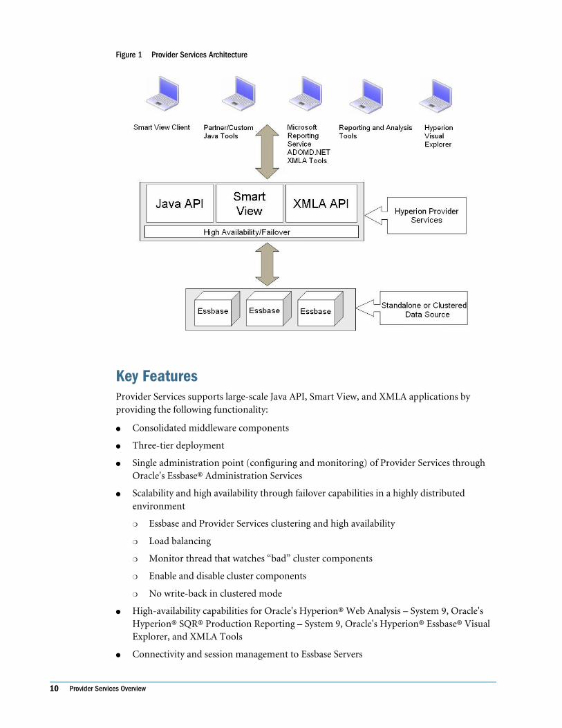
Figure 1 Provider Services Architecture
Key FeaturesProvider Services supports large-scale Java API, Smart View, and XMLA applications byproviding the following functionality:
● Consolidated middleware components
● Three-tier deployment
● Single administration point (configuring and monitoring) of Provider Services throughOracle's Essbase® Administration Services
● Scalability and high availability through failover capabilities in a highly distributedenvironment
❍ Essbase and Provider Services clustering and high availability
❍ Load balancing
❍ Monitor thread that watches “bad” cluster components
❍ Enable and disable cluster components
❍ No write-back in clustered mode
● High-availability capabilities for Oracle's Hyperion® Web Analysis – System 9, Oracle'sHyperion® SQR® Production Reporting – System 9, Oracle's Hyperion® Essbase® VisualExplorer, and XMLA Tools
● Connectivity and session management to Essbase Servers
10 Provider Services Overview

● Alias support for a cluster of Essbase Servers
● Connection timeout to Essbase Servers
● Ease of installation, deployment, and configuration
● Configuration utility for auto-deployment of application servers and registering withOracle's Hyperion® Shared Services
ComponentsThe Provider Services installation comprises:
● Provider Services software
● Java API software
● XMLA interface
● Provider Services uninstall folder, which contains an executable enabling you to uninstallprovider software
● Smart View client installation executable, SmartView.exe or SmartViewHVE.exe (forlicensed Visual Explorer users).
Provider Services is administered through Administration Services. The URL for connecting toProvider Services through Administration Services Console: http://server_name:port/aps/APS.See Essbase Administration Services Online Help for information on usingAdministration Services.
Java APIJava API is available in embedded and three-tier deployments. Both provide a 100% Javaimplementation. With a complete Java solution, platform independence is achieved.
Embedded Java API is provided through .jar files and related property files that a Java API clientcan embed within their application. Java API clients communicate to Essbase through Java API.No installer is required, and no middle-tier server, such as Provider Services, is required to serviceJava API client requests. However, Java API can be embedded in a Java client application in atwo-tier solution or in Hyperion products, such as Offline Planning, for the middle-tierapplication of a three-tier solution. High availability and clustering is not available withembedded Java APIs. You must use Java API with Provider Services to enable high availabilityand clustering.
You can switch from embedded Java API to three-tier mode. Through Java API, Hyperionproducts such as Web Analysis and Production Reporting can use the high-availability featuresof Provider Services. The URL for connecting Provider Services to Java API clients: http://server_name:port/aps/JAPI.
Components 11

You can embed Java API in the middle tier of an application:
Smart ViewSmart View provides a common Microsoft Office add-in for Essbase, Oracle's Hyperion®Financial Management – System 9, Oracle's Hyperion® Planning – System 9, and Oracle's
12 Provider Services Overview

Hyperion® Workspace. You can perform ad hoc analysis, retrieve functions, retrieve data forms,and import Oracle's Hyperion® Reporting and Analysis – System 9 documents. To use SmartView with Essbase, you need Provider Services as a middle-tier server. The URL for connectingProvider Services to Smart View clients is: http://server_name:port/aps/SmartView.
Figure 2 Smart View System Architecture
XML for AnalysisXML for Analysis (XMLA) is an open, industry-standard Web service interface for onlineanalytical processing. The open architecture of XMLA enables development on any language,platform, or operating system. Provider Services provides high availability for XMLA for Essbase.Using Provider Services and XMLA, Microsoft Reporting Services generates and publishesreports for Essbase. The URL for connecting Provider Services to XMLA clients: http://server_name:port/aps/XMLA.
XML for Analysis 13

Figure 3 XMLA System Architecture
Apache TomcatFor your convenience, Hyperion provides Apache Tomcat on the installation media, butHyperion does not own or maintain the Apache Tomcat application server and is not responsiblefor problems encountered with its functionality. Hyperion, however, fully supports the use ofApache Tomcat in its products. In deployments where customers require high availability orfailover, Hyperion recommends a commercially supported application server where thesecapabilities are supported.
Hyperionis part of Reporting and Analysis, a component of Hyperion, a comprehensive BusinessPerformance Management system that integrates modular suites of financial managementapplications with the most comprehensive business intelligence (BI) capabilities for reportingand analysis. The major components of Hyperion:
● Oracle's Hyperion® Foundation Services
● Oracle's Hyperion® Reporting and Analysis – System 9
For an overview, see the Hyperion Installation Start Here.
14 Provider Services Overview
Shared ServicesShared Services enables user provisioning, external authentication definition, metadatasynchronization, data synchronization, and task-flow management for Planning, FinancialManagement, Oracle's Hyperion® Business Modeling, and Oracle's Hyperion® PerformanceScorecard – System 9. You can register Provider Services with Shared Services, but this isnecessary only if you use Shared Services to connect Smart View to Provider Services.
The Hyperion Security Administration Guide describes user-provisioning functionality andexternal authentication. All other Shared Services functionality is described in theadministrator's and user's guides for products that implement Shared Services.
Deployment OptionsYou can install Provider Services on the same computer as Essbase Server or on a differentcomputer, in various configurations. For example, you can install Provider Services on acomputer running Windows and install Essbase Server on a computer running UNIX.
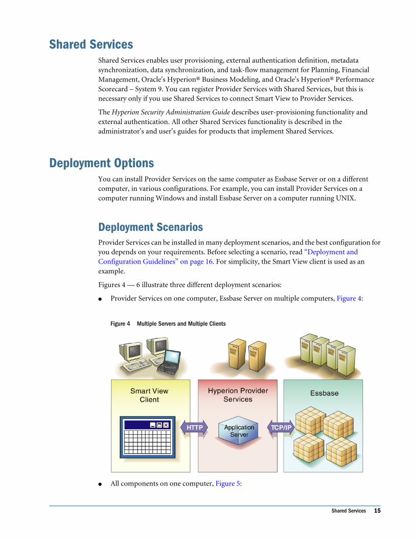
Deployment ScenariosProvider Services can be installed in many deployment scenarios, and the best configuration foryou depends on your requirements. Before selecting a scenario, read “Deployment andConfiguration Guidelines” on page 16. For simplicity, the Smart View client is used as anexample.
Figures 4 — 6 illustrate three different deployment scenarios:
● Provider Services on one computer, Essbase Server on multiple computers, Figure 4:
Figure 4 Multiple Servers and Multiple Clients
● All components on one computer, Figure 5:
Shared Services 15

Figure 5 Single Computer
● Provider Services and Essbase Server on one computer, and Smart View on one or moreclient computers, Figure 6:
Figure 6 Single Server Computer, Multiple Clients
Deployment and Configuration GuidelinesInstall Provider Services and Essbase on the same computer only if the following requirementsexist:
● The computer has the required memory for both components.
16 Provider Services Overview

● If more than 10 users are connected to Provider Services simultaneously, consider (1) usinga computer that employs multiple CPUs for Provider Services, or (2) deploying multipleinstances of Provider Services on multiple computers to improve performance.
Note:
For information on memory requirements for Provider Services and Smart View, see theHyperion Installation Start Here.
Deployment Options 17

18 Provider Services Overview

2Installing Provider Services
In This Chapter
Prerequisites.. . . . . . . . . . . . . . . . . . . . . . . . . . . . . . . . . . . . . . . . . . . . . . . . . . . . . . . . . . . . . . . . . . . . . . . . . . . . . . . . . . . . . . . . . . . . . . . . . . . . . . . . . . . . . . . . . . . . . . .19
Hyperion License Compliance ... . . . . . . . . . . . . . . . . . . . . . . . . . . . . . . . . . . . . . . . . . . . . . . . . . . . . . . . . . . . . . . . . . . . . . . . . . . . . . . . . . . . . . . . . . . . . . . . . .20
Launching the Installers .. . . . . . . . . . . . . . . . . . . . . . . . . . . . . . . . . . . . . . . . . . . . . . . . . . . . . . . . . . . . . . . . . . . . . . . . . . . . . . . . . . . . . . . . . . . . . . . . . . . . . . . . . .20
Installing Provider Services... . . . . . . . . . . . . . . . . . . . . . . . . . . . . . . . . . . . . . . . . . . . . . . . . . . . . . . . . . . . . . . . . . . . . . . . . . . . . . . . . . . . . . . . . . . . . . . . . . . . . .21
Installing the Smart View Client .. . . . . . . . . . . . . . . . . . . . . . . . . . . . . . . . . . . . . . . . . . . . . . . . . . . . . . . . . . . . . . . . . . . . . . . . . . . . . . . . . . . . . . . . . . . . . . . . .22
What Happens During Installation... . . . . . . . . . . . . . . . . . . . . . . . . . . . . . . . . . . . . . . . . . . . . . . . . . . . . . . . . . . . . . . . . . . . . . . . . . . . . . . . . . . . . . . . . . . . . .23
About Hyperion Home ... . . . . . . . . . . . . . . . . . . . . . . . . . . . . . . . . . . . . . . . . . . . . . . . . . . . . . . . . . . . . . . . . . . . . . . . . . . . . . . . . . . . . . . . . . . . . . . . . . . . . . . . . . .25
Selecting the ESSLANG Value ... . . . . . . . . . . . . . . . . . . . . . . . . . . . . . . . . . . . . . . . . . . . . . . . . . . . . . . . . . . . . . . . . . . . . . . . . . . . . . . . . . . . . . . . . . . . . . . . . .28
PrerequisitesBefore installing Provider Services, ensure the following prerequisites are met:
● Ensure that your Analytic Server release is compatible with this release of Provider Services.Refer to the Hyperion Installation Start Here for compatibility information.
● Ensure that your Essbase Server and Administration Services Console release is compatiblewith this release of Provider Services.
● Ensure that your Smart View client release is compatible with this release of ProviderServices.
● On UNIX platforms, if the HYPERION_HOME location is defined from a previous Hyperionproduct installation on the machine to which you are installing, ensure that it is set beforelaunching the Provider Services installer. HYPERION_HOME is where common componentsare installed during some Hyperion product installations. If HYPERION_HOME exists on thecomputer to which you are installing, setting the environment before launching the installerensures that the correct components are installed to the existing location ofHYPERION_HOME. You must install common components to the same location as the existingHYPERION_HOME setting. See “About Hyperion Home” on page 25.
Be aware of existing port usage to resolve port conflicts during installation. See the HyperionInstallation Start Here for more port number information.
Prerequisites 19

Hyperion License ComplianceHyperion no longer ships or requires Oracle's Hyperion® License Server™ (or standalone licensefiles) for use with Hyperion products.
To ensure compliance with your license agreement, Hyperion recommends that you implementan auditing process. In addition, during product configuration with Oracle's Hyperion®Configuration Utility™, you activate only the features you purchased. For more information,see “Hyperion License Compliance” in Hyperion Installation Start Here.
Launching the InstallersBefore installing Provider Services, decide which software installation format to use. You caninstall from files downloaded from the Oracle® E-Delivery site or from a DVD.
➤ To launch the Provider Services installer from the self-extracting download file from the theOracle® E-Delivery site:
1 Log on to the the Oracle® E-Delivery site.
2 Select a language and enter information as requested.
3 Run the appropriate installer.
➤ To launch the Provider Services installer from the DVD:
1 Navigate to the Provider Services directory on the DVD.
2 Navigate to the directory for your platform.
3 Run the installer for your platform:
● setup.exe for Windows
● setup.bin for UNIX
● setup.bin for Linux
Launching Installers on UNIXOn UNIX platforms, you can launch the installer from the console or in XWindows.
➤ To launch the installer in the console, type
./installer file name -console
For example:
./setup.bin -console
➤ To launch the installer in XWindows, type
./installer file name
20 Installing Provider Services

For example:
./setup.bin
Installing Provider ServicesProvider Services provides a cross-platform installer program for Windows and UNIXplatforms.
You access the installer program from the Oracle® E-Delivery site or from a DVD. If you wantto make the installer program available to users wh don't have access, download the program toa network.
Caution!
If you intend to register Provider Services with Shared Services after installation, you may needto save some files from your current Provider Services version before you install the new version.See “Registering With Shared Services ” on page 33 before proceeding with installation.
➤ To install Provider Services:
1 Verify that all prerequisites and system requirements are met.
For detailed information, see the Hyperion Installation Start Here.
2 Download and launch the applicable installer program for the Provider Services software.
See “Launching the Installers” on page 20 for instructions.
3 Follow the installation prompts, keeping in mind the following information:
● You can install Provider Services to any directory except a directory that contains a space inthe directory name (for example, C:\Program Files). The default directory is c:\hyperion.
Note:
You can enter only English alphanumeric characters and these special characters: dash (-),underscore (_), plus sign (+), backslash (\), forward slash (/), dot (.), colon (:). The coloncharacter (:) is supported only for Windows platforms to specify the drive (for example, c:\).
● Hyperion common components are installed to a different directory than the ProviderServices software. Common components are installed to a location called “HyperionHome” (HYPERION_HOME\common for Windows or HYPERION_HOME/common on UNIX).See “About Hyperion Home” on page 25.
● A typical installation installs Provider Services, the common components, and thedocumentation. A custom installation enables you to install Provider Services and thedocumentation separately.
Installing Provider Services 21

● The installer prompts you to select a value for the ESSLANG environment variable. Thedefault value for the ESSLANG variable is English_UnitedStates.Latin1@Binary. Fordetailed information about what you should select for the ESSLANG variable, see “Selectingthe ESSLANG Value” on page 28.
Provider Services and Previous InstallationsIf you have Hyperion System 9 BI+ Analytic High Availability Services or Hyperion System 9 BI+ Analytic Services Smart View Provider installed, you must uninstall them before you installProvider Services. If Provider Services is your current installation, however, you can overinstall(install without uninstalling the previous version).
Overinstalling is not the same as upgrading to a new release; configuration-related information,which is contained in the essbase.properties and domain.db files, is lost as overinstallingoverwrites these two files. To restore the information, you must reconfigure Provider Services.
Installing the Smart View ClientSmart View provides the framework to integrate Microsoft Office products with Essbase, Oracle'sHyperion® Financial Management – System 9, Oracle's Hyperion® Planning – System 9, andOracle's Hyperion® Workspace.
Note:
Because Smart View is an add-in to Microsoft Office products, it can be installed only onMicrosoft Windows.
The installation for Provider Services includes the Smart View installation executable, locatedat Hyperion\AnalyticProviderServices\redist\SmartView.exe orSmartViewHVE.exe (for Visual Explorer licensed users, by default. You can distribute theinstaller to your users by using several methods, for example, by e-mail or by a URL.
After Smart View is installed, users must create a connection to Provider Services in theConnection Manager available from the Hyperion menu in Excel, Word, or PowerPoint.
See the Smart View for Office User's Guide or online help that is installed with Smart View.
Note:
In previous releases of Smart View, the default installation directory was C:\Program Files\HyperionSmartView. Starting with Release 9.0, the default location is C:\Hyperion\SmartView. If you had a pre-9.0 installation of Smart View, you must uninstall Smart Viewbefore installing this release. If you are upgrading from a 9.0 or later release, you can install overthe previous release with this release.
22 Installing Provider Services

➤ To install Smart View:
1 Navigate to the location of the Smart View installation file specified by your administrator.
2 Double-click SmartView.exe or SmartViewHVE.exe.
3 Install Smart View to the default path, C:\Hyperion\SmartView, or click Change to navigate to anotherinstallation location, and click Next.
Note:
You can enter only English alphanumeric characters and these special characters: dash (-),underscore (_), plus sign (+), backslash (\), forward slash (/), dot (.), colon (:). The coloncharacter (:) is supported only for Windows platforms to specify the drive (for example, c:\).
4 Click Install.
5 Click Finish.
The next time Microsoft Excel, Word, or PowerPoint runs, a Hyperion menu is added to themenu bar.
What Happens During InstallationDuring installation, the Provider Services installer program performs the following operations:
● Creates the \AnalyticProviderServices directory and subdirectories under thelocation specified in the installer
● Installs Hyperion common components to the HYPERION_HOME\common directory
Some third-party common components are optional and may not be installed. Forinformation about HYPERION_HOME and for a listing of the directories created, see “AboutHyperion Home” on page 25.
● By default, installs Apache Tomcat application server.
Apache Tomcat is installed to the HYPERION_HOME\common directory. You can change theapplication server for Provider Services using the Configuration Utility.
Note:
Hyperion provides Apache Tomcat on the installation media for convenience if you wantto use it for your deployment. Hyperion does not own or maintain the Apache Tomcatapplication server and is not responsible for problems encountered with its functionality.Hyperion, however, does fully support the use of Apache Tomcat in its products. Indeployments where customers require high availability or failover, Hyperion recommendsto deploy a commercially supported application server where these capabilities aresupported.
● Installs documentation files to the Provider Services computer
Documentation is installed, by default, in
C:\Hyperion\AnalyticProviderServices\docs
What Happens During Installation 23
For information about documentation, see “Documentation Installed” on page 24.
● On Windows, adds shortcuts to the Start menu
● Installs an uninstaller program in C:\Hyperion\AnalyticProviderServices\uninstall
● Creates an environmental variable APS_HOME on Windows, which contains the path ofthe Provider Services installation
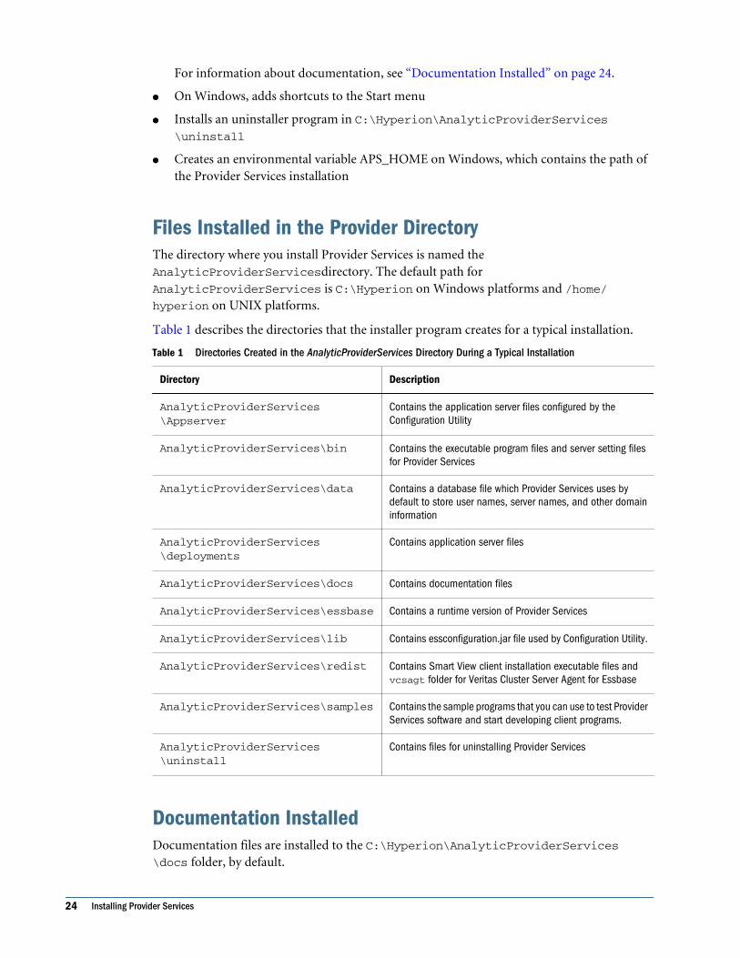
Files Installed in the Provider DirectoryThe directory where you install Provider Services is named theAnalyticProviderServicesdirectory. The default path forAnalyticProviderServices is C:\Hyperion on Windows platforms and /home/hyperion on UNIX platforms.
Table 1 describes the directories that the installer program creates for a typical installation.
Table 1 Directories Created in the AnalyticProviderServices Directory During a Typical Installation
Directory Description
AnalyticProviderServices\Appserver
Contains the application server files configured by theConfiguration Utility
AnalyticProviderServices\bin Contains the executable program files and server setting filesfor Provider Services
AnalyticProviderServices\data Contains a database file which Provider Services uses bydefault to store user names, server names, and other domaininformation
AnalyticProviderServices\deployments
Contains application server files
AnalyticProviderServices\docs Contains documentation files
AnalyticProviderServices\essbase Contains a runtime version of Provider Services
AnalyticProviderServices\lib Contains essconfiguration.jar file used by Configuration Utility.
AnalyticProviderServices\redist Contains Smart View client installation executable files andvcsagt folder for Veritas Cluster Server Agent for Essbase
AnalyticProviderServices\samples Contains the sample programs that you can use to test ProviderServices software and start developing client programs.
AnalyticProviderServices\uninstall
Contains files for uninstalling Provider Services
Documentation InstalledDocumentation files are installed to the C:\Hyperion\AnalyticProviderServices\docs folder, by default.
24 Installing Provider Services

Table 2 Files in the Provider Services docs Directory
File or Folder Name Description
ess_japi_html Javadoc files for the Essbase Java API
images Graphic files for the Provider Services information map
aps_new_features.pdf Provider Services New Features document
aps_info_map.htm Provider Services information map
japistart.htm Launch page for the Essbase Java API Javadocs
Browser RecommendationsFor best results, Hyperion recommends viewing Smart View online help in Internet Explorerversion 6.0 or later or in Netscape Navigator version 7.0 or later. Certain features of the helpsystem, however, are not supported by Netscape Navigator.
On UNIX platforms, if you use Netscape Navigator to view the help system, you must openNetscape before you attempt to launch the help system.
About Hyperion HomeWhen multiple Hyperion products are installed on one computer, common internal and third-party components are installed to a central location, called Hyperion Home. On Windows, theHyperion Home location is defined in the system environment variable calledHYPERION_HOME. On UNIX, the Hyperion Home value is stored in .hyperion.<hostname>in the home directory.
Note:
On UNIX, to ensure that all installers have the permissions required to modify theHYPERION_HOME location, Hyperion recommends that all Hyperion applications be installedunder one HYPERION user account.
Hyperion Home LocationThe default location for Hyperion Home is C:\Hyperion for Windows, and $HOME/Hyperion for UNIX. When you install, the installer searches for the HYPERION_HOMEenvironment variable on the computer to which you are installing.
If the Hyperion Home location was previously defined for another Hyperion product, theinstallation uses the previously defined location. The location cannot be changed through theinstaller.
If the current installation is the first Hyperion installation on the computer, you can specify thelocation during installation.
About Hyperion Home 25

Note:
On UNIX, if the HYPERION_HOME directory is mounted on an NFS so that oneHYPERION_HOME location is visible across multiple computers, Shared Services can beinstalled to only one computer. If you try to install Shared Services to an additional computer,the previous installation is detected.
Files Installed in the HYPERION_HOME DirectoryVarious files are installed in the HYPERION_HOME\common directory for Windows orHYPERION_HOME/common directory for UNIX by a default installation of Shared Services. Somecommon components, and thus some files and folders, are optional and may not be installed.
Table 3 Common-Component Folders Created in the Common Directory
Folder Contents
appServers Application server files
CLS License services APIs
config Hyperion Configuration Utility files
CSS Files to support Hyperion external authentication
Docs Product documentation files
EssbaseJavaAPI Java driver used when embedding Essbase in other applications
EssbaseRTC Essbase runtime client used when embedding Essbase in other applications
httpServers Apache web server files for batteries included installation
HyperionLookAndFeel Installer user interface files
JakartaCommons Common development library files
JavaMail Files to support sending e-mail via Java
JCE JCE files for encryption, key generation and agreement, and MAC
JDBC JDBC files
lib Shared Services library files
loggers Files for external authentication logging
ODBC ODBC drivers
Opatch Oracle patching tool files; for future use
PERL Scripting language files
SAP SAP files
26 Installing Provider Services

Folder Contents
utilities Utilities to change the location of Hyperion Home and export, import, or validateprovisioning data
validation Not used in this release
velocity Not used in this release
XML Common XML components
Changing the Hyperion Home LocationAfter Hyperion Home is defined through the product installation, you can run a migration utilityto change the Hyperion Home location.
On Windows, the migration utility moves the files installed in Hyperion Home to the newlocation and updates the value of the HYPERION_HOME environment variable.
On UNIX, the migration utility updates the .hyperion.<HOSTNAME> file, which resides inthe directory that contains the environment variable. Login initialization files, suchas .profile and .login are not updated.
Hyperion Home Migration Utility is provided with the Shared Services installation.
Note:
For an Apache Tomcat 5.0.28 Windows installation, you can install the Shared Services serveras a Windows service. If you select this option, the Shared Services server is launchedautomatically by the service and runs in the background. However, if you change theHYPERION_HOME location, the Windows service does not automatically start. This problemoccurs because the registry entries for the Windows service retain the old path information. Tosolve this problem, you must manually update the location of the Windows service.
➤ To change the Hyperion Home location:
1 Launch the migration utility:
● On Windows, choose a method:
❍ Select Start > Programs > Hyperion > Foundation Services > Home MigrationUtility.
❍ Double-click the run.exe file from <HYPERION_HOME>\common\utilities\HyperionHomeTool\9.3.1\bin.
❍ From a Windows console, change to <HYPERION_HOME>\common\utilities\HyperionHomeTool\9.3.1\bin. Then type run.exe -console.
● On UNIX, choose a method:
❍ In XWindows, change to <HYPERION_HOME>/common/utilities/HyperionHomeTool/9.3.1/bin. Then type migrationtool.sh.
About Hyperion Home 27

❍ In a UNIX console, change to <HYPERION_HOME>/common/utilities/HyperionHomeTool/9.3.1/bin. Then type migrationtool.sh -console.
2 Step through the screens, and when prompted, enter the Hyperion Home location or click Browse to navigateto the preferred location.
Do not choose a HYPERION_HOME location that contains a space character. For example:
● On Windows, C:\Program Files is not acceptable.
● On UNIX, $HOME/Program Files is not acceptable.
Selecting the ESSLANG ValueThe Provider Services installer prompts you to select a value for the ESSLANG environmentvariable. ESSLANG points Provider Services to the correct Global C code page. The default valuefor ESSLANG is English_UnitedStates.Latin1@Binary.
The Provider Services installer provides a list of supported locales.
ESSLANG must be the same on the Provider Services computer and on the Essbase Servercomputer. The ESSLANG value for a computer must agree with the encoding of the operatingsystem of that computer.
Note:
For important information about ESSLANG and Unicode applications on Essbase Server, see theHyperion Essbase - System 9 Installation Guide.
On Windows, the ESSLANG value selected during installation creates or replaces the ESSLANGsystem environment variable with the selected locale.
On Windows, if ESSLANG is set on the computer to which you are installing Provider Services,the existing value is selected by default in the installer. On UNIX, the installer defaults toEnglish (Latin1), even if ESSLANG is set to a different value. When the installer prompts you,you must select the value of the existing ESSLANG setting; otherwise, your applications may failto start.
28 Installing Provider Services

3Configuring Provider Services
In This Chapter
Hyperion Configuration Utility . . . . . . . . . . . . . . . . . . . . . . . . . . . . . . . . . . . . . . . . . . . . . . . . . . . . . . . . . . . . . . . . . . . . . . . . . . . . . . . . . . . . . . . . . . . . . . . . . . . . .29
Satisfying Initial Requirements ... . . . . . . . . . . . . . . . . . . . . . . . . . . . . . . . . . . . . . . . . . . . . . . . . . . . . . . . . . . . . . . . . . . . . . . . . . . . . . . . . . . . . . . . . . . . . . . . .30
Before You Run Hyperion Configuration Utility . . . . . . . . . . . . . . . . . . . . . . . . . . . . . . . . . . . . . . . . . . . . . . . . . . . . . . . . . . . . . . . . . . . . . . . . . . . . . . . . . .30
Configuring Product Upgrades ... . . . . . . . . . . . . . . . . . . . . . . . . . . . . . . . . . . . . . . . . . . . . . . . . . . . . . . . . . . . . . . . . . . . . . . . . . . . . . . . . . . . . . . . . . . . . . . . . .31
Configuring Provider Services . . . . . . . . . . . . . . . . . . . . . . . . . . . . . . . . . . . . . . . . . . . . . . . . . . . . . . . . . . . . . . . . . . . . . . . . . . . . . . . . . . . . . . . . . . . . . . . . . . . . .31
Integrating Provider Services with SiteMinder . . . . . . . . . . . . . . . . . . . . . . . . . . . . . . . . . . . . . . . . . . . . . . . . . . . . . . . . . . . . . . . . . . . . . . . . . . . . . . . . . .37
Reconfiguring Products .. . . . . . . . . . . . . . . . . . . . . . . . . . . . . . . . . . . . . . . . . . . . . . . . . . . . . . . . . . . . . . . . . . . . . . . . . . . . . . . . . . . . . . . . . . . . . . . . . . . . . . . . . .37
Hyperion Configuration UtilityHyperion Configuration Utility is a common tool that installs automatically with Hyperionproducts. Although you must use it to set up new products that you install, it also enables youto reconfigure existing products and upgraded products. Configuration involves these tasks:
● Product option activation — To comply with your license agreement, select the productfeatures that you are authorized to use.
● Shared Services registration — To use Shared Services to provision and share users amongHyperion product applications. You must register Provider Services with Shared Servicesonly if you use Shared Services to connect Provider Services with Smart View.
● Application server deployment—To deploy the application automatically, or partially, toan application server.
● Shared Services deregistration — To deregister products from with Shared Services beforeupgrading or uninstalling these products.
For information about the order of configuration tasks, acceptable characters, and resolvingconfiguration issues, see:
● “Task Sequence ” on page 30
● “Restricted Characters ” on page 30
● “Troubleshooting ” on page 30
Hyperion Configuration Utility 29

Task Sequence Hyperion recommends that you configure products separately and perform all configurationtasks. However, you can configure products simultaneously performing all, or specific,configuration tasks.
Restricted Characters Only enter alphanumeric, dash (-), dot (.) , underscores (_), and tildes (~) during configuration.Tildes are only supported on Microsoft Windows. All other characters are not supported.
Troubleshooting Terminating configuration for one product does not stop the configuration of other products.All configuration warnings and errors are logged as follows:
Microsoft Windows — <HYPERION_HOME>\logs\config
UNIX — $HYPERION_HOME/logs/config
If you encounter errors, perform these tasks:
● Configure products individually.
● See the Hyperion Installation and Configuration Troubleshooting Guide for information aboutconfiguration checks, debugging using logs, troubleshooting methodology, and solutionsto common configuration issues.
Satisfying Initial RequirementsIf you are using Hyperion Configuration Utility for the first time, perform these tasks:
Table 4 Configuration Requirements
Task Reference
Satisfy system and product-specific requirements. “System Requirements” and “Planning HyperionInstallations” in the Hyperion Installation Start Here
Gather the information you need to configure products. “Hyperion Configuration Utility Worksheets” in the HyperionInstallation Start Here
Install, configure, and start the Shared Services server. Hyperion Shared Services Installation Guide
Before You Run Hyperion Configuration UtilityIf you plan to manually configure Provider Services with a custom deployment port, you mustedit the APS.instance file to match your deployment settings.
30 Configuring Provider Services

Note:
Perform this procedure before running Hyperion Configuration Utility to register ProviderServices with Shared Services.
➤ To edit the APS.instance file:
1 Open the file <APS_HOME>\data\APS.instance in a text editor.
2 Change protocol="http" and port="13080" to match your deployment settings.
The section below highlights the items that you must change:
<?xml version="1.0" encoding="UTF-8" ?><registration><instance product="APS" vdir="SVProvider"><connection name="OfficeAddinProtocol" protocol="http" server="" port="13080" uri="/aps/SmartView" /><attribute type="xsd:boolean" name="OfficeAddinSupport" value="true" version="1.0" /><instance></registration>
Configuring Product UpgradesYou can use Hyperion Configuration Utility to configure and reconfigure supported productupgrades. Note the following:
● If you upgraded Shared Services, configure it before configuring other products.
● Configure upgraded products individually.
● Deploy to the same database you used when you configured the previous product release.
If you do not want to use Shared Services with the products you are upgrading, select SharedServices Deregistration during configuration.
Configuring Provider ServicesRun Hyperion Configuration Utility on the computer hosting the products to configure orreconfigure.
➤ To configure Provider Services:
1 Launch Hyperion Configuration Utility as follows:
● At the end of installation by selecting Launch Hyperion Configuration Utility on the lastpanel.
● Using a method:
On Microsoft Windows:
❍ Select Start > Programs > Hyperion > Foundation Services > Configuration Utility.
Configuring Product Upgrades 31

❍ Double-click configtool.bat in <HYPERION_HOME>\common\config.
❍ Change to<HYPERION_HOME>\common\config and type startconfigtool.bat —console.
On UNIX:
❍ Change to <HYPERION_HOME>/common/config and type configtool.sh .
❍ Change to <HYPERION_HOME>/common/config and type configtool.sh —console.
2 Select the language in which to configure and click Next.
3 On the Welcome page, click Next.
4 Select the products and the tasks to perform, then click Next.
5 Based on your selection, perform the following tasks, clicking Next between tasks.
Table 5 Configuration Tasks
Selection Task
Shared Services Registration See “Registering With Shared Services ” on page 33.
Deploy to Application Server a. Start the application server.
b. Select the application server, then an option:
● Automatic— Hyperion Configuration Utility deploys all files to the applicationserver, resulting in no or minimal post-deployment tasks:
❍ WebLogic: If disk space is inadequate, specify another location for theWAR file and redeploy.
❍ WebSphere: If disk space is inadequate, Hyperion Configuration Utilityplaces java.io.tempdir in <HYPERION_HOME>\temp in Windows:<HYPERION_HOME>/temp in UNIX. After deployment, the temp folderis deleted.
● Manual— The EAR or WAR file is placed in this directory, enabling you tomanually deploy after configuration:
Windows: <ProductHome>\<AppServer>\InstallableApps\common
UNIX: ProductHome>/<AppServer>/InstallableApps/common
Windows: WebLogic 8.1.6 — <ProductHome>\<AppServer>\InstallableApps
UNIX: WebLogic 8.1.6 —<ProductHome>/<AppServer>/InstallableApps
c. Enter the information in “Deploying to the Application Server ” on page 35.
On WebLogic, a default username and password of hyperion is used internally fordeployment.
Tip: For simplicity, Hyperion recommends that you use the same application server,and domain or profile.
Integrate with SiteMinder See “Integrating Provider Services with SiteMinder ” on page 37
6 Click Finish.
32 Configuring Provider Services

Configuration time depends on the products and tasks you selected. Progress is recorded inconfigtool.log as follows:
Windows:<HYPERION_HOME>\logs\config
UNIX:<HYPERION_HOME>/logs/config
When configuration finishes, the status of each task is displayed.
If configuration is successful, perform any required post-configuration tasks and start theproduct.
If errors display, perform these tasks:
● Configure products individually and perform tasks separately.
● See the Hyperion Installation and Configuration Troubleshooting Guide for informationabout resolving configuration issues.
Registering With Shared Services By default, the user you specify during registration is pre-provisioned as admin. This enablesyou to log on toShared Services after configuration using admin/password, to create andprovision users.
Table 6 Shared Services Registration
Field Description
Server Name The name of the computer where the Shared Services server is installed.
Caution! Do not specify an IP address, especially in DHCP environments, or enter restrictedcharacters.
Port The default or custom Shared Services server port number.
User The username of the Shared Services Administrator.
Password the password of the Shared Services Administrator.
SSL Select to use Secure Sockets Layer for encryption. See the Hyperion Product SSL ConfigurationGuide.
You need to register Provider Services with Shared Services only if you use Shared Services toconnect Provider Services and Smart View. You can register Provider Services as follows:
● If you are upgrading both Provider Services and Shared Services server to the sameversion, use the Hyperion Configuration Utility.
● If you are upgrading Provider Services but not Shared Services (or if they are of differentversions), use the registration tool. The registration tool is a script provided with ProviderServices.
➤ To register Provider Services with Shared Services using the registration tool:
1 Before installing the new version of Provider Services, back up and save the following files. (You will needthese files later after installation):
Configuring Provider Services 33

● <ESS_ES_HOME>\data\aps.product, aps.instance, and css.xml
● <ESS_ES_HOME>\bin\essbase.properties
● <ESS_ES_HOME>\lib\ees_es_gui.jar
2 Install Provider Services as described in Chapter 2, “Installing Provider Services”. Do not run the HyperionConfiguration Utility.
3 Copy the files that you saved in step 1 to the same locations in the newly-installed Provider Services directory,replacing the newer version of these files. This step enables the registration tool to select the correct SharedServices client .jar files in the classpath to register Provider Services.
4 Ensure that Shared Services is running and that Provider Services is shut down.
5 If necessary, use a text editor to edit the files that you saved in step 1 and copied in step 3 to reflect yourProvider Services deployment:
● <ESS_ES_HOME>\bin\essbase.properties—edit the following line (see definitions inthe file) :
nativeSecurity.css.config.file.name=<http|https>://<hubServer>:<hubPort>/interop/framework/getCSSConfigFile
hubServer=<hubServer>;<http|https>
hubPort=<hubPort>
applicationRegistrationFile=<ESS_ES_HOME>/data/APS.instance
● <ESS_ES_HOME>\data\APS.instance—update the following line with the protocol,hostname, and port where Provider Services is deployed:
<connection name="OfficeAddinProtocol" protocol="http" server="" port="13080" uri="/aps/SmartView" />
Note:
If Provider Services is running on the Secured Socket Port, use protocol="https"
● <ESS_ES_HOME>\bin — edit the following values in registerAPS.cmd in Windows orregisterAPS in UNIX
<HUB_USER><HUB_PASSWORD>
● UNIX only: edit properties in registerAPS as appropriate.
6 Edit <ESS_ES_HOME>\bin\registerAPS.cmd in Windows or <ESS_ES_HOME>/bin/registerAPS in UNIX as follows:
Replace the line
set CLASSPATH=%ESS_ES_HOME%\lib\ess_japi.jar;%ESS_ES_HOME%\lib\ess_es_server.jar;%EXTERNAL_JARS%;
with
set CLASSPATH=%ESS_ES_HOME%\lib\ess_japi.jar;%ESS_ES_HOME%\lib\ess_es_server.jar;%EXTERNAL_JARS%;%ESS_ES_HOME%\lib\ess_css_register.jar;
7 To execute the registration tool, run the following script:
34 Configuring Provider Services

Windows: <ESS_ES_HOME>\bin\registerAPS.cmd
UNIX: <ESS_ES_HOME>/bin/registerAPS
Deploying to the Application Server To prevent the Web application being deployed from inheriting unwanted runtime settings, youmust create and use one of the following:
● Oracle OC4J instance
● WebLogic server
● WebSphere application server
Deploying more than one Web application to the same OC4J instance, WebLogic server, orWebSphere application server may yield unsuccessful results.
Table 7 Deployment
Field Description
Location Path to the application server installation directory:
● WebSphere Base:
Windows: c:\WebSphere\AppServer
UNIX: /opt/WebSphere/AppServer
● WebSphere Express:
Windows: c:\IBM\WebSphere\Express51\AppServer
UNIX:/opt/IBM/WebSphere/Express51/AppServer
● WebLogic 8.1.6:
Windows: c:\bea\weblogic81
UNIX: /opt/bea/weblogic81
● WebLogic 9.1:
Windows: c:\bea\weblogic91
UNIX: /opt/bea/weblogic91
Deploy as a service Selected by default to register the web application as a Windows service listed in WindowsControl Panel. See “Startup Dependencies” in the Hyperion Installation Start Here.
Profile (WebSphere) Name of the profile where you access the application. By default, all applications deploy tothe same profile. To change the profile name, see “What Happens During Deployment ” onpage 36.
Domain (WebLogic) Default name of the domain where you access the application. For WebLogic 9.1.x, allapplications deploy to the same domain. To change the domain name, see “What HappensDuring Deployment ” on page 36.
BEA Home (WebLogic) Path to the BEA Home directory (e.g., c:\ or /opt/)
Component Products being deployed. Some products display as components.
Configuring Provider Services 35

Field Description
Server Name Enter the name of the server where you will access the product. Do not include spaces. Thisname is used as the product directory name in <HYPERION_HOME> deployments.
Port To change the default port, enter a unique port number that does not exceed 1025 to avoidconflicts with third-party port assignments. See “Ports” in the Hyperion Installation StartHere.
What Happens During Deployment
WebSphere and WebLogic 9.1.Hyperion Configuration Utility deploys each application to the same WebSphere profile orWebLogic domain. The profile or domain is created when the first application is deployed. Eachapplication runs in a separate JVM.
Hyperion Configuration Utility deploys the application to:
Windows: HYPERION_HOME\deployments\<AppServNameAndVersion>
UINX: HYPERION_HOME/deployments/<AppServNameAndVersion>
Under this directory, the bin directory contains start and stop scripts for all deployedapplications. For each application, there is also a setCustomParams<Product>.bat file or ashell script where JAVA_OPTIONS can be changed when starting using start scripts.
To change the default profile or domain directory, modify the deployment directory parameterin the weblogic.properties or websphere.properties in:
Windows:HYPERION_HOME\common\config\resources\<AppServName>\resources
UNIX: HYPERION_HOME/common/config/resources/<AppServName>/resources
Note:
It is not recommended to change other parameters in this file.
WebLogic 8.1.6Deploying to a single domain for WebLogic 8.1.6 is not supported. For WebLogic 8.1.6, HyperionConfiguration Utility deploys the application to:
Windows: PRODUCT_HOME\AppServer\InstalledApps\<AppServName>\<Version>
UNIX:PRODUCT_HOME/AppServer/InstalledApps/<AppServName>/<Version>
36 Configuring Provider Services

Integrating Provider Services with SiteMinder
➤ To integrate Provider Services with SiteMinder:
1 Ensure that Provider Services, Essbase, Shared Services, and Smart View are installed.
2 Ensure that Provider Services and Essbase are configured for Shared Services.
3 Ensure that Siteminder integration into your environment is complete and that trial logins to protectedresources are possible.
4 In Siteminder, verify that a successful authentication modifies the http header to hyplogin. This variablecan be read into the Smart View provider for subsequent processing.
5 If you want to change hyplogin to a different name, open <HYPERION_HOME/AnalyticProviderServices/bin/essbase.properties and edit the property below, thenrestart Provider Services.
smartview.webservice.sso.httpheader.property.username=
6 Ensure that Shared Services is enabled for single sign-on.
7 If you are using HTML form-based authentication, make sure that the HTML form-based authentication pagecan be viewed from a browser.
8 Ensure that a login form similar to the one viewed from the browser can be accessed from Smart View.
Subsequent operations with Smart View should be possible.
9 To verify the sucess of the setup, check the apsserver.log file. For each request from Smart View toProvider Services, an entry similar to the following will be logged:
DEBUG [Servlet.Engine.Transports : 0]: - Time: Tue Jul 24 19:11:28 MEST 2007, smUser hyplogin : user1
Reconfiguring Products Hyperion Configuration Utility enables you to reconfigure products to incorporate changes inyour environment such as a different application server.
To reconfigure, launch Hyperion Configuration Utility on the computer hosting the product,and follow the procedures in this chapter.
Note:
If you reconfigure a database, restart the application server afterward.
Integrating Provider Services with SiteMinder 37

38 Configuring Provider Services

4Starting Shared Services and
Provider Services
In This Chapter
Verifying Startup Dependencies ... . . . . . . . . . . . . . . . . . . . . . . . . . . . . . . . . . . . . . . . . . . . . . . . . . . . . . . . . . . . . . . . . . . . . . . . . . . . . . . . . . . . . . . . . . . . . . . .39
Starting and Stopping Shared Services... . . . . . . . . . . . . . . . . . . . . . . . . . . . . . . . . . . . . . . . . . . . . . . . . . . . . . . . . . . . . . . . . . . . . . . . . . . . . . . . . . . . . . . .39
Verifying Startup DependenciesBefore starting Provider Services, verify that Shared Services server is running.
Starting and Stopping Shared Services
Starting Shared ServicesIf you deployed the Shared Services application server as a Windows service, to start SharedServices manually, from the Windows control panel, select Administrative Tools > Services.
➤ If you did not deploy Shared Services application server as a Windows service, to start the SharedServices server
1 Select Start > Programs > Hyperion > Foundation Services > Start Shared Services.
2 If the menu item does not indicate the application server to which the Shared Services server is deployed,you must start Shared Services server manually.
➤ To start Shared Services server manually, execute the startup script:
Application Server Path to Script
IBM WebSphere Windows:
<HYPERION_HOME>\deployments\<AppServNameAndVersion>\bin\startSharedServices9.bat
UNIX:
<HYPERION_HOME>/deployments/<AppServNameAndVersion>/bin/startSharedServices9.sh
Verifying Startup Dependencies 39

Application Server Path to Script
BEA WebLogic 8.1.6 Windows:
<HSS_HOME>\AppServer\InstalledApps\<AppServName>\<version>\SharedServices9\startSharedServices.bat
UNIX:
<HSS_HOME>/AppServer/InstalledApps/<AppServName>/<version>/SharedServices9/startSharedServices.sh
BEA WebLogic 9.1. Windows:
<HYPERION_HOME>\deployments\<AppServNameAndVersion>\bin\startSharedServices.bat
UNIX:
<HYPERION_HOME>/deployments/<AppServNameAndVersion>/bin/startSharedServices.sh
Oracle To start Oracle Enterprise Manager:
Windows:
<OracleInstallDir>\bin\emctl start iasconsole
<OracleInstallDir>/bin/emctl start iasconsole
To start all managed applications under Oracle Enterprise Manager:
Windows:
<OracleInstallDir>\opmn\bin\opmnctl startall
UNIX:
<OracleInstallDir>/opmn/bin/opmnctl startall
To start OC4J instance:
Windows:
<OracleInstallDir>\opmn\bin\opmnctl start process-type=<instance-name>
UNIX:
<OracleInstallDir>/opmn/bin/opmnctl start process-type=<instance-name>
where Shared Services has been deployed to instance “<instance-name>”.
Apache Tomcat Windows:
<HYPERION_HOME>\deployments\<AppServName>\<version>\bin\startSharedServices9.bat
UNIX:
<HYPERION_HOME>/deployments/<AppServName>/<version>/bin/startSharedServices9.sh
40 Starting Shared Services and Provider Services

Verifying Successful Startup of Shared Services
➤ To verify successful startup and configuration of Shared Services:
1 During startup, look for the following confirmation messages in the Shared Services console window:
● Database Configuration Test Passed
● Security System Initialized Successfully
Note:
This message will not display for Tomcat.
● Shared Services Initialized Successfully
On UNIX, when Shared Services is deployed to the Tomcat application server, confirmationmessages are logged to <HYPERION_HOME>/deployments/<AppServName>/<version>/SharedServices9/logs/Catalina.out.
When Shared Services is deployed to WebSphere, the confirmation message is logged to<WebSphereInstallDir>\AppServer\logs\SharedServices9\SystemOut.log
on Windows; <WebSphereInstallDir>/AppServer/logs/SharedServices9/SystemOut.log on UNIX.
When Shared Services is deployed to WebLogic 8.1.6, if the log level is not set to WARN,the confirmation message is logged to <HSS_HOME>\AppServer\InstalledApps\WebLogic\8.1\SharedServices9\logs\SharedServices_Metadata.log onWindows; <HSS_HOME>/AppServer/InstalledApps/WebLogic/8.1/SharedServices9/logs/SharedServices_Metadata.log on UNIX.
When Shared Services is deployed to WebLogic 9.1 if the log level is not set to WARN, theconfirmation message is logged to <HYPERION_HOME>\deployments\WebLogic9\SharedServices9\logs\SharedServices_Metadata.log on Windows;<HYPERION_HOME>/deployments/WebLogic9/SharedServices9/logs/
SharedServices_Metadata.log on UNIX.
2 On the Shared Services server computer, launch the Oracle's Hyperion® Shared Services User ManagementConsole login page by opening a browser and entering this URL:
http://SharedServicesServerName:port#/interop
where SharedServicesServerName is the name of the computer where the Shared Servicesserver is installed and port# is the port number of the Shared Services server. The default portnumber is 58080; if Shared Services server is installed to a non-default port, specify that value.For example, using the default port:
http://jdoe:58080/interop/
Note:
As a best practice, the URL should use an IP address or a fully qualified machine name thatincludes the domain name. If the IP address is dynamic, use the fully qualified machine name.
Starting and Stopping Shared Services 41

Note:
Optionally, on Windows, you can select Start > Programs > Hyperion > Foundation Services> User Management Console
Display of the Oracle's Hyperion® Shared Services User Management Console login pageindicates that the Shared Services server started successfully.
Stopping Shared ServicesIf you installed the Shared Services application server as a Windows service, to stop SharedServices server, use the Windows control panel.
➤ To stop Shared Services server manually:
1 Execute the stop script:
Application Server Path to Script
IBM WebSphere Windows:
<HYPERION_HOME>\deployments\<AppServNameAndVersion>\bin\stopSharedServices9.bat
UNIX:
<HYPERION_HOME>/deployments/<AppServNameAndVersion>/bin/stopSharedServices9.sh
BEA WebLogic 8.1.6 Windows:
<HSS_HOME>\AppServer\InstalledApps\<AppServName>\<version>\SharedServices9\stopSharedServices.bat
UNIX:
<HSS_HOME>/AppServer/InstalledApps/<AppServName>/<version>/SharedServices9/stopSharedServices.sh
BEA WebLogic 9.1 Windows:
<HYPERION_HOME>\deployments\<AppServNameAndVersion>\bin\stopSharedServices.bat
UNIX:
<HYPERION_HOME>/deployments/<AppServNameAndVersion>/bin/stopSharedServices.sh
Oracle To stop Oracle Enterprise Manager:
Windows:
<OracleInstallDir>\bin\emctl stop iasconsole
UNIX:
<OracleInstallDir>/bin/emctl stop iasconsole
42 Starting Shared Services and Provider Services

Application Server Path to Script
To stop all managed applications under Oracle Enterprise Manager:
Windows:
<OracleInstallDir>\opmn\bin\opmnctl stopall
UNIX:
<OracleInstallDir>/opmn/bin/opmnctl stopall
To start OC4J instance:
Windows:
<OracleInstallDir>\opmn\bin\opmnctl stop process-type=<instance-name>
UNIX:
<OracleInstallDir>/opmn/bin/opmnctl stop process-type=<instance-name>
where Shared Services has been deployed to instance “<instance-name>”.
Apache Tomcat Windows:
<HYPERION_HOME>\deployments\<AppServName>\<version>\bin\stopSharedServices9.bat
UNIX:
<HYPERION_HOME>/deployments/<AppServName>/<version>/bin/stopSharedServices9.sh
Note:
On Windows systems, you can optionally select Start > Programs > Hyperion > FoundationServices > Stop Shared Services
2 On WebLogic, if a message that suggests using the FORCESHUTDOWN command is displayed, use theFORCESHUTDOWN command to stop Shared Services server:
a. In a text editor, open the stop script.
See the table under Step 1 for the stop script location.
b. In the file, find SHUTDOWN, and replace it with FORCESHUTDOWN.
c. Save and execute the file.
Testing the Provider Services InstallationAfter installing Provider Services, test the installation to ensure that Provider Services is installedcorrectly.
➤ To test the Provider Services installation:
1 Start Provider Services.
Starting and Stopping Shared Services 43

Note:
Before starting Provider Services, ensure that all Essbase Servers are added to the ProviderServices node in Administration Services Console. See “Connecting to a Stand-alone EssbaseServer” on page 57.
2 Open a Web browser window and type the Provider Services URL:
http://<servername>:13080/aps/APS
The Web browser should display the message “Provider Services.”
Note:
13080 is the default port. Your Provider Services instance may be deployed on a different port.Check with your system administrator.
Testing the Smart View ConnectionAfter ensuring thatProvider Services is installed correctly, you can test the client connection, forexample, to Smart View.
➤ To test the connection through Smart View:
1 Install Smart View.
See “Installing the Smart View Client” on page 22.
2 Install Essbase and start Essbase Server.
See the Hyperion Essbase - System 9 Installation Guide.
3 Start Provider Services.
4 Open a Microsoft Office application, such as Excel.
5 From the Hyperion menu, select Connection Manager.
6 Follow the prompts to add a data source. Select URL Provider to connect to Provider Services:
For user name and password, use the Essbase Server login information.
For the provider URL, use the Provider Services URL:
http(s)://<servername>:<port#>/aps/SmartView
For example:
http://localhost:13080/aps/SmartView
7 After successfully adding Provider Services as a data source, double-click the Provider Services name inConnection Manager to connect to it and start working with Smart View.
See Smart View for Office User's Guide or online help for information on using Smart View.
44 Starting Shared Services and Provider Services

Starting Provider ServicesAfter installing Provider Services, start Provider Services.
Note:
The command to startProvider Services on Windows or UNIX differs depending on the webapplication server on which you deployed Provider Services.
On WindowsIf Provider Services is not running as a service, use one of the procedures in this section tomanually start it.
➤ To start Provider Services from the Start menu, select Start > Programs > Hyperion >ProviderServices > Start Provider Services.
When Provider Services starts, a DOS window is displayed.
Note:
You can also use the out-of-the-box Tomcat configuration to start Provider Services withoutcompleting any deployment steps. To use this configuration, select Start > Programs > HyperionSystem 9 BI+ > Provider Services > Start Analytic Provider.
➤ To start Provider Services by running a .bat file:
1 At a command prompt, change to the HYPERION_HOME\AnalyticProviderServices\bindirectory and locate the start<web_application_server>aps.bat file.
For example, if you deployed Provider Services on Apache Tomcat,startAPSTomcat5aps.bat is the file to use.
2 Run the appropriate .bat file; for example:
>startAPSTomcat5aps.bat
When Provider Services starts, a DOS window is displayed.
On UNIXUse the procedures in this section to start Provider Services either in the foreground or in thebackground.
➤ To start Provider Services in the foreground:
1 At a command prompt, change to the HYPERION_HOME/Analytic Provider Services/bindirectory, and locate the start<web_application_server>aps.sh file.
Starting and Stopping Shared Services 45

For example, startAPSTomcat5028server1.sh is the file to use if you deployed ProviderServices on Apache Tomcat.
2 Run the .sh file; for example:
>startAPSTomcat5028server1.sh
➤ To start Provider Services in the background, from the <APS_HOME>//bin directory, type:
./ StartAPSTomcatServer.sh &
or
nohup ./StartAPSTomcatServer.sh &
Using the nohup command sends the output to nohup.out.
When Provider Services starts, a text-mode Agent process window is displayed.
Stopping Provider Services After you finish using Provider Services, you can stop the provider instance.
➤ To stop Provider Services, launch one of the following files:
● On Windows platforms, launch
APS_HOME\bin\StopAPSTomcatServer.bat
Note:
If you chose to add shortcuts to the Start menu during installation, you can stop ProviderServices from the Start menu (Start > Programs > Hyperion System 9 BI+ > Provider Services> Stop Analytic Provider).
● On UNIX platforms, launch
APS_HOME/bin/StopAPSTomcatServer.sh
46 Starting Shared Services and Provider Services

5Uninstalling Provider Services
and Smart View
In This Chapter
Uninstalling Provider Services ... . . . . . . . . . . . . . . . . . . . . . . . . . . . . . . . . . . . . . . . . . . . . . . . . . . . . . . . . . . . . . . . . . . . . . . . . . . . . . . . . . . . . . . . . . . . . . . . . .47
Uninstalling the Smart View Client .. . . . . . . . . . . . . . . . . . . . . . . . . . . . . . . . . . . . . . . . . . . . . . . . . . . . . . . . . . . . . . . . . . . . . . . . . . . . . . . . . . . . . . . . . . . . . .47
Uninstalling Provider ServicesThe uninstaller program does not remove the following information:
● The common components that reside in the HYPERION_HOME\common directory(Windows) or HYPERION_HOME/common directory (UNIX)
● Other files or directories that are created or modified after installation
➤ To uninstall Provider Services:
1 Stop all instances of Provider Services.
2 Launch the uninstaller program for your platform, where APS_PATH represents the directory where youinstalled Provider Services.
Table 8 Provider Services Uninstaller Program
Platform Uninstaller Program
Windows APS_PATH\AnalyticProviderServices\uninstall\uninstall.exe
UNIX APS_PATH/AnalyticProviderServices/uninstall/uninstall.bin
Note:
On Windows platforms, you can also uninstall from the Control Panel (Add/Remove Programs).
3 Follow the uninstaller prompts.
4 After the uninstallation is complete, delete the APS_PATH\AnalyticProviderServices directory.
Uninstalling the Smart View ClientYou must run an uninstaller program to uninstall Smart View.
Uninstalling Provider Services 47

To preserve login and user preference information, the following registry items remain afteruninstalling Smart View:
HKEY_CURRENT_USER\Software\Hyperion Solutions\
HyperionSmartViewConnections
HKEY_CURRENT_USER\Software\Hyperion Solutions\HyperionSmartViewLogin
HKEY_CURRENT_USER\Software\Hyperion Solutions\
HyperionSmartViewPreferences
➤ To uninstall Smart View:
1 Exit all Microsoft Office applications to ensure a proper uninstallation.
2 Launch the Smart View installer program located at SV_PATH\SmartView\redist\SmartView.exe, where SV_PATH represents the directory where you installed Smart View.
Note:
SmartView.exe serves as the Smart View client installer and uninstaller program. If you have anexisting Smart View client installed, when you run SmartView.exe again, it detects the SmartView installation and provides an option to repair or remove Smart View.
3 Select one of the following options:
● Repair - Fixes errors in the installation, such as missing files, corrupt files, shortcuts, orregistry entries.
● Remove - Removes the Smart View client from your machine.
4 Follow the uninstaller prompts.
Note:
You can also uninstall from the Control Panel (Add/Remove Programs). Smart View client islisted as Hyperion System 9 Smart View for Office.
48 Uninstalling Provider Services and Smart View

6Upgrading Provider Services
and Smart View
In This Chapter
Upgrading Provider Services ... . . . . . . . . . . . . . . . . . . . . . . . . . . . . . . . . . . . . . . . . . . . . . . . . . . . . . . . . . . . . . . . . . . . . . . . . . . . . . . . . . . . . . . . . . . . . . . . . . . .49
Upgrading Smart View Client.. . . . . . . . . . . . . . . . . . . . . . . . . . . . . . . . . . . . . . . . . . . . . . . . . . . . . . . . . . . . . . . . . . . . . . . . . . . . . . . . . . . . . . . . . . . . . . . . . . . . .50
If you are upgrading from a previous release of Hyperion products, note the following supportedupgrade paths:
● 9.2.0.3 to 9.3.1.1
● 9.3.0.x to 9.3.1.1
If you are using a release prior to 9.2.0.3, you must first upgrade to one of the versions notedabove, and then upgrade to 9.3.1.1.
Upgrading Provider ServicesWhen upgrading to a major release, you are required to perform the procedures in this section.
➤ To upgrade Provider Services:
1 Verify all necessary software and documentation are present for this release.
See the Hyperion Installation Start Here.
2 Ensure that you have upgraded to Shared Services 9.3.1 and verify that Essbase users have been migrated(that is, are present in Native Directory).
See the Shared Services Installation Guide and Hyperion Security Administration Guide.
3 Uninstall Analytic Services Smart View Provider 9.2.0.3 or Analytic Provider Services 9.3.0.x.
See Chapter 5, “Uninstalling Provider Services and Smart View.”
4 Install the current version of Provider Services.
See “Installing Provider Services” on page 21.
Note:
Ensure that the current versions of Essbase and Administration Services are also installed. Seethe respective installation guides for each product.
Upgrading Provider Services 49

5 Using the Hyperion Configuration Utility, configure Shared Services as follows:
a. Configure the database, choosing the Reuse existing repository option.
b. Deploy Shared Services on an application server.
Refer to the Shared Services Installation Guide for detailed information on these tasks.
6 In the Hyperion Configuration Utility, register Provider Services with Shared Services. Registering creates therequired project and application instance for Provider Services 9.3.1.1 in Shared Services. See “RegisteringWith Shared Services ” on page 33.
a. Close the Administration Services Console if it is open
b. Manually copy ess_es_gui.jar located in APS_931_INSTALL/lib toEAS_INSTALL/console/lib to EAS_INSTALL/console/lib.
c. Restart the Administration ServicesConsole.
Note:
You need to register Provider Services with Shared Services only if you use Shared Services toconnect Provider Services and Smart View.
7 In the Shared Services User Management Console, verify that a new project and a new application instancefor Provider Services are created.
For example, check if your project exists under Projects > Hyperion Provider Services 9.3.1.1Servers.
Note:
Log into Shared Services User Management console at http://<sharedservcies_server>:58080/interop/. For example, http://localhost:58080/interop/.
Note:
In Provider Services 9.3.1.1 you do not need to provision users for the Provider Servicesadministrator role. User roles are determined by the Essbase Server. See “Administering ProviderServices” on page 55
Upgrading Smart View ClientUse the following process to upgrade Smart View to this release.Pre-release 9.0 Smart Viewclients do not support Provider Services. Pre-release 9.3 Smart View clients support onlyProvider Services. Release 9.0 through pre-release 9.3 Smart View clients support HyperionSystem 9 BI+ Analytic Services Smart View Provider.
50 Upgrading Provider Services and Smart View

Note:
In previous releases of Smart View, the default install directory was C:\Program Files\HyperionSmartView. Starting with Release 9.0, the default install directory is C:\Hyperion\SmartView.
➤ To upgrade Smart View:
1 Verify all necessary software and documentation are present for this release.
2 Place the upgraded Smart View client installer, SmartView.exe or SmartViewHVE.exe (for licensedOracle's Hyperion® Essbase® Visual Explorer users), on a server where your users can install it.
3 Install this release of Smart View.
See “Installing the Smart View Client” on page 22.
4 Start Microsoft Office applications, such as Excel, and ensure that the Hyperion menu is displayed in themenu bar of the Office product.
See “Testing the Smart View Connection” on page 44.
Upgrading Smart View Client 51

52 Upgrading Provider Services and Smart View
7Shared Services User
Management
In This Chapter
About Shared Services User Management .. . . . . . . . . . . . . . . . . . . . . . . . . . . . . . . . . . . . . . . . . . . . . . . . . . . . . . . . . . . . . . . . . . . . . . . . . . . . . . . . . . . . .53
About Shared Services User ManagementShared Services provides a centralized system for managing user and group access to Hyperionproducts. The Shared Services security system consists of corporate or native Shared Servicesuser directories and a common user interface, called User Management Console. The SharedServices user management system enables you to manage and provision users for multipleHyperion products from a central location. Provisioning refers to the process of assigning rolesand access permissions to users. When a server runs in Shared Services security mode, the UserManagement Console performs all user management tasks.
Note:
Starting in Provider Services 9.3.1 you do not need to provision user in Shared Services to haveadministrator role for Provider Services. To perform administrative functions in ProviderServices in Essbase, you must have an administrator role for the designated Essbase in SharedServices. For more information, see Chapter 8, “Administering Provider Services”
PrerequisitesThe procedures in this chapter assume the installation and configuration of these componentsare completed in the following order:
● Hyperion Shared Services Server
● Administration Services
● Essbase
● Provider Services
You should have migrated Administration Services and Essbase users to Shared Services security.
For Provider Services, complete the procedures in Chapter 3, “Configuring Provider Services .”
About Shared Services User Management 53

Compatibility MatrixTable 9 lists the security mode compatibility requirements for each of the following products.
Table 9 Security Mode Compatibility Matrix
Administration Services Security Mode Essbase Security Mode Provider Services Security Mode
Shared Services Shared Services Shared Services
Shared Services or Native Native
Native Native
54 Shared Services User Management

8Administering Provider Services
In This Chapter
Administering Provider Services ... . . . . . . . . . . . . . . . . . . . . . . . . . . . . . . . . . . . . . . . . . . . . . . . . . . . . . . . . . . . . . . . . . . . . . . . . . . . . . . . . . . . . . . . . . . . . . . .55
Configuration Options in essbase.properties .. . . . . . . . . . . . . . . . . . . . . . . . . . . . . . . . . . . . . . . . . . . . . . . . . . . . . . . . . . . . . . . . . . . . . . . . . . . . . . . . . . .65
Analytic Server Clustering Concepts.. . . . . . . . . . . . . . . . . . . . . . . . . . . . . . . . . . . . . . . . . . . . . . . . . . . . . . . . . . . . . . . . . . . . . . . . . . . . . . . . . . . . . . . . . . . . .67
Fault Tolerance ... . . . . . . . . . . . . . . . . . . . . . . . . . . . . . . . . . . . . . . . . . . . . . . . . . . . . . . . . . . . . . . . . . . . . . . . . . . . . . . . . . . . . . . . . . . . . . . . . . . . . . . . . . . . . . . . . . .72
Administering Provider ServicesTo perform administrative functions in Provider Services in Essbase, you must have anadministrator role for the designated Essbase Server in Shared Services. If you have an adminrole, you are automatically given permission to add or administer Provider Services for thatEssbase after logging into Administration Services. Provider Services communicates with thedesignated Essbase server and grants or denies administrator permissions based on the your rolein that Essbase instance.
Use Administration Services Console to administer Provider Services:
● “Adding Provider Services” on page 56
● “Removing Provider Services” on page 56
● “Connecting to a Stand-alone Essbase Server” on page 57
● “Removing a Stand-alone Server” on page 58
● “Connecting to a Cluster of Essbase Servers” on page 58
● “Adding an Analytic Cluster” on page 58
● “Editing the Authenticating Essbase Server” on page 56
● “Removing Analytic Clusters” on page 59
● “Adding a Cluster Component” on page 59
● “Removing a Cluster Component” on page 60
● “Enabling Cluster Components” on page 60
● “Disabling Cluster Components” on page 61
● “Connecting to Provider Services” on page 61
● “Specifying Logging Properties” on page 62
● “Monitoring Sessions” on page 62
Administering Provider Services 55

● “Specifying Session Timeout” on page 63
● “Specifying Maximum Rows and Columns” on page 63
● “Automatically Deploying Client Upgrades” on page 64
● “Fault Tolerance” on page 72
Adding Provider Services
➤ To add Provider Services:
1 From Enterprise View or a custom view, select the Hyperion Provider Services node.
2 Right-click and select Add Hyperion Provider Services.
3 In Add Hyperion Provider Services, in Provider Name, enter the Provider Services server name, such aslocalhost.
4 Click the URL text box. This copies the URL of the Hyperion Provider Server you entered in the previous step.For example, http://localhost:13080/aps/APS.
5 In Authenticating Essbase Server, select the name of the Essbase server from the dropdown list. You musthave an administrator role in this Essbase server to perform administrative actions.
6 Click OK.
The provider name is displayed under the Provider Services node.
Editing the Authenticating Essbase ServerYou can edit the Authenticating Essbase Server that you specified in the previous section whileadding a Provider Services server in EAS.
➤ To edit the authenticating Essbase Server:
1 From Enterprise View or a custom view, under the Hyperion Provider Services node, select a provider.
2 Right-click and select Edit Authenticating Essbase Server.
You will be prompted with a dialog box where you can edit and specify another authenticatingEssbase server.
3 Click OK.
Removing Provider ServicesYou can remove Provider Services when you no longer need to administer it, such as when theserver is no longer in use.
56 Administering Provider Services

➤ To remove Provider Services:
1 From Enterprise View or a custom view, under the Hyperion Provider Services node, select a provider.
2 Right-click and select Remove.
3 In Remove Hyperion Provider Services, click Yes.
Connecting to a Stand-alone Essbase ServerThrough Administration Services Console, Provider Services can connect to stand-alone EssbaseServers or Essbase Server clusters. Smart View, Java API, and XMLA users connect to EssbaseServers through Provider Services. To users, the accessed database is transparent. From theirperspective, they connect to, and retrieve data from, one data source.
Stand-alone servers are single Essbase Servers that are not part of a clustered environment, whichwould enable load balancing and failover support. See “Connecting to a Cluster of EssbaseServers” on page 58 for clustering information.
Note:
To enable users to select any stand-alone Essbase Server, add the stand-alone server to ProviderServices through Administration Services Console. Add Essbase Server to the User Propertieswindow in Administration Services Console before adding the stand-alone server to ProviderServices.
➤ To connect to a stand-alone Essbase Server:
1 From Enterprise View or a custom view, select the Essbase Servers node to add Essbase Servers toadminister.
2 Right-click and select Add Essbase Server.
3 In Add Analytic Server, enter the Essbase Server name, user name, and password, confirm the password,and click OK.
4 Repeat step 2 to add additional Essbase Servers.
5 From Enterprise View or a custom view, under the Hyperion Provider Services node, select a provider.
6 Right-click and select Create > Create Stand-alone Server.
7 In Add Stand-alone Server, from the list of Analytic Servers added in step 3, select an Analytic Server.
8 Click OK.
The name of the stand-alone Essbase Server is displayed under the Stand-alone Server node.
Note:
Alternatively, if you have existing stand-alone servers, you can select the Stand-alone Server nodeunder a provider's name, right-click, and select Create Stand-alone Server.
Administering Provider Services 57

Removing a Stand-alone ServerYou can remove a stand-alone server from a cluster, such as when the server is no longer in use.
➤ To remove a stand-alone server:
1 From Enterprise View or a custom view, under the Hyperion Provider Services node, select a provider.
2 Under the Provider node, select Stand-alone Servers.
3 Under Stand-alone Servers, select the server to remove.
4 Right-click and select Remove.
5 In Remove Stand-alone Server, click Yes.
Connecting to a Cluster of Essbase ServersA cluster of Essbase Servers is defined as:
● Servers on different computers running replicas of Analytic Services databases
● One Essbase Server running replicas of identical applications
● A combination of both
Note:
The ability to cluster Essbase Servers may be subject to licensing restrictions.
Analytic Clusters provide load balancing and failover support so that connections to the clusterare reliable and highly available. Load balancing enables requests to Essbase Servers to bedistributed across a cluster of Essbase Servers running identical databases. Failover supportdetects service interruptions in a cluster and reroutes requests to other available Essbase Serversin a cluster.
See “Analytic Server Clustering Concepts” on page 67.
Adding an Analytic ClusterYou must specify which servers you want in a cluster.
➤ To select servers to add to an Analytic Cluster:
1 From Enterprise View or a custom view, select the Essbase Servers node to add Essbase Servers toadminister.
2 Right-click and select Add Essbase Servers. In Add Analytic Server, enter the Essbase Server name, username, and password. Confirm password.
3 Repeat step 2 to add Essbase Servers.
4 From Enterprise View or a custom view, under the Hyperion Provider Services node, select a provider.
58 Administering Provider Services

5 Right-click and select Create > Create Analytic Cluster.
6 From Add Analytic Cluster > Cluster name, enter the cluster name, such as East Coast Sales.
7 In Description, enter a short description, such as East Coast sales databases.
8 Click Add to add Essbase Servers to the cluster.
9 In Select Cluster Component Database, specify the Essbase Server, application, and database names.
10 Click OK.
The Essbase Server and associated application and database names are displayed under theCluster component list; for example, localhost.Demo.Basic. A cluster componentcomprises the Essbase Server, application, and database name.
11 Repeat step 8–step 10 to add cluster components to the cluster.
12 In Add Cluster, click OK.
Under Analytic Clusters, the name of the new cluster is displayed.
Note:
Newly created Analytic Clusters are not available to users until you restart Provider Services. Toremove cluster components, select a component and click “Remove.” Clusters are read-only.
Removing Analytic ClustersYou can remove Analytic clusters in Administration Services Console.
➤ To remove a cluster:
1 From Enterprise View or a custom view, under the Hyperion Provider Services node, select a provider.
2 Under the Provider node, select Analytic Clusters.
3 Under Analytic Clusters, select a cluster.
4 Right-click and select Remove.
5 In Remove Analytic Cluster, click Yes.
Note:
For the change to take effect after you remove a cluster, you must restart Provider Services.
Adding a Cluster ComponentWhen creating an Analytic cluster, you must specify the associated Essbase Servers, applications,and databases.
➤ To add a database component to a cluster:
1 From Enterprise View or a custom view, select a provider under the Hyperion Provider Services node.
Administering Provider Services 59

2 Under the Provider node, select the Analytic Clusters node.
3 Under the Analytic Clusters node, select the cluster name.
4 Right-click and select Edit.
5 In the Analytic Cluster:<cluster name> panel, click Add.
6 In Select Cluster Component Database, specify the Essbase Server, application, and database names.
7 Click OK.
The database component is listed under the Analytic Cluster:<cluster name> panel.
8 Repeat step 5–step 7 to add components.
9 Click Apply to save changes.
10 Click Close.
Note:
For the change to take effect after you add a cluster component, you must restart ProviderServices.
Removing a Cluster ComponentYou can remove a database component from a cluster.
➤ To remove a database component from a cluster:
1 From Enterprise View or a custom view, under the Hyperion Provider Services node, select a provider.
2 Under the Provider node, select the Analytic Clusters node.
3 Under the Analytic Clusters node, select a cluster.
4 Right-click and select Edit.
5 In the Analytic Cluster:<cluster name> panel, click Remove.
The database component is removed from the Analytic cluster:<cluster name> panel.
6 Repeat step 5 to remove additional components.
7 Click Apply to save changes.
8 Click Close.
Note:
After you remove a cluster component, you must restart Provider Services for the change to takeeffect.
Enabling Cluster ComponentsYou can enable a database component in a cluster after you have disabled it.
60 Administering Provider Services

➤ To enable a database component in a cluster:
1 From Enterprise View or a custom view, under the Hyperion Provider Services node, select a provider.
2 Under the Provider node, select the Analytic Clusters node.
3 Under the Analytic Clusters node, select a cluster.
4 Right-click and select Edit.
5 In the Analytic Cluster:<cluster name> panel, click Enable.
The status of the database component changes to Enabled.
6 Repeat step 5 to enable other components in the cluster.
7 Click Close.
Note:
Components that were part of the cluster definition when Provider Services was started can beenabled and disabled dynamically without restarting Provider Services. However, if you add acomponent to an existing cluster or create a cluster, you must restart Provider Services for thenew cluster definition to take effect. You cannot enable or disable the newly added clustercomponents until you restart Provider Services.
Disabling Cluster ComponentsYou can disable individual database components in a cluster. For example, you can take thecomponent offline to update the database.
➤ To disable a database component in a cluster:
1 From Enterprise View or a custom view, select a provider under the Hyperion Provider Services node.
2 Under the Provider node, select the Analytic Clusters node.
3 Under the Analytic Clusters node, select a cluster.
4 Right-click and select Edit.
5 In the Analytic Cluster:<cluster name> panel, click Disable.
The status of the database component changes to Disabled.
6 Repeat step 5 to disable other components in the cluster.
7 Click Close.
Connecting to Provider ServicesStart all Essbase Servers associated with Provider Services, as stand-alone servers or in a cluster.Ensure that Provider Services is connected so that clients can connect to it.
Administering Provider Services 61

➤ To connect to Provider Services:
1 From Enterprise View or a custom view, select the server node under the Hyperion Provider Services node.
2 Right-click and select Connect.
Provider Services is now online.
Specifying Logging PropertiesYou can dynamically change the logging level of Provider Services. For example, if you switchthe provider logging level from Information to Warning, the change immediately takes effecton Provider Services. Use this task to enable XML tracing and to specify log message levels.
➤ To change log settings:
1 From Enterprise View or a custom view, under the Hyperion Provider Services node, select the Providernode.
2 Right-click and select Edit > Properties.
3 In Hyperion Provider Services Properties, select Logging.
4 Under Logging, select Enable Provider logging to send messages to a log file, and specify the log file path.
5 Under Minimum Log Level, select a log level:
● Warning—Displays warning, error, and fatal messages
● Information—Displays information, warning, error, and fatal messages
● Debug—Displays debug, information, warning, error, and fatal messages
6 Select Display messages on Provider console to send messages to the Provider Services startup messageconsole window.
7 Under Tracing, select Enable Provider logging to enable tracing of XML request responses between theclient and Provider Services.
8 Click Apply.
9 Click Close.
Monitoring SessionsUse the sessions window to monitor sessions of users connected to Provider Services. You canview sessions of all users or specific users and which session types are running—Smart View,Java API, or XMLA.
➤ To monitor Hyperion Provider Services sessions:
1 From Enterprise View or a custom view, under the Hyperion Provider Services node, select a provider.
2 Right-click and select Sessions.
The Provider Services Sessions window is displayed:
62 Administering Provider Services

● Session—Active session ID
● Session Type—Type of request, from stand-alone server or cluster
● Mode—Stand-alone server mode (server) or Analytic Cluster mode (cluster)
● User—The use who generated the request
● Analytic Server— Essbase Server to which the request was made
● Application—Application name
● Database—Database name
● Request Time—Time of request
● Request—Name of current running request, if any
3 To see one user's sessions, select Show sessions for user and select from user lists.
4 To see a session, select Show sessions for type and select JAVA, XMLA, or SMARTVIEW
5 Click Refresh to update the view.
Specifying Session TimeoutYou can specify how many minutes the session can be inactive before timing out.
➤ To specify the session timeout limit:
1 From Enterprise View or a custom view, under the Hyperion Provider Services node, select the Providernode.
2 Right-click and select Edit > Properties.
3 In Hyperion Provider Services Properties, select Settings.
4 In Idle Session timeout in minutes, specify how long the session can be inactive before timing out (defaultis 60). If the session times out, the Smart View client must use Connection Manager to reconnect to ProviderServices.
5 Click Apply.
6 Click Close.
Specifying Maximum Rows and ColumnsYou can specify maximum rows and columns to retrieve in a grid.
Note:
Changes to the maximum row and column properties take effect only after the Smart View clientconnects to a new session of Provider Services.
Administering Provider Services 63

➤ To specify maximum rows and columns:
1 From Enterprise View or a custom view, under the Hyperion Provider Services node, select the Providernode.
2 Right-click and select Edit > Properties.
3 In Hyperion Provider Services Properties, select Settings.
4 In Maximum number of rows, specify the number of rows to retrieve (default is 5,000).
5 In Maximum number of columns, specify the number of columns to retrieve (default is 255).
6 Click Apply.
7 Click Close.
Automatically Deploying Client UpgradesYou can enable automatic deployment of new Smart View client releases.
➤ To automatically deploy Smart View clients:
1 From Enterprise View or a custom view, under the Hyperion Provider Services node, select the Providernode.
2 Right-click and select Edit > Properties.
3 In Hyperion Provider Services Properties, select Client Deployment.
4 Select an option:
● Force Smart View client to upgrade—Users must upgrade to continue using Smart View.
● Warn Smart View client to upgrade—Informs users of available Smart View upgrade. Userscan continue using Smart View clients without upgrading.
● Apply Smart View client to upgrade—Enables the administrator to apply new versions ofSmart View and inform users without requiring Provider Services restart.
5 Click Apply.
6 In Provider Services directory C:\Hyperion\AnalyticProviderServices\redist, modifyversion.xml to add a line for the Provider Services URL:
http://<server name>:13080/aps/APS?downloadClient
The sample version.xml shows where to add the line:
<?xml version="1.0" encoding="utf-8"?><CommonAddinVersion> <internalVersion> <major> 3 </major><minor>1.1.0.0 </minor> </internalVersion> <externalVersion>
64 Administering Provider Services

9.3.1.1.0 </externalVersion> <installFile> http://<server name>:13080/aps/APS?downloadClient </installFile> </CommonAddinVersion>
Configuration Options in essbase.propertiesThis section describes Provider Services options that are configurable only in theessbase.properties file.
Configuring essbase.propertiesA default essbase.properties file is in the Provider Services bin directory.
➤ To edit essbase.properties:
1 Open the file with a text editor.
2 Enter each setting on a separate line.
Semicolon terminators are not required.
3 Save the file as essbase.properties in APS_HOME\bin.
4 After editing the configuration file, stop and restart Provider Services to have the configuration file reread.
The following options are configurable only in essbase.properties:
● olap.server.netConnectRetry
● olap.server.netDelay
● olap.server.netRetryCount
● olap.server.netSocketTimeOut
olap.server.netConnectRetry
DescriptionThe number of attempts a client makes to connect to an Essbase Server before failing andreporting an error.
Some causes of connection failures: network congestion, server inaccessibility, and networkinterruption.
Syntaxolap.server.netConnectRetry=n
Configuration Options in essbase.properties 65

Parameters
n An integer value (default is 3).
Exampleolap.server.netConnectRetry=20
olap.server.netDelay
DescriptionThe network request delay time in milliseconds; the time an unsuccessful operation waits beforeEssbase retries the operation.
Syntaxolap.server.netDelay=n
Parameters
n Integer value of 100 or greater, expressed in milliseconds (default is 200).
Exampleolap.server.netDelay=300
olap.server.netRetryCount
DescriptionThe number of times Essbase can attempt a network connection before failing and reporting anerror.
Syntaxolap.server.netRetryCount=n
66 Administering Provider Services

Parameters
n An integer value (default value is 600 retries; minimum value is 300).
Exampleolap.server.netRetryCount=400
olap.server.netSocketTimeOut
DescriptionThis setting defines the maximum time in milliseconds that a network operation can be blockedbefore the operation times out. A timeout of zero is interpreted as an infinite timeout.
Syntaxolap.server.netSocketTimeOut=n
Parameters
n Integer value of 0 or above, expressed in milliseconds (default is 60000000).
Exampleolap.server.netSocketTimeOut=120000
Analytic Server Clustering ConceptsEssbase Server clusters enable Provider Services to load balance, provide failover, and handlelarge concurrent loads.
An Essbase Server cluster is a set of databases running on different computers (or different CPUs,on multiprocessor systems) that runs replicas of an Essbase database, one Essbase Server thatruns replicas of an application, or both. You also could run a cluster of Essbase Servers on thesame CPU or the same computer.
Clusters are defined under the Provider Services node in the Enterprise View of AdministrationServices Console and can be used only through Smart View, Java API, and XMLA clients.Table 10 compares connecting to clusters versus a stand-alone Essbase Server.
Analytic Server Clustering Concepts 67

Table 10 Comparison of Using Clusters Versus Stand-alone Server
Characteristics Essbase Server Cluster Stand-alone Essbase Server
Connect to a single Essbase Server instance TRUE TRUE
Connect to multiple Essbase Server instances TRUE FALSE
Connect to multiple identical Analytic Services databases TRUE FALSE
Support for workload balance TRUE FALSE
Support for failover TRUE FALSE
Clustering ExamplesTo be used effectively with Provider Services,Essbase Servers must be configured. See“Connecting to a Cluster of Essbase Servers” on page 58.
Provider Services enables you to group sets of Essbase Servers running applications with identicaldatabases and use them as one resource. Provider Services provides parallel clustering, a seriesof active, duplicate databases that respond to user requests. The database that is being accessedis transparent to users; from their perspective, they connect to, and retrieve data from, one datasource. Provider Services facilitates the routing of connections from one database in a cluster toanother, based on availability and precedence rules. Clustering databases enables features suchas load balancing and failover support. Load balancing enables connections to Essbase Serversto be distributed across a cluster of Essbase Servers running identical databases. Failover supportdetects service interruptions in a cluster and reroutes connections to other available databasesin a cluster.
Note:
When adding or deleting an Essbase Server from a cluster, you must restart the server to reflectchanges to the cluster. You can enable or disable cluster components without restarting theserver.
Figure 7 illustrates how clustering is used with Provider Services. For simplicity, Smart View isused in all examples.
68 Administering Provider Services

Figure 7 Cluster of Essbase Databases
In Figure 7, Smart View users are connecting to Essbase through Provider Services. From theirperspective, they are connecting to the same data source that they have been using.
Because the cluster consists of parallel, active databases, failure at one database does not resultin loss of information or process.
Each user connection is assigned to a server during the Essbase session. Load balancing forProvider Services is connection-based, not request-based.
For example, in Figure 7, User 1’s connection is mapped to data source A. User 2’s connectionis mapped to data source B. User 3’s connection is mapped to data source C. All requests fromUser 1 are handled by data source A for the duration of the connection.
If data source A fails, the following occurs:
● User 1 times out at data source A.
● User 1 is rerouted to the next available data source in the cluster, which is data source C inFigure 8.
Figure 8 illustrates what happens when data source A goes offline:
Analytic Server Clustering Concepts 69

Figure 8 Cluster of Databases with One Data Source Offline
The state of query 1 is maintained at the middle tier and is rerouted, making Provider Servicesan excellent clustering solution. Provider Services also provides load balancing across servers,providing improved failover support.
After configuring a set of Essbase Servers for use in a cluster, you must define and enable thecluster under the Provider Services node in the Enterprise View of Administration ServicesConsole. See “Enabling Cluster Components” on page 60.
Clustering Multiple Databases on One ServerThe examples so far assumed that databases in a cluster reside on multiple servers. However,you can deploy a cluster of databases on one server. Figure 9 illustrates this scenario.
70 Administering Provider Services

Figure 9 Database Cluster on One Server
In Figure 9, two servers contain Essbase databases. Server 1 has four processors and eight GB ofRAM. Server 2 has eight processors and 16 GB of RAM. Because Server 2 has more resources, itcontains two data sources, B and C. Therefore, Server 2 can handle both connections that comeinto the cluster.
Failover support also applies for database clusters on one server. In Figure 10, Server 2 goesoffline. User 2 and User 3 are then rerouted to the next available server, Server 1.
Figure 10 Failover for Database Cluster on One Server
Analytic Server Clustering Concepts 71

Fault ToleranceFault tolerance through transparent failover support is provided when client requests to accessdata from Essbase Server applications and databases are accomplished using Provider Services.Provider Services clients include Smart View clients, custom Java API clients, and XMLA clients.
Essbase components and Provider Services instances can be clustered, as described in“Connecting to a Cluster of Essbase Servers” on page 58 and Chapter 9, “Clustering ProviderServices”. A cluster component is a combination of server, application, and database; forexample: server1/application1/database1. The cluster is defined by the Provider Servicesadministrator through Administration Services Console.
Note:
Write back is not allowed in clustered mode.
Operations are performed against a cluster depending on the status of the component:
● Good: The component is running. Provider Services can connect and use it.
● Bad: The component is not working. Provider Services cannot connect and use it.
● Disabled: The Provider Services administrator disabled the component. Provider Servicescannot connect until the status is “Enabled.”
● Enabled: The component is enabled by the Provider Services administrator.
When an operation to a cluster component fails, Provider Services marks the status of acomponent as “bad.” A low-priority monitor thread monitors the status of bad components.When a bad component becomes good, the component is included back into the cluster.
ImplementationTo implement the monitor thread functionality, complete the following tasks:
1. Configure clusters as described in “Adding an Analytic Cluster” on page 58
2. Enable and disable cluster components as described in:
● “Enabling Cluster Components” on page 60
● “Disabling Cluster Components” on page 61
If you prefer, you can also disable and enable cluster components using Java APIs, asdiscussed in “Disabling and Enabling Components Using Java APIs” on page 72
Disabling and Enabling Components Using Java APIsTwo Java APIs, disableComponent and enableComponent, are used to disable and enablecomponents.
72 Administering Provider Services
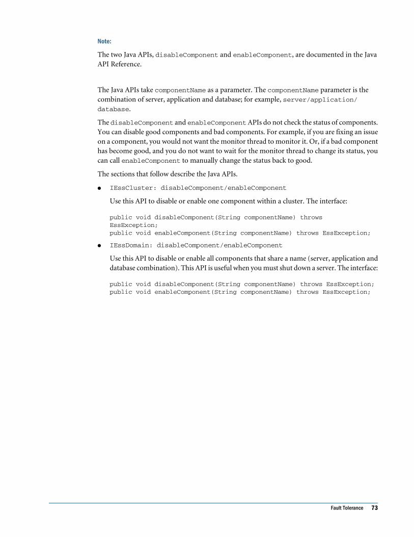
Note:
The two Java APIs, disableComponent and enableComponent, are documented in the JavaAPI Reference.
The Java APIs take componentName as a parameter. The componentName parameter is thecombination of server, application and database; for example, server/application/database.
The disableComponent and enableComponent APIs do not check the status of components.You can disable good components and bad components. For example, if you are fixing an issueon a component, you would not want the monitor thread to monitor it. Or, if a bad componenthas become good, and you do not want to wait for the monitor thread to change its status, youcan call enableComponent to manually change the status back to good.
The sections that follow describe the Java APIs.
● IEssCluster: disableComponent/enableComponent
Use this API to disable or enable one component within a cluster. The interface:
public void disableComponent(String componentName) throws EssException; public void enableComponent(String componentName) throws EssException;
● IEssDomain: disableComponent/enableComponent
Use this API to disable or enable all components that share a name (server, application anddatabase combination). This API is useful when you must shut down a server. The interface:
public void disableComponent(String componentName) throws EssException;public void enableComponent(String componentName) throws EssException;
Fault Tolerance 73

74 Administering Provider Services

9Clustering Provider Services
In This Chapter
Provider Services Clustering... . . . . . . . . . . . . . . . . . . . . . . . . . . . . . . . . . . . . . . . . . . . . . . . . . . . . . . . . . . . . . . . . . . . . . . . . . . . . . . . . . . . . . . . . . . . . . . . . . . . .75
Clustering on Tomcat .. . . . . . . . . . . . . . . . . . . . . . . . . . . . . . . . . . . . . . . . . . . . . . . . . . . . . . . . . . . . . . . . . . . . . . . . . . . . . . . . . . . . . . . . . . . . . . . . . . . . . . . . . . . . .78
Clustering on WebLogic 8.1.6 ... . . . . . . . . . . . . . . . . . . . . . . . . . . . . . . . . . . . . . . . . . . . . . . . . . . . . . . . . . . . . . . . . . . . . . . . . . . . . . . . . . . . . . . . . . . . . . . . . .81
Clustering on WebLogic 9.1... . . . . . . . . . . . . . . . . . . . . . . . . . . . . . . . . . . . . . . . . . . . . . . . . . . . . . . . . . . . . . . . . . . . . . . . . . . . . . . . . . . . . . . . . . . . . . . . . . . . .86
Clustering on WebSphere 6.0.2.11 and 6.1.0.5 ... . . . . . . . . . . . . . . . . . . . . . . . . . . . . . . . . . . . . . . . . . . . . . . . . . . . . . . . . . . . . . . . . . . . . . . . . . . . .92
Clustering on Oracle 10g Application Server .. . . . . . . . . . . . . . . . . . . . . . . . . . . . . . . . . . . . . . . . . . . . . . . . . . . . . . . . . . . . . . . . . . . . . . . . . . . . . . . . . 102
Provider Services ClusteringProvider Services is deployed through application servers, such as BEA WebLogic or IBMWebSphere, which provide clustering and load balancing. Clustering involves deployingmultiple instances of Provider Services to handle requests from Smart View, Java API, or XMLAclients.
The benefits of clustering:
● High availability
● Load balancing
● Scalability
You can create two types of clusters:
● Horizontal clusters
● Vertical clusters
Horizontal clustering deploys application server instances across multiple machines. Forsimplicity, Smart View is used for all examples.
In Figure 11, Provider 1 and Provider 2 are running on separate machines. Dispatchers, such asapplication servers, deliver Smart View client requests to Provider Services in the cluster.
Provider Services Clustering 75

Figure 11 Horizontal Clustering
Vertical clustering deploys multiple application server instances on one machine. In Figure 12,Provider 1 and Provider 2 run on the same machine.
Figure 12 Vertical Clustering
Clustered Provider Services can connect to clustered or stand-alone Essbase databases. InFigure 13, Provider 1 connects to clustered data sources A and B. Provider 2 connects to onedata source C. Provider 3 connects to clustered data sources D and E.
76 Clustering Provider Services
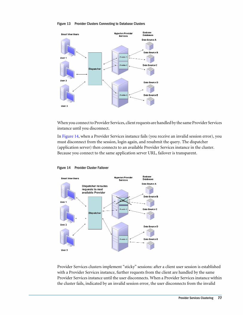
Figure 13 Provider Clusters Connecting to Database Clusters
When you connect to Provider Services, client requests are handled by the same Provider Servicesinstance until you disconnect.
In Figure 14, when a Provider Services instance fails (you receive an invalid session error), youmust disconnect from the session, login again, and resubmit the query. The dispatcher(application server) then connects to an available Provider Services instance in the cluster.Because you connect to the same application server URL, failover is transparent.
Figure 14 Provider Cluster Failover
Provider Services clusters implement “sticky” sessions: after a client user session is establishedwith a Provider Services instance, further requests from the client are handled by the sameProvider Services instance until the user disconnects. When a Provider Services instance withinthe cluster fails, indicated by an invalid session error, the user disconnects from the invalid
Provider Services Clustering 77

session and logs in again, using the same URL and user login information. A new session witha healthy Provider Services instance within the cluster is established.
The failover to the healthy Provider Services instance is transparent as the user reconnects withthe same URL (the dispatcher’s URL) that was used earlier. A dispatcher delivers the requeststo the Provider Services server instances that are part of the cluster.
The following sections contain procedures for configuring vertical and horizontal clustering forthe Web application servers.
● “Clustering on Tomcat” on page 78
● “Clustering on WebLogic 8.1.6” on page 81
● “Clustering on WebSphere 6.0.2.11 and 6.1.0.5” on page 92
Note:
You cannot use Administration Services Console to administer Provider Services clusters, onlyEssbase database clusters. Provider Services clusters must be created and administered usingapplication servers.
Note:
The dispatcher URL should not be used by the Administration Services Console to configurethe Provider Services instances as that would configure only one of the Provider instances thatare part of the cluster and not all the Provider instances in the cluster.
Clustering on TomcatAfter Provider Services is configured for clustering, you cannot use the Administration ServicesConsole to administer the individual Provider Services instances for Tomcat on the server thatis part of the cluster. These Provider Services instances use the custom protocol AJP1.3; therefore,the Provider Services configuration must be completed before the instances are configured forthe cluster.
The procedures explain how to cluster Provider Services on three Tomcat servers running ontwo machines (Machine1, Machine2) with Apache as dispatcher on Machine1. Machine1 needstwo installations of Provider Services to set up vertical clustering. Both installations on Machine1can share Hyperion_Home. Machine2 joins the cluster to set up horizontal clustering.
➤ To configure clustering on Tomcat:
1 Install Provider Services on both Machine1 and Machine2.
The default Tomcat deployments on these machines are configured for port 13080.
2 Install Provider Services again on Machine1, but in a different location.
Hyperion_Home can be the same for both installations. Because the first installation uses port13080, use the Configuration Utility tool to deploy Provider Services on Tomcat on a differentport, for example, 13081.
78 Clustering Provider Services

Provider Services now has three installations:
● Machine1 installation on port 13080 is referred to as server1.
● Machine1 installation on port 13081 is referred to as server2.
● Machine2 installation on port 13080 is referred to as server3.
3 Install Apache on Machine1.
4 Install mod_jk2.
The mod_jk2 option enables you to cluster Tomcat servers, implement load-balancing andfailover strategies, and dynamically add and remove members from the cluster. A binary buildor packaged build of mod_jk2 is available for many platforms. A packaged build is the easiestway to install mod_jk2. The binaries are available at http://jakarta.apache.org/site/downloads/downloads_tomcat.html. Extract the mod_jk2 package to APACHE_HOME onMachine1. This copies the binaries to the APACHE_HOME/modules and the configuration filesinto the APACHE_HOME/conf.
5 When deployed, you must configure Apache to load the mod_jk2 module. Edit the httpd.conf file underAPACHE_HOME/conf to add the following line:
Include conf/mod_jk2.conf
6 Edit workers2.properties in the same directory as httpd.conf in APACHE_HOME/conf toconfigure mod_jk2. Replace Machine1 and Machine2 with IP hostnames of the respective machines.
This is a workers2.properties file based on the configuration outlined in this procedure:
[shm:]info=Shared memoryfile=anonymousver=1
[channel.socket:server1]info=Ajp13 forwarding over sockethost=Machine1port=13080tomcatId=server1
[channel.socket:server2]info=Ajp13 forwarding over sockethost=Machine1port=13081tomcatId=server2
[channel.socket:server3]info=Ajp13 forwarding over sockethost=Machine2port=13080tomcatId=server3
[lb:lb]info=Load balancersticky=1ver=1 [logger]
Clustering on Tomcat 79

level=error#level=debug
[logger.file:0]info=Where to put the mod_jk2 log.file=${serverRoot}/logs/jk2.loglevel=error#level=debug
[status:status]info=Status worker, displays runtime informations
[uri:/jkstatus/*]info=The Tomcat /jkstatus handlergroup=status:status
[uri:/aps/*]info=Map Analytic Provider Services to the Web server uri spacegroup=lb:lbver=1
Entries in workers2.properties:
● The [channel.socket:] sections define the location of your Tomcat servers. The host isthe IP address of your Tomcat instances.
● The tomcatId is a name that you give that instance of Tomcat; it must match the engine'sjvmRoute entry in Tomcat server.xml, which we will set up shortly.
● The [lb:] section is the load balancer. By default, this includes the servers defined inworkers2.properties(server1 and server2 in our case).
● The sticky property ensures that when Apache has dispatched a request to a server, requestsin that session go to the same server as long as it is available.
● The tomcatId and jvmRoute entries in Tomcat server.xml make the sticky propertywork.
● The [uri:] sections define which URL patterns to forward to Tomcat.
● The group property declares which load balancer to use.
● The [status:] section and its [uri:/jkstatus/*] section are used to monitoring thecluster.
7 Edit the first Tomcat server's conf/server.xml as follows:
a. Change the <Connector> entry for the port 13080 used by Provider Services to includethe attribute protocol="AJP/1.3" similar to:
<Connector port="13080" enableLookups="false" redirectPort="8443"
debug="0" protocol-”AJP/1.3”/>
b. Edit the Engine entry to have a jvmRoute matching the tomcatId entry inworkers2.properties:
<Engine name="Catalina" defaultHost="localhost" debug="0"
jvmRoute="server1">
c. Repeat for server2, but set the engine entry to jvmRoute="server2".
80 Clustering Provider Services

d. Repeat for server3, but set the engine entry to jvmRoute="server3".
8 Start the three Tomcat and Apache servers.
9 Start Internet Explorer and enter the URL:
http://Machine1:8080/aps/APS
8080 is the default port on which the Apache server accepts requests.
The Web browser displays the message “Hyperion Provider Services,” which is served by one ofthe two Tomcat servers.
Repeatedly refreshing the URL results in the page getting invoked from the three Tomcat serversin the cluster alternatively, demonstrating a round-robin load-balancing sequence.
Clustering on WebLogic 8.1.6To cluster providers and dispatch requests, you must install WebLogic 8.1.6 on each machinethat is part of the cluster. A node manager must be running on each machine that is part of thecluster.
Procedures to cluster Provider Services on three WebLogic servers running on two Windowsmachines, Machine1 and Machine2, are provided, as are vertical and horizontal clusteringexamples. Machine1 contains the balancer Web application for dispatching requests and is usedas the cluster server to create and control the cluster.
➤ To set up clustering on WebLogic 8.1.6:
1. Deploy, configure, and start the Provider, the node manager server, and WebLogic server.
2. Create and configure the first machine.
3. Create and configure the second machine.
4. Create the cluster.
5. Create the first managed server.
6. Create the second managed server.
7. Create the third managed server.
8. Start all three managed servers.
9. Configure the WebLogic plug-in for load balancing a cluster.
➤ To deploy, configure, and start Provider Services, node manager server, and WebLogic server:
1 Use the Configuration Utility (see Chapter 3, “Configuring Provider Services ”) to deploy Provider Servicesfor WebLogic 8.1 server on both machines, and start Provider Services on both machines.
2 On the first machine, in WL_Home\common\nodemanager, edit nodemanager.hosts to add theMachine1 IP address.
Managed servers are started from Machine1.
Clustering on WebLogic 8.1.6 81

3 On the first machine, in WL_Home\server\bin, using the StartNodeManager window common script,start Node Manager Server.
4 On the second machine, in WL_Home\common\nodemanager, edit nodemanager.hosts to addthe Machine1 IP address.
Note:
If nodemanager.hosts does not exist, start and stop the node manager.
5 On the second machine, in WL_Home\server\bin, using the StartNodeManager window common script,start Node Manager Server.
The Node Manager on both machines must be running before you begin configuring the clusterserver.
6 On Machine1 at WL_Home\server\bin\StartWLS.cmd, start the WebLogic server.
Note:
This is not the server instance where Provider Services is set up. This is the default WebLogicserver.
➤ To create and configure the first machine:
1 Open the WebLogic Admin Console Web application at
http://Machine1:7001/console
2 In the Navigation tree, select the Machines node.
3 Click Configure a new machine.
4 In General, enter the machine 1 name as Machine1, and click Create.
5 Select Node Manager.
6 In Listen Address, enter the Machine1 IP address.
7 In Listen Port, enter the default, 5555.
8 Click Apply, and exit.
9 Click Monitoring and verify that the Node Manager Status is RUNNING.
➤ To create and configure the second machine:
1 In the WebLogic Admin Console Web application on Machine1, in the Navigation tree, select Machines.
2 Click Configure a new Machine.
3 In General, enter the machine 2 name as Machine2, and click Create.
4 Select Node Manager.
5 In Listen Address, enter the Machine2 IP address.
6 In Listen Port, enter the default, 5555.
7 Click Apply, and exit.
82 Clustering Provider Services

8 Click Monitoring and verify that the Node Manager Status is RUNNING.
After creating and configuring both machines, subnodes Machine1 and Machine2 are listedunder the Machines node.
➤ To create the cluster:
1 In the WebLogic Admin Console Web application on Machine1, in the Navigation tree, select Clusters.
2 Click Configure a new Cluster.
3 In General, enter the cluster name as SmartViewCluster.
4 In Cluster Address, enter the IP address or server name of Machine1 and Machine2, separated by a comma;for example:
Machine1:13080,Machine1:13081,Machine2:13080
5 Select Default Load Algorithm as round robin.
6 Click Apply to create the cluster.
7 In Cluster, select MultiCast.
8 Type the Multicast Address (the default is 237.0.0.1 and port number is 7001).
➤ To create the first managed server:
1 In the navigation tree, select Servers.
2 Click Configure a New Server.
3 In General, enter the Name Server1.
4 From Machine, select Machine1.
5 From Cluster, select SmartViewCluster.
6 In Listen Address, enter the IP address of Machine1.
7 Enter the Listen Port for Machine1 as 7005, and click Create.
8 Select Protocols and click Channels.
9 Click Configure a New Network Channel for Server1 on Machine1.
10 Enter the name of the New Network Channel (for example, Network Channel1), and click Create.
11 Select Configuration > Remote Start. In Arguments, input the parameter:
-DESS_ES_HOME=%APS_HOME%
Replace %APS_HOME% with the install location of the first instance of Provider Services onMachine1.
➤ To create the second managed server:
1 In the navigation tree, select Servers.
2 Click Configure a New Server.
3 In General, enter the Name Server2.
Clustering on WebLogic 8.1.6 83

4 From Machine, select Machine1.
5 From Cluster, select SmartViewCluster.
6 In Listen Address, enter the IP Address of Machine1.
7 In Listen Port of Machine1 enter 7006, and click Create.
8 Select Protocols and click Channels.
9 Click Configure a New Network Channel for Server2 on Machine1.
10 Enter the name of the New Network Channel (for example, Network Channel2), and click Create.
11 Select Configuration > Remote Start. In Arguments, input the parameter:
-DESS_ES_HOME=%APS_HOME%
Replace %APS_HOME% with the install location of the second instance of Provider Serviceson Machine1.
➤ To create the third managed server:
1 In the navigation tree, select Servers.
2 Click Configure a New Server.
3 In General, enter the Name as Server3.
4 From Machine, select Machine2.
5 From Cluster, select SmartViewCluster.
6 In Listen Address, enter the Machine2 IP address.
7 In Listen Port of Machine2, enter 7005, and click Create.
8 Select Protocols > Channels.
9 Click Configure a New Network Channel for Server3 on Machine2.
10 Enter the name of the New Network Channel (for example, Network Channel3), and click Create.
11 Select Configuration > Remote Start. In Arguments, input the parameter:
-DESS_ES_HOME=%APS_HOME%
Replace %APS_HOME% with the install location of Provider Services on Machine2.
➤ To deploy the Provider Services Web application and start all three managed servers:
1 In the left pane, select Deployments.
2 Select Web Applications > Deploy a new Web Application Module > Upload your file(s).
3 On the Upload and Install an Application or Module page, select Browse to navigate to %APS_HOME%\AppServer\InstallableApps\Common\aps.war. Select aps.war and click Upload.
4 Select the option button for aps.war and click Target Module.
5 Under Select targets for this Web application module, select All servers in the cluster and APSCluster, and click Continue.
84 Clustering Provider Services

6 On the Review your choices and deploy page, verify that Copy this Web Application module onto everytarget for me is selected and that the Identity Name is aps. Click Deploy.
7 In the left pane, select Clusters.
8 Select APSCluster > Start all Managed Servers
9 In the right pane, select Start this server.
10 In the confirmation message window, click Yes.
First, the server displays the state as STARTING and the status as TASK IN PROGRESS.
After the server is started, the state is RUNNING and the status is TASK COMPLETED.
11 After the server is started, to reconfirm the state of all servers as RUNNING, click the servers in the navigationtree.
Configuring the WebLogic Load Balancing Plug-inWebLogic provides a plug-in for load balancing a cluster. This procedure details the plug-inconfiguration for Apache 2. You must download and install Apache 2 from the Jakarta Web site,http://jakarta.apache.org.
➤ To configure the plug-in for Apache 2:
1 Copy mod_wl_20.so in WL_HOME/weblogic81/server/bin module to APACHE_HOME/modules.
2 Edit APACHE_HOME/conf/httpd.conf to include the following lines.
Include the cluster created in the previous steps to be load balanced by the Web server. Rememberto replace Machine1 and Machine2 with their corresponding IP addresses.
LoadModule weblogic_module modules/mod_wl_20.so<IfModule mod_weblogic.c>WebLogicCluster Machine1:13080,Machine1:13081,Machine2:13080MatchExpression /aps</IfModule>
3 Start the Apache server.
4 Test the setup using the URL:
http://Machine1:8080/aps/APS
The default port for Apache is 8080.
Repeatedly refreshing the URL results in the Provider Services version details page beingdisplayed alternatively from each of the cluster servers, demonstrating the round-robin loadbalance sequence.
Clustering on WebLogic 8.1.6 85

Clustering on WebLogic 9.1For clustering and dispatcher features in WebLogic, install WebLogic 9.1 on the machines thatwill be part of the cluster. WebLogic requires that a node manager be running on the machinefor each machine that is part of the cluster.
Following is the sequence in which to cluster the Provider Services on three WebLogic serversrunning on two Windows machines (Machine1, Machine2). We also use Machine1 as theAdministration Server to create and control the cluster.
Install Provider Services twice on Machine2 to demonstrate vertical clustering. Both providerinstances can, however, share the same HYPERION_HOME. For example purposes, assume thefollowing installation locations:
Table 11
Machine Installation Location
Machine1 D:\Hyperion\APS
Machine2 E:\Hyperion\APS
Machine2 E:\Hyperion\APS-Dup
➤ To configure clustering and dispatching in WebLogic
1 Using the Hyperion Configuration Utility, configure one instance of Provider Services on Machine1 andconfigure one instance of Provider Services on Machine2. Do not configure the second instance of ProviderServices (APS-Dup) on Machine2. Ensure that the WebLogic domain name used is the same on bothmachines.
Table 12
Component Server Name Port Domain
Machine1 Provider Services server1 13080 aps
Machine2 Provider Services server2 13080 aps
2 On Machine1, in WL_Home server\bin, using the StartNodeManager Windows command script(runs by default on port 5556), start Node Manager Server.
3 On Machine2, in WL_Home server\bin, using StartNodeManager Windows command script (runsby default on port 5556), Start Node Manager Server.
Before you configure the cluster server, both Node Managers should be running.
4 On Machine1, start the WebLogic server.
This is the default WebLogic Admin server (by default running on port 7001), not the serverinstance where Provider Services is set up.
5 Using a browser, log in to the WebLogic Admin console at:
http://Machine1:7001/console
86 Clustering Provider Services

Note:
The default user name and password are both hyperion.
6 In the left pane, under Domain Structure, select Environment.
a. Under Change Center, click Lock & Edit.
b. Under Environment, click Machines.
c. On the Summary of Machines page, click New.
d. On the Create a New Machine page, enter the Name as Machine1 and click OK.
e. On the Summary of Machines page, click Machine1.
f. On the Settings for Machine1 page, select Configuration > Node Manager.
g. In Listen Address, enter the Machine1 host name and click Save.
h. Under Monitoring, verify that the status for this node manager is Reachable.
i. Under Environment, click Machines to begin setting up Machine2.
j. On the Summary of Machines page, click New.
k. On the Create a New Machine page, enter the Name as Machine2 and click OK.
l. On the Summary of Machines page, click Machine2.
m. On the Settings for Machine2 page, select Configuration > Node Manager.
n. In Listen Address, enter the Machine2 host name and click Save.
o. Under Monitoring, verify that the status for this node manager is Reachable.
p. Under Change Center, click Activate Changes.
7 In the left pane, under Domain Structure, select Environment > Clusters.
a. Under Change Center, click Lock & Edit.
b. On the Summary of Clusters page, click New.
c. On the Create a New Cluster page, enter the Name as APSCluster and click OK.
d. On the Summary of Clusters page, click APSCluster.
e. In Cluster Address, enter the host name for Machine1 and Machine2, separated by acomma; for example:
Machine1,Machine2.
f. In Number of Servers in Cluster Address, enter 3 and click Save.
g. Under Change Center, click Activate Changes.
8 In the left pane, under Domain Structure, select Environment > Servers.
a. Under Change Center, click Lock & Edit.
b. On the Summary of Servers page, click New.
c. On the Create a New Server page:
● In Server Name, enter Server1.
● In Server Listen Address, enter the Machine1 host name.
Clustering on WebLogic 9.1 87

● In Server Listen Port, enter 13080.
● Select Yes, make this server a member of an existing cluster.
● From Select a Cluster, select APSCluster.
● Click Next.
d. On the Review Choices page, verify the details and click Finish.
e. On the Summary of Servers page, select Server1.
f. On the Settings for Server1 page, select Configuration > General > Machine >Machine1. Click Save.
g. Select Protocols > Channels, and click New.
h. On the Create a New Network Channel page:
● In Name, enter Channel1.
● In Protocol, enter t3.
● Click Next.
● On the next Network Channel Addressing page, click Finish.
i. On the Settings for Server1 page, select Configuration > Server Start:
● In Root Directory, enter
D:/Hyperion/APS/AppServer/InstalledApps/WebLogic/9.1/aps
● In Arguments, enter
-DESS_ES_HOME= D:\Hyperion\APS
● Click Save.
j. Click Activate Changes under Change Center.
9 For Server2, in the left pane, under Domain Structure, select Environment > Servers.
a. Under Change Center, click Lock & Edit.
b. On the Summary of Servers page, click New.
c. On the Create a New Server page:
● In Server Name, enter Server2.
● In Server Listen Address, enter the Machine2 host name
● In Server Listen Port, enter 13080.
● Select Yes, make this server a member of an existing cluster
● From Select a Cluster, select APSCluster.
● Click Next.
d. On the Review Choices page, verify details and click Finish.
e. Select Server2 on the Summary of Servers page.
f. On the Settings for Server2 page, select Configuration > General > Machine >Machine2. Click Save.
88 Clustering Provider Services

g. Select Protocols > Channels. Click New.
h. On the Create a New Network Channel page:
● In Name, enter Channel2.
● In Protocol, enter t3.
● Click Next.
● On the next Network Channel Addressing page, click Finish.
i. On the Settings for Server2 page, select Configuration > Server Start:
● In Root Directory, enter
E:/Hyperion/APS/AppServer/InstalledApps/WebLogic/9.1/aps
● In Arguments, enter
-DESS_ES_HOME= E:\Hyperion\APS
● Click Save.
j. Under Change Center, click Activate Changes.
10 For vertical cluster component, Server3, in the left pane, under Domain Structure, select Environment >Servers.
a. Under Change Center, click Lock & Edit.
b. On the Summary of Servers page, click New.
c. On the Create a New Server page:
● In Server Name, enter Server3.
● In Server Listen Address, enter the Machine2 host name.
● In Server Listen Port, enter 13081.
● Select Yes, make this server a member of an existing cluster.
● From Select a Cluster, select APSCluster.
● Click Next.
d. On the Review Choices page, verify the details and click Finish.
e. On the Summary of Servers page, select Server3.
f. On the Settings for Server3 page, select Configuration > General > Machine >Machine2. Click Save.
g. Select Protocols > Channels , and click New.
h. On the Create a New Network Channel page:
● In Name, enter Channel3.
● In Protocol, enter t3.
● Click Next.
● On the next Network Channel Addressing page, click Finish.
i. On the Settings for Server3 page, select Configuration > Server Start:
Clustering on WebLogic 9.1 89

● In Root Directory, enter
E:/Hyperion/APS/AppServer/InstalledApps/WebLogic/9.1/aps
● In Arguments, enter
-DESS_ES_HOME= E:\Hyperion\APS-Dup
● Click Save.
Note:
While the Root Directory points to the first Provider Services installation location, theESS_ES_HOME parameter should point to the second Provider Services installationlocation.
j. Under Change Center, click Activate Changes.
11 Deploy Provider Services to all cluster servers:
a. In the left pane, in Domain Structure, select Deployments.
b. Under Change Center, click Lock & Edit
c. On the Summary of Deployments page, click the aps application deployed in step 6.
d. On the Settings for aps page, select Targets.
e. Under Clusters, select APSCluster and All servers in the cluster. Click Save
f. Under Change Center, click Activate Changes.
12 To enroll the Node Managers, on Machine2, start a command prompt and run the Windows command scriptat WL_HOME/server/bin/setWLSEnv.cmd.
a. Start the WebLogic Scripting Tool (WLST) using the following Java command at theprompt:
java -Dweblogic.security.TrustKeyStore=DemoTrust -
Dweblogic.security.SSL.ignoreHostnameVerification=false -
Dweblogic.ReverseDNSAllowed=false weblogic.WLST
b. Connect to the WebLogic Admin server on Machine1 using the following command atthe prompt:
connect ('username','password','t3://Machine1:adminport’)
Specify the user name and password that were used to log in the WebLogic Admin server.
c. Download the Node Manager properties using the following command at the prompt:
nmEnroll ('E:/Hyperion/APS/AppServer/InstalledApps/WebLogic/9.1/
aps')
Note:
The location specified here on Machine2 is the one that was configured using the HyperionHyperion Configuration Utility, and not the second instance.
d. Exit from WLST using the exit command:
90 Clustering Provider Services
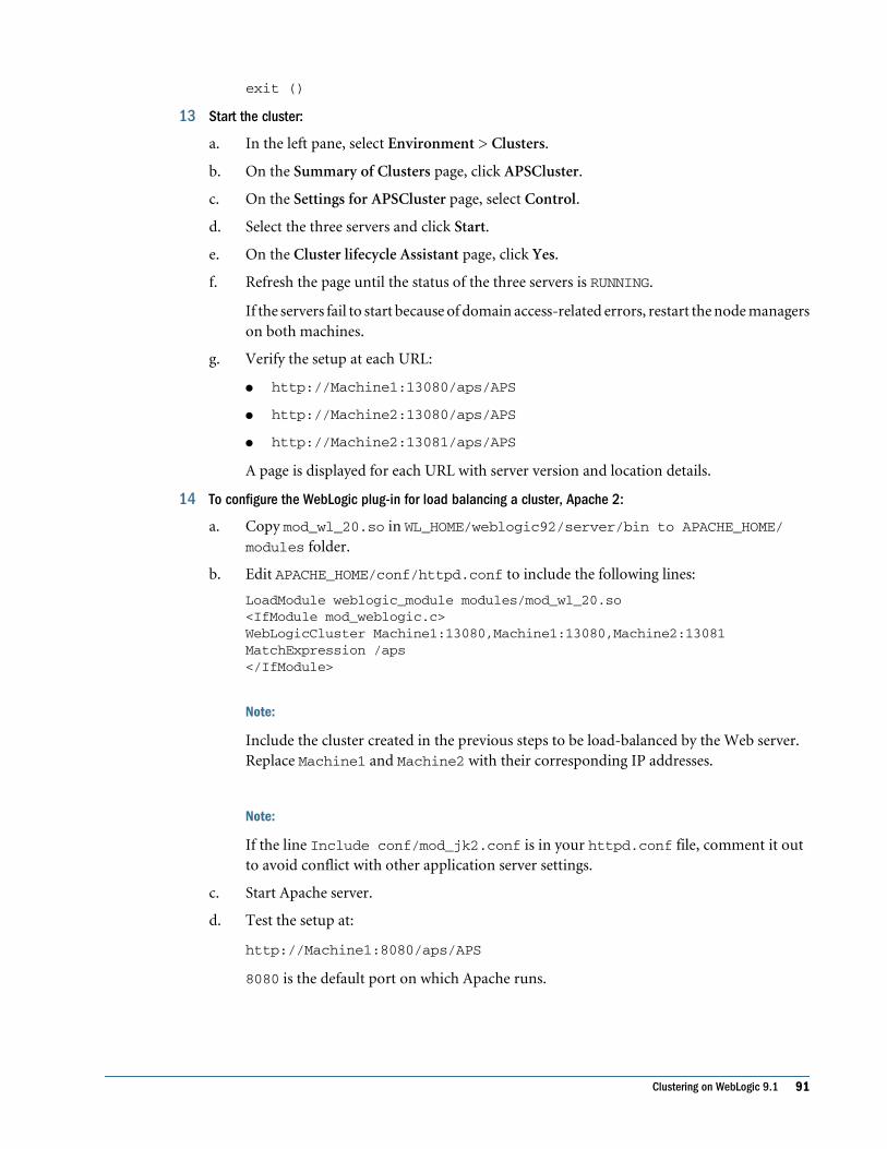
exit ()
13 Start the cluster:
a. In the left pane, select Environment > Clusters.
b. On the Summary of Clusters page, click APSCluster.
c. On the Settings for APSCluster page, select Control.
d. Select the three servers and click Start.
e. On the Cluster lifecycle Assistant page, click Yes.
f. Refresh the page until the status of the three servers is RUNNING.
If the servers fail to start because of domain access-related errors, restart the node managerson both machines.
g. Verify the setup at each URL:
● http://Machine1:13080/aps/APS
● http://Machine2:13080/aps/APS
● http://Machine2:13081/aps/APS
A page is displayed for each URL with server version and location details.
14 To configure the WebLogic plug-in for load balancing a cluster, Apache 2:
a. Copy mod_wl_20.so in WL_HOME/weblogic92/server/bin to APACHE_HOME/modules folder.
b. Edit APACHE_HOME/conf/httpd.conf to include the following lines:
LoadModule weblogic_module modules/mod_wl_20.so <IfModule mod_weblogic.c>WebLogicCluster Machine1:13080,Machine1:13080,Machine2:13081MatchExpression /aps</IfModule>
Note:
Include the cluster created in the previous steps to be load-balanced by the Web server.Replace Machine1 and Machine2 with their corresponding IP addresses.
Note:
If the line Include conf/mod_jk2.conf is in your httpd.conf file, comment it outto avoid conflict with other application server settings.
c. Start Apache server.
d. Test the setup at:
http://Machine1:8080/aps/APS
8080 is the default port on which Apache runs.
Clustering on WebLogic 9.1 91

Repeatedly refreshing the URL results in the Provider Services version details page beingdisplayed alternatively from each cluster server, demonstrating the round-robin load-balancing sequence.
Clustering on WebSphere 6.0.2.11 and 6.1.0.5To set up a clustering environment on WebSphere, you must install these products:
● IBM WebSphere Application Server Base 6.0.x
The Base installation bundles the IBM HTTP Server 6.0 and the Web Server Plugins.
● IBM WebSphere Application Server Network Deployment 6.0.x
Vertical Clustering Setup Sequence
➤ To set up vertical clustering (multiple instances of Provider Services on a machine):
1 Install and start IBM WebSphere.
2 Add nodes and create clusters.
3 Set up cluster members for Provider Services deployment.
4 Deploy Provider Services to the cluster.
5 Verify Provider Services on the cluster.
6 Install the IBM HTTP Server 6.0, and install Web Server Plug-in.
7 Configure IBM HTTP server as a dispatcher using the Plug-in.
8 Start IBM HTTP server.
PrerequisitesInstall Provider Services on each machine on which your application server base is installed. Forexample, in a Horizontal clustering environment, Provider Services must be installed on eachof the nodes (that is, machines) that will have the Base installed to host this provider servicesWeb application.
Clustering Setup
➤ To install and start WebSphere 6.x:
1 Install IBM WebSphere Application Server Base v6.x.
For custom installation, the minimum configuration:
● Application Server
● Administration
92 Clustering Provider Services

● IBM HTTP Server
● Web Server Plug-ins > IBM HTTP Server
If you are configuring horizontal clustering, run Provider Services on multiple nodes (machines).WebSphere Application Server Base is required on each node.
2 Install IBM WebSphere Network Deployment v6.x.
● Because providers are configured on the same machine in vertical clustering, the installerdetects an Application Server and prompts you:
❍ Install a new copy of V6 Application Server product.
❍ Add features to an existing copy of V6 Application Server product.
Choose “Install a new copy of V6 Application Server product.”
Also, specify a different directory location for Network Deployment. Do not choose the<WAS_ROOT_DIR>\WebSphere\AppServer directory; it will override your Baseinstallation from step 2. For example, specify <WAS_ROOT_DIR>\WebSphere\ND.
● If setting up horizontal clustering, you may install the Network Deployment on a differentserver or machine.
● During installation, when you see the Profile Type selection screen, choose “Create adeployment manager profile”.
● With vertical Clustering, the port values for Deployment Manager will be assignedautomatically so that it does not conflict with that of Base.
3 After successful installation of WebSphere Application Server Base (step 1), start WebSphere ApplicationServer at:
WebSphere_Home\AppServer\bin\StartServer Server1
4 After successful installation of the Network Deployment product (step 1), start Deployment Manager at:
WebSphere_Home\DeploymentManager\bin\StartServer dmgr
5 Connect to the Admin console of Network Deployment and log in as admin at:
http://<ND_HostName>:<ND_Port>/ibm/console
For example, if Deployment Manager is assigned port 9061, the URL of Network DeploymentAdmin Console is http://<hostname>:9061/ibm/console, where <hostname> is themachine name where you have installed your Network Deployment product.
➤ To add nodes:
1 Select System Administration > Nodes and click Add Node.
a. Choose Managed node and click Next.
b. Specify the Host Name (or IP address) where your WAS-Base Server is installed.
c. Choose JMX Connector Type as SOAP; by default, the port is 8880.
d. Click OK.
Clustering on WebSphere 6.0.2.11 and 6.1.0.5 93

e. If your WAS-Base is on Windows, the Add Managed Windows Node is displayed, you canselect this node agent to run as Windows Service. Leave this option unselected and clickOK.
After the node is successfully added, the new node will not be available in the console untilyou log in again.
2 Log out and log in again to the Network Deployment console.
3 Repeat these steps to add the nodes you require to host the Application Servers.
Note:
After you have migrated the Base Server instance to Node, you must start the node if you stopit or if you restart that machine. You can do this by running the <WAS_HOME>/bin/startNodescript (for example, C:\WebSphere\AppServer\bin\startNode.bat). To stop the node, you canrun the <WAS_HOME>/bin/stopNode script.
Additional steps (workaround) for known WebSphere 6 deployment scenario issue, WAS-Baseand WAS-ND installed on the same machine:
This can occur in the case of a vertical clustering, or even a horizontal clustering, where one ofthe nodes is the same machine where you installed WAS-ND.
➤ If this is your scenario, before you create a cluster, perform these steps.
1 Select Servers > Application Servers and select New to start creating a dummy server.
2 In Step 1 Select a Node, choose the node where both WAS-Base and WAS-ND are running, name the server(for example, “dummyServer”), and click Next.
3 In Step 2 Select a server template, choose the server template where WAS-Base and WAS-ND are running,name the server (for example, “dummyServer),” and click Next.
4 In Step 3 Specify server specific properties, choose the server where WAS-Base and WAS-ND are running,name the server (for example, “dummyServer”), and click Next.
5 In Step 4 Confirm new server, click Finish.
Notes:
The technical reason for this step is in WAS ND 6.0.1. The first application server created isassigned a DCS_UNICAST_ADDRESS port that conflicts with the Deployment Manager port.By performing the above steps, the dummy server is assigned that port, after which we can createthe cluster and application server instances under it, and then delete the dummy server.
Doing the above is one solution. Another is to assign ports or change ports manually, whichrequires tracking the ports on each application server instance to avoid conflicts. For moreinformation, refer to WebSphere Application Server v6 System Management & ConfigurationHandbook at http://www.redbooks.ibm.com/.
➤ To create clusters:
1 Select Servers > Clusters and click New to start creating a Hyperion Provider Server.
94 Clustering Provider Services

2 In Step 1 Create New Cluster, name the Hyperion Provider Server (for example, APSCluster) and clickNext.
3 In Step 2 Create Cluster Members, add the WebSphere application servers under the new cluster.
a. Specify a unique name for this cluster member (for example, APSClone1).
b. Select the node where you want this application server to be hosted, selecting a node thatyou added in step 1 or step 3 in the procedure for adding nodes above).
c. Use the default values for the remaining input items on the page, and click Apply.
d. Optional: To add more cluster members, repeat step 3.a–step 3.d.
e. After you are done adding cluster members, click Next.
f. In Step 3 Summary, click Finish.
Additional steps (workaround) for known WebSphere 6 deployment scenario issue, WAS-Baseand WAS-ND installed on the same machine:
If you created a dummy server for this scenario, delete that server now.
➤ To delete the dummy server:
1 Select Servers > Application Servers, select the dummy server, and click Delete.
2 Click OK to complete the deletion and save your configuration.
➤ To set up cluster members for the Provider Services deployment:
1 Create a virtual host for the Provider Services cluster.
a. Select Environment > Virtual Hosts.
b. Create a new Virtual Host for Provider Services (for example, APSHost).
c. Click Save.
2 Apply Provider Services Virtual Host to cluster members:
a. Select Servers > Application Servers.
b. Select an application server in your Provider cluster (for example, APSClone1).
c. On this application server (APSClone1) page, select Web Container Settings > WebContainer.
d. On Web Container, change Default virtual host to your Provider Services Virtual Host(for example, APSHost). Click Apply.
e. Return to the application server page. Expand Ports to note the HTTPand HTTPS portsfor this server instance (for example, 9081 and 9444, respectively).
HTTP Port is indicated by WC_defaulthost; HTTPS Port byWC_defaulthost_secure.
f. Click Save.
g. Repeat step 2.a–step 2.f for all other cluster application servers.
3 Add the HTTP transports of each cluster member to Provider Virtual Host.
Clustering on WebSphere 6.0.2.11 and 6.1.0.5 95
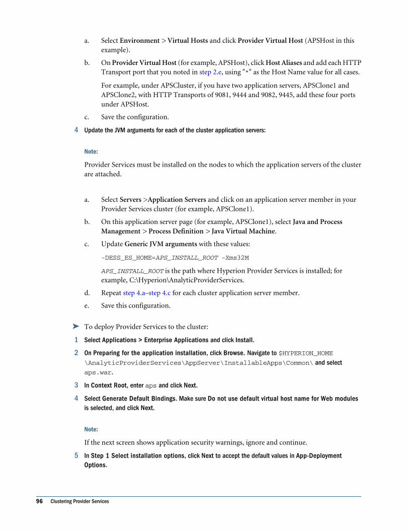
a. Select Environment > Virtual Hosts and click Provider Virtual Host (APSHost in thisexample).
b. On Provider Virtual Host (for example, APSHost), click Host Aliases and add each HTTPTransport port that you noted in step 2.e, using "*" as the Host Name value for all cases.
For example, under APSCluster, if you have two application servers, APSClone1 andAPSClone2, with HTTP Transports of 9081, 9444 and 9082, 9445, add these four portsunder APSHost.
c. Save the configuration.
4 Update the JVM arguments for each of the cluster application servers:
Note:
Provider Services must be installed on the nodes to which the application servers of the clusterare attached.
a. Select Servers >Application Servers and click on an application server member in yourProvider Services cluster (for example, APSClone1).
b. On this application server page (for example, APSClone1), select Java and ProcessManagement > Process Definition > Java Virtual Machine.
c. Update Generic JVM arguments with these values:
-DESS_ES_HOME=APS_INSTALL_ROOT –Xms32M
APS_INSTALL_ROOT is the path where Hyperion Provider Services is installed; forexample, C:\Hyperion\AnalyticProviderServices.
d. Repeat step 4.a–step 4.c for each cluster application server member.
e. Save this configuration.
➤ To deploy Provider Services to the cluster:
1 Select Applications > Enterprise Applications and click Install.
2 On Preparing for the application installation, click Browse. Navigate to $HYPERION_HOME\AnalyticProviderServices\AppServer\InstallableApps\Common\ and selectaps.war.
3 In Context Root, enter aps and click Next.
4 Select Generate Default Bindings. Make sure Do not use default virtual host name for Web modulesis selected, and click Next.
Note:
If the next screen shows application security warnings, ignore and continue.
5 In Step 1 Select installation options, click Next to accept the default values in App-DeploymentOptions.
96 Clustering Provider Services

6 In Step 2 Map modules to application servers, select the Provider Services cluster (for example,APSCluster) and check APSWebModule to indicate that aps.war is the module to map to the WebSphereserver. Click Apply. Click Next.
7 In Step 3 Map virtual hosts for web modules, select the Provider Virtual Host (for example, APSHost) andclick Next.
8 Click Next.
9 In Step 4 Summary, click Finish to start the installation.
A message prompts you that the aps_war application is successfully installed.
10 Click Save.
➤ To verify Provider Services on the cluster:
1 Select Servers > Clusters.
2 Select the cluster on which you deployed the Provider Services and click Ripplestart.
This starts the cluster, its associated application servers, and the Hyperion Provider Servicesapplication.
Note:
This process may take a few minutes, depending on your clustering environment. After thecluster is fully started, click the Status Refresh link on this page, or verify that the aps.war statusunder Applications > Enterprise Applications is Started.
3 Verify that you have successfully deployed Provider Services by inputting the Provider Services URL into abrowser.
For example, with two clone instances, APSClone1 and APSClone2, running HTTP ports 9082and 9083 respectively, the Provider Services URLs to be verified are http://hostname:9082/aps/APS and http://hostname:9083/aps/APS, respectively.
Note:
You can verify the WebSphere Application Server by directly accessing application URLs. Youcan immediately identify problems as resulting from the WebSphere configuration, not fromthe Web server or Web server plug-in. By requesting the URLs of an application through theembedded HTTP transport, you can verify an application before you configure a Web serverplug-in to support the application.
Using a Web Server as a DispatcherWebSphere Application Server provides Web server plug-ins that work with a Web server (Inthis case, IBM HTTP Server.) to route requests from the Web server to the application server.A Web server plug-in is specific to the type of Web server. It is installed on the Web servermachine and configured in the Web server configuration.
A plug-in configuration file generated on the application server and placed on the Web serveris used for routing information. The plug-in configuration file is generated using WebSphere
Clustering on WebSphere 6.0.2.11 and 6.1.0.5 97

administrative tools. Each time you make a change in the WebSphere Application Serverconfiguration that would affect how a Web server routes requests to the application server, youmust regenerate and propagate—manually or automatically—the plug-in configuration file tothe Web server.
Web servers in a distributed server environment can be local to the application server or remote.Instructions for both are below. You can use them according to your clustering setup.
➤ To install and configure IBM HTTP Server for Request Routing:
1 Install IBM HTTP Server V6.
IBM HTTP Server is available with the WebSphere Application Server V6 Base installer menu.Install this on the machine that suits your clustering setup.
Notes:
● During installation, if you chose the Typical installation, the default HTTP Server Port andHTTP Administration Port would be 80 and 8008 respectively. If some other application isrunning on port 80, and you would like to change the HTTP Server Port, choose Custominstallation and specify a different port number.
● If installing on the Windows platform, use the default options itself for running IBM HTTPServer and Administration Server as Windows Service.
2 Install the WebServer Plug-in for IBM HTTP Server V6.
The Web server plug-in and the Web server must be installed on the same machine. Dependingon your clustering environment, there could be two different clustering scenarios, HorizontalClustering or Vertical Clustering.
a. Horizontal Clustering Setup: In a distributed environment, Deployment Manager (thatis, the network deployment server) and the Web Server are on separate machines, MachineA and Machine B.
In this scenario, install the Web server plug-in on Machine B; the Deployment Manageris on Machine A.
i. Select Remote installation.
ii. In the Web Server and plug-in association screen, select <IHS_HOME>/conf/httpd.conf and specify your IBM HTTP Server port.
iii. Enter a name for the Web server definition.
For example, enter apswebserver; the default is webserver1.
iv. Select the location for the plug-in configuration file.
By default, the file is in the config directory in the plug-in install directory. Usingthe apswebserver name in the example in the previous step, the default locationfor the plug-in file:
<plugin_home>/config/apswebserver/plugin-cfg.xml
v. Specify the host name or IP address of the computer on which Deployment Manageris running (Machine A).
98 Clustering Provider Services
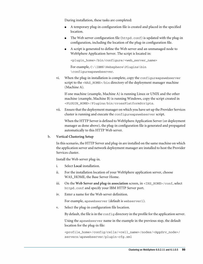
During installation, these tasks are completed:
● A temporary plug-in configuration file is created and placed in the specifiedlocation.
● The Web server configuration file (httpd.conf) is updated with the plug-inconfiguration, including the location of the plug-in configuration file.
● A script is generated to define the Web server and an unmanaged node toWebSphere Application Server. The script is located in:
<plugin_home>/bin/configure/<web_server_name>
For example, C:\IBM6\Websphere\Plugins\bin\configureapswebserver.
vi. When the plug-in installation is complete, copy the configureapswebserverscript to the <WAS_HOME>/bin directory of the deployment manager machine(Machine A).
If one machine (example, Machine A) is running Linux or UNIX and the othermachine (example, Machine B) is running Windows, copy the script created in<PLUGIN_HOME>/Plugins/bin/crossPlatformScripts.
vii. Ensure that the deployment manager on which you have set up the Provider Servicescluster is running and execute the configureapswebserver script.
When the HTTP Server is defined to WebSphere Application Server (or deploymentmanager as done above), the plug-in configuration file is generated and propagatedautomatically to this HTTP Web server.
b. Vertical Clustering Setup
In this scenario, the HTTP Server and plug-in are installed on the same machine on whichthe application server and network deployment manager are installed to host the ProviderServices cluster.
Install the Web server plug-in.
i. Select Local installation.
ii. For the installation location of your WebSphere application server, chooseWAS_HOME, the Base Server Home.
iii. On the Web Server and plug-in association screen, in <IHS_HOME>/conf, selecthttpd.conf and specify your IBM HTTP Server port.
iv. Enter a name for the Web server definition.
For example, apswebserver (default is webserver1).
v. Select the plug-in configuration file location.
By default, the file is in the config directory in the profile for the application server.
Using the apswebserver name in the example in the previous step, the defaultlocation for the plug-in file:
<profile_home>/config/cells/<cell_name>/nodes/<AppSrv_node>/
servers/apswebserver/plugin-cfg.xml
Clustering on WebSphere 6.0.2.11 and 6.1.0.5 99

During installation, the following tasks are completed:
● The plug-in configuration file is created and placed in the specified location.
● The Web server configuration file (httpd.conf) is updated with the plug-inconfiguration, including the plug-in configuration file location.
● A script is generated to define the HTTP Server and an unmanaged node toWebSphere Application Server. The script is in:
<plug-in_home>/bin/configureapswebserver
vi. When the plug-in installation is complete, ensure that the Deployment Manager onwhich you have set up the Provider Services cluster is running, and execute theconfigureapswebserver script.
The deployment manager configuration is updated, and the plug-in configurationfile is generated and propagated automatically.
3 Log out of the Network Deployment Admin console.
Because of the new installation and configuration of HTTP Server in the previous steps,administration data must be updated. If you are logged in to a session, log out without makingor saving any changes.
Notes:
● You also can configure and administer the HTTP Server to route requests throughWebSphere Admin Console.
● For other scenarios and details on how to manage Web Servers, refer to WebSphereApplication Server V6 System Management & Configuration Handbook at http://www.redbooks.ibm.com/.
➤ To add the IBM HTTP Server HTTP port to the cluster’s Virtual Host:
1 Log in to WebSphere Network Deployment console.
2 Select Servers > Web Servers and note that the HTTP Web server (for example, apswebserver) that youconfigured in the previous procedure is listed.
3 Click on the HTTP Web server you configured and note the port on which this Web server runs.
4 Select Environment > Virtual Hosts and click Provider Services Virtual Host (that is, APSHost).
5 On the Provider Services Virtual Host page (the APSHost page), click Host Aliases and add the HTTP portof the HTTP Server, which you identified in the previous step.
Use “*” as the Host Name value; for example, if you are adding a host alias with port 80, use“80”.
6 Save this configuration.
➤ Restart your Provider Services Cluster:
1 Select Servers > Clusters and select the Provider Services cluster (for example, APSCluster),
2 Click Stop and wait a few minutes so that the cluster and its application server members are stopped.
100 Clustering Provider Services

3 Select the Provider Services cluster again, click Ripplestart, and wait until the cluster is fully started.
This process may take a few minutes, depending on your clustering environment. When thecluster is completely started, click the Status Refresh link on this page to verify that the clusteris fully started. Also, under Applications > Enterprise Applications, verify that the aps.warstatus is fully started.
Starting the HTTP ServerNext, start the HTTP Server next on Windows (including as a Windows service), or on UNIX.
➤ On Windows: To start the HTTP Server, enter the following at a command prompt:
cd <IHS_HOME>apache
The Apache process can be stopped by pressing Ctrl-C.
➤ As a Windows service: To start the HTTP Server and its Admin Server, verify that these Windowsservices are listed:
● IBM HTTP Administration 6.0
● IBM HTTP Server 6.0
If they are not running from the Services window, you can start them by selecting the following:
● Start > Programs > IBM HTTP Server 6.0 > Start HTTP Server
● Start > Programs > IBM HTTP Server 6.0 > Start Administration Server
➤ On UNIX: Log in to your UNIX machine as a user having access and privileges to execute IBMHTTP Server commands, and issue the following commands:
# cd <IHS_HOME>/bin# ./apachectl stop# ./ apachectl start
Now, verify that you have successfully set up the Provider Services application through the HTTPServer.
➤ To verify that the Provider Services application is successfully set up through the HTTP Server,use the following syntax to access the Provider Services URL:
http://<IHS_HOST>:<IHS_PORT>/aps/APS
<IHS_HOST> is the host name; <IHS_PORT> is the HTTP port where your HTTP Server isrunning.
For example:
http://xyz:80/aps/APS
Clustering on WebSphere 6.0.2.11 and 6.1.0.5 101

Clustering on Oracle 10g Application ServerYou can use Oracle 10g Application Server Control Console to set up clusters.
➤ To cluster on Oracle 10g:
1 Create a DCM-managed Oracle Application Server cluster using a file-based repository as follows:
a. From the Application Server Control for the instance that you want to use as the repositoryhost, select Infrastructure (If a repository is not yet configured, Not Configured isdisplayed in the Farm Repository field.)
b. On the Infrastructure page, in the OracleAS Farm Repository Management section, clickConfigure to start the Configure Oracle Application Server Farm Repository wizard. Thehost name is displayed under Configure Oracle Farm Repository Source.
c. Click New file-based repository and select Next.
d. On the Validation page, click Finish. The Oracle Application Server File-based Farm iscreated.
2 Add standalone application server instances to the Oracle Application Server file-based Farm as follows:
a. Obtain the Repository ID for the OracleAS Server file-based Farm that you want to join.To find the Repository ID, on any OracleAS instance that uses the OracleAS file-basedFarm, select Infrastructure, and check the value of File-based Repository ID in theOracleAS Farm Repository Management area.
b. Switch to the Application Server Control for the standalone instance that you want to addto the OracleAS file-based Farm and select Infrastructure.
c. Click Configure to start the Configure Oracle Application Server Farm Repository wizard.The host name is displayed under Configure Oracle Farm Repository Source in the OracleApplication Server Instance field.
d. Click Existing file-based repository and select Next.
e. On the Location page, enter the repository ID (obtained in step a.) for the Repository Hostin File-based Repository ID and click Next.
f. Click Finish. When the wizard completes, you return to the Application Server ControlInfrastructure page.
3 Create the DCM-manager Oracle Application Server cluster as follows:
a. On the Home page of the Application Server Control, select the link next to Farm in theGeneral area.
b. On the Farm Home page, click Create Cluster.
c. On the Create Cluster page, enter a name for the new cluster. Each cluster name withinthe farm must be unique.
d. Click Create.
4 Add the first node of the Provider Services cluster as follows:
a. From an Oracle Application Server instance Home page, select the link next to Farm inthe General area. (If the Farm field is not displayed, then the instance is not part of a Farm.
102 Clustering Provider Services

You will need to associate the standalone instance with a Farm before you can add it tothe cluster).
b. Select the application server instance that you want to add to a cluster from the StandaloneInstances section and click Join Cluster.
c. Repeat steps a and b for each standalone application server instance that you want to jointhe cluster.
5 When a cluster is created, neither the cluster nor the instances within it are started. Start the cluster asfollows:
a. On the Farm Home page, select Cluster.
b. On the Cluster page, click Start All.
6 Create a new OC4J application and deploy Provider Services HYPERION_HOME\AnalyticProviderServices\AppServer\InstallableApps\Common\aps.war file onthe first cluster node.
7 Ensure that aps.war is deployed in all participating instances of the cluster.
8 Change the Java VM environment setting to add
-DESS_ES_HOME=<APS_HOME>
on the first cluster node.
9 Ensure that the Java VM environment setting is changed on the other cluster nodes.
Note:
All participating Provider Services must have Provider Services installed to the same directory.
Clustering on Oracle 10g Application Server 103

104 Clustering Provider Services

10Configuring Provider Services
in SSL Mode
In This Chapter
Before You Begin... . . . . . . . . . . . . . . . . . . . . . . . . . . . . . . . . . . . . . . . . . . . . . . . . . . . . . . . . . . . . . . . . . . . . . . . . . . . . . . . . . . . . . . . . . . . . . . . . . . . . . . . . . . . . . . 105
Configuring SSL on Tomcat .. . . . . . . . . . . . . . . . . . . . . . . . . . . . . . . . . . . . . . . . . . . . . . . . . . . . . . . . . . . . . . . . . . . . . . . . . . . . . . . . . . . . . . . . . . . . . . . . . . . . 105
Configuring SSL on WebLogic 8.1.6 ... . . . . . . . . . . . . . . . . . . . . . . . . . . . . . . . . . . . . . . . . . . . . . . . . . . . . . . . . . . . . . . . . . . . . . . . . . . . . . . . . . . . . . . . . 107
Configuring SSL on WebLogic 9.1 ... . . . . . . . . . . . . . . . . . . . . . . . . . . . . . . . . . . . . . . . . . . . . . . . . . . . . . . . . . . . . . . . . . . . . . . . . . . . . . . . . . . . . . . . . . . . 109
Configuring SSL on WebSphere 6.0.2.11 and 6.1.0.5... . . . . . . . . . . . . . . . . . . . . . . . . . . . . . . . . . . . . . . . . . . . . . . . . . . . . . . . . . . . . . . . . . . . . 112
Configuring SSL on Oracle 10g .. . . . . . . . . . . . . . . . . . . . . . . . . . . . . . . . . . . . . . . . . . . . . . . . . . . . . . . . . . . . . . . . . . . . . . . . . . . . . . . . . . . . . . . . . . . . . . . 115
To provide confidentiality, integrity, and authentication for communications between clientsand Provider Services, configure Provider Services to service requests over Secure Sockets Layer(SSL).
Provider Services in SSL mode is configured on Tomcat, WebLogic, and WebSphere applicationservers. Setting up application servers includes creating a KeyStore using the Java Keytool utility.See “Configuring SSL on Tomcat” on page 105.
Before You BeginBefore you begin SSL configuration procedures, you should have completed the procedure inChapter 3, “Configuring Provider Services .” Do this to ensure that the correct Provider Servicesport number is registered with Shared Services.
Configuring SSL on TomcatA certificate store is required to store the keys and certificates that the WebLogic server uses.Although you can generate keys, you should get a test certificate from a Certifying Authorityand import it into the KeyStore. The procedures in this section use a self-signed certificate. Thecertificate and keys are stored in the default keystore file (.keystore). The alias ID used for thekey is tomcat .
To manage keys and certificates in a custom keystore, create a KeyStore using the Java Keytoolutility.
Before You Begin 105

Note:
Before using the Java Keytool utility, ensure that %JAVA_HOME%\bin is in your PATH.
➤ To configure SSL on Tomcat:
1 Create a custom keystore.
a. Create a certificate store using the command.
keytool -genkey -alias <app_server> -keyalg RSA
This command creates a keystore file in the home directory of the user under which yourun it.
To specify a different location or file name, add the -keystore parameter, followed bythe complete path to your keystore file, to the keytool command.
keytool -genkey -alias <app_server> -keyalg RSA -keystore “<\path
\to\my\.keystore>”
This new location is specified later in the server.xml configuration file.
For example:
keytool -genkey -alias tomcat -keyalg RSA -keystore “c:/temp/
mytomcat.keystore”
b. Enter the keystore password.
The default password is changeit (lowercase). You can also specify a custom password,which is specified later in server.xml.
c. Enter general information about this Certificate, such as contact name, company, city,state, and so on.
This information is displayed to users who attempt to access a secure page in yourapplication. Therefore, provide the information that users expect.
d. Enter the key password for this Certificate (as opposed to any other Certificates stored inthe same keystore file).
You must use the same password that was used for the keystore password. The keytoolprompt indicates that pressing Enter uses the same password automatically.
If successful, the server can use the keystore file with a certificate that can be used by yourserver.
2 Edit the Tomcat configuration file to configure the secure socket.
Note:
You can deploy Provider Services on Tomcat using default deployment, manual deployment,or the Hyperion Configuration Utility. These instructions assume the default deployment.Before editing $APS_HOME\deployments\Tomcat\5.0.28\conf\server.xml, make abackup copy of it.
106 Configuring Provider Services in SSL Mode

Configure your secure socket in $APS_HOME\deployments\Tomcat\5.0.28\conf\server.xml, where $APS_HOME is the directory in which you installed Provider Services.
An example <Connector> element for an SSL connector is commented in the defaultserver.xml file. For example:
<!--Define an SSL Coyote HTTP/1.1 Connector on port 10090 <!--Connector port="10090" maxThreads="150" minSpareThreads="25" maxSpareThreads="75" enableLookups="false" disableUploadTimeout="true" acceptCount="100" debug="0" scheme="https" secure="true" clientAuth="false" sslProtocol="TLS" />-->
Remove the default comment tags around the Connector element. Then, customize the specifiedattributes as necessary; for example:
● The port attribute is the TCP/IP port number on which Tomcat listens for secureconnections. You can change this to another port number. The example below uses the value13090. The value here should be copied to the redirectPort attribute on the non-SSLconnector.
● Add the keystoreFile attribute and assign it the absolute location of the keystore filecreated in the above step.
Following is an example updated Connector element:
<!-- Define a SSL Coyote HTTP/1.1 Connector on port 13090 -->
<Connector port="13090" keystoreFile="c:/temp/tomcat.keystore " keystorePass=”changeit” maxThreads="150" minSpareThreads="25" maxSpareThreads="75" enableLookups="false" disableUploadTimeout="true" acceptCount="100" debug="0" scheme="https" secure="true" clientAuth="false" sslProtocol="TLS" />
3 Start the Tomcat server. In a browser, access:
https://localhost:13090/aps/SmartView
You will be presented a certificate containing the details that you specified while creating thekeystore in the earlier step. After you accept the certificate by clicking “Yes,” you should get themessage “Analytic Provider Services Smart View for Office Provider.”
Now you can access the server over HTTPS using the Smart View client.
Similarly, the JAPI and XMLA URLs of Provider Services can be accessed over SSL.
● JAPI: https://localhost:13090/aps/JAPI
● XML: https://localhost:13090/aps/XMLA
Configuring SSL on WebLogic 8.1.6By default, WebLogic provides a keystore with keys and a self-signed certificate. A simple SSLsetup on WebLogic involves selecting the SSL option through the WebLogic Admin consoleapplication.
Configuring SSL on WebLogic 8.1.6 107

Before starting, deploy Provider Services for WebLogic using the Configuration Utility. SeeChapter 3, “Configuring Provider Services .”
Configuring a Simple SSL Setup on WebLogic
➤ To configure a simple SSL setup:
1 Start the WebLogic server.
2 Open the Admin console application at:
http://localhost:port/console
Port is the port number on which Provider Services was deployed on WebLogic 8.1.6. The defaultport is 13080.
3 Log in using the administrative user name and password.
4 On the navigation panel, under the aps domain, expand the Servers node.
5 Select Server1 to display the Server1 configuration page.
6 Select General > SSL Listen Port Enabled > SSL Listen Port. Type 13090.
The server uses this port to listen for HTTPS requests.
7 Click Apply.
8 Stop and restart the server.
9 To test the configuration, access the Oracle's Hyperion® Smart View for Office application using the URL:
https://localhost:13090/aps/APS
The browser displays the certificate and, upon accepting, displays “Provider Services.”
Configuring a Custom SSL Setup on WebLogicYou may want to manage keys and certificates in a custom keystore. Before starting, you mustcomplete step 1 in “Configuring SSL on Tomcat” on page 105.
Note:
To configure the keystore for a WebLogic server, use the same key alias “tomcat” that you createdin step 1.
➤ To configure a custom SSL setup on WebLogic:
1 Start the WebLogic server.
2 Open the Admin console application, using http://localhost:13080/console.
3 Log in as Admin.
4 In the navigation panel, select aps > Servers.
108 Configuring Provider Services in SSL Mode
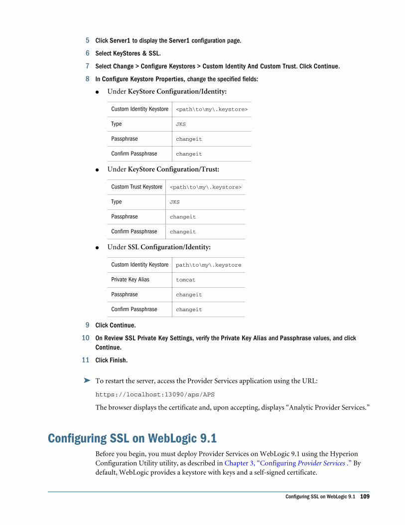
5 Click Server1 to display the Server1 configuration page.
6 Select KeyStores & SSL.
7 Select Change > Configure Keystores > Custom Identity And Custom Trust. Click Continue.
8 In Configure Keystore Properties, change the specified fields:
● Under KeyStore Configuration/Identity:
Custom Identity Keystore <path\to\my\.keystore>
Type JKS
Passphrase changeit
Confirm Passphrase changeit
● Under KeyStore Configuration/Trust:
Custom Trust Keystore <path\to\my\.keystore>
Type JKS
Passphrase changeit
Confirm Passphrase changeit
● Under SSL Configuration/Identity:
Custom Identity Keystore path\to\my\.keystore
Private Key Alias tomcat
Passphrase changeit
Confirm Passphrase changeit
9 Click Continue.
10 On Review SSL Private Key Settings, verify the Private Key Alias and Passphrase values, and clickContinue.
11 Click Finish.
➤ To restart the server, access the Provider Services application using the URL:
https://localhost:13090/aps/APS
The browser displays the certificate and, upon accepting, displays “Analytic Provider Services.”
Configuring SSL on WebLogic 9.1Before you begin, you must deploy Provider Services on WebLogic 9.1 using the HyperionConfiguration Utility utility, as described in Chapter 3, “Configuring Provider Services .” Bydefault, WebLogic provides a keystore with keys and a self-signed certificate.
Configuring SSL on WebLogic 9.1 109

Choose either a simple or a custom SSL setup as described in the following two sections.
Configuring a Simple SSL Setup on WebLogic
➤ To configure a simple SSL setup on WebLogic:
1 Start the WebLogic server in the following location:
Windows: <HYPERION_HOME>/deployments/WebLogic9/bin/StartWebLogic.cmd
Unix: <HYPERION_HOME>/deployments/WebLogic9/bin/StartWebLogic.sh
2 Open the WebLogic Admin console application, using the URL:
http://localhost:7001/console
3 Log in using the administrative user name and password. The default user name and password are bothhyperion.
4 In the left navigation pane, select Environment > Servers >aps.
5 Clicking aps to display the configuration page for aps.
6 In Change Center, click Lock & Edit .
7 Select General > SSL Listen Port Enabled > SSL Listen Port. Type 13090 (the port on which the serverlistens for HTTPS requests).
8 Click Save.
9 In Change Center, click Activate Changes.
10 Stop and restart the server.
11 Access Provider Services at :
https://localhost:13090/aps/APS
The browser presents you the certificate and, upon accepting, you will get the details with theProvider Services version and startup properties page.
Configuring a Custom SSL Setup on WebLogicYou may want to manage keys and certificates in a custom keystore. Before starting, you mustcomplete step 1 in “Configuring SSL on Tomcat” on page 105.
Note:
To configure the keystore for a WebLogic server, use the same key alias tomcat that was createdin step 1.
➤ To configure a custom SSL setup on WebLogic:
1 Start the WebLogic server.
110 Configuring Provider Services in SSL Mode

2 Open the Admin console application, using http://localhost:7001/console.
3 Log in as Admin.The default user name and password are both hyperion.
4 In the navigation pane, select Environment > Servers > aps.
5 To change the keystore configuration, select KeyStores > Change Center > Lock & Edit.
6 On the Configure Keystores page, select Custom Identity And Custom Trust. Click Continue.
7 On Configure Keystore Properties, change the specified fields:
● Under KeyStore Configuration/Identity:
Custom Identity Keystore <path\to\my\.keystore>
Type JKS
Passphrase changeit
Confirm Passphrase changeit
● Under KeyStore Configuration/Trust:
Custom Trust Keystore <path\to\my\.keystore>
Note: For this example, the keys and certificates are in the same keystore; however,they can be in different files.
Type JKS
Passphrase changeit
Confirm Passphrase changeit
8 Click Save.
9 Select SSL > Identity. Change the specified fields.
Private Key Alias tomcat
Passphrase changeit
Confirm Passphrase changeit
10 Click Save.
11 On the Review SSL Private Key Settings page, verify Private Key Alias and Passphrase values, and clickContinue.
12 Click Finish on the next page and restart the server.
13 Access Provider Services at:
https://localhost:13090/aps/APS
The browser presents the certificate, where you can verify the information that you specifiedabove. Upon accepting the certificate, you will get the details with the Provider Services versionand startup properties page.
Configuring SSL on WebLogic 9.1 111

Configuring SSL on WebSphere 6.0.2.11 and 6.1.0.5
Using the Default SSL ConfigurationAutodeploying Provider Services on WebSphere 6.0.2.11 using the Hyperion ConfigurationUtility does the following:
● Creates a new server profile with the name of the server you specified in HyperionConfiguration Utility; for example, APSServer.
● By default, this new profile has an SSL-enabled port assigned to this server; for example, ifthe specified port is 13080, then the SSL port of this server is assigned HTTPPort+2 =13082.
● Hyperion Configuration Utility then handles the autodeployment of Provider Services ontothis server. By default, Provider Services is hosted on the Default Port as well as DefaultSecurePort.
For example, running the Start APS Server script makes Provider Services available onSSL URL:
https: https://localhost:13082/aps/APS
Note:
In this scenario, WebSphere provides a keystore with keys and a self-signed certificate by default.
Using a Custom SSL ConfigurationTo use a custom SSL setting and configure Provider Services on WebSphere 6.0.2.11, follow theinstructions below.
Before you begin, ensure that the following prerequisites have been met:
● Install Provider Services and WebSphere 6.0.2.11
● Use the Hyperion Configuration Utility to autodeploy Provider Services on WebSphere6.0.2.11.
These instructions assume that you specified APSServer as the Server Name and 13080 asthe Port. Post-deployment, Provider Services is available on the default HTTP port 13080and HTTPS port 13082.
● For managed keys and certificates in a custom keystore only: You have a generated or alreadyhave a keystore (see step 1 of “Configuring SSL on Tomcat” on page 105 for keystorecreation).
For these instructions, assume you have created a keystore file, my.keystore in “c:\” withthe password changeit.
For example:
keytool -genkey -alias APS_WAS6 -keyalg RSA
112 Configuring Provider Services in SSL Mode

➤ To configure SSL on WebSphere 6.0.2.11:
1 Start Provider Services deployed on WebSphere.
For example, start it by running the script:
%APS_HOME%\bin\startAPSWebSphere60APSServer.bat
2 Launch WebSphere Admin Console in a browser.
The WebSphere Admin port for Provider Services is the Default Application Server Port plus 1.
For example, if you specified 13080 as the Provider Services port in the Hyperion ConfigurationUtility during autodeployment, then the WebSphere Admin Server port runs on 13081 and theWebSphere Admin Console URL would be:
http://localhost:13081/ibm/console
3 Log in to the WebSphere Admin console (typical login ID is admin).
4 Create a custom SSL profile for Provider Services:
To use a custom keystore, you must create an SSL Setting in WebSphere to use with the ProviderServices SSL-enabled Server.
a. Select Security > SSL.
b. Select New JSSE Repertoire > New SSL Configuration Repertoire. Complete the followingfields for the new SSL configuration for Provider Services:
Alias An identifier for your Provider Services SSL Setting; for example,APS_SSL_Settings
Key File Name The complete file path of your keystore file; for example, c:\my.keystore
Key File Password The password of your keystore; for example, changeit
Key File Format The key file format; for example, if your keystore is generated using the JDK Keytool utility,the format is JKS
Trust File Name The complete file path of your trust file; for example, often it is the same as Key FileName; therefore, c:\my.keystore
Trust File Password The password of your trust file; for example, changeit
Trust File Format The trust file format; for example, JKS
All other fields Retain the default values
c. Click Apply, then save your configuration.
5 Create a new HTTPS port to host Provider Services:
a. Select Servers > Application Servers > <Your APS Server instance> > Web ContainerSettings > Web container transport chains.
b. Click WCInboundDefaultSecure > SSL Inbound Channel (SSL_2). Modify the SSLrepertoire value by selecting your custom created SSL profile.
For example, select APSServer/APS_SSL_Settings.
Configuring SSL on WebSphere 6.0.2.11 and 6.1.0.5 113

c. Click Apply. Click OK, and save your configuration.
d. To change this SSL port, perform the following actions:
i. Select Servers > Application Servers > <Your APS Server instance > > Web ContainerSettings > Web container transport chains.
ii. Navigate to WCInboundDefaultSecure > TCP Inbound Channel (TCP_4) > Ports> WC_defaulthost_secure and specify the port of your choice, ensuring that the newport is not used already in your machine.
iii. Add this new HTTPS port to your to Provider Services Virtual Host:
● Select Environment > Virtual Hosts and select default_host.
● On the default Analytic Services Provider Virtual Host page, click HostAliases and add or modify the HTTPS port you added in the previous step.
For Host Name value, use an asterisk, *.
Modify port 13082 to 13090 or add another port 13090.
iv. Click Apply, and save this configuration.
6 Restart the Provider Services server.
7 Verify that you have successfully set up the Provider Services application on SSL by entering the SSL-enabledURL of Provider Services into a browser.
The URL syntax is:
https://<HOSTNAME>:HTTPS_PORT/aps/APS
HOSTNAME and HTTPS_PORT are the host name and HTTPS Port where Provider Services ishosted.
For example, if mymachine is the host name and 13090 is the HTTPS port on which the HTTPServer for Provider Services listens, enter the following URL into your browser:
https://mymachine:13090/aps/APS
Configuring SSL When WebSphere is Manually DeployedThe procedure for configuring SSL when WebSphere is manually deployed is similar to thatdescribed in “Using the Default SSL Configuration” on page 112.
The instructions for using a Custom Key Store are same as those described in “Using a CustomSSL Configuration” on page 112.
Complete manual deployment instructions WebSphere 6.0.2.11 are in “Deploying on IBMWebSphere Application Server 6.0.2 and 6.1.0.5” on page 176.
Keep in mind the following when you manually deploy:
● You have deployed aps.war on the application server server1 of WebSphere ApplicationServer.
server1 is the default after installing WebSphere, listening on HTTP port 9080. By default,server1 has an additional SSL-enabled port listening on 9443.
114 Configuring Provider Services in SSL Mode

● In the WebSphere Admin Console, note that default_host is the virtual host mapped toserver1.
Also, note that the SSL-enabled port 9443 of server1 is already part of thedefault_host Virtual Host; that is, there is no need to add the SSL-enabled port)
Configuring SSL on Oracle 10gBefore you begin, you should have already installed and manually deployed Oracle 10gapplication server as described in “Deploying on Oracle 10g – 10.1.2.0.2 or 10.1.3.1.0” on page178.
➤ To configure SSL on Oracle 10G:
1 Start Oracle Application Server 10G.
2 Execute $OAS_HOME/bin/SSLConfigTool.bat, accepting all defaults.
The script will give you the SSL port number.
3 Import the certificates.
The default wallet that is automatically installed with Oracle HTTP Server is for testing purposesonly. You must create a wallet for your production server. The default wallet is in:
ORACLE_HOME/Apache/Apache/conf/ssl.wlt/default
You can either place the new wallet in that location, or change the SSLWallet directive inORACLE_HOME/Apache/Apache/conf/ssl.conf to point to the location of your new wallet.
Configuring SSL on Oracle 10g 115

116 Configuring Provider Services in SSL Mode

11Working with XMLA
In This Chapter
Key Features... . . . . . . . . . . . . . . . . . . . . . . . . . . . . . . . . . . . . . . . . . . . . . . . . . . . . . . . . . . . . . . . . . . . . . . . . . . . . . . . . . . . . . . . . . . . . . . . . . . . . . . . . . . . . . . . . . . . 117
Methods ... . . . . . . . . . . . . . . . . . . . . . . . . . . . . . . . . . . . . . . . . . . . . . . . . . . . . . . . . . . . . . . . . . . . . . . . . . . . . . . . . . . . . . . . . . . . . . . . . . . . . . . . . . . . . . . . . . . . . . . . 117
XMLA Rowsets .. . . . . . . . . . . . . . . . . . . . . . . . . . . . . . . . . . . . . . . . . . . . . . . . . . . . . . . . . . . . . . . . . . . . . . . . . . . . . . . . . . . . . . . . . . . . . . . . . . . . . . . . . . . . . . . . . . . 123
Flattened Rowset Examples ... . . . . . . . . . . . . . . . . . . . . . . . . . . . . . . . . . . . . . . . . . . . . . . . . . . . . . . . . . . . . . . . . . . . . . . . . . . . . . . . . . . . . . . . . . . . . . . . . . . 152
Key FeaturesXML for Analysis (XMLA) is an open industry-standard Web service interface designed foronline analytical processing. XMLA is a set of XML Message Interfaces built on the openstandards of HTTP, XML, and Simple Object Access Protocol (SOAP). XMLA, which is notbound to any language, platform, or operating system, provides standardized data accessbetween client applications and any multidimensional data source on the Web.
For more information on XMLA, visit www.xmla.org.
Key XMLA features:
● Support for flattened rowsets
● Support for stateful sessions
● Backward XMLA level representation (level 1 is the top level)
● User authentication through basic HTTP authentication
● XMLA High-Availability functionality through Provider Services
● XMLA administration and monitoring through Oracle's Essbase® Administration Services
MethodsThe following methods provide a standard way for XML applications to access basic informationfrom the server. Because these methods are invoked using SOAP, they accept input and deliveroutput in XML. By default, these methods are stateless, so the server context ends at thecompletion of any command.
The simplified interface model has two methods.
● Discover
● Execute
Key Features 117

Discover obtains information and metadata from a Web Service. This information can includea list of available data sources and data about a data source provider. Properties define and shapethe data obtained. Discover allows you to specify the types of information that the clientapplication needs. The use of generic interface and properties enables extensibility withoutnecessitating rewriting existing functions.
Execute executes Multidimensional Expressions (MDX) or other provider-specific commandsagainst an XMLA data source. The following diagram illustrates a possible implementation ofan n-tiered application.
Provided with the URL for a server hosting a Web Service, the client uses SOAP and HTTPprotocols to send Discover and Execute calls to the server. The server instantiates the XMLAprovider, which handles the calls. The XMLA provider fetches the data, packages it into XML,and sends the data to the client.
The Discover and Execute methods enable users to determine what can be queried on a serverand, based on this, submit commands to be executed.
The XML namespace for these methods is “urn:schemas-microsoft-com:xml-analysis”.Connection information is supplied in each method call with the connection properties.
DiscoverThe Discover method retrieves information, such as the list of data sources on a server or detailsabout a data source. The data retrieved with the Discover method depends on the values of theparameters passed to it.
Namespace
urn:schemas-microsoft-com:xml-analysis
SOAP Action
"urn:schemas-microsoft-com:xml-analysis:Discover"
Syntax
118 Working with XMLA

Discover ( [in] RequestType As EnumString, [in] Restrictions As Restrictions, [in] Properties As Properties, [out] Result As Rowset)
Parameters
RequestType [in]
This required parameter comprises a RequestType enumeration value, which determines thetype of information to be returned. The RequestType enumeration is used by the Discovermethod to determine the structure and content of the rowset returned in the Result parameter.The Restrictions parameter format and XML result set are also dependent on the value specifiedin this parameter. This enumeration can be extended to support provider-specific enumerationstrings.
Each RequestType enumeration value corresponds to a return rowset. For rowset definitions,see “XMLA Rowsets” on page 123. Support is required for the following explicitly namedRequestType enumeration values.
Enumeration value Description
DISCOVER_DATASOURCES Returns a list of XMLA data sources available on the server or Web Service. (Foran example of how these may be published, see "XMLA ImplementationWalkthrough" in the XML for Analysis Specification, available on the HyperionDeveloper Network.)
DISCOVER_PROPERTIES Returns a list of information and values about the requested properties that aresupported by the specified data source (provider).
DISCOVER_SCHEMA_ROWSETS Returns the names, values, and other information of all supported RequestTypeenumeration values (including those listed here), and any additional provider-specific enumeration values.
DISCOVER_ENUMERATORS Returns a list of names, data types, and enumeration values of enumeratorssupported by the provider of a specific data source.
DISCOVER_KEYWORDS Returns a rowset containing a list of keywords reserved by the provider.
DISCOVER_LITERALS Returns information about literals supported by the data source provider. SchemaRowset Constant Given, a constant that corresponds to one of the schema rowsetnames defined by OLE DB, such as MDSCHEMA_CUBES, returns the OLE DBschema rowset in XML format. Note that providers also may extend OLEDB byproviding additional provider-specific schema rowsets. The schema rowsets thattabular data providers (TDP) and multidimensional data providers (MDP) arerequired to support are listed in the section "DISCOVER_SCHEMA_ROWSETSRowset."
Restrictions [in]
This parameter, of the Restrictions data type, enables the user to restrict the data returned inResult. Result columns are defined by the rowset specified in the RequestType parameter. Somecolumns of Result can filter the rows returned. For these columns and those that can be restricted,see the rowset tables in “XMLA Rowsets” on page 123. To obtain the restriction informationfor provider-specific schema rowsets, use the DISCOVER_SCHEMA_ROWSETS request type.This parameter can be empty, but it must be included.
Methods 119

Properties [in]
This parameter, of the Properties data type, comprises a collection of XMLA properties. Eachproperty enables users to control some aspect of the Discover method, such as specifying thereturn format of the result set, the timeout, or the locale in which the data should be formatted.
You can obtain the available properties by using the DISCOVER_PROPERTIES request typewith the Discover method.
The properties in the Properties parameter have no required order. This parameter can be empty,but it must be included.
Result [out]
This required parameter contains the result set returned by the provider as a Rowset object. Thecolumns and content of the result set are specified by the values in the RequestType andRestrictions parameters. The column layout of the returned result set also is determined by thevalue specified in RequestType. For information about the rowset layouts that correspond tofor each RequestType value, see “XMLA Rowsets” on page 123.
Example
In the following sample, the client sends the XML Discover call to request a list of cubes fromthe Demo catalog:
<SOAP-ENV:Envelope xmlns:SOAP-ENV="http://schemas.xmlsoap.org/soap/envelope/" xmlns:xsi = "http://www.w3.org/2001/XMLSchema-instance" xmlns:xsd="http://www.w3.org/2001/XMLSchema"> <SOAP-ENV:Body> <Discover xmlns="urn:schemas-microsoft-com:xml-analysis" SOAP-ENV:encodingStyle="http://schemas.xmlsoap.org/soap/encoding/"> <RequestType>MDSCHEMA_CUBES</RequestType> <Restrictions> <RestrictionList> <CATALOG_NAME>Demo</CATALOG_NAME> </RestrictionList> </Restrictions> <Properties> <PropertyList> <DataSourceInfo> Provider=Essbase;Data Source=localhost </DataSourceInfo> <Format>Tabular</Format> </PropertyList> </Properties> </Discover> </SOAP-ENV:Body></SOAP-ENV:Envelope>
The provider returns the following result to the client:
<?xml version="1.0"?><SOAP-ENV:Envelope xmlns:SOAP-ENV="http://schemas.xmlsoap.org/soap/envelope/" SOAP-ENV:encodingStyle="http://schemas.xmlsoap.org/soap/encoding/"> <SOAP-ENV:Body> <m:DiscoverResponse xmlns:m="urn:schemas-microsoft-com:xml-analysis">
120 Working with XMLA
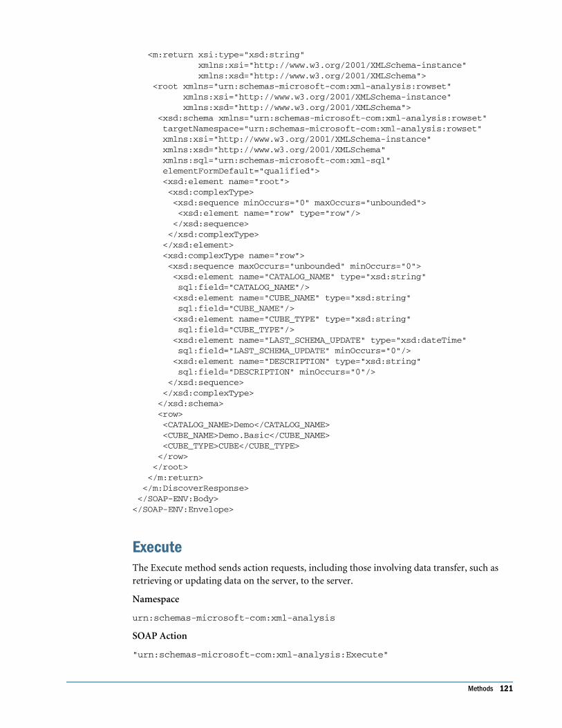
<m:return xsi:type="xsd:string" xmlns:xsi="http://www.w3.org/2001/XMLSchema-instance" xmlns:xsd="http://www.w3.org/2001/XMLSchema"> <root xmlns="urn:schemas-microsoft-com:xml-analysis:rowset" xmlns:xsi="http://www.w3.org/2001/XMLSchema-instance" xmlns:xsd="http://www.w3.org/2001/XMLSchema"> <xsd:schema xmlns="urn:schemas-microsoft-com:xml-analysis:rowset" targetNamespace="urn:schemas-microsoft-com:xml-analysis:rowset" xmlns:xsi="http://www.w3.org/2001/XMLSchema-instance" xmlns:xsd="http://www.w3.org/2001/XMLSchema" xmlns:sql="urn:schemas-microsoft-com:xml-sql" elementFormDefault="qualified"> <xsd:element name="root"> <xsd:complexType> <xsd:sequence minOccurs="0" maxOccurs="unbounded"> <xsd:element name="row" type="row"/> </xsd:sequence> </xsd:complexType> </xsd:element> <xsd:complexType name="row"> <xsd:sequence maxOccurs="unbounded" minOccurs="0"> <xsd:element name="CATALOG_NAME" type="xsd:string" sql:field="CATALOG_NAME"/> <xsd:element name="CUBE_NAME" type="xsd:string" sql:field="CUBE_NAME"/> <xsd:element name="CUBE_TYPE" type="xsd:string" sql:field="CUBE_TYPE"/> <xsd:element name="LAST_SCHEMA_UPDATE" type="xsd:dateTime" sql:field="LAST_SCHEMA_UPDATE" minOccurs="0"/> <xsd:element name="DESCRIPTION" type="xsd:string" sql:field="DESCRIPTION" minOccurs="0"/> </xsd:sequence> </xsd:complexType> </xsd:schema> <row> <CATALOG_NAME>Demo</CATALOG_NAME> <CUBE_NAME>Demo.Basic</CUBE_NAME> <CUBE_TYPE>CUBE</CUBE_TYPE> </row> </root> </m:return> </m:DiscoverResponse> </SOAP-ENV:Body></SOAP-ENV:Envelope>
ExecuteThe Execute method sends action requests, including those involving data transfer, such asretrieving or updating data on the server, to the server.
Namespace
urn:schemas-microsoft-com:xml-analysis
SOAP Action
"urn:schemas-microsoft-com:xml-analysis:Execute"
Methods 121

Syntax
Execute ( [in] Command As Command, [in] Properties As Properties, [out] Result As Resultset)
Parameters
Command [in]
This required parameter is of Command data type and consists of an MDX statement to beexecuted.
Properties [in]
This parameter is of the Properties data type and consists of a collection of XMLA properties.Each property allows the user to control some aspect of the Execute method, such as definingthe information required for the connection, specifying the return format of the result set, orspecifying the locale in which the data should be formatted.
The available properties and their values can be obtained by using theDISCOVER_PROPERTIES request type with the Discover method. Standard XMLA propertiesare detailed in “XML for Analysis Properties.”
The properties in the Properties parameter have no required order. This parameter can be empty,but it must be included.
Result [out]
This parameter contains the Resultset result returned by the provider. The Command parameterand values in the Properties parameter define the shape of the result set. If no shape-definingproperties are passed, the XMLA provider may use a default shape. The two result set formatsdefined by this specification are Tabular and Multidimensional, as specified by the client throughthe Format property. OLAP data lends itself to the Multidimensional format (although theTabular format also can be used). A provider may support additional rowset types, and clientsaware of the specialized types can request them.
Example
The following is an example of an Execute method call with <Statement> set to an MDX SELECTstatement:
<SOAP-ENV:Envelope xmlns:SOAP-ENV="http://schemas.xmlsoap.org/soap/envelope/" xmlns:xsi = "http://www.w3.org/2001/XMLSchema-instance" xmlns:xsd="http://www.w3.org/2001/XMLSchema">
<SOAP-ENV:Body> <Execute xmlns="urn:schemas-microsoft-com:xml-analysis" SOAP-ENV:encodingStyle="http://schemas.xmlsoap.org/soap/encoding/"> <Command> <Statement> SELECT CrossJoin([Measures].CHILDREN , [Market].CHILDREN) on columns, [Product].Members on rows from Sample.Basic </Statement> </Command>
122 Working with XMLA

<Properties> <PropertyList> <DataSourceInfo> Provider=Essbase;Data Source=localhost </DataSourceInfo> <Catalog>Sample</Catalog> <Format>Multidimensional</Format> <AxisFormat>TupleFormat</AxisFormat> <Content>SchemaData</Content> </PropertyList></Properties> </Execute> </SOAP-ENV:Body></SOAP-ENV:Envelope>
The abbreviated response for the preceding method call:
<?xml version="1.0"?><SOAP-ENV:Envelope xmlns:SOAP-ENV="http://schemas.xmlsoap.org/soap/envelope/" SOAP-ENV:encodingStyle="http://schemas.xmlsoap.org/soap/encoding/"> <SOAP-ENV:Body> <m:ExecuteResponse xmlns:m="urn:schemas-microsoft-com:xml-analysis"> <m:return SOAP-ENV:encodingStyle="http://schemas.xmlsoap.org/soap/encoding/"> <root xmlns="urn:schemas-microsoft-com:xml-analysis:mddataset"> <xsd:schema xmlns:xsd="http://www.w3.org/2001/XMLSchema" xmlns:xars="urn:schemas-microsoft-com:xars"> ...<!-The schema for the data goes here. -- > </xsd:schema> ... <!-The data in MDDataSet format goes here. -- > </root> </m:return> </m:ExecuteResponse> </SOAP-ENV:Body></SOAP-ENV:Envelope>
XMLA RowsetsInformation returned in the Result parameter of the Discover method is structured accordingto the rowset column layouts detailed in this section.
CATALOGS RowsetThe CATALOGS rowset identifies the physical attributes associated with catalogs accessible fromAnalytic Services.
GUID: DBSCHEMA_CATALOGS
The following table describes the rowset structure.
Column name Essbase Mapping
XMLA Rowsets 123

CATALOG_NAME Application name
DESCRIPTION Always null
Request Example
<SOAP-ENV:Envelope xmlns:SOAP-ENV="http://schemas.xmlsoap.org/soap/envelope/" xmlns:xsi = "http://www.w3.org/2001/XMLSchema-instance" xmlns:xsd="http://www.w3.org/2001/XMLSchema"> <SOAP-ENV:Body> <Discover xmlns="urn:schemas-microsoft-com:xml-analysis" SOAP-ENV:encodingStyle="http://schemas.xmlsoap.org/soap/encoding/"> <RequestType>DBSCHEMA_CATALOGS</RequestType> <Restrictions> <RestrictionList></RestrictionList> </Restrictions> <Properties> <PropertyList> <DataSourceInfo>Provider=Essbase;Data Source=localhost </DataSourceInfo> <Format>Tabular</Format> </PropertyList> </Properties> </Discover> </SOAP-ENV:Body></SOAP-ENV:Envelope>
Response Example (truncated)
<?xml version="1.0"?><SOAP-ENV:Envelope xmlns:SOAP-ENV="http://schemas.xmlsoap.org/soap/envelope/" SOAP-ENV:encodingStyle="http://schemas.xmlsoap.org/soap/encoding/"> <SOAP-ENV:Body> <m:DiscoverResponse xmlns:m="urn:schemas-microsoft-com:xml-analysis"> <m:return xsi:type="xsd:string" xmlns:xsi="http://www.w3.org/2001/XMLSchema-instance" xmlns:xsd="http://www.w3.org/2001/XMLSchema"> <root xmlns="urn:schemas-microsoft-com:xml-analysis:rowset" xmlns:xsi="http://www.w3.org/2001/XMLSchema-instance" xmlns:xsd="http://www.w3.org/2001/XMLSchema"> <xsd:schema xmlns="urn:schemas-microsoft-com:xml-analysis:rowset" targetNamespace="urn:schemas-microsoft-com:xml-analysis:rowset" xmlns:xsi="http://www.w3.org/2001/XMLSchema-instance" xmlns:xsd="http://www.w3.org/2001/XMLSchema" xmlns:sql="urn:schemas-microsoft-com:xml-sql" elementFormDefault="qualified"> <xsd:element name="root"> <xsd:complexType> <xsd:sequence minOccurs="0" maxOccurs="unbounded"> <xsd:element name="row" type="row"/> </xsd:sequence> </xsd:complexType> </xsd:element> <xsd:complexType name="row"> <xsd:sequence maxOccurs="unbounded" minOccurs="0"> <xsd:element name="CATALOG_NAME" type="xsd:string"
124 Working with XMLA

sql:field="CATALOG_NAME"/> <xsd:element name="DESCRIPTION" type="xsd:string" sql:field="DESCRIPTION" minOccurs="0"/> </xsd:sequence> </xsd:complexType> </xsd:schema> <row> <CATALOG_NAME>Demo</CATALOG_NAME> </row> < ................More Rows............. > </root> </m:return> </m:DiscoverResponse> </SOAP-ENV:Body></SOAP-ENV:Envelope>
MDSCHEMA_CUBES RowsetThe CUBES rowset contains information about the available cubes in a schema (or the catalog,if the provider does not support schemas).
GUID: MDSCHEMA_CUBES
The rowset has the structure described in the following table.
Column name Essbase Mapping
CATALOG_NAME Application name
CUBE_NAME Database name
CUBE_TYPE “CUBE”
LAST_SCHEMA_UPDATE Time stamp of last outline update
DESCRIPTION Database description
Request Example
<SOAP-ENV:Envelope xmlns:SOAP-ENV="http://schemas.xmlsoap.org/soap/envelope/" xmlns:xsi = "http://www.w3.org/2001/XMLSchema-instance" xmlns:xsd="http://www.w3.org/2001/XMLSchema"> <SOAP-ENV:Body> <Discover xmlns="urn:schemas-microsoft-com:xml-analysis" SOAP-ENV:encodingStyle="http://schemas.xmlsoap.org/soap/encoding/"> <RequestType>MDSCHEMA_CUBES</RequestType> <Restrictions> <RestrictionList> <CATALOG_NAME>Demo</CATALOG_NAME> </RestrictionList> </Restrictions> <Properties> <PropertyList> <DataSourceInfo> Provider=Essbase;Data Source=localhost
XMLA Rowsets 125

</DataSourceInfo> <Format>Tabular</Format> </PropertyList> </Properties> </Discover> </SOAP-ENV:Body></SOAP-ENV:Envelope>
Response Example
<?xml version="1.0"?><SOAP-ENV:Envelope xmlns:SOAP-ENV="http://schemas.xmlsoap.org/soap/envelope/" SOAP-ENV:encodingStyle="http://schemas.xmlsoap.org/soap/encoding/"> <SOAP-ENV:Body> <m:DiscoverResponse xmlns:m="urn:schemas-microsoft-com:xml-analysis"> <m:return xsi:type="xsd:string" xmlns:xsi="http://www.w3.org/2001/XMLSchema-instance" xmlns:xsd="http://www.w3.org/2001/XMLSchema"> <root xmlns="urn:schemas-microsoft-com:xml-analysis:rowset" xmlns:xsi="http://www.w3.org/2001/XMLSchema-instance" xmlns:xsd="http://www.w3.org/2001/XMLSchema"> <xsd:schema xmlns="urn:schemas-microsoft-com:xml-analysis:rowset" targetNamespace="urn:schemas-microsoft-com:xml-analysis:rowset" xmlns:xsi="http://www.w3.org/2001/XMLSchema-instance" xmlns:xsd="http://www.w3.org/2001/XMLSchema" xmlns:sql="urn:schemas-microsoft-com:xml-sql" elementFormDefault="qualified"> <xsd:element name="root"> <xsd:complexType> <xsd:sequence minOccurs="0" maxOccurs="unbounded"> <xsd:element name="row" type="row"/> </xsd:sequence> </xsd:complexType> </xsd:element> <xsd:complexType name="row"> <xsd:sequence maxOccurs="unbounded" minOccurs="0"> <xsd:element name="CATALOG_NAME" type="xsd:string" sql:field="CATALOG_NAME"/> <xsd:element name="CUBE_NAME" type="xsd:string" sql:field="CUBE_NAME"/> <xsd:element name="CUBE_TYPE" type="xsd:string" sql:field="CUBE_TYPE"/> <xsd:element name="LAST_SCHEMA_UPDATE" type="xsd:dateTime" sql:field="LAST_SCHEMA_UPDATE" minOccurs="0"/> <xsd:element name="DESCRIPTION" type="xsd:string" sql:field="DESCRIPTION" minOccurs="0"/> </xsd:sequence> </xsd:complexType> </xsd:schema> <row> <CATALOG_NAME>Demo</CATALOG_NAME> <CUBE_NAME>Demo.Basic</CUBE_NAME> <CUBE_TYPE>CUBE</CUBE_TYPE> </row> </root> </m:return> </m:DiscoverResponse>
126 Working with XMLA

</SOAP-ENV:Body></SOAP-ENV:Envelope>
MDSCHEMA_DIMENSIONS RowsetThe DIMENSIONS rowset contains information about the dimensions in a given cube. Eachdimension has one row.
GUID: MDSCHEMA_DIMENSIONS
The rowset has the structure described in the following table.
Column name Essbase Mapping
CATALOG_NAME Application name
CUBE_NAME Database name
DIMENSION_NAME Dimension name
DIMENSION_UNIQUE_NAME Dimension name
DIMENSION_CAPTION Dimension name
DIMENSION_ORDINAL Dimension number. First dimension is 1, second is 2, and so on
DIMENSION_TYPE If Essbase dimension type is:
● TIME: MD_DIMTYPE_TIME
● ACCOUNTS: MD_DIMTYPE_MEASURE
● ALL OTHER: MD_DIMTYPE_OTHER
DIMENSION_CARDINALITY Number of members in the dimension
DEFAULT_HIERARCHY Dimension name
DESCRIPTION Comment added for the dimension
DIMENSION_UNIQUE_SETTINGS 2
DIMENSION_IS_VISIBLE True always
Request Example
<SOAP-ENV:Envelope xmlns:SOAP-ENV="http://schemas.xmlsoap.org/soap/envelope/" xmlns:xsi = "http://www.w3.org/2001/XMLSchema-instance" xmlns:xsd="http://www.w3.org/2001/XMLSchema"> <SOAP-ENV:Body> <Discover xmlns="urn:schemas-microsoft-com:xml-analysis" SOAP-ENV:encodingStyle="http://schemas.xmlsoap.org/soap/encoding/"> <RequestType>MDSCHEMA_DIMENSIONS</RequestType> <Restrictions> <RestrictionList> <CATALOG_NAME>Sample</CATALOG_NAME> <CUBE_NAME>Basic</CUBE_NAME>
XMLA Rowsets 127

</RestrictionList> </Restrictions> <Properties> <PropertyList> <DataSourceInfo>Provider=Essbase;Data Source=localhost </DataSourceInfo> <Format>Tabular</Format> </PropertyList> </Properties> </Discover> </SOAP-ENV:Body></SOAP-ENV:Envelope>
Response Example(truncated)
<?xml version="1.0"?><SOAP-ENV:Envelope xmlns:SOAP-ENV="http://schemas.xmlsoap.org/soap/envelope/" SOAP-ENV:encodingStyle="http://schemas.xmlsoap.org/soap/encoding/"> <SOAP-ENV:Body> <m:DiscoverResponse xmlns:m="urn:schemas-microsoft-com:xml-analysis"> <m:return xsi:type="xsd:string" xmlns:xsi="http://www.w3.org/2001/XMLSchema-instance" xmlns:xsd="http://www.w3.org/2001/XMLSchema"> <root xmlns="urn:schemas-microsoft-com:xml-analysis:rowset" xmlns:xsi="http://www.w3.org/2001/XMLSchema-instance" xmlns:xsd="http://www.w3.org/2001/XMLSchema"> <xsd:schema xmlns="urn:schemas-microsoft-com:xml-analysis:rowset" targetNamespace="urn:schemas-microsoft-com:xml-analysis:rowset" xmlns:xsi="http://www.w3.org/2001/XMLSchema-instance" xmlns:xsd="http://www.w3.org/2001/XMLSchema" xmlns:sql="urn:schemas-microsoft-com:xml-sql" elementFormDefault="qualified"> <xsd:element name="root"> <xsd:complexType> <xsd:sequence minOccurs="0" maxOccurs="unbounded"> <xsd:element name="row" type="row"/> </xsd:sequence> </xsd:complexType> </xsd:element> <xsd:complexType name="row"> <xsd:sequence maxOccurs="unbounded" minOccurs="0"> <xsd:element name="CATALOG_NAME" type="xsd:string" sql:field="CATALOG_NAME"/> <xsd:element name="CUBE_NAME" type="xsd:string" sql:field="CUBE_NAME"/> <xsd:element name="DIMENSION_NAME" type="xsd:string" sql:field="DIMENSION_NAME"/> <xsd:element name="DIMENSION_UNIQUE_NAME" type="xsd:string" sql:field="DIMENSION_UNIQUE_NAME"/> <xsd:element name="DIMENSION_CAPTION" type="xsd:string" sql:field="DIMENSION_CAPTION"/> <xsd:element name="DIMENSION_ORDINAL" type="xsd:unsignedInt" sql:field="DIMENSION_ORDINAL"/> <xsd:element name="DIMENSION_TYPE" type="xsd:short" sql:field="DIMENSION_TYPE"/> <xsd:element name="DIMENSION_CARDINALITY" type="xsd:unsignedInt" sql:field="DIMENSION_CARDINALITY"/>
128 Working with XMLA

<xsd:element name="DEFAULT_HIERARCHY" type="xsd:string" sql:field="DEFAULT_HIERARCHY"/> <xsd:element name="DESCRIPTION" type="xsd:string" sql:field="DESCRIPTION" minOccurs="0"/> <xsd:element name="DIMENSION_UNIQUE_SETTINGS" type="xsd:int" sql:field="DIMENSION_UNIQUE_SETTINGS"/> <xsd:element name="DIMENSION_IS_VISIBLE" type="xsd:boolean" sql:field="DIMENSION_IS_VISIBLE"/> </xsd:sequence> </xsd:complexType> </xsd:schema> <row> <CATALOG_NAME>Sample</CATALOG_NAME> <CUBE_NAME>Sample.Basic</CUBE_NAME> <DIMENSION_NAME>Year</DIMENSION_NAME> <DIMENSION_UNIQUE_NAME>[Year]</DIMENSION_UNIQUE_NAME> <DIMENSION_CAPTION>Year</DIMENSION_CAPTION> <DIMENSION_ORDINAL>1</DIMENSION_ORDINAL> <DIMENSION_TYPE>1</DIMENSION_TYPE> <DIMENSION_CARDINALITY>19</DIMENSION_CARDINALITY> <DEFAULT_HIERARCHY>[Year]</DEFAULT_HIERARCHY> <DIMENSION_UNIQUE_SETTINGS>2</DIMENSION_UNIQUE_SETTINGS> <DIMENSION_IS_VISIBLE>true</DIMENSION_IS_VISIBLE> </row> < ................More Rows............. > </root> </m:return> </m:DiscoverResponse> </SOAP-ENV:Body></SOAP-ENV:Envelope>
MDSCHEMA_FUNCTIONS RowsetThe FUNCTIONS rowset exposes all functions supported by the MDP. Default sort order:ORIGIN, INTERFACE_NAME, and FUNCTION_NAME.
GUID: MDSCHEMA_FUNCTIONS
The following table describes the rowset structure.
Column name Essbase Mapping
FUNCTION_NAME Name of the function
DESCRIPTION Description of the function
PARAM_LIST A comma delimited list of parameters
RETURN_TYPE Always 12
ORIGIN 1 (always:MDX functions)
INTERFACE_NAME One of the following: Member, Set, Tuple, Numeric, Dimension, Level, Boolean
OBJECT One of the following values: Set, Member, Tuple, Level, Hierarchy, Dimension
XMLA Rowsets 129

HELP_CONTEXT Help context ID for the function
CAPTION Display caption of the function
Request Example
<SOAP-ENV:Envelope xmlns:SOAP-ENV="http://schemas.xmlsoap.org/soap/envelope/" xmlns:xsi = "http://www.w3.org/2001/XMLSchema-instance" xmlns:xsd="http://www.w3.org/2001/XMLSchema"> <SOAP-ENV:Body> <Discover xmlns="urn:schemas-microsoft-com:xml-analysis" SOAP-ENV:encodingStyle="http://schemas.xmlsoap.org/soap/encoding/"> <RequestType>MDSCHEMA_FUNCTIONS</RequestType> <Restrictions><RestrictionList></RestrictionList></Restrictions> <Properties> <PropertyList> <DataSourceInfo>Provider=Essbase;Data Source=localhost </DataSourceInfo> <Format>Tabular</Format> </PropertyList> </Properties> </Discover> </SOAP-ENV:Body></SOAP-ENV:Envelope>
Response Example (truncated)
<?xml version="1.0"?><SOAP-ENV:Envelope xmlns:SOAP-ENV="http://schemas.xmlsoap.org/soap/envelope/" SOAP-ENV:encodingStyle="http://schemas.xmlsoap.org/soap/encoding/"> <SOAP-ENV:Body> <m:DiscoverResponse xmlns:m="urn:schemas-microsoft-com:xml-analysis"> <m:return xsi:type="xsd:string" xmlns:xsi="http://www.w3.org/2001/XMLSchema-instance" xmlns:xsd="http://www.w3.org/2001/XMLSchema"> <root xmlns="urn:schemas-microsoft-com:xml-analysis:rowset" xmlns:xsi="http://www.w3.org/2001/XMLSchema-instance" xmlns:xsd="http://www.w3.org/2001/XMLSchema"> <xsd:schema xmlns="urn:schemas-microsoft-com:xml-analysis:rowset" targetNamespace="urn:schemas-microsoft-com:xml-analysis:rowset" xmlns:xsi="http://www.w3.org/2001/XMLSchema-instance" xmlns:xsd="http://www.w3.org/2001/XMLSchema" xmlns:sql="urn:schemas-microsoft-com:xml-sql" elementFormDefault="qualified"> <xsd:element name="root"> <xsd:complexType> <xsd:sequence minOccurs="0" maxOccurs="unbounded"> <xsd:element name="row" type="row"/> </xsd:sequence> </xsd:complexType> </xsd:element> <xsd:complexType name="row"> <xsd:sequence maxOccurs="unbounded" minOccurs="0"> <xsd:element name="FUNCTION_NAME" type="xsd:string" sql:field="FUNCTION_NAME"/> <xsd:element name="DESCRIPTION" type="xsd:string"
130 Working with XMLA
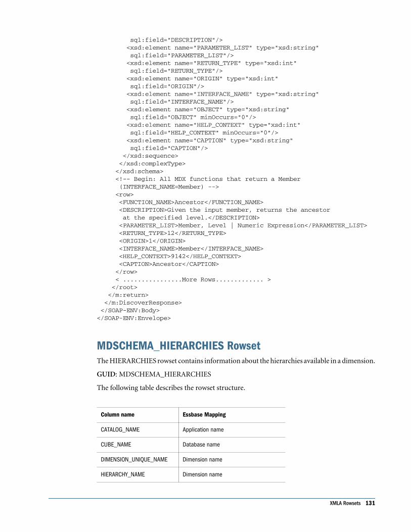
sql:field="DESCRIPTION"/> <xsd:element name="PARAMETER_LIST" type="xsd:string" sql:field="PARAMETER_LIST"/> <xsd:element name="RETURN_TYPE" type="xsd:int" sql:field="RETURN_TYPE"/> <xsd:element name="ORIGIN" type="xsd:int" sql:field="ORIGIN"/> <xsd:element name="INTERFACE_NAME" type="xsd:string" sql:field="INTERFACE_NAME"/> <xsd:element name="OBJECT" type="xsd:string" sql:field="OBJECT" minOccurs="0"/> <xsd:element name="HELP_CONTEXT" type="xsd:int" sql:field="HELP_CONTEXT" minOccurs="0"/> <xsd:element name="CAPTION" type="xsd:string" sql:field="CAPTION"/> </xsd:sequence> </xsd:complexType> </xsd:schema> <!-- Begin: All MDX functions that return a Member (INTERFACE_NAME=Member) --> <row> <FUNCTION_NAME>Ancestor</FUNCTION_NAME> <DESCRIPTION>Given the input member, returns the ancestor at the specified level.</DESCRIPTION> <PARAMETER_LIST>Member, Level | Numeric Expression</PARAMETER_LIST> <RETURN_TYPE>12</RETURN_TYPE> <ORIGIN>1</ORIGIN> <INTERFACE_NAME>Member</INTERFACE_NAME> <HELP_CONTEXT>9142</HELP_CONTEXT> <CAPTION>Ancestor</CAPTION> </row> < ................More Rows............. > </root> </m:return> </m:DiscoverResponse> </SOAP-ENV:Body></SOAP-ENV:Envelope>
MDSCHEMA_HIERARCHIES RowsetThe HIERARCHIES rowset contains information about the hierarchies available in a dimension.
GUID: MDSCHEMA_HIERARCHIES
The following table describes the rowset structure.
Column name Essbase Mapping
CATALOG_NAME Application name
CUBE_NAME Database name
DIMENSION_UNIQUE_NAME Dimension name
HIERARCHY_NAME Dimension name
XMLA Rowsets 131

HIERARCHY_UNIQUE_NAME Dimension name
HIERARCHY_CAPTION Dimension name
DIMENSION_TYPE If Essbase dimension type is:
● TIME: MD_DIMTYPE_TIME
● ACCOUNTS: MD_DIMTYPE_MEASSURE
● ALL OTHER: MD_DIMTYPE_OTHER
HIERARCHY_CARDINALITY Number of members in the dimension.
DEFAULT_MEMBER Dimension name
ALL_MEMBER Dimension name
DESCRIPTION Dimension comment
STRUCTURE MD_STRUCTURE_UNBALANCED(2)
HIERARCHY_UNIQUE_SETTINGS 2
HIERARCHY_IS_VISIBLE True
Request Example
<SOAP-ENV:Envelope xmlns:SOAP-ENV="http://schemas.xmlsoap.org/soap/envelope/" xmlns:xsi = "http://www.w3.org/2001/XMLSchema-instance" xmlns:xsd="http://www.w3.org/2001/XMLSchema"> <SOAP-ENV:Body> <Discover xmlns="urn:schemas-microsoft-com:xml-analysis" SOAP-ENV:encodingStyle="http://schemas.xmlsoap.org/soap/encoding/"> <RequestType>MDSCHEMA_HIERARCHIES</RequestType> <Restrictions> <RestrictionList> <CUBE_NAME>Sample.Basic</CUBE_NAME> <DIMENSION_UNIQUE_NAME>Year</DIMENSION_UNIQUE_NAME> </RestrictionList> </Restrictions> <Properties> <PropertyList> <DataSourceInfo>Provider=Essbase;Data Source=localhost </DataSourceInfo> <Format>Tabular</Format> </PropertyList> </Properties> </Discover> </SOAP-ENV:Body></SOAP-ENV:Envelope>
Response Example
<?xml version="1.0"?><SOAP-ENV:Envelope xmlns:SOAP-ENV="http://schemas.xmlsoap.org/soap/envelope/" SOAP-ENV:encodingStyle="http://schemas.xmlsoap.org/soap/encoding/"> <SOAP-ENV:Body>
132 Working with XMLA

<m:DiscoverResponse xmlns:m="urn:schemas-microsoft-com:xml-analysis"> <m:return xsi:type="xsd:string" xmlns:xsi="http://www.w3.org/2001/XMLSchema-instance" xmlns:xsd="http://www.w3.org/2001/XMLSchema"> <root xmlns="urn:schemas-microsoft-com:xml-analysis:rowset" xmlns:xsi="http://www.w3.org/2001/XMLSchema-instance" xmlns:xsd="http://www.w3.org/2001/XMLSchema"> <xsd:schema xmlns="urn:schemas-microsoft-com:xml-analysis:rowset" targetNamespace="urn:schemas-microsoft-com:xml-analysis:rowset" xmlns:xsi="http://www.w3.org/2001/XMLSchema-instance" xmlns:xsd="http://www.w3.org/2001/XMLSchema" xmlns:sql="urn:schemas-microsoft-com:xml-sql" elementFormDefault="qualified"> <xsd:element name="root"> <xsd:complexType> <xsd:sequence minOccurs="0" maxOccurs="unbounded"> <xsd:element name="row" type="row"/> </xsd:sequence> </xsd:complexType> </xsd:element> <xsd:complexType name="row"> <xsd:sequence maxOccurs="unbounded" minOccurs="0"> <xsd:element name="CATALOG_NAME" type="xsd:string" sql:field="CATALOG_NAME"/> <xsd:element name="CUBE_NAME" type="xsd:string" sql:field="CUBE_NAME"/> <xsd:element name="DIMENSION_UNIQUE_NAME" type="xsd:string" sql:field="DIMENSION_UNIQUE_NAME"/> <xsd:element name="HIERARCHY_NAME" type="xsd:string" sql:field="HIERARCHY_NAME"/> <xsd:element name="HIERARCHY_UNIQUE_NAME" type="xsd:string" sql:field="HIERARCHY_UNIQUE_NAME"/> <xsd:element name="HIERARCHY_CAPTION" type="xsd:string" sql:field="HIERARCHY_CAPTION"/> <xsd:element name="DIMENSION_TYPE" type="xsd:short" sql:field="DIMENSION_TYPE"/> <xsd:element name="HIERARCHY_CARDINALITY" type="xsd:unsignedInt" sql:field="HIERARCHY_CARDINALITY"/> <xsd:element name="DEFAULT_MEMBER" type="xsd:string" sql:field="DEFAULT_MEMBER"/> <xsd:element name="ALL_MEMBER" type="xsd:string" sql:field="ALL_MEMBER"/> <xsd:element name="DESCRIPTION" type="xsd:string" sql:field="DESCRIPTION" minOccurs="0"/> <xsd:element name="STRUCTURE" type="xsd:int" sql:field="STRUCTURE"/> <xsd:element name="HIERARCHY_UNIQUE_SETTINGS" type="xsd:int" sql:field="HIERARCHY_UNIQUE_SETTINGS"/> <xsd:element name="HIERARCHY_IS_VISIBLE" type="xsd:boolean" sql:field="HIERARCHY_IS_VISIBLE"/> </xsd:sequence> </xsd:complexType> </xsd:schema> <row> <CATALOG_NAME>Sample</CATALOG_NAME> <CUBE_NAME>Sample.Basic</CUBE_NAME> <DIMENSION_UNIQUE_NAME>[Year]</DIMENSION_UNIQUE_NAME>
XMLA Rowsets 133

<HIERARCHY_NAME>Year</HIERARCHY_NAME> <HIERARCHY_UNIQUE_NAME>[Year]</HIERARCHY_UNIQUE_NAME> <HIERARCHY_CAPTION>Year</HIERARCHY_CAPTION> <DIMENSION_TYPE>1</DIMENSION_TYPE> <HIERARCHY_CARDINALITY>19</HIERARCHY_CARDINALITY> <DEFAULT_MEMBER>[Year]</DEFAULT_MEMBER> <ALL_MEMBER>[Year]</ALL_MEMBER> <STRUCTURE>2</STRUCTURE> <HIERARCHY_UNIQUE_SETTINGS>2</HIERARCHY_UNIQUE_SETTINGS> <HIERARCHY_IS_VISIBLE>true</HIERARCHY_IS_VISIBLE> </row> </root> </m:return> </m:DiscoverResponse> </SOAP-ENV:Body></SOAP-ENV:Envelope>
MDSCHEMA_MEASURES RowsetThe MEASURES rowset contains information about the available measures.
GUID: MDSCHEMA_MEASURES
The following table describes the rowset structure.
Column name Essbase Mapping
CATALOG_NAME Application name
CUBE_NAME Database name
MEASURE_NAME Member names in the Accounts dimension
MEASURE_UNIQUE_NAME Above member name
MEASURE_CAPTION Above member name
MEASURE_AGGREGATOR Essbase ADDITION: 1
Essbase SUBSTRACTION: 17
Essbase MULTIPLICATION:18
Essbase DIVISION:19
Essbase PERCENT:20
Essbase NOOP: 21
DESCRIPTION Member comment
DATA_TYPE 5
EXPRESSION Member formula
MEASURE_IS_VISIBLE True
Request Example
134 Working with XMLA

<SOAP-ENV:Envelope xmlns:SOAP-ENV="http://schemas.xmlsoap.org/soap/envelope/" xmlns:xsi = "http://www.w3.org/2001/XMLSchema-instance" xmlns:xsd="http://www.w3.org/2001/XMLSchema"> <SOAP-ENV:Body> <Discover xmlns="urn:schemas-microsoft-com:xml-analysis" SOAP-ENV:encodingStyle="http://schemas.xmlsoap.org/soap/encoding/"> <RequestType>MDSCHEMA_MEASURES</RequestType> <Restrictions> <RestrictionList> <CATALOG_NAME>Sample</CATALOG_NAME> <CUBE_NAME>Basic</CUBE_NAME> </RestrictionList> </Restrictions> <Properties> <PropertyList> <DataSourceInfo>Provider=Essbase;Data Source=localhost </DataSourceInfo> <Format>Tabular</Format> </PropertyList> </Properties> </Discover> </SOAP-ENV:Body></SOAP-ENV:Envelope>
Response Example(truncated)
<?xml version="1.0"?><SOAP-ENV:Envelope xmlns:SOAP-ENV="http://schemas.xmlsoap.org/soap/envelope/" SOAP-ENV:encodingStyle="http://schemas.xmlsoap.org/soap/encoding/"> <SOAP-ENV:Body> <m:DiscoverResponse xmlns:m="urn:schemas-microsoft-com:xml-analysis"> <m:return xsi:type="xsd:string" xmlns:xsi="http://www.w3.org/2001/XMLSchema-instance" xmlns:xsd="http://www.w3.org/2001/XMLSchema"> <root xmlns="urn:schemas-microsoft-com:xml-analysis:rowset" xmlns:xsi="http://www.w3.org/2001/XMLSchema-instance" xmlns:xsd="http://www.w3.org/2001/XMLSchema"> <xsd:schema xmlns="urn:schemas-microsoft-com:xml-analysis:rowset" targetNamespace="urn:schemas-microsoft-com:xml-analysis:rowset" xmlns:xsi="http://www.w3.org/2001/XMLSchema-instance" xmlns:xsd="http://www.w3.org/2001/XMLSchema" xmlns:sql="urn:schemas-microsoft-com:xml-sql" elementFormDefault="qualified"> <xsd:element name="root"> <xsd:complexType> <xsd:sequence minOccurs="0" maxOccurs="unbounded"> <xsd:element name="row" type="row"/> </xsd:sequence> </xsd:complexType> </xsd:element> <xsd:complexType name="row"> <xsd:sequence maxOccurs="unbounded" minOccurs="0"> <xsd:element name="CATALOG_NAME" type="xsd:string" sql:field="CATALOG_NAME"/> <xsd:element name="CUBE_NAME" type="xsd:string" sql:field="CUBE_NAME"/>
XMLA Rowsets 135

<xsd:element name="MEASURE_NAME" type="xsd:string" sql:field="MEASURE_NAME"/> <xsd:element name="MEASURE_UNIQUE_NAME" type="xsd:string" sql:field="MEASURE_UNIQUE_NAME"/> <xsd:element name="MEASURE_CAPTION" type="xsd:string" sql:field="MEASURE_CAPTION"/> <xsd:element name="MEASURE_AGGREGATOR" type="xsd:int" sql:field="MEASURE_AGGREGATOR"/> <xsd:element name="DESCRIPTION" type="xsd:string" sql:field="DESCRIPTION" minOccurs="0"/> <xsd:element name="DATA_TYPE" type="xsd:unsignedShort" sql:field="DATA_TYPE"/> <xsd:element name="NUMERIC_PRECISION" type="xsd:unsignedShort" sql:field="NUMERIC_PRECISION"/> <xsd:element name="NUMERIC_SCALE" type="xsd:short" sql:field="NUMERIC_SCALE"/> <xsd:element name="EXPRESSION" type="xsd:string" sql:field="EXPRESSION" minOccurs="0"/> <xsd:element name="MEASURE_IS_VISIBLE" type="xsd:boolean" sql:field="MEASURE_IS_VISIBLE"/> </xsd:sequence> </xsd:complexType> </xsd:schema> <row> <CATALOG_NAME>Sample</CATALOG_NAME> <CUBE_NAME>Sample.Basic</CUBE_NAME> <MEASURE_NAME>Measures</MEASURE_NAME> <MEASURE_UNIQUE_NAME>[Measures]</MEASURE_UNIQUE_NAME> <MEASURE_CAPTION>Measures</MEASURE_CAPTION> <MEASURE_AGGREGATOR>0</MEASURE_AGGREGATOR> <DATA_TYPE>5</DATA_TYPE> <NUMERIC_PRECISION>0</NUMERIC_PRECISION> <NUMERIC_SCALE>0</NUMERIC_SCALE> <MEASURE_IS_VISIBLE>true</MEASURE_IS_VISIBLE> </row> < ................More Rows............. > </root> </m:return> </m:DiscoverResponse> </SOAP-ENV:Body></SOAP-ENV:Envelope>
MDSCHEMA_MEMBERS RowsetThe MEMBERS rowset contains information about the available members.
GUID: MDSCHEMA_MEMBERS
The following table describes the rowset structure.
Column name Essbase Mapping
CATALOG_NAME Application name
CUBE_NAME Database name
136 Working with XMLA
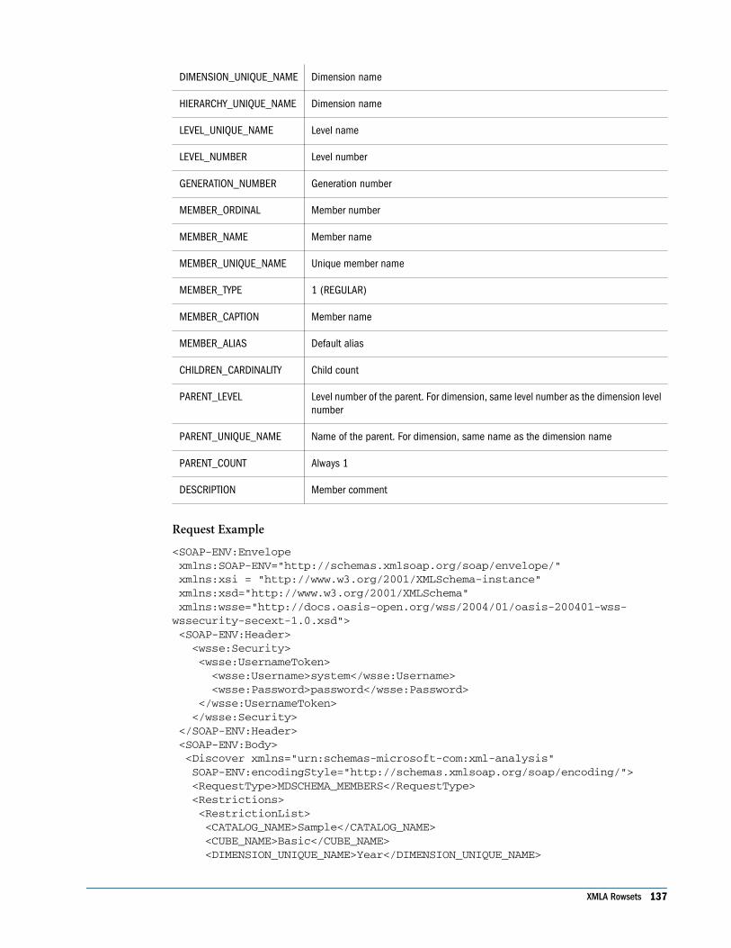
DIMENSION_UNIQUE_NAME Dimension name
HIERARCHY_UNIQUE_NAME Dimension name
LEVEL_UNIQUE_NAME Level name
LEVEL_NUMBER Level number
GENERATION_NUMBER Generation number
MEMBER_ORDINAL Member number
MEMBER_NAME Member name
MEMBER_UNIQUE_NAME Unique member name
MEMBER_TYPE 1 (REGULAR)
MEMBER_CAPTION Member name
MEMBER_ALIAS Default alias
CHILDREN_CARDINALITY Child count
PARENT_LEVEL Level number of the parent. For dimension, same level number as the dimension levelnumber
PARENT_UNIQUE_NAME Name of the parent. For dimension, same name as the dimension name
PARENT_COUNT Always 1
DESCRIPTION Member comment
Request Example
<SOAP-ENV:Envelope xmlns:SOAP-ENV="http://schemas.xmlsoap.org/soap/envelope/" xmlns:xsi = "http://www.w3.org/2001/XMLSchema-instance" xmlns:xsd="http://www.w3.org/2001/XMLSchema" xmlns:wsse="http://docs.oasis-open.org/wss/2004/01/oasis-200401-wss-wssecurity-secext-1.0.xsd"> <SOAP-ENV:Header> <wsse:Security> <wsse:UsernameToken> <wsse:Username>system</wsse:Username> <wsse:Password>password</wsse:Password> </wsse:UsernameToken> </wsse:Security> </SOAP-ENV:Header> <SOAP-ENV:Body> <Discover xmlns="urn:schemas-microsoft-com:xml-analysis" SOAP-ENV:encodingStyle="http://schemas.xmlsoap.org/soap/encoding/"> <RequestType>MDSCHEMA_MEMBERS</RequestType> <Restrictions> <RestrictionList> <CATALOG_NAME>Sample</CATALOG_NAME> <CUBE_NAME>Basic</CUBE_NAME> <DIMENSION_UNIQUE_NAME>Year</DIMENSION_UNIQUE_NAME>
XMLA Rowsets 137
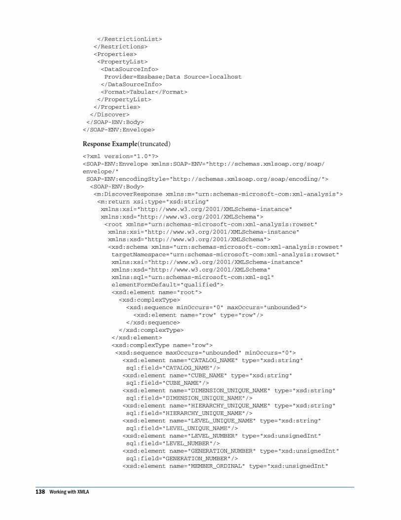
</RestrictionList> </Restrictions> <Properties> <PropertyList> <DataSourceInfo> Provider=Essbase;Data Source=localhost </DataSourceInfo> <Format>Tabular</Format> </PropertyList> </Properties> </Discover> </SOAP-ENV:Body></SOAP-ENV:Envelope>
Response Example(truncated)
<?xml version="1.0"?><SOAP-ENV:Envelope xmlns:SOAP-ENV="http://schemas.xmlsoap.org/soap/envelope/" SOAP-ENV:encodingStyle="http://schemas.xmlsoap.org/soap/encoding/"> <SOAP-ENV:Body> <m:DiscoverResponse xmlns:m="urn:schemas-microsoft-com:xml-analysis"> <m:return xsi:type="xsd:string" xmlns:xsi="http://www.w3.org/2001/XMLSchema-instance" xmlns:xsd="http://www.w3.org/2001/XMLSchema"> <root xmlns="urn:schemas-microsoft-com:xml-analysis:rowset" xmlns:xsi="http://www.w3.org/2001/XMLSchema-instance" xmlns:xsd="http://www.w3.org/2001/XMLSchema"> <xsd:schema xmlns="urn:schemas-microsoft-com:xml-analysis:rowset" targetNamespace="urn:schemas-microsoft-com:xml-analysis:rowset" xmlns:xsi="http://www.w3.org/2001/XMLSchema-instance" xmlns:xsd="http://www.w3.org/2001/XMLSchema" xmlns:sql="urn:schemas-microsoft-com:xml-sql" elementFormDefault="qualified"> <xsd:element name="root"> <xsd:complexType> <xsd:sequence minOccurs="0" maxOccurs="unbounded"> <xsd:element name="row" type="row"/> </xsd:sequence> </xsd:complexType> </xsd:element> <xsd:complexType name="row"> <xsd:sequence maxOccurs="unbounded" minOccurs="0"> <xsd:element name="CATALOG_NAME" type="xsd:string" sql:field="CATALOG_NAME"/> <xsd:element name="CUBE_NAME" type="xsd:string" sql:field="CUBE_NAME"/> <xsd:element name="DIMENSION_UNIQUE_NAME" type="xsd:string" sql:field="DIMENSION_UNIQUE_NAME"/> <xsd:element name="HIERARCHY_UNIQUE_NAME" type="xsd:string" sql:field="HIERARCHY_UNIQUE_NAME"/> <xsd:element name="LEVEL_UNIQUE_NAME" type="xsd:string" sql:field="LEVEL_UNIQUE_NAME"/> <xsd:element name="LEVEL_NUMBER" type="xsd:unsignedInt" sql:field="LEVEL_NUMBER"/> <xsd:element name="GENERATION_NUMBER" type="xsd:unsignedInt" sql:field="GENERATION_NUMBER"/> <xsd:element name="MEMBER_ORDINAL" type="xsd:unsignedInt"
138 Working with XMLA

sql:field="MEMBER_ORDINAL"/> <xsd:element name="MEMBER_NAME" type="xsd:string" sql:field="MEMBER_NAME"/> <xsd:element name="MEMBER_UNIQUE_NAME" type="xsd:string" sql:field="MEMBER_UNIQUE_NAME"/> <xsd:element name="MEMBER_TYPE" type="xsd:int" sql:field="MEMBER_TYPE"/> <xsd:element name="MEMBER_CAPTION" type="xsd:string" sql:field="MEMBER_CAPTION"/> <xsd:element name="MEMBER_ALIAS" type="xsd:string" sql:field="MEMBER_ALIAS" minOccurs="0"/> <xsd:element name="CHILDREN_CARDINALITY" type="xsd:unsignedInt" sql:field="CHILDREN_CARDINALITY"/> <xsd:element name="PARENT_LEVEL" type="xsd:unsignedInt" sql:field="PARENT_LEVEL"/> <xsd:element name="PARENT_UNIQUE_NAME" type="xsd:string" sql:field="PARENT_UNIQUE_NAME"/> <xsd:element name="PARENT_COUNT" type="xsd:unsignedInt" sql:field="PARENT_COUNT"/> <xsd:element name="DESCRIPTION" type="xsd:string" sql:field="DESCRIPTION" minOccurs="0" /> </xsd:sequence> </xsd:complexType> </xsd:schema> <row> <CATALOG_NAME>Sample</CATALOG_NAME> <CUBE_NAME>Sample.Basic</CUBE_NAME> <DIMENSION_UNIQUE_NAME>[Year]</DIMENSION_UNIQUE_NAME> <HIERARCHY_UNIQUE_NAME>[Year]</HIERARCHY_UNIQUE_NAME> <LEVEL_UNIQUE_NAME>[Year].Levels(2)</LEVEL_UNIQUE_NAME> <LEVEL_NUMBER>2</LEVEL_NUMBER> <GENERATION_NUMBER>1</GENERATION_NUMBER> <MEMBER_ORDINAL>1</MEMBER_ORDINAL> <MEMBER_NAME>Jan</MEMBER_NAME> <MEMBER_UNIQUE_NAME>[Jan]</MEMBER_UNIQUE_NAME> <MEMBER_TYPE>1</MEMBER_TYPE> <MEMBER_CAPTION>Jan</MEMBER_CAPTION> <CHILDREN_CARDINALITY>0</CHILDREN_CARDINALITY> <PARENT_LEVEL>1</PARENT_LEVEL> <PARENT_UNIQUE_NAME>[Qtr1]</PARENT_UNIQUE_NAME> <PARENT_COUNT>1</PARENT_COUNT> </row> < ................More Rows............. > </root> </m:return> </m:DiscoverResponse> </SOAP-ENV:Body> </SOAP-ENV:Envelope>
MDSCHEMA_PROPERTIES RowsetThe PROPERTIES rowset contains information about the available properties for each level ofthe dimension, assuming that each level defines a class of members. The properties of allmembers in this class are the same. For a data store that does not support named levels, a dummy
XMLA Rowsets 139

level includes all members in the dimension. The name of this level is the same as the name ofthe dimension.
The default sort order: PROPERTY_TYPE, CATALOG_NAME, SCHEMA_NAME,CUBE_NAME, DIMENSION_UNIQUE_NAME, HIERARCHY_UNIQUE_NAME, andLEVEL_UNIQUE_NAME.
GUID: MDSCHEMA_PROPERTIES
The following table describes the rowset structure.
Column name Essbase Mapping
CATALOG_NAME Application name
CUBE_NAME Database name
HIERARCHY_UNIQUE_NAME Dimension name
LEVEL_UNIQUE_NAME Dimension name
PROPERTY_TYPE 1 (MDPROP_MEMBER)
PROPERTY_NAME One of the following:
● For attribute dimension, the name of the dimension is the name ofthe property
● For UDA, the UDA name
● For aliases, the alias name
PROPERTY_CAPTION One of the following:
● For attribute dimensions, the attribute dimension name
● For UDA, the UDA name
● For aliases, the alias name
DATA_TYPE 1 (double) – attribute dimension
2 (boolean) – attribute dimension
3 (string) – attribute dimension, UDA or alias
4 (integer) – attribute dimension
CHARACTER_MAXIMUM_LENGTH 80 (for UDA or an attribute dimension)
30 (for alias)
CHARACTER_OCTET_LENGTH 320 (for UDA or an attribute dimension)
120 (for alias)
PROPERTY_CONTENT_TYPE 0 (MD_PROPTYPE_REGULAR)
SQL_COLUMN_NAME One of the following:
● For attribute dimensions, the attribute dimension name
● For UDA, the UDA name
● For aliases, the alias name
140 Working with XMLA

PROPERTY_ORIGIN 1 (MD_USER_DEFINED)
PROPERTY_ATTRIBUTE_HIERARCHY_NAME ● For attribute dimensions, the attribute dimension name
PROPERTY_CARDINALITY ONE (for UDA and aliases)
MANY (for attribute dimension)
PROPERTY_IS_VISIBLE True
Request Example
<SOAP-ENV:Envelope xmlns:SOAP-ENV="http://schemas.xmlsoap.org/soap/envelope/" xmlns:xsi = "http://www.w3.org/2001/XMLSchema-instance" xmlns:xsd="http://www.w3.org/2001/XMLSchema"> <SOAP-ENV:Body> <Discover xmlns="urn:schemas-microsoft-com:xml-analysis" SOAP-ENV:encodingStyle="http://schemas.xmlsoap.org/soap/encoding/"> <RequestType>MDSCHEMA_PROPERTIES</RequestType> <Restrictions> <RestrictionList> <CATALOG_NAME>Sample</CATALOG_NAME> <CUBE_NAME>Basic</CUBE_NAME> <DIMENSION_UNIQUE_NAME>Product</DIMENSION_UNIQUE_NAME> <LEVEL_UNIQUE_NAME>SKU</LEVEL_UNIQUE_NAME> </RestrictionList> </Restrictions> <Properties> <PropertyList> <DataSourceInfo> Provider=Essbase;Data Source=localhost </DataSourceInfo> <Format>Tabular</Format> </PropertyList> </Properties> </Discover> </SOAP-ENV:Body></SOAP-ENV:Envelope>
Response Example(truncated)
<?xml version="1.0"?><SOAP-ENV:Envelope xmlns:SOAP-ENV="http://schemas.xmlsoap.org/soap/envelope/" SOAP-ENV:encodingStyle="http://schemas.xmlsoap.org/soap/encoding/"> <SOAP-ENV:Body> <m:DiscoverResponse xmlns:m="urn:schemas-microsoft-com:xml-analysis"> <m:return xsi:type="xsd:string" xmlns:xsi="http://www.w3.org/2001/XMLSchema-instance" xmlns:xsd="http://www.w3.org/2001/XMLSchema"> <root xmlns="urn:schemas-microsoft-com:xml-analysis:rowset" xmlns:xsi="http://www.w3.org/2001/XMLSchema-instance" xmlns:xsd="http://www.w3.org/2001/XMLSchema"> <xsd:schema xmlns="urn:schemas-microsoft-com:xml-analysis:rowset" targetNamespace="urn:schemas-microsoft-com:xml-analysis:rowset" xmlns:xsi="http://www.w3.org/2001/XMLSchema-instance" xmlns:xsd="http://www.w3.org/2001/XMLSchema"
XMLA Rowsets 141

xmlns:sql="urn:schemas-microsoft-com:xml-sql" elementFormDefault="qualified"> <xsd:element name="root"> <xsd:complexType> <xsd:sequence minOccurs="0" maxOccurs="unbounded"> <xsd:element name="row" type="row"/> </xsd:sequence> </xsd:complexType> </xsd:element> <xsd:complexType name="row"> <xsd:sequence maxOccurs="unbounded" minOccurs="0"> <xsd:element name="CATALOG_NAME" type="xsd:string" sql:field="CATALOG_NAME"/> <xsd:element name="CUBE_NAME" type="xsd:string" sql:field="CUBE_NAME"/> <xsd:element name="DIMENSION_UNIQUE_NAME" type="xsd:string" sql:field="DIMENSION_UNIQUE_NAME"/> <xsd:element name="HIERARCHY_UNIQUE_NAME" type="xsd:string" sql:field="HIERARCHY_UNIQUE_NAME"/> <xsd:element name="LEVEL_UNIQUE_NAME" type="xsd:string" sql:field="LEVEL_UNIQUE_NAME" minOccurs ="0"/> <xsd:element name="MEMBER_UNIQUE_NAME" type="xsd:string" sql:field="MEMBER_UNIQUE_NAME" minOccurs ="0"/> <xsd:element name="PROPERTY_TYPE" type="xsd:short" sql:field="PROPERTY_TYPE" minOccurs ="0"/> <xsd:element name="PROPERTY_NAME" type="xsd:string" sql:field="PROPERTY_NAME" minOccurs ="0"/> <xsd:element name="PROPERTY_CAPTION" type="xsd:string" sql:field="PROPERTY_CAPTION" minOccurs ="0"/> <xsd:element name="DATA_TYPE" type="xsd:unsignedShort" sql:field="DATA_TYPE" minOccurs ="0"/> <xsd:element name="CHARACTER_MAXIMUM_LENGTH" type="xsd:unsignedInt" sql:field="CHARACTER_MAXIMUM_LENGTH" minOccurs ="0"/> <xsd:element name="CHARACTER_OCTET_LENGTH" type="xsd:unsignedInt" sql:field="CHARACTER_OCTET_LENGTH" minOccurs ="0"/> <xsd:element name="NUMERIC_PRECISION" type="xsd:unsignedShort" sql:field="NUMERIC_PRECISION" minOccurs ="0"/> <xsd:element name="NUMERIC_SCALE" type="xsd:short" sql:field="NUMERIC_SCALE" minOccurs ="0"/> <xsd:element name="DESCRIPTION" type="xsd:string" sql:field="DESCRIPTION" minOccurs ="0"/> <xsd:element name="PROPERTY_CONTENT_TYPE" type="xsd:short" sql:field="PROPERTY_CONTENT_TYPE" minOccurs ="0"/> <xsd:element name="SQL_COLUMN_NAME" type="xsd:string" sql:field="SQL_COLUMN_NAME" minOccurs ="0"/> <xsd:element name="LANGUAGE" type="xsd:unsignedShort" sql:field="LANGUAGE" minOccurs ="0"/> <xsd:element name="PROPERTY_ORIGIN" type="xsd:unsignedShort" sql:field="PROPERTY_ORIGIN" minOccurs ="0"/> <xsd:element name="PROPERTY_ATTRIBUTE_HIERARCHY_NAME" type="xsd:string" sql:field="PROPERTY_ATTRIBUTE_HIERARCHY_NAME" minOccurs ="0"/> <xsd:element name="PROPERTY_CARDINALITY" type="xsd:string" sql:field="PROPERTY_CARDINALITY" minOccurs ="0"/> <xsd:element name="MIME_TYPE" type="xsd:string" sql:field="MIME_TYPE" minOccurs ="0"/>
142 Working with XMLA

<xsd:element name="PROPERTY_IS_VISIBLE" type="xsd:boolean" sql:field="PROPERTY_IS_VISIBLE" minOccurs ="0"/> </xsd:sequence> </xsd:complexType> </xsd:schema> <row> <CATALOG_NAME>Sample</CATALOG_NAME> <CUBE_NAME>Sample.Basic</CUBE_NAME> <DIMENSION_UNIQUE_NAME>[Product]</DIMENSION_UNIQUE_NAME> <HIERARCHY_UNIQUE_NAME>[Product]</HIERARCHY_UNIQUE_NAME> <LEVEL_UNIQUE_NAME>[Product]</LEVEL_UNIQUE_NAME> <PROPERTY_TYPE>1</PROPERTY_TYPE> <PROPERTY_NAME>Caffeinated</PROPERTY_NAME> <PROPERTY_CAPTION>Caffeinated</PROPERTY_CAPTION> <DATA_TYPE>2</DATA_TYPE> <PROPERTY_CONTENT_TYPE>0</PROPERTY_CONTENT_TYPE> <SQL_COLUMN_NAME>Caffeinated</SQL_COLUMN_NAME> <PROPERTY_ORIGIN>1</PROPERTY_ORIGIN> <PROPERTY_ATTRIBUTE_HIERARCHY_NAME>Caffeinated </PROPERTY_ATTRIBUTE_HIERARCHY_NAME> <PROPERTY_CARDINALITY>MANY</PROPERTY_CARDINALITY> <PROPERTY_IS_VISIBLE>true</PROPERTY_IS_VISIBLE> </row> < ................More Rows............. > </root> </m:return> </m:DiscoverResponse> </SOAP-ENV:Body></SOAP-ENV:Envelope>
MDSCHEMA_SETS RowsetThe SETS rowset contains information about the sets in a schema (or the catalog, if the providerdoes not support schemas).
GUID: MDSCHEMA_SETS
The following table describes the rowset structure.
Column name Essbase Mapping
CATALOG_NAME Application name
CUBE_NAME Database name
SET_NAME Name of the set
SCOPE Session
MDSCHEMA_LEVELS RowsetThe LEVELS rowset contains information about the levels available in a dimension.
GUID: MDSCHEMA_LEVELS
XMLA Rowsets 143
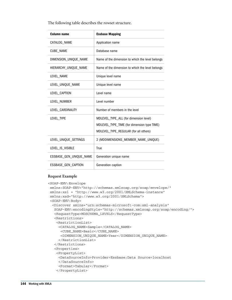
The following table describes the rowset structure.
Column name Essbase Mapping
CATALOG_NAME Application name
CUBE_NAME Database name
DIMENSION_UNIQUE_NAME Name of the dimension to which the level belongs
HIERARCHY_UNIQUE_NAME Name of the dimension to which the level belongs
LEVEL_NAME Unique level name
LEVEL_UNIQUE_NAME Unique level name
LEVEL_CAPTION Level name
LEVEL_NUMBER Level number
LEVEL_CARDINALITY Number of members in the level
LEVEL_TYPE MDLEVEL_TYPE_ALL (for dimension level)
MDLEVEL_TYPE_TIME (for dimension type TIME)
MDLEVEL_TYPE_REGULAR (for all others)
LEVEL_UNIQUE_SETTINGS 2 (MDDIMENSIONS_MEMBER_NAME_UNIQUE)
LEVEL_IS_VISIBLE True
ESSBASE_GEN_UNIQUE_NAME Generation unique name
ESSBASE_GEN_CAPTION Generation caption
Request Example
<SOAP-ENV:Envelope xmlns:SOAP-ENV="http://schemas.xmlsoap.org/soap/envelope/" xmlns:xsi = "http://www.w3.org/2001/XMLSchema-instance" xmlns:xsd="http://www.w3.org/2001/XMLSchema"> <SOAP-ENV:Body> <Discover xmlns="urn:schemas-microsoft-com:xml-analysis" SOAP-ENV:encodingStyle="http://schemas.xmlsoap.org/soap/encoding/"> <RequestType>MDSCHEMA_LEVELS</RequestType> <Restrictions> <RestrictionList> <CATALOG_NAME>Sample</CATALOG_NAME> <CUBE_NAME>Basic</CUBE_NAME> <DIMENSION_UNIQUE_NAME>Year</DIMENSION_UNIQUE_NAME> </RestrictionList> </Restrictions> <Properties> <PropertyList> <DataSourceInfo>Provider=Essbase;Data Source=localhost </DataSourceInfo> <Format>Tabular</Format> </PropertyList>
144 Working with XMLA

</Properties> </Discover> </SOAP-ENV:Body></SOAP-ENV:Envelope>
Response Example
<?xml version="1.0"?><SOAP-ENV:Envelope xmlns:SOAP-ENV="http://schemas.xmlsoap.org/soap/envelope/" SOAP-ENV:encodingStyle="http://schemas.xmlsoap.org/soap/encoding/"> <SOAP-ENV:Body> <m:DiscoverResponse xmlns:m="urn:schemas-microsoft-com:xml-analysis"> <m:return xsi:type="xsd:string" xmlns:xsi="http://www.w3.org/2001/XMLSchema-instance" xmlns:xsd="http://www.w3.org/2001/XMLSchema"> <root xmlns="urn:schemas-microsoft-com:xml-analysis:rowset" xmlns:xsi="http://www.w3.org/2001/XMLSchema-instance" xmlns:xsd="http://www.w3.org/2001/XMLSchema"> <xsd:schema xmlns="urn:schemas-microsoft-com:xml-analysis:rowset" targetNamespace="urn:schemas-microsoft-com:xml-analysis:rowset" xmlns:xsi="http://www.w3.org/2001/XMLSchema-instance" xmlns:xsd="http://www.w3.org/2001/XMLSchema" xmlns:sql="urn:schemas-microsoft-com:xml-sql" elementFormDefault="qualified"> <xsd:element name="root"> <xsd:complexType> <xsd:sequence minOccurs="0" maxOccurs="unbounded"> <xsd:element name="row" type="row"/> </xsd:sequence> </xsd:complexType> </xsd:element> <xsd:complexType name="row"> <xsd:sequence maxOccurs="unbounded" minOccurs="0"> <xsd:element name="CATALOG_NAME" type="xsd:string" sql:field="CATALOG_NAME"/> <xsd:element name="CUBE_NAME" type="xsd:string" sql:field="CUBE_NAME"/> <xsd:element name="DIMENSION_UNIQUE_NAME" type="xsd:string" sql:field="DIMENSION_UNIQUE_NAME"/> <xsd:element name="HIERARCHY_UNIQUE_NAME" type="xsd:string" sql:field="HIERARCHY_UNIQUE_NAME"/> <xsd:element name="LEVEL_NAME" type="xsd:string" sql:field="LEVEL_NAME"/> <xsd:element name="LEVEL_UNIQUE_NAME" type="xsd:string" sql:field="LEVEL_UNIQUE_NAME"/> <xsd:element name="LEVEL_CAPTION" type="xsd:string" sql:field="LEVEL_CAPTION"/> <xsd:element name="LEVEL_NUMBER" type="xsd:unsignedInt" sql:field="LEVEL_NUMBER"/> <xsd:element name="LEVEL_CARDINALITY" type="xsd:unsignedInt" sql:field="LEVEL_CARDINALITY"/> <xsd:element name="LEVEL_TYPE" type="xsd:int" sql:field="LEVEL_TYPE"/> <xsd:element name="LEVEL_UNIQUE_SETTINGS" type="xsd:int" sql:field="LEVEL_UNIQUE_SETTINGS"/> <xsd:element name="LEVEL_IS_VISIBLE" type="xsd:boolean" sql:field="LEVEL_IS_VISIBLE"/>
XMLA Rowsets 145

<xsd:element name="DESCRIPTION" type="xsd:string" sql:field="DESCRIPTION" minOccurs="0"/> <xsd:element name="ESSBASE_GEN_UNIQUE_NAME" type="xsd:string" sql:field="ESSBASE_GEN_UNIQUE_NAME"/> <xsd:element name="ESSBASE_GEN_CAPTION" type="xsd:string" sql:field="ESSBASE_GEN_CAPTION"/> </xsd:sequence> </xsd:complexType> </xsd:schema> <row> <CATALOG_NAME>Sample</CATALOG_NAME> <CUBE_NAME>Sample.Basic</CUBE_NAME> <DIMENSION_UNIQUE_NAME>[Year]</DIMENSION_UNIQUE_NAME> <HIERARCHY_UNIQUE_NAME>[Year]</HIERARCHY_UNIQUE_NAME> <LEVEL_NAME>[Year].Levels(2)</LEVEL_NAME> <LEVEL_UNIQUE_NAME>[Year].Levels(2)</LEVEL_UNIQUE_NAME> <LEVEL_CAPTION>[Year].Level 2</LEVEL_CAPTION> <LEVEL_NUMBER>2</LEVEL_NUMBER> <LEVEL_CARDINALITY>12</LEVEL_CARDINALITY> <LEVEL_TYPE>4</LEVEL_TYPE> <LEVEL_UNIQUE_SETTINGS>2</LEVEL_UNIQUE_SETTINGS> <LEVEL_IS_VISIBLE>true</LEVEL_IS_VISIBLE> <ESSBASE_GEN_UNIQUE_NAME>[Year].[Months]</ESSBASE_GEN_UNIQUE_NAME> <ESSBASE_GEN_CAPTION>[Year].Months</ESSBASE_GEN_CAPTION> </row> < ................More Rows............. > </root> </m:return> </m:DiscoverResponse> </SOAP-ENV:Body></SOAP-ENV:Envelope>
DISCOVER_SCHEMA_ROWSETS RowsetGUID: DISCOVER_SCHEMA_ROWSETS
The following table describes the rowset structure.
Column name Essbase Mapping
SchemaName The name of the schema/request. This returns the values in the RequestTypes enumeration, plusany additional types supported by the provider. The provider defines rowset structures for theadditional types.
Restrictions List of restrictions allowed
Description Description of the schema
DISCOVER_DATASOURCES RowsetGUID: DISCOVER_DATASOURCES
The following table describes the rowset structure.
146 Working with XMLA

Column name Essbase Mapping
DataSourceName Name of the data source
DataSourceDescription Description of the data source
DataSourceInfo Provider=Essbase Data Source= name of the Analytic Server
ProviderName XMLA for Essbase
ProviderType MDP
AuthenticationMode Authenticated
DISCOVER_PROPERTIES RowsetGUID: DISCOVER_PROPERTIES
The rowset structure is described in the following table.
Column name Essbase Mapping
PropertyName Name of the property
PropertyDescription Description of the property
PropertyType XML data type of the property.
PropertyAccessType Access for the property. The value can be Read, Write, or ReadWrite
IsRequired True if a property is required, false if it is not required
Value Current value of the property
Request Example
<SOAP-ENV:Envelope xmlns:SOAP-ENV="http://schemas.xmlsoap.org/soap/envelope/" xmlns:xsi = "http://www.w3.org/2001/XMLSchema-instance" xmlns:xsd="http://www.w3.org/2001/XMLSchema"> <SOAP-ENV:Body> <Discover xmlns="urn:schemas-microsoft-com:xml-analysis" SOAP-ENV:encodingStyle="http://schemas.xmlsoap.org/soap/encoding/"> <RequestType>DISCOVER_PROPERTIES</RequestType> <Restrictions> <RestrictionList></RestrictionList> </Restrictions> <Properties> <PropertyList> <DataSourceInfo>Provider=Essbase;Data Source=localhost </DataSourceInfo> <Format>Tabular</Format> </PropertyList> </Properties> </Discover>
XMLA Rowsets 147

</SOAP-ENV:Body></SOAP-ENV:Envelope>
Response Example
<?xml version="1.0"?><SOAP-ENV:Envelope xmlns:SOAP-ENV="http://schemas.xmlsoap.org/soap/envelope/" SOAP-ENV:encodingStyle="http://schemas.xmlsoap.org/soap/encoding/"> <SOAP-ENV:Body> <m:DiscoverResponse xmlns:m="urn:schemas-microsoft-com:xml-analysis"> <m:return xsi:type="xsd:string" xmlns:xsi="http://www.w3.org/2001/XMLSchema-instance" xmlns:xsd="http://www.w3.org/2001/XMLSchema"> <root xmlns="urn:schemas-microsoft-com:xml-analysis:rowset" xmlns:xsi="http://www.w3.org/2001/XMLSchema-instance" xmlns:xsd="http://www.w3.org/2001/XMLSchema"> <xsd:schema xmlns="urn:schemas-microsoft-com:xml-analysis:rowset" targetNamespace="urn:schemas-microsoft-com:xml-analysis:rowset" xmlns:xsi="http://www.w3.org/2001/XMLSchema-instance" xmlns:xsd="http://www.w3.org/2001/XMLSchema" xmlns:sql="urn:schemas-microsoft-com:xml-sql" elementFormDefault="qualified"> <xsd:element name="root"> <xsd:complexType> <xsd:sequence minOccurs="0" maxOccurs="unbounded"> <xsd:element name="row" type="row"/> </xsd:sequence> </xsd:complexType> </xsd:element> <xsd:complexType name="row"> <xsd:sequence maxOccurs="unbounded" minOccurs="0"> <xsd:element name="PropertyName" type="xsd:string" sql:field="PropertyName"/> <xsd:element name="PropertyDescription" type="xsd:string" sql:field="PropertyDescription"/> <xsd:element name="PropertyType" type="xsd:string" sql:field="PropertyType"/> <xsd:element name="PropertyAccessType" type="xsd:string" sql:field="PropertyAccessType"/> <xsd:element name="IsRequired" type="xsd:boolean" sql:field="IsRequired"/> <xsd:element name="Value" type="xsd:string" sql:field="Value"/> </xsd:sequence> </xsd:complexType> </xsd:schema> <row> <PropertyName>ProviderName</PropertyName> <PropertyDescription>The name of the Analytic Services Provider </PropertyDescription> <PropertyType>string</PropertyType> <PropertyAccessType>Read</PropertyAccessType> <IsRequired>false</IsRequired> <Value>Analytic Services XML for Analysis Provider</Value> </row> < ................More Rows............. > </root>
148 Working with XMLA
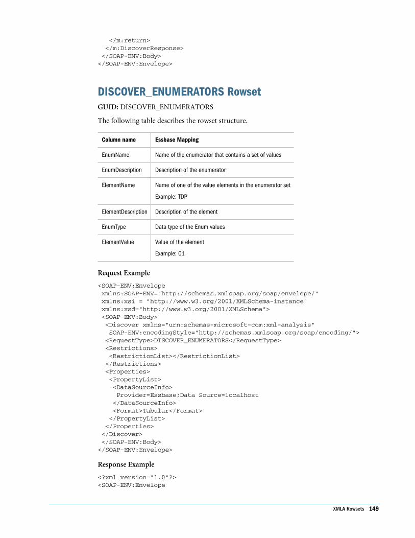
</m:return> </m:DiscoverResponse> </SOAP-ENV:Body></SOAP-ENV:Envelope>
DISCOVER_ENUMERATORS RowsetGUID: DISCOVER_ENUMERATORS
The following table describes the rowset structure.
Column name Essbase Mapping
EnumName Name of the enumerator that contains a set of values
EnumDescription Description of the enumerator
ElementName Name of one of the value elements in the enumerator set
Example: TDP
ElementDescription Description of the element
EnumType Data type of the Enum values
ElementValue Value of the element
Example: 01
Request Example
<SOAP-ENV:Envelope xmlns:SOAP-ENV="http://schemas.xmlsoap.org/soap/envelope/" xmlns:xsi = "http://www.w3.org/2001/XMLSchema-instance" xmlns:xsd="http://www.w3.org/2001/XMLSchema"> <SOAP-ENV:Body> <Discover xmlns="urn:schemas-microsoft-com:xml-analysis" SOAP-ENV:encodingStyle="http://schemas.xmlsoap.org/soap/encoding/"> <RequestType>DISCOVER_ENUMERATORS</RequestType> <Restrictions> <RestrictionList></RestrictionList> </Restrictions> <Properties> <PropertyList> <DataSourceInfo> Provider=Essbase;Data Source=localhost </DataSourceInfo> <Format>Tabular</Format> </PropertyList> </Properties> </Discover> </SOAP-ENV:Body></SOAP-ENV:Envelope>
Response Example
<?xml version="1.0"?><SOAP-ENV:Envelope
XMLA Rowsets 149

xmlns:SOAP-ENV="http://schemas.xmlsoap.org/soap/envelope/" SOAP-ENV:encodingStyle="http://schemas.xmlsoap.org/soap/encoding/"> <SOAP-ENV:Body> <m:DiscoverResponse xmlns:m="urn:schemas-microsoft-com:xml-analysis"> <m:return xsi:type="xsd:string" xmlns:xsi="http://www.w3.org/2001/XMLSchema-instance" xmlns:xsd="http://www.w3.org/2001/XMLSchema"> <root xmlns="urn:schemas-microsoft-com:xml-analysis:rowset" xmlns:xsi="http://www.w3.org/2001/XMLSchema-instance" xmlns:xsd="http://www.w3.org/2001/XMLSchema"> <xsd:schema xmlns="urn:schemas-microsoft-com:xml-analysis:rowset" targetNamespace="urn:schemas-microsoft-com:xml-analysis:rowset" xmlns:xsi="http://www.w3.org/2001/XMLSchema-instance" xmlns:xsd="http://www.w3.org/2001/XMLSchema" xmlns:sql="urn:schemas-microsoft-com:xml-sql" elementFormDefault="qualified"> <xsd:element name="root"> <xsd:complexType> <xsd:sequence minOccurs="0" maxOccurs="unbounded"> <xsd:element name="row" type="row"/> </xsd:sequence> </xsd:complexType> </xsd:element> <xsd:complexType name="row"> <xsd:sequence maxOccurs="unbounded" minOccurs="0"> <xsd:element name="EnumName" type="xsd:string" sql:field="EnumName"/> <xsd:element name="EnumDescription" type="xsd:string" sql:field="EnumDescription" minOccurs="0"/> <xsd:element name="ElementName" type="xsd:string" sql:field="ElementName"/> <xsd:element name="ElementDescription" type="xsd:string" sql:field="ElementDescription" minOccurs="0"/> <xsd:element name="ElementValue" type="xsd:string" sql:field="ElementValue" minOccurs="0"/> <xsd:element name="EnumType" type="xsd:string" sql:field="EnumType"/> </xsd:sequence> </xsd:complexType> </xsd:schema> <row> <EnumName>ProviderType</EnumName> <ElementName>TDP</ElementName> <EnumType>string</EnumType> </row> < ................More Rows............. > </root> </m:return> </m:DiscoverResponse> </SOAP-ENV:Body></SOAP-ENV:Envelope>
DISCOVER_KEYWORDS RowsetGUID: DISCOVER_KEYWORDS
150 Working with XMLA
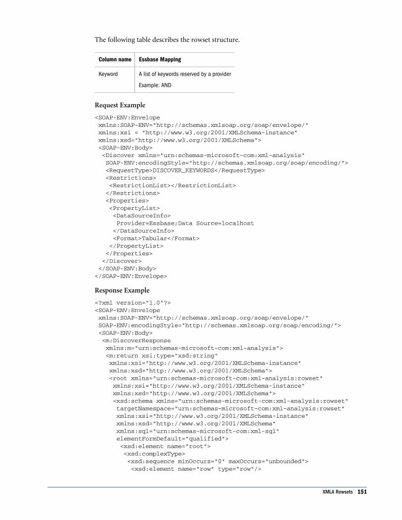
The following table describes the rowset structure.
Column name Essbase Mapping
Keyword A list of keywords reserved by a provider
Example: AND
Request Example
<SOAP-ENV:Envelope xmlns:SOAP-ENV="http://schemas.xmlsoap.org/soap/envelope/" xmlns:xsi = "http://www.w3.org/2001/XMLSchema-instance" xmlns:xsd="http://www.w3.org/2001/XMLSchema"> <SOAP-ENV:Body> <Discover xmlns="urn:schemas-microsoft-com:xml-analysis" SOAP-ENV:encodingStyle="http://schemas.xmlsoap.org/soap/encoding/"> <RequestType>DISCOVER_KEYWORDS</RequestType> <Restrictions> <RestrictionList></RestrictionList> </Restrictions> <Properties> <PropertyList> <DataSourceInfo> Provider=Essbase;Data Source=localhost </DataSourceInfo> <Format>Tabular</Format> </PropertyList> </Properties> </Discover> </SOAP-ENV:Body></SOAP-ENV:Envelope>
Response Example
<?xml version="1.0"?><SOAP-ENV:Envelope xmlns:SOAP-ENV="http://schemas.xmlsoap.org/soap/envelope/" SOAP-ENV:encodingStyle="http://schemas.xmlsoap.org/soap/encoding/"> <SOAP-ENV:Body> <m:DiscoverResponse xmlns:m="urn:schemas-microsoft-com:xml-analysis"> <m:return xsi:type="xsd:string" xmlns:xsi="http://www.w3.org/2001/XMLSchema-instance" xmlns:xsd="http://www.w3.org/2001/XMLSchema"> <root xmlns="urn:schemas-microsoft-com:xml-analysis:rowset" xmlns:xsi="http://www.w3.org/2001/XMLSchema-instance" xmlns:xsd="http://www.w3.org/2001/XMLSchema"> <xsd:schema xmlns="urn:schemas-microsoft-com:xml-analysis:rowset" targetNamespace="urn:schemas-microsoft-com:xml-analysis:rowset" xmlns:xsi="http://www.w3.org/2001/XMLSchema-instance" xmlns:xsd="http://www.w3.org/2001/XMLSchema" xmlns:sql="urn:schemas-microsoft-com:xml-sql" elementFormDefault="qualified"> <xsd:element name="root"> <xsd:complexType> <xsd:sequence minOccurs="0" maxOccurs="unbounded"> <xsd:element name="row" type="row"/>
XMLA Rowsets 151

</xsd:sequence> </xsd:complexType> </xsd:element> <xsd:complexType name="row"> <xsd:sequence maxOccurs="unbounded" minOccurs="0"> <xsd:element name="Keyword" type="xsd:string" sql:field="Keyword"/> </xsd:sequence> </xsd:complexType> </xsd:schema> <row><Keyword>aggregate</Keyword></row> <row><Keyword>ancestors</Keyword></row> < ................More Rows............. > </root> </m:return> </m:DiscoverResponse> </SOAP-ENV:Body></SOAP-ENV:Envelope>
DISCOVER_LITERALS RowsetGUID: DISCOVER_LITERALS
The following table describes the rowset structure.
Column name Essbase Mapping
LiteralName Name of the literal described in the row
Example: DBLITERAL_LIKE_PERCENT
LiteralValue Contains the literal value
Example, if LiteralName is DBLITERAL_LIKE_PERCENT and the percent character (%) isused to match zero or more characters in a LIKE clause, this column’s value would be“%.”
LiteralInvalidChars Characters, in the literal, that are not valid
Example: If table names can contain anything other than a numeric character, this stringwould be “0123456789”
LiteralInvalidStartingChars Characters that are not valid as the first character of the literal. If the literal can start withany valid character, this is null.
LiteralMaxLength Maximum number of characters in the literal. If there is no maximum or the maximum isunknown, the value is -1.
Flattened Rowset ExamplesFlattening a rowset is a way to present multidimensional data in a grid. This two-dimensional,tabular presentation of data can facilitate understanding of the output of a multidimensionalXMLA request.
152 Working with XMLA

MDX ExamplesThe following examples illustrate flattened rowsets as MDX queries and results. MDX is usedfor ease of presentation; however, the example queries are intended to be considered in termsof XMLA SOAP requests. Remember that in XMLA, level 0 represents a dimension, rather thana leaf member, as in MDX. Therefore, although these examples are in MDX, the levels arereversed as if they were in XMLA.
Example 1The following query requests all members of level 1.
SELECT NON EMPTY {[Profit]} ON COLUMNS, NON EMPTY [Product].Levels(1).ALLMEMBERS ON ROWS FROM Sample.Basic
This query has the following result:
[Product].[Family].[MEMBER_CAPTION] [Profit]
100 30468
200 27954
300 25799
400 21301
Diet 28826
Example 2The following query requests a maximum of two levels. The flattening of rowsets includes level1 in this request for levels(2). When using flattened rowsets, if you query for level N, levels 1through N are returned.
SELECT NON EMPTY {[Profit] } ON COLUMNS,NON EMPTY [Product].Levels(2).ALLMEMBERS ON ROWSFROM Sample.Basic
This query has the following result (truncated):
[Product].[Family].[MEMBER_CAPTION] [Product].[SKU].[MEMBER_CAPTION] [Profit]
100 100–10 22777
100 100–20 5708
100 100–30 1983
200 200–10 7201
200 200–20 12025
Flattened Rowset Examples 153

200 200–30 4636
200 200–40 4092
... ... ...
Example 3The following query builds on the previous, and also asks for the result set to include the memberunique name and level number properties for the set of levels 1 through N, where N=2. Eachmember and each property is allotted a row.
SELECT NON EMPTY {[Profit]} ON COLUMNS, NON EMPTY [Product].Levels(2).ALLMEMBERS DIMENSION PROPERTIES MEMBER_UNIQUE_NAME, LEVEL_NUMBER ON ROWS FROM Sample.Basic
This query has the following result (truncated):
[Product]. [Family].[MEMBER_ UNIQUE_NAME]
[Product]. [Family].LEVEL_ NUMBER
[Product]. [SKU].[MEMBER_ UNIQUE_NAME]
[Product]. [SKU].LEVEL_ NUMBER
[Profit]
[100] 1 [100–10] 2 22777
[100] 1 [100–20] 2 5708
[100] 1 [100–30] 2 1983
[200] 1 [200–10] 2 7201
[200] 1 [200–20] 2 12025
[200] 1 [200–30] 2 4636
[200] 1 [200–40] 2 4092
[300] 1 [300–10] 2 12195
[300] 1 [300–20] 2 2511
[300] 1 [300–30] 2 2511
... ... ... ... ...
Example 4By implementing CrossJoin in a flattened rowsets query, you can use multiple dimensions (atleast two). In this example, Market and Product dimensions are requested. For each dimension,the same logic as in previous examples applies: Each dimension, level, and property is allottedone column (in this case, one level and one property are requested).
SELECT NON EMPTY {[Profit] } ON COLUMNS, NON EMPTY Crossjoin ([Market].Levels(1).AllMembers,[Product].Levels
154 Working with XMLA
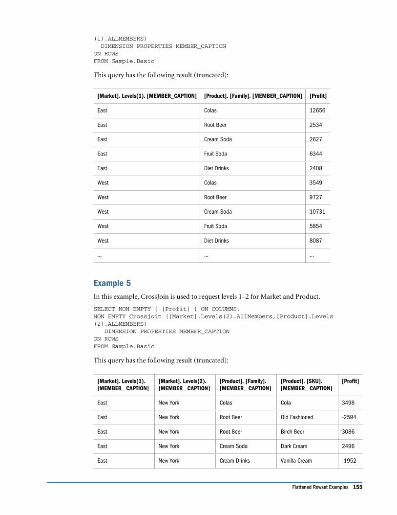
(1).ALLMEMBERS) DIMENSION PROPERTIES MEMBER_CAPTION ON ROWS FROM Sample.Basic
This query has the following result (truncated):
[Market]. Levels(1). [MEMBER_CAPTION] [Product]. [Family]. [MEMBER_CAPTION] [Profit]
East Colas 12656
East Root Beer 2534
East Cream Soda 2627
East Fruit Soda 6344
East Diet Drinks 2408
West Colas 3549
West Root Beer 9727
West Cream Soda 10731
West Fruit Soda 5854
West Diet Drinks 8087
... ... ...
Example 5In this example, CrossJoin is used to request levels 1–2 for Market and Product.
SELECT NON EMPTY { [Profit] } ON COLUMNS,NON EMPTY Crossjoin ([Market].Levels(2).AllMembers,[Product].Levels(2).ALLMEMBERS) DIMENSION PROPERTIES MEMBER_CAPTION ON ROWS FROM Sample.Basic
This query has the following result (truncated):
[Market]. Levels(1).[MEMBER_ CAPTION]
[Market]. Levels(2).[MEMBER_ CAPTION]
[Product]. [Family].[MEMBER_ CAPTION]
[Product]. [SKU].[MEMBER_ CAPTION]
[Profit]
East New York Colas Cola 3498
East New York Root Beer Old Fashioned -2594
East New York Root Beer Birch Beer 3086
East New York Cream Soda Dark Cream 2496
East New York Cream Drinks Vanilla Cream -1952
Flattened Rowset Examples 155

East New York Fruit Soda Grape 1329
East New York Fruit Soda Orange 1388
East New York Fruit Soda Strawberry 951
... ... ... ... ...
Example 6The following example uses CrossJoin to represent multiple dimensions, requests a differentnumber of levels for each dimension, and requests multiple properties.
SELECT NON EMPTY { [Profit] } ON COLUMNS,NON EMPTY Crossjoin ([Market].Levels(1).AllMembers,[Product].Levels(2).ALLMEMBERS) DIMENSION PROPERTIES MEMBER_CAPTION, LEVEL_NUMBER ON ROWS FROM Sample.Basic
This query has the following result (truncated):
[Market].Levels(1).[MEMBER_CAPTION]
[Market].Levels(1).[LEVEL_NUMBER]
[Product].[Family].[MEMBER_CAPTION]
[Market].Levels(1).[LEVEL_NUMBER]
[Product].[SKU].[MEMBER_CAPTION]
[Market].Levels(1).[LEVEL_NUMBER]
[Profit]
East 1 Colas 1 Cola 2 11129
East 1 Colas 1 Diet Cola 2 1114
East 1 Colas 1 Caffeine FreeCola
2 413
East 1 Root Beer 1 Old Fashioned 2 -2540
East 1 Root Beer 1 Diet Root Beer 2 982
East 1 Root Beer 1 Birch Beer 2 4092
East 1 Cream Soda 1 Dark Cream 2 3233
East 1 Cream Soda 1 Vanilla Cream 2 -918
... ... ... ... ... ... ...
Example 7The following example uses multiple, nested CrossJoins.
SELECT NON EMPTY { [Profit] } ON COLUMNS,NON EMPTY {CROSSJOIN ( CROSSJOIN( [Market].Levels(1).ALLMEMBERS, [Product].[Family].ALLMEMBERS
156 Working with XMLA

), [Year].Levels(1).ALLMEMBERS ) } DIMENSION PROPERTIES MEMBER_CAPTION ON ROWS FROM Sample.Basic
This query has the following result (truncated):
[Market]. Levels(1).[MEMBER_ CAPTION]
[Product]. [Family]. [MEMBER_CAPTION]
[Year]. Levels(1). [MEMBER_CAPTION]
[Profit]
East Colas Qtr1 2747
East Colas Qtr2 3352
East Colas Qtr3 3740
East Colas Qtr4 2817
East Root Beer Qtr1 562
East Root Beer Qtr2 610
East Root Beer Qtr3 372
East Root Beer Qtr4 990
... ... ... ...
XMLA ExamplesThe following examples illustrate an XMLA response and request.
This is an example of a flattened rowset request. To flatten the result, you must use Tabularformat in the PropertyList element, as shown in the example.
<SOAP-ENV:Envelope xmlns:SOAP-ENV="http://schemas.xmlsoap.org/soap/envelope/" xmlns:xsi = "http://www.w3.org/2001/XMLSchema-instance" xmlns:xsd="http://www.w3.org/2001/XMLSchema"> <SOAP-ENV:Body> <Execute xmlns="urn:schemas-microsoft-com:xml-analysis" SOAP-ENV:encodingStyle="http://schemas.xmlsoap.org/soap/encoding/"> <Command> <Statement> WITH MEMBER [Year].[calctest] AS '4' SELECT NON EMPTY { [Profit] } ON COLUMNS, NON EMPTY {[Year].ALLMEMBERS } ON ROWS FROM Sample.Basic </Statement> </Command> <Properties> <PropertyList> <DataSourceInfo>Provider=Essbase;Data Source=localhost </DataSourceInfo> <Catalog>Sample</Catalog>
Flattened Rowset Examples 157

<Format>Tabular</Format> <AxisFormat>TupleFormat</AxisFormat> </PropertyList> </Properties> </Execute> </SOAP-ENV:Body></SOAP-ENV:Envelope>
An example of a flattened rowset response:
<?xml version="1.0"?><SOAP-ENV:Envelope xmlns:SOAP-ENV="http://schemas.xmlsoap.org/soap/envelope/" SOAP-ENV:encodingStyle="http://schemas.xmlsoap.org/soap/encoding/"> <SOAP-ENV:Body> <m:ExecuteResponse xmlns:m="urn:schemas-microsoft-com:xml-analysis"> <m:return SOAP-ENV:encodingStyle="http://schemas.xmlsoap.org/soap/encoding/"> <root xmlns="urn:schemas-microsoft-com:xml-analysis:rowset" xmlns:xsi="http://www.w3.org/2001/XMLSchema-instance" xmlns:xsd="http://www.w3.org/2001/XMLSchema"> <xsd:schema xmlns="urn:schemas-microsoft-com:xml-analysis:rowset" xmlns:xsi="http://www.w3.org/2001/XMLSchema-instance" xmlns:xsd="http://www.w3.org/2001/XMLSchema" targetNamespace="urn:schemas-microsoft-com:xml-analysis:rowset" xmlns:sql="urn:schemas-microsoft-com:xml-sql" elementFormDefault="qualified"> <xsd:element name="root"> <xsd:complexType> <xsd:sequence minOccurs="0" maxOccurs="unbounded"> <xsd:element name="row" type="row" /> </xsd:sequence> </xsd:complexType> </xsd:element> <xsd:complexType name="row"> <xsd:sequence minOccurs="0" maxOccurs="unbounded"> <xsd:element name="column1" type="xsd:string" sql:field="[Year].Levels(1).[MEMBER_CAPTION]" minOccurs="0"/> <xsd:element name="column2" type="xsd:string" sql:field="[Year].Levels(2).[MEMBER_CAPTION]" minOccurs="0"/> <xsd:element name= "column3" type="xsd:double" sql:field= "[Profit]" minOccurs="0"/> </xsd:sequence> </xsd:complexType> </xsd:schema>
<row> <column3>105522.000000</column3> </row> <row> <column1>Qtr1</column1> <column3>24703.000000</column3> </row> <row> <column1>Qtr1</column1> <column2>Jan</column2> <column3>8024.000000</column3> </row>
158 Working with XMLA

<row> <column1>Qtr1</column1> <column2>Feb</column2> <column3>8346.000000</column3> </row> <row> <column1>Qtr1</column1> <column2>Mar</column2> <column3>8333.000000</column3> </row> <row> <column1>Qtr2</column1> <column3>27107.000000</column3> </row> <row> <column1>Qtr2</column1> <column2>Apr</column2> <column3>8644.000000</column3> </row> <row> <column1>Qtr2</column1> <column2>May</column2> <column3>8929.000000</column3> </row> <row> <column1>Qtr2</column1> <column2>Jun</column2> <column3>9534.000000</column3> </row> <row> <column1>Qtr3</column1> <column3>27912.000000</column3> </row> <row> <column1>Qtr3</column1> <column2>Jul</column2> <column3>9878.000000</column3> </row> <row> <column1>Qtr3</column1> <column2>Aug</column2> <column3>9545.000000</column3> </row> <row> <column1>Qtr3</column1> <column2>Sep</column2> <column3>8489.000000</column3> </row> <row> <column1>Qtr4</column1> <column3>25800.000000</column3> </row> <row> <column1>Qtr4</column1> <column2>Oct</column2> <column3>8653.000000</column3> </row>
Flattened Rowset Examples 159

<row> <column1>Qtr4</column1> <column2>Nov</column2> <column3>8367.000000</column3> </row> <row> <column1>Qtr4</column1> <column2>Dec</column2> <column3>8780.000000</column3> </row> <row> <column1>calctest</column1> <column3>4.000000</column3> </row> </root> </m:return> </m:ExecuteResponse> </SOAP-ENV:Body></SOAP-ENV:Envelope>
160 Working with XMLA

12Working with Java API
In This Chapter
Key Features... . . . . . . . . . . . . . . . . . . . . . . . . . . . . . . . . . . . . . . . . . . . . . . . . . . . . . . . . . . . . . . . . . . . . . . . . . . . . . . . . . . . . . . . . . . . . . . . . . . . . . . . . . . . . . . . . . . . 161
Embedded JAPI .. . . . . . . . . . . . . . . . . . . . . . . . . . . . . . . . . . . . . . . . . . . . . . . . . . . . . . . . . . . . . . . . . . . . . . . . . . . . . . . . . . . . . . . . . . . . . . . . . . . . . . . . . . . . . . . . . 161
Key Features● “100% Pure Java” solution
● Embedded versus three-tier (APS) Java API deployment
● Pure Java implementation is more efficient than JNI wrapper implementations around CAPI
● Java API can be embedded in the client Java application of a two-tier solution
● Java API can be embedded in the mid-tier server of a three-tier Java application
● Embedded Java API is a set of JAR and property files
● Through Embedded Java API, client applications communicate directly to Analytic Server
● Easy to deploy and use
● Easy to switch between embedded and three-tier modes
Embedded JAPIJAPI can be embedded in a front-end Java application of a two-tier architecture or in the middletier of a multi-tier architecture. JAPI communicates directly and through TCP/IP to AnalyticServers. No mid-tier Provider Services server is necessary.
A sample batch file runsamplesEmbedded.cmd in APS_INSTALL/samples/japi illustrates theuse of a JAPI sample in Embedded mode
➤ To set up a client application to use embedded Java API:
1. Set ESS_ES_HOME to the root of Embedded JAPI installation (in this case, the ProviderServices installation folder) and pass it to the JVM. For example:
java -DESS_ES_HOME=<root of Embedded JAPI installation>
Include the following JAR files, which are necessary for Embedded JAPI to work, in yourCLASSPATH:
Key Features 161
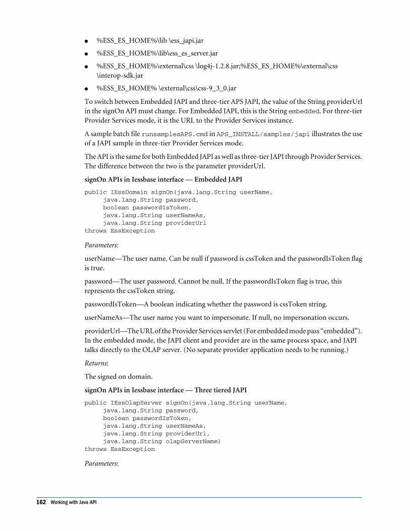
● %ESS_ES_HOME%\lib \ess_japi.jar
● %ESS_ES_HOME%\lib\ess_es_server.jar
● %ESS_ES_HOME%\external\css \log4j-1.2.8.jar;%ESS_ES_HOME%\external\css\interop-sdk.jar
● %ESS_ES_HOME% \external\css\css-9_3_0.jar
To switch between Embedded JAPI and three-tier APS JAPI, the value of the String providerUrlin the signOn API must change. For Embedded JAPI, this is the String embedded. For three-tierProvider Services mode, it is the URL to the Provider Services instance.
A sample batch file runsamplesAPS.cmd in APS_INSTALL/samples/japi illustrates the useof a JAPI sample in three-tier Provider Services mode.
The API is the same for both Embedded JAPI as well as three-tier JAPI through Provider Services.The difference between the two is the parameter providerUrl.
signOn APIs in Iessbase interface — Embedded JAPI
public IEssDomain signOn(java.lang.String userName, java.lang.String password, boolean passwordIsToken, java.lang.String userNameAs, java.lang.String providerUrlthrows EssException
Parameters:
userName—The user name. Can be null if password is cssToken and the passwordIsToken flagis true.
password—The user password. Cannot be null. If the passwordIsToken flag is true, thisrepresents the cssToken string.
passwordIsToken—A boolean indicating whether the password is cssToken string.
userNameAs—The user name you want to impersonate. If null, no impersonation occurs.
providerUrl—The URL of the Provider Services servlet (For embedded mode pass “embedded”).In the embedded mode, the JAPI client and provider are in the same process space, and JAPItalks directly to the OLAP server. (No separate provider application needs to be running.)
Returns:
The signed on domain.
signOn APIs in Iessbase interface — Three tiered JAPI
public IEssOlapServer signOn(java.lang.String userName, java.lang.String password, boolean passwordIsToken, java.lang.String userNameAs, java.lang.String providerUrl, java.lang.String olapServerName)throws EssException
Parameters:
162 Working with Java API
userName—The user name. Can be null if password is cssToken and the passwordIsToken flagis true.
password—The user password. Cannot be null. If the passwordIsToken flag is true, thisrepresents the cssToken string.
passwordIsToken—A boolean indicating whether the password is cssToken string.
userNameAs—The user name you want to impersonate. If null, no impersonation occurs.
providerUrl—The URL of the Provider Services servlet (For embedded mode pass “embedded”).In the embedded mode, the JAPI client and provider are in the same process space, and JAPItalks to Analytic Server directly. (No separate provider application needs to be running.)
olapServerName—The host name where Essbase Server is running.
Returns:
The connected Essbase Server instance.
Note:
Outline editing in Provider Services Release 9.3 works only with Essbase Release 9.3. Outlineediting is performed on the Analytic Server side; therefore, it works only against Essbase Release9.3.
Embedded JAPI 163

164 Working with Java API
13Setting Up the Sample Programs
In This Chapter
Understanding the Sample Programs ... . . . . . . . . . . . . . . . . . . . . . . . . . . . . . . . . . . . . . . . . . . . . . . . . . . . . . . . . . . . . . . . . . . . . . . . . . . . . . . . . . . . . . . . 165
Configuring Provider Servers .. . . . . . . . . . . . . . . . . . . . . . . . . . . . . . . . . . . . . . . . . . . . . . . . . . . . . . . . . . . . . . . . . . . . . . . . . . . . . . . . . . . . . . . . . . . . . . . . . . . 167
Compiling and Running the Sample Programs... . . . . . . . . . . . . . . . . . . . . . . . . . . . . . . . . . . . . . . . . . . . . . . . . . . . . . . . . . . . . . . . . . . . . . . . . . . . . . 168
Compatibility with Earlier Versions of Essbase Server .. . . . . . . . . . . . . . . . . . . . . . . . . . . . . . . . . . . . . . . . . . . . . . . . . . . . . . . . . . . . . . . . . . . . . . . 170
Understanding the Sample ProgramsThe sample programs provided with Provider Services help you test the software and get startedon developing client programs for Provider Services. To run the sample programs, you mustconfigure your environment with the following components:
● A Provider Server
● A supported Essbase Server with users and sample applications
For information about setting up Essbase for the sample programs, see “Configuring ProviderServers” on page 167.
Unless otherwise noted in this document, the sample programs assume that necessary softwarecomponents (Provider Services, Essbase, and the sample programs themselves) are running onthe same computer.
The sample programs demonstrate areas of functionality provided through the Essbase JAPI.The sample programs are in HYPERION_HOME\AnalyticProviderServices\samples. Eachsample program covers an area summarized in the following list:
● BuildDimension.java adds and removes members from the outline in the activedatabase.
● CdfCdm.java shows the use of CDF and CDM.
● CellAttributes.java signs on to Essbase domain, opens a cube view, performs aretrieval, gets the cell attributes, and signs off.
● Connect.java demonstrates a simple connection to an Essbase Server.
● CopyOlapAppAndCube.java copies an Essbase application and cube within the sameEssbase Server; can be extended to perform copying across Essbase Servers.
● CreateCluster.java creates a cluster.
● CreateOlapApp.java creates OLAP applications.
Understanding the Sample Programs 165

● CreateOutline.java demonstrates creating a cube outline: creates dimensions,members, and other outline elements; verifies the outline; and restructures the database.
● CubeDataLoad.java signs onto the Essbase domain, loads data into a cube, and signs off.
● CubeLocks.java signs onto the Essbase domain, gets the list of locks held on a cube, andsigns off.
● DataQuery.java demonstrates basic retrieval of data from an Essbase database.
● DataSource.java demonstrates the retrieval of Essbase Server information and executionof reports.
● Domain.java demonstrates adding, fetching, and removing Essbase Servers from thedomain of Provider Services.
● EditOutline.java signs onto the Essbase domain, connects to an application anddatabase, and performs almost all edit operations on the database outline.
● GetLoginIDRequest.java signs onto the Essbase domain and retrieves the login ID ofthe user signing in; and retrieves the list of executing requests from Essbase Server.
● GetMembers.java signs on to Essbase domain, performs various metadata operations, andsigns off.
● GetOlapUser demonstrates fetching native and external Essbase users.
● GridDataUpdate.java demonstrates retrieving and updating data in a grid format.
● GridLockUnlock.java signs on to an Essbase domain, opens a cube view, performs a lock,retrieval, unlock, and signoff.
● GridWithUnknownMembers.java demonstrates how to detect unknown members in dataquery.
● HisDrillThrough.java signs on to an Essbase domain, opens a cube view, performsOracle's Essbase® Integration Services drill-through, lists reports, executes reports, and signsoff.
● HisDrillThroughOnRange.java signs on to an Essbase domain, opens a cube view,performs Oracle's Essbase® Integration Services drill-through, lists reports, executes reports,and signs off.
● HybridAnalysis.java demonstrates how to use the Hybrid Analysis option for dataquery and metadata operations.
● KillOwnRequest.java cancels a running request issued to an Essbase application serverfrom the same user session.
● LinkedObjects.java signs on to an Essbase domain, opens a cube view, performs aretrieval, performs LRO operations, and signs off.
● LinkedPartition.java signs on to an Essbase domain, opens a cube view, performs aretrieval, looks for a linked partition in a cell, and signs off.
● ListAndKillOlapRequests.java signs on to an Analytic Services domain, connects toan Essbase Server, lists the requests, kills requests, and signs off.
● LoadData.java loads data to a cube.
166 Setting Up the Sample Programs

● MdxQuery.java signs on to an Essbase domain, opens a cube view, performs an MDX queryexecution, retrieves the results, and signs off.
● MetaData.java demonstrates retrieval of metadata information from an Essbase database,including member selection.
● NonUniqueOutline.java tests an existing Sample Basic outline to verify that it allowsunique members only, creates a new outline enabled for duplicate (nonunique) membernames, and uses the duplicate member name JAPIs.
● NonUniqueQueryOutline.java queries a outline enabled for duplicate (nonunique)member names. This sample file is intended to test the duplicate member names outlinecreated using the NonUniqueOutline.java sample.
● PropertyViewer.java gets an application/database object, enumerates its properties, andprints the values.
● QueryHints.java signs on to the Essbase domain, performs query-hints-relatedoperations, and signs off.
● ReadOutline.java signs on to the Essbase domain, reads items in an outline, and signsoff.
● RunReport.java demonstrates running a report from an Essbase database.
● RunXmlReport.java signs on to the Essbase domain, runs a report, and signs off.
● SecurityFilter.java tests the security filters.
● SyncCubeReplicas.java demonstrates the replication of data between two Essbasedatabases.
● TimeDimIntelligence.java demonstrates time intelligence related to the "Date Time"dimension.
● ViewOutlineTree.java demonstrates listing outline members from an Essbase databaseoutline.
The sample programs can use an Analytic Provider Server that uses a supported configuration.For more information about creating client programs that work with Analytic Provider Server,see the online Analytic Provider Server JAPI Reference in the Analytic Provider Server docs\directory.
Configuring Provider ServersThe sample programs require an Essbase Server 7.0 or later server with the Demo Basic sampleapplication loaded. You also must create the user “system” on the Essbase Server.
If you plan to use several Essbase Servers in a cluster with the sample programs, you must performthe following procedure for all Essbase Servers in the cluster.
➤ To configure one or more instances of Essbase Server for use with the sample programs:
1 On the Essbase Server computer, verify that the sample applications Demo Basic and Sample Basic areinstalled and that the databases have been loaded with data.
Configuring Provider Servers 167

For information about copying Essbase applications, see the Analytic Services DatabaseAdministrator's Guide.
2 Optional: If you are using more than one Essbase Server instance in a cluster, repeat step 1.
Compiling and Running the Sample ProgramsAfter you have configured the required servers, you can compile and run the sample programs.
Two script files are provided for compiling the sample programs:
● runsamplesAPS: for use in a three-tier Java API deployment
● runsamplesEmbedded: for use in an embedded Java API deployment
Depending on the deployment option you choose, these scripts must be configured to work withyour computer environment. After the scripts are working in your environment, you can usethem as templates to create, compile, and run scripts for the other sample programs.
Configuring the Script FilesTo configure the runsamplesAPS and runsamplesEmbedded script files to work in yourcomputer environment, you must verify that the path and other environment variables in thescripts are set correctly.
Note:
The procedure in this section applies to both three-tier and Embedded Java API deployments.
➤ To configure the script files to work with your computer environment:
1 In HYPERION_HOME\AnalyticProviderServices\samples, locate the appropriate script.
To deploy the Java API in three-tier mode:
● runsamplesAPS.cmd on Windows
● runsamplesAPS.sh on UNIX
To deploy the Java API in embedded mode:
● runsamplesEmbedded.cmd on Windows
● runsamplesEmbedded.sh on UNIX
2 Using a text editor, open the script file you chose in step 1.
3 Verify that the APS_HOME variable is set to the location of your Provider Services installation; for example:
set APS_HOME=C:\hyperion\AnalyticProviderServices\
4 Verify that the JAVA_HOME variable points to a supported version of the Java Runtime Environment.
If you did not install the Java Runtime Environment with Provider Services, you must updatethis variable with a full path to the Java installation; for example,
168 Setting Up the Sample Programs

set JAVA_HOME="C:\Program Files\Java\jre1.5.0_05"
5 Replace the variable values for USER, PASSWORD, DOMAIN, EES_SERVER, and OLAP_SERVER, as necessary.
These variables are set at the beginning of the script file.
Tip:
To ease running the example programs, set up Provider Services and Oracle's Hyperion®Essbase® – System 9 on your local computer. Then, in Analytic Administration Services Console,create a user “system” with a password of “password” and full access to the Sample Basic, DemoBasic, and Demo2 Basic databases. If you set up your computer system in this configuration,you need not modify the default settings for the sample client programs.
6 Save the script file.
Running the ScriptsAfter you have configured the runsamplesAPS and runsamplesEmbeddedscripts to work withyour environment, you are ready to run the script, which compiles the sample programs andruns one of them.
➤ To run the script:
1 Verify that the Analytic Provider Server and Essbase Server are running.
2 In HYPERION_HOME\AnalyticProviderServices\samples, locate the appropriate script.
To deploy the Java API in three-tier mode:
● runsamplesAPS.cmd on Windows
● runsamplesAPS.sh on UNIX
To deploy the Java API in embedded mode:
● runsamplesEmbedded.cmd on Windows
● runsamplesEmbedded.sh on UNIX
3 To run the script, type the following command at the command prompt.
For example:
>runsamplesAPS http
This example runs the sample program for an Analytic Provider Server three-tier deploymentthat uses HTTP. For other server types, replace HTTP with the server type that you are using.
4 Follow the onscreen prompts to compile and run the sample programs.
Creating Compile and Run ScriptsThe scripts, runsamplesAPS or runsamplesEmbedded, compile all of the sample programsbut run only one of them. To run the other sample programs, you must create your own scripts
Compiling and Running the Sample Programs 169

or modify the runsamplesAPS or runsamplesEmbedded script. You can use either runsamplesscript as a template for new scripts.
➤ To create a version of the runsamples script to run another sample program:
1 In HYPERION_HOME\AnalyticProviderServices\samples, locate the runsamples script(.cmd on Windows systems, .sh on UNIX systems).
2 Open the runsamples script in a text editor.
3 In the script file, find the line that begins echo Step-2, and modify the two lines as shown below:
echo Step-2: Ready to run MetaData example ...pause%JAVA_HOME%\bin\java %VBROKER_PROPS%com.hyperion.essbase.samples.MetaData %USER% %PASSWORD%%DOMAIN% %EES_SERVER% %ORB% %PORT% %OLAP_SERVER%
To use the script to run another sample program, substitute the name of the sample programclass for MetaData, as shown in the preceding sample.
4 Configure this script to work in your computer environment by performing the procedure described in“Configuring the Script Files” on page 168.
5 Save the script file in HYPERION_HOME\AnalyticProviderServices\samples.
Save the file with a .cmd extension on Windows systems or a .sh extension on UNIX systems.
6 Optional: To create a separate script for each sample program that you want to run, repeat this procedure.
Running Compile and Run ScriptsAfter you have created compile and run scripts for the other sample programs and configuredthem to work with your environment, you are ready to run these scripts.
➤ To run the compile and run scripts:
1 Verify that the Analytic Provider Server and Essbase Server are running.
2 In HYPERION_HOME\AnalyticProviderServices\samples, locate the script file (.cmd onWindows systems, .sh on UNIX systems).
3 To run the script, double-click the file or type the script command at the command prompt.
4 Follow the on-screen prompts to compile the sample program and run it.
5 Optional: To run each sample program script that you have created, repeat this procedure.
Compatibility with Earlier Versions of Essbase ServerThe Java APIs applicable to outline editing are supported only starting with Essbase ServerRelease 9.3.0.
170 Setting Up the Sample Programs

AManual Deployment of ProviderServices on Application Servers
In This Appendix
Overview ... . . . . . . . . . . . . . . . . . . . . . . . . . . . . . . . . . . . . . . . . . . . . . . . . . . . . . . . . . . . . . . . . . . . . . . . . . . . . . . . . . . . . . . . . . . . . . . . . . . . . . . . . . . . . . . . . . . . . . . . 171
Deploying on Apache Tomcat.. . . . . . . . . . . . . . . . . . . . . . . . . . . . . . . . . . . . . . . . . . . . . . . . . . . . . . . . . . . . . . . . . . . . . . . . . . . . . . . . . . . . . . . . . . . . . . . . . . 172
Deploying on BEA WebLogic Server 8.1.6... . . . . . . . . . . . . . . . . . . . . . . . . . . . . . . . . . . . . . . . . . . . . . . . . . . . . . . . . . . . . . . . . . . . . . . . . . . . . . . . . . . 173
Deploying on BEA WebLogic Server 9.1 ... . . . . . . . . . . . . . . . . . . . . . . . . . . . . . . . . . . . . . . . . . . . . . . . . . . . . . . . . . . . . . . . . . . . . . . . . . . . . . . . . . . . . 175
Deploying on IBM WebSphere Application Server 6.0.2 and 6.1.0.5 ... . . . . . . . . . . . . . . . . . . . . . . . . . . . . . . . . . . . . . . . . . . . . . . . . . . . 176
Deploying on Oracle 10g – 10.1.2.0.2 or 10.1.3.1.0... . . . . . . . . . . . . . . . . . . . . . . . . . . . . . . . . . . . . . . . . . . . . . . . . . . . . . . . . . . . . . . . . . . . . . 178
OverviewThis appendix describes manually deploying Provider Services on the following applicationservers:
● Apache Tomcat 5.0.28
● BEA WebLogic 8.1.6 or 9.1
● IBM WebSphere 6.0.2 or 6.1.0.5
● Oracle 10g – 10.1.2.0.2 or 10.1.3.1.0
Deployment OptionsYou can deploy automatically or manually:
● Automatic deployment—Use Hyperion Configuration Utility to automatically deploy allfiles to the application server. In most cases, no other deployment tasks are required. Selectthe Automatic deployment option for the application server. See Chapter 3, “ConfiguringProvider Services ” for automatic deployment instructions.
Note:
Oracle 10g cannot be deployed automatically.
● Manual deployment—Follow the instructions in this appendix to deploy Provider Services.The InstalledApps folder contains dummy files for Provider Services manual deploymentand is created when you select Manual Deployment from the Oracle's Hyperion®Configuration Utility™.
Overview 171

Before DeployingBefore you manually deploy Provider Services, you must complete the procedure in “Before YouRun Hyperion Configuration Utility” on page 30 in Chapter 3, “Configuring ProviderServices .” Do this to ensure that the correct Provider Services port number is registered withOracle's Hyperion® Shared Services.
Deploying Provider Services on Application ServersDeploy Provider Services as follows:
● “Deploying on Apache Tomcat” on page 172
● “Deploying on BEA WebLogic Server 8.1.6” on page 173
● “Deploying on BEA WebLogic Server 9.1” on page 175
● “Deploying on IBM WebSphere Application Server 6.0.2 and 6.1.0.5” on page 176
Deploying on Apache TomcatApache Tomcat 5.0.28 is included with Provider Services and is installed and configured bydefault.
However, if you have an existing installation of Apache Tomcat to deploy and configure for usewith Provider Services, perform the following steps.
➤ To deploy the Provider Services files to Apache Tomcat Server:
1 If Apache Tomcat is running, stop the application server.
2 Copy the aps.war file from $HYPERION_HOME\analyticproviderservices\AppServer\InstallableApps\Common to your \tomcat\5.0.28\webapps directory.
3 Copy the essbase.properties file to the /bin folder of Tomcat.
4 To configure the port, edit <tomcat_home>/conf/server.xml as shown in bold:
<!-– Define a non-SSL HTTP/1.1 Connector on port 8080 ––> <Connector port="13080" maxHttpHeaderSize="8192" maxThreads="150" minSpareThreads="25" maxSpareThreads="75" enableLookups="false" redirectPort="8443" acceptCount="100" connectionTimeout="20000" disableUploadTimeout="true" />
5 Start Apache Tomcat to complete the deployment process.
6 Start Provider Services and verify successful deployment by entering the URL for Provider Services into abrowser.
The URL syntax is http://<hostname>:<port number>/aps/APS .
For example, if the HTTP port on which Provider Services is deployed is 13080, enter thefollowing URL into your browser:
http://localhost:13080/aps/APS
172 Manual Deployment of Provider Services on Application Servers

Deploying on BEA WebLogic Server 8.1.6To prevent the Web application being deployed from inheriting unwanted runtime settings, youmust create and use a new server. Deploying more than one Web application to the same servermay yield unsuccessful results.
Deploying BEA WebLogic Server application server manually to work with Provider Services,involves the following procedures:
● Creating a custom profile (recommended, but optional)
● Defining ESS_ES_HOME in your environment
● Deploying BEA WebLogic Server
Note:
If you plan to deploy in a named domain (not the default domain), see WebLogic for deploymentinstructions.
➤ To create a new WebLogic domain:
1 Launch the BEA WebLogic Configuration Wizard.
Under $BEA_HOME/weblogic81/common/bin, use config.sh or config.cmd to run thedomain configuration wizard.
2 Select Create a new WebLogic configuration.
3 Select WebLogic Configuration Template > BEA > Basic WebLogic Server Domain.
4 Optional: To change settings such as listening port and server name, select CUSTOM and change settingsin your domain source.
If you do not want to change settings, click EXPRESS.
5 Enter the admin user name and password.
6 Select the appropriate JDK.
7 In Configuration Name, enter a domain name, and then Browse and navigate to the correct location forthis domain.
8 Click Create.
➤ To define ESS_ES_HOME in your environment, add the following Java parameter to the startupfile, StartWLS.cmd:
-DESS_ES_HOME="c:\hyperion\analyticproviderservices"
For example:
:runAdmin@echo on"%JAVA_HOME%\bin\java" -DESS_ES_HOME="c:\hyperion\analyticproviderservices" %JAVA_VM% %MEM_ARGS% %JAVA_OPTIONS% -Dweblogic.Name=%SERVER_NAME% -Dweblogic.management.username=%WLS_USER% -Dweblogic.management.password=%
Deploying on BEA WebLogic Server 8.1.6 173
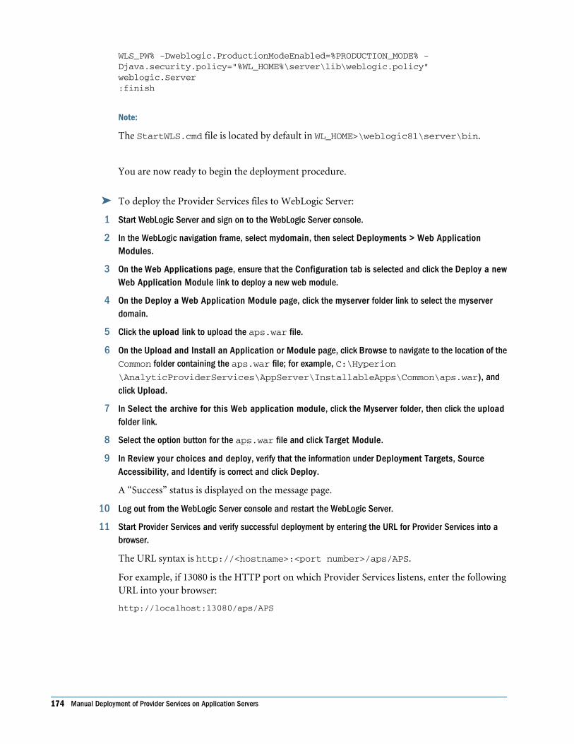
WLS_PW% -Dweblogic.ProductionModeEnabled=%PRODUCTION_MODE% -Djava.security.policy="%WL_HOME%\server\lib\weblogic.policy"weblogic.Server:finish
Note:
The StartWLS.cmd file is located by default in WL_HOME>\weblogic81\server\bin.
You are now ready to begin the deployment procedure.
➤ To deploy the Provider Services files to WebLogic Server:
1 Start WebLogic Server and sign on to the WebLogic Server console.
2 In the WebLogic navigation frame, select mydomain, then select Deployments > Web ApplicationModules.
3 On the Web Applications page, ensure that the Configuration tab is selected and click the Deploy a newWeb Application Module link to deploy a new web module.
4 On the Deploy a Web Application Module page, click the myserver folder link to select the myserverdomain.
5 Click the upload link to upload the aps.war file.
6 On the Upload and Install an Application or Module page, click Browse to navigate to the location of theCommon folder containing the aps.war file; for example, C:\Hyperion\AnalyticProviderServices\AppServer\InstallableApps\Common\aps.war), andclick Upload.
7 In Select the archive for this Web application module, click the Myserver folder, then click the uploadfolder link.
8 Select the option button for the aps.war file and click Target Module.
9 In Review your choices and deploy, verify that the information under Deployment Targets, SourceAccessibility, and Identify is correct and click Deploy.
A “Success” status is displayed on the message page.
10 Log out from the WebLogic Server console and restart the WebLogic Server.
11 Start Provider Services and verify successful deployment by entering the URL for Provider Services into abrowser.
The URL syntax is http://<hostname>:<port number>/aps/APS.
For example, if 13080 is the HTTP port on which Provider Services listens, enter the followingURL into your browser:
http://localhost:13080/aps/APS
174 Manual Deployment of Provider Services on Application Servers

Deploying on BEA WebLogic Server 9.1To prevent the Web application being deployed from inheriting unwanted runtime settings, youmust create and use a new server. Deploying more than one Web application to the same servermay yield unsuccessful results.
Deploying BEA WebLogic Server application server manually to work with Provider Services,involves the following procedures:
● Creating a custom profile (recommended, but optional)
● Defining ESS_ES_HOME in your environment
● Deploying BEA WebLogic Server
➤ To create a WebLogic domain (You can use an existing domain; perform this procedure onlyto create a new domain.)
1 Launch the BEA WebLogic Configuration Wizard.
Under $BEA_HOME/weblogic91/common/bin, use config.sh or config.cmd to run thedomain configuration wizard.
2 Select Create a new WebLogic domain.
3 Select Generate a domain configured automatically to support the following BEA WebLogicproducts.
WebLogic Server is selected by default.
4 Enter the admin user name and password.
5 Select the appropriate JDK.
6 Optional: To change settings such as listening port and server name, select YES and change settings in yourdomain source.
If you do not want to change settings, click No.
7 Enter a domain name and location.
8 Click Create.
➤ To deploy Provider Services files to WebLogic 9.1 Server:
1 Start WebLogic Server and sign on to the WebLogic Server console.
2 In the left panel within the Change Center, click Lock & Edit.
3 In the WebLogic navigation frame, select Deployments.
4 Click the Install button on the right panel of the Control tab.
5 Click the Upload your file(s) link to upload the aps.war file.
6 On the Install Application Assistant page, click the Browse button of the Deployment Archive text fieldto navigate to the location of the Common folder containing the aps.war file; for example, C:\Hyperion\AnalyticProviderServices\AppServer\InstallableApps\Common
\aps.war, and click Next.
Deploying on BEA WebLogic Server 9.1 175

7 Select the aps.war archive on the displayed page and click Next.
8 On the Choose targeting style page select the Install this deployment as an application option and clickNext.
9 On the Select deployment targets page, select the servers on which to deploy Provider Services.
10 Click Finish on the Optional Settings page.
11 Click the Environment > Server node on the left panel.
12 On the Summary of Servers page, select the Configuration >Server Start tab.
13 In Arguments, enter:
-DESS_ES_HOME=<APS_HOME>Ex: -DESS_ES_HOME=C:\Hyperion\AnalyticProviderServices
14 Click Activate Changes at the top left of the Control Center.
15 On the Summary of Deployments page, select aps.war and click Start.
16 Click Yes on the Start Deployments page.
The state column for aps.war should be displayed as ACTIVE.
17 If you are in Production mode, start the application.
18 Verify successful deployment of Provider Services by entering the URL for Provider Services into a browser.
The URL syntax is
http://<hostname>:<port number>/aps/APS.
For example, if 13080 is the HTTP port on which Provider Services listens, enter the followingURL into your browser:
http://localhost:13080/aps/APS
Deploying on IBM WebSphere Application Server 6.0.2 and6.1.0.5
To prevent the Web application being deployed from inheriting unwanted runtime settings, youmust create and use a new application server. Deploying more than one Web application to thesame application server may yield unsuccessful results.
Deploying WebSphere Application Server application server manually to work with ProviderServices, involves the following procedures:
● Creating a custom profile (optional, but recommended so that the default WebSphere serveris available for others to use)
● Deploying IBM WebSphere Application Server (includes defining ESS_ES_HOME in yourenvironment)
➤ To create a new WebSphere profile:
1 Launch the Profile Creation Wizard.
176 Manual Deployment of Provider Services on Application Servers

Under $WAS_HOME/AppServer/bin/ProfileCreator, use pctWindows.exe orpct<UNIX_OS>bin to run the Profile Creation Wizard.
2 Click Next in the Welcome page.
3 Enter the Profile name, then click Next.
4 Enter the Profile Directory, then click Next.
5 Enter the Node and Host Name, then click Next.
6 Enter the Port Value, then click Next.
7 Ignore the Run as Windows Service, then click Next.
8 Review the Creation Summary, then click Next.
9 Select First Steps Verification, then click Next.
Running “First Steps Verification” will verify that the server under your new profile can start upcorrectly. If the profile can start correctly, the server is started.
Note:
You can also start the server by running $WAS_HOME/AppServer/profiles/<profile_name>/bin/startServer.sh server1.
➤ To deploy the Provider Services files to WebSphere Application Server:
1 Bring up the WebSphere Administrative Console by typing the appropriate URL in a browser.
For example:
http://<hostname>:<port number>/ibm/console
2 In the Login window, type your user ID in the text box and click OK.
3 In the left frame of the Administrative Console, select Applications > Install New Application.
4 On the Preparing for the application installation page, click Browse and navigate to the $APS_HOME\AppServer\InstallableApps\Common\aps.war file.
5 In the Context Root text box, type /aps and click Next.
6 In the Generate Default Bindings box, accept the default values by clicking Next.
Note:
If you get the “Application Security Warnings” page, you may ignore and click Continue.
7 In Step 1 Provide options to perform the installation, click Next to accept the default values shown inAppDeployment Options.
8 In Step 2 Map modules to application servers, check APSWebModule to indicate that aps.war is themodule to map to the WebSphere server, and then click Next.
9 In Step 3 Map virtual hosts for web modules, click APSWebModule to select it as the default host, thenclick Next.
10 In Step 4 Summary, click Finish to initiate the installation.
Deploying on IBM WebSphere Application Server 6.0.2 and 6.1.0.5 177

When the installation is completed, a message advises you that the aps_war application issuccessfully installed.
11 Click Save to Master Configuration, then click Save to save the Provider Services manual deploymentconfiguration.
12 In the left frame of the Administrative Console, select Servers > Application Servers.
13 When the Application Servers page is displayed, click on the server1 instance.
14 In the server1 configuration page, in the Server Infrastructure section, navigate to Java and ProcessManagement > Process Definition > Java Virtual Machine.
15 In the Java Virtual Machine page, Generic JVM Arguments, enter:
-DESS_ES_HOME=<APS_HOME>
<APS_HOME> is the Provider Services install root path.
For example, if you have installed Provider Services on Windows and C:\Hyperion\AnalyticProviderServices is the installation root directory, then enter:
-DESS_ES_HOME=C:\Hyperion\AnalyticProviderServices
16 Click Apply, followed by OK and then select Save to Master Configuration.
17 Add Host Alias for port 13080 to the default_host virtual host.
18 Add port 13080 for the web container transport chain to the APS application server.
19 Start or restart the Provider Services server.
20 Verify successful deployment of Provider Services by entering the URL for Provider Services into a browser.
The URL syntax is
http://<hostname>:<port number>/aps/APS.
For example, if 13080 is the HTTP port on which Provider Services listens, enter the followingURL into your browser:
http://localhost:13080/aps/APS
Deploying on Oracle 10g – 10.1.2.0.2 or 10.1.3.1.0To prevent the Web application being deployed from inheriting unwanted runtime settings, youmust create and use a new OC4J instance. Deploying more than one Web application to thesame OC4J instance may yield unsuccessful results.
Provider Services does not require modifications to Oracle HTTP Server listen port(s). However,if you wish to modify these ports, it is recommended that you do so before continuing. Refer tothe appropriate Oracle® Application Server guide for details on changing port numbers.
Creating an OC4J InstanceFollow the instructions in the Oracle® Containers for J2EE Configuration and AdministrationGuide to create a new OC4J instance called APS.
178 Manual Deployment of Provider Services on Application Servers

Note:
OC4J group administrative settings such as environment variables are shared by all groupmembers. The OC4J instance you create for the Web application being deployed should beassigned to a group created specifically for that application. (When an application is deployedto more than one OC4J instance, those instances can be assigned to the same group.) Forexample, when deploying Shared Services and Workspace, the OC4J instance created for SharedServices should be assigned to a different group than the instance created for Workspace. Referto the Oracle® Process Manager and Notification Server Administrator's Guide for moreinformation about groups.
Setting Heap SizeWhen Provider Services is deployed to Oracle 10g release 3 on any operating system other thanAIX, the Java argument -XX:MaxPermSize must be added. Without this parameter, ProviderServices will run out of memory in the permanent generation heap(java.lang.OutOfMemoryError: PermGen space) and terminate abruptly.
➤ To set heap size:
1 On the Enterprise Manager Application Server control page, under All Application Servers, click the serverinstance on which Provider Services was deployed.
2 Click the Administration tab.
3 Under Command Line Options, set heap size:
-XX:PermSize=64m
-XX:MaxPermSize=128m
Deploying on Oracle 10g
➤ To deploy the Provider Services files to Oracle 10g:
1 Select the new OC4J instance that you created in the previous procedure.
2 Select Applications > Deploy WAR file.
3 Browse to the war file you want to deploy.
4 Specify application name; for example, aps.
Note:
The application name cannot have contain quotation marks (” “).
5 Specify a URL; for example, /aps.
Note:
The URL is a context root.
Deploying on Oracle 10g – 10.1.2.0.2 or 10.1.3.1.0 179

6 Click Deploy > OK.
7 Add ESS_ES_HOME to your environment:
a. Select the Administration tab, and then select Server Properties.
b. Under Command Line Options, add the following to the Java Options:
-DESS_ES_HOME=C:\Hyperion\<APS_HOME>
<APS_HOME> is the location of your Provider Services installation.
c. Click Apply, then OK.
8 Select OC4J:<instance_name> > Home > Start > OK.
9 Verify successful deployment of Provider Services by entering the URL for Oracle's Hyperion® Provider Servicesinto a browser.
The URL syntax is
http://<server>:<portnumber>/aps/APS
180 Manual Deployment of Provider Services on Application Servers

Index
Hyperion Configuration Utilityadding to Administration Services Console, 56connecting to, 45, 61disconnecting from, 46node in Administration Services Console, 70removing, 56Shared Services compatibility matrix, 54shutting down, 46starting, 45upgrades, configuring, 31
Aadding
Provider Services, 56Analytic Cluster, 58cluster component, 59
AIXinstalling on, 21setting environment before installation, 19
Analytic Administration Services Console, using toadminister Hyperion Provider Services, 70
Analytic Clusteradding, 58removing, 59
Apache Tomcat Application Serverdeploying manually, 172
application serverdeployment, 35deployment options, 171
application servers, deploying manually, 172APS.instance file, editing, 30authenticating EssbaseServer, 56automatic deployment of Smart View client, 64
Bbackground process, running Provider Services as,
45
BEA WebLogic Application Serverdeploying manually, 173
browser support, documentation, 25
CCD. See DVDcharacters, restricted, 30closing Provider Services, 46cluster component
adding, 59disabling, 61enabling, 60removing, 60
clusteringAnalytic Servers, 67Hyperion Provider Services, 75
Tomcat, 78WebLogic, 81
Oracle 10g Application Server, 102clusters, 67
connecting to, 58defining, 68
code pages, setting the ESSLANG environmentvariable, 28
configurationdeployment, 35deployment, profiles and domains, 36prerequisites, 30product upgrades, 31Shared Services registration, 33restricted characters, 30task list, 29task sequence, 30troubleshooting, 30
configuration options in essbase.properties file, 65Hyperion Configuration UtilityConfiguration Utility
before running, 30
A B C D E F H I L M O P R S T U V W X
Index 181

deployment, 35description, 29prerequisites, 30reconfiguration, 37Shared Services registration, 33task sequence, 30
connecting to, 61Provider Services, 45, 61Analytic Clusters, 58stand-alone Analytic Servers, 57
connection pools, 67console mode, launching UNIX installers, 20
Ddebug messages, 62defining clusters, 67, 68defining pools, 67deployment, 35directories
AnalyticProviderServices, 24spaces in install directory, 21
disabling cluster component, 61Discover method, 118documentation
browser support, 25installed, 24
downloading installers, 20DVD, launching installers from, 20
Eediting
authenticating EssbaseServer, 56editing log message levels, 62enabling cluster component, 60environment, setting on UNIX, 19error logs, 30error messages, 62essbase.properties file
configuring, 65olap.server.netConnectRetry, 65olap.server.netDelay, 66olap.server.netRetryCount, 66olap.server.netSocketTimeOut, 67options configurable in, 65
ESSLANG environment variable, described, 28Execute method, 121
exiting Provider Services, 46
Ffailover support, 58, 72fatal messages, 62fault tolerance, 72flattened rowsets, 152folders installed
HYPERION_HOME directory, 25foreign language support, 28
Hheap size
setting for Oracle 10g deployment, 179horizontal clustering, 75HP-UX
installing on, 21setting environment before installation, 19
Hyperion Download Center, launching the installerfrom, 20
Hyperion Home, 25Hyperion Provider Services
uninstalling, 47Hyperion Provider Services clustering, 75HYPERION_HOME environment variable, 25
detecting existing on UNIX, 19
Iinformation messages, 62installation instructions, 21installed documentation, 24installers, launching, 20installers, launching on UNIX, 20
Llaunching installers, 20launching installers on UNIX, 20Linux
installing on, 21setting environment before installation, 19
load balancing, 58LOCALE directory, 28log message levels, 62
A B C D E F H I L M O P R S T U V W X
182 Index

Mmaximum rows and columns, specifying, 63MBCS support, 28migrating
Smart View client software, 50users from previous releases, 50
monitoring sessions, 62
OOC4J, 178olap.server.netConnectRetry in essbase.properties,
65olap.server.netDelay in essbase.properties, 66olap.server.netRetryCount in essbase.properties, 66olap.server.netSocketTimeOut in essbase.properties,
67Oracle 10g
deploying manually, 178Oracle 10g Application Server, 102overinstallation, 22
PProgram Files directory, installing to, 21
Rreconfiguration, 37registration, Shared ServicesShared Services, 33removing
Provider Services, 56Analytic Cluster, 59cluster component, 60stand-alone Analytic Server, 58
repairing Smart View, 47restricted characters, 30
Sserver clusters, 68session time out, specifying, 63Shared Services, 15
about, 53migration prerequisites, 53starting, 39stopping, 42
shortcuts on Start menu, 24SiteMinder, 37
Smart View clientrepairing, 47uninstalling, 47upgrading from previous releases, 50
Solarisinstalling on, 21setting environment before installation, 19
spaces, in install directory name, 21SSL configuration, 105stand-alone Analytic Server
connecting to, 57removing, 58
startingShared Services, 39
startup commandsfor Shared Services server, 39
startup, verifying for Shared Services, 41stopping, 46
Shared Services, 42
TTomcat support, 23tracing XML traffic, 62troubleshooting, 30
Uuninstalling
Hyperion Provider Services, 47Smart View client, 47
UNIXinstalling on, 21launching installers, 20setting environment before installation, 19
upgradesconfiguring, 31
upgrading Smart View client, 50User Management Console
launching, 41users, upgrading from previous releases, 50
Vverifying startup of Shared Services, 41vertical clustering, 75
A B C D E F H I L M O P R S T U V W X
Index 183

Wwarning message, 62WebLogic
single profiling, 36WebSphere
single domain, 36Windows
installing on, 21Start menu, 24
Windows services, 35starting, 39
XXML for Analysis, 117XML tracing, 62XMLA methods, 117XMLA reference, 117XMLA rowsets, 123XWindows, launching installers in, 20
A B C D E F H I L M O P R S T U V W X
184 Index