installation and assembly guide - fabick cat and assembly guide 2 need to know ..... 5°c / 9°f 211...
TRANSCRIPT

fast easy reliable
Installation and Assembly Guide
www.airnet-system.com

2
Need to Know ...............................................................................................................................................................................3
Pre-Installation ........................................................................................................................................................................4-5
Installation .............................................................................................................................................................................. 6-23 • Ø 20 - 50 mm / 3/4” - 2” (PF Series) ................................................................................................................................. 6
• Ø 63 - 80 mm / 21/2” - 31/2” (Classic) .................................................................................................................................. 9
• Ø 100 mm / 4”.................................................................................................................................................................. 12
• Ø 158 mm / 6”.................................................................................................................................................................. 15
• Quickdrops (Ø 20 - 80 mm / 3/4” - 3”) ............................................................................................................................. 17
• Replacing Classic Series with PF Series ......................................................................................................................... 18
• Pipeclips Installation........................................................................................................................................................ 20
• Valve Support ................................................................................................................................................................... 21
• Conductivity Strip............................................................................................................................................................. 22
• Adapter Union .................................................................................................................................................................. 23
Safety and Security ........................................................................................................................................................ 24-25
TABLE OF CONTENTS

3
NEED TO KNOW
Diameters20-50mm 3/4” - 2” (PF Series)
Diameters63 - 80mm 2 1/2”- 3” (Classic)
Diameter 100mm / 4” Diameter 158mm / 6”

4
PRE-INSTALLATION
What is the furthest point pressure drop?
The furthest point pressure drop is the
difference in pressure between the point
of generation and the furthest point in your
installation.
A high pressure drop means the regulating
pressure on the compressor needs to be set
higher to compensate for the pressure drop.
As a 1 bar (15 psi) additional operating
pressure results in about 7% higher energy
consumption, pressure drops drastically
increase the electrical bill.
The pressure drop is influenced by various factors which we can classify from highest to lowest impact:
The pipes’ inner diameterIncreasing the pipes’ inner diameter reduces the pressure drop but increases the investment.
Free air deliveryThe air demand of all downstream equipment connected to the portion of network.
The friction factorRelated to the pipe’s material. Aluminium has a very low friction factor as opposed to galvanized pipes.
The structureIt is recommended to build a ring in order to reduce your pressure drop.
The length of the networkThe longer the network, the higher the pressure drop.
Working pressureWhen the working pressure is lower, the pressure drop increases.
Equivalent length of fittingEvery fitting can be represented by an equivalent length of pipe that would cause the pressure drop.

5
Long straight pipes can expand or contract due to temperature variations. To compensate for this effect, expansion loops are required. The number of expansion loops depends on the total length of the straight line and the maximum temperature variation. An expansion loop is a U-shaped construction that compensates the variation in length. They look like this:
The below table clarifies the maximum possible straight distance vs. the temperature variation. When the length of the straight line exceeds the maximum, expansion loops are required to compensate for the variation in length.
Dilatation and Expansion loops
PRE- INSTALLATION
DT Ø20 mm / ¾” Ø25 mm / 1” Ø40 mm / 1½” Ø50 mm / 2” Ø63 mm / 2½” Ø80 mm / 3” Ø100 mm / 4”
5°C / 9°F 211 m / 692 ft 168 m / 551 ft 187 m / 614 ft 150 m / 492 ft 119 m / 390 ft 94 m / 308 ft 75 m / 247 ft
10°C / 18°F 159 m / 522 ft 127 m / 417 ft 141 m / 463 ft 113 m / 371 ft 90 m / 295 ft 71 m / 233 ft 57 m / 186 ft
20°C / 36°F 107 m / 351 ft 85 m / 279 ft 95 m / 312 ft 76 m / 249 ft 60 m / 197 ft 47 m / 154 ft 38 m / 123 ft
30°C / 54°F 80 m / 262 ft 64 m / 210 ft 71 m / 233 ft 57 m / 187 ft 45 m / 148 ft 36 m / 118 ft 29 m / 94 ft
40°C / 72°F 64 m / 210 ft 52 m / 171 ft 57 m / 187 ft 45 m / 148 ft 36 m / 118 ft 29 m / 95 ft 23 m / 76 ft

6
INSTALLATION
Diameters 20-50mm / 3/4”- 2”(PF Series)
ø S
40mm / 1 1/2” 63mm / 2 1/2”
50mm / 2” 78mm / 2 5/6”
S Slength (l)
Length L = l + (2xS)
2810 0640 80110V
2810 0540 80230V
≤10°
2810 0141 00Ø 20-50 mm 2810 0040 00Ø 20-50 mm
1
2 OR

7
INSTALLATION
2810 0148 00
Diameters 20-50mm / 3/4”- 2”(PF Series)
2811 4028 00Ø 40 mm
2811 5028 00Ø 50 mm
2810 0141 00Ø 20-50 mm
3
2810 0641 002810 0641 00
OR 4
5
CHECK
76

8
INSTALLATION
Diameters 20-50mm / 3/4”- 2”(PF Series) - Installing with limited force available
2811 4028 00Ø 40 mm
2811 5028 00Ø 50 mm
360°CW
360°CCW
CHECK
4
2
3
1

9
Diameters 63 - 80mm2 1/2”- 3” (Classic)
INSTALLATION
Lenght S Sl
L = l + (2xS)
ø S
20mm / 3/4” 49mm / 2”
25mm / 1” 62mm / 2 1/2”
63mm / 2 1/2” 90mm / 3 1/12”
80mm / 3” 115mm / 4 1/2”
1
≤10°
2810 0040 00Ø 20-50 mm
2810 0140 00Ø 63-100 mm
2
2810 0640 80110V
2810 0540 80230V
OR

10
INSTALLATION
Diameters 63 - 80mm2 1/2”- 3” (Classic)
2810 0148 00
2810 0741 00
OR
2810 0029 00
4
5
2810 0141 00Ø 20-50 mm
3
2810 0641 002810 0641 00
OR

11
INSTALLATION
Diameters 63 - 80mm2 1/2”- 3” (Classic)
2810 6028 00Ø 63 mm
2810 7028 00Ø 80 mm
2811 4028 00
6
7
180°
ø 20 & 25mm8
45°
ø 63 & 80mm OR

12
Diameter 100mm / 4”
S Slength (l)
Length L = l + (2xS)
1
≤3°
2810 0140 00Ø 60-100 mm
2
2810 0640 80110V
2810 0540 80230V
OR
ø S
100mm / 4” 65,5mm / 2 1/2”

13
Diameter 100mm / 4”
2810 0641 00ALL
3
2810 0148 00
2810 0641 002810 0741 00
OR
2810 0129 00
4
6
5

14
Diameter 100mm / 4”
INSTALLATION
4x
0-5 Nm0-3.7 lbs/ft
0462 7094 21wrench
0462 1011 05head
1
2
3
4
7
40Nm29,5 lbs/ft
5
6
7
8
0462 7094 21wrench
0462 1011 05head
8
9 10

15
Diameter 158mm / 6”
INSTALLATION
S Slength (l)
Length L = l + (2xS)
1
2810 0641 00ALL
3≤3°2
2810 0640 80110V
2810 0540 80230V
ø S
158mm / 6” 55mm / 2 1/8”
OR
OR
2810 0240 00
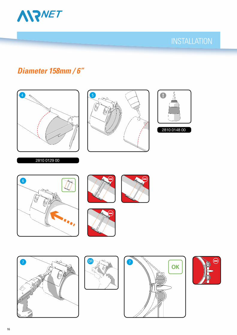
16
INSTALLATION
Diameter 158mm / 6”
2810 0148 00
OR
2810 0129 00
4
7 7
6
5
OK

17
3
INSTALLATION
Quick Drop AssemblyDiameters 20 - 80mm / 3/4” - 3”
180°
2810 0641 002810 0143 00Ø 20 mm drill bit
2810 0043 00Ø 25 mm drill bit
1 2
5
7 8
64

18
D
INSTALLATION
Replace Classic Series with new PF-Series
2810 0640 80110V
2810 0540 80230V
≤10°
2810 0141 00Ø 20-50 mm 2810 0040 00Ø 20-50 mm
3
1 2
OR
D B1 B2 Difference
ø 40mm 38mm 23mm 28mm 23mm 9mm 35mm
ø 50mm 37,5mm 32mm 35mm 32mm 0mm 34mm
ø 1,5“ 1,5” 0,875” 1,125” 0,875” 0,375” 1,375”
ø 2” 1,5” 1,25” 1,375” 1,25” 0” 1,375”

19
INSTALLATION
Replace Classic Series with new PF-Series
2810 0641 002810 0641 00
OR
2811 4028 00Ø 40 mm
2811 5028 00Ø 50 mm
5
2810 0148 00
6
CHECK
87
2810 0141 00Ø 20-50 mm
4
2810 0641 002810 0741 00
OR

20
INSTALLATION
Pipe Clips Installation (Ø20 - Ø100)

21
INSTALLATION
Valve Support
Ed Posi-tion Modified from Date Intr./Appd.
1 2 3 5 6 7 8 9
G
4 10
A
B
C
D
E
F
Parent 3D model Ed . Version 3DCONF
IDEN
TIAL:
This
docu
ment
isou
rprop
erety
ands
halln
otwi
thout
ourp
ermiss
ionbe
altere
d,co
pied,
used
forma
nufac
turing
orco
mmun
icated
toan
yothe
rper
sono
rcom
pany
.
01 Production release 2811506400 01.00AIR154302013-11-04Fini wt.
Approved.
Treatment
Material
Name
Drawn by
Des checked.
Version Drwg
Scale
Blank wtProd checked.
Family
Blank nr.
Kg Designation Sheet
INV
Replaces
Compare
DateKg
Drawing owner
/
Confidentiality Class
STATUS
Tolerances, if not indicated, according to:
ATLAS COPCO STANDARD CLASS
A3
0011 9034 94
1 1
2013-10-18 2811506400
1:1
0 0,232
2
FIXATION WALLBRACKET
.P/.N/.Y
01.00
Approved
AIR15430 CTS
VALVE D50 acc. to 1102 K
Allm
ater
ials
supp
lied
are
inco
mpl
ianc
ew
ithth
ere
quire
men
tsof
the
List
ofPr
ohib
ited
Subs
tanc
es
370
R4
R1 (3x)
78,6 - 00,2+
70
R1 (4x)
11,7 - 00,1+
5,4
- 00,1
+
R4R1 (3x)3
76,5
47
92,4
R4R9
R9
9 (2x)
18138
1836
partnumber here
General tolerances
1350K - f
NOTES:-Bending radius 4mm-Bending angle 90°-All burrs and sharp edges removed
(23,
7)
7
3,5
18

22
INSTALLATION
Conductivity Strip(PF Series only)
Conductivity Strip(Optional - in case of small diameters)
MARK
R
MARK
L1
CHECK
R
CHECK
L4
CHECK
6
2
5
3
number of strips

23
INSTALLATION
Adapter Union
64 5
CHECK
7 8
1 2 3
45°

24
SAFETY & SECURITY
• AIRnet has been designed to convey compressed air,
inert gasses and vacuum.
• The installer must employ safe working practices and observe all related local work safety requirements and regulations.
• Installation, operation, maintenance and repair work must be performed by authorised, trained, specialised personnel.
• Before any installation, maintenance, repair work, adjustment or any other non-routine checks, relieve the system of pressure and effectively isolate the system from all sources of pressure.
• Never use the components below or in excess of its limit ratings.
• 13bar(g) safety valve should be present in installations for applications >13bar (g).
• AIRnet pipes and fittings are not suitable for embedded or buried installations.
• Do not use the AIRnet system as support for electrical equipment or earth conductor
• Use the correct tools
• Use only genuine parts
• The fittings are sensitive to direct UV radiation, in case of direct exposure, shield the fittings. The AIRnet pipes offer excellent resistance to UV radiation.
• AIRnet piping must be appropriately protected against violent impacts.
• Any plugs or caps must be removed before installing the pipes.
• Never use solvents or chemicals which can damage materials of the AIRnet.
• Check the surface of the AIRnet pipe (no relevant scratches, abrasions, dents,…) before installing
• Never connect AIRnet pipes directly to a source of vibrations, use hoses instead.
• Before using a system, an installer must ensure that all necessary test controls and applicable rules for compressed air installations are complied.
• At initial start up, apply a test pressure of 1.5 bar to the system to identify leakage or imperfect joints. After performing the inspection, increase the pressure gradually and constantly (max. 1 bar every 30 seconds).
• AIRnet is suitable for use with compressed air (lubricated, oil free, dry and wet), vacuum (20-80mm and 158mm, 0.13bar) and nitrogen gas.*
*Always consult local regulations for above use
Operating Conditions & Safety Instructions

25
-20°C +50°C -4°F +122°F
DO NOT STRIKE
COMPATIBLE WITHLUBRICANTS
REUSEABLE
DO NOT BEND RESPECT GEOMETRY OF FITTINGS
4 bar 13 bar 60psi 188 psi
-20°C +70°C -4°F +158°F
Rh 100% -70°C-94°F
SAFETY & SECURITY

www.airnet-system.com
97/23/ECASME B31.1EN755QualicoatTest in accordance with EN 10204TUV Certification DR97/23/EG art. 3.3
2946
700
2 65
- ©
Jan
uary
201
4 - S
ubje
ct to
alte
ratio
n w
ithou
t prio
r not
ice.
Your Dealer
fast Thanks to a smart design and low weight materials, AIRnet can be installed 70% faster than conventional systems.
easy AIRnet pipes and fittings are assembled in just a few steps by a single installer, without the need for heavy machinery.
reliable The durable, corrosion-free AIRnet pipes and fittings come with a 10-year warranty. Low friction and seamless connections minimize pressure drop.