installation and operating instructions bulletin 440p · pdf fileinstallation and operating...
TRANSCRIPT
Installation and Operating InstructionsBulletin 440P DIN 50041 IEC/Large Metal Body Safety Limit Switch
IMPORTANT: SAVE THESE INSTRUCTIONS FOR FUTURE USE.
Specifications
See the our website for additional information and product selection.
Electrical life is dependent on load, therefore, operations are not applicable and withdrawn.
ISO 14119 defines types of interlocking devices and coding:
The products shown on this document conform with the Essential Health and Safety Requirements (EHSRs) of the European Machinery Directive. They are third party certified to EN 60947-5-1 and EN ISO 14119.
AC/DC Designation A600; Q600
AC/DC Utilization Category
Alternating current: AC15 (50/60 Hz)Ue (V): 120 240 500 600le (A): 6 3 1.4 1.2Direct current: DC13Ue (V): 125 250 500 600le (A): 0.55 0.27 0.13 0.1
Max. Fusing Rate 10 A fast actingImpulse Voltage (Uimp) 2500V
Enclosure Protection IP66Pollution Degree 3
Storage/OperatingTemperature
-25…+65 °C (-13…+149 °F)
Direct Opening Action Normally closed only (safety circuit)Conductor Sizes Use copper conductors only
Stranded [mm2 (in.2)]0.75…2.5 (0.02…0.09)(18…14 AWG)
Solid [mm2 (in.2)]0.75…2.5 (0.02…0.09)(18…16 AWG)
Product Intended Use
440P Cam actuated
Product Type Coding
440P 1 Uncoded
ATTENTION Improper selection or installation of the devices affect the integ-rity of the safety systems. Personnel injury or death, property damage or economic loss can result.
Comply with ISO 14119 including selection, accessibility to the installation, arrange-ment and fastening, possible substitute actuation, access to the escape release, moti-vation to defeat, and actuation mode. Management controls, working procedures, training, and additional protective mea-sures should be used to minimize the motivation to defeat and to manage the use and availability of spare actuators.Comply with ISO 13857 and ISO 13855 for guard openings and minimum (safe) dis-tances.Comply with IEC 62061 or ISO 13849-1 and ISO 13849-2 for functional safety.
Declaration of Conformity and certification: www.rockwellautomation.com/certification/ce.page
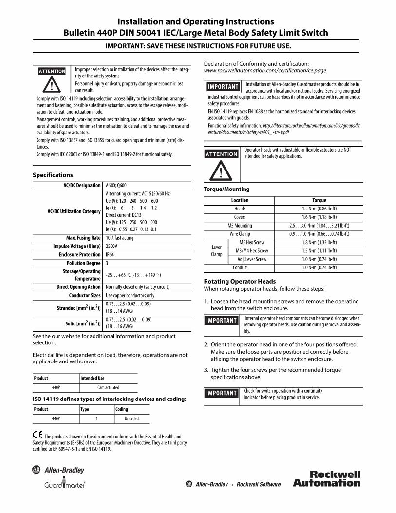
Torque/Mounting
Rotating Operator HeadsWhen rotating operator heads, follow these steps:
1. Loosen the head mounting screws and remove the operating head from the switch enclosure.
2. Orient the operator head in one of the four positions offered. Make sure the loose parts are positioned correctly before affixing the operator head to the switch enclosure.
3. Tighten the four screws per the recommended torque specifications above.
Operator heads with adjustable or flexible actuators are NOT intended for safety applications.
Location TorqueHeads 1.2 N•m (0.86 lb•ft)Covers 1.6 N•m (1.18 lb•ft)
M5 Mounting 2.5…3.0 N•m (1.84…3.21 lb•ft)Wire Clamp 0.9…1.0 N•m (0.66…0.74 lb•ft)
Lever Clamp
M5 Hex Screw 1.8 N•m (1.33 lb•ft)M3/M4 Hex Screw 1.5 N•m (1.11 lb•ft)Adj. Lever Screw 1.0 N•m (0.74 lb•ft)
Conduit 1.0 N•m (0.74 lb•ft)
Internal operator head components can become dislodged when removing operator heads. Use caution during removal and assem-bly.
Check for switch operation with a continuity indicator before placing product in service.
Installation of Allen-Bradley Guardmaster products should be in accordance with local and/or national codes. Servicing energized
IMPORTANTindustrial control equipment can be hazardous if not in accordance with recommended safety procedures.EN ISO 14119 replaces EN 1088 as the harmonized standard for interlocking devices associated with guards.Functional safety information: http://literature.rockwellautomation.com/idc/groups/lit-erature/documents/sr/safety-sr001_-en-e.pdf
ATTENTION
IMPORTANT
IMPORTANT
2
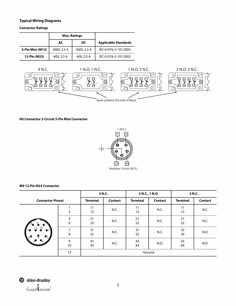
Typical Wiring Diagrams
Connector Ratings
N5 Connector 2-Circuit 5-Pin Mini Connector
M9 12-Pin M23 Connector
Max. Ratings
Applicable StandardsAC DC
5-Pin Mini (M12) 300V, 2.5 A 300V, 2.5 A IEC 61076-2-101:2003
12-Pin (M23) 60V, 2.5 A 60V, 2.5 A IEC 61076-2-101:2003
4 N.C. 1 N.O. 1 N.C. 1 N.O. 3 N.C. 2 N.O. 2 N.C.
Same polarity this side of block
41 31 21 11
42 32 22 12
11 23
12 24
43 31 21 11
44 32 22 12
43 33 21 11
44 34 22 12
1 (N.C.)
Auxiliary Circuit (N.O.)
23
11
24
12
Connector Pinout
4 N.C. 3 N.C., 1 N.O. 3 N.C.
Terminal Contact Terminal Contact Terminal Contact
13
1112
N.C.1112
N.C.1112
N.C.
46
2122
N.C.2122
N.C.2122
N.C.
78
3132
N.C.3132
N.C.3334
N.O.
910
4142
N.C.4344
N.O.4344
N.O.
12 Ground
2
3
45
6
1
11
10
98
712

3
Open Conduit Dimensions [mm (in.)]
60(2.36)
40 (1.57) 43 (1.69)
30 (1.18)
11 (0.43)
211(8.3)
60(2.36)
40 (1.57) 43 (1.69)
30 (1.18)
11 (0.43)
303 (11.92)Extends to900 (35.43)
Max.
10 (0.39)Dia.
60(2.36) 10
3(4
.05)
40 (1.57)
85(3.34)Max.
43 (1.69)
64 (2.51)7 (0.27)
17 (0.66)Dia.
30 (1.18)
16(0.62)
172
(6.7
7)M
ax.E
xten
sion
33 (1.29)
60(2.36)
30 (1.18)
70.5(2.76)
76.5(3.01)
40 (1.57)
48(1.88)
17 (0.66)Dia.
21(0.82)
118(4.64)
43 (1.69)
60(2.36) 133
(5.23)
30 (1.18)
40 (1.57)
63(2.48)
43 (1.69)
64 (2.51)7 (0.27)
18 (0.7)Dia.
67.6(2.66)
8(0.31)Ø 50.0 (1.97)
R 41…76(1.61…2.99)
60 (2.36)
30 (1.18)
40(1.57) 43
(1.69)
85…120(3.35…4.725)
33 (1.29)
60(2.36)
30 (1.18)
40 (1.57)
36.6(1.44)
19(0.74)
43 (1.69)
Roller Plunger
Adjustable Lever
Dome Plunger Short Lever
Spring Rod
103(4.05)
30 (1.18)60
(2.36)
40 (1.57)
5 (0.19)Dia.
43 (1.69)
16(0.62)
33 (1.29)
240 (9.44)Max.
Extension
57 (2.24)
Rod Lever
Telescopic Arm
Adjustable Lever with Rubber Roller

Publication 440P-IN019A-EN-P—10000026105 Ver 03—May 2015Copyright © 2015 Rockwell Automation, Inc. All rights reserved. Printed in the U.S.A.
Rockwell Automation maintains current product environmental information on its website athttp://www.rockwellautomation.com/rockwellautomation/about-us/sustainability-ethics/product-environmental-compliance.page.
Allen-Bradley, Rockwell Software, and Rockwell Automation are trademarks of Rockwell Automation, Inc.Trademarks not belonging to Rockwell Automation are property of their respective companies.