installation and operating instructions … compact space saver: mounts on a wall with two hooks. -...
TRANSCRIPT

WARNING: Improper installation,adjustment, alteration, service or maintenance cancause injury or property damage. Refer to this manual.For assistance or additional information consult aqualified installer, service agency or the gas supplier.Upon completion of the installation, these instructionsshould be handed to the user of the appliance forfuture reference.In the Commonwealth of Massachusetts this productmust be installed by a licensed plumber.
FEATURING: Automatic Variable Power Modulating GasValve, Electronic Ignition and Power Venting
INSTALLATION AND OPERATING INSTRUCTIONS FOR AUTOMATICINSTANTANEOUS TYPE WATER HEATER FOR USE WITH NATURAL ANDLIQUEFIED PETROLEUM GAS
MODEL 125FX LP and 125FX NG(Flow Modulated with Electronic Ignition and Power Venting – a Type III Category Appliance)
Suitable for heating potable water onlyNot approved for space heating purposes
Intended for variable flow applications with steady cold water inlet temperatures
WARNINGIf the information in this manual is not followedexactly. A fire or explosion may result causing propertydamage, personal injury or death.
FOR YOUR SAFETYDo not store or use gasoline or other flammable,combustible or corrosive vapors and liquids in thevicinity of this or any other appliance.
WHAT TO DO IF YOU SMELL GAS- Close gas valve. Open windows.- Do not try to light any appliance.- Do not touch any electrical switch; do not use any
phone in your building.- Immediately call your gas supplier from a neighbor’s
phone. Follow the gas supplier’s instructions.- If you cannot reach your gas supplier, call the fire
department.- Installation and service must be performed by a
qualified installer, service agency or the gas supplier.
Specifications .................................................... Page 2Rules for safe operation .................................... Page 4Locating the Heater ............................................ Page 4Combustion Air Requirements ............................ Page 5Mounting the Heater ........................................... Page 5Venting the Heater ............................................. Page 6Gas Connections ............................................... Page 9Water Connections .......................................... Page 10Electrical Connections ......................................Page 11Safety before turning on the heater ................... Page 12Lighting and Operating instructions .................. Page 12Setting water temperature ................................ Page 12Maintenance & Service..................................... Page 13Trouble Shooting .............................................. Page 14Diagram of AquaStar ......................................... Page 17Components and Parts List .............................. Page 18
TABLE OF CONTENTS
6 72
0 60
6 51
9 (0
2.01
) A
L

2
AquaStar 125FX LP and 125FX NG Specifications
Water Connection 1/2” Thread fitting NPT
H x W x D 29 3/4” x 18 1/4” x 8 3/4"
Vent 4” (Category III Gas Appliance)
Gas Connection 1/2” NPT thread
Min. Water Pressure 18 Psi
Max. Water Pressure 150 Psi
Shipping Weight 50.6 LB
Net Weight 44 LB
2.0 GPM at 90° rise
4.0 GPM at 45° rise
Min. Water Flow 1/2 gal/min
120V/60Hz 1.2 Amps
LP GAS Supply Pressure min. 11” W.C.(before Aquastar regulator) max.14” W.C.*
Required LP GAS pressure at inlettap while Aquastar is operating: 10.5” W.C.
LP GAS Burner Manifold pressure whileAquastar is operating at maximum input: 9.9” W.C.
Natural Gas Supply Pressure(before Aquastar regulator) min.: 7” W.C.
max.: 14”W.C.*
Required Natural Gas Pressure atinlet tap while Aquastar is operating: 5.7”W.C.
Natural Gas Burner Manifold pressure whileAquastar is operating at maximum input: 5.38” W.C.
* Inlet gas pressure before Aquastar regulator must notexceed this value. Pressure may need to be adjusted forhigh altitudes, see page 10.
Principle of Operation:When a hot water faucet is opened, the flow of water throughthe heater causes the gas valve to open. At the same timea microswitch is activated which sends a spark to the pilot.The flame sensor confirms that the pilot has been lightedand allows the first two burners to ignite. The flame sensorconfirms correct activation and all burners ignite. The pilotgoes out. The power exhaust system runs as long as theburners are on. The heat exchanger coils absorb the heatgenerated by the burners and transfer heat to the water.When the hot water faucet is shut off, the gas valveautomatically closes and the burners turn off, followedimmediately by the exhaust system. Your hot water faucetis an ignition key to turn on the water heater, giving youcontrol over your hot water energy use. Every time you turnoff your hot water faucet, the energy consumption for hotwater returns to zero.
FEATURES
- Electronic Pilot Ignition
- On/Off switch to activate system
- Power Venting with safety shutoff
- High Quality Materials for Long Working Life.
- Copper heating coils for endless supply of hot water.
- Burner output proportional to hot water flow demand formaximum energy efficiency.
- Safety flame sensor at pilot burner.
- Automatic overheating protection shut-off sensor.
- Stainless steel burners with stabilized blue flame.
- Built-in corrosion resistant power venter.
- Compact space saver: mounts on a wall with two hooks.
- Easily removable one-piece cover.
- Easy one person installation.
- Adjustable water flow restrictor to ensure that water flowdemand will not exceed the heating capacity of the heater.
UNPACKING THE AQUASTAR HEATER
This heater is packed securely. The box includes two water connection fittings, a control knob, a gas pressure regulator,a pressure relief valve, an incandescent particle tray, two hooks for hanging the heater, this manual, a warranty statementand a warranty registration card. Do not lose this manual as there is a charge for replacement. Please completeand return the enclosed warranty registration card. The FXHOOD horizontal vent terminator is supplied separately fromthe 125FX water heaters. There is a set of installation instructions in the FXHOOD box.
AQ125FXNG AQ125FXLPG
max. 130 000 Btu/hr 125 000 Btu/hr
min. 28 000 Btu/hr 28 000 Btu/hrGas input
BOSCH is constantly improving our products, thereforespecifications are subject to change without priornotice.

3
MINIMUM INSTALLATION CLEARANCES FROM COMBUSTIBLE AND NONCOMBUSTIBLE MATERIALS FOR ALCOVE OR CLOSET INSTALLATIONS
FRONT VIEW SIDE VIEW
AQUASTAR MODEL 125FX
D08
4_08
9
* On a combustible wall surface the unit should be mounted awayfrom the wall to provide adequate clearance of the vent pipe.See page 5 for instructions.** Some local codes require 18” in garage installations
TOP (A) 12 "
FRONT (B) 4 "BACK 0 " *SIDES 4 "
FLOOR (C) 12 " **
VENT DIAMETER 4 "
MODEL 125FX

4
GENERAL RULES TO FOLLOWFOR SAFE OPERATION
1. You should follow these instructions when you installyour heater. In the United States: The installation mustconform with local codes or, in the absence of local codes,the National Fuel Gas Code ANSI Z223.1/NFPA 54.In Canada: The Installation should conform with CGAB149.(1,2) INSTALLATION CODES and /or local installationcodes.
2. Carefully plan where you install the heater. Correctcombustion air supply and flue pipe installation are veryimportant. If not installed correctly, fatal accidents can becaused by lack of air, carbon monoxide poisoning or fire.
3. The place where you install the heater must haveenough ventilation. The National Fire Codes do notallow gas fired water heater installation in bathrooms,bedrooms or any occupied rooms normally keptclosed. See the section below on locating the heater.
4. You must install your heater so that the venting complieswith all requirements. Venting must comply with allrequirements for Category III gas appliances. See sectionon Venting the Heater, pages 6 and 7.
5. The appliance must be disconnected from the gas supplypiping system during any pressure testing at pressures inexcess of 1/2 Psig (3.5 kPa).
The appliance must be isolated from the gas supply pipingduring any pressure testing of the gas supply piping systemat test pressures in excess of 1/2 Psig (3.5Kpa). Theappliance and its gas connection must be leak tested beforeplacing the appliance in operation.
6. Keep water heater area clear and free from combustiblesand flammable liquids. Do not locate the heater over anymaterial that might burn. Do not install heater over carpeting.
7. Correct gas pressure is critical for the optimumoperation of this heater (see specifications on page 2 andchart on page 9). Gas piping must be sized to provide therequired pressure at the maximum output of the heater.Check with your local gas supplier, and see the section onconnecting the gas supply.
8. Should overheating occur or the gas supply fail to shutoff, turn off the gas supply at the manual gas shut off valveon the gas line.
9. Do not use this appliance if any part has been underwater. Immediately call a qualified service technician toinspect the appliance and to replace any part of the controlsystem and any gas control that has been under water.
10.When installed, the appliance must be electricallygrounded in accordance with local codes or, in the absenceof local codes, in accordance with the National ElectricalCode ANSINFPA 70 and/or the CSA 22.1 Electrical Code.
PROPER LOCATION FOR INSTALLINGYOUR HEATER
Carefully select the location of your new heater. For yoursafety and for proper heater operation, you must provide anabundant supply of combustion air and a proper ventinginstallation.
The heater may still operate even when improperly vented.It will, however, be less efficient and could eventually damagethe heater. It could even result in human sickness or deathdue to oxygen deprivation and carbon monoxide poisoning.Before installing the unit, be certain you have the correctheater for your type of Gas – Propane or Natural Gas.Identification labels are found on the shipping box, and onthe rating plate which is located on the right side panel ofthe cover. Also, each burner orifice is stamped with a number(79 for LPG and 120 for Natural Gas).
Follow the guidelines below:
1. National building codes require that you do not installthis appliance in bathrooms, bedrooms, unventedcloset or any occupied rooms normally kept closed.
2. Simultaneous operation of other appliances such asexhaust fans, ventilation systems, clothes dryers, fireplacesor wood stoves could create a vacuum effect in your homewhich could cause dangerous combustion by-products tospill back into your home rather than venting to the outsidethrough the flue. Confirm that your Aquastar is ventingproperly when all these other appliances are running. Seepage 6 to test venting performance.
Do not obstruct the flow of combustion air to theappliance. This appliance is power vented and uses roomair. Note: Electrical power is required to operate the powerexhaust. Proper air supply to the appliance is essential.If installed near a clothes dryer it is very important that thedryer be properly vented. Failure to properly vent a dryercould result in a gradual accumulation of lint on the waterheater fin coils and burners, leading to a dangerouscondition of vent blockage and poor, unsafe combustion.
3. Your hot water lines should be kept short to save energy.It is always best to have hot water lines insulated.
WARNING: DO NOT INSTALL IN AN AREAWHERE IT COULD FREEZE. This heater is neitherdesigned for nor approved for outside installation.Drain the heater entirely if freezing temperatures areanticipated in area where heater is installed bydisconnecting both the inlet and outlet elbow connectionsat the rear of heater. Additionally, remove the drain plugunder the water valve. See Fig 0.”
Fig. 0 - Water heater drain plug
WARNING: Flammable materials, gasoline,pressurized containers, or any other items or articles thatare potentially fire hazards must NOT be placed on oradjacent to the heater. The appliance area must be keptfree of all combustible materials, gasoline and otherflammable vapors and liquids.

5
COMBUSTION AIR REQUIREMENTS
The AquaStar water heater holds cold water in its copperheat exchanger and brass water valve when not in use.Because of this, any cold air that comes in through theunit’s vent pipe is capable of freezing these components.This Installation Manual specifies the vent lengthrequirements and the amount of combustion air requiredfor this unit. When all requirements are followed, the unitwill operate properly and safely. However, there may stillbe a risk of freezing due to negative draft if all the combustionappliances in the area are not being supplied with a sufficientamount of make-up air. A wood stove or furnace can rob themake-up air in the AquaStar’s vent pipe, leaving the coldinfiltrating air capable of freezing the cold water in theAquaStar heat exchanger. To prevent this the FXHOODhorizontal vent terminator, which is supplied separately withthe water heater, needs to be installed on the end of thehorizontal vent run (see page 7). The FXHOOD is a CSAapproved vent terminator for the Aquastar 125FX and has abuilt in back draft flapper.
Observe the following instructions concerning combustionair.
Appliances located in unconfined spaces:a) An unconfined space is one whose volume is greater
than 50 cubic feet per 1000 Btu per hour of the combinedrating of all appliances installed in the space. That wouldbe 6500 cubic feet for the AquaStar 125FX alone.
b) In unconfined spaces in buildings of conventional frame,masonry, or metal construction, infiltration is normallyadequate to provide air for combustion, ventilation, anddilution of flue gasses.
Appliances located in confined spaces: The confined spacemust be provided with two permanent openings, onecommencing within 12 inches of the top and onecommencing within 12 inches of the bottom of theenclosure. Each opening must have a minimum free areaof one square inch per:— 1000 Btu/hr if all air is taken from inside the building.— 2000 Btu/hr if all air is taken from the outside by horizontal
ducts.— 4000 Btu/hr if all air is taken from the outside by direct
openings or vertical ducts.Or the confined space must be provided with one permanentopening or duct that is within 12 inches of the ceiling of theenclosure. This opening must have a minimum free area ofone square inch per:— 3000 Btu/hr if all air is taken from the outside by a direct
opening or vertical duct.Louvers, grills and screens have a blocking effect. If theeffective free area is not known, assume it is 20 % to 25%of the total opening for wood louvers and 60 % to 75% formetal louvers. Refer to the National Fuel Gas Code forcomplete information. In buildings of tight construction allair should be taken from outside.
This product is not approved for manufactured homes(mobile home), recreational vehicles (RV) or boats.Reference ANSI Z21.10.3.This product is neither designed or approved foroutside installations.
CLEARANCES
The Aquastar 125FX is design certified for installation on acombustible wall and for installation in an alcove or closetwith the minimum clearances to combustible and non -combustible construction listed below
A. Top 12 inches (305 mm)B. Front 4 inches (102 mm)C. Back 0 inches*D. Sides 4 inch (102mm)E. Bottom 12 inches (305 mm)**
* On a combustible wall surface the unit should be mountedaway from the wall to provide adequate clearance of thevent pipe. See mounting instructions below.** Some local codes require 18” in garage installations.
Clearance from vent pipe is dependent upon the clearancerating of the venting material used. Single wall flue pipeshould be used and it is approved for 3” clearance for thisappliance. NOTE: See mounting instructions below to prop-erly maintain a 3” clearance from the vent pipe to a com-bustible surface.
Note: this clearance can be reduced if combustible materialare protected as per table VI of the National Fuel Gas Code.
MOUNTING INSTALLATION
The Aquastar 125FX is design certified for mounting on awall.Secure the two L shaped hooks, which are provided withheater, to a wall surface. Place them 13 ¼” apart as shownin Fig 2.Do not install this appliance on a carpeted wall or over floorcovering which is combustible, such as carpet. The heatermust be mounted on a wall using appropriate anchoringmaterials. If wall is a stud wall sheathed with plasterboard,it is recommended that support board(s) either 1x4’s or 1/2" (minimum) plywood first be attached across a pair ofstuds and then the heater should be attached to the supportboards. See Fig 2.NOTE: Additionally the 125FX should be spaced away fromany combustible wall surface by a minimum of 1 ½” toprovide the needed 3” clearance between the vent pipe andthe wall surface. Review the FXHOOD horizontal ventterminator instruction sheet (provided with the FXHOOD)prior to heater installation.In earthquake-prone zones, CEC recommends thatinstallers use a large washer and lag screw through theexisting holes used to hang the heater to affix the upperthird of the heater to the mounting board. To affix the lowerthird of the heater, CEC recommends that two new holesbe drilled in the heater’s frame, each one 16 inches belowthe top two holes, and that washers and lag screws beused to secure the lower portion of the heater to a spacingboard.Expansion and contraction of piping due to changing watertemperature in the pipes imparts movement to the heaterwhich, if mounted directly to a brittle, friable board, suchas plasterboard, can cause failure of mounting.

6
Fig. 3 - Incandescent Particle Tray Illustration
The incandescent particle tray (shipped loose in the cartonwith the water heater) must be attached at the bottom ofthe water heater front cover at the time of installation. Usethe screws provided. See figure 3.
SCREWS
INCANDESCENT PARTICLE TRAY
Fig. 2 - Mounting the Heater
WALL STUDS
1” X 4”SPACE BOARD
SUPPORT BOARD
13 ¼”
VENTING
WARNING: Do not reduce the vent pipe size.This appliance must be vented horizontally to the outsidewith sealed 4” single wall vent pipe following all localordinances and specifications for installing a power ventedCategory III appliance. The 4” single wall vent pipe can beeither stainless steel (AL29-4C) or galvanized vent of atleast 26 gauge. Stainless steel is preferred. All connectionsmust be properly sealed. The vent system must be installedby a qualified installer in accordance with all applicablelocal gas codes. The venting system must be designedand constructed so as to develop a positive flow adequateto remove flue gases to the outdoors.
CAUTION: Aquastar power vent system must be installedby a qualified agency in accordance with these instructions.If improperly installed a hazardous condition such as anexplosion or Carbon Monoxide poisoning could result.Controlled Energy Corporation will not be responsible forimproperly installed appliances.
Plan the vent system so that code and manufacturer’sclearances are maintained.The minimum clearance from the top of the heater is 12inches. Single wall vent pipe when mounted to the 125FXrequires a 3-inch clearance from combustibles. In all cases,follow local codes:- In Canada, CAN/CGA-B149 Installation Code for detailedrequirements.- In USA, ANSI Z223.1 – latest edition, National Fuel GasCode for detailed.
Minimum vent size diameter must be 4”. The appliancemust be located as close as practicable to a vent terminal.Maximum vent length is 15 feet (4.6m) with two 90-degree elbows. This unit may be directly connected toan approved vent termination with a 90-degree elbow. Thevent pipe connections must be secured to each other witha minimum of 4 sheet metal screws per connection, andall seams must be sealed with an approved high temperaturesilicone sealant and aluminum duct tape. The vent systemmust be gas tight. See Fig 4 for suggested ventinginstallation diagrams.
For best results, the horizontal vent system should be asshort and straight as possible. Vent pipe must be singlewall stainless steel (AL29-4C) or galvanized vent pipe of 26minimum gauge. The maximum allowable horizontallength of vent pipe is 15 feet. 2 elbows are allowablewithin this maximum vent length. For each additionalelbow deduct 5 feet from maximum vent length. Anyvertical portion of the vent pipe that is part of thehorizontal vent system must be considered part of theallowable 15 foot maximum. When the horizontal ventrun exceeds 5 feet the following criteria must be observed:
- Support the vent run at 4-foot intervals with overheadhangers.
- Horizontal sections of vent connectors must rise ¼”for every foot of horizontal length. Any vent sectiongreater than 45 degrees from vertical is consideredhorizontal.
Note: Single wall vent pipe cannot be used in anyconcealed locations and should not be used in any unheatedspace without an insulated chase. Unsealed 5” or 6” sizedouble wall B-Vent may be used as a chase for straightlengths (no elbows) of the 4” single wall vent pipe. Allconnections of the 4” single wall vent inside the 5” or 6”B-Vent must be properly sealed. A 1” clearance is requiredfrom the B-Vent pipe to combustibles.
Freeze Warning:As mentioned on Page 5, negative air pressure in coldclimates will cause a reverse airflow in the vent systemthat can freeze and damage the Aquastar heat exchangerwhen not in use. To prevent this the FXHOOD horizontalvent terminator, which was supplied separately with thewater heater, needs to be installed on the end of thehorizontal vent run (see page 7). The FXHOOD is a CSAapproved vent terminator for the Aquastar 125FX and has abuilt in back draft flapper.
Spill Switch Safety:The 125FX is equipped with a Spill Switch; it’s mounted onthe left side of the draft diverter (Flue gas safety device - #9on page 19). Before leaving the installation site verify properSpill Switch operation by temporarily blocking terminationoutlet. Once blocked then operate the heater, the unitshould shut down within 1-3 minutes when the flue gasesare blocked. You must reset the electrical power to theheater after this safety test has been conducted, otherwisethe unit will not operate.

7
Fig 4: Some Venting Guide SuggestionsAn approved side wall vent terminal must be used when the water heater is vented through a sidewall. Locate in accordance with ANSI Z223.1 and local applicable codes. See Fig 5 for restrictionsin location of vent terminal in relation to opening doors and windows, grade, and forced air inlets.Be certain that snow and ice will not interfere with the vent.
Approved Vent Terminal(FXHOOD or other approved terminal)The FXHOOD is design approved with theAquastar 125FX and has a built in back draftflapper to prevent negative air from freezing theAquastar – see Fig. 5 for restrictions in loca-tion of vent terminal.
G18
1_27
4
Approved Vent Terminal(FXHOOD or other approved terminal)The FXHOOD is design approved with theAquastar 125FX and has a built in back draftflapper to prevent negative air from freezing theAquastar – see Fig. 5 for restrictions in loca-tion of vent terminal.
4”single wall venting only. Usestainless steel (AL29-4C) orgalvanized pipe of 26 minimumgauge must be used. Eachconnection must be properlysealed.
4”single wall venting only. Usestainless steel (AL29-4C) orgalvanized pipe of 26 minimumgauge must be used. Eachconnection must be properlysealed.
HORIZONTAL SIDE WALL* Maximum 15 feet with 2 elbows.Deduct 5 feet for each additional elbow.

8
Fig 5: Side wall exit locations for mechanical draft vent terminals
SOFFIT
VENT HOOD
7’ MINIMUM ABOVE
PUBLIC WALKWAY
ONE FOOT
ABOVE GRADE
3’ ABOVE ANY FORCED
AIR INLET W
ITHIN 10’ 4’ MIN
1’ MIN
4’ MIN
4’ MIN
4’ MIN
1’ MIN
VENT HOOD MUST BEMOUNTED FOUR FEET AWAYFROM DOORS AND WINDOWS
VENT HOOD MUSTBE MOUNTED FOUR FEET MINIMUMBELOW WINDOWS
VENT HOOD MUSTBE MOUNTED ONE FOOT MINIMUMABOVE DOORS AND WINDOWS
The approved vent terminal must be installed so that flue gases will not jeopardize people, overheat combustible structuresor enter into buildings, and so that proper clearances are maintained (See Fig 5).
a) The vent terminal shall not be less than 7 feet above a public walkway.b) The vent terminal shall terminate at least 3 feet above any (mechanical) air inlet within 10 feet.c) The vent terminal shall not be within a 6-foot radius from a gas meter or regulator.d) The vent terminal shall be a minimum of 6 feet from any combustion air inlet.e) The vent terminal shall terminate from an opening window, at least 4 feet below or 4 feet horizontally from the
opening.f) The vent terminal shall terminate from a door, at least 1 foot above and 4 feet horizontally from the door.g) The vent terminal shall not be less than 3 feet from an adjacent building.h) The vent terminal shall not be less than 1 foot above grade.

9
GAS PIPING, CONNECTIONS and Gas Regulator
Before connecting the gas supply, check the rating plate on the right side of the front cover to be sure that the heater israted for the same gas to which it will be connected.In the United States: The installation must conform with local codes or, in the absence of local codes, the National FuelGas Code ANSI Z223.1/NFPA 54.In Canada: The Installation should conform with CGA B149 INSTALLATION CODES and /or local installation codes.
FOR NATURAL GASMaximum Capacity of pipe in Cubic Feet of Gas per Hourfor Gas Pressure of 0.5 Psig or less and a Pressure drop of0.3 in Water Column.
Follow boxed numbers for piping just one Aquastar 125FX(example: 3/4” B.I. Natural Gas pipe for 30 ft. will handle152,000 btu’s). For multiple appliances combine the totalbtu input load and then refer to applicable chart below.
(Based on a 0.60 Specific Gravity Gas) Btu numbers givenin thousands.
FOR LP GAS
Maximum Capacity of Pipe in Thousands ofBTU per Hour of Undiluted Petroleum Gases(at 11 inches Water Column Inlet Pressure)(Based on a Pressure Drop of 0.5 Inch WaterColumn).
Maximum Capacity of Semi-RigidTubing in Thousands of BTU per Hour ofUndiluted Liquified Petroleum Gases (at 11inches Water Column Inlet Pressure)
(Based on a Pressure Drop of 0.5 Inch WaterColumn)
* Source National Fuel Gas Code NFPA 54, ANSI Z223.1 - NoAdditional Allowance is necessary for an ordinary number of fittings
GAS LINE SIZING
Nominal
Iron Length of Black Iron Pipe, Feet
Pipe Internal
Size, Diameter
inches inches 10 20 30 40 50 60 70 80 90 100 125 150 175 200
1/4 0.364 32 22 18 15 14 12 11 11 10 9 8 8 7 6
3/8 0.493 72 49 40 34 30 27 25 23 22 21 18 17 15 14
1/2 0.622 132 92 73 63 56 50 46 43 40 38 34 31 28 26
3/4 0.824 278 190 152 130 115 105 96 90 84 79 72 64 59 55
1 1.049 520 350 285 245 215 195 180 170 160 150 130 120 110 100
1 1/4 1.380 1050 730 590 500 440 400 370 350 320 305 275 250 225 210
1 1/2 1.610 1600 1100 890 760 670 610 560 530 490 460 410 380 350 320
2 2.067 3050 2100 1650 1450 1270 1150 1050 990 930 870 780 710 650 610
2 1/2 2.469 4800 3300 2700 2300 2000 1850 1700 1600 1500 1400 1250 1130 1050 980
3 3.068 8500 5900 4700 4100 3600 3250 3000 2800 2600 2500 2200 2000 1850 1700
4 4.026 17,500 12,000 9,700 8,300 7,400 6,80 6,200 5,800 5,400 5,100 4,500 4,100 3,800 3500
Nominal
Iron Pipe Black Iron Pipe
Size, Length of Pipe, Feet
Inches 10 20 30 40 50 60 70 80 90 100 125 150
1/2 275 189 152 129 114 103 96 89 83 78 69 63
3/4 567 693 315 267 237 217 196 185 173 162 146 132
1 107 732 590 504 448 409 378 346 322 307 275 252
1 1/4 220 149 121 103 913 834 771 724 677 630 567 511
1 1/2 330 229 185 155 141 127 118 108 102 976 866 787
2 622 433 346 299 264 239 220 204 192 1811 1606 1496
CopperOutside Length of Tubing, FeetDiameter,Inch 10 20 30 40 50 60 70 80 90 100
3/8 39 26 21 19 _ _ _ _ _ _
1/2 92 62 50 41 37 35 31 29 27 26
5/8 199 131 107 90 79 72 67 62 59 55
3/4 329 216 181 145 131 121 112 104 95 90
7/8 501 346 277 233 198 187 164 155 146 138

10
Fig. 6 - Appliance pressure regulator(with directional arrow on reverse side pointing up)
The pressure regulator provided with the heater is adjustedto deliver the proper gas pressure (as indicated on therating plate and in the manual for altitude up to 2000 feet(660 meters) above sea level. On appliances being installedabove 2000 ft (660 meters) elevation, the inlet gas pressureshould be set at installation to the value shown below.
NOTE: The gas pressures specified below refer topressures taken at the pressure tap on the gas inletpipe just above the regulator (See Fig 6). Thesereadings should be taken while the heater is operatingat full input — i.e. maximum water flow with thetemperature dial selector turned all the wayclockwise.
MAXIMUM INLET PRESSURE SETTINGS
Above 4.500 ft consult your local gas provider.
It is strongly recommended that the natural gas pipe linebe 3/4" for the entire distance. If the maximum length isabove 40 feet, use 1" line. Flexible tubing is NOTrecommended, but if it is to be used, oversize it. With LPgas installation, the recommended sizes are 5/8" up to amaximum of 20 feet distance, 3/4" up to 50 ft distance and7/8" up to 100 feet.
National Fuel Gas Code requires that a sediment trap (dripleg) be installed on gas appliances. The drip leg must beaccessible and not subject to freezing conditions. Install inaccordance with the recommendations of the gas supplier.
NOTE: The AquaStar 125FX is supplied with a gaspressure regulator that must be installed on the heaterbefore attaching the gas supply line. See figure 6.Failure to install the gas regulator as shown in figure6 will be a violation of CSA certification of the unit.The regulator supplied with the heater is preset forthe gas shown on the rating plate to the correctpressure. It is an appliance level regulator designedfor (low inlet) pressure (less than 1/2 Psig or 15” W.C.)DO NOT connect to an unregulated or high pressurepropane line or to a high pressure commercial naturalgas line.
WARNING: The heater must be disconnected fromthe gas supply piping system during any pressure testingof that system at test pressures in excess of .5 psig.The water heater must be isolated from the gas supplypiping system by closing the manual shutoff valve duringany pressure testing of the gas supply piping system attest pressures equal to or greater than .5 psig.The water heater, including the pressure regulator providedwith it, must not be operated at gas supply pressures inexcess of .5 psig. If overpressure has occurred, such asthrough improper testing of the gas lines or malfunction ofthe supply system, the gas valve and regulator must bechecked for safe operation.When your connections are made, check for gas leaks atall joints (not just the ones you made). Apply some soapywater to all gas fittings and gas valve. Soap bubbles area sign of a leak.NOTE: Do not apply soap solution to pilot filter screen orpilot orifice area. If you have a leak, shut off the gas. Afterverifying that required gaskets are in place, tightenappropriate fittings to stop leak. Turn the gas on and checkagain with a soapy solution. Never test for gas leaks usinga match or flame.
WATER CONNECTIONSWhen facing the heater, the cold water inlet is on your rightand the hot water outlet is on your left.Although water piping throughout your structure may beother than copper, we recommend that copper piping beused for at least three feet before and after the heater (followlocal codes if more stringent). Keep water inlet pipe to noless than 1/2 inch diameter to allow the full flow capacity.Remember that water pressure must be sufficient to activatethe heater when drawing hot water from the top floor. If thehot and cold connections to the heater are reversed, theheater will not function. The AquaStar 125FX is providedwith two flexible type connectors that must be connectedto the inlet and outlet fittings of the water valve as shown inFigs 7 and 8. ½” Copper or brass fittings work best whenconnected to the connectors. See Fig 8. These connectorsseal to the water valve by means of a union connectionwith a washer type gasket at the joint. No pipe dope orthread tape is to be used at these joints. Be certain thereare no loose particles or dirt in the piping. Blow out or flushthe lines before connecting to the AquaStar. Full port valvesshould be installed on both the cold water feed line and thehot water outlet line to facilitate servicing the heater.For installation on a private well system, be sure that thewater pressure is set between 30 and 50 psi.
Altitude Natural Gas Liquid Propaneinches W.C: inches W.C:
0' - 2.000 ft 5.38 9.9
2.000 ft - 4.500 ft 4.40 7.90
GAS INLET PIPE
PRESSURE TAP
APPLIANCE PRESSUREREGULATOR(with directional arrow onreverse side pointing upward)
PLASTIC CAP
Fig.7 - Water valve and water connectors, top view
WASHER
WATER FILTER
WATER VALVE
WASHER
INLET
OUTLET
FLEXCONNECTORS

11
- Typical setups are shown below with the pressure reliefvalve attached. The pressure relief valve is supplied withthe heater, and should only be fitted on the hot wateroutlet as shown. The cold water inlet setup will beidentical to diagrams below but without the pressure reliefvalve.
- For ease of installation the piping setup should beprepared as one whole piece with either threaded orsweated connections. The entire assembly will thenmount easily against a wall and to the back of theAquastar.
THREADED ASSEMBLY
Connecting the pressure relief valve (PRV)
The listed pressure relief valve supplied with the heater mustbe installed at the time of installation. Should a dischargeline be added to the PRV no valve is to be placed betweenthe PRV and the heater. No reducing coupling or otherrestriction may be installed in the discharge line. Thedischarge line must be installed such that it allowscomplete drainage of both the PRV and the line. The locationof the PRV must be readily accessible for servicing orreplacement. and be mounted as close to the water heateras possible. To install the PRV, a suitable fitting connectedto an extension on a “T” fitting can be sweated to the hotwater line. See Fig 9.
Fig. 8 - Plumbing connections for the Aquastar 125FX
SWEATED ASSEMBLY
HW
SH
WS
CW
SC
WS
PressureReliefValve
PressureReliefValve
Fig. 9 - Pressure Relief Valve
ELECTRICAL CONNECTIONS
WARNING: This heater must be electrically grounded in accordance with the most recent edition of the NationalElectrical Code, NFPA 70. In Canada, all electrical wiring to the heater should be in accordance with local codes and theCanadian Electrical Code, CSA C22.1 Part 1. Do not rely on the gas or water piping to ground the metal parts of theheater.CAUTION: Label all wires prior to disconnection when servicing controls. Wiring error can cause improper and dangerousoperation. Verify proper operation after servicing.The AquaStar 125FX requires an electrical power supply from 120VAC 60Hz circuit and must be properly grounded.- A means for switching off the 120 VAC power supply must be provided.- The heater is wired as shown in the wiring diagram. (Fig 10).
Fig 10: Wiring Diagram for AQ 125FX
9 - ionization probe (flamesensor)
10 - pilot electrode11 - pilot electrovalve12 - Diaphragm switch13 - burner electrovalve14 - power cord
1 - microswitch2 - electric control box3 - exhaust fan4 - fuse5 - circuit interrupter6 - electronic control box7 - temperature limiter8 - sensors of exhaust gases
E86
4_02
0
PIPE PRV TOAPPROPRIATEDISCHARGE
1/2” FLEX
PIPE PRV TOAPPROPRIATEDISCHARGE
1/2” FLEX

12
6. Turn the hot water faucet on to the minimum flow requiredto activate the heater. The automatic ignition systemfirst ignites the safety pilot burner which then ignites themain burner in about 4 seconds. The power exhaust willthen activate.
7. The pilot flame will extinguish 10-30 seconds after theburners come on. The burners will remain on until thehot water tap is turned off.
NOTE: On a first time installation, existence of air in thegas supply line and in the water line may cause someignition delay. In that case, repeatedly open and close thehot water tap in order to restart the ignition process until allthe air has been purged.
TO TURN OFF GAS TO APPLIANCE
Turn off the manual lever on the gas supply line to the heaterand set the ON/OFF switch to the OFF ( 0 ) position, seeFig. 11.
SETTING THE WATER TEMPERATURE
The AquaStar 125FX LP and 125FX NG water heaters havea gas control that modulates burner input in response toflow. Its purpose is to ensure that the hot water temperaturewill remain steady, although the demand for water flowmight vary (down to 1/2 gal/minute). To adjust thetemperature on your AquaStar, turn on a hot water faucetto its maximum flow. At the AquaStar, turn the large knoblocated beneath the main gas controls on the front of theheater all the way to the right (clockwise). See Fig 12. Thiswill produce a temperature rise of approximately 90°F atflow rates between .5 and 2.0 gallons per minute. Giventhat average incoming water temperatures are 50°F, thisheater will produce approximately 140°F water at theseflow rates. Turning the dial all the way to the left(counterclockwise) will produce a temperature rise ofapproximately 45°F for flow rates between 1.0 and 4.0gallons per minute. This will result in a higher flow rate, butat cooler temperatures. Turning the dial to locations in
OPERATING INSTRUCTIONS
Before operating the heater, make sure that the system isfilled with water.
Open the cold water inlet supply to the heater fully.Open a hot water faucet to permit the water to fill the heaterand the piping and to eliminate the air trapped in the systemClose the hot water faucet after the water flows freely andall the air has escaped from the system. The water heateris now ready to operate.
FOR YOUR SAFETY READ BEFOREOPERATING YOUR HOT WATER HEATER
Warning: If you do not follow these instructionsexactly, a fire or explosion may result causing propertydamage, personal injury or loss of life.
A. This appliance is equipped with electronic ignition forlighting the pilot and main burners. When turning the heateron, follow these instructions exactly.B. Before operating the unit, set the On/Off switch to theOn (I) position. The On/Off switch is located behind theflip-down coverplate on the front panel strip. Smell all aroundthe appliance area for gas. Be sure to smell next to thefloor because some gas is heavier than air and will settleon the floor.
WHAT TO DO IF YOU SMELL GAS- Do not try to light any appliance.- Do not touch any electric switch; do not use any phone
in your building.- Immediately call your gas supplier from a neighbor’s
phone. Follow the gas supplier’s instructions.- If you cannot reach your gas supplier, call the fire
department.
C. Use only your hand to push in the on/off control button.Never use tools. Follow these instructions exactly. If controlbutton is jammed, close the gas supply and call a qualifiedservice technician. Attempted forceful repair may result ina fire or explosion.D. Do not use this appliance if any part has been underwater. Immediately call a qualified service technician toinspect the appliance and to replace any part of the controlsystem and any gas control which has been under water.
LIGHTING AND OPERATING INSTRUCTIONS
1. STOP! Read the safety information on the front panel ofthe heater.
2. The gas valve must be turned off by putting the On/Offswitch to position “O” (see fig. 12). Wait five (5) minutesto clear out any gas. If you smell gas, STOP! Follow “B”in the safety information above. If you don’t smell gas,go to next step.
3. This water heater is equipped with a safety pilot burnerand an automatic ignition control system.
4. Set the ON/OFF switch (flip down cover plate on frontpanel strip) marked I/O to the I position. In this positionthe water heater is ready to use.
5. Verify that the power supply to the appliance is turnedon.
To operate the heater, set the ON/OFF switch to position I.The switch is located behind the flip down cover plate onthe front panel strip.To shut down the gas to the heater, set the ON/OFF switch toposition 0
G66
7_09
1
G66
1_00
4
Temperature Adjustment Knob
Decreasetemperature andincrease flow
Increases temperatureand decreases flow
Fig. 11 - Principles of Operation

13
Fig. 13 - Characteristic Pilot Flame
Flame sensor
PiezoElectrode
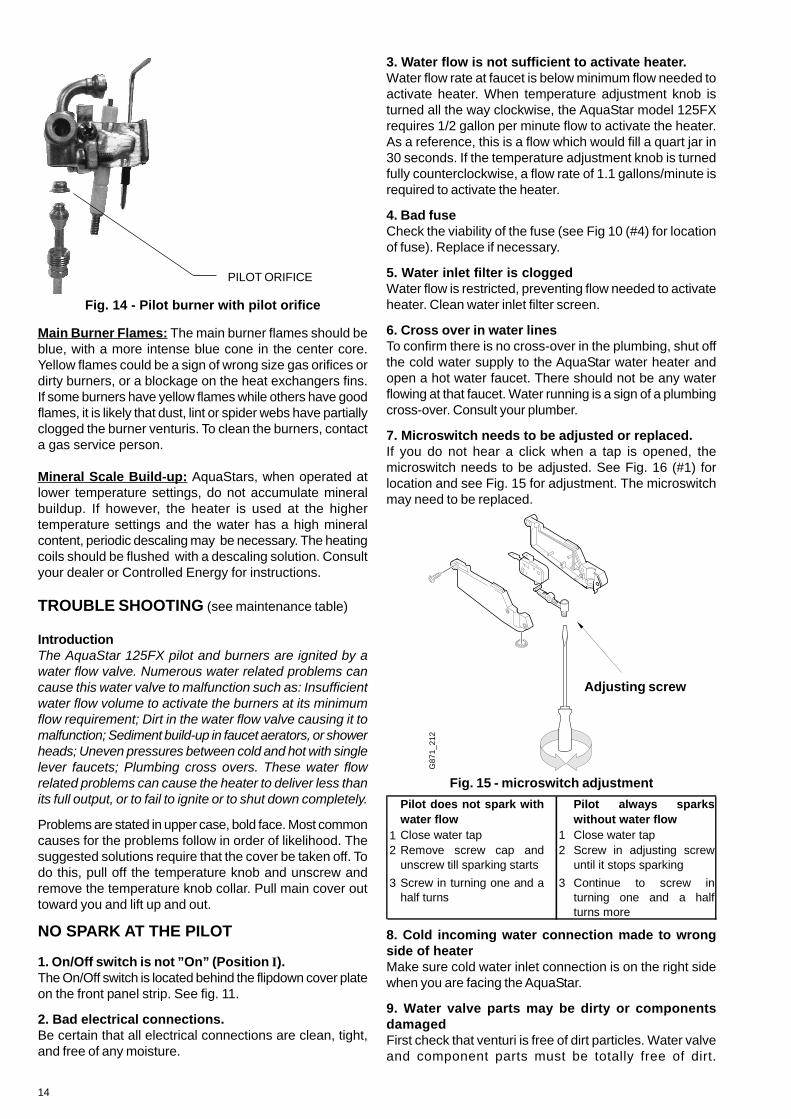
Pilot Flame: The pilot flame should burn with a clean,sharp, blue flame and should resemble the diagram in Fig.13. If the flame is soft and yellow, the pilot burner orificemay need to be cleaned or replaced. The pilot flame shouldbe approximately 2 inches long, extending past the flamesensor. If the flame is too small, it will not reach the flamesensor and the burners will not come on.
3mm
Correct gap between pilotburner tip and electrode tip
Piezo Electrode
To clean the pilot burner and/or the pilot orifice: Turnoff the gas at the unit (Position ‘O’). Remove the cover ofthe heater. To do so, pull off the temperature knob andunscrew and remove the temperature knob collar. Pull maincover out toward you and lift up and out. The pilot orificesshould also be cleaned or replaced. Do not enlarge theorifice (see fig. 14). Do not use any wire or sharp objectto clean orifices. Natural gas orifices are large enough thatyou can usually clean them by blowing through them. LPorifices, on the other hand, are too small to clean and shouldbe replaced. See #3 in Trouble Shooting Section. To accessthe pilot orifice, remove 2 screws holding pilot assembly inplace. Then loosen the compression fitting and lift up pilotburner to expose pilot orifice.
Fig. 12 - Temperature Adjustment Knob
TEMPERATUREADJUSTMENT KNOB
between will give various temperatures between 140° and95°F at various flow rates between 2.0 and 4.0 gallons perminute. The position you select on the temperature selectordial will depend on the temperature of the incoming water(50°F is average in the U.S.). In warm weather regions wherethe incoming cold water is generally warmer, or during thehot weather months in some other areas a midway settingon the temperature selector knob will produce atemperature rise of about 70°F, giving an output ofapproximately 120°F. At this setting, if it is still necessary,one could mix a small amount of cold water in a showerand have a comfortable shower at about 3 gallons/minute.During the colder months, or in cold climate areas, it mightbe necessary to set the control all the way clockwise tothe right for maximum temperature rise.Do not supply the AquaStar 125FX with preheated water.For this type of application, purchase a solar model 125 BLPS or 125 B NGS.
MAINTENANCE AND SERVICE
REVIEW MAINTENANCE TABLE ONTHE BACK OF THIS MANUALApproximately once a year, the AquaStar should be checkedand cleaned. To remove the front cover, first remove theincandescent particle tray, then pull off the temperatureadjustment knob and unscrew and remove the plastic collar.Unscrew the central screw located at the bottom of thefront cover. Pull main cover out toward you and lift up andout. THE FOLLOWING OPERATIONS SHOULD BEPERFORMED BY A QUALIFIED SERVICE PERSON:
Vent System: Should be checked annually. Clean and repairas needed.
Water Valve (Part # 87070024534): The water valve onthis heater should be serviced periodically. Lubricatecomponent #33 on page 19 with a small amount of silicon,faucet or lithium grease every two years to keep its o ringsfresh and pushrod sliding smoothly. Every 3-5 years replacecomponents #33 and #34 on page 19. The frequency willdepend on the mineral content of the water and conditionsof use or whenever signs of corrosion appear at the gasand water valve joint. Periodically check that the water inletfilter (#36 on page 19) is clean as well.
14
3. Water flow is not sufficient to activate heater.Water flow rate at faucet is below minimum flow needed toactivate heater. When temperature adjustment knob isturned all the way clockwise, the AquaStar model 125FXrequires 1/2 gallon per minute flow to activate the heater.As a reference, this is a flow which would fill a quart jar in30 seconds. If the temperature adjustment knob is turnedfully counterclockwise, a flow rate of 1.1 gallons/minute isrequired to activate the heater.
4. Bad fuseCheck the viability of the fuse (see Fig 10 (#4) for locationof fuse). Replace if necessary.
5. Water inlet filter is cloggedWater flow is restricted, preventing flow needed to activateheater. Clean water inlet filter screen.
6. Cross over in water linesTo confirm there is no cross-over in the plumbing, shut offthe cold water supply to the AquaStar water heater andopen a hot water faucet. There should not be any waterflowing at that faucet. Water running is a sign of a plumbingcross-over. Consult your plumber.
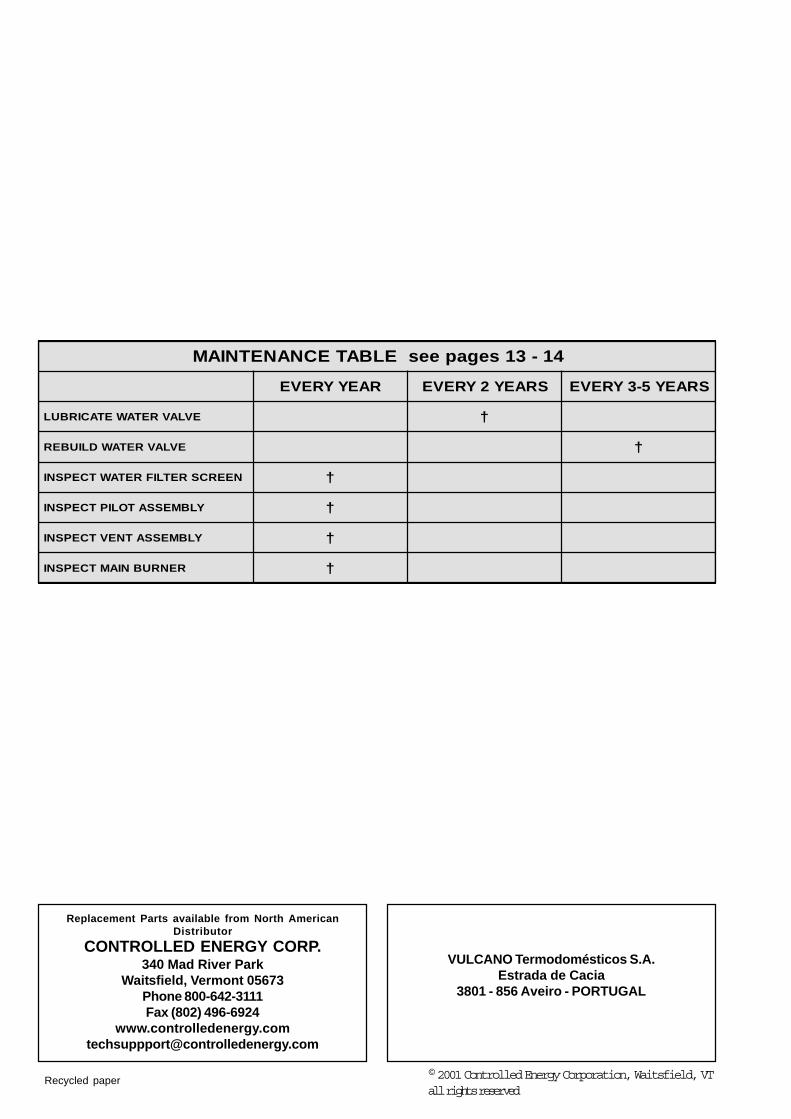
7. Microswitch needs to be adjusted or replaced.If you do not hear a click when a tap is opened, themicroswitch needs to be adjusted. See Fig. 16 (#1) forlocation and see Fig. 15 for adjustment. The microswitchmay need to be replaced.
G87
1_21
2
Adjusting screw
Fig. 15 - microswitch adjustment
Main Burner Flames: The main burner flames should beblue, with a more intense blue cone in the center core.Yellow flames could be a sign of wrong size gas orifices ordirty burners, or a blockage on the heat exchangers fins.If some burners have yellow flames while others have goodflames, it is likely that dust, lint or spider webs have partiallyclogged the burner venturis. To clean the burners, contacta gas service person.
Mineral Scale Build-up: AquaStars, when operated atlower temperature settings, do not accumulate mineralbuildup. If however, the heater is used at the highertemperature settings and the water has a high mineralcontent, periodic descaling may be necessary. The heatingcoils should be flushed with a descaling solution. Consultyour dealer or Controlled Energy for instructions.
TROUBLE SHOOTING (see maintenance table)
IntroductionThe AquaStar 125FX pilot and burners are ignited by awater flow valve. Numerous water related problems cancause this water valve to malfunction such as: Insufficientwater flow volume to activate the burners at its minimumflow requirement; Dirt in the water flow valve causing it tomalfunction; Sediment build-up in faucet aerators, or showerheads; Uneven pressures between cold and hot with singlelever faucets; Plumbing cross overs. These water flowrelated problems can cause the heater to deliver less thanits full output, or to fail to ignite or to shut down completely.
Problems are stated in upper case, bold face. Most commoncauses for the problems follow in order of likelihood. Thesuggested solutions require that the cover be taken off. Todo this, pull off the temperature knob and unscrew andremove the temperature knob collar. Pull main cover outtoward you and lift up and out.
NO SPARK AT THE PILOT
1. On/Off switch is not ”On” (Position I).The On/Off switch is located behind the flipdown cover plateon the front panel strip. See fig. 11.
2. Bad electrical connections.Be certain that all electrical connections are clean, tight,and free of any moisture.
Fig. 14 - Pilot burner with pilot orifice
PILOT ORIFICE
Pilot does not spark withwater flow
Pilot always sparkswithout water flow
1 Close water tap 1 Close water tap2 Remove screw cap and
unscrew till sparking starts2 Screw in adjusting screw
until it stops sparking
3 Screw in turning one and ahalf turns
3 Continue to screw inturning one and a halfturns more
8. Cold incoming water connection made to wrongside of heaterMake sure cold water inlet connection is on the right sidewhen you are facing the AquaStar.
9. Water valve parts may be dirty or componentsdamagedFirst check that venturi is free of dirt particles. Water valveand component parts must be totally free of dirt.

15
Mineral deposits can eventually (3-5 years in hard waterareas) corrode the water valve parts to a point where theywill need replacing. Any sign of moisture at the bleedhole is a sign that the water valve needs to bereplaced immediately.
10. Loose connection at the ECOIgnition sparker will not operate if the electrical circuit isinterrupted. Check that the connections to the ECO aresecure and tighten if necessary.
11. Reset electrical power to heaterIf resetting the electrical power corrected the symptom thenlikely the unit’s Safety Spill switch (Flue gas safety device- #9 on page 19) had tripped from a flue blockage duringthe previous usage. Inadequate combustion air to the roomarea can also cause the unit to improperly vent. Improperventing or insufficient combustion air must be corrected.Consult a licensed professional to inspect the installation.
SPARKS APPEAR AT PILOT WHEN HOT WATER TAPIS TURNED ON, BUT PILOT AND BURNERS WILL NOTIGNITE
1. Air in the Gas LineNote: Normally this is a problem only at the time of initialinstallation, after the pipes have been worked on, or after apropane tank has been allowed to empty, or after the heaterhas been shut down for a long time.Bleed all the air trapped in the gas line by turning the hotwater faucet on and off until the air has been cleared fromthe line.
2. No gas to the AquaStarA. Gas cock on gas line may not be openB. Gas regulator may be shut or damaged. Replace orunlock the regulator. Note: The regulator furnished with theheater is exclusively designed for low gas pressure (lessthan ½ psig). Excessive pressure will lock it up. Lockingusually happens when the gas pressure between the gastank and the water heater’s gas regulator has not beenproperly regulated. See Page 2 for recommended correctgas pressure. To unlock a regulator, consult your gas supplieror call CEC.
3. Pilot orifice clogged or gas valve is dirtyClogging of the pilot burner can be caused by dust in theair or dirt in the gas. The pilot orifice or gas filter may needto be cleaned or replaced. See Fig. 14.
4. Water valve assembly needs to be checkedIf the pilot orifice is clean, the water valve assembly shouldbe checked. The adjustment screw on the water valve micro-switch may not be tight enough (fig. 15). Remove centralcap beneath micro-switch assembly, carefully loosen theadjustment screw until the pilot light ignites. At that pointretighten the screw one and a half turns. See Fig 15.
5. Pilot electrovalve switch may need to be replaced(See Fig 10).Call CEC.
6. Electronic Control Box may need to be replaced(See Fig 10).Call CEC.
PILOT SPARKS CONTINUOUSLY WITH NO WATERRUNNING
1. Microswitch needs adjustmentIf no water is running, but pilot electrode continuouslysparks, the microswitch screw to the water valve needsadjustment. See Figure 15.
PILOT LIGHTS BUT BURNERS WILL NOT COME ON
1. Confirm the flame sensor is in its proper position.(see Fig. 13).
2. Sensors for exhaust gases may be loose.The burners will not come on if the powered fan exhaust isnot working. Check that the unit is plugged in and that thesensors for the flue gases are secure.
3. Confirm the ECO connections are secure.
4. The Electronic Control Box (Fig 10) may need to bereplaced.
5. Burner electrovalve switch may need to be replaced(see Fig. 10).
MAIN BURNERS GO OUT DURING HOT WATER USE
1. Deficient exhaustion of flue gasesCheck that vent is correct and clear of any obstructions,that sensors for flue gases are secure and that electricalconnection has been made. If the heater will not come backon, it will be necessary to turn the electrical supply tothe heater off and then on again.
2. Flow rate diminished below activation rateBe certain that water flow is not less than required amountto activate heater.
3. Unbalanced pressure in waterlinesThe added restriction caused by the Aquastar in the hotwater system can result in uneven pressures between thecold and the hot. In such cases when mixing cold water atthe tap, the lower hot water pressure may be overpoweredby a much higher cold water pressure, which may causethe Aquastar burners to shut down (deactivate). Make surefaucet aerators or shower heads are free of minerals.Do not add any flow restrictor to the shower head.Typically this deactivation symptom is a result of thehot water being too hot to use comfortably. Warm inletwater generally causes this. Lowering the controlknob setting and/or reducing the inlet gas supply tothe heater should correct this deactivation symptom.
4. ECO (overheat sensor) tripped due to overheatingDo not feed preheated water to this water heater.
5. Minimum inlet pressure on well pressure tank isinadequate
Check the inlet water pressure. On a private well, raise theminimum pressure setting to 30 psi. Confirm that thepressure tank is not water logged.

16
WATER IS TOO HOT
1. Temperature Selection too highTurn the temperature adjustment knob counter-clockwise(to the left) to lower the maximum water temperature.Note: This will increase the activation flow rate.
2. Inlet water temperature is very warm (60º-75ºF)Reduce inlet gas supply to lower the heaters degree rise.Note: Only the Model 125BS should be used if the inletwater is preheated.
3. Inlet filter screen is clogged, restricting flowRemove screen and clean it.
WATER IS NOT HOT ENOUGH
1. Temperature selection is set too low.Change the setting. Turn the temperature selector knobclockwise (to the right). Note: this will decrease theactivation flow rate.
2. Water flow through the heater is higher than thecapacity of the AquaStar to heat it
Reduce the flow demand at the faucet. See flow rates atspecific temperatures on page 2.
3. Gas pressure is insufficientIt is extremely important for a tankless instantaneouswater heater to have the right size gas line to obtainthe correct gas pressure. See specifications on page 2.Unlike storage tank water heaters, the burners of a tanklesswater heater must be very powerful to heat waterinstantaneously since they do this only at the time hotwater is actually being used. It is therefore imperative thatthe gas pressure requirement be met exactly. Insufficientgas pressure will directly affect the water temperature atthe time of usage. See page 2 for correct gas pressuresettings and see page 9 for proper gas line sizing.
4. Gas supply is insufficientMake sure your main gas line is fully opened. If using LPgas, be sure that the size of the propane tank is adequateto supply the required gas pressure. See gas pipe sizingchart on page 9.
5. Cold water is mixing with the hot water betweenthe AquaStar and the outlet
Compare water temperature at outlet of the AquaStar (holdthe AquaStar’s outlet pipe with your hand) and at the tap.If these two are very different, check for mixing valve orplumbing crossover (see “NO SPARK AT THE PILOT”paragraph 4). Where automatic “anti-scald” valves arerequired by code, lower the temperature setting on theAquaStar as much as possible and balance the pressurebetween cold and hot water after the AquaStar.
6. Gas valve above the water valve is not fullyopening.If the internal water valve parts are damaged from waterquality or use, or there is evident corrosion where the watervalve and gas valve connect, then immediate service isneeded. See step 9 under the problem NO SPARK AT THEPILOT. White vinegar should be applied first to any corrosionbefore the loosening of screws.
HOT WATER TEMPERATURE FLUCTUATES /UNIT DEACTIVATED
1. Unbalanced pressure in waterlinesThe added restriction caused by the Aquastar in the hotwater system can result in uneven pressures between thecold and the hot. In such cases when mixing cold water atthe tap, the lower hot water pressure may be overpoweredby a much higher cold water pressure, which may causethe Aquastar burners to shut down (deactivate). Make surefaucet aerators or shower heads are free of minerals.Do not add any flow restrictor to the shower head.Typically this deactivation symptom is a result of thehot water being too hot to use comfortably. Warm inletwater generally causes this. Lowering the controlknob setting and/or reducing the inlet gas supply tothe heater should correct this deactivation symptom.
2. Cold water is mixing with the hot water betweenthe AquaStar and the outletSee #4 under “NO SPARK AT THE PILOT”.
3. Inlet water pressure is erratic due to inadequatesupply water pressure or saturated pressure tank onwell systemCheck the inlet water pressure. On a private well, raiseminimum pressure setting to 30 psi. Confirm that thepressure tank is not water logged.
4. Gas pressure is too lowSee page 2 for correct specifications.
EXHAUST FAN DOES NOT OPERATE
1. Check the fuse (see fig 10)
2. Check all electrical connections
3. Check adjustment of fan microswitch
FAN CIRCULATES WHEN HOT WATER IS SHUTOFF
1. Check adjustment of fan microswitch

17
5
11
1
4
9
10
12
2
6
8
Fig. 17 - Diagram of AquaStar 125FX
1. Heat exchanger2. Pilot assembly3. Burner manifold gas
pressure test nipple4. Main gas burner5. Pilot gas tubing6. Gas valve7. Electronic control box
8. Power cord9. on/off switch
10. Temperature adjustment selector11. Microswitch12. Gas inlet gas pressure test nipple13. Electric box14. Exhaust Fan
7
13
14
3

18
Fig. 18INTERIOR COMPONENTS DIAGRAM
AND PARTS LIST 125FX
1 Front Cover 8 705 421 2552 AquaStar Decal 8 701 103 0743 Plastic lower snap-on 8 705 506 4514 Temperature adjustment knob complete 8 702 000 2195 Temperature adjustment knob 8 702 000 1116 Exhaust fan assembly 8 707 204 0237 Draft diverter 8 705 505 4518 Fan protection 8 701 302 1649 Flue gas safety device 8 707 206 185
10 Heat Exchanger 8 705 406 23511 Hot water pipe 8 700 705 55612 Washer 8 710 103 04513 Overheat sensor (ECO) 8 707 206 04014 Cold water pipe 8 700 705 29415 Main burner assembly 8 708 120 298 NG
8 708 120 296 LP16 Washer for burner assembly 8 710 103 06017 Throttle disc 8 700 100 189 LP only18 Gas Valve 8 707 011 811 NG
8 707 011 812 LP19 Diaphragm switch 8 708 504 021 NG
8 708 504 049 LP20 Burner electrovalve 8 708 501 25021 Pilot electrovalve 8 708 501 24922 O-ring 8 700 205 12023 Electrode ignition group 8 718 107 06724 Pilot burner assembly 8 708 105 337 NG
8 708 105 491 LP25 Injector pilot 8 708 200 069 NG
8 708 200 312 LP26 Pilot gas tube 8 700 707 34927 Washer 8 700 103 17328 Electronic control box 8 707 207 01129 Electric control box 8 707 101 02130 On/Off switch 8 707 200 01431 Microswitch 8 707 200 00732 Water valve 8 707 002 53433 Water valve repair kit 8 703 406 17834 Slow ignition valve 8 708 503 06335 Diaphragm 8 700 503 05336 Water inlet filter 8 700 507 05937 Selector screw 8 708 500 25138 Volumetric water governor 8 707 402 01539 Venturi 8 708 205 24940 Water connections gasket 8 710 103 04341 Water elbow fitting 8 700 703 114

19
Fig. 18 - INTERIOR COMPONENTS DIAGRAM AND PARTS LIST
Replacement Parts available from North AmericanDistributor
CONTROLLED ENERGY CORP.340 Mad River Park
Waitsfield, Vermont 05673Phone 800-642-3111Fax (802) 496-6924
VULCANO Termodomésticos S.A.Estrada de Cacia
3801 - 856 Aveiro - PORTUGAL
41-31segapeesELBATECNANETNIAM
RAEYYREVE SRAEY2YREVE SRAEY5-3YREVE
EVLAVRETAWETACIRBUL †
EVLAVRETAWDLIUBER †
NEERCSRETLIFRETAWTCEPSNI †
YLBMESSATOLIPTCEPSNI †
YLBMESSATNEVTCEPSNI †
RENRUBNIAMTCEPSNI †
Recycled paper © 2001 Controlled Energy Corporation, Waitsfield, VTall rights reserved