installation and operating instructions - buschvacuum.com · 79689 maulburg deutschland 0870145123...
TRANSCRIPT

Installation and Operating Instructions
Side Channel Blowers
Samos SB 0050 - 1400 D0/D2
Busch Produktions GmbH
Schauinslandstr. 1 79689 Maulburg
Deutschland
0870145123 / 091130/ Original instructions / Modifications reserved

Table of ContentsPreface . . . . . . . . . . . . . . . . . . . . . . . . . . . . . . . 2Technical Data . . . . . . . . . . . . . . . . . . . . . . . . . . . 2Product Description. . . . . . . . . . . . . . . . . . . . . . . . . 3
Use . . . . . . . . . . . . . . . . . . . . . . . . . . . . . . . . 3Principle of Operation . . . . . . . . . . . . . . . . . . . . . . 3Cooling . . . . . . . . . . . . . . . . . . . . . . . . . . . . . . 3Start Controls. . . . . . . . . . . . . . . . . . . . . . . . . . . 3
Safety . . . . . . . . . . . . . . . . . . . . . . . . . . . . . . . . 3Intended Use . . . . . . . . . . . . . . . . . . . . . . . . . . . 3Safety Notes . . . . . . . . . . . . . . . . . . . . . . . . . . . 3Noise Emission . . . . . . . . . . . . . . . . . . . . . . . . . . 4
Transport . . . . . . . . . . . . . . . . . . . . . . . . . . . . . . 4Transport in Packaging . . . . . . . . . . . . . . . . . . . . . . 4Transport without Packaging . . . . . . . . . . . . . . . . . . . 4
Storage . . . . . . . . . . . . . . . . . . . . . . . . . . . . . . . 4Short-term Storage . . . . . . . . . . . . . . . . . . . . . . . . 4Conservation . . . . . . . . . . . . . . . . . . . . . . . . . . . 4
Installation and Commissioning . . . . . . . . . . . . . . . . . . 5Installation Prerequisites . . . . . . . . . . . . . . . . . . . . . 5
Mounting Position and Space . . . . . . . . . . . . . . . . . 5Suction Connection/Gas Inlet . . . . . . . . . . . . . . . . . 5Gas Discharge . . . . . . . . . . . . . . . . . . . . . . . . . 5Pressure Connection . . . . . . . . . . . . . . . . . . . . . . 6Electrical Connection / Controls . . . . . . . . . . . . . . . . 6Controlling Pressure/Flow . . . . . . . . . . . . . . . . . . . 6
Installation . . . . . . . . . . . . . . . . . . . . . . . . . . . . 6Mounting . . . . . . . . . . . . . . . . . . . . . . . . . . . 6Connecting Electrically . . . . . . . . . . . . . . . . . . . . . 6
Connection Scheme Alternating Current Motor . . . . . . . 6Connection Scheme Three-Phase Motor. . . . . . . . . . . 7
Connecting Lines/Pipes . . . . . . . . . . . . . . . . . . . . 7Recording of Operational Parameters . . . . . . . . . . . . . 7
Operation Notes . . . . . . . . . . . . . . . . . . . . . . . . . 7Use . . . . . . . . . . . . . . . . . . . . . . . . . . . . . . 7
Maintenance . . . . . . . . . . . . . . . . . . . . . . . . . . . . 8Maintenance Schedule . . . . . . . . . . . . . . . . . . . . . . 8
Monthly: . . . . . . . . . . . . . . . . . . . . . . . . . . 8Every 6 Months: . . . . . . . . . . . . . . . . . . . . . . 8Every Year: . . . . . . . . . . . . . . . . . . . . . . . . . 8
Overhaul . . . . . . . . . . . . . . . . . . . . . . . . . . . . . . 8Removal from Service. . . . . . . . . . . . . . . . . . . . . . . . 9
Temporary Removal from Service. . . . . . . . . . . . . . . . . 9Recommissioning . . . . . . . . . . . . . . . . . . . . . . . . . 9Dismantling and Disposal . . . . . . . . . . . . . . . . . . . . . 9
Spare Parts . . . . . . . . . . . . . . . . . . . . . . . . . . . . . 9Troubleshooting . . . . . . . . . . . . . . . . . . . . . . . . . . 10Exploded Views . . . . . . . . . . . . . . . . . . . . . . . . . . 13EC-Declaration of Conformity . . . . . . . . . . . . . . . . . . . 19Busch – All over the World in Industry . . . . . . . . . . . . . . 20
Preface SB 0050 - 1400 D0/D2
page 2 0870145123 / 091130
PrefaceCongratulations on your purchase of the Busch side channel blower.With watchful observation of the field’s requirements, innovation andsteady development Busch delivers modern vacuum and pressure solu-tions worldwide.
These operating instructions contain information for
– product description,
– safety,
– transport,
– storage,
– installation and commissioning,
– maintenance,
– overhaul,
– troubleshooting and
– spare parts
of the side channel blower.
For the purpose of these instructions, “handling” the side channelblower means the transport, storage, installation, commissioning, influ-ence on operating conditions, maintenance, troubleshooting and over-haul of the side channel blower.
Prior to handling the side channel blower these operating instructionsshall be read and understood. If anything remains to be clarifiedplease contact your Busch representative!
Keep these operating instructions and, if applicable, other pertinentoperating instructions available on site.
Technical DataMotor connection parameters, nominal speeds and allowed differentialpressures are given on the nameplate of the side channel blower. Moretechnical data, available sizes, versions and accessories are given in thecurrent sales programme. In case of further questions please contactyour Busch representative!

Product DescriptionUseThe side channel blower is intended for
– the suction
– the compression
of
– air and other dry, non-aggressive, non-toxic and non-explosivegases
Conveying media with a lower or higher density than air leads to an in-creased thermal and/or mechanical load on the side channel blowerand is permissible only after prior consultation with Busch.
The gas shall be free from vapours that would condensate under thetemperature and pressure conditions inside the side channel blower.
The side channel blower is intended for the placement in a non-poten-tially explosive environment.
The side channel blower is suitable for continuous operation, providedthat the housing can transmit heat to the environment without ob-struction and a certain minimum gas transfer is warranted. If there is arisk that the side channel blower may be operated against a closed inletor outlet for more than a few seconds, a vacuum or pressure reliefvalve, respectively, shall be provided. Frequent switching on and offleads to increased coil temperatures. In case of doubt seek advice fromyour Busch representative!
The nominal value (=reference value for performance data) for thetemperature of the process gas is 15 °C. The max. allowed temperatureof the inlet gas is 40 °C.
The nominal value for the ambient temperature is 25 °C. The min. al-lowed ambient temperature is -30 °C. The max. allowed ambient tem-perature is 40 °C.
Binding data with regard to the allowed differential pressure are to beread from the nameplate (value with negative sign (“-”) for vacuumoperation, value without sign for pressure operation). The data is validfor ambient temperatures up to 25 °C and location altitudes up to1000 m above sea level. Higher ambient temperatures reduce the al-lowed differential pressures by up to 10 percent at 40 °C. In case ofplacement in altitudes beyond 1000 m above sea level the allowed dif-ferential pressure shall be agreed upon with Busch.
The maximum allowed pressure on the pressure connection (d) is2 bar abs. By means of process control and/or pressure relief valves itmust be made sure that the maximum allowed pressure will not beexceeded.
Principle of OperationThe side channel blower works on the impulse principle, i.e. kinetic en-ergy is transferred from the rotor to the conveyed medium and then isconverted into pressure.
For the two stage version:
2 stages, both working on the principle described above, are installedin line in order to achieve a better ultimate/differential pressure.
The side channel blower compresses the inlet gas absolutely oil-free.A lubrication of the pump chamber is neither necessary nor allowed.
CoolingThe side channel blower is cooled by
– radiation of heat from the surface of the side channel blower
– the air flow from the fan wheel of the drive motor
– the process gas
Start ControlsThe side channel blower comes without start controls. The control ofthe side channel blower is to be provided in the course of installation.
SafetyIntended UseDefinition: For the purpose of these instructions, “handling” the sidechannel blower means the transport, storage, installation, commission-ing, influence on operating conditions, maintenance, troubleshootingand overhaul of the side channel blower.
The side channel blower is intended for industrial use. It shall be han-dled only by qualified personnel.
The allowed media and operational limits (� page 3: Product De-scription) and the installation prerequisites (� page 5: InstallationPrerequisites) of the side channel blower shall be observed both bythe manufacturer of the machinery into which the side channel bloweris to be incorporated and by the operator.
The maintenance instructions shall be observed.
Prior to handling the side channel blower these installation and oper-ating instructions shall be read and understood. If anything remainsto be clarified please contact your Busch representative!
Safety NotesThe side channel blower has been designed and manufactured accord-ing to state-of-the-art methods. Nevertheless, residual risks may re-main. These operating instructions highlight potential hazards whereappropriate. Safety notes are tagged with one of the keywordsDANGER, WARNING and CAUTION as follows:
DANGER_a
Disregard of this safety note will always lead to accidents with fa-tal or serious injuries.
SB 0050 - 1400 D0/D2 Product Description
0870145123 / 091130 page 3
a Directional arrows
b Terminal box
c Nameplate
d Gas discharge/ pressureconnection
e Suction connection/ gasinlet

WARNING_a
Disregard of this safety note may lead to accidents with fatal or se-rious injuries.
CAUTION_a
Disregard of this safety note may lead to accidents with minor inju-ries or property damage.
Noise Emission
CAUTION_a4
Depending on the construction size the side channel blower canemit noise of high intensity.
Depending on the operating state the side channel blower can emitnoise in a narrow band.
Risk of damage to the hearing.
Persons staying in the vicinity of a non noise insulated side channelblower over extended periods shall wear ear protection.
TransportTransport in PackagingSide channel blowers individually packed in cardboard boxes can becarried by hand.
Packed on a pallet the side channel blower is to be transported with aforklift.
Transport without PackagingIn case the side channel blower is packed in a cardboard box with in-flated cushions:
◆ Remove the inflated cushions from the box
In case the side channel blower is in a cardboard box cushioned withrolled corrugated cardboard:
◆ Remove the corrugated cardboard from the box
In case the side channel blower is laid in foam:
◆ Remove the foam
In case the side channel blower is bolted to a pallet or a base plate:
◆ Remove the bolting between the side channel blower and thepallet/base plate
In case the side channel blower is fastened to the pallet by means oftightening straps:
◆ Remove the tightening straps
In case the side channel blower weighs less than 20 kg and comeswithout eyebolts for the attachment of lifting gear:
Version without handle:
◆ Grasp the side channel blower with both hands
Version with handle:
◆ Carry the side channel blower using the handle
In case the side channel blower comes with one or more eyebolts forthe attachment of lifting gear:
CAUTION_af
Do not walk, stand or work under suspended loads.
● Make sure that the eyebolt is in faultless condition (replace a dam-aged, e.g. bent eyebolt with a new one)
● Make sure that the eyebolt is fully screwed in and tightened byhand
● Attach lifting gear securely to the eyebolt on the cylinder
● Attach the lifting gear to a crane hook with safety latch
● Lift the side channel blower with a crane
In case the side channel blower was bolted to a pallet or a base plate:
◆ Remove the stud bolts from the rubber feet
StorageShort-term Storage● Make sure that the suction connection/gas inlet and the gas dis-
charge/pressure connection are closed (leave the provided plugsin)
● Store the side channel blower
– if possible in original packaging,
– indoors,
– dry,
– dust free and
– vibration free
ConservationIn case of adverse ambient conditions (e.g. aggressive atmosphere, fre-quent temperature changes) conserve the side channel blower immedi-ately. In case of favourable ambient conditions conserve the sidechannel blower if a storage of more than 3 months is scheduled.
● Make sure that all ports are firmly closed; seal all ports that are notsealed with PTFE-tape, gaskets or o-rings with adhesive tape
Note: VCI stands for “volatile corrosion inhibitor”. VCI-products (film,paper, cardboard, foam) evaporate a substance that condenses in mo-lecular thickness on the packed good and by its electro-chemical prop-erties effectively suppresses corrosion on metallic surfaces. However,VCI-products may attack the surfaces of plastics and elastomers. Seekadvice from your local packaging dealer! Busch uses CORTECVCI 126 R film for the overseas packaging of large equipment.
● Wrap the side channel blower in VCI film
● Store the side channel blower
– if possible in original packing,
– indoors,
– dry,
– dust free and
– vibration free.
For commissioning after conservation:
● Make sure that all remains of adhesive tape are removed from theports
● Commission the side channel blower as described in the chapterInstallation and Commissioning (� page 5)
Transport SB 0050 - 1400 D0/D2
page 4 0870145123 / 091130

Installation andCommissioningInstallation Prerequisites
CAUTION_a
In case of non-compliance with the installation prerequisites, partic-ularly in case of insufficient cooling:
Risk of damage or destruction of the side channel blower and ad-joining plant components!
Risk of injury!
The installation prerequisites must be complied with.
● Make sure that the integration of the side channel blower is carriedout such that the essential safety requirements of the Machine Di-rective 2006/42/EC are complied with (in the responsibility of thedesigner of the machinery into which the side channel blower is tobe incorporated;� page 19: note in the EC-Declaration of Con-formity)
Mounting Position and Space● Make sure that the environment of the side channel blower is not
potentially explosive
● Make sure that the following ambient conditions will be compliedwith:
– ambient temperature: –30 ... +40 °C
– ambient pressure: atmospheric
● Make sure that the environmental conditions comply with the pro-tection class of the drive motor (according to the nameplate)
The side channel blower can be operated with horizontal or vertical gasflow
● Make sure that the mounting base is even
● Make sure that in order to warrant a sufficient cooling there will bea clearance of minimum 0.1 m between the side channel blowerand nearby walls
● Make sure thate there will a clearance of minimum 3.5 cm (up toconstruction size 140) or 5.5 cm (as of constructions size 200) be-tween the fan hood and nearby walls/ceiling
● Make sure that there will be a clearance of minimum 2 cm (up toconstruction size 200), 3 cm (for construction size 310) or 4 cm (asof constructions size 530), respectively, between the cover (2.030)and nearby walls/floor
In case of mounting with the drive motor in the uppermost position:
◆ Provide vibration insulating rubber feet to fasten the sidechannel blower to the floor
● Make sure that no heat sensitive parts (plastics, wood, cardboard,paper, electronics) will touch the surface of the side channelblower
● Make sure that the installation space or location is vented suchthat a sufficient cooling of the side channel blower is warranted
CAUTION_ac
During operation the surface of the side channel blower may reachtemperatures of more than 70 °C.
Risk of burns!
● Make sure that the side channel blower will not be touched inad-vertently during operation, provide a guard if appropriate
Suction Connection/Gas Inlet
CAUTION_a
Intruding foreign objects or liquids can destroy the side channelblower.
In case the inlet gas can contain dust or other foreign solid particles:
◆ Make sure that a suitable filter (5 micron or less) is installedupstream the side channel blower
In case of compressor operation:
The following guidelines for the suction line do not apply, if the airto be compressed is taken in right at the side channel blower.
● Make sure that the suction line fits to the suction connection/gasinlet (e) of the side channel blower
● Make sure that the gas will be sucked through a vacuum-tightflexible hose or a pipe
In case of using a pipe:
◆ Make sure that the pipe will cause no stress on the sidechannel blower’s connection, if necessary use an expansionjoint
● Make sure that the line size of the suction line over the entirelength is at least as large as the suction connection/gas inlet (e) ofthe side channel blower
In case the length of the suction line exceeds 2 m it is prudent to uselarger line sizes in order to avoid a loss of efficiency and an overload ofthe side channel blower. Seek advice from your Busch representative!
In case the vacuum shall be maintained after shutdown of the sidechannel blower:
◆ Provide a manual or automatic operated valve (= non-returnvalve) in the suction line
● Make sure that the suction line does not contain foreign objects,e.g. welding scales
In case the side channel blower will be used for vacuum applicationand is likely to run against a closed inlet for more than a few seconds:
◆ Provide a vacuum relief valve and set it to approx. 75 percentof the max. differential pressure
In case of doubt seek advice from your Busch representative!
Gas DischargeIn case of vacuum operation:
The discharged gas must flow without obstruction. It is not per-mitted to shut off or throttle the discharge line or to use it at as apressurised air source.
In case of vacuum operation:
The following guidelines for the discharge line do not apply, if theaspirated air is discharged to the environment right at the sidechannel blower.
● Make sure that the discharge line fits to the gas discharge (d) ofthe side channel blower
In case of using a pipe:
◆ Make sure that the pipe will cause no stress on the sidechannel blower’s connection, if necessary use an expansionjoint
SB 0050 - 1400 D0/D2 Installation and Commissioning
0870145123 / 091130 page 5

● Make sure that the line size of the discharge line over the entirelength is at least as large as the gas discharge (d) of the sidechannel blower
In case the length of the discharge line exceeds 2 m it is prudent to uselarger line sizes in order to avoid a loss of efficiency and an overload ofthe side channel blower. Seek advice from your Busch representative!
● Make sure that the discharge line either slopes away from the sidechannel blower or provide a liquid separator or a drip leg with adrain cock, so that no liquids can back up into the side channelblower
Pressure Connection● Make sure that the pressure line fits to the pressure connection (d)
of the side channel blower
● Make sure that the pressure connection is connected to a pres-sure-tight flexible hose or a pipe
In case of using a pipe:
◆ Make sure that the pipe will cause no stress on the sidechannel blower’s connection, if necessary use an expansionjoint
● Make sure that the line size of the pressure line over the entirelength is at least as large as the pressure connection (d) of the sidechannel blower
In case the length of the pressure line exceeds 2 m it is prudent to uselarger line sizes in order to avoid a loss of efficiency and an overload ofthe side channel blower. Seek advice from your Busch representative!
● Make sure that the pressure line either slopes away from the sidechannel blower or provide a liquid separator or a drip leg with adrain cock, so that no liquids can back up into the side channelblower
In case the side channel blower will be used for pressure applicationand is likely to run against a closed outlet for more than a few seconds:
◆ Provide a pressure relief valve and set it to approx. 75 percentof the max. differential pressure
In case of doubt seek advice from your Busch representative!
Electrical Connection / Controls● Make sure that the stipulations acc. to the EMC-Directive
2004/108/EC and Low-Voltage-Directive 2006/95/EC as well asthe EN-standards, electrical and occupational safety directives andthe local or national regulations, respectively, are complied with(this is the responsibility of the designer of the machinery intowhich the side channel blower is to be incorporated;� page 19:note in the EC-Declaration of Conformity).
● Make sure that the power supply for the drive motor is compatiblewith the data on the nameplate of the drive motor
● Make sure that an overload protection according to EN 60204-1 isprovided for the drive motor
● Make sure that the drive of the side channel blower will not be af-fected by electric or electromagnetic disturbance from the mains; ifnecessary seek advice from the Busch service
In case of mobile installation:
◆ Provide the electrical connection with grommets that serve asstrain-relief
Controlling Pressure/FlowVacuum operation:
● In order to relieve excess vacuum or to limit the air flow use ventvalves. Do not control the vacuum or the flow by throttling of suc-tion or discharge lines. Conveying bypass air will let the sidechannel blower run cooler and draw less power.
Pressure operation:
● In order to relieve excess pressure or to limit the air flow use bleedvalves. Do not control the pressure or the flow by throttling of suc-tion or pressure lines. Bleeding excess air will let the side channelblower run cooler and draw less power.
InstallationMounting● Make sure that the Installation Prerequisites (� page 5) are com-
plied with
● Fasten the side channel blower at its location
Connecting Electrically
WARNING_ab
Risk of electrical shock, risk of damage to equipment.
Electrical installation work must only be executed by qualified per-sonnel that knows and observes the following regulations:- IEC 364 or CENELEC HD 384 or DIN VDE 0100, respectively,- IEC-Report 664 or DIN VDE 0110,- BGV A2 (VBG 4) or corresponding national accident preventionregulation.
CAUTION_a
The connection schemes given below are typical. Depending on thespecific order or for certain markets deviating connection schemesmay apply.
Risk of damage to the drive motor!
The inside of the terminal box shall be checked for drive motor con-nection instructions/schemes.
● Electrically connect the drive motor
● Connect the protective earth conductor
Connection Scheme Alternating Current MotorLow voltage connection (version without motor protection):
High voltage connection (version without motor protection):
Low voltage connection (version with motor protection):
Installation and Commissioning SB 0050 - 1400 D0/D2
page 6 0870145123 / 091130

High voltage connection (version with motor protection):
Connection motor protection:
Connection Scheme Three-Phase MotorDelta connection (low voltage):
Star connection (high voltage):
CAUTION_a
Operation in the wrong direction of rotation can destroy the sidechannel blower in short time.
Prior to starting-up it must be made sure that the side channelblower is operated in the proper direction.
Note: If certain applications require reverse operation over short peri-ods, please seek advice from your Busch representative!
Version with three-phase motor:
◆ Determine the intended direction of rotation with the arrow(stuck on or cast)
◆ “Bump” the drive motor
◆ Watch the fan wheel of the drive motor and determine the di-rection of rotation just before the fan wheel stops
If the rotation must be changed:
◆ Switch any two of the drive motor wires (three-phase motor)
Connecting Lines/Pipes● Connect the suction line
Installation without suction line:
◆ Make sure that the gas inlet (e) is open
● Connect the discharge line
or
● Connect the pressure line
Installation without discharge line:
◆ Make sure that the gas discharge (d) is open
● Make sure that all provided covers, guards, hoods etc. aremounted
● Make sure that cooling air inlets and outlets are not covered or ob-structed and that the cooling air flow is not affected adversely inany other way
In case the side channel blower comes with an eyebolt for the attach-ment of lifting gear:
◆ Make sure that the eyebolt is firmly tightened
Recording of Operational ParametersAs soon as the side channel blower is operated under normal operatingconditions:
● Measure the drive motor current and record it as reference for fu-ture maintenance and troubleshooting work
Operation NotesUse
CAUTION_a
The side channel blower is designed for operation under the condi-tions described below.
In case of disregard risk of damage or destruction of the sidechannel blower and adjoining plant components!
Risk of injury!
The side channel blower must only be operated under the condi-tions described below.
The side channel blower is intended for
– the suction
– the compression
of
– air and other dry, non-aggressive, non-toxic and non-explosivegases
Conveying media with a lower or higher density than air leads to an in-creased thermal and/or mechanical load on the side channel blowerand is permissible only after prior consultation with Busch.
The gas shall be free from vapours that would condensate under thetemperature and pressure conditions inside the side channel blower.
The side channel blower is intended for the placement in a non-poten-tially explosive environment.
The side channel blower is suitable for continuous operation, providedthat the housing can transmit heat to the environment without ob-struction and a certain minimum gas transfer is warranted. If there is arisk that the side channel blower may be operated against a closed inletor outlet for more than a few seconds, a vacuum or pressure reliefvalve, respectively, shall be provided. Frequent switching on and offleads to increased coil temperatures. In case of doubt seek advice fromyour Busch representative!
The nominal value (=reference value for performance data) for thetemperature of the process gas is 15 °C. The max. allowed temperatureof the inlet gas is 40 °C.
The nominal value for the ambient temperature is 25 °C. The min. al-lowed ambient temperature is -30 °C. The max. allowed ambient tem-perature is 40 °C.
Binding data with regard to the allowed differential pressure are to beread from the nameplate (value with negative sign (“-”) for vacuum
SB 0050 - 1400 D0/D2 Installation and Commissioning
0870145123 / 091130 page 7

operation, value without sign for pressure operation). The data is validfor ambient temperatures up to 25 °C and location altitudes up to1000 m above sea level. Higher ambient temperatures reduce the al-lowed differential pressures by up to 10 percent at 40 °C. In case ofplacement in altitudes beyond 1000 m above sea level the allowed dif-ferential pressure shall be agreed upon with Busch.
The maximum allowed pressure on the pressure connection (d) is2 bar abs. By means of process control and/or pressure relief valves itmust be made sure that the maximum allowed pressure will not beexceeded.
CAUTION_ac
During operation the surface of the side channel blower may reachtemperatures of more than 70 °C.
Risk of burns!
The side channel blower shall be protected against contact duringoperation, it shall cool down prior to a required contact or heat pro-tection gloves shall be worn.
CAUTION_a4
Depending on the construction size the side channel blower mayemit noise of high intensity.
Depending on the operating state the side channel blower may emitnoise in a narrow band.
Risk of damage to the hearing.
Persons staying in the vicinity of a non noise insulated side channelblower over extended periods shall wear ear protection.
● Make sure that all provided covers, guards, hoods etc. remainmounted
● Make sure that protective devices will not be disabled
● Make sure that cooling air inlets and outlets will not be covered orobstructed and that the cooling air flow will not be affected ad-versely in any other way
● Make sure that the installation prerequisites (� page 5: InstallationPrerequisites) are complied with and will remain complied with,particularly that a sufficient cooling will be ensured
Maintenance
DANGER_age32
In case the side channel blower conveyed gas that was contami-nated with foreign materials which are dangerous to health, harm-ful material can reside in filters.
Danger to health during inspection, cleaning or replacement offilters.
Danger to the environment.
Personal protective equipment must be worn during the handlingof contaminated filters.
Contaminated filters are special waste and must be disposed ofseparately in compliance with applicable regulations.
CAUTION_ac
During operation the surface of the side channel blower may reachtemperatures of more than 70 °C.
Risk of burns!
● Prior to disconnecting connections make sure that the connectedpipes/lines are vented to atmospheric pressure
Maintenance ScheduleNote: The maintenance intervals depend very much on the individualoperating conditions. The intervals given below shall be considered asstarting values which should be shortened or extended as appropriate.Particularly heavy duty operation, such like high dust loads in the envi-ronment or in the process gas, other contaminations or ingress of pro-cess material, can make it necessary to shorten the maintenanceintervals significantly.
Monthly:● Make sure that the side channel blower is shut down and locked
against inadvertent start up
In case an inlet air filter is installed:
◆ Check the inlet air filter, if necessary replace
In case of operation in a dusty environment:
◆ Clean as described under� page 8: Every 6 Months:
Every 6 Months:● Make sure that the housing is free from dust and dirt, clean if nec-
essary
● Make sure that the side channel blower is shut down and lockedagainst inadvertent start up
● Clean the fan cowling, the fan wheel, the ventilation grille and thecooling fins
Every Year:● Make sure that the side channel blower is shut down and locked
against inadvertent start up
In case an inlet air filter is installed:
◆ Replace the inlet air filter
In case an inlet screen is installed:
◆ Check the inlet screen, clean if necessary
Overhaul
CAUTION_a
In order to achieve best efficiency and a long life the side channelblower was assembled and adjusted with precisely defined toler-ances.
This adjustment will be lost during dismantling of the side channelblower.
It is therefore strictly recommended that any dismantling of the sidechannel blower that is beyond of what is described in this manualshall be done by Busch service.
DANGER_age32
In case the side channel blower conveyed gas that was contami-nated with foreign materials which are dangerous to health, harm-ful material can reside in pores, gaps and internal spaces of theside channel blower.
Danger to health during dismantling of the side channel blower.
Danger to the environment.
Prior to shipping the side channel blower shall be decontaminatedas good as possible and the contamination status shall be stated ina “Declaration of Contamination” (form downloadable fromwww.busch-vacuum.com).
Maintenance SB 0050 - 1400 D0/D2
page 8 0870145123 / 091130
Busch service will only accept side channel blowers that come with acompletely filled in and legally binding signed “Declaration of Contam-ination” (form downloadable from www.busch-vacuum.com).
Removal from ServiceTemporary Removal from Service● Prior to disconnecting pipes/lines make sure that all pipes/lines are
vented to atmospheric pressure
Recommissioning● Observe the chapter Installation and Commissioning (� page 5)
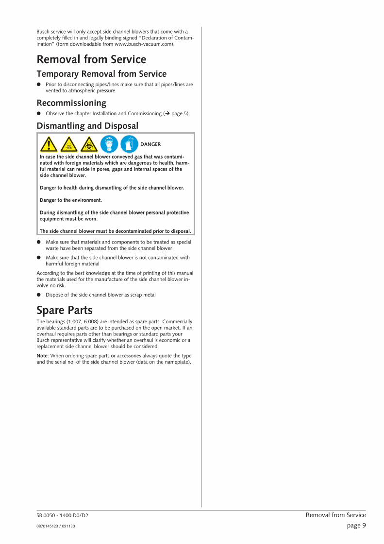
Dismantling and Disposal
DANGER_age32
In case the side channel blower conveyed gas that was contami-nated with foreign materials which are dangerous to health, harm-ful material can reside in pores, gaps and internal spaces of theside channel blower.
Danger to health during dismantling of the side channel blower.
Danger to the environment.
During dismantling of the side channel blower personal protectiveequipment must be worn.
The side channel blower must be decontaminated prior to disposal.
● Make sure that materials and components to be treated as specialwaste have been separated from the side channel blower
● Make sure that the side channel blower is not contaminated withharmful foreign material
According to the best knowledge at the time of printing of this manualthe materials used for the manufacture of the side channel blower in-volve no risk.
● Dispose of the side channel blower as scrap metal
Spare PartsThe bearings (1.007, 6.008) are intended as spare parts. Commerciallyavailable standard parts are to be purchased on the open market. If anoverhaul requires parts other than bearings or standard parts yourBusch representative will clarify whether an overhaul is economic or areplacement side channel blower should be considered.
Note: When ordering spare parts or accessories always quote the typeand the serial no. of the side channel blower (data on the nameplate).
SB 0050 - 1400 D0/D2 Removal from Service
0870145123 / 091130 page 9
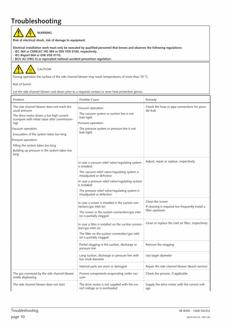
Troubleshooting
WARNING_ab
Risk of electrical shock, risk of damage to equipment.
Electrical installation work must only be executed by qualified personnel that knows and observes the following regulations:- IEC 364 or CENELEC HD 384 or DIN VDE 0100, respectively,- IEC-Report 664 or DIN VDE 0110,- BGV A2 (VBG 4) or equivalent national accident prevention regulation.
CAUTION_ac
During operation the surface of the side channel blower may reach temperatures of more than 70 °C.
Risk of burns!
Let the side channel blower cool down prior to a required contact or wear heat protection gloves.
Problem Possible Cause Remedy
The side channel blower does not reach theusual pressure
The drive motor draws a too high current(compare with initial value after commission-ing)
Vacuum operation:
Evacuation of the system takes too long
Pressure operation:
Filling the system takes too long
Building up pressure in the system takes toolong
Vacuum operation:
The vacuum system or suction line is notleak-tight
Pressure operation:
The pressure system or pressure line is notleak-tight
Check the hose or pipe connections for possi-ble leak
In case a vacuum relief valve/regulating systemis installed:
The vacuum relief valve/regulating system ismisadjusted or defective
In case a pressure relief valve/regulating systemis installed:
The pressure relief valve/regulating system ismisadjusted or defective
Adjust, repair or replace, respectively
In case a screen is installed in the suction con-nection/gas inlet (e):
The screen in the suction connection/gas inlet(e) is partially clogged
Clean the screen
If cleaning is required too frequently install afilter upstream
In case a filter is installed on the suction connec-tion/gas inlet (e):
The filter on the suction connection/gas inlet(e) is partially clogged
Clean or replace the inlet air filter, respectively
Partial clogging in the suction, discharge orpressure line
Remove the clogging
Long suction, discharge or pressure line withtoo small diameter
Use larger diameter
Internal parts are worn or damaged Repair the side channel blower (Busch service)
The gas conveyed by the side channel blowersmells displeasing
Process components evaporating under vac-uum
Check the process, if applicable
The side channel blower does not start The drive motor is not supplied with the cor-rect voltage or is overloaded
Supply the drive motor with the correct volt-age
Troubleshooting SB 0050 - 1400 D0/D2
page 10 0870145123 / 091130

The drive motor starter overload protection istoo small or trip level is too low
Compare the trip level of the drive motorstarter overload protection with the data onthe nameplate, correct if necessary
In case of high ambient temperature: set thetrip level of the drive motor starter overloadprotection 5 percent above the nominal drivemotor current
One of the fuses has blown Check the fuses
Version with alternating current motor:
The drive motor capacitor is defective
Repair the drive (Busch service)
The connection cable is too small or too longcausing a voltage drop at the side channelblower
Use sufficiently dimensioned cable
The side channel blower or the drive motor isblocked
Make sure the drive motor is disconnectedfrom the power supply
Remove the fan cover
Try to turn the drive motor with the sidechannel blower by hand
If the side channel blower is blocked:
Repair the side channel blower (Busch service)
The drive motor is defective Replace the drive motor (Busch service)
The side channel blower is blocked Solid foreign matter has entered the sidechannel blower
Repair the side channel blower (Busch service)
Make sure the suction line is equipped with ascreen
If necessary additionally provide a filter
Corrosion in the side channel blower from re-maining condensate
Repair the side channel blower (Busch service)
Check the process
Version with three-phase motor:
The side channel blower was run in the wrongdirection
Repair the side channel blower (Busch service)
When connecting the side channel blowermake sure the side channel blower will run inthe correct direction (� page 6: Installation)
The side channel blower starts, but labours orruns noisily or rattles
The drive motor draws a too high current(compare with initial value after commission-ing)
Loose connection(s) in the drive motor termi-nal box
Version with three-phase-motor:
Not all drive motor coils are properly con-nected
The drive motor operates on two phases only
Check the proper connection of the wiresagainst the connection diagram
Tighten or replace loose connections
Version with three-phase motor:
The side channel blower runs in the wrong di-rection
Verification and rectification� page 5: Instal-lation and Commissioning
Foreign objects in the side channel blower
Stuck bearings
Repair the side channel blower (Busch service)
The side channel blower runs very noisily Defective bearings Repair the side channel blower (Busch service)
The side channel blower runs very hot Insufficient air ventilation Make sure that the cooling of the side channelblower is not impeded by dust/dirt
Clean the fan cowling, the fan wheel, the ven-tilation grille and the cooling fins
Install the side channel blower in a narrowspace only if sufficient ventilation is ensured
Ambient temperature too high Observe the permitted ambient temperatures
Temperature of the inlet gas too high Observe the permitted temperatures for theinlet gas
SB 0050 - 1400 D0/D2 Troubleshooting
0870145123 / 091130 page 11

Insufficient gas transfer Vacuum operation:
Provide a vacuum relief valve
Pressure operation:
Provide a pressure relief valve
Mains frequency or voltage outside tolerancerange
Provide a more stable power supply
In case a vacuum relief valve/regulating systemis installed:
The vacuum relief valve/regulating system ismisadjusted or defective
In case a pressure relief valve/regulating systemis installed:
The pressure relief valve/regulating system ismisadjusted or defective
Adjust, repair or replace, respectively
Partial clogging of filters or screens
Partial clogging in the suction, discharge orpressure line
Remove the clogging
Long suction, discharge or pressure line withtoo small diameter
Use larger diameter
Troubleshooting SB 0050 - 1400 D0/D2
page 12 0870145123 / 091130

Exploded Views
SB 0050 - 1400 D0/D2 Exploded Views
0870145123 / 091130 page 13

Exploded Views SB 0050 - 1400 D0/D2
page 14 0870145123 / 091130

SB 0050 - 1400 D0/D2 Exploded Views
0870145123 / 091130 page 15

Exploded Views SB 0050 - 1400 D0/D2
page 16 0870145123 / 091130

SB 0050 - 1400 D0/D2 Exploded Views
0870145123 / 091130 page 17

Exploded Views SB 0050 - 1400 D0/D2
page 18 0870145123 / 091130

SB 0050 - 1400 D0/D2 EC-Declaration of Conformity
0870145123 / 091130 page 19
EC-Declaration of Conformity Note : This Declaration of Conformity and the CE-mark affixed to the nameplate are valid for the machine within the Busch scope of delivery. This Declaration of Conformity is issued under the sole responsibility of the manufacturer. When this machine is integrated into a superordinate machinery the manufacturer of the superordinate machinery (this can be the operating company, too) must conduct the conformity assessment process for the superordinate machine or plant, issue the Declaration of Conformity for it and affix the CE-mark.
We
Busch Produktions GmbH Schauinslandstr. 1 79689 Maulburg Germany
Declare that the vacuum pumps SB 0050 - 1400 D0/D2
with a serial number from D1601… to D1752…
has (have) been manufactured in accordance with the European Directives:
• ‘Machinery’ 2006/42/EC
• ‘Electromagnetic Compatibility’ 2014/30/EU
• ‘RoHS’ 2011/65/EU, restriction of the use of certain hazardous substances in electrical and electronic equipment
and following the standards.
Standard Title of the Standard
EN ISO 12100: 2010 Safety of machinery –General principles for design –Risk assessment and risk reduction
EN ISO 13857: 2008 Safety of machinery - Safety distances to prevent hazard zones being reached by the upper and lower limbs
EN 1012-1: 2010 EN 1012-2: 1996 + A1: 2009
Compressors and vacuum pumps - Safety requirements - Part 1 and Part 2
EN ISO 2151: 2008 Acoustics - Noise test code for compressors and vacuum pumps - Engineering method (grade 2)
EN 60204-1: 2006 Safety of machinery - Electrical equipment of machines - Part 1: General requirements
EN 61000-6-2: 2005 Electromagnetic compatibility (EMC) - Generic immunity standards. Immunity for industrial environments
EN 61000-6-4: 2007 + A1: 2011 Electromagnetic compatibility (EMC) - Generic immunity standards. Emission standard for industrial environments
EN ISO 13849-1:2015 (1) Safety of machinery - Safety-related parts of control systems - Part 1: General principles for design
Manufacturer
Dr.-Ing. Karl Busch General Director
Person authorized to compile the technical file
Andrej Riwe Technical writer
Maulburg, 04.04.2016

Busch – All over the World in Industry www.busch-vacuum.comAustraliaBusch Australia Pty. Ltd.30 Lakeside DriveBroadmeadows, Vic. 3047Tel: (03) 93 55 06 00Fax: (03) 93 55 06 99
AustriaBusch Austria GmbHIndustriepark Nord2100 KorneuburgTel: 02262 / 756 65-0Fax: 02262 / 756 65-20
BelgiumBusch N.V./Busch SAKruinstraat 79160 LokerenTel: (0)9 / 348 47 22Fax: (0)9 / 348 65 35
BrazilBusch do Brasil Ltda.Rod. Edgard Máximo Zambotto, Km 6413240-000 Jarinu-SPTel: (55) 11-4016 1400/5277Fax: (55) 11-4016 5399
CanadaBusch Vacuum Technics Inc.1740, Boulevard Lionel BertrandBoisbriand (Montréal)Québec J7H 1N7Tel: 450 435 6899Fax: 450 430 5132
ChileBusch Chile S. A.Calle El Roble N° 375-GLampa - SantiagoTel: (56-2) 7387092Fax: (56-2) 7387092
ChinaBusch Vacuum (Shanghai) Co., LtdNo.5, Lane 195 Xipu RoadSongjiang Industrial Estate East New ZoneShanghai 201611 PRCTel: +86 (0)21 67600800Fax: +86 (0)21 67600700
Czech RepublicBusch Vakuum s.r.o.Pra�ákova 10619 00 Horní HeršpiceBrnoTel: +420 543 42 48 55Fax: +420 543 42 48 56
DenmarkBusch Vakuumteknik A/SParallelvej 118680 RyTel: +45 87 88 07 77Fax: +45 87 88 07 88
FinlandBusch Vakuumteknik OySinikellontie 401300 VANTAATel: 09 774 60 60Fax: 09 774 60 666
FranceBusch France S.A.Parc Technologiquede Bois Chaland CE 292291029 Evry CedexTel: 01 69 89 89 89Fax: 01 60 86 16 74
GermanyDr.-Ing. K. Busch GmbHSchauinslandstr. 179689 MaulburgTel: (0 76 22) 6 81-0Fax: (0 76 22) 6 81-194e-mail: [email protected]
Dr.-Ing. K. Busch GmbHNiederlassung NordErnst-Abbe-Str. 1-325451 QuickbornTel: (0 41 06) 7 99 67-0Fax: (0 41 06) 7 99 67-77
Dr.-Ing. K. Busch GmbHNiederlassung WestNordring 3564807 DieburgTel: (0 60 71) 92 82-0Fax: (0 60 71) 14 71
Dr.-Ing. K. Busch GmbHAußenstelle NeuenradeBreslauer Str. 3658809 NeuenradeTel: (0 23 92) 50 29 92Fax: (0 23 92) 50 72 11
Dr.-Ing. K. Busch GmbHNiederlassung Süd-OstGewerbestraße 390579 LangenzennTel: (09 01) 90 25-0Fax: (09 01) 90 25-25
Dr.-Ing. K. Busch GmbHAußenstelle Zella-MehlisAm Rain 1198544 Zella-MehlisTel: (0 36 82) 46 92 71Fax: (0 36 82) 46 92 73
Dr.-Ing. K. Busch GmbHAußenstelle Meitingen-OstendorfGrüntenweg 886405 Meitingen-OstendorfTel: (0 82 71) 426-341Fax: (0 82 71) 426-342
IndiaBusch Vacuum India Pvt Ltd.Plot No. 110, Sector 7PCNTDA, BhosariPune 411026, MaharashtraTel: (0)206410 2886Fax: (0)202711 2838
IrelandBusch Ireland Ltd.A10-11 Howth Junction Business CentreKilbarrack, Dublin 5Tel: 00353 1 832 1466Fax: 00353 1 832 1470
IsraelBusch Israel Ltd.1 Mevo Sivan StreetQiryat Gat 82022, IsraelTel: +972 (0)8 6810485Fax +972 (0)8 6810486
ItalyBusch Italia S.r.l.Via Ettore Majorana, 1620054 Nova MilaneseTel: 0362 370 91Fax: 0362 370 999
JapanNippon Busch K.K.1-23-33, MegumigaokaHiratsuka City, KanagawaJapan 259-1220Tel: 0463-50-4000Fax: 0463-50-4004
KoreaBusch Korea Ltd.392-1 Yangji-Ri, Yangji-Myun,Yongin-si, Kyunggi-DoTel: 031) 321-8114Fax: 031) 321 4330
MalaysiaBusch (Malaysia) Sdn Bhd.6 Jalan Taboh 33/22Shah Alam Technology ParkSection 3340400 Shah AlamSelangor D. E.Tel: 03 5122 2128Fax 03 5122 2108
MexicoBusch Vacuum Mexico S de RL de CVTlaquepaque 4865, Los AltosMonterrey, Nuevo LeonMexico 64370Tel: (81) 8311-1385Fax: (81) 8311-1386
NetherlandsBusch B.V.Pompmolenlaan 23447 GK WoerdenPostbus 20913440 DB WoerdenTel: (0)348 - 462300Fax: (0)348 - 422939
New ZealandBusch New Zealand Ltd.Unit D, 41 Arrenway DriveAlbany 0632AucklandTel: 09 414 7782Fax: 09 414 7783
NorwayBusch Vakuumteknikk ASHestehagen 21440 DrøbakTel: 64 98 98 50Fax: 64 93 66 21
PolandBusch Polska Sp. z o.o.Ul. Chopina 2787800 W�oc�awekTel: (054) 2315400Fax: (054) 2327076
PortugalBusch lbérica S.A., Sucursal em PortugalZona Industrial Raso de Travassô, Fracção B, Armazém 23750-753 AguedaAveiro, PortugalTel: +351 234 648 070Fax: +351 234 648 068
SingaporeBusch Vacuum Singapore Pte Ltd20 Shaw Road#01-03 Ching Shine BuildingSingapore 36 79 56Tel: (65) 6488 0866Fax: (65) 6288 0877
SpainBusch Ibérica S.A.C/ Jaume Ferran, 6-8Pol. Ind. Coll de la Manya08403 GranollersTel: +34 93 861 61 60Fax: +34 93 840 91 56
SwedenBusch Vakuumteknik ABBråta Industriområde435 33 MölnlyckeTel: 031 - 338 00 80Fax: 031 - 338 00 89
SwitzerlandBusch AGWaldweg 224312 MagdenTel: 061 / 845 90 90Fax: 061 / 845 90 99
TaiwanBusch Taiwan Corporation1F. No. 69, Sec. 3, Beishen Rd.Shenkeng Township,Taipei Country,Taiwan (222), R.O.CTel: (02) 2662 0775Fax: (02) 2662 0796
ThailandBusch Vacuum (Thailand) Co., Ltd.888/30 Moo19, Soi Yingcharoen, Bangplee-Tamru Rd.,Bangpleeyai, Bangplee, Samutprakarn 10540 ThailandTel: (66) 2-382-5428Fax: (66) 2-382-5429
TurkeyVAKUTEKEmlak Kredi Ishani No: 17981130 Üsküdar-IstanbulTel: (216) 310 0573Fax: (216) 343 5126
United KingdomBusch (UK) LtdHortonwood 30-35Telford Shropshire TF1 7YBTel: 01952 677 432Fax: 01952 677 423
USABusch, Inc.516-B Viking DriveVirginia Beach, VA 23452Tel: (757) 463-7800Fax: (757) 463 7407
Semiconductor Vacuum Group Inc.Morgan Hill, CA 95037Tel: (408) 955 1900Fax: (408) 955 0229
Busch – All over the World in Industry
page 200870145123