installation and operating instructions - … · installation of electronic control modules...
TRANSCRIPT
Page 1 23/03/01
Ca 7s and BCa 7s 61-235 kW
INSTALLATION AND
OPERATING INSTRUCTIONS
Page 2 23/03/01
CONTENTS: Dimensions for Ca7s and BCa7s boilers. General specification Boiler room clearance requirements Boiler block assembly Pulling up the sections Boiler block assembly & connections Ca7s Jacket assembly Calorifier assembly BCa7s Jacket assembly Continued Electrical connection and Instrument control panel Continued Control module options Control module diagrams Installation of electronic control modules Terminal wiring diagram Schematic wiring diagram Important notes & burner connection information.
PAGE:
3 & 4 5 6 7 8 9
10
11
12
13
14
15
16
17
18
19
20
21
Page 3 23/03/01
General Specifications The STREBEL Camino 7s is a special boiler for oil or gas fired pressure jet burner. In the BICALOR construction a calorifier for the supply of hot water is built onto the boiler. CSH-S type calorifiers are manufactured from 1.4571 high tensile steel with an incorporated heating coil of galvanised copper ribbed pipe. Triple pass block of cast iron sections. The first pass is the combustion chamber. From there the flue gases pass between the rear section and the last intermediate section through the second pass to the front of the boiler. They are then diverted into the third pass and flow back to the rear through the flue spigot into the chimney. Flue baffles of cast iron can be introduced into the flue passes in order to influence the flue gas temperature depending on chimney conditions. The boiler can be used with an oil or gas burner. Brief description. • Corrosion resistant block of cast iron sections. • Triple pass boiler with optimised use of energy. • High efficiency. • Built-in instrument panel with multiple control
possibilities and retro-fit control options. • Easy erection and cleaning. • Modern design. Operating conditions Boiler: Maximum operating temperature up to 110ºC Maximum operating temperature up to 120ºC depending on technical safety of the equipment. Maximum operating pressure 4.0 bar Maximum test pressure 5.2 bar
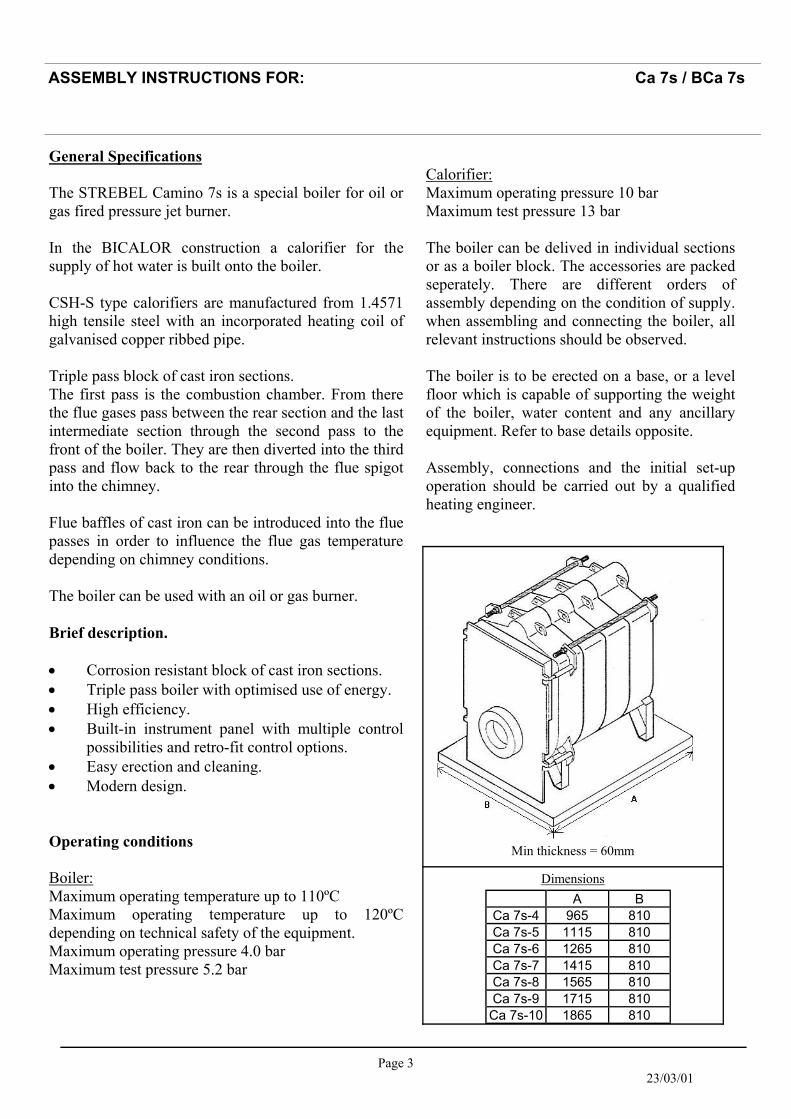
Min thickness = 60mm
A B Ca 7s-4 965 810 Ca 7s-5 1115 810 Ca 7s-6 1265 810 Ca 7s-7 1415 810 Ca 7s-8 1565 810 Ca 7s-9 1715 810 Ca 7s-10 1865 810
Dimensions
ASSEMBLY INSTRUCTIONS FOR: Ca 7s / BCa 7s
Calorifier: Maximum operating pressure 10 bar Maximum test pressure 13 bar The boiler can be delived in individual sections or as a boiler block. The accessories are packed seperately. There are different orders of assembly depending on the condition of supply.when assembling and connecting the boiler, all relevant instructions should be observed. The boiler is to be erected on a base, or a level floor which is capable of supporting the weight of the boiler, water content and any ancillary equipment. Refer to base details opposite. Assembly, connections and the initial set-up operation should be carried out by a qualified heating engineer.
Page 4 23/03/01
ASSEMBLY INSTRUCTIONS FOR: Ca 7s / BCa 7s
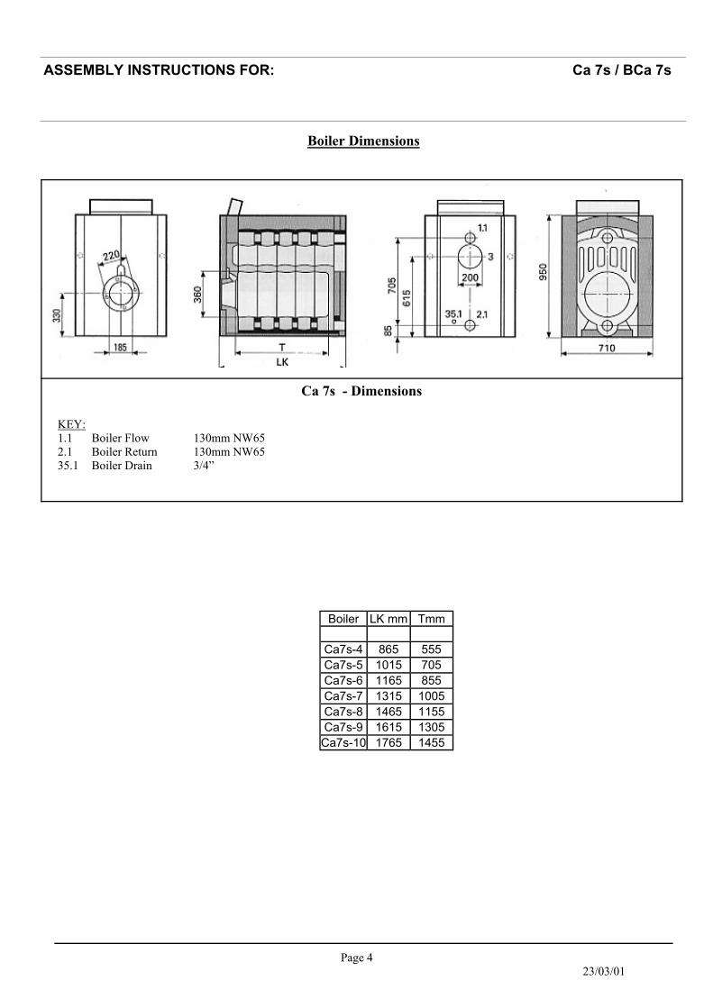
Boiler Dimensions
Ca 7s - Dimensions
Boiler LK mm Tmm
Ca7s-4 865 555 Ca7s-5 1015 705 Ca7s-6 1165 855 Ca7s-7 1315 1005 Ca7s-8 1465 1155 Ca7s-9 1615 1305 Ca7s-10 1765 1455
KEY: 1.1 Boiler Flow 130mm NW65 2.1 Boiler Return 130mm NW65 35.1 Boiler Drain 3/4”
Page 5 23/03/01
ASSEMBLY INSTRUCTIONS FOR: Ca 7s / BCa 7s
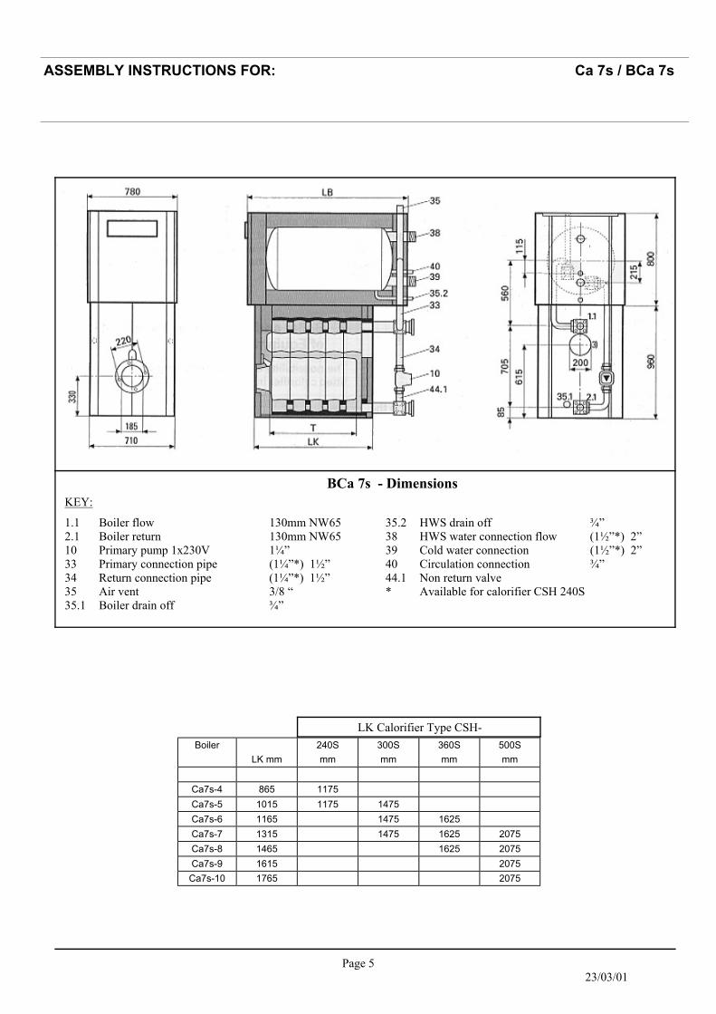
BCa 7s - Dimensions
LK Calorifier Type CSH- Boiler 240S 300S 360S 500S
LK mm mm mm mm mm
Ca7s-4 865 1175 Ca7s-5 1015 1175 1475 Ca7s-6 1165 1475 1625 Ca7s-7 1315 1475 1625 2075 Ca7s-8 1465 1625 2075 Ca7s-9 1615 2075 Ca7s-10 1765 2075
1.1 Boiler flow 130mm NW65 2.1 Boiler return 130mm NW65 10 Primary pump 1x230V 1¼” 33 Primary connection pipe (1¼”*) 1½” 34 Return connection pipe (1¼”*) 1½” 35 Air vent 3/8 “ 35.1 Boiler drain off ¾”
35.2 HWS drain off ¾” 38 HWS water connection flow (1½”*) 2” 39 Cold water connection (1½”*) 2” 40 Circulation connection ¾” 44.1 Non return valve * Available for calorifier CSH 240S
KEY:

Page 6 23/03/01
Diagram showing clearances required in boiler room. The clearance details shown above are required for access to the boilers for maintenance purposes. Slight variations may apply, depending on the specific installation.
ASSEMBLY INSTRUCTIONS FOR: Ca 7s / BCa 7s

Page 7 23/03/01
Once assembled, the boiler block is to be secured with the tie bars (2 at the top, and 2 at the bottom). Prior to screwing nuts up ensure the two disc springs (5)&(6) are slotted on with concave sides facing each other. The nuts can now be tightened until the disc springs flatten. The burner door hinges should now be fitted on the left or right hand side of the front section depending on requirements. Ensure the eyelet screws (door hinge) are at the same depth and when the door is closed it should press flat with the front section.
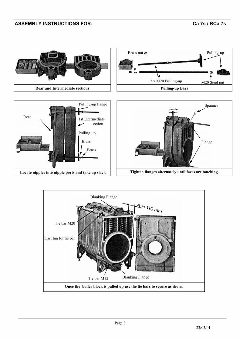
Boiler Block Assembly The boiler block is assembled by ‘pulling-up’ each section in turn starting from the rear section (1). All other sections (2)(3)(4) are mounted individually using the pulling-up tools. One face of the adjoining sections must have a length of mastic sealing strand placed into the mastic groove. Each of the boiler nipples must be inspected to ensure there is no damage apparent. The nipples and nipple ports should then be kept free from dirt and checked at each stage of assembly. Particles of dirt which are not removed lead to leakage. The accompanying nipple jointing oil serves as a lubricant as well as a waterproof seal and must be used. Boiler nipples and nipple ports must align exactly at all stages of assembly. An inclined, retracted nipple leads to leakage. The clearance between the sections throughout the pulling-up stages should always be even. If the clearance is uneven, a flat chisel should be inserted into the narrower point and the sections pulled up until the clearance is even again.
Diagram showing nipple & boring
ASSEMBLY INSTRUCTIONS FOR: Ca 7s / BCa 7s
Page 8 23/03/01
Rear and Intermediate sections Pulling-up Bars
Pulling-up Brass nut &
2 x M20 Pulling-up M20 Steel nut
Locate nipples into nipple ports and take up slack
Pulling-up flange
1st Intermediate section
Pulling-up
Brass
Brass
Rear
Spanner
Flange
Tighten flanges alternately until faces are touching.
Blanking Flange
Blanking Flange
Tie bar M12
Tie bar M20
Cast lug for tie bar
Once the boiler block is pulled up use the tie bars to secure as shown
ASSEMBLY INSTRUCTIONS FOR: Ca 7s / BCa 7s
Page 9 23/03/01
Cold water pressure test: The assembled boiler is to be subjected to a cold water pressure test of 1.5 times the operating pressure. The maximum test pressure of the boiler is 5.2 bar. In addition, at the time of testing for water pressure, no pressure control fittings or safety fittings may be assembled which cannot be separated from the water area of the boiler. Only fill, slowly from the bottom via the filling and draining cock. Ventilate during the filling procedure from time to time, until the water emerges. If a nipple connection is leaking then drain off the water via the filling and draining cock. Separate by driving flat wedges around the perimeter of the join between sections. New nipples MUST be used for re-assembly. Assemble and repeat test.
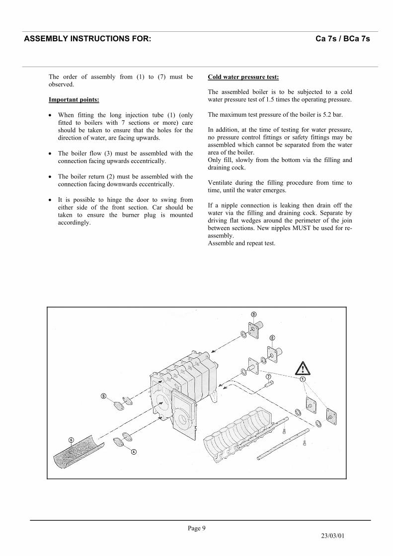
The order of assembly from (1) to (7) must be observed. Important points: • When fitting the long injection tube (1) (only
fitted to boilers with 7 sections or more) care should be taken to ensure that the holes for the direction of water, are facing upwards.
• The boiler flow (3) must be assembled with the
connection facing upwards eccentrically. • The boiler return (2) must be assembled with the
connection facing downwards eccentrically. • It is possible to hinge the door to swing from
either side of the front section. Car should be taken to ensure the burner plug is mounted accordingly.
ASSEMBLY INSTRUCTIONS FOR: Ca 7s / BCa 7s
Page 10 23/03/01
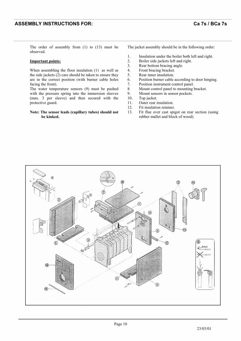
The order of assembly from (1) to (13) must be observed. Important points: When assembling the floor insulation (1) as well as the side jackets (2) care should be taken to ensure they are in the correct position (with burner cable holes facing the front). The water temperature sensors (9) must be pushed with the pressure spring into the immersion sleeves (max. 3 per sleeve) and then secured with the protective guard. Note: The sensor leads (capillary tubes) should not be kinked.
The jacket assembly should be in the following order: 1. Insulation under the boiler both left and right. 2. Boiler side jackets left and right. 3. Rear bottom bracing angle. 4. Front bracing bracket. 5. Rear inner insulation. 6. Position burner cable according to door hinging. 7. Position instrument control panel. 8. Mount control panel to mounting bracket. 9. Mount sensors in sensor pockets. 10. Top jacket. 11. Outer rear insulation. 12. Fit insulation retainer. 13. Fit flue over cast spigot on rear section (using
rubber mallet and block of wood).
ASSEMBLY INSTRUCTIONS FOR: Ca 7s / BCa 7s
Page 11 23/03/01
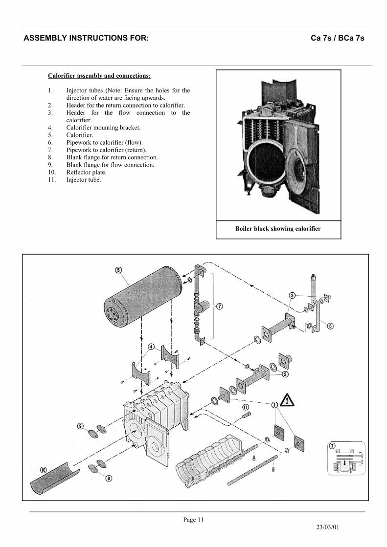
Calorifier assembly and connections: 1. Injector tubes (Note: Ensure the holes for the
direction of water are facing upwards. 2. Header for the return connection to calorifier. 3. Header for the flow connection to the
calorifier. 4. Calorifier mounting bracket. 5. Calorifier. 6. Pipework to calorifier (flow). 7. Pipework to calorifier (return). 8. Blank flange for return connection. 9. Blank flange for flow connection. 10. Reflector plate. 11. Injector tube.
Boiler block showing calorifier
ASSEMBLY INSTRUCTIONS FOR: Ca 7s / BCa 7s
Page 12 23/03/01
ASSEMBLY INSTRUCTIONS FOR: Ca 7s / BCa 7s
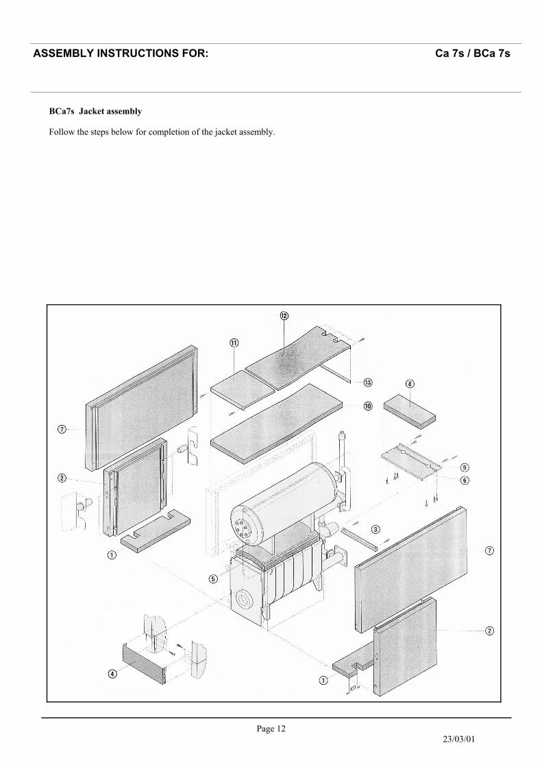
BCa7s Jacket assembly Follow the steps below for completion of the jacket assembly.
Page 13 23/03/01
ASSEMBLY INSTRUCTIONS FOR: Ca 7s / BCa 7s
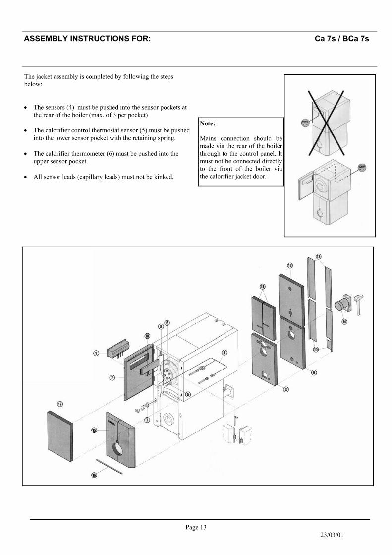
The jacket assembly is completed by following the steps below: • The sensors (4) must be pushed into the sensor pockets at
the rear of the boiler (max. of 3 per pocket) • The calorifier control thermostat sensor (5) must be pushed
into the lower sensor pocket with the retaining spring. • The calorifier thermometer (6) must be pushed into the
upper sensor pocket. • All sensor leads (capillary leads) must not be kinked.
Note: Mains connection should be made via the rear of the boiler through to the control panel. It must not be connected directly to the front of the boiler via the calorifier jacket door.
Page 14 23/03/01
ASSEMBLY INSTRUCTIONS FOR: Ca 7s / BCa 7s
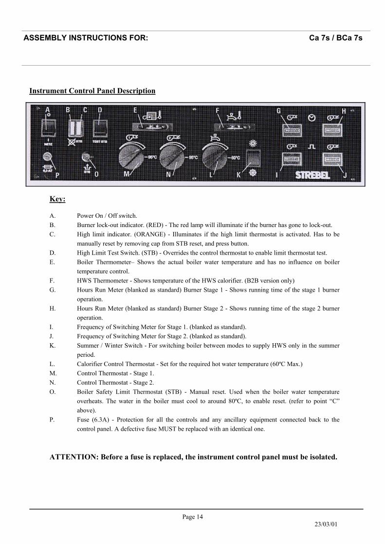
Instrument Control Panel Description
Key: A. Power On / Off switch. B. Burner lock-out indicator. (RED) - The red lamp will illuminate if the burner has gone to lock-out. C. High limit indicator. (ORANGE) - Illuminates if the high limit thermostat is activated. Has to be
manually reset by removing cap from STB reset, and press button. D. High Limit Test Switch. (STB) - Overrides the control thermostat to enable limit thermostat test. E. Boiler Thermometer– Shows the actual boiler water temperature and has no influence on boiler
temperature control. F. HWS Thermometer - Shows temperature of the HWS calorifier. (B2B version only) G. Hours Run Meter (blanked as standard) Burner Stage 1 - Shows running time of the stage 1 burner
operation. H. Hours Run Meter (blanked as standard) Burner Stage 2 - Shows running time of the stage 2 burner
operation. I. Frequency of Switching Meter for Stage 1. (blanked as standard). J. Frequency of Switching Meter for Stage 2. (blanked as standard). K. Summer / Winter Switch - For switching boiler between modes to supply HWS only in the summer
period. L. Calorifier Control Thermostat - Set for the required hot water temperature (60ºC Max.) M. Control Thermostat - Stage 1. N. Control Thermostat - Stage 2. O. Boiler Safety Limit Thermostat (STB) - Manual reset. Used when the boiler water temperature
overheats. The water in the boiler must cool to around 80ºC, to enable reset. (refer to point “C” above).
P. Fuse (6.3A) - Protection for all the controls and any ancillary equipment connected back to the control panel. A defective fuse MUST be replaced with an identical one.
ATTENTION: Before a fuse is replaced, the instrument control panel must be isolated.
Page 15 23/03/01
ASSEMBLY INSTRUCTIONS FOR: Ca 7s / BCa 7s
B2B Panel
K2B Panel
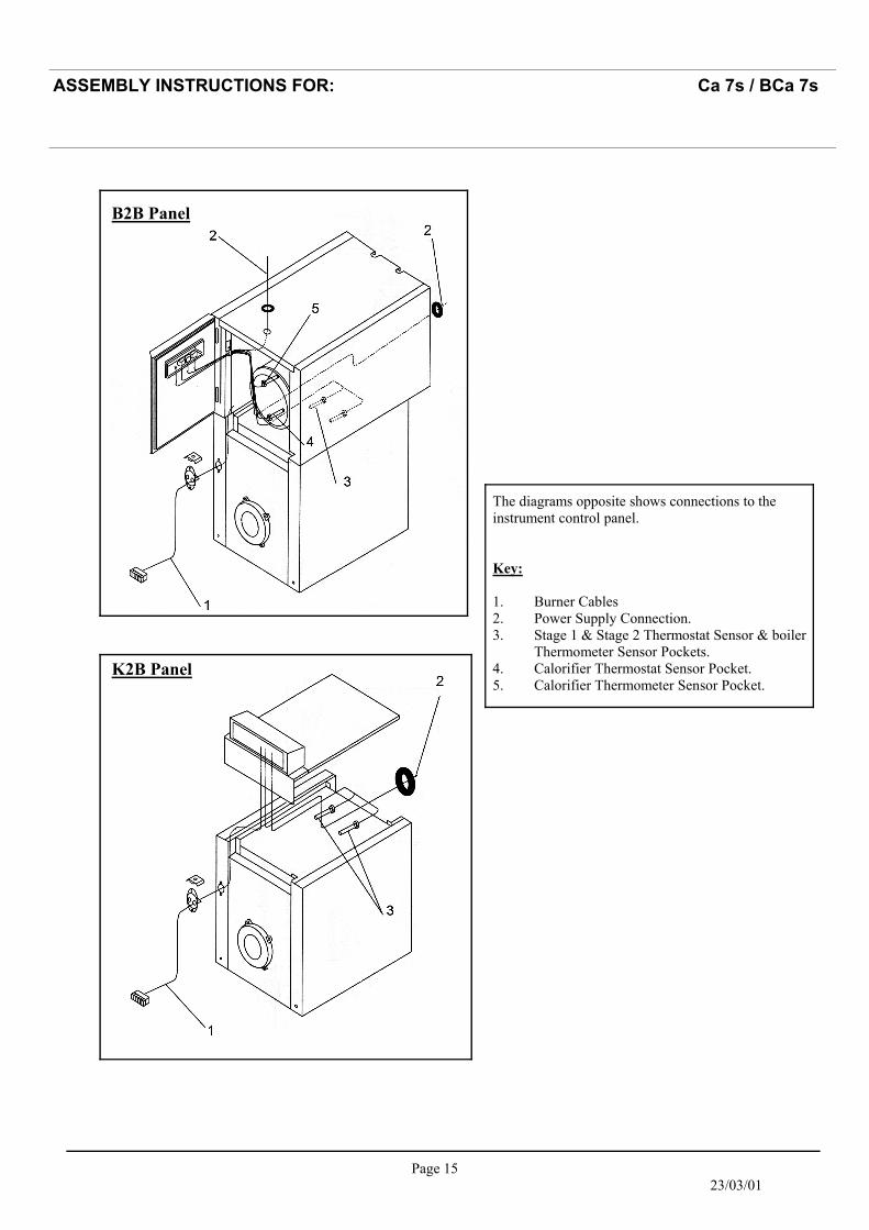
The diagrams opposite shows connections to the instrument control panel. Key: 1. Burner Cables 2. Power Supply Connection. 3. Stage 1 & Stage 2 Thermostat Sensor & boiler
Thermometer Sensor Pockets. 4. Calorifier Thermostat Sensor Pocket. 5. Calorifier Thermometer Sensor Pocket.
Page 16 23/03/01
ASSEMBLY INSTRUCTIONS FOR: Ca 7s / BCa 7s
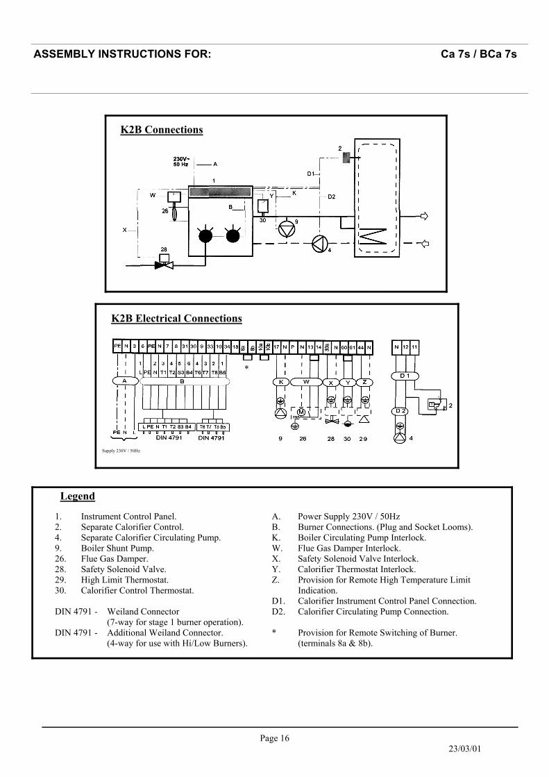
K2B Connections
Supply 230V / 50Hz
K2B Electrical Connections
*
Legend
1. Instrument Control Panel. 2. Separate Calorifier Control. 4. Separate Calorifier Circulating Pump. 9. Boiler Shunt Pump. 26. Flue Gas Damper. 28. Safety Solenoid Valve. 29. High Limit Thermostat. 30. Calorifier Control Thermostat. DIN 4791 - Weiland Connector (7-way for stage 1 burner operation). DIN 4791 - Additional Weiland Connector. (4-way for use with Hi/Low Burners).
A. Power Supply 230V / 50Hz B. Burner Connections. (Plug and Socket Looms). K. Boiler Circulating Pump Interlock. W. Flue Gas Damper Interlock. X. Safety Solenoid Valve Interlock. Y. Calorifier Thermostat Interlock. Z. Provision for Remote High Temperature Limit Indication. D1. Calorifier Instrument Control Panel Connection. D2. Calorifier Circulating Pump Connection. * Provision for Remote Switching of Burner. (terminals 8a & 8b).
Page 17 23/03/01
ASSEMBLY INSTRUCTIONS FOR: Ca 7s / BCa 7s
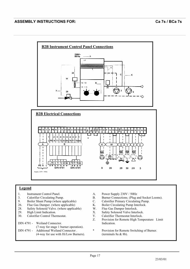
B2B Instrument Control Panel Connections
B2B Electrical Connections
Supply 230V / 50Hz
*
Legend 1. Instrument Control Panel. 3. Calorifier Circulating Pump. 9. Boiler Shunt Pump (where applicable) 26. Flue Gas Damper. (where applicable) 28. Safety Solenoid Valve. (where applicable) 29. High Limit Indication. 30. Calorifier Control Thermostat. DIN 4791 - Weiland Connector. (7-way for stage 1 burner operation). DIN 4791 - Additional Weiland Connector . (4-way for use with Hi/Low Burners).
A. Power Supply 230V / 50Hz B. Burner Connections. (Plug and Socket Looms). C. Calorifier Primary Circulating Pump. K. Boiler Circulating Pump Interlock. W. Flue Gas Damper Interlock. X. Safety Solenoid Valve Interlock. Y. Calorifier Thermostat Interlock. Z. Provision for Remote High Temperature Limit Indication. * Provision for Remote Switching of Burner. (terminals 8a & 8b).

Page 18 23/03/01
ASSEMBLY INSTRUCTIONS FOR: Ca 7s / BCa 7s
Leg
end:
1.
1
Pow
er S
witc
h O
N/O
FF.
1.2
S
umm
er /
Win
ter S
witc
h.
1.3
H
igh
Lim
it ST
B T
est
S
witc
h.
1.4
B
oile
r Lim
it Th
erm
osta
t. 1.
5
Boi
ler T
herm
osta
t Sta
ge 1
. 1.
6
Boi
ler T
herm
osta
t Sta
ge 2
. 1.
8
Hou
rs R
un M
eter
Sta
ge 1
. 1.
8a
Fre
quen
cy o
f Sw
itchi
ng
S
tage
1 (o
ptio
nal).
1.
9
Hou
rs R
un M
eter
Sta
ge 2
. 1.
9a
Fre
quen
cy o
f Sw
itchi
ng
S
tage
2 (o
ptio
nal).
1.
14
Boi
ler L
imit
Ther
mos
tat
(for
ope
ratio
n at
110
ºC (
optio
nal
extra
). 1.
20
Bur
ner L
ock-
out L
amp
1.21
H
igh
Lim
it La
mp.
1.
23
Fus
e 6.
3A.
K2B
Inst
rum
ent C
ontr
ol P
anel
- In
tern
al W
irin
g D
iagr
am
Page 19 23/03/01
ASSEMBLY INSTRUCTIONS FOR: Ca 7s / BCa 7s
Leg
end:
1.
1
Pow
er S
witc
h.
1.2
S
umm
er /
Win
ter S
witc
h.
1.3
H
igh
Lim
it ST
B T
est
S
witc
h.
1.4
B
oile
r Lim
it Th
erm
osta
t. 1.
5
Boi
ler T
herm
osta
t Sta
ge 1
. 1.
6
Boi
ler T
herm
osta
t Sta
ge 2
. 1.
7
Cal
orifi
er T
herm
osta
t. 1.
8
Hou
rs R
un M
eter
Sta
ge 1
. 1.
8a
1.
9
Hou
rs R
un M
eter
Sta
ge 2
. 1.
9a
1.14
1.20
B
urne
r Loc
k-ou
t Lam
p 1.
21
Hig
h Li
mit
Lam
p.
1.23
F
use
6.3A
.
Leg
end:
1.
1
Pow
er S
witc
h O
N/O
FF.
1.2
S
umm
er /
Win
ter S
witc
h.
1.3
H
igh
Lim
it ST
B T
est
S
witc
h.
1.4
B
oile
r Lim
it Th
erm
osta
t. 1.
5
Boi
ler T
herm
osta
t Sta
ge 1
. 1.
6
Boi
ler T
herm
osta
t Sta
ge 2
. 1.
7
Cal
orifi
er T
herm
osta
t. 1.
8
Hou
rs R
un M
eter
Sta
ge 1
. 1.
8a
Fre
quen
cy o
f Sw
itchi
ng
S
tage
1 (o
ptio
nal).
1.
9
Hou
rs R
un M
eter
Sta
ge 2
. 1.
9a
Fre
quen
cy o
f Sw
itchi
ng
S
tage
2 (o
ptio
nal).
1.
14
Boi
ler L
imit
Ther
mos
tat
(for
ope
ratio
n at
110
ºC (
optio
nal
extra
). 1.
20
Bur
ner L
ock-
out L
amp
1.21
H
igh
Lim
it La
mp.
1.
23
Fus
e 6.
3A.
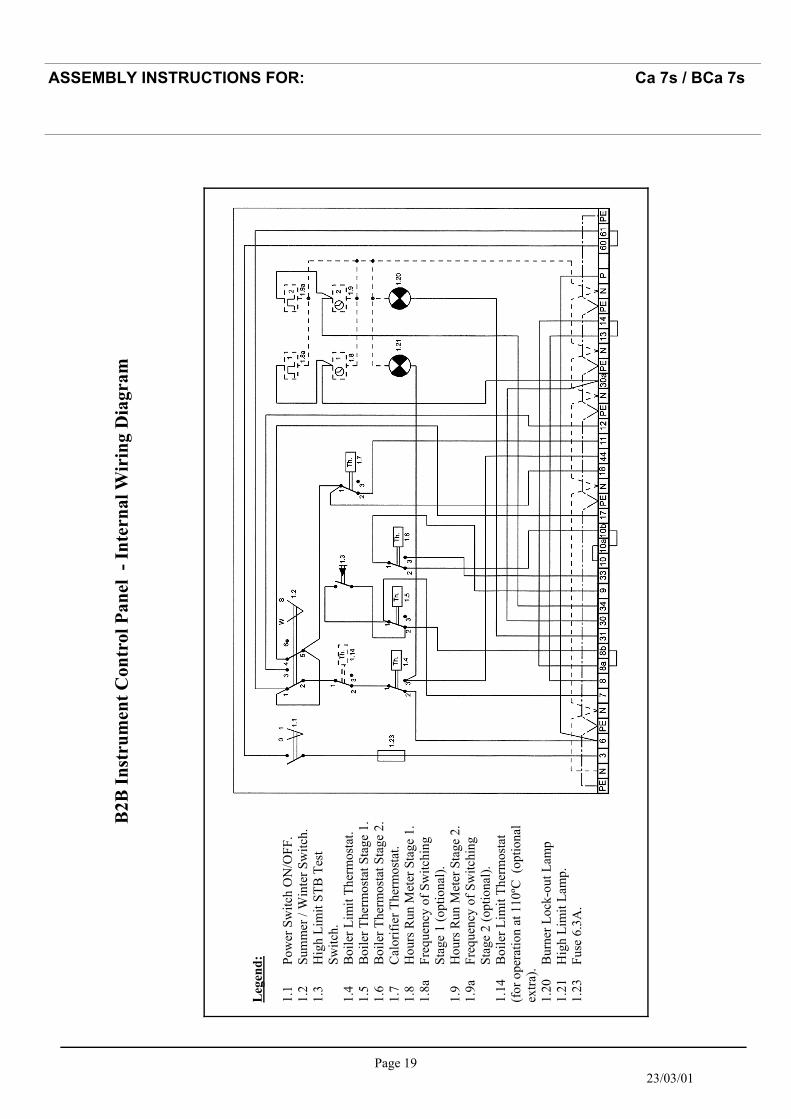
B2B
Inst
rum
ent C
ontr
ol P
anel
- In
tern
al W
irin
g D
iagr
am
Page 20 23/03/01
ASSEMBLY INSTRUCTIONS FOR: Ca 7s / BCa 7s
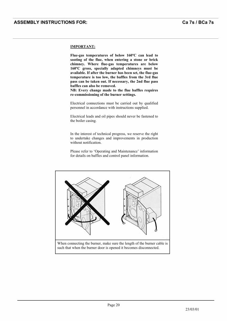
When connecting the burner, make sure the length of the burner cable is such that when the burner door is opened it becomes disconnected.
IMPORTANT: Flue-gas temperatures of below 160ºC can lead to sooting of the flue, when entering a stone or brick chimney. Where flue-gas temperatures are below 160ºC gross, specially adapted chimneys must be available. If after the burner has been set, the flue-gas temperature is too low, the baffles from the 3rd flue pass can be taken out. If necessary, the 2nd flue pass baffles can also be removed. NB: Every change made to the flue baffles requires re-commissioning of the burner settings. Electrical connections must be carried out by qualified personnel in accordance with instructions supplied. Electrical leads and oil pipes should never be fastened to the boiler casing. In the interest of technical progress, we reserve the right to undertake changes and improvements in production without notification. Please refer to ‘Operating and Maintenance’ information for details on baffles and control panel information.

Page 21 23/03/01
STREBEL LTD 1F Albany Park Industrial Estate Frimley Road, Camberley, Surrey, GU16 7PB Telephone: 01276 685422 Fax: 01276 685405 E-mail address: [email protected] Website: www.strebel.co.uk
THE COMPANY RESERVES THE RIGHT TO CHANGE SPECIFICATIONS AND DIMENSIONS WITHOUT NOTICE
ASSEMBLY INSTRUCTIONS FOR: Ca 7s / BCa 7s
E. & O.E