installation and operating instructions - precision · pdf filethis manual supplies...
TRANSCRIPT
1
Installation and Operating Instructions
TYPE ‘SP’ SPRAY
& ‘TR’ Tray DEAERATOR
2
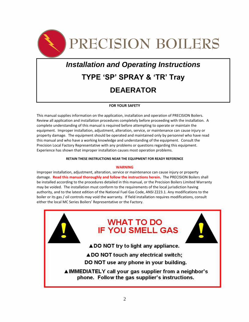
FOR YOUR SAFETY
This manual supplies information on the application, installation and operation of PRECISION Boilers. Review all application and installation procedures completely before proceeding with the installation. A complete understanding of this manual is required before attempting to operate or maintain the equipment. Improper installation, adjustment, alteration, service, or maintenance can cause injury or property damage. The equipment should be operated and maintained only by personnel who have read this manual and who have a working knowledge and understanding of the equipment. Consult the Precision Local Factory Representative with any problems or questions regarding this equipment. Experience has shown that improper installation causes most operation problems.
RETAIN THESE INSTRUCTIONS NEAR THE EQUIPMENT FOR READY REFERENCE
WARNING Improper installation, adjustment, alteration, service or maintenance can cause injury or property damage. Read this manual thoroughly and follow the instructions herein. The PRECISION Boilers shall be installed according to the procedures detailed in this manual, or the Precision Boilers Limited Warranty may be voided. The installation must conform to the requirements of the local jurisdiction having authority, and to the latest edition of the National Fuel Gas Code, ANSI Z223.1. Any modifications to the boiler or its gas / oil controls may void the warranty. If field installation requires modifications, consult either the local MC Series Boilers’ Representative or the Factory.
Installation and Operating Instructions
TYPE ‘SP’ SPRAY & ‘TR’ Tray
DEAERATOR

3
TABLE OF CONTENTS i Title page ............................................................... 1
ii Introduction ............................................................ 2
iii Index ...................................................................... 3
1.0 PRINCIPLES OF DEAERATION
1.1 Corrosion ........................................................... 4
1.2 Common Gases.................................................. 4
1.2.1 Oxygen ............................................................ 4
1.2.2 Carbon Dioxide ............................................... 4
2.0 PHYSICAL LAWS
2.1 Boyle’s Law ........................................................ 5
2.2 Dalton’s Law ...................................................... 5
2.3 Henry’s Law ....................................................... 5
2.4 Summary ........................................................... 5
3.0 MECHANICS OF DEAERATION ........................... 6
4.0 OPERATION ....................................................... 6
5.0 RECEIVING / INSPECTION
5.1 Installation ........................................................ 8
5.1.1 Accessibility .................................................... 8
5.1.2 Foundations ................................................... 8
5.1.3 Rigging ............................................................ 8
5.1.4 Piping .............................................................. 8
5.1.5 Water Inlet Valve ........................................... 8
5.1.5.1 Valve with integral float chamber .............. 8
5.1.5.2 Valve with internal float ............................. 9
5.1.5.3 Valve with separate external float
operator (Mechanical type) ..................................... 9
5.1.5.4 Valve with external float operator
(Pneumatic type) ...................................................... 9
5.1.6 Overflow Trap ................................................ 9
5.1.7 Insulation ....................................................... 9
5.2 Deaerator Flows ................................................ 9
5.2.1 Make-Up Water ............................................. 9
5.2.2 Low Temperature Returns ............................. 9
5.2.3 Medium Temperature Returns ...................... 9
5.2.4 High Temperature Returns ............................ 9
5.2.5 Oil Contaminated Returns ............................. 9
5.2.6 Steam............................................................ 10
5.2.6.1 Definitions ................................................. 10
5.2.6.2 Procedures .............................................. 10
6.0 ACCESSORIES
6.1 Relief Valve ..................................................... 11
6.2 Vacuum Breaker ........................................................... 11
6.3 Vessel Pressure Gauges ................................................. 11
Steam Velocity Chart ............................................................ 12
Example ................................................................................. 13
7.0 SYSTEM START-UP
7.1 After installation ........................................................... 13
7.1.1 Inspect all ................................................................... 13
7.1.2 Thoroughly flush ........................................................ 13
7.1.3 Ascertain ..................................................................... 13
7.2 Initial Start-Up, Cold (No steam available) .................. 13
7.3 Initial Start-Up, hot (steam available) ......................... 14
7.4 Venting .......................................................................... 14
8.0 SHUT-DOWN
8.1 Temporary (overnight, weekend, etc.) ........................ 15
8.2 Long Term Idle Periods.................................................. 15
9.0 START-UP AFTER SHUT-DOWN
9.1 Pressure maintained. ..................................................... 15
9.2 Pressure not maintained. .............................................. 15
10.0 OPERATING RECORD. .................................................. 15
11.0 MAINTENANCE
11.1 Vessel. .......................................................................... 15
11.1.1 Bi-weekly. ................................................................ 15
11.1.2 After first month of operation. ................................ 16
11.1.3 Semi-Annually. ......................................................... 16
11.1.4 Annually. .................................................................. 16
11.1.5 Frequently. ............................................................... 16
11.2 Pumps .......................................................................... 16
11.2.1 Packing ..................................................................... 16
11.2.2 Bearings .................................................................... 16
12.0 TROUBLESHOOTING
12.1 Low Temperature ........................................................ 17
12.1.1 Insufficient steam..................................................... 17
12.1.2 Insufficient venting .................................................. 17
12.2 Vibration, Rumble and Hammer ................................. 17
12.2.1 Low steam pressure ................................................. 17
12.3 Oil Contamination ....................................................... 17
12.3.1 Condensate ............................................................... 17
12.3.2 Improper grade of oil ............................................... 17
12.3.3 Oil separator not draining properly ......................... 17
12.4 Water Level ................................................................... 17
4
12.4.1 Wide fluctuations ....................................... 17
12.4.1.1 Check water inlet valve ........................... 18
12.4.1 2 Sudden slugs of water ............................. 18
12.4.1.3 Water flows ............................................. 18
12.5 Pumps ............................................................ 18
12.5.1 Cavitation ................................................... 18
12.5.2 Misaligned coupling ................................... 19
12.5.3 Pipe alignment ........................................... 19
12.5.4 Vibration..................................................... 19
12.6 Overflow ........................................................ 19
12.7 Motors ........................................................... 19
12.7.1 Tripped starter overload ............................ 19
12.7.2 Improper power supply ............................. 19
12.7.3 Incorrect connections .............................................. 19
12.7.4 Mechanical failure .................................................... 19
12.7.5 Short circuited windings .......................................... 19
12.7.6 Overload ................................................................... 19
12.7.7 One phase open in three phase circuit .................... 19
12.7.8 Vibration ................................................................... 19
12.8.1 Blown Fuses .............................................................. 20
12.8.1.1 Short circuits ......................................................... 20
12.8.1.2 Incorrect connections ........................................... 20
12.8.1.3 Improper power supply ........................................ 20
12.8.2 Starter overload tripped .......................................... 20
12.8.3 Motor fails to start ................................................... 20
12.8.4 High / low alarm system not operating. ................. 20
1. 0 PRINCIPLES OF DEAERATION 1.1 Corrosion Corrosion in steam systems is caused mainly by the presence of non-condensable gases, such as oxygen and carbon dioxide, or by low pH value of the water. Levels of pH can be raised, but the gases must be removed mechanically from the system.
1.2 Common Gases 1.2.1 Oxygen Oxygen constitutes 21% of the earth’s atmosphere. Since most water supplies come in contact with the atmosphere, it is logical therefore, that they contain oxygen. A solution of oxygen in water is very corrosive to metals (iron, steel, galvanized iron and brass) widely used in stream systems. The corrosiveness is increased with the presence of lower values of pH, and higher temperatures. In reality, it is necessary to have
oxygen in combination with water to cause corrosion. Dry steam containing oxygen is not corrosive. Since stream, however, is eventually returned to its liquid state and is contaminated with oxygen, this must be removed from the water before steam is produced. 1.2.2 Carbon Dioxide Free carbon dioxide is found, like oxygen, in most natural water supplies. Unlike oxygen, only very small amounts are picked up from the atmosphere. Decaying organic matter forms most carbon dioxide. The carbon dioxide content of rain water is less than 2 ppm; yet, many water supplies contain between 50 and 300 ppm of free CO2. This difference is due to decaying organic matter present in these supplies. When free carbon dioxide comes in contact with certain elements or compounds (limestone, chalk, dolomite, magnesite) a large portion will be converted to

5
bicarbonates, which in the combined form, do not exist as gases. At any given pH value, the amounts of bicarbonate, versus free carbon dioxide present, form an equilibrium. When any two of the three mentioned parameters are known, (namely pH, quantity of bicarbonate, quantity of free carbon dioxide), the third may be calculated. The fact that severe corrosion occurs in oxygen-free condensate return piping substantiates that carbon dioxide is corrosive it is also an accelerating factor in dissolved oxygen corrosion.
2.0 PHYSICAL LAWS The laws associated with gas removal are presented here to better understand the principles of deaeration and degasification. These apply not to only deaerator, but to all forms of mechanical gas removal.
2.1 Boyle’s Law The pressure of gas is inversely proportional to its volume when the quantity and temperature remains constant.
2.2 Dalton’s Law The total pressure of a mixture of gases is equal to the sum of the pressures which each gas would exert if it occupied the same volume as the mixture. The total pressure of a gas mixture is the sum of partial pressures of the individual components (PT = P1 + P2 + P3 . .). For example: in a mixture of 75% oxygen and 25% carbon dioxide at 100 psi total pressure, the partial pressure of oxygen would be 75 psi and carbon dioxide 25 psi.
2.3 Henry’s Law The quantity of gas dissolved in a liquid is directly proportional to the pressure of gas upon the liquid, at any given liquid temperature. This applies to the individual components of a gaseous mixture as well as a single gas. The concentration of each component, therefore, is proportional to its own partial pressure, and not the total pressure: for example, if a quantity of a gas is dissolved in a volume of liquid at 50 psi pressure, twice as much will be dissolved if the pressure is double.
2.4 Summary The solubility of a gas in a liquid decreases as the temperature of the liquid increases. When the liquid reaches its saturation temperature, all uncombined gases are theoretically insoluble, and may be removed. Certain gases (carbon dioxide, hydrogen sulfide, and ammonia) particularly react and
combine with ions in the liquid. To effect their more complete removal, adjustment in pH may be necessary. It is clear that a gas can be removed from water by reducing the partial pressure of that gas in the surrounding atmosphere, regardless of the total
6
pressure on the system. This can be accomplished by diluting the surrounding atmosphere with a scrubbing gas, thereby reducing the concentration of the dissolved gas.
3.0 MECHANICS OF DEAERATION
A number of studies indicate that to inhibit corrosion in a steam system, the oxygen
content must be limited to a maximum level of .01 (.0075 cc/L). A true deaerator will
reduce the oxygen level to the .005 cc/liter level, and carbon dioxide to zero. A further
benefit of this process is simultaneous preheating of the feedwater. More rapid
removal of gases results when the liquid is sprayed in thin films and then violently
scrubbed by the incoming steam. Based upon the previously stated laws, the modern deaerator evolved. This is considered a two stage device, the preheater and the scrubber. A deaerator consists of a pressure vessel in which water and steam are mixed with controlled velocities. This raises the water temperature, thereby liberating the dissolved, non-condensable gases. The effluent may then be considered free from corrosive gases. Their removal by the deaerator protects the boiler, feed pumps, and the entire feedwater system from the damaging effects of corrosion. This is accomplished by reducing their concentration to an insignificant level. It is essential that the deaerator first heat at the feedwater to a temperature corresponding to the operating steam pressure, and then vigorously boil and scrub the heated water to fresh steam. This will carry any traces of oxygen or carbon dioxide to the liquid surface. The partial pressures of the oxygen and carbon dioxide in the steam atmosphere will be maintained as low as possible, particularly at the point where the steam separates from the deaerated water. Non-condensable gases must be evacuated from the deaerator at a rate equal to their liberation. A vent condenser is utilized to concentrate the non-condensable as they leave the vessel and avoid unnecessary steam venting.
4.0 OPERATION
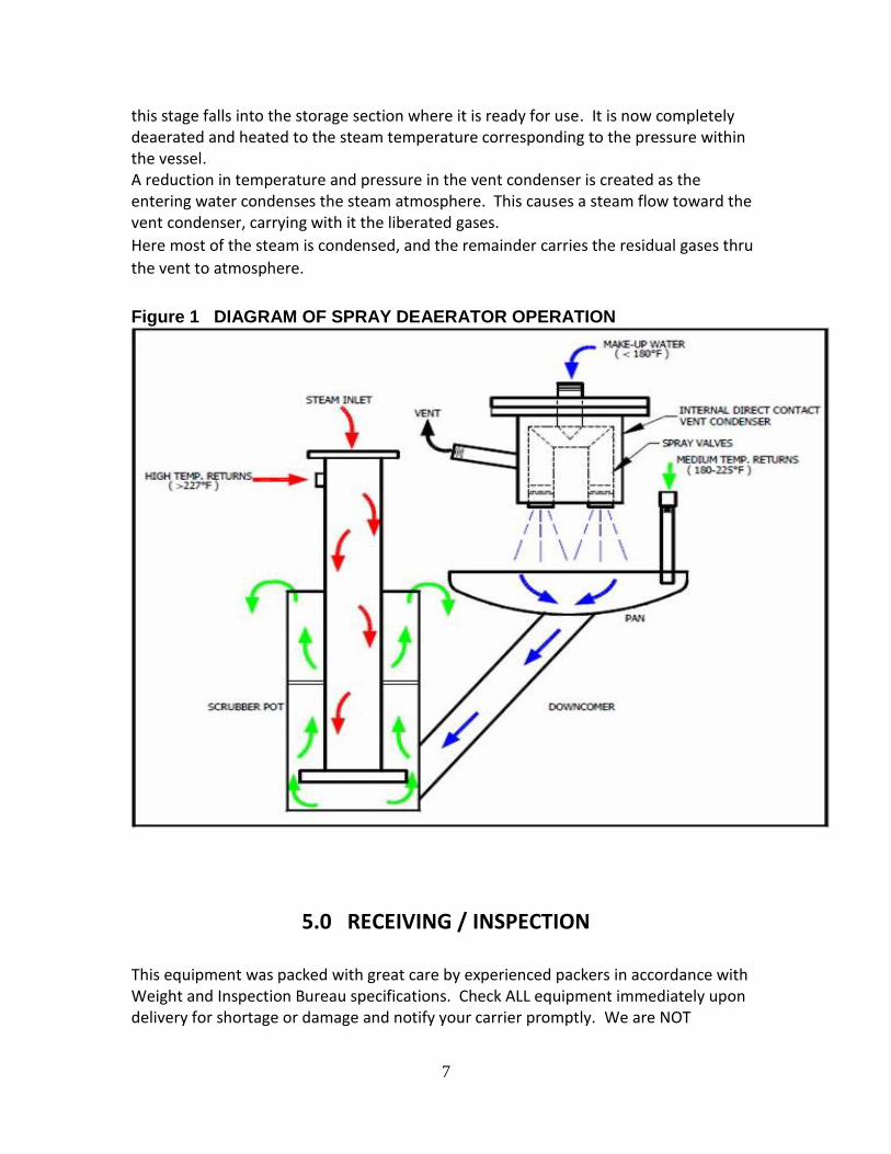
Incoming water first enters the deaerator, thru spray valves, into a steam atmosphere in
the first stage preheater section. There, the water is heated to within 2 degrees of
steam temperature, removing virtually all of the oxygen and free carbon dioxide. This is
accomplished by spraying the water through self-adjusting spray valves, designed to
produce a uniform, thin, controlled film under all load conditions. These efficient valves
assure a constant temperature and uniform gas removal. From the first stage section, the pretreated water, containing minute traces of dissolved gases, flows into the second stage, or deaerator section. This section consists of either a scrubber or, in tray type units, tray assemblies. Here the water is brought into direct contact with an abundance of fresh, gas free steam. The steam enters this stage and is mixed with the pretreated water. Very little steam is condensed here, as the incoming preheated water has a temperature approaching that of the steam. The water leaving
7
this stage falls into the storage section where it is ready for use. It is now completely deaerated and heated to the steam temperature corresponding to the pressure within the vessel. A reduction in temperature and pressure in the vent condenser is created as the entering water condenses the steam atmosphere. This causes a steam flow toward the vent condenser, carrying with it the liberated gases.
Here most of the steam is condensed, and the remainder carries the residual gases thru
the vent to atmosphere.
Figure 1 DIAGRAM OF SPRAY DEAERATOR OPERATION
5.0 RECEIVING / INSPECTION This equipment was packed with great care by experienced packers in accordance with Weight and Inspection Bureau specifications. Check ALL equipment immediately upon delivery for shortage or damage and notify your carrier promptly. We are NOT
8
responsible for damages which occur in transit. Store the equipment in a clean, dry area.
5.1 INSTALLATION 5.1.1 Accessibility Entire systems should be positioned to permit access to operating controls, instruments, and inspection openings. Additional space should be allotted, if necessary, for platforms and ladders required for otherwise inaccessible areas.
5.1.2 Foundations Deaerator foundations need not be as massive as those required by rotating or reciprocating machinery. The foundation should be level and designed to support the anticipated load. Calculations should be based upon the maximum or flooded weight of the entire system including allowances for attachments. 5.1.3 Rigging Qualified riggers should be used to place the system on the foundation. Slings, blocks and all rigging equipment must be carefully placed to avoid damaging or loosening piping, nozzles and other parts of the assembly. The system should be securely bolted to the foundation and shimmed if necessary. 5.1.4 Piping Prior to piping, a thorough internal inspection should be made. All foreign material or debris must be removed to prevent possible malfunctions. Care should be taken to avoid imposing piping strain on the vessel or pumps. Provide expansion joints and suitable independently supported pipe hangers where necessary. Isolating valves should be installed to allow for cleaning or repairs. Valve bypasses are recommended around water inlet and steam pressure reducing valves. Vent piping should be vertical and full-size, avoiding any bends or restrictions. To insure continuous venting, a gate valve is factory installed with a pre-drilled orifice in its disc to prevent complete closure. The piping of the steam pressure-reducing valve is crucial to the proper operation of the deaerator. In service, a pressure-reducing valve produces a lower pressure at its outlet than at its inlet, creating a high steam velocity across the valve seat. In most reducing valve installations, sonic velocity will occur. The extreme velocities that must exist across reducing valve seats cannot be tolerated in piping upstream or downstream of the valve. Excessive erosion and noise would result. In systems where noise of steam flow would be a consideration, it is common practice to limit the velocities to between 4,000 and 6,000 feet per minute. The steam velocity chart (Table 1) lists steam capacities in pipes under various pressure and velocity conditions. 5.1.5 Water Inlet Valve 5.1.5.1 Valve with integral float chamber Install valve sub-assembly as shown on drawing with centerline of float chamber at designated operating level. On systems incorporating two valves, one should be located at the operating level, and the second approximately 2” lower. The primary valve will
9
accommodate average flow requirements, with the secondary unit contributing additional capacity to cover entire operating range of the system. 5.1.5.2 Valve with internal float Install rotary shaft packing box in opening indicated on drawing. Gaining access to the interior of the vessel through the manhole, securely attach float rod with float to the internal portion of the rotary shaft. Mount balancing lever on external portion of rotary shaft and clamp counterweight so that float will be half submerged. This position is established when force is required to either lift or submerge the float. 5.1.5.3 Valve with separate external float operator (mechanical type) Install external float operator at opening level as shown on drawing. Connect turnbuckle assembly to float operator arm and valve lever and adjust as described above. 5.1.5.4 Valve with external float operator (pneumatic type) Install external float operator at opening levels as shown on drawing. Connect pneumatic control tubing between float operator and valve actuator. Adjust actuator as described in instructions accompanying operator and valve assemblies. 5.1.6 Overflow Trap This should be installed at floor level or as low as possible below the deaerator, for maximum static head, assuring the greatest flow. 5.1.7 Insulation The deaerator, storage tank, and all equipment carrying hot water or steam should be thoroughly insulated to prevent condensation of steam and loss of heat. Sample connection, thermometer wells and manholes should be left exposed. 5.2 Deaerator Flows 5.2.1 Make-Up Water Make-up water pressure must be sufficient to overcome the head losses by internal steam pressure, pipe friction, water inlet control and spray valves. 5.2.2 Low Temperature Returns Condensate returns 30°F below the deaerator operating temperature, or cooler, should be piped into the opening provided (as shown on drawing) between the water inlet control valve and the spray valve. This permits the water to pass through the complete deaeration cycle; and it is given preference over raw make-up. 5.2.3 Medium Temperature Returns Returns having a temperature ranging from 30°F below, up to the deaerator operating temperature should be piped to this opening. 5.2.4 High Temperature Returns This opening is used for returns having a temperature higher than that of the steam within the deaerator. They enter directly into the steam entrance of the scrubber where they flash to steam and are utilized in the deaeration process. 5.2.5 Oil Contaminated Returns If exhaust steam comes from reciprocating units such as pumps, engines or compressors, it may contain entrained oil, which must be removed by an oil separator. The oil separator must be of adequate size for maximum steam flow. It should be preceded by a straight pipe equal in length to at least four pipe diameters to prevent
10
turbulence at separator inlet. Connect oil separator drain line to a trap or pipe loop seal. 5.2.6 Steam Steam is required to heat and deaerated water. Thermodynamic laws determine the quantity of steam necessary for deaeration. In order to accurately calculate the required steam it is necessary to set up a heat balance. The steam consumed by a deaerator consists of that needed to raise the temperature of incoming water to the saturated temperature within the vessel, plus carrier steam utilized in vented noncondensables. This quantity is reduced by the introduction of flash steam from high temperature returns. Heat balance calculations should be made using the lowest incoming water temperatures.
The following procedures may be used to calculate steam requirements: ‘A’ and ‘B’ are approximations. ‘C’ is an exact method. Other established procedures are acceptable.
5.2.6.1 Definitions Q – Total deaerated outlet capacity (# / hr.) Qm – Inlet water (under consideration) (# / hr.) Qf – Condensate (flashing) (# / hr.)
P – Steam pressure (psi) T1 – Steam temperature (saturated temperature at inlet pressure) (°F) T2 – Water temperature (°F) Hf and Hfg – Enthalpy (at steam pressure, see any steam table) 5.2.6.2 Procedures Sum all of the flows of required steam for inlet water heating and deduct any steam flashed from hot condensate. This sum will be the maximum steam volume required by the deaerator for the load in question. The procedure may be reversed and solved for any amount of make-up required. 5.2.6.2.1 If the operating steam pressure is between 1 and 5 psig and if the maximum combined inlet water temperature is below 100°F, the steam required will be one seventh of the outlet flow.
11
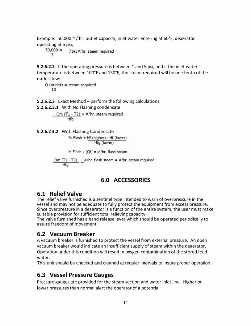
Example: 50,000 # / hr. outlet capacity, inlet water entering at 60°F, deaerator operating at 5 psi;
5.2.6.2.2 If the operating pressure is between 1 and 5 psi, and if the inlet water temperature is between 100°F and 150°F, the steam required will be one tenth of the outlet flow:
5.2.6.2.3 Exact Method – perform the following calculations: 5.2.6.2.3.1 With No Flashing condensate
5.2.6.2 3.2 With Flashing Condensate
6.0 ACCESSORIES 6.1 Relief Valve The relief valve furnished is a sentinel type intended to warn of overpressure in the vessel and may not be adequate to fully protect the equipment from excess pressure. Since overpressure in a deaerator is a function of the entire system, the user must make suitable provision for sufficient total relieving capacity. The valve furnished has a hand release lever which should be operated periodically to assure freedom of movement. 6.2 Vacuum Breaker A vacuum breaker is furnished to protect the vessel from external pressure. An open vacuum breaker would indicate an insufficient supply of steam within the deaerator. Operation under this condition will result in oxygen contamination of the stored feed water. This unit should be checked and cleaned at regular intervals to insure proper operation.
6.3 Vessel Pressure Gauges Pressure gauges are provided for the steam section and water inlet line. Higher or lower pressures than normal alert the operator of a potential

12
problem.
13
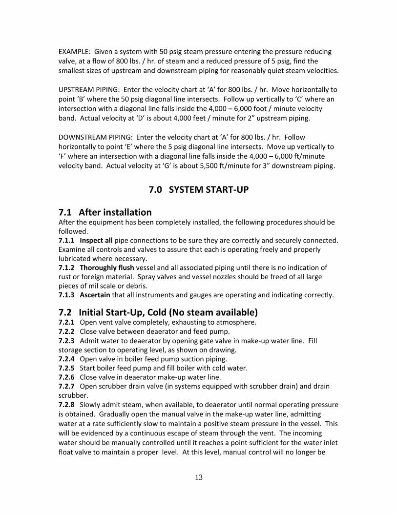
EXAMPLE: Given a system with 50 psig steam pressure entering the pressure reducing valve, at a flow of 800 lbs. / hr. of steam and a reduced pressure of 5 psig, find the smallest sizes of upstream and downstream piping for reasonably quiet steam velocities. UPSTREAM PIPING: Enter the velocity chart at ‘A’ for 800 lbs. / hr. Move horizontally to point ‘B’ where the 50 psig diagonal line intersects. Follow up vertically to ‘C’ where an intersection with a diagonal line falls inside the 4,000 – 6,000 foot / minute velocity band. Actual velocity at ‘D’ is about 4,000 feet / minute for 2” upstream piping. DOWNSTREAM PIPING: Enter the velocity chart at ‘A’ for 800 lbs. / hr. Follow horizontally to point ‘E’ where the 5 psig diagonal line intersects. Move up vertically to ‘F’ where an intersection with a diagonal line falls inside the 4,000 – 6,000 ft/minute velocity band. Actual velocity at ‘G’ is about 5,500 ft/minute for 3” downstream piping.
7.0 SYSTEM START-UP
7.1 After installation After the equipment has been completely installed, the following procedures should be followed. 7.1.1 Inspect all pipe connections to be sure they are correctly and securely connected. Examine all controls and valves to assure that each is operating freely and properly lubricated where necessary. 7.1.2 Thoroughly flush vessel and all associated piping until there is no indication of rust or foreign material. Spray valves and vessel nozzles should be freed of all large pieces of mil scale or debris. 7.1.3 Ascertain that all instruments and gauges are operating and indicating correctly. 7.2 Initial Start-Up, Cold (No steam available) 7.2.1 Open vent valve completely, exhausting to atmosphere. 7.2.2 Close valve between deaerator and feed pump. 7.2.3 Admit water to deaerator by opening gate valve in make-up water line. Fill storage section to operating level, as shown on drawing. 7.2.4 Open valve in boiler feed pump suction piping. 7.2.5 Start boiler feed pump and fill boiler with cold water. 7.2.6 Close valve in deaerator make-up water line. 7.2.7 Open scrubber drain valve (in systems equipped with scrubber drain) and drain scrubber. 7.2.8 Slowly admit steam, when available, to deaerator until normal operating pressure is obtained. Gradually open the manual valve in the make-up water line, admitting water at a rate sufficiently slow to maintain a positive steam pressure in the vessel. This will be evidenced by a continuous escape of steam through the vent. The incoming water should be manually controlled until it reaches a point sufficient for the water inlet float valve to maintain a proper level. At this level, manual control will no longer be
14
necessary, but the float control should be checked for proper operation. Make any adjustments which may be required to maintain specified operating levels.
7.2.9 When a considerable volume of steam is issuing from the vent, throttle back the vent valve until only a plume of vapor can be seen. The water temperature at this point should rise to within three degrees of saturation temperature of the steam at the observed deaerator operating pressure. A lower temperature would indicate insulating pockets of air in the vessel. If this occurs, open the vent valve completely for a few seconds to purge this air from the deaerator. Return the vent valve to its original position. 7.2.10 Open steam valve fully. 7.2.11 When water temperature rises to within two degrees of steam temperature, the system is ready for service. The pump suction valves may be opened and the vent valve
should be adjusted in accordance with Section 7. During operation, stored water temperature should correspond to that of saturated steam at the deaerator operating pressure. 7.2.12 Check all valves and float controls to be sure proper water level is maintained. 7.2.13 Some rumbling may occur with a cold tank. This should disappear as temperature levels increase. Entrapped air is another possible source of rumbling; this should be eliminated as described in 5.2.9. During operation, stored water temperature should correspond to that of saturated steam at the deaerator operating pressure. 7.2.14 When proper operating temperature has been achieved, recheck all piping, flange and manhole bolts, etc. for tightness. 7.3 Initial start-up, hot (steam available) 7.3.1 Open vent valve completely, exhausting to atmosphere. 7.3.2 Open steam valve slowly, gradually bring deaerator up to operating pressure. If pressure – reducing valve hunts or pulsates, adjust until pressure remains steady. 7.3.3 Gradually admit water to deaerator by partially opening the gate valve in the water inlet line. The rates of steam and water flow should be carefully controlled to maintain a positive steam pressure in the vessel. This will be evidenced by a continuous escape of steam through the vent. Water flow should be manually controlled until it reaches a point sufficient for the water inlet float valve to maintain a proper level. At this level, manual control will no longer be necessary, but the float control should be checked for proper operation. Make any adjustments which may be required to maintain specified operating levels. 7.3.4 At this stage, refer to Section 5.2.9, (in Initial start-up, cold.
7.4 Venting Vent valve is furnished with an orifice in its gate. This orifice is sized for minimum venting. Heavy concentrations of removed gases may require that the valve be opened wider to permit their release to atmosphere. Water temperatures lower than that of saturated steam at the deaerator operating pressure would indicate insufficient venting.

15
The vent valve opening should be adjusted accordingly until proper temperature is indicated.
8.0 SHUT-DOWN
8.1 Temporary (overnight, weekend, etc.) Recommended procedure is to allow deaerated water to remain in storage section while maintaining steam pressure in the vessel. Close water inlet and outlet valves. 8.2 Long Term Idle Periods The deaerator may be shut-down completely with no steam pressure in the unit. Deaerated water may remain in the vessel. Water inlet valve must be closed before eliminating steam pressure. Cold water entering the unit will condense the steam, causing a vacuum condition, which could result in collapse of the vessel.
9.0 START-UP AFTER SHUT-DOWN
9.1 Pressure maintained When steam pressure has been maintained in the deaerator during temporary shutdown, it is only necessary to open the water inlet valve and gradually bring flow to required capacity. Recheck adjustments to maintain proper operating levels, and open outlet valve.
9.2 Pressure not maintained When steam pressure has not been maintained, first drain scrubber completely, close valve and proceed in accordance with Section 5.2 or 5.3 (START-UP) as appropriate. CAUTION: The above described procedures must be followed to prevent oxygen contamination of stored water, water hammer and rumble in the deaerator scrubber section.
10.0 OPERATING RECORD
A per shift or per day record of deaerator steam and water pressures, and temperatures should be maintained. Inspection of all gauges and controls for proper operation should be made at the same intervals.
11.0 MAINTENANCE
11.1 Vessel 11.1.1 Bi-weekly Clean gauge glasses and inspect all controls for proper operation. Lubricate all moving parts as required.
16
11.1.2 After first month of operation Check spray valves for foreign matter, which may have accumulated from new piping. Clean if necessary. 11.1.3 Semi-Annually 11.1.3.1 Inspect spray valves and preheater section for scale or dirt (thin scale formations will not affect efficiency). Remove any accumulation of debris or scale if necessary. 11.1.3.2 Clean oil separator trap if employed. 11.1.3.3 Inspect relief valve and vacuum breaker for proper operation. 11.1.4 Annually 11.1.4 1 Drain storage section and remove manhole. Flush out all sediment in storage section and follow with manual cleaning, if necessary. Make certain pump suction openings and piping are clean. 11.1.4.2 Inspect scrubber section. Flush out sediment through scrubber drain.
11.1.5 Frequently Check deaerator gauge glasses frequently for the presence of oil. Oil is more damaging than scale in a boiler. If detected, immediate steps must be taken to find its source an eliminate it (Refer Section 12.0-Troubleshooting). After the cause has been found and rectified, the deaerator should be drained and thoroughly cleaned before being returned to service.
11.2 Pumps 11.2.1 Packing Check packing glands – DO NOT run dry. Permit a few drops of water per minute to drop from glands. This provides lubrication for the shaft, eliminating burned packing and scored shafts. When tightening gland bolts, do so ONLY when pump is running. Draw up evenly 1/4 turn at a time to allow gland pressure to equalize throughout stuffing box. Replace with Hi-temp packing after six (6) months to one (1) year, depending upon
severity of service. Remove all old packing first (do not intermix new and old packing). Insert individual rings so that splices are staggered. When stuffing box is full, adjust gland just tight enough to permit slight leakage as described above – DO NOT RUN DRY. 11.2.2 Bearings These will require periodic lubrication, using the grease fittings in the pump frame. For 8 hours daily operation, this should be every thousand hours. Use ball bearing grease of high quality; lithium, lithium soda or calcium base grease is recommended for both wet and dry locations. Do not mix different brands. Avoid over lubrication, which can result in overheating and bearing failure. Adequate lubrication is assured if grease quantity is maintained at to the capacity of the bearing. Approximately every six (6) months, bearing should be cleaned by flushing with kerosene and relubricated.

17
12.0 TROUBLESHOOTING
12.1 Low Temperature The only reasons for a deaerator to operate at less than saturated steam temperature are lack of steam or improper venting: 12.1.1 Insufficient steam Insufficient steam may result from an undersized pressure reducing valve or an insufficient supply of steam due to other causes. The pressure-reducing valve furnished is sized for specific pressures, temperatures, percentages of returns and make-up water. Changes in these values will affect its operation. 12.1.2 Insufficient venting Insufficient venting can be traced to the vent valve and its associated piping. This valve is furnished with an orifice in its disc for minimum venting. Rapid accumulation of released gases may require that the valve be opened wider to accommodate their evacuation to atmosphere. Low water temperature is an indication of insufficient venting. Adjust valve opening accordingly. Vent piping must be vertical, full size, and free of bends or obstructions. No other valves should be installed in this line.
12.2 Vibration, Rumble and Hammer These can be caused by low steam pressure or blockage of internal steam passages in the deaerator. 12.2.1 Low steam pressure Low steam pressure may result from an undersized pressure reducing valve, improper steam piping, malfunction of the pressure reducing valve or an insufficient supply of steam. Check size, capacity, proper operation of pressure reducing valve as well as steam supply and pressure.
12.3 Oil Contamination A likely source would be one of the following: 12.3.1 Condensate Condensate contaminated by oil, possibly from a leaking heat exchanger. 12.3.2 Improper grade of oil Improper grade of oil used in steam driven equipment. 12.3.3 Oil separator not draining properly. After locating and rectifying the cause, the deaerator must be drained and thoroughly cleaned before returning to service. 12.4 Water Level 12.4.1 Wide fluctuations Wide fluctuations in water level are to be avoided since they may cause rumbling or variations in both temperature and pressure. They following precautions should be observed:
18
12.4.1.1 Check water inlet valve Check water inlet valve for proper operation. Water supply pressures differing from those originally specified will result in inadequate or erratic supply. Remedy by using a properly sized valve or adjusted water supply pressure. 12.4.1 2 Sudden slugs of water Sudden slugs of water will cause severe variations in steam pressure. These can be the result of large volume returns from a condensate pump, or an oversized water inlet valve. Inlet water flows should be as smooth as possible to avoid sudden steam pressure drops, which will cause flashing and cavitation in the boiler feed pumps. 12.4.1.3 Water flows Make certain that total water flows (returns and make-up) do not exceed rated deaerator capacity. 12.5 Pumps Unusual noise may be caused by several factors, as follows: 12.5.1 Cavitation At any given temperature, all liquids have a definite pressure at which they will boil. It follows, therefore, that a liquid will boil at any temperature, if the pressure is reduced sufficiently. All pumps have a specific net positive suction heat (NPSH) requirement. If this positive head is not available, pump cavitation will develop, resulting in severe damage. The required NPSH has been provided in this system, including additional height to overcome suction line friction losses. Suction piping is intentionally oversized to further reduce these losses. Any unusual restriction, such as a clogged strainer, in the suction piping will cause cavitation. The existence of such an obstruction can best be determined by a thorough visual check or by installing a compound gauge (reading in vacuum and pressure) in the pump suction line close to the pump. A thoroughly clean unrestricted line will produce a pressure reading on the gauge, while the pump is running, equal to the operating pressure of the deaerator plus the static head available. This head is measured in feet from the water level to the pump suction centerline and converted to PSIG by dividing by 2.31. A slight variance may be observed due to friction losses in suction piping. Any restriction must be corrected immediately or severe pump damage will result. The required NPSH has been provided in this system, including additional height to overcome suction line friction losses. Suction piping is intentionally oversized to further reduce these losses. Any unusual restriction, such as a clogged strainer, in the suction piping will cause cavitation. The existence of such an obstruction can best be determined by a thorough visual check or by installing a compound gauge (reading in vacuum and pressure) in the pump suction line close to the pump. A thoroughly clean unrestricted line will produce a pressure reading on the gauge, while the pump is running, equal to the operating pressure of the deaerator plus the static head available. This head is measured in feet

19
from the water level to the pump suction centerline and converted to PSIG by dividing by 2.31. A slight variance may be observed due to friction losses in suction piping. Any restriction must be corrected immediately or severe pump damage will result. 12.5.2 Misaligned coupling Another source of noise would be a misaligned coupling between pump and motor. Check this by applying a straight edge across coupling halves at 90º and 180º. Straight edge should rest evenly on both coupling halves. Shim pump and/or motor, if necessary, to bring coupling into perfect alignment vertically and laterally. Check pump for free rotation by turning coupling manually. 12.5.3 Pipe alignment Be sure piping connections at pump are properly aligned and supported to eliminate any strain on pump casing. Forcing piping into place will result in misalignment of pump, causing noise and structural damage. 12.5.4 Vibration Vibration can be induced by bent or broken shafts, worn bearings, or binging of the impeller due to foreign matter entering the pump. Worn or damaged shafts and bearings must be replaced. Remove any contaminants in the pump and replace damaged parts. It is essential that the source of contamination by found and eliminated BEFORE returning the pump to service. 12.6 Overflow An overflow condition may result from malfunction of the trap or the water inlet valve. 12.6.1 Inspect trap for accumulated dirt at the valve seat and clean, if necessary. Periodically remove the drain plug and drain sediment. 12.6.2 If trap is functioning properly, inspect water inlet float for possible water-logged condition. Make certain that water inlet valve control linkage is properly adjusted to maintain specified operating level in deaerator. 12.7 Motors Any number of reasons exists for motor failure. Some of the most common are as follows: 12.7.1 Tripped starter overload – Reset and check motor and pump for proper operation. 12.7.2 Improper power supply – Check voltage and motor nameplate requirements. 12.7.3 Incorrect connections – Check wiring diagram. 12.7.4 Mechanical failure – Check for free rotation; examine bearings. 12.7.5 Short circuited windings – Indicated by blown fuse or failure to start. Motor must be replaced. 12.7.6 Overload – Check pump for proper operation and free rotation. 12.7.7 One phase open in three phase circuit – Check power supply lines. 12.7.8 Vibration 12.7.8.1 Check alignment of pump and motor. 12.7.8.2 Defective bearing – Replace
20
12.7.8.3 Polyphase motor running single phase – Check for open circuit. 12.8 Controls 12.8.1 Blown Fuses 12.8.1.1 Short circuits Check motor for short-circuited windings – Reset and inspect pump and motor for proper operation. 12.8.1.2 Incorrect connections Refer to wiring diagram 12.8.1.3 Improper power supply Check voltage and motor nameplate requirements. 12.8.2 Starter overload tripped Reset and inspect pump and motor for proper operation. 12.8.3 Motor fails to start 12.8.3.1 Make certain boiler level switch is functioning properly. 12.8.3.2 Check control circuit for continuity. 12.8.4 High / low alarm system not operating. 12.8.4 1 Relays defective. 12.8.4.2 High or low alarm switch not operating proper.