installation and operating instructions - spartan controls/media/resources/ametek... · for...
TRANSCRIPT

The Leader of RFand Sonic Level
For Assistance Call 1-800-527-6297Outside North America + 215-674-1234
Installation andOperating Instructions
Series 506-6200Level Control Transmitter (LCT)
using 406-6200 Electronics
�������������� �������� ������������������������������ �����!!!"���#�$%���&"������#�$%���&"���'���(��� �&"���
�������������� ��������������������������������� ������������������ ��� ������ ������������� ���������

AMETEK Drexelbrook makes no warranty of any kind with regard to the material containedin this manual, including, but not limited to, implied warranties or fitness for a particularpurpose. Drexelbrook shall not be liable for errors contained herein or for incidental orconsequential damages in connection with the performance or use of material.
Copyright 2002 AMETEK Drexelbrook

�����������
506-6200-LM
Series 506-6200Level Control Transmitter (LCT)
using 406-6200 Electronics
205 Keith Valley Road Horsham, PA 19044US Sales 1-800-553-909224 Hour Service 1-800-527-6297International + 215-674-1234Fax + 215-674-2731E-mail [email protected] www.drexelbrook.comAn ISO 9001 Certified Company
DREXELBROOK


�����������
�� � �����
Table of Contents
Section 1.0 Introduction................................................................................................. 31.1 System Description................................................................................................... 31.2 Verify System Description ......................................................................................... 4
1.2.1 Circuit Description ........................................................................................ 41.3 Models Available ...................................................................................................... 4
1.3.1 Electronic Units ............................................................................................ 41.3.2 Connecting Cables ....................................................................................... 51.3.3 Sensing Elements ........................................................................................ 51.3.4 Verify System................................................................................................ 5
Section 2.0 Specifications and Intrinsic Safety ............................................................ 62.1 Electronic Unit .......................................................................................................... 62.2 Verify System ............................................................................................................ 62.3 Three-Terminal Connecting Cables .......................................................................... 72.4 Sensing Elements .................................................................................................... 7
Section 3.0 Theory of Operation ................................................................................... 83.1 Electronic Unit .......................................................................................................... 83.2 Cote-Shield Action ................................................................................................... 93.3 Sensing Element ...................................................................................................... 93.4 Connecting Cables ................................................................................................... 103.5 Verify System (optional) ............................................................................................ 10
Section 4.0 Installation ................................................................................................... 124.1 Unpacking ................................................................................................................ 124.2 Mounting the Electronic Unit ..................................................................................... 12
4.2.1 Installation Location and Approval Codes .................................................... 124.3 Mounting the Sensing Element ................................................................................. 13
4.3.1 Flush Sensing Element ................................................................................ 144.4 Mounting the Verify System ...................................................................................... 154.5 Wiring the Electronic Unit ......................................................................................... 154.6 Wiring the Sensing Element ..................................................................................... 164.7 Wiring the Verify System ........................................................................................... 17

Table of Contents (continued)
Section 5.0 Calibration/Operation ................................................................................. 185.1 Start-up ..................................................................................................................... 185.2 Controls and Adjustments ........................................................................................ 18
5.2.1 Setpoint Adjustment without Verify System................................................... 185.2.2 Setpoint Adjustment with Verify System........................................................ 185.2.3 Time Delay Control ...................................................................................... 185.2.4 Fail-Safe Selector ......................................................................................... 19
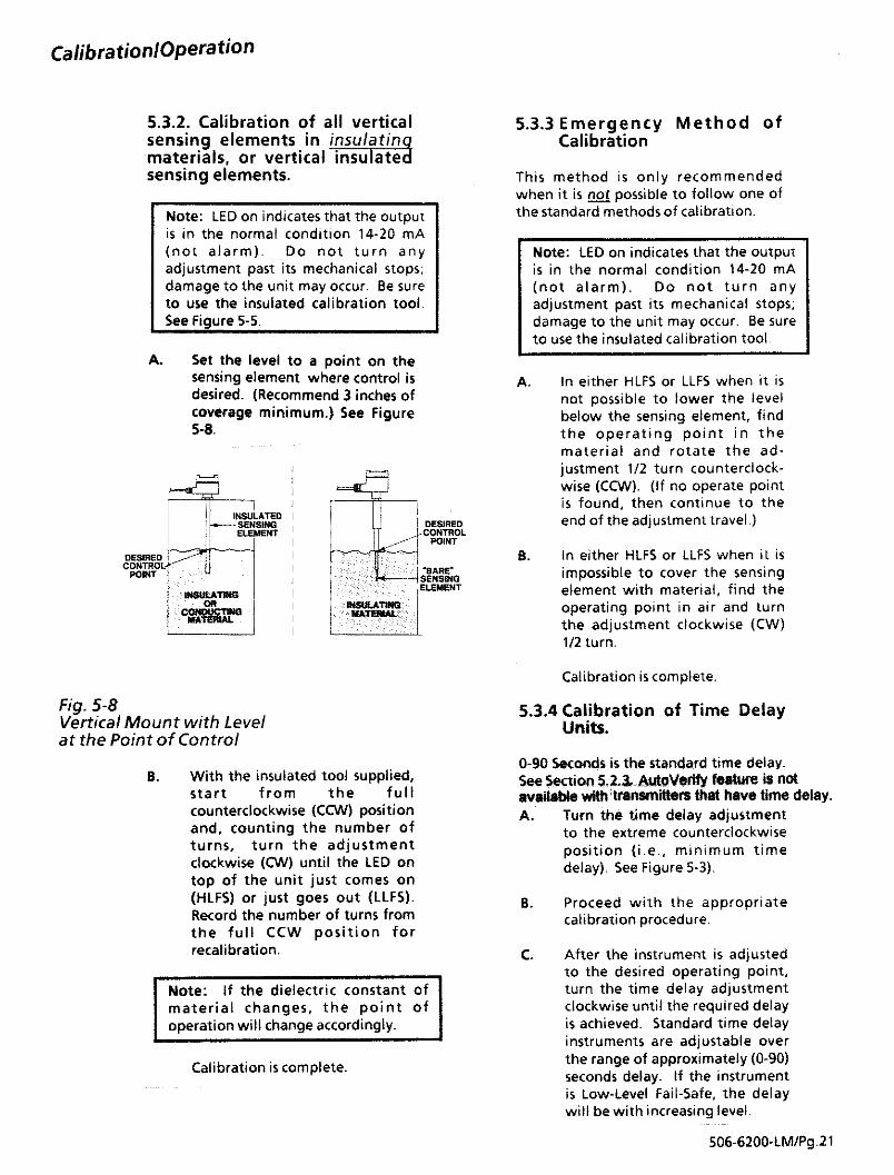
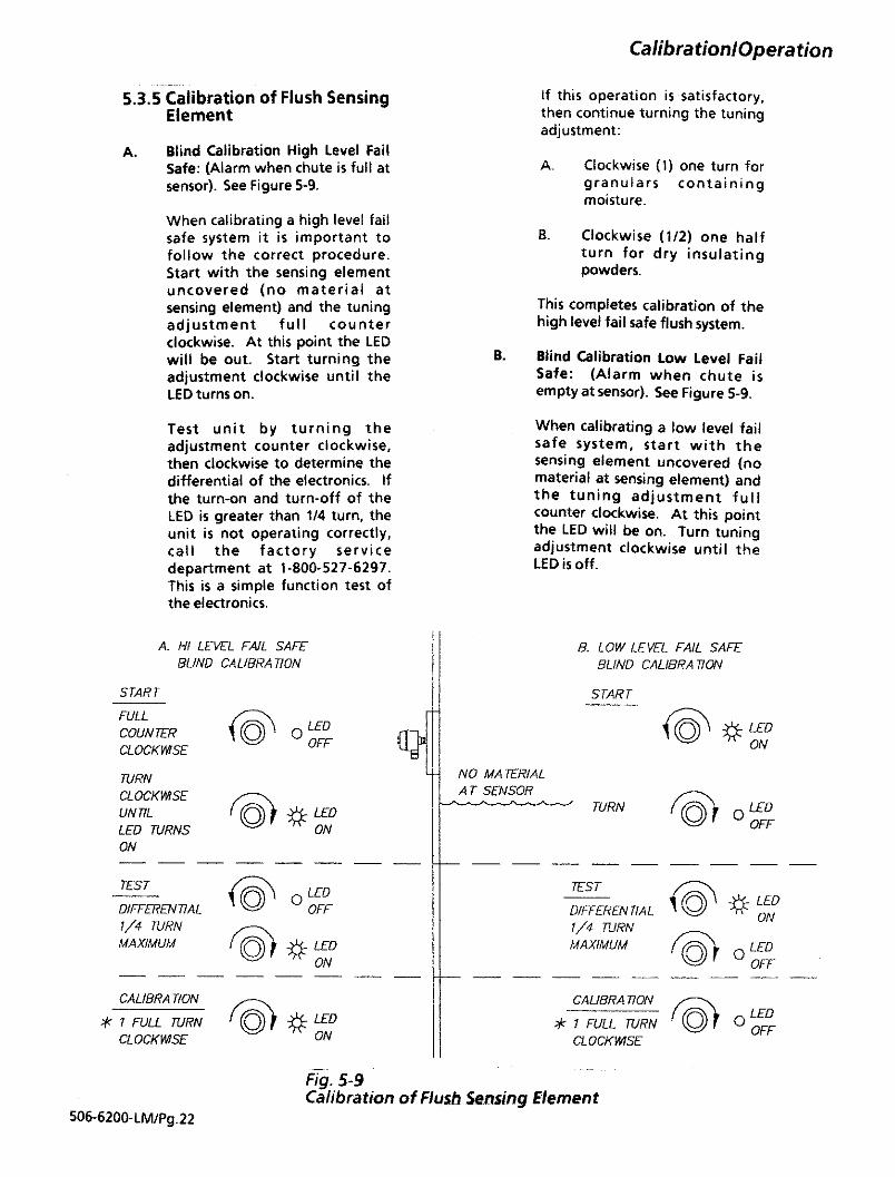
5.3 Calibration Procedures ............................................................................................. 195.3.1 Calibration of Horizontal Sensing Elements ................................................. 195.3.2 Calibration of Vertical Sensing Elements ..................................................... 215.3.3 Emergency Method of Calibration ................................................................ 215.3.4 Calibration of Time Delay Units .................................................................... 215.3.5 Calibration of Flush Sensing Element .......................................................... 22
5.4 Recalibration ............................................................................................................ 235.5 Calibrating with Verify System .................................................................................. 23
Section 6.0 Troubleshooting ........................................................................................... 246.1 Introduction ............................................................................................................... 246.2 Testing the LCT Electronics ...................................................................................... 246.3 Testing the LCT Electronics with Verify ..................................................................... 246.4 Testing the Cote-ShieldTM Sensing Element .............................................................. 25
6.4.1 Level Below the Sensing Element ................................................................ 256.4.2 Level Above the Sensing Element ............................................................... 26
6.5 Checking the Sensing Element Cable ...................................................................... 276.6 Possible Problems with Probable Causes ................................................................ 28
Section 7.0 Factory Support ........................................................................................... 297.1 Factory Assistance ................................................................................................... 297.2 Field Service ............................................................................................................ 297.3 Customer Training..................................................................................................... 297.4 Equipment Return......................................................................................................30
Appendix AShortening or Lenghtening Sensing Element
Appendix BFM & CSA Control Drawings


WR
ON
GC
OR
RE
CT C
ON
DU
ITB
RE
AT
HE
RD
RA
IN
WR
ON
GC
OR
RE
CT
**
Allo
ws
Moi
stur
e In
filtr
atio
nU
se o
nly
cabl
e su
pplie
d by
AM
ET
EK
D
rexe
lbro
ok
All
cond
uit c
onne
ctio
ns �
are
seal
ed. �
Gas
kets
are
in p
lace
.
Fill
Pip
e E
nds
with
�si
licon
e se
alan
t.
CO
ND
UL
ET
Pac
king
Gla
nd �
Ass
embl
yD
o N
ot D
istu
rb!
Hol
d he
re w
hile
�tig
hten
ing
cond
ulet
.
Hol
d he
re to
inst
all �
or r
emov
e se
nsin
g �
elem
ent f
rom
ves
sel.
*
Pag
e 5A


Installation
4.4 Mounting the Verify System:401-10-220 Pulse Recognition Module401_10_210 Verify Switch Module
For mounting, see Figures 4-4 and 5-5. The401-10-220 pulse recognition module ismounted directly onto the 406-6200 Seriestransmitter on the power/signal connection side.
The 401-210 Verify Switch module can bemounted on a standard 35mm DIN rail orscrew-mounted to a panel.
4.5 Wiring the Electronic Unit
All signal and power connections are made tothe terminal strip on the 406-6200 Serieschassis. These connections are (+), (-), comm,and ground. See Figure 4-6. If signal wirescannot be referenced to circuit ground, pleaseconsult factory.
The sensing element cable connections aremade to the back of the instrument chassis.These connections are labled ground (GND),shield (SH), and center wire (CW). See Figure4-7.
Wiring to PLC or DCS w/ Non-isolated InputsThe negative side of loop is grounded to thechassis (housing) at the electronic unit. Ifconnecting this product to an instrument that isgrounded OTHER THAN at the negative inputterminal, contact Drexelbrook ServiceDepartment at 1-800-527-6297 (US & Canada;all others call 1-215-674-1234).
Note: The electronic unit has a grounding linkbetween the ground and common terminals.The link is reqired for hazardous areaoperation and should not be removed beforeconsulting the factory.
GND(Green)
Pulse ModuleAssembly
406-6200 Series Transmitter
Pad A(Black)
Pad B(Blue)
Shield B(Red)
Fig. 4-4Mounting the 401-10-220Pulse Recognition Module
Fig. 4-6Signal Wiring toElectronic Unit
Module mounts tostandard 36mm DIN rail
3.56(90)
2.68(68) 2.18
(55.3)
Signal Wiring(Typical)
For wiring diagrams withWith Verify System, seeFigures 4-10 and 4-11
GroundWire
(Green)
Shield Wire(Red)
Center Wire(Blue)
Fig. 4-7Sensing Element Connectionsto the Electronic Unit
Fig. 4-5Mounting the 401-10-210Verify Switch Module


7.1 Factory AssistanceAMETEK Drexelbrook can answer any questions about yourlevel measurement system. Call Customer Service at1-800-553-9092 (US and Canada) , or + 215-674-1234 (International).
If you require assistance and attempts to locate the problemhave failed:•• •• • Contact your local Drexelbrook representative,•• •• • Call the Service department toll-free at 1-800-527-6297
(US and Canada) or + 215-674-1234 (International),•• •• • FAX the Service department at + 215-443-5117, or•• •• • E-Mail to [email protected]
Please provide the following information:
Instrument Model Number ___________________________
Sensing Element Model Number and Length ___________
Original Purchase Order Number _____________________
Material being measured _____________________________
Temperature __________________________________
Pressure ______________________________________
Agitation ______________________________________
Brief description of the problem _______________________________________________________________________________________________________________________________
Checkout procedures that have failed __________________________________________________________________________________________________________________________
7.2 Field ServiceTrained field servicemen are available on a time-plus-ex-pense basis to assist in start-ups, diagnosing difficult applica-tion problems, or in-plant training of personnel. Contact theservice department for further details.
7.3 Customer TrainingPeriodically, AMETEK Drexelbrook instrument training semi-nars for customers are held at the factory. These sessions areguided by Drexelbrook engineers and specialists, and providedetailed information on all aspects of level measurement, in-cluding theory and practice of instrument operation. For moreinformation about these valuable workshops, write toAMETEK Drexelbrook, attention:Communications/ Training Group, or call direct + 215-674-1234.
7.0 Factory Support
506-6200-LM/Pg.29

7.4 Equipment ReturnIn order to provide the best service, any equipment beingreturned for repair or credit must be pre-approved by thefactory.
In many applications, sensing elements are exposed to haz-ardous materials.•• •• • OSHA mandates that our employees be informed and
protected from hazardous chemicals.•• •• • Material Safety Data Sheets (MSDS) listing the
hazardous materials to which the sensing element hasbeen exposed MUST accompany any repair.
•• •• • It is your responsibility to fully disclose all chemicals anddecontaminate the sensing element.
To obtain a return authorization (RA#) , contact the Servicedepartment at 1-800-527-6297 (US and Canada) or + 215-674-1234 (International).Please provide the following information:
Model Number of Return Equipment ____________________
Serial Number _________________________________________
Original Purchase Order Number _______________________
Process Materials that equipment has been exposedto_____________________________________________________
MSDS sheets for any hazardous materials
Billing Address ______________________________________________________________________________________________
Shipping Address ____________________________________________________________________________________________
Purchase Order Number for Repairs _____________________
Please include a purchase order even if the repair is underwarranty. If repair is covered under warranty, you will not becharged.
Ship equipment freight prepaid to:AMETEK-DREXELBROOK.205 KEITH VALLEY ROADHORSHAM, PA 19044-1499COD shipments will not be accepted.
506-6200-LM/Pg.30


Insulators Note:Cote-Shieldelement mustNEVER beModified!
Inse
rtio
n Le
ngth
(18
" or
36"
std
.)
Center RodNote: Any changes to probelength after calibration requiresrecalibration to insure properoperation!
CAUTION:The insulation length ofeither Flush SensingElements or InsulatedSensing Elements canNOT be changed.Cable sensing elementscan only be shortened andinstructions are includedwith each unit.
The NeedSometimes your application calls for probe lengths otherthan the standard 18-inch or longer insertion lengthssupplied. Shortening the sensing element is quite simpleand can be done in the field. Lengthening the sensingelement, however, is more difficult because the metal rod,typically 304SS or 316SS, must be welded.
Before making any Adjustments:1) Read the following instructions thoroughly.2) Remove Power3) Disconnect the electronics.4) Protect electronics from any static discharge.5) Protect electronics from any heat.
ShorteningThe bare metal center rod of the sensing element can beshortened with a hacksaw. Be careful not to cut either ofthe two insulators. See Figure on this page.
In applications using conductive or water-based materials,shortening is not a problem. Leave a minimum baremetal center rod length of two (2) inches.
For dry granular materials, such as powder, sand, corn,clinker, etc., you must leave a minimum bare metal centerrod length of eight (8) inches. Consult the factory beforeshortening beyond this point.
LengtheningTo lengthen the sensing element, an extension rod can bewelded onto the end of the bare metal center rod. Makesure that the extension rod is the same metal as thesensing element.
An alternate option is to add a pipe coupling and a sectionof metal pipe after threading the tip of the sensing ele-ment. In this case, the metal pipe need not be identical tothe metal of the sensing element.
APPENDIX A
Shortening or Lengthening Sensing Element
A-1
506-6200 Series LCT
C-1
APPENDIX BAPPROVAL DRAWINGS
These drawings are on the the pages following this sheet:
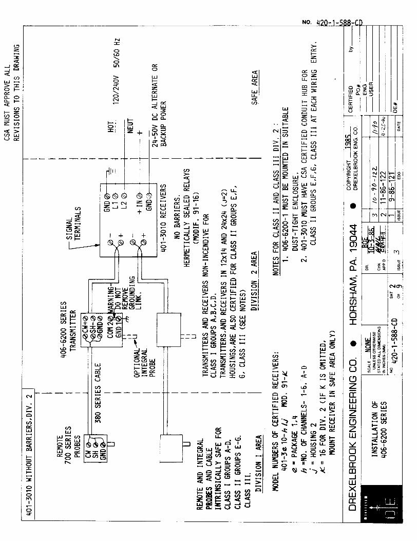
CSA Control Drawings for 406-6200 Series Transmitter 420-0001-588-CD
FM Control Drawings for 406-6200 Series Transmitte 420-0001-813-CD


205 Keith Valley Road Horsham, PA 19044US Sales 1-800-553-909224 Hour Service 1-800-527-6297International + 215-674-1234Fax + 215-674-2731E-mail [email protected] www.drexelbrook.comAn ISO 9001 Certified Company
DREXELBROOK