installation and operation manual...grandprix two-post lifts 5 p/n 5900209 — rev. d2 — may 2019...
TRANSCRIPT

1645 Lemonwood Dr. Santa Paula, CA 93060 USA
Toll Free: (800) 253-2363 Telephone: (805) 933-9970
bendpak.com
GrandPrix Two-Post Lifts
Installation and Operation Manual Manual P/N 5900209 — Manual Revision D2 — May 2019
Models:
• GP-7
• GP-7LC
• GP-7LCS
Model GP-7 shown.
Designed and engineered by BendPak Inc. in Southern California, USA. Made in China.
⚠ DANGER Read the entire contents of this manual before using this product. Failure to follow the instructions and safety precautions in this manual can result in serious injury or death. Make sure all other operators also read this manual. Keep the manual near the product for future reference. By proceeding with setup and operation, you agree that you fully understand the contents of this manual.

Manual. GrandPrix Series Two-Post Lifts, Installation and Operation Manual, Manual P/N 5900209, Manual Revision D2, Released May 2019.
Copyright. Copyright © 2019 by BendPak Inc. All rights reserved. You may make copies of this document if you agree that: you will give full attribution to BendPak Inc., you will not make changes to the content, you do not gain any rights to this content, and you will not use the copies for commercial purposes.
Trademarks. BendPak and the BendPak logo are registered trademarks of BendPak Inc. The GrandPrix logo is a trademark of BendPak Inc. All other company, product, and service names are used for identification only. All trademarks and registered trademarks mentioned in this manual are the property of their respective owners.
Limitations. Every effort has been made to ensure complete and accurate instructions are included in this manual. However, product updates, revisions, and/or changes may have occurred since this manual was published. BendPak reserves the right to change any information in this manual without incurring any obligation for equipment previously or subsequently sold. BendPak is not responsible for typographical errors in this manual.
Warranty. The BendPak warranty is more than a commitment to you: it is also a commitment to the value of your new product. Contact your nearest BendPak dealer or visit www.bendpak.com/support/warranty for full warranty details. Go to bendpak.com/support/register-your-product/ and fill out the online form to register your product (be sure to click Submit).
Safety. Your new product was designed and manufactured with safety in mind. Your safety also depends on proper training and thoughtful operation. Do not set up, operate, maintain, or repair the unit without reading and understanding this manual and the labels on the unit.
Owner Responsibility. In order to maintain your product properly and to ensure operator safety, it is the responsibility of the product owner to read and follow these instructions: • Follow all installation, operation, and maintenance instructions. • Make sure product installation conforms to all applicable local, state, and federal codes, rules, and regulations,
such as state and federal OSHA regulations and electrical codes. • Read and follow all safety instructions. Keep them readily available for operators. • Make sure all operators are properly trained, know how to safely operate the unit, and are properly supervised. • Do not operate the product until you are certain that all parts are in place and operating correctly. • Carefully inspect the product on a regular basis and perform all maintenance as required. • Service and maintain the unit only with approved replacement parts. • Keep the manual with the product and make sure all labels are clean and visible. Unit Information. Enter the Model Number, Serial Number, and the Date of Manufacture from the label on your unit. This information is required for part or warranty issues. Model: Serial: Date of Manufacture:

GrandPrix Two-Post Lifts 3 P/N 5900209 — Rev. D2 — May 2019
Table of Contents Introduction 3 Installation 13 Shipping Information 3 Operation 51 Safety Considerations 4 Maintenance 54 FAQ 6 Troubleshooting 56 Specifications 7 Wiring / Hydraulic Schematic 57 Components 10 Parts Diagrams 58 Installation Checklist 12 Labels 67
Introduction This manual describes the GrandPrix (GP-7 Series) two-post Lifts from BendPak:
• GP-7. Two-post Lift, 7,000 lb. capacity, 74 inch rise, requires a 13-foot ceiling. • GP-7LC. Two-post Lift, 7,000 lb. capacity, 64 inch rise, needs only a 10-foot ceiling. • GP-7LCS. Two-post Lift, 7,000 lb. capacity, 54 inch rise, needs only a 9-foot ceiling.
All three models of the GrandPrix are ALI certified.
More information about the full line of BendPak products is available at bendpak.com.
This manual is mandatory reading for all users of GP-7 Series Lifts, including anyone who installs, operates, maintains, or repairs them.
⚠ DANGER Be very careful when installing, operating, maintaining, or repairing this equipment; failure to do so could result in property damage, product damage, injury, or (in very rare cases) death. Make sure only authorized personnel operate this equipment. All repairs must be performed by an authorized technician. Do not make modifications to the unit; this voids the warranty and increases the chances of injury or property damage. Make sure to read and follow the instructions on the labels on the unit.
Keep this manual on or near the equipment so that anyone who uses or services it can read it.
If you are having issues, refer to the Troubleshooting section of this manual for assistance.
Technical support and service is available from your dealer, on the Web at bendpak.com/support, by email at [email protected], or by phone at (800) 253-2363, extension 196.
You may also contact BendPak for parts replacement information (please have the model and serial number of your unit available) at (800) 253-2363, extension 191.

GrandPrix Two-Post Lifts 4 P/N 5900209 — Rev. D2 — May 2019
Shipping Information Your equipment was carefully checked before shipping. Nevertheless, you should thoroughly inspect the shipment before you sign to acknowledge that you received it.
When you sign the bill of lading, it tells the carrier that the items on the invoice were received in good condition. Do not sign the bill of lading until after you have inspected the shipment. If any of the items listed on the bill of lading are missing or damaged, do not accept the shipment until the carrier makes a notation on the bill of lading that lists the missing or damaged goods.
If you discover missing or damaged goods after you receive the shipment and have signed the bill of lading, notify the carrier at once and request the carrier to make an inspection. If the carrier will not make an inspection, prepare a signed statement to the effect that you have notified the carrier (on a specific date) and that the carrier has failed to comply with your request.
It is difficult to collect for loss or damage after you have given the carrier a signed bill of lading. If this happens to you, file a claim with the carrier promptly. Support your claim with copies of the bill of lading, freight bill, invoice, and photographs, if available. Our willingness to assist in helping you process your claim does not make us responsible for collection of claims or replacement of lost or damaged materials.
Safety Considerations Read this manual carefully before using your new product. Do not install or operate the product until you are familiar with all operating instructions and warnings. Do not allow anyone else to operate the product until they are also familiar with all operating instructions and warnings.
Safety Information Please note the following:
• GP-7 Series Lifts are two-post Lifts. Use them only for their intended purpose. If you are looking for a parking Lift, visit the Bendpak website.
• Only operate your Lift between temperatures of 41°F to 104°F (5°C to 40°C). • The product should only be operated by authorized personnel. Keep children and untrained
personnel away from the product. • Do not use the product while tired or under the influence of drugs, alcohol, or medication. • Do not make any modifications to the product; this voids the warranty and increases the chances
of injury or property damage. • Make sure all operators read and understand the Installation and Operation Manual. Keep the
manual near the device at all times. • Make a visual inspection of the product before using it. Do not use the product if you find any
missing or damaged parts. Instead, contact an authorized repair facility, your distributor, or BendPak at (805) 933-9970 or [email protected].
• BendPak recommends making a thorough inspection of the product at least once a year. Replace any damaged or severely worn parts, decals, or warning labels.

GrandPrix Two-Post Lifts 5 P/N 5900209 — Rev. D2 — May 2019
Symbols Following are the symbols used in this manual:
⚠ DANGER Calls attention to a hazard that will result in death or injury.
⚠ WARNING Calls attention to a hazard or unsafe practice that could result in death or injury.
⚠ CAUTION Calls attention to a hazard or unsafe practice that could result in personal injury, product damage, or property damage.
Tip Calls attention to information that can help you use your unit better.
Liability Information BendPak assumes no liability for damages resulting from:
• Use of the equipment for purposes other than those described in this manual.
• Modifications to the equipment without prior, written permission from BendPak Inc.
• Damage to the equipment from external influences.
• Incorrect operation of the equipment.
Electrical Information
⚠ DANGER All wiring must be performed by a licensed, certified Electrician. Do not perform any maintenance until main electrical power has been disconnected from the Lift and cannot be re-energized until all procedures are complete.
Important electrical information:
• Improper electrical installation can damage the Power Unit motor and is not covered by warranty. • Use a separate circuit breaker for each Power Unit.
• Protect each circuit with a time delay fuse or circuit breaker:
– For a 208 to 230 VAC, single phase circuit, use a 25 amp fuse.
– For a 208 to 230 VAC, three phase circuit, use a 20 amp fuse.
– For a 380 to 440 VAC, three phase circuit, use a 15 amp fuse.
Concrete Information The Concrete floor where you want to install your Lift must meet the following requirements:
• The floor must be a flat, concrete floor; it must be level; do not install the Lift on a the surface with more than three degrees of slope.
• Do not install the Lift on cracked or defective Concrete. Anchor Bolts must be at least 6 inches from cracks, expansion seams, or other inconsistencies in the Concrete.
• Make sure the concrete is at least 4.25 inches thick, 3,000 PSI, and cured for 28 days minimum. • Check the floor for the possibility of it being a post tension slab. In this case, contact the building
architect before drilling. Using ground penetrating radar may help you find the tensioned steel.

GrandPrix Two-Post Lifts 6 P/N 5900209 — Rev. D2 — May 2019
Frequently Asked Questions Question: What kinds of Vehicles can I Lift on my GP-7 Series Lift? Answer: Cars, light trucks, and SUVs; up to 7,000 lbs (3,175 kg) each.
Q: How long will it take to raise or lower my Vehicle? A: About 45 seconds, depending on what locking position you use.
Q: Does the Lift have to be anchored in place? A: Yes. Two-post Lift posts must be anchored. Your Lift comes with high-quality, Automotive Lift Institute-certified Anchor Bolts; use only the Anchor Bolts that came with your Lift.
Q: How thick does my concrete have to be? A: Concrete specifications are: 4.25 inches thick, 3,000 PSI, cured for a minimum of 28 days. Do not install the Lift on cracked or defective Concrete. Anchor Bolts must be at least 6 inches from cracks, expansion seams, or other inconsistencies in the Concrete. Do not install the Lift on asphalt or any surface other than Concrete.
Q: Can I install my Lift outside? A: No. GrandPrix Lifts are approved for indoor installation and use only. Outdoor installation is prohibited.
Q: Which end is the front of the Lift? A: To determine the front of your Lift, drive a Vehicle in straight and stop. The front of the Vehicle is where the front of the Lift is.
Q: Does it matter if I drive my Vehicles in front first or back them in? A: No. Most people drive their Vehicles in front first, which makes it easier to open the Vehicle doors. Other than that, you can drive your Vehicles in whichever way you want; the Lift works great either way.
Q: How long can I leave a Vehicle up? A: Basically as long as you want, as long as the Lift is engaged on a Safety Lock. Once a Safety Lock is engaged, gravity holds the Lift in position, so a loss of power has no effect; your Vehicle is going to stay where you left it. Always leave your Lift either fully lowered or engaged on a Safety Lock.
Q: How many Safety Lock positions does my Lift have? A: Eleven, spaced every 4 inches.

GrandPrix Two-Post Lifts 7 P/N 5900209 — Rev. D2 — May 2019
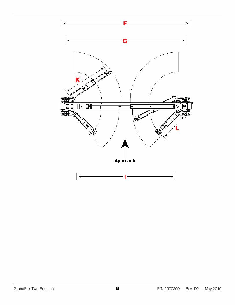
Specifications
GrandPrix Two-Post Lifts 8 P/N 5900209 — Rev. D2 — May 2019

GrandPrix Two-Post Lifts 9 P/N 5900209 — Rev. D2 — May 2019
Model GP-7LCS GP-7LC GP-7
Lifting capacity 7,000 lbs / 3,175 kg
E – Height overall 106.5" / 2,705 mm 118.5" / 3,010 mm 150" / 3,810 mm
F – Width overall 125" / 3,175 mm
G - Outside posts 119.5" / 3,035 mm
J - Floor to Trip Stop Tube 96" / 2,438 mm 108" / 2,743 140" / 3,556 mm
H – Inside posts 110" / 2,794 mm
K - Reach (front arm min) 26" / 660 mm
K - Reach (front arm max) 42" / 1,067 mm
L - Reach (rear arm min) 28" / 711 mm
L - Reach (rear arm max) 47.5" / 1,207 mm
D - Minimum pad height 4.5" / 114 mm
A – Rise 54" / 1,372 mm 64" / 1,626 mm 74" / 1,880 mm
B – Rise + pad 58" / 1,473 mm 68" / 1,727 mm 78" / 1,981 mm
C – Rise + pad + adapter 66" / 1,676 mm 76" / 1,930 mm 86.5" / 2,197 mm
I - Drive-thru width 89.5" / 2,273 mm
Standard Motor 220 VAC, 60 Hz, 1Ph
Time to full rise ~45 seconds
Maximum operating hydraulic pressure
2,940 PSI
Sound ~70 dB

GrandPrix Two-Post Lifts 10 P/N 5900209 — Rev. D2 — May 2019
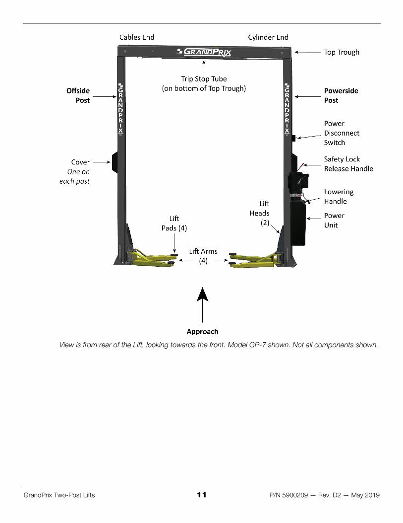
Components GP-7 Series Lift components include:
• Powerside Post: The Powerside Post holds the Power Unit, the Safety Lock Release Handle, the Lowering Handle, and the Power Disconnect Switch. The Powerside Post must go under the Cylinder end of the Top Trough.
• Offside Post: The other Post. The Offside Post goes under the Cables end of the Top Trough. • Power Unit: Provides hydraulic power to the Lift. Connects to a 220 VAC power source. Includes
the button that raises the Lift and an Hydraulic Fluid reservoir that must be filled before use. • Safety Locks: Hold the Lift Arms while they are raised. Multiple Safety Locks let you select the
best Lift Arm height for your needs. Safety Locks use gravity and intelligent engineering to hold the Lift Arms up once they are on a Safety Lock; even if the Lift loses power, the Lift Arms will stay right where they are if they were left on a Safety Lock. Only leave your GP-7 Series Lift fully lowered or engaged on a Safety Lock.
• Safety Lock Release Handle: Releases the Lift from its current Safety Lock. Used as part of the lowering process.
• Lowering Handle: Lowers a Vehicle from a raised position when used with the Safety Lock Release Handle.
• Lift Pads: Rubber pads that contact the Lifting Points of the Vehicles you raise. Also included with your Lift are three sets of extensions (short, medium, tall) that can be used with the Lift Pads.
• Lift Arms: Extendable steel arms that attach to the Lift Heads. Lift Arms hold the Lift Pads; after a Vehicle is moved into place, the Lift Arms are moved so that the rubber pads contact the Lifting points on the Vehicle. The Lift Arms are one of the components that actually holds a Vehicle up.
• Lift Heads: Sometimes called carriages. Lift Heads move up and down in the Posts. They connect to the Lift Arms, so when the Lift Heads move up, the Lift Arms (and anything on them) also move up, thus raising the Vehicle.
• Top Trough: The beam across the top of the Lift; it supports the Lift’s structure and holds the Hydraulic Cylinder and the Lifting Cables.
• Trip Stop Tube: Located on the underside of the Top Trough, the Trip Stop Tube stops upward movement of the Lift. If you are raising a Vehicle and it hits the Trip Stop Tube, the Lift immediately stops moving up.
• Power Disconnect Switch: Immediately interrupts main electrical power to the Lift. Used for electrical circuit faults, emergency situations, or when Lift is undergoing service or maintenance.
• Thermal Disconnect Switch: Overload device that makes sure the equipment shuts down if there is an overload or an overheated motor. The Lift’s motor has no thermal overload protection.
GrandPrix Two-Post Lifts 11 P/N 5900209 — Rev. D2 — May 2019
View is from rear of the Lift, looking towards the front. Model GP-7 shown. Not all components shown.

GrandPrix Two-Post Lifts 12 P/N 5900209 — Rev. D2 — May 2019
Installation Checklist Following are the steps needed to install a GP-7 Series Lift; perform them in this order.
☐ 1. Review the installation Safety Rules.
☐ 2. Plan for Electrical work.
☐ 3. Make sure you have the necessary Tools.
☐ 4. Select the installation Location.
☐ 5. Check the Clearances.
☐ 6. Review the installation Orientation.
☐ 7. Unload and Unpack the Components.
☐ 8. Put down Chalk Line Guides for the Posts.
☐ 9. Install the Post Straps.
☐ 10. Install the Powerside and Offside Posts.
☐ 11. Route the Lifting Cables.
☐ 12. Prepare the Top Trough.
☐ 13. Install the Top Trough.
☐ 14. Install the Power Unit (but do not connect it to power yet).
☐ 15. Install the Safety Assemblies and the Safety Cable.
☐ 16. Install the Trip Stop Tube.
☐ 17. Install the Microswitch and the Microswitch Cable.
☐ 18. Install the Hydraulic Lines.
☐ 19. Connect the Lifting Cables.
☐ 20. Install the Safety Covers.
☐ 21. Install the Lift Arms.
☐ 22. Contact the Electrician.
☐ 23. Connect and prepare the Power Unit.
☐ 24. Install the Power Disconnect Switch.
☐ 25. Install the Thermal Disconnect Switch.
☐ 26. Perform final Leveling of the Posts.
☐ 27. Torque the Anchor Bolts.
☐ 27. Lubricate the Lift.
☐ 29. Bleed the Hydraulic Cylinder.
☐ 30. Review the Final Checklist.

GrandPrix Two-Post Lifts 13 P/N 5900209 — Rev. D2 — May 2019
Installation The installation process includes multiple steps. Perform them in the order listed.
Safety Rules When installing the Lift, your safety depends on proper training and thoughtful operation.
⚠ WARNING Do not install this equipment unless you have automotive Lift installation training. Always use proper Lifting tools, such as a forklift or crane, to raise heavy components. Do not install this equipment without reading and understanding this manual and the safety labels on the unit.
Only fully trained personnel should be involved in installing this equipment. Pay attention at all times. Use appropriate tools and Lifting equipment, when needed. Stay clear of moving parts.
⚠ WARNING You must wear appropriate protective equipment: leather gloves, non-skid steel-toed work boots, eye protection, back belts, and hearing protection.
Electrical Work You will need to have a licensed, certified Electrician available at some point during the installation. All of the tasks listed below must be performed by an Electrician.
⚠ DANGER All wiring must be performed by a licensed, certified Electrician. If someone who is not a certified Electrician attempts these tasks, they could damage the Lift or be electrocuted, resulting in serious injury or even death.
The Electrician needs to:
• Wire the 220 VAC power source to the Power Unit. This is generally done near the end of the installation process; do not connect the Power Unit at the same time as you install it.
• Wire the Microswitch to the Power Unit. This is generally done at the same time as the Electrician wires the power source to the Power Unit, as the Microswitch wiring goes between the incoming power source and the Electrical Box on the Power Unit.
• Install a Power Disconnect Switch. A Power Disconnect Switch ensures that the equipment shuts down in the event of an electrical circuit fault or emergency situation. Refer to Install a Power Disconnect Switch for more information.
• Install a Thermal Disconnect Switch. A Thermal Disconnect Switch ensures that the equipment shuts down in the event of an overload or an overheated motor. Refer to Install a Thermal Disconnect Switch for more information.
The Electrician is responsible for providing:
• an appropriate power cable and plug for connecting to the power source
(wiring to connect the Microswitch to the Power Unit is included)
• a Power Disconnect Switch • a Thermal Disconnect Switch
Additional information is supplied in the sections describing these tasks.

GrandPrix Two-Post Lifts 14 P/N 5900209 — Rev. D2 — May 2019
Tools You may need some or all of the following tools:
• Rotary hammer drill (or similar)
• ¾ inch carbide bit (conforming to ANSI B212.15-1994)
• Hammer
• Four-foot level
• Open-end wrench set, SAE and metric
• Socket and ratchet set, SAE and metric
• Hex key wrench set
• Crescent and pipe wrenches
• Torque wrench
• Crow bar
• Chalk line
• Medium-sized flat screwdriver
• Tape measure, 25 feet or above
• Needle-nose pliers
• Heavy-duty rolling dolly
• Forklift or crane
• Two 12-foot ladders
• Two saw horses
Selecting a Location When selecting the location for your GP-7 Series Lift, consider:
• Architectural plans. Consult the architectural plans for your desired installation location. Make sure there are no contradictions between what you want to do and what the plans show.
• Available space. Make sure there is enough space for the Lift; front, back, sides, and above. Refer to Specifications for exact measurements.
• Overhead obstructions. Check for overhead obstructions such as building supports, heaters, lights, electrical lines, low ceilings, and so on.
• Power. You need a 220 VAC power source available for the Lift’s Power Unit. • Outdoor installations. GrandPrix Lifts are approved for indoor installation and use only.
Outdoor installation is prohibited. • Floor. Only install the Lift on a flat, Concrete floor; do not install on asphalt or any other surface.
The surface must be level; do not install if the surface has more than three degrees of slope.
⚠ WARNING Installing your Lift on a surface with more than three degrees of slope could lead to injury or even death. Only install GrandPrix Lifts on a level floor (defined as no more than 3/8 of an inch difference over the installation area). If your floor is not level, consider making the floor level or using a different location.
GrandPrix Two-Post Lifts 15 P/N 5900209 — Rev. D2 — May 2019
• Concrete specifications. Do not install the Lift on cracked or defective concrete. Anchor Bolts must be at least 6 inches from cracks, expansion seams, or other inconsistencies in the Concrete. Make sure the concrete is at least 4.25 inches thick, 3,000 PSI, and cured for a minimum of 28 days.
⚠ CAUTION BendPak Lifts are supplied with installation instructions and concrete anchors that meet the criteria set by the American National Standard “Automotive Lifts – Safety Requirements for Construction, Testing, and Validation”, ANSI/ALI ALCTV-2011. You are responsible for any special regional structural and/or seismic anchoring requirements specified by any other agencies and/or codes such as the Uniform Building Code (UBC) and/or International Building Code (IBC).
Check your floor for the possibility of it being a post tension slab. In this case, contact the building architect before drilling. Using ground penetrating radar may help you find the tensioned steel.
⚠ WARNING Cutting through a tensioned cable can result in injury or death. Do not drill into a post tension slab unless the building architect confirms you are not going to hit tensioned steel or you have located it using ground penetrating radar. If colored sheath comes up during drilling, stop drilling immediately.
Anchor Bolt specifications are:
• Length: 6.25 inches • Diameter: ¾ inch • Effective embedment depth: 3.25 inches, minimum • Anchor torque: 110 – 150 foot pounds
⚠ WARNING Use the ALI-certified Anchor Bolts that came with your GP-7 Series Lift. If you use components from a different source, you void your warranty and compromise the safety of everyone who installs or uses the Lift.

GrandPrix Two-Post Lifts 16 P/N 5900209 — Rev. D2 — May 2019
Clearances
Installation Orientation To determine the front of your Lift, drive a Vehicle in straight (do not back it in) and stop. The front of the Lift is where the front of the Vehicle is.
The approach is the direction you drive a Vehicle onto the Lift. Generally the approach is from the rear of the Lift towards the front of the Lift.
The orientation of the procedures and drawings in this manual is looking at the Lift from the rear, towards the front, unless specified otherwise. This is the same orientation as shown in the image in the Components section and in the drawing below.
This means that:
• The Powerside Post (which holds the Lowering Handle and the Power Unit) is on the right, the Offside Post is on the left.
• The Hydraulic Cylinder end of the Top Trough is on the right, above the Power Unit.

GrandPrix Two-Post Lifts 17 P/N 5900209 — Rev. D2 — May 2019
• The two angled arms are at the ‘front’ of the Lift. • The two straight arms are at the ‘rear’ of the Lift.
The following drawing shows how to orient the Powerside and the Offside Posts.
Not necessarily to scale. Not all components shown.
To identify the Powerside Post and the Offside Post, look at the tops of the Lift Heads in each of the Posts:
• Powerside Post. The Lift Head with widely spaced holes is the Powerside Post. The Powerside Post must go under the Cylinder End of the Top Trough.
• Offside Post. The Lift Head with the narrowly spaced holes must be the Offside Post. The Offside Post must go under the Cable End of the Top Trough.
Important: You must orient the Powerside and Offside Posts this way. If they are set up wrong, the Lift will not work correctly.

GrandPrix Two-Post Lifts 18 P/N 5900209 — Rev. D2 — May 2019
Unloading and Unpacking Unload the Lift components as close to the installation location as possible.
Once the components are unloaded, they are your responsibility to move around. The Lift includes a number of heavy pieces, so the closer you unload them to the installation location, the better off you will be.
⚠ WARNING Some Lift components are very heavy; if handled incorrectly, they can damage materials like tile, sandstone, and brick. Try to handle the Lift components just twice: once when delivered and once when moved into position. You must have a forklift or crane to move some of the Lift components into position. Use care when moving them around.
Putting in Chalk Line Guides Based on the specifications for your Lift, create Chalk Line Guides on the ground for the two posts prior to moving them into position.
Use the Width Overall value in Specifications for your Lift model to determine where to place the Chalk Line Guides. The Width Overall value is defined as the distance from the back of one base plate to the back of the other base plate.
To add Chalk Line Guides:
1. Decide where you want to locate the Lift.
2. Create an alignment chalk line at the desired location.
The alignment chalk line must be longer than the Width Overall setting for your Lift model.
3. Create two perpendicular chalk lines at 90° angles to the alignment chalk lines.
The two perpendicular chalk lines must be x distance from each other, where x is the Width Overall setting for your Lift model.
4. When you move the posts into position, put the corners of the base plates into the corners created by the Chalk Line Guides.

GrandPrix Two-Post Lifts 19 P/N 5900209 — Rev. D2 — May 2019
Installing the Post Straps You may want to install the Post Straps on their Posts prior to standing them up. It is not required, but if you install them after standing up the Posts, you will need a ladder to reach them.
Important: The Post Strap with the welded plate goes on the Powerside Post. The Post Strap without the welded plate goes on the Offside Post.
To install the Post Straps:
1. Bolt the Post Strap with the welded plate to the Powerside Post.
2. Bolt the other Post Strap (no welded plate) to the Offside Post.

GrandPrix Two-Post Lifts 20 P/N 5900209 — Rev. D2 — May 2019
Installing the Posts We strongly recommend having multiple people working together to install the Posts.
Concrete specifications are:
• Depth: 4.25 inches thick • PSI: 3,000 PSI, minimum • Cured: 28 days, minimum
Anchor Bolt specifications are:
• Length: 6.25 inches • Diameter: ¾ inch • Effective embedment: 3.25 inches, minimum • Anchor torque: 110 – 150 foot pounds
⚠ WARNING Your Concrete and Anchor Bolts must meet these specifications. Only install your Lift on a Concrete surface. If you install a Lift on asphalt or any other surface, or your Concrete or Anchor bolts do not meet these specifications, it could lead to product damage, Vehicle damage, personal injury, or even loss of life.
BendPak Lifts are supplied with installation instructions and concrete fasteners meeting the criteria as prescribed by the American National Standard “Automotive Lifts – Safety Requirements for Construction, Testing, and Validation” ANSI/ALI ALCTV-2006.
⚠ WARNING Use only the ALI-certified Anchor Bolts that came with your GP-7 Series Lift. If you use components from a different source, you void your warranty and compromise the safety of everyone who installs or uses the Lift.
Lift buyers are responsible for conforming to all regional, structural, and seismic anchoring requirements specified by any other agencies and/or codes, such as the Uniform Building Code and/or International Building Code.
Tip Consider not torqueing the Anchor Bolts into position quite yet. Two reasons: installing the Top Trough and doing final leveling may be easier if there is a little play in the Posts.
To install the posts:
1. Using a forklift, crane, or heavy-duty rolling dolly, move the Posts to the Chalk Line Guides you created earlier.
2. Stand up each Post, one at a time, and move the appropriate corners into the corners created by the Chalk Line Guides.
3. Double check your measurements against the Specifications for your GP-7 Series Lift model:
Distance from back of one base plate to back of other base plate: Width Overall value Distance from inside of one Post to inside of other Post: Inside Posts value

GrandPrix Two-Post Lifts 21 P/N 5900209 — Rev. D2 — May 2019
4. Using the Base Plates as guides, drill the holes for the Anchor Bolts.
Go in straight; do not let the drill wobble.
Use a carbide bit (conforming to ANSI B212.15-1994).
The diameter of the drill bit must be the same as the diameter of the Anchor Bolt. So if you are using a ¾ inch diameter Anchor Bolt, for example, use a ¾ inch diameter drill bit.
5. Vacuum each hole clean.
BendPak recommends using a vacuum to get the hole very clean. You can also use a wire brush, hand pump, or compressed air; just make sure to thoroughly clean each hole.
Do not ream the hole. Do not make the hole any wider than the drill bit made it.
Important: The holding strength of an Anchor Bolt is partially based on the how cleanly the Expansion Sleeve presses against the Concrete. If the hole is dirty, the Expansion Sleeve does not press as cleanly, which means less holding strength. If the hole is too wide, the Expansion Sleeve does not press against the Concrete with as much force, again resulting in less holding strength.
6. Make sure the Washer and Nut are in place, then insert the Anchor Bolt into the hole.
The Expansion Sleeve of the Anchor Bolt may prevent the Anchor Bolt from passing through the hole in the Base Plate; this is normal. Use a hammer or mallet to get the Expansion Sleeve through the Base Plate and into the hole.
Even using a hammer or mallet, the Anchor Bolt should only go into the hole part of the way; this is normal. If the Anchor Bolt goes all the way in with little or no resistance, the hole is too wide.

GrandPrix Two-Post Lifts 22 P/N 5900209 — Rev. D2 — May 2019
Once past the hole in the Base Plate, the Anchor Bolt eventually stops going down into the hole as the Expansion Sleeve contacts the sides of the hole; this is normal.
7. Hammer or mallet the Wedge Anchor the rest of the way down into the hole.
Stop when the Washer is snug against the Base Plate.
8. Plumb each Post; install any needed Shims or the optional Adapter Trays (which let you stack the provided adapters conveniently near the Lift Arms).
9. Do not torque the Anchor Bolts at this point.
Installing the Top Trough and doing final leveling (both of which are done later in the installation process) are both easier if there is a little bit of play in the Posts.
If you torque the Anchor Bolts now, there will not be any play in the Posts, making it more difficult to install the Top Trough and do final leveling.

GrandPrix Two-Post Lifts 23 P/N 5900209 — Rev. D2 — May 2019
About the Lifting Cables
⚠ CAUTION We strongly recommend wearing gloves while handling the Lifting Cables.
GP-7 Series Lifts use four Lifting Cables: two Long Cables and two Short Cables. The following drawing shows the two different types of ends on these cables. Note that the ends are exaggerated in this drawing to make it easier to see the two types of ends.
The Button end of all four cables start at the same place (at the Tie Plate, in the Top Trough, shown in the upper left corner in the drawing below).
The Threaded end of the two Short Cables end at the Offside Lift Head. The Threaded end of the two Long Cables end at the Powerside Lift Head.
The following drawing shows the routing for the Lifting Cables. The Top Trough and both posts have been removed so you can see just the Lifting Cables and associated components.
Both short cables are exactly the same; it does not matter what order you install them in. Both long cables are also exactly the same.

GrandPrix Two-Post Lifts 24 P/N 5900209 — Rev. D2 — May 2019
The following drawing is a top view of the components of the Top Trough. Not every component is shown, just the components relevant to installing the Lift. The Offside Post is on the left, the Powerside Post is on the right.
Preparing the Top Trough The Top Trough goes between the two posts at the top of the Lift.
To prepare the Top Trough, you need to:
• Route the Lifting cables. • Route the safety cables. • Connect the hydraulic cables (but not the hydraulic lines).
Tip We strongly recommend raising the Top Trough off the ground when performing these preparation tasks; a saw horse works great for this, for example.
Routing the Lifting Cables
The Lifting cables move the Lift Heads and Lift Arms up and down.
To route the Lifting cables:
1. Make sure you have two Long Cables and two Short Cables.
All cables have ID tags showing their lengths.
2. Extend the Cylinder Rod until the Pullblock sheave pin lines up with the Access Hole in the Top Trough.
This can be done by carefully pulling the Cylinder Rod by hand or carefully using an air gun (remove both plugs, insert air gun in port furthest from the Cylinder Rod, push air in).
⚠ CAUTION Be careful not to damage the Cylinder Rod when extending it. Do not exceed 50 PSI if using an air gun. If Cylinder Rod is not extending, stop and use a cable puller or other pulling device. Keep hands clear of pinch points.

GrandPrix Two-Post Lifts 25 P/N 5900209 — Rev. D2 — May 2019
This drawing is looking down on the Top Trough from above.
Tip BendPak recommends installing the two Short Cables (which go on the inner sheaves) first, then proceed to the two longer cables (which go on the outer sheaves). You can do it any way you want, but these instructions go in that order.
3. Put the Button End of first Short Cable into position at the Tie Plate.
The following drawing is a side view of how a Short Cable gets routed over the sheaves.
4. Route the Short Cable under the bottom of the Cylinder side sheave and then over the top of it, over the top of the Offside end sheave, and down through the hole in the bottom of the Top Trough.
5. Do the same thing for the second short cable.
Make sure to put the Button End of the second Short Cable on the other side of the Tie Plate from the Button End of the first Short Cable.
6. Put the Button End of the first Long Cable into position at the Tie Plate, on the outside of either of the two Short Cables (it does not matter which one you do first).

GrandPrix Two-Post Lifts 26 P/N 5900209 — Rev. D2 — May 2019
The following drawing is a side view of how the Long Cables get routed over the sheaves on the Offside end of the Top Trough.
7. Once the Button End is in place, route each Long Cable like this:
• Under the bottom of the Cylinder side sheave and then over the top of it.
• Over the top of the Offside end sheave and then under the bottom of it.
• Past the Cylinder side sheave (without touching it), towards the two-groove sheave on the Powerside end.
• Over the two-groove sheave on the Powerside end and then down into the appropriate hole in the bottom of the Top Trough.
The following drawing is a side view of how the Long Cables get routed over the two-groove sheave and down into the hole on the Powerside end of the Top Trough.
Make sure the all cables sit in the grooves and not on either edge of the sheave assembly.

GrandPrix Two-Post Lifts 27 P/N 5900209 — Rev. D2 — May 2019
8. Secure the cables with the top of the Tie Plate using a flat head and hex head bolts.
The following drawing shows how the Button ends and cables should appear just after you secure the top of the Tie Plate into position.
Important: Make sure the cables are carefully aligned in their sheaves; you want to avoid as much contact as possible between the cable and the sheaves while the Lift is in motion. This makes the Lift move more smoothly and extends the life of the cables and the sheaves.
9. The ends of the four cables will be hanging over the ends of the Top Trough.
⚠ CAUTION Do not step on or trip over the four Lifting cables while the Top Trough remains near the ground. They are a hazard until the Top Trough is put into position.
Routing the Safety Cable
The Safety Cable connects to the safety mechanism on the Offside Post, goes over the Safety Sheave in the Offside end of the Top Trough, travels over the Lifting Cables in the Top Trough, goes over the Safety Sheave in the Powerside end of the Top Trough, and then goes down to the safety mechanism on the Powerside Post and eventually to the Safety Lock Release Handle.
After being fully set up, the Safety Cable and the Safety Lock Release Handle are used to release the safety locks, allowing the Lift to be lowered.
One end of the Safety Cable has a loop on it, the other does not. The loop end must be installed on the Offside Post side.
To route the Safety Cable:
1. Locate the Safety Cable.
The Safety Cable is a long, thin steel cable with a loop on one end; the other end does not have a loop.
The loop end of the Safety Cable connects to the safety mechanism on the Offside Post; the ends are not interchangeable.
Make sure to orient the Safety Cable so that the loop end stays on the Offside Post side of the Lift.
2. Route the cable through the small notch in the bottom of the Top Trough, around the Offside Safety Sheave, across the Top Trough above the other components, around the Powerside

GrandPrix Two-Post Lifts 28 P/N 5900209 — Rev. D2 — May 2019
Safety Sheave, down through the small notch in the bottom of the Top Trough, and down to the Powerside Safety.
3. Leave the two ends of the Safety Cable hanging over the ends of the Top Trough.
They will remain this way until the Top Trough is put into place.
⚠ CAUTION Do not step on or trip over the Safety Cable while the Top Trough remains near the ground. It is a hazard until the Top Trough is put into position.
Connecting the Hydraulic Cables
The Hydraulic Cables connect to ports on the Hydraulic Cylinder on one end and to the Hydraulic Lines on the other end. Together, the Hydraulic Cables and Hydraulic Lines move hydraulic power to and from the Hydraulic Cylinder.
The two Hydraulic Cables are:
• Long Hydraulic Cable. Connects to the Hydraulic In port. • Short Hydraulic Cable. Connects to the Hydraulic Return port.

GrandPrix Two-Post Lifts 29 P/N 5900209 — Rev. D2 — May 2019
To connect the Hydraulic Cables:
1. Remove the shipping plugs from the Hydraulic In and Hydraulic Return ports on the Hydraulic Cylinder.
2. Install a 90° Cylinder Fitting in each of those ports.
Leave the fittings facing towards the Powerside Post.
3. Connect the Long Hydraulic Cable to the Hydraulic In fitting; route the cable towards the Powerside.
4. Connect the Short Hydraulic Cable to the Hydraulic Return fitting; route the cable towards the Powerside.
⚠ CAUTION Do not pull on the Hydraulic Cables while the Top Trough remains near the ground. They are going to stay where they are until the Top Trough is put into position.
Installing the Top Trough The Top Trough holds the Hydraulic Cylinder and the Lifting Cables. It also supports the Trip Stop Tube underneath it.
⚠ CAUTION Watch out for the already-installed cabling. Make sure they do not get in the way as you move the Top Trough into position.
Important: The Top Trough must be installed in a specific orientation: the end with the Hydraulic Cylinder must go over the Powerside Post; the end with the sheave assemblies must go over the Offside Post.
To install the Top Trough:
1. Using a Lifting device, raise the Top Trough into position on top of the two posts.
Check the orientation of the Top Trough: the end with the Hydraulic Cylinder must go over the Powerside Post; the end with the four-groove sheave assemblies must go over the Offside Post.
2. Align the holes on the top of the Powerside Post with the holes on the bottom of the Top Trough, then connect the two using the supplied 10 mm hex bolts, nuts, and the two pipe straps.

GrandPrix Two-Post Lifts 30 P/N 5900209 — Rev. D2 — May 2019
The pipe straps will be used later to hold in place the Hydraulic Lines that run from the Power Unit to the Hydraulic Cylinder.
3. Align the holes on the top of the Offside Post with the holes on the bottom of the Top Trough, then connect the two using the supplied 10 mm hex bolts, washers, and nuts.
The Offside Post connection to the Top Trough uses washers, not pipe straps.
Installing the Power Unit This section describes how to install the Power Unit for your Lift.
Important: Do not connect the Power Unit to the hydraulic system or to the power source at this point.
The standard Power Unit for your Lift is 208-240 VAC, 50/60 Hz, 1 phase. Note that the motor is not thermally protected.
The Power Unit must be installed on the Powerside Post.
⚠ DANGER All wiring must be performed by a licensed, certified Electrician. Do not perform any maintenance or installation on the Lift without first making sure that main electrical power has been disconnected from the Lift and cannot be re-energized until all procedures are complete.
Important electrical information:
• Improper electrical installation can damage the Power Unit motor; this damage is not covered under warranty.
• Use a separate circuit breaker for each Power Unit.
• Protect each circuit with a time-delay fuse or circuit breaker. For a 220 VAC, 1 phase circuit, use a 25 amp or greater fuse.
The Power Unit’s hydraulic fluid reservoir must be filled with Hydraulic Fluid or automatic transmission fluid before you begin operation. When you receive it, the oil reservoir is empty. The Power Unit will not work correctly until it is filled with approved fluids.
Approved fluids are any general purpose ISO-32, ISO-46, or ISO-68 hydraulic oil or approved automatic transmission fluids such as Dexron III, Dexron VI, Mercon V, Mercon LV, or any synthetic multi-Vehicle automatic transmission fluid.
⚠ WARNING Do not run your Power Unit without hydraulic fluid; you will damage it. Keep the Power Unit dry; damage to the Power Unit caused by water, detergents, acid, and other liquids is not covered by the warranty.
To install the Power Unit:
1. If the Lift Head (also called the carriage) is blocking access on the inside of the Powerside Post to the holes used to attach the Power Unit, raise it out of the way.
⚠ WARNING BendPak recommends using a Lifting device to raise the Lift Head; a forklift, for example. Lift Heads are heavy. If you attempt to raise a Lift Head yourself, you could injure yourself and potentially damage the product.
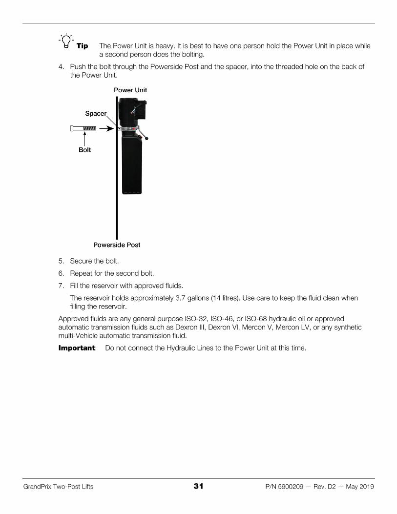
2. Find the two supplied M10 x 1.25 x 40 mm hex bolts and the two white plastic spacers.
3. Move the Power Unit into place: the holes in the back of the Power Unit (in the silver strip on the Power Unit) must line up with the holes in the Powerside Post.
GrandPrix Two-Post Lifts 31 P/N 5900209 — Rev. D2 — May 2019
Tip The Power Unit is heavy. It is best to have one person hold the Power Unit in place while a second person does the bolting.
4. Push the bolt through the Powerside Post and the spacer, into the threaded hole on the back of the Power Unit.
5. Secure the bolt.
6. Repeat for the second bolt.
7. Fill the reservoir with approved fluids.
The reservoir holds approximately 3.7 gallons (14 litres). Use care to keep the fluid clean when filling the reservoir.
Approved fluids are any general purpose ISO-32, ISO-46, or ISO-68 hydraulic oil or approved automatic transmission fluids such as Dexron III, Dexron VI, Mercon V, Mercon LV, or any synthetic multi-Vehicle automatic transmission fluid.
Important: Do not connect the Hydraulic Lines to the Power Unit at this time.

GrandPrix Two-Post Lifts 32 P/N 5900209 — Rev. D2 — May 2019
Installing the Safety Assemblies and the Safety Cable Each GP-7 Lift has two Safety Assemblies: one on the Powerside Post (above the Power Unit) and the other on the Offside Post.
The two Safety Assemblies work together to take the load off the Hydraulic Cylinder and the Lifting cables once the Lift has reached the desired working height. The Safety Assemblies need to be disengaged at the same time so that the Lift Arms lower together. In order to do this, the two Safety Assemblies have to be connected to each other via the Safety Cable, which was routed through the Top Trough earlier in the installation.
The following drawing shows the components of the Powerside Safety Assembly.
The following drawing shows the components of the Offside Safety Assembly.

GrandPrix Two-Post Lifts 33 P/N 5900209 — Rev. D2 — May 2019
To install the two Safety Assemblies:
1. For the Powerside Post, locate the Safety Assembly with the Safety Lock Release Handle, a safety clevis pin, two springs, and one cotter pin (sometimes called a hairpin).
2. Put one of the springs next to the head of the safety clevis pin, then insert the safety clevis pin, from the left, through the hole in the left welded plate, then through the Safety Assembly, and then through the right welded plate.
3. Put the second spring on the right end of the safety clevis pin, then install the cotter pin.
The following drawing shows the components involved in installing a Safety Assembly. Note that the procedures for the Powerside Post and the Offside Post are quite similar. The difference is that some of the components on the Powerside Safety Assembly are slightly different from the components on the Offside Safety Assembly.
4. For the Offside Post, locate the safety assembly without the Safety Lock Release Handle, a safety clevis pin, two springs, and one cotter pin (sometimes called a hairpin).
5. Put one of the springs next to the head of the safety clevis pin, then insert the safety clevis pin, from the left, through the hole in the left welded plate, then through the Safety Assembly, and then through the right welded plate.
6. Put the second spring on the right end of the safety clevis pin, then install the cotter pin.

GrandPrix Two-Post Lifts 34 P/N 5900209 — Rev. D2 — May 2019
The Safety Cable connects the two Safety Assemblies together.
Note: The Safety Cable should have been installed earlier. The following procedure describes how to hook up the Safety Cable on the Offside Post and on the Powerside Post.
To connect the Safety Cable:
1. On the Offside Post, bring the loop end of the Safety Cable down through the inside of the Offside Post.
2. Pull the Safety Cable out to the front of the Offside Post underneath the sheave under the Short Welded Pin; make sure the Safety Cable is sitting correctly in the sheave.
3. Route it over the Short Welded Pin (you will have to remove the Rotor Clip first) and then put the loop over the right end of the Welded Pin (above the Safety Clevis Pin); move the loop next to the Safety Assembly, inside the Spring.
You will need to move the top of the Spring out of the way to slide the loop end of the Safety Cable over the right end of the Welded Pin.
Make sure the top of the Spring is sitting against the Welded Pin, effectively holding the loop end of the Safety Cable in place.
4. Replace the Rotor Clip.
The following photo shows how the Safety Cable should look on the Offside Post.
5. On the Powerside Post, screw two nuts onto the threaded end of the Welded Pin with Threads. Make sure that one is on each side of the hole in the Welded Pin with Threads.
6. Bring the straight end of the Safety Cable down through the inside of the Powerside Post.

GrandPrix Two-Post Lifts 35 P/N 5900209 — Rev. D2 — May 2019
7. Pull the straight end of the Safety Cable out to the front of the Powerside Post underneath the Safety Sheave; make sure the Safety Cable is seated correctly in the Safety Sheave.
8. Put the straight end of the Safety Cable over the front of the Welded Pin and into the hole in the Welded Pin with Threads, between the two nuts.
9. Pull any slack out of the Safety Cable, then tighten the nuts.
When tightening the nuts, keep tension on the Safety Cable and keep the Safety Cable centered between the two nuts.
The following photo shows how the Safety Cable should look on the Powerside Post.
10. Operate the Safety Lock Release Handle, checking for proper operation of both Safety Assemblies.
⚠ DANGER Make sure that both the Powerside and the Offside Safety Assemblies engage properly before using the Lift.

GrandPrix Two-Post Lifts 36 P/N 5900209 — Rev. D2 — May 2019
Installing the Trip Stop Tube The Trip Stop Tube is installed on the underside of the Top Trough.
The Trip-Stop Tube stops upward movement of the Lift; if you are raising a Vehicle and it hits the Trip-Stop Tube, the Lift immediately stops moving up.
To install the Trip Stop Tube:
1. On the Powerside, slide the Trip Stop Tube through the welded Post Strap, then fasten the threaded end of the Microswitch Cable through the hole in the tube.
2. Route the loop end of the Microswitch Cable down the inside of the Powerside Post.
3. On the Offside, secure the other end of the Trip Stop Tube to the underside of the Top Trough using a 50 mm hex bolt, washer, and nut.
The bolt must be inserted from inside the Top Trough.

GrandPrix Two-Post Lifts 37 P/N 5900209 — Rev. D2 — May 2019
Installing the Microswitch and the Microswitch Cable The Microswitch is the mechanism by which the Trip Stop Tube stops the Lift, if necessary.
To install the Microswitch Cable and the Microswitch:
1. Install the Microswitch Assembly on the right side of the Powerside Safety Assembly using two button head screws.
2. Find the loop end of the Microswitch Cable on the inside of the Powerside Post, then push it through to the outside of the Powerside Post just under the Microswitch Sheave.
3. Make sure the Microswitch Cable is correctly seated in the Microswitch Sheave.
4. Put the loop end of the Microswitch Cable over the trigger on the front of the Microswitch.
5. Have your Electrician wire the cable at the bottom of the Microswitch to your Power Unit.
Make sure the Power Unit is disconnected from the power source. Remove the cover on the Power Unit, then connect the two cables coming from the Microswitch between the switch and the contactor. Reinstall the Power Unit cover.
⚠ DANGER All wiring must be performed by licensed, certified electricians. Do not perform any maintenance or installation on the Lift without first making sure that main electrical power has been disconnected from the Lift and cannot be re-energized until all procedures are complete.

GrandPrix Two-Post Lifts 38 P/N 5900209 — Rev. D2 — May 2019
Installing Hydraulic Lines The two metal Hydraulic Lines run along the outside of the Powerside Post. They connect to ports on the Power Unit on one end and to the flexible Hydraulic Hoses (in the Top Trough) on the other end.
The two flexible Hydraulic Hoses were connected to the Hydraulic Cylinder earlier in the installation.
Note: The two metal Hydraulic Lines look similar, but they are not the same. Make sure you orient them correctly. If you get them backwards, they will not connect correctly to the Power Unit.
To install the two metal Hydraulic Lines:
1. Orient the two Hydraulic Lines correctly on the side of the Powerside Post (see drawing below).
At the bottom, one of the two comes out further from the Powerside Post (so that it can reach the proper port on the Power Unit); that metal Hydraulic Line goes on the right side. The drawing below shows the correct orientation of the two metal Hydraulic Lines.
The Flare Fittings at the top of the two metal Hydraulic Lines go under the metal strap at the top of the Top Trough, near the Safety Cable. Make sure the two metal Hydraulic Lines do not interfere with the Safety Cable.

GrandPrix Two-Post Lifts 39 P/N 5900209 — Rev. D2 — May 2019
2. Remove the plastic plugs from the appropriate ports on the Power Unit: the Hydraulic Return port (left rear connector) and the Hydraulic Power Out port (right front connector).
3. For the Hydraulic Return port, install a 90° hydraulic fitting. Connect that 90° fitting to the fitting on the bottom of the Hydraulic Return Line.
4. For the Hydraulic Power Out port, connect a 90° ORB fitting. Connect that 90° ORB fitting to the fitting on the bottom of the Hydraulic Power Line.
Use thread seal tape on the NPT threads only.
5. In the Top Trough, install a straight JIC fitting to the to the end of each Hydraulic Hose, then install Flare Fittings to the end of each Hydraulic Line.
6. Connect the Hydraulic Hoses to the corresponding Hydraulic Lines.
7. When the two metal Hydraulic Lines are connected to the Power Unit and the flexible Hydraulic Hoses, fix them in place using the Pipe Straps on the side of the Powerside Post.

GrandPrix Two-Post Lifts 40 P/N 5900209 — Rev. D2 — May 2019
Connecting the Lifting Cables The threaded ends of the Lifting Cables, which were installed in the Top Trough earlier in the installation, connect to the Lift Heads inside the Offside and Powerside Posts; two Lifting Cables per Post.
To connect the Lifting Cables:
1. Inside the Powerside Post, insert the threaded ends of the two Lifting Cables through the holes adjacent to the Retainer on the top of the Lift Heads.
The holes on the Powerside Post (shown below) are widely spaced, compared to the holes on the Offside Post.
2. Place one M18 washer and M18 Nyloc nut on the threaded end; tighten the nuts until taut, making sure both cables have equal tension.

GrandPrix Two-Post Lifts 41 P/N 5900209 — Rev. D2 — May 2019
3. For the Offside Post, repeat the same process, except the holes adjacent to the Retainer on the top of the Lift Heads are narrowly spaced, compared to the holes on the Powerside Post.
4. Place one M18 washer and M18 Nyloc nut on the threaded cable end; tighten the nuts until taut, making sure both cables have equal tension.

GrandPrix Two-Post Lifts 42 P/N 5900209 — Rev. D2 — May 2019
Installing the Safety Covers There are two Safety Covers, one for each Safety Assembly. Refer to Installing the Safety Assemblies and the Safety Cable for more information about Safety Assemblies.
The Safety Covers are not interchangeable:
• The Offside Post Safety Cover can be installed in either orientation. • The Powerside Post Safety Cover can only be installed in one orientation: there is a slot on the
front for the Safety Lock Release Handle and a hole in the bottom for the Microswitch Cable.
Both Safety Covers connect to their Posts via holes in the upper left and lower right corners.
To install the Safety Covers:
1. On the Offside Post, make sure the cover screws are installed in each block.
There must be enough space between the block and the screw to fit the Safety Cover.
2. Put the Safety Cover into position, then tighten both cover screws.
3. On the Powerside Post, make sure the cover screws are installed in each block.
4. Put the Safety Cover into position.
Make sure the Safety Lock Release Handle comes through the slot on the front and that the Microswitch Cable comes through the hole on the bottom.
5. Tighten both cover screws.
Installing the Lift Arms Lift Arms are what actually raise Vehicles off the ground.
Your Lift has four arms:
• Two Straight Arms: install them at the rear of the Lift. • Two Angled Arms: install them at the front of the Lift.
To install the Lift arms:
1. Raise a Lift Head two to three inches off the ground.
2. Move a Lift Arm into place in the Lift Head.
3. Install a Lift Head Pin through the Lift Head and the Lift Arm, then push a Snap Ring into its grooves on the bottom of the Lift Head Pin.

GrandPrix Two-Post Lifts 43 P/N 5900209 — Rev. D2 — May 2019
Make sure an Angled Arm Spacer is in place on top of each Angled Lift Arm; they are not necessary for Straight Lift Arms.
4. Repeat Steps 2 and 3 for each of the other Lift Arms.
⚠ DANGER The gears must be positioned and adjusted properly. Confirm proper gear engagement prior to operation of the Lift. Periodic inspection and adjustment is also required. Failure to properly inspect and adjust the arm restraint gears on all four arms can result in damage to the Vehicle, injury, or even death.
5. Install the Arm Gear Ring bolts and adjust the Arm Gear Rings so that the teeth on the gear ring mesh fully and smoothly with the teeth on the Arm Restraint Gear.
Important: Arm Gear Rings have a Left or Right orientation, based on looking at the Post from the inside of the Lift, as shown above. You must correctly orient the arms.
GrandPrix Two-Post Lifts 44 P/N 5900209 — Rev. D2 — May 2019
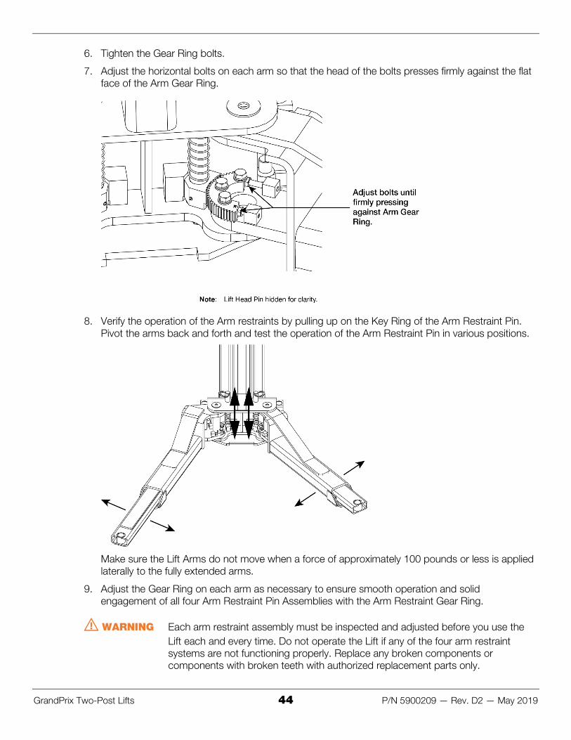
6. Tighten the Gear Ring bolts.
7. Adjust the horizontal bolts on each arm so that the head of the bolts presses firmly against the flat face of the Arm Gear Ring.
8. Verify the operation of the Arm restraints by pulling up on the Key Ring of the Arm Restraint Pin. Pivot the arms back and forth and test the operation of the Arm Restraint Pin in various positions.
Make sure the Lift Arms do not move when a force of approximately 100 pounds or less is applied laterally to the fully extended arms.
9. Adjust the Gear Ring on each arm as necessary to ensure smooth operation and solid engagement of all four Arm Restraint Pin Assemblies with the Arm Restraint Gear Ring.
⚠ WARNING Each arm restraint assembly must be inspected and adjusted before you use the Lift each and every time. Do not operate the Lift if any of the four arm restraint systems are not functioning properly. Replace any broken components or components with broken teeth with authorized replacement parts only.

GrandPrix Two-Post Lifts 45 P/N 5900209 — Rev. D2 — May 2019
Contact the Electrician As mentioned previously, there are certain installation tasks that require a certified Electrician.
⚠ DANGER All wiring must be performed by a licensed, certified Electrician. If someone who is not a certified Electrician attempts these tasks, they could damage the Lift or be electrocuted, resulting in serious injury or even death.
The Electrician needs to:
• Attach a Power Cable with an appropriate plug. The Power Unit needs to connect to an appropriate power source; it comes with a pigtail coming out of the Electrical Box, but without a longer power cable or a plug attached. The Electrician needs to remove the pigtail and then connect a power cable with a plug that is appropriate for your location (220 VAC plugs are different in different parts of the world). This power cable and plug is not provided with the Lift.
• Wire the Microswitch. This is generally done at the same time as the Electrician wires the power source to the Power Unit, as the Microswitch wiring goes between the incoming power source and the Electrical Box on the Power Unit. The Microswitch wiring is provided with the Lift.
• Install a Power Disconnect Switch. Ensures you can quickly and completely interrupt electrical power to the Lift in the event of an electrical circuit fault, emergency situation, or when equipment is undergoing service or maintenance. You must put it within sight and easy reach of the Lift operator. Refer to Install a Power Disconnect Switch for more information.
• Install a Thermal Disconnect Switch. Ensures the equipment shuts down in the event of an overload or an overheated motor. Refer to Install a Thermal Disconnect Switch for more information. The motor on the Power Unit is not thermally protected.
The Electrician is responsible for providing:
• an appropriate power cable and plug for connecting to the power source
(wiring to connect the Microswitch is included)
• a UL-listed Power Disconnect Switch • a Thermal Disconnect Switch
⚠ DANGER Risk of explosion: This equipment has internal arcing or parts that may spark and should not be exposed to flammable vapors. The Power Unit’s motor should not be located in a recessed area or below floor level. Never expose the motor to rain or other damp environments; damage to the motor caused by water is not covered by the warranty.

GrandPrix Two-Post Lifts 46 P/N 5900209 — Rev. D2 — May 2019
Connect and Prepare the Power Unit There are several things you need to do to get your Power Unit ready for normal operation:
• Attach the Power Unit to the Powerside Post. Should already be done, described in Installing the Power Unit.
• Attach the Hydraulic Line and the Return Line to the correct locations on the Power Unit. Should already be done, described in Installing Hydraulic Lines.
• Attach the Power Unit to a power source. Covered in this section. • Wire the Microswitch. Covered in this section. • Fill the Hydraulic Fluid reservoir. Covered in this section.
Note: The following procedure assumes the Power Unit is attached to the Powerside Post and that the Hydraulic and Return Lines are connected to the Power Unit. If these things are not done yet, do them before you perform the following procedure.
To connect and prepare the Power Unit:
1. Have the Electrician locate the Pigtail coming out of the Electrical Box on the Power Unit.
2. Open the Electrical Box, remove the Pigtail, and then wire the power cord (with appropriate plug) inside the Electrical Box to the wires that were connected to the Pigtail.
Refer to Wiring Diagram for proper wiring information.

GrandPrix Two-Post Lifts 47 P/N 5900209 — Rev. D2 — May 2019
3. Wire the Microswitch to the incoming power source per the following drawing.
4. Fill the Hydraulic Fluid reservoir with approved Hydraulic Fluid.
The reservoir holds ~3.7 gallons of Hydraulic Fluid.
When you receive the Power Unit, the reservoir is empty; it is against the law to ship the Power Unit with Hydraulic Fluid in the reservoir.
Approved Hydraulic Fluids are any general purpose ISO-32, ISO-46, or ISO-68 hydraulic oil or approved automatic transmission fluids such as Dexron III, Dexron VI, Mercon V, Mercon LV, Shell Tellus S4 / S3 / S2, or any synthetic multi-vehicle automatic transmission fluid.
⚠ WARNING Do not run the Power Unit without Hydraulic Fluid; you will damage it.

GrandPrix Two-Post Lifts 48 P/N 5900209 — Rev. D2 — May 2019
Installing a Power Disconnect Switch
⚠ WARNING
A Power Disconnect Switch is not provided with this equipment.
A Power Disconnect Switch is a National Electrical Code (NEC) requirement. They are designed to interrupt main electrical power in the event of an electrical circuit fault, emergency situation, or when equipment is undergoing service or maintenance.
Make sure to install a Power Disconnect Switch that is properly rated for the incoming power source.
Your Power Disconnect Switch must be readily accessible and installed so that it is in easy reach of the operator or in their line of sight. The Power Disconnect Switch must be clearly marked to indicate its purpose.
The figure to the right shows a toggle-style Power Disconnect Switch located between the Lift’s power source and its Power Unit. A quick flip of the switch immediately cuts power to the Lift.
In the case of the GP-7, the location directly above the Power Unit is being used by the Lowering Handle, so your Electrician may want to move the Power Disconnect Switch location up a little.
⚠ DANGER Installing a Thermal Disconnect Switch must be performed by a licensed, certified Electrician.
Have the Electrician select a UL-listed Power Disconnect Switch.
Installing a Thermal Disconnect Switch
⚠ WARNING A GP-7 Series Lift motor has no thermal overload protection.
Have an Electrician connect a motor Thermal Disconnect Switch or overload device that will make sure the equipment shuts down in the event of an overload or an overheated motor.
⚠ DANGER Installing a Thermal Disconnect Switch must be performed by a licensed, certified Electrician. Do not perform any maintenance or installation on the Lift without first making sure that main electrical power has been disconnected from the Lift and cannot be re-energized until all procedures are complete.
High running amps that exceed the motor’s full load amps (FLA) rating may result in permanent damage to the motor.
BendPak strongly recommends you not exceed the rated duty cycle of the GP-7 Series Lift motor.

GrandPrix Two-Post Lifts 49 P/N 5900209 — Rev. D2 — May 2019
Final Leveling Before operating your Lift, you need to make sure that both the Lift posts and the Lift arms are level:
• Lift Posts: The Posts must be the same distance apart at the top and at the bottom.
To make sure the Posts are level, measure the distance between the two Posts six inches below the Top Trough and one foot off the ground (you will need to move the Lift Arms out of the way). The two measurements (A and B in the drawing below) must be the same.
If the Posts are not level, shim them as required.
• Lift Arms: When the Lift Posts are level, make sure the Lift Arms are level as well. To make sure they are level, raise them to the first locking position and put a level on the pads.
Torqueing the Anchor Bolts Torque the Nut of each Anchor Bolt clockwise to the recommended installation torque, 110 – 150 foot pounds, using a Torque Wrench.
Important: Do not use an impact wrench to torque the Anchor Bolts.
Wrenching the Nut forces the Wedge up, forcing out the Expansion Sleeve and pressing it tightly against the Concrete.

GrandPrix Two-Post Lifts 50 P/N 5900209 — Rev. D2 — May 2019
Lubricating BendPak recommends lubricating the following locations on the Lift before starting normal operation and on a monthly basis afterwards, to keep your Lift working better and longer:
• The four inside corners of both Posts (which is where the Slide Blocks slide) • The pins of the Microswitch Sheave and the Safety Sheaves
We recommend using white lithium grease or light axle grease as the lubricant.
Bleeding the Hydraulic Cylinder Bleeding the Hydraulic Cylinder removes excess air from the cylinder. Air in the Hydraulic Cylinder can cause the Lift to move erratically or make odd noises.
The Hydraulic Cylinder is self-bleeding, which means you just have to use the Lift a few times and excess air will get worked out of the Hydraulic System.
To bleed the Hydraulic Cylinder:
1. Raise and lower the Lift four or five times; you must wait 30 seconds between each cycle.
Refer to Operation for raising and lowering instructions.
2. Check the Hydraulic Fluid level; it may be down as a result of using the Hydraulic System.
Add more Hydraulic Fluid if necessary. Lift must be fully lowered to change the Hydraulic Fluid.
3. Raise the Lift to full rise and run the motor for approximately three seconds after the Lift stops.
This places pressure on the Hydraulic System.
4. Stop and check all fittings and hose connections; tighten or reseal if required.
5. Lower the Lift back to the ground.
Final Checklist Before Operation Make sure these things have been done before using your Lift:
• Review the Installation Checklist to make sure all steps have been performed. • Make sure the Power Unit is getting power from the power source. • Check the Hydraulic Fluid reservoir on the Power Unit; it must be full of approved fluid. You will
harm the motor by running it without enough fluid. • Check the Hydraulic System for leaks. • Make sure both Posts are properly shimmed, stable, and level. • Make sure all Anchor Bolts are correctly torqued. • Make sure the inside of the Posts have been lubricated. • Make sure all Cables are properly positioned in their Sheaves. • Make sure all Cable Sheave retaining pins and/or clips are secure. • Make sure all Safety Locks are cleared and free. • Make sure the Installation and Operation Manual is available for all operators. • Perform an operational test of the Lift with a typical Vehicle.
During the operational test, observe all operating components and check for proper installation and operation. Do not raise any additional Vehicles until a thorough operational check has been done.

GrandPrix Two-Post Lifts 51 P/N 5900209 — Rev. D2 — May 2019
Operation This section describes how to operate your Lift.
⚠ WARNING Always use care when you are around your Lift. When it is in a lowered position, be careful not to trip over it. When it is raised, be careful not to bang your head on the Lift arms or the Vehicle. When you are raising or lowering a Vehicle, keep all people, animals, and objects at least 30 feet away from the Lift.
Lift Operation Safety Do the following before you raise or lower a Vehicle using your Lift:
• Check the Lift. Check the Lift for any missing, heavily worn, or damaged parts. Do not operate the Lift if you find any issues; instead, take it out of service, contact your dealer, email [email protected] or call (800) 253-2363.
• Check the area. Keep the area around the Lift clean and free of obstructions; anything that could cause a problem for the Lift. Do not forget to check above the Lift. If you find an obstruction, move it out of the way. Do not allow any people or animals within 30 feet of the Lift while it is in motion.
• Check the operators. Make sure everyone who is going to operate the Lift has been trained in its use, has read the labels on the unit, and has read the manual. Only the operator at the controls should be within 30 feet of the Lift when it is in motion. Do not allow children to operate the Lift. Do not allow anyone under the influence of drugs, alcohol, or medication to operate the Lift.
• Check for safety. Make sure everyone who is going to be walking near the Lift is aware of its presence and takes appropriate safety measures. Only put Vehicles on the Lift Arms. When raising a Vehicle on the Lift, do not leave it until it is positioned on a Safety Lock. When lowering the Lift, do not leave it until it is on the ground.
• Check the Vehicle. Never exceed the Lift’s weight rating. Do not allow people inside a Vehicle you are going to raise. Make sure the Vehicle is not overbalanced on either end. Make sure you know the manufacturer’s recommended Lifting Points for the Vehicle. Never raise just one side, one corner, or one end of a Vehicle.

GrandPrix Two-Post Lifts 52 P/N 5900209 — Rev. D2 — May 2019
Raising the Lift This section describes how to raise a Vehicle on the Lift.
⚠ WARNING: Never raise a Vehicle whose weight exceeds the rated capacity of the Lift. Do not leave the controls until the Lift is engaged on a Safety Lock.
To raise a Vehicle:
1. Make sure the Lift Arms are on the ground in their full drive-thru position.
2. Drive the Vehicle in.
⚠ CAUTION When driving a Vehicle into position, keep to the middle of the area between the Posts. If you hit any portion of the Lift, you could damage the Vehicle and/or the Lift.
3. When you are satisfied with the location of the Vehicle, put it in park, put on the parking brake, and turn off the motor.
If the Vehicle is a manual transmission, put it into first gear before turning off the motor.
4. Get out of the Vehicle; open the doors carefully to avoid banging them on the Lift.
5. Adjust the Lift Arms under the Vehicle so that the pads have secure contact with the Vehicle’s Lifting Points and the Vehicle is balanced on the pads.
If necessary, use the included adapters.
6. Push in and hold the Up Pushbutton (on the Power Unit near the top).
7. Release the Up Pushbutton when the Vehicle is a few inches off the ground.

GrandPrix Two-Post Lifts 53 P/N 5900209 — Rev. D2 — May 2019
8. Check to make sure the pads have solid contact with the Vehicle’s Lifting Points and that the Vehicle is balanced on the Lift Arms.
You can give the Vehicle a slight push to make sure it is solid and balanced.
If the Vehicle is not solid or not well balanced, lower it back to the ground (see Lowering the Lift for the lowering procedure) and make the necessary adjustments.
9. Push in and hold the Up Pushbutton.
10. When the Vehicle reaches the desired height, go up a bit further, then release the Up Pushbutton.
11. Push and hold the Lowering Handle to lower the Lift down onto the nearest Safety Lock.
12. Double check to make sure both Lift Heads are on a Safety Lock.
Do not leave the Lift controls until the Lift is engaged on a Safety Lock or on the ground.
13. Begin work on the Vehicle.
Lowering the Lift To lower the Lift, you first raise it a small amount to get it off the Safety Lock, then bring it down.
To lower the Lift:
1. Check under and around the Vehicle to make sure the area is clear of all obstructions. If you find any, move them out of the way.
2. Press and hold the Up Pushbutton for a few seconds to move the Lift off its Safety Locks.
Raise the Lift at least two inches to get clear of the Safety Locks.
3. Push in and hold the Safety Lock Release Handle (on the Powerside Post above the Power Unit).
4. Push down and hold the Lowering Handle (on the Power Unit).
Both the Safety Lock Release Handle and the Lowering Handle must be held down at the same time to lower the Lift.
⚠ WARNING: Do not override the Lift controls; they are designed specifically to return to off when released. If the Lift controls are overridden, the Vehicle could fall off the Lift, possibly causing damage to the Vehicle, damage to the Lift, or injuries to the Lift operator or anyone else in the immediate vicinity.
Remain clear of the Lift as it comes down; obey the pinch point warning decals.
5. When the Lift is fully lowered, release both handles, then move the Lift Arms to their full drive-thru positions.
6. Drive the Vehicle out.

GrandPrix Two-Post Lifts 54 P/N 5900209 — Rev. D2 — May 2019
Maintenance ⚠ DANGER Before performing any maintenance on your Lift, make sure it is completely
disconnected from power.
To maintain your Lift:
• Daily: Keep the Lift clean. Wipe up any spills, clean any dirt. • Daily: Make a visual inspection of all moving parts and check for damage or excessive wear.
Replace any damaged or worn parts before using the Lift.
⚠ DANGER Do not use the Lift if the cables are damaged or extremely worn. If a Vehicle is raised when you notice the damage or extreme wear, very carefully lower the Vehicle to the ground. When the Lift is on the ground, remove it from service, disconnect it from power, and make arrangements to get it fixed.
• Daily: Make sure Safety Locks are in good operating condition. Do not use your Lift if the Safety Locks are damaged or excessively worn.
• Weekly: Check the controls to make sure they are functioning normally. • Weekly: Check all labels on the Lift. Replace them if they are illegible or missing. • Monthly: Lubricate the Posts and the Sheave Pins. We recommend using white lithium or light
axle grease. • Monthly: Check the Hydraulic Fluid levels in the reservoir on the Power Unit. Refill if ‘low’.
A ‘low’ fluid level is two inches or more below the fill hole (when the Lift is fully lowered). A ‘full’ fluid level is approximately one inch below the fill hole. Requiring this high a fluid level ensures the Lift always has enough fluid to achieve full rise.
If you find a low fluid level, add fluid to get to full, then check for leaks. A low fluid level can be an indication there is a leak in the hydraulic system.
Only measure fluid levels when the Lift is fully lowered. Otherwise, some of the fluid will be in the hoses and the cylinder, and thus throw off your ‘full’ or ‘low’ assessment.
• Monthly: Check cable connections, bolts, and pins for proper mounting and torque. • Monthly: Check arm adjusting locks for proper operation. • Monthly: Make sure all pivot arm pins are properly secure. • Every two months: Check all Anchor Bolts to make sure they are correctly torqued. If they are
not, torque them. • Every three months: Check the lubrication of the Wire Rope. • Every three to five years or as needed. Carefully check the Lifting Cables every three to five
years, or immediately if there are signs of damage or extreme wear. See Wire Rope Inspection and Maintenance for additional information.
⚠ WARNING: Do not operate your Lift if you find maintenance issues; instead, remove it from service, then contact your dealer, visit bendpak.com/support, email [email protected], or call (800) 253-2363.

GrandPrix Two-Post Lifts 55 P/N 5900209 — Rev. D2 — May 2019
Wire Rope Inspection and Maintenance Your Lift’s Lifting Cables are made of Wire Rope, which means they are strands of steel twisted into a helix with a diameter greater than 3/8 inch / 9.52 mm.
Your Lift’s Wire Rope should be inspected regularly:
• Lifting Cables should be replaced when there are visible signs of damage or extreme wear. Do not use the Lift if it has damaged or worn Lifting Cables.
• Lifting Cables should be maintained in a well-lubricated condition at all times.
Wire rope is fully protected when each wire strand is lubricated both internally and externally. Excessive wear shortens the life of wire rope.
Use a wire-rope lubricant that penetrates to the core of the rope and provides long-term lubrication between each individual strand, such as 90-WT gear oil or ALMASOL® Wire Rope Lubricant.
To make sure the inner layers of the rope remain well lubricated, lubrication should be carried out at intervals not exceeding three months during operation.
• All Cable Sheaves and guide rollers in contact with the moving rope should be given regular visual checks for surface wear and lubricated to make sure they run freely. This operation should be carried out at appropriate intervals generally not exceeding three months during operation.
For all sheave axles, use standard wheel-bearing grease. For all Cable Sheaves and/or guide rollers, use 90-WT gear oil or a similar heavy lubricant, applied by any method including pump/spray dispensing, brush, hand, or swabbing.
• How often should you inspect?
Lifting Cables should be visually inspected at least once each day when in use, as suggested by American Petroleum Institute’s Recommended Practice 54 guidelines.
Any Lifting Cables that have met the criteria for removal must be immediately replaced.
• When should you replace Lifting Cables due to broken wires?
Lifting Cables should be removed from service when you see six randomly distributed broken wires within any one lay length or three broken wires in one strand within one lay length.
• Are there other reasons to replace your Lifting cables?
Yes:
• Corrosion that pits the wires and/or connectors. • Evidence of kinking, crushing, cutting, bird-caging, or a popped core. • Wear that exceeds 10% of the original diameter. • Evidence of heat damage.
• How do you find broken wires?
a. Relax your rope to a stationary position and move the pick-up points off the sheaves. Clean the surface of the rope with a cloth — a wire brush, if necessary — so you can see any breaks.
b. Flex the rope to expose any broken wires hidden in the valleys between the strands.
c. Visually check for any broken wires. One way to check for crown breaks is to run a cloth along the rope to check for possible snags.
d. With an awl, probe between wires and strands and lift any wires that appear loose. Evidence of internal broken wires may require a more extensive rope examination.

GrandPrix Two-Post Lifts 56 P/N 5900209 — Rev. D2 — May 2019
Troubleshooting Issue Action to Take
Lift does not raise or does not lower, once raised.
Make sure there is sufficient Hydraulic Fluid in the reservoir.
Make sure there is no air in the Hydraulic System.
Make sure none of the Hydraulic Lines are pinched or leaking.
Make sure the Power Unit is getting power.
If the Hydraulic Fluid is dirty, replace it with clean fluid.
Make sure the Lift is not overloaded.
Arms move erratically or squeaks when in use.
Move the arms up and down a few times to flush any residual air from the Hydraulic System.
Lift does not stay up. Make sure to only leave the Lift on Safety Locks or on the ground.
Check for Hydraulic Fluid leaks.
Motor not running. Check connection to power source; make sure it is plugged in and the appropriate voltage.
Check the wiring diagram.
No pressure from pump. Prime the pump.
Hydraulic Fluid is dirty. Replace the dirty Hydraulic Fluid with clean, approved ATF fluids, such as Dexron III, Dexron VI, Mercon V, Mercon LV, or comparable.
Lift makes odd noises. Lubricate the insides of the four posts using white lithium or axle grease.
If you continue to have issues with your Lift, contact your dealer, BendPak Support at bendpak.com/support, or email [email protected].

GrandPrix Two-Post Lifts 57 P/N 5900209 — Rev. D2 — May 2019
Wiring and Hydraulic Schematic

GrandPrix Two-Post Lifts 58 P/N 5900209 — Rev. D2 — May 2019
Parts Diagrams

GrandPrix Two-Post Lifts 59 P/N 5900209 — Rev. D2 — May 2019

GrandPrix Two-Post Lifts 60 P/N 5900209 — Rev. D2 — May 2019

GrandPrix Two-Post Lifts 61 P/N 5900209 — Rev. D2 — May 2019

GrandPrix Two-Post Lifts 62 P/N 5900209 — Rev. D2 — May 2019
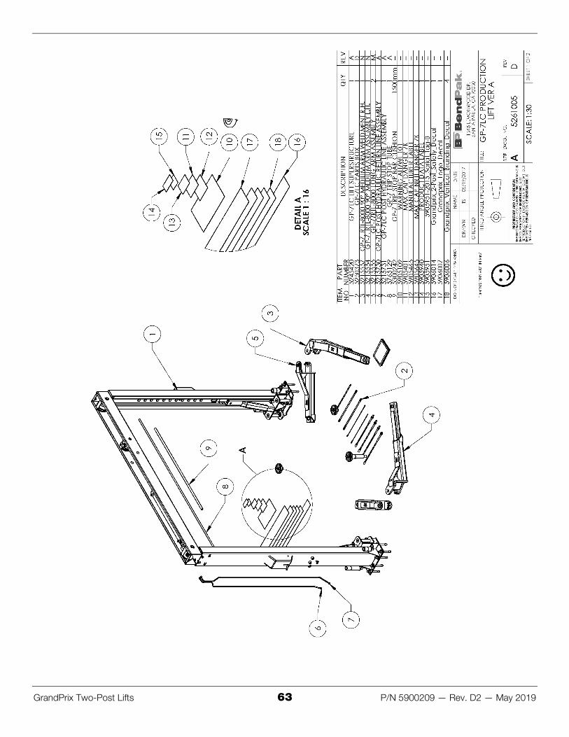
GrandPrix Two-Post Lifts 63 P/N 5900209 — Rev. D2 — May 2019

GrandPrix Two-Post Lifts 64 P/N 5900209 — Rev. D2 — May 2019

GrandPrix Two-Post Lifts 65 P/N 5900209 — Rev. D2 — May 2019

GrandPrix Two-Post Lifts 66 P/N 5900209 — Rev. D2 — May 2019

GrandPrix Two-Post Lifts 67 P/N 5900209 — Rev. D2 — May 2019
Labels

GrandPrix Two-Post Lifts 68 P/N 5900209 — Rev. D2 — May 2019

GrandPrix Two-Post Lifts 69 P/N 5900209 — Rev. D2 — May 2019

GrandPrix Two-Post Lifts 70 P/N 5900209 — Rev. D2 — May 2019

GrandPrix Two-Post Lifts 71 P/N 5900209 — Rev. D2 — May 2019
Maintenance Log

1645 Lemonwood Drive Santa Paula, CA 93060 USA
© 2019 by BendPak Inc. All rights reserved. bendpak.com