installation and operation - s&c electric company · s&c type xs fuse cutouts outdoor...
TRANSCRIPT

S&C Type XS Fuse CutoutsOutdoor Distribution (4.16 kV through 25 kV)a
May 16, 2011© S&C Electric Company Instruction Sheet 351-500
Installation and Operation
Table of Contents
Section Page Section Page
IntroductionQualified Persons . . . . . . . . . . . . . . . . . . . . . . . . . . . . . . 2Read this Instruction Sheet . . . . . . . . . . . . . . . . . . . . . . 2Retain this Instruction Sheet . . . . . . . . . . . . . . . . . . . . . 2Proper Application . . . . . . . . . . . . . . . . . . . . . . . . . . . . . 2Warranty . . . . . . . . . . . . . . . . . . . . . . . . . . . . . . . . . . . . . 3
Safety InformationUnderstanding Safety-Alert Messages . . . . . . . . . . . . . . 4Following Safety Instructions . . . . . . . . . . . . . . . . . . . . . . 4Replacement Instructions and Labels . . . . . . . . . . . . . . . 4
Safety Precautions . . . . . . . . . . . . . . . . . . . . . . . . . . . . 5
Inspection . . . . . . . . . . . . . . . . . . . . . . . . . . . . . . . . . . . . 5
InstallationMounting the Fuse Cutout . . . . . . . . . . . . . . . . . . . . . . . 6Installing the Fuse Link
(Fuse Cutouts Without Arc-Shortening Rod) . . . . . . . 7(Fuse Cutouts With Arc-Shortening Rod) . . . . . . . . . 8
Installing and Closing the Fuse Tube . . . . . . . . . . . . . . . 9Opening the Fuse Tube . . . . . . . . . . . . . . . . . . . . . . . . . 10
OperationOperation with Loadbuster® . . . . . . . . . . . . . . . . . . . . . 11
a Also applicable on 26 .4-kV through 34 .5-kV systems for protection of single-phase-to-neutral circuits (lines or transformers) only, and grounded-wye connected capacitor banks .

2 S&C Instruction Sheet 351-500
Qualified Persons Ç WARNINGThe equipment covered by this publication must be installed, operated, and maintained by qualified persons who are knowledgeable in the installation, operation, and maintenance of primary distribution fusing equipment along with associated hazards. A qualified person is one who is trained and competent in:
• The skills and techniques necessary to distinguish exposed live parts from non-live parts of electrical equipment.
• The skills and techniques necessary to determine the proper approach distances corresponding to the voltages to which the qualified person will be exposed.
• The proper use of the special precautionary techniques, personal protective equipment, insulating and shielding materials, and insulated tools for working on or near exposed energized parts of electrical equipment.
These instructions are intended only for such qualified persons. They are not intended to be a substitute for adequate training and experience in safety procedures for this type of equipment.
Read this Instruction Sheet
Thoroughly and carefully read this instruction sheet before installing or operating your S&C Type XS Fuse Cutout. The latest version is available online in PDF format at www.sandc.com. Select: Support/Product Literature Library. Familiarize yourself with “SAFETY INFORMATION” on page 4.
Retain this Instruction Sheet
This instruction sheet should be available for reference wherever fuse cutouts are used. Retain this instruction sheet in a location where you can easily retrieve and refer to it.
Proper Application Ç CAUTIONType XS Fuse Cutouts must only be used for specific fusing applications that are within the ratings of the model selected. Type XS fuse cutout ratings are listed on a ratings label attached to the unit.
Introduction

S&C Instruction Sheet 351-500 3
Introduction
Warranty The warranty and/or obligations described in S&C’s standard conditions of sale, as set forth in Price Sheet 150, plus any special warranty provisions, as set forth in the applicable product-line specification bulletin, are exclusive. The remedies provided in the former for breach of these warranties shall constitute immediate purchaser’s or end user’s exclusive remedy and a fulfillment of all seller’s liability. In no event shall seller’s liability to immediate purchaser or end user exceed the price of the specific product which gives rise to immediate purchaser’s or end user’s claim. All other warranties whether express or implied or arising by operation of law, course of dealing, usage of trade or otherwise, are excluded. The only warranties are those stated in Price Sheet 150, and THERE ARE NO EXPRESS OR IMPLIED WARRANTIES OF MERCHANTABILITY OR FITNESS FOR A PARTICULAR PURPOSE. ANY EXPRESS WARRANTY OR OTHER OBLIGATION PROVIDED IN PRICE SHEET 150 IS GRANTED ONLY TO THE IMMEDIATE PURCHASER AND END USER, AS DEFINED THEREIN. OTHER THAN AN END USER, NO REMOTE PURCHASER MAY RELY ON ANY AFFIRMATION OF FACT OR PROMISE THAT RELATES TO THE GOODS DESCRIBED HEREIN, ANY DESCRIPTION THAT RELATES TO THE GOODS, OR ANY REMEDIAL PROMISE INCLUDED IN PRICE SHEET 150.
WARRANTY QUALIFICATIONS: The standard war ranty contained in seller’s standard conditions of sale (as set forth in Price Sheet 150) does not apply to S&C Type XS Fuse Cutouts, Outdoor Distribution when installed in conjunction with fuse tubes or disconnect blades of other than S&C manufacture, nor does it apply to S&C fuse tubes and disconnect blades installed in fuse cutouts of other than S&C manufacture.d
d Current-production design fuse tubes and disconnect blades (identifi able by the catalog number supple-ment “-R10”) can be installed in con junction with earlier-design Type XS Fuse Cutouts . Also, superseded-design fuse tubes and disconnect blades (identifiable by a catalog number supplement “-R9” or lower) may be installed in conjunction with current-production Type XS Fuse Cutouts . In either case, the ratings of the com plete cutout shall be that of the fuse tube or disconnect blade .

4 S&C Instruction Sheet 351-500
Safety Information
Understanding Safety-Alert Messages
There are several types of safety-alert messages which may appear throughout this instruction sheet as well as on labels and tags attached to the Type XS Fuse Cutout. Familiarize yourself with these types of messages and the importance of the various signal words, as explained below.
Ç DANGER“DANGER” identifies the most serious and immediate hazards which will likely result in serious personal injury or death if instructions, including recommended precautions, are not followed.
Ç WARNING“WARNING” identifies hazards or unsafe practices which can result in serious personal injury or death if instructions, including recommended precautions, are not followed.
Ç CAUTION“CAUTION” identifies hazards or unsafe practices which can result in minor personal injury or product or property damage if instructions, including recommended precautions, are not followed.
NOTICE“NOTICE” identifies important procedures or requirements that, if not followed, can result in product or property damage if instructions are not followed.
Following Safety Instructions
If you do not understand any portion of this instruction sheet and need assistance, contact your nearest S&C Sales Office or S&C Authorized Distributor. Their telephone numbers are listed on S&C’s website www.sandc.com. Or call S&C Headquarters at (773) 338-1000; in Canada, call S&C Electric Canada Ltd. at (416) 249-9171.
NOTICE
Thoroughly and carefully read this instruction sheet before operating your S&C Type XS Fuse Cutout.
Replacement Instructions and Labels
If you need additional copies of this instruction sheet, contact your nearest S&C Sales Office, S&C Authorized Distributor, S&C Headquarters, or S&C Electric Canada Ltd.
It is important that any missing, damaged, or faded labels on the equipment be replaced immediately. Replacement labels are available by contacting your nearest S&C Sales Office, S&C Authorized Distributor, S&C Headquarters, or S&C Electric Canada Ltd.

S&C Instruction Sheet 351-500 5
Examine the shipment for external evidence of damage as soon after receipt as possible, preferably before removal from the carrier’s conveyance. Check the bill of lading to make sure that all shipping pallets and/or cartons are present.
If there is visible loss and/or damage:
1. Notify the delivering carrier immediately.
2. Ask for a carrier inspection.
3. Note condition of shipment on all copies of the delivery receipt.
4. File a claim with the carrier.
If concealed damage is discovered:
1. Notify the delivering carrier within 15 days of receipt of shipment.
2. Ask for a carrier inspection.
3. File a claim with the carrier.
Also notify S&C Electric Company in all instance of loss and/or damage.
Safety Precautions
Inspection
Ç DANGER
Type XS Fuse Cutouts operate at high voltage. Failure to observe the pre-cautions below will result in serious personal injury or death.
Some of these precautions may differ from your company’s operating procedures and rules. Where a discrepancy exists, follow your company’s operating procedures and rules.
1. QUALIFIED PERSONS. Access to Type XS Fuse Cutout must be restricted only to qualified persons. See “Qualified Persons” on page 2.
2. SAFETY PROCEDURES. Always follow safe operating procedures and rules.
3. PERSONAL PROTECTIVE EQUIPMENT. Always use suitable protective equipment such as rubber gloves, rub-ber mats, hard hats, safety glasses, and flash clothing in accordance with safe operating procedures and rules.
4. SAFETY LABELS AND TAGS. Do not remove or obscure any of the “DANGER,” “WARNING,” “CAU-TION,” or “NOTICE” labels and tags. Remove tags ONLY if instructed to do so.
5. ENERGIZED COMPONENTS. Always consider all parts live until de-energized, tested, and grounded.
6. OPERATING TOOLS. To close a Type XS Fuse Cutout, use a conventional insulated hookstick or S&C Universal Pole and Pole Extension fitted with an S&C Talon™ Handling Fitting or a distribution prong. To open the Type XS Fuse Cutout, use a Loadbuster®— The S&C Loadbreak Tool, attached to a conventional insulated hookstick or S&C Universal Pole.
7. MAINTAINING PROPER CLEARANCE. Always maintain proper clearance from energized compo-nents.

6 S&C Instruction Sheet 351-500
Installation
Mounting the Fuse Cutout
Ç CAUTIONTo prevent damage during transport and handling, keep the Type XS Fuse Cutout in its carton until you are ready to install it. Failure to do so can result in improper operation, arcing, or electric shock.
Step 1Attach the fuse cutout to a suitable mounting bracket as illustrated in Figure 1. NOTE: A mounting bracket, suit able for cross-arm, pole, or wall mounting, is furnished only if so specified on order by adding suffix “-B” or “-C” to catalog number of fuse cutout.
Step 2Mount the fuse cutout on the mounting bracket, as shown in Figure 1, with the carriage bolt nut snug but loose enough for pivot adjustment. Note the placement of the external-tooth lockwasher between the fuse cutout center insert and the mounting bracket. See Figure 1.
Step 3Pivot the fuse cutout to a position that will provide maxi mum ease of operation and securely tighten the carriage bolt nut.
Step 4Make electrical connections. Be sure to wire-brush any aluminum conductors and apply a coating of oxidation inhibitor before inserting such conductors in the fuse cutout connectors. Tighten connector hardware to 20 ft. lbs.
The hinge end parallel groove connector, option suffix “-D”, can be installed with the conductor in the horizontal position (standard) as shown in Figure 2. It can also be rotated 90° for the conductor to be in the vertical position as shown in Figure 3.
See “Connector Options” table on the fol-lowing page for conductor size and material which can be accommodated by each type of connector.
External-tooth lockwasherCarriage bolt
Fuse cutoutcenter insert
Lockwasher
Mounting bracket
Figure 1. Detail of attachment of fuse cutout to mounting bracket.
Figure 2. Conductor in horizontal position.
Figure 3. Conductor in vertical position.

S&C Instruction Sheet 351-500 7
Installation
Installing the Fuse Link (Fuse Cutouts Without Arc-Shortening Rod)
Step 1Hand tighten the contact button on the fuse link and care fully straighten the cable.
Step 2Remove the cap from the upper ferrule of the fuse-tube assembly. Slide the fuse link, cable end first, into the top of the fuse-tube assembly and retrieve it at the lower end.
Step 3Replace the fuse-tube cap on the fuse-tube upper ferrule and tighten the cap securely using a wrench. Loosen the cable clamping nut on the trunnion. See Figure 4.
Step 4Rotate the flipper fully about its pivot until it reaches its stop (firm resistance is felt). See Figure 4.
Hold the flipper in this position, and feed the cable through the flipper channel and around the threaded stud in a clockwise direction as shown in Figure 5.
Maintain tension on the fuse-link cable and firmly tighten the cable clamping nut, using a wrench. Do not overtighten the cable clamp-ing nut.
Step 5Clip excess cable to within Z\x inch (13 mm) of the nut.
Figure 4. Flipper fully pivoted.
Bottom of fuse tubeFlipper
Cable clamping nut
Trunnion
Figure 5. Cable under tension around nut.
Flipper channel
Cable clamping nut
Trunnion
CONNECTOR OPTIONS
ItemAccommodating Conductors
PositionCatalog Number
SuffixQuantity Size and Material
Parallel-Groove Connectors Two
No . 6 solid (13 .3 mm2) through No . 2 stranded (44 .4 mm2) copper or aluminum in one groove; No . 2 solid (33 .6 mm2) through 250 kc mil (168 mm2) stranded copper or aluminum or 4/0 ACSR (161 mm2) in the other groove
Standard Orientation
-D
Eye-Bolt Connectors OneNo . 8 solid (8 .4 mm2) through 250 kc mil (168 mm2) stranded copper or aluminum, or 4/0 ACSR (161 mm2)
Standard Orientation
-M
Lower Connector Rotated 90°
-M90
8 S&C Instruction Sheet 351-500
Installation
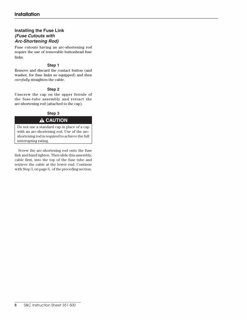
Installing the Fuse Link (Fuse Cutouts with Arc-Shortening Rod)Fuse cutouts having an arc-shortening rod require the use of removable buttonhead fuse links.
Step 1Remove and discard the contact button (and washer, for fuse links so equipped) and then carefully straighten the cable.
Step 2Unscrew the cap on the upper ferrule of the fuse-tube assembly and retract the arc-shortening rod (attached to the cap).
Step 3
Ç CAUTIONDo not use a standard cap in place of a cap with an arc-shortening rod. Use of the arc-shortening rod is re quired to achieve the full interrupting rating.
Screw the arc-shortening rod onto the fuse link and hand tighten. Then slide this assembly, cable first, into the top of the fuse tube and retrieve the cable at the lower end. Continue with Step 3, on page 6, of the preceding section.

S&C Instruction Sheet 351-500 9
Installation
Installing and Closing the Fuse TubeOnly qualified persons should operate, inspect, or main tain a fuse cutout.
Such qualified persons should wear protec-tive equipment such as rubber gloves, hard hat, . . . safety glasses, flash-clothes, etc., in accordance with established safety practices, and be trained in their proper care.
Ç WARNINGHot gases and fuse link particles can be expelled at high velocity during interruption. When closing a fuse cut out, all personnel should be positioned well clear of its exhaust.
Step 1After installing the fuse link as described in the foregoing sections, insert the prong of a hookstick into the opening under the trunnion casting band. Or, as an alternate, insert the prong in the keyhole opening in the trunnion casting band.
Step 2Guide the fuse tube into the fuse cutout hinge as shown in Figure 6 and disengage the hookstick.
Step 3Insert the prong of the hookstick in the pull ring on the upper ferrule of the fuse tube and swing the fuse tube to within approximately 45º of the fully closed position. Then, while looking away from the fuse cutout, drive the fuse tube to the closed position using a vigorous thrust. Carefully disengage the hookstick taking care to avoid opening the fuse tube.
Ç DANGERS&C Type XS Fuse Cutouts are designed to protect equipment. A fuse cutout cannot protect personnel from injury or electrocu-tion if contact is made with energized circuits or hardware.
Figure 6. Installing the fuse tube.
Fuse cutout hinge
KeyholeHookstick prong
Trunnion casting band

10 S&C Instruction Sheet 351-500
Installation
Opening the Fuse Tube
Ç WARNINGDo not attempt to open S&C Type XS Fuse Cutouts to interrupt load current, without the use of a loadbreak tool such as S&C’s Loadbuster®. An arc started by opening a fuse cutout under load without a loadbreak tool could cause injury or damage to equipment.
S&C’s Loadbuster is ideally suited for use in opening the fuse tube of S&C Type XS Fuse Cutouts (or other fuse cut outs and disconnects designed for use with Loadbuster). Loadbuster is S&C’s unique method of providing low-cost, positive, and convenient live-switching capability for such devices. Instructions for use of Loadbuster with S&C Type XS Fuse Cutouts are shown below.
Following an opening operation using Load-buster, the fuse tube can be lifted out of the fuse cutout hinge using the prong of a hookstick. See Figure 3 on page 6.
Ç IMPORTANTA fuse tube should not be left in the open position for an extended period of time, since water can damage the tube lining.

S&C Instruction Sheet 351-500 11
Operation
Operating with LoadbusterCheck for proper resetting of the Loadbuster by extending the tool about three inches by hand. Through out this travel, an increasing spring resistance should be felt.
Step 1Reach across in front of the fuse cutout with Loadbuster and hook the anchor, located at the top of Loadbuster, over the attachment hook on the far side of the fuse cut out. See Figure 7.
Step 2Swing Loadbuster toward the fuse tube and pass the Loadbuster pull-ring hook through the pull ring on the fuse tube. The pull-ring latch will deflect and upon com plete entry of the pull ring, will spring back, locking Load buster to the pull ring. Loadbuster is now connected across the upper contact of the fuse cutout. See Figure 7.
Step 3To open the circuit, operate Loadbuster with a firm, steady pull until it is extended to its maximum length. See Figure 8. Avoid jerking and hesitation. The resetting latch will keep it open. Generally, there will be no indica tion of circuit interruption, but commutation arcing may be noted at the pull-ring hook and at the anchor, particu larly when interrupting load currents approaching the rating of the tool. The only sound will be that of Load buster tripping.
Step 4To detach Loadbuster after circuit interruption, first raise it slightly and disengage the anchor from the attachment hook.
Ç WARNINGWhen Loadbuster is raised the open gap distance is re duced. Careless manipulation could decrease the open gap to the point where flashover will occur.
Next, bring the fuse tube toward its fully open position as illustrated in Figure 9. Then remove Loadbuster from the pull ring by turning the pole. This will deflect the pull-ring latch to release the pull ring. Because the fuse tube will drop fully open by gravity, it may be preferred to remove Loadbuster by “rolling” it off both the attachment hook and pull ring at the same time merely by twisting the pole after Loadbuster has been tripped and fully extended. To perform this operation easily and smoothly, always roll Load-buster so that it rotates in an upward direction.
Figure 8. Loadbuster in tripped position.
Figure 9. Detaching Load buster from fuse cutout.
Figure 7. Loadbuster connected to S&C Type XS Fuse Cutout, Outdoor Distribution.
Pull ring
Pull-ring latch
Pull-ring hook
Attachment hook
Anchor

Prin
ted
in U
.S .A
.
12 S&C Instruction Sheet 351-500
Operation
Step 5To reset Loadbuster for the next operation, hold as shown in Figure 10. Extend the tool slightly and lift the resetting latch with the thumb. With the latch up, telescope the tool completely so the trigger can reset itself. Check for proper resetting by extending the tool about three inches. Throughout this travel an increasing spring resistance should be felt.
Figure 10. Resetting Loadbuster.
Resetting latch