installation and operations manual - fti, diesel · pdf fileinstallation and operations manual...
TRANSCRIPT

Automated
Fuel Maintenance
System
MODEL FTI-2.8
FUEL TECHNOLOGIES INTERNATIONAL
Installation
and
Operations Manual
03/01/2011 - Fuel Technologies - FTI-2.8

2
OPERATIONS & MAINTENANCE
CONTENTS
Installation Notes...................................................................................Page 3
Overview............................................................................................... Page 4
Identifying Parts.................................................................................... Page 5 Operating System...................................................................................Page 6
Seven Day Time Clock Info.................................................................... Page 6
Set the Current Time ……........................................................................Page 7
Set Start Time, Stop Time & Day of the Week Run Time..……………...…..Page 8
Time Clock Examples .............................................................................Page 8 How to Calculate Filtering Run Times………….……………………………....…….Page 8
How to Change the Filter.......................................................................Page 9
How to Drain the Water Separator.........................................................Page 9
Replacement Filter List...........................................................................Page 9
Cabinet Drawing……………………………………..………...…………………...……….Page 10
Electrical Diagrams...........................…..........................................Pages 11-13 Start Up Checklist..........................................…….................................Page 14 Limited Warranty..........................................….....................................Page 15

3
Installation Notes
1. FTI filtration system should operate on all fuel storage tanks. A qualified plumbing contractor and a qualified electrical contractor should complete all installations.
2. Wall mount or pedestal mount should be bolted into place.
3. 115/208-230V AC, 15 Amp. Single-phase power source must be available at system location.
4. Pipe plugs are installed in the supply and return line for shipping purposes only, and must be removed prior to installation.
5. Holes need to be added in cabinet for electrical, fuel supply and return lines.
6. All FTI models are factory tested using lightweight oil. Some of this fluid may remain in the system. It will not interfere with the performance of the system.
7. Ball valves shall be installed on the fuel supply line and return line to isolate the system for any required filter maintenance.
8. Supply line shall be installed at the sump end of the storage tank 1” from the bottom and plumbed to the fuel maintenance system. A foot valve shall be installed on supply line to keep system primed.
9. Return line shall be installed to return fuel to the opposite end of the storage tank. A check valve may be required on return line, on some installations to prevent back flow pressure.
10. Caution should be taken not to exceed the 15-ft. vertical suction lift capability of the fuel circulation pump.
11. Fuel Technologies Stabilizer and Biocide to be added to the existing fuel, and when additional fuel is added to storage tank.
12. A priming tee or other means of filling fuel supply line with fuel shall be installed.
DO NOT RUN LONGER THAN THREE MINUTES WITHOUT FLUIDS
1. On initial startup, if the system does not fill with fluid the pump may require priming.
2. To prime the pump, remove the filter. Fill filter with diesel fuel or light oil and replace. Restart the system.
3. If filling filter fails to prime pump, fill entire fuel line with fuel and restart.
INSTALLATION PRECAUTIONS:
THE MODEL FTI-2.8 HAS NO PROTECTION AGAINST THERMAL EXPANSION OF THE FUEL LINES. IF THE FUEL LINES ARE INSTALLED WITHOUT PRESSURE RELIEF, DAMAGE MAY OCCUR TO THE PUMP, MOTOR OR FILTER. INSTALLER SHOULD PREVENT ANY CLOSED LOOP WITH THE FTI-2.8 SYSTEM IN THE MIDDLE.
FTI WILL NOT BE RESPONSIBLE FOR ANY DAMAGE DUE TO EXCESSIVE LINE PRESSURE CAUSED BY FUEL THERMAL EXPANSION.

4
Overview
1. FTI-2.8 Fuel Maintenance System is designed for ease of operation. Due to its relatively small size and weight it can be installed in most locations easily. 2. How often you need to clean stored fuel will vary upon tank conditions and current fuel condition. 3. Your FTI system uses a two-stage, filtering and water removal process. It has a 7-day programmable PLC with memory backup. (memory backup will last approximately 80 hours without power.) 4. High vacuum alarm, leak detector alarm, motor overload alarm, and a filter high water alarm will automatically turn system off, and sound an audible alarm. A brief alarm description will appear on the touch screen. 5. A dry contact for general alarm notification (NO) is available in the control panel. The contact can be used for remote alarm status. 6. A dry contact to shut off the FTI system for any event is available. It is labeled “Generator on” “FTI system off” 7. Depending on the condition of the fuel to be maintained, you may initially be changing filters more frequently than expected. By monitoring the vacuum gauge the operator can determine when it is time to change the filter. (filter plugged factory set at 16 - 18 in.hg.). 8. As the fuel quality progressively improves, you will notice a dramatic drop in filter usage. In cases of extreme contamination, it is recommended that you have your fuel polished prior to initial use of your FTI system. The FTI system is designed to keep clean fuel clean. Continued use prevents the fuel from deteriorating again and maintains a healthier environment to protect the engine, the fuel, and the storage tank.
HOW IT WORKS

5
13
FTI-2.8
Identifying Parts
14
1. Control Panel
2. Fuel Return Line Connection (SS Union)
3. Pump 2.8 GPM
4. Leak Detector
5. 1/3 HP Motor
6. Water Sensor Probe
7. Water Drain
8. Water Separator and 2 Micron Particulate
9. Fuel Supply Line Connection
10. Vacuum Switch Gauge
11. Model No., Serial No., FM Approved
12. Lockable Disconnect Switch
13. Alarm Horn
14. LED
15. Touch Screen
4 5
11
1
12
6
2 3
15 10
8
7
9
6
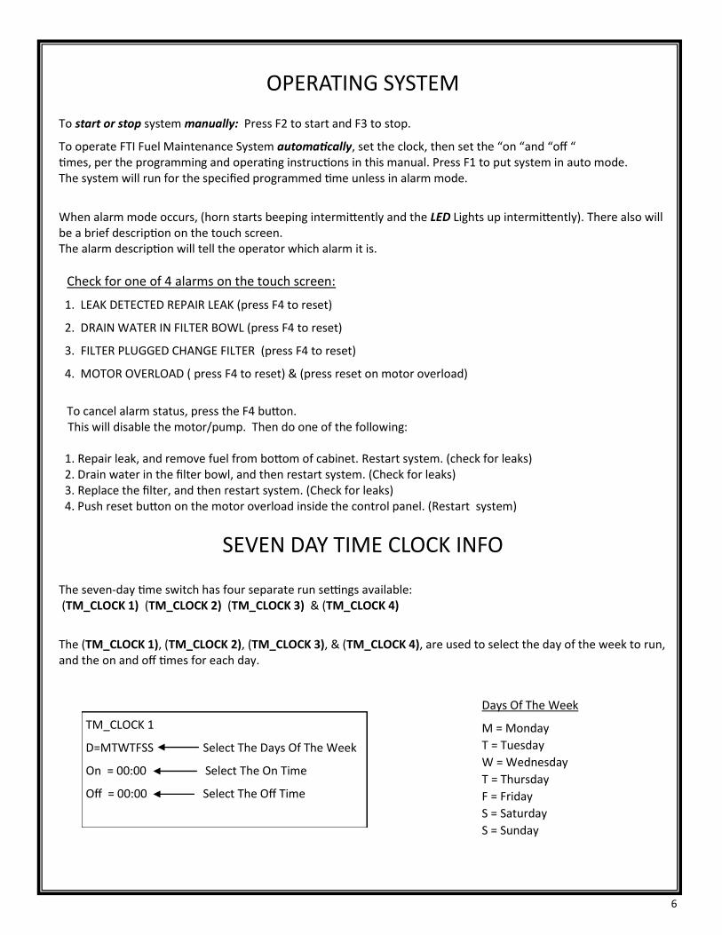
OPERATING SYSTEM
To start or stop system manually: Press F2 to start and F3 to stop.
To operate FTI Fuel Maintenance System automatically, set the clock, then set the “on “and “off “ times, per the programming and operating instructions in this manual. Press F1 to put system in auto mode. The system will run for the specified programmed time unless in alarm mode.
When alarm mode occurs, (horn starts beeping intermittently and the LED Lights up intermittently). There also will be a brief description on the touch screen. The alarm description will tell the operator which alarm it is.
Check for one of 4 alarms on the touch screen:
1. LEAK DETECTED REPAIR LEAK (press F4 to reset)
2. DRAIN WATER IN FILTER BOWL (press F4 to reset)
3. FILTER PLUGGED CHANGE FILTER (press F4 to reset)
4. MOTOR OVERLOAD ( press F4 to reset) & (press reset on motor overload)
To cancel alarm status, press the F4 button. This will disable the motor/pump. Then do one of the following: 1. Repair leak, and remove fuel from bottom of cabinet. Restart system. (check for leaks) 2. Drain water in the filter bowl, and then restart system. (Check for leaks) 3. Replace the filter, and then restart system. (Check for leaks) 4. Push reset button on the motor overload inside the control panel. (Restart system)
SEVEN DAY TIME CLOCK INFO
The seven-day time switch has four separate run settings available: (TM_CLOCK 1) (TM_CLOCK 2) (TM_CLOCK 3) & (TM_CLOCK 4)
The (TM_CLOCK 1), (TM_CLOCK 2), (TM_CLOCK 3), & (TM_CLOCK 4), are used to select the day of the week to run, and the on and off times for each day.
TM_CLOCK 1
D=MTWTFSS Select The Days Of The Week
On = 00:00 Select The On Time
Off = 00:00 Select The Off Time
Days Of The Week
M = Monday
T = Tuesday
W = Wednesday
T = Thursday
F = Friday
S = Saturday
S = Sunday

7
SET THE CURRENT TIME
1. Push the down arrow button and then the ESC button. The screen will read as follows: >Stop
Set Param Msg Config Set..
2. Push the down arrow button to put the cursor > to Set. Then push OK button. 3. The next screen “Clock” is on the top with the cursor to the left, push OK button. 4. The next screen “Set Clock” will appear. Push the OK button.
The screen will read as follows:
Blinking Curser
5. To change the day push the up arrow button or down arrow button to scroll to the correct Day. 6. Then push the right arrow button to move the blinking cursor to the first number to set the correct time. Push the up arrow button or the down arrow button to change the numbers for the correct time. Do this for the four numbers. 7. After changing the last number in the time slot, push the right arrow button to move the cursor to the first position to set the current Year (YYYY), Month (MM), and Day (DD). 8. Press the OK button when finished, make sure the cursor is blinking on the last number for the Day (DD). 9. Press the ESC button apx. 3 times to return to the default screen.
1. F1=Sets system in Auto Mode, F2 = Manual On, F3 = Manual & Auto Off , F4 = Cancel Alarms 2. The arrow buttons are used to navigate up, down, left or right. 3. The ESC key moves between screens. 4. The OK button accepts programming changes.
SET CLOCK
SA 13:29
YYYY-MM-DD
2009-09-12

8
Set Start Time, Stop Time & Day of the Week Run Time 1. Press the ESC button.
2. Push the down arrow button to move cursor > to the Set Param.
3. Press the OK button. This screen will appear:
4. Press OK button, the blinking cursor is now on the first dash mark. ( D = - - - - - - - ) 5. Push the up arrow button to change the dash to a M if you want the system to run on Mondays.
6. Push the right arrow button to move cursor to other days of the week . Choose only the days you want your system to run. Dash ( - ) means it will not run. 7. With blinking cursor on the last day selection push the right arrow to move cursor to the first number for the On (run time) selection. ( On = - -: - - ) 8. Push the up arrow or the down arrow to set the correct start time for the system to run. Continue with other numbers to set the ON time And the OFF time.
9. You can set any time between 00:00 and 23:59.
10. With blinking cursor on the last number of the OFF time press the OK button.
11. Press the down arrow to change TM_CLOCK 2, TM_CLOCK 3, or TM_CLOCK 4 for additional settings. 12. If at any time you want to exit the setup screen keep pushing the ESC button until the default screen appears.
Time Clock Examples 1. In example 1 below, the system is set to run on every day from 5:30 AM to 7:40 AM. ( TM_CLOCK 1) 2. In example 2, the system will run every Tuesday from 3:10 PM to 6:15 PM. ( TM_CLOCK 2 ) 3. In example 3, the system will run every Saturday and Sunday from 8:30 PM to11:45 PM.( TM_CLOCK 3)
Example 1
TM_CLOCK 1
D=MTWTFSS
On = 05:30
Off = 07:40
Example 2
TM_CLOCK 2
D= -T -- - - -
On = 15:10
Off = 18:15
Example 3
TM_CLOCK 3
D= - - - - - SS
On = 20:30
Off = 23:45
TM_CLOCK 1
D=----------------
On=--------------
Off=--------------
(D = MTWTFSS)
How to calculate the time to clean 25% of the fuel weekly
1. Determine how many gallons are in the storage tank (Example: 1000 Gallons)
2. 25% of the tank = (250 gallons)
3. 2.8 gpm X 60 minutes = 168 gallons per hour
4. Divide 168 gallons into 250 gallons = 1.48 hours
5. Program PLC to run 1.5 hours
9
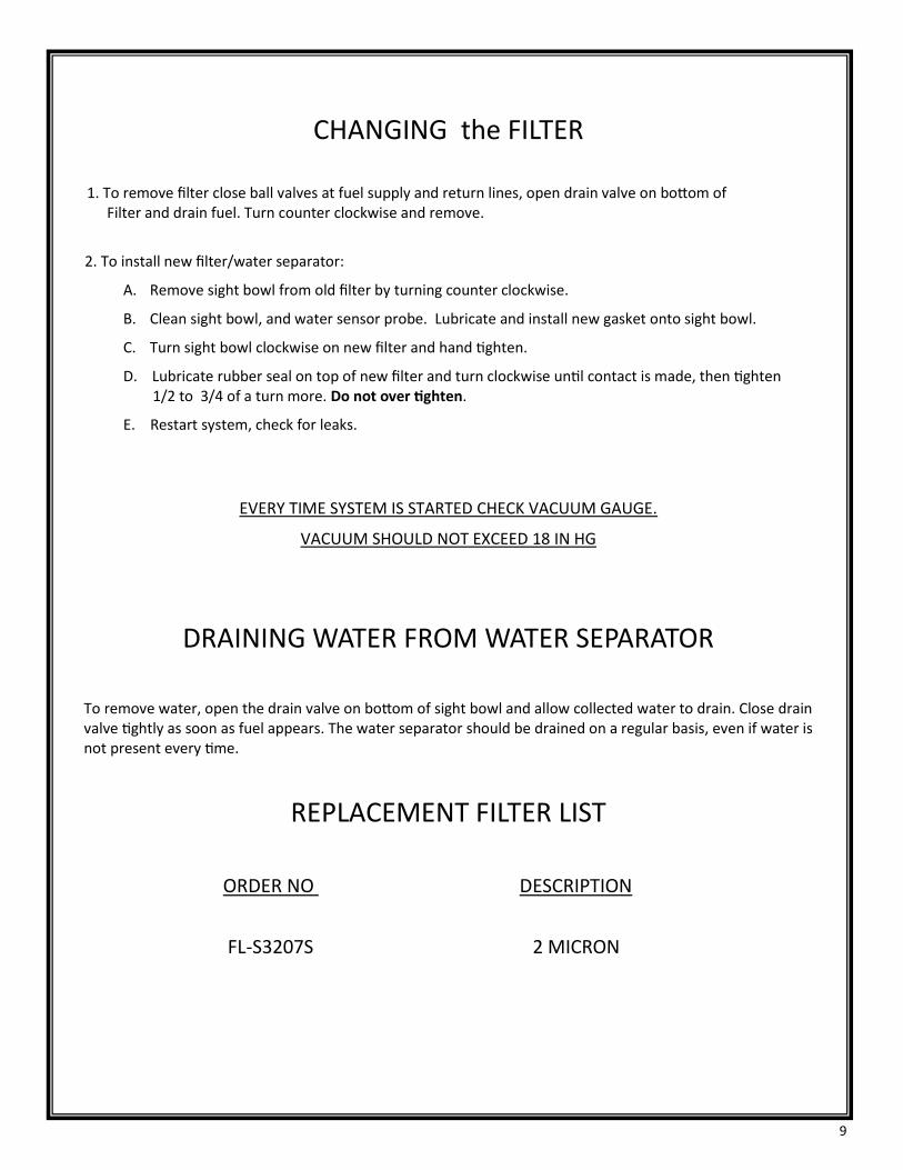
CHANGING the FILTER
1. To remove filter close ball valves at fuel supply and return lines, open drain valve on bottom of Filter and drain fuel. Turn counter clockwise and remove.
2. To install new filter/water separator:
A. Remove sight bowl from old filter by turning counter clockwise.
B. Clean sight bowl, and water sensor probe. Lubricate and install new gasket onto sight bowl.
C. Turn sight bowl clockwise on new filter and hand tighten.
D. Lubricate rubber seal on top of new filter and turn clockwise until contact is made, then tighten 1/2 to 3/4 of a turn more. Do not over tighten.
E. Restart system, check for leaks.
EVERY TIME SYSTEM IS STARTED CHECK VACUUM GAUGE.
VACUUM SHOULD NOT EXCEED 18 IN HG
DRAINING WATER FROM WATER SEPARATOR
To remove water, open the drain valve on bottom of sight bowl and allow collected water to drain. Close drain valve tightly as soon as fuel appears. The water separator should be drained on a regular basis, even if water is not present every time.
REPLACEMENT FILTER LIST
ORDER NO DESCRIPTION
FL-S3207S 2 MICRON

10

11

12

13

14
FTI AUTOMATED FILTRATION SYSTEM START-UP CHECK LIST
Technician ___________________________________Observer__________________________________
1. System to be tested: FTI Automated Filtration System – Model FTI-2.8
2. FTI Filtration System Test Procedure
A. Program system to automatically filter for 1 hour. Reset clock to within 1-5 minutes of start time. (see operations manual for instructions) Place the panel in the AUTO mode Wait for filtration to start.
1.) Check FILTER PUMP RUNNING status.
Notes:____________________________________________________________________________________ _________________________________________________________________________________________
B. Place the panel in the MANUAL mode. Start manual filtration.
1.) Check FILTER PUMP RUNNING status.
Notes:____________________________________________________________________________________________________________________________________________________________________________
C. Simulate a strainer high vacuum alarm at the strainer ball valve. (not included from factory) Slowly close supply line ball valve until the vacuum alarm sounds. Check gauge needle position (16-18Hg.)
1.) Check filter high vacuum alarm. (16-18 in hg)
Notes:_____________________________________________________________________________________________________________________________________________________________________________
D. Simulate a leak in cabinet. Lift leak detector. Alarm will sound. Reset control panel.
1.) Check leak alarm.
Notes:_____________________________________________________________________________________________________________________________________________________________________________
E. Simulate motor overload. With control panel door open and the system is running push the test button o the motor overload inside panel.
1.) Check motor is stopped and correct alarm description on the touch screen.
Notes:_____________________________________________________________________________________________________________________________________________________________________________
F. Simulate water full in the collection bowl. Remove water sensor cable and short with wire between the two pins.
1.) Check Water alarm.
Notes:_____________________________________________________________________________________________________________________________________________________________________________
TEST COMPLETE

15
LIMITED WARRANTY
FUEL TECHNOLOGIES INTERNATIONAL LLC (FTI) makes every effort to assure that its products meet high quality and
durability standards, and we expressly warrant the original consumer/purchaser of our products that each product is
free from defects in materials and workmanship. Our expressed warranty is subject to the following terms and condi-
tions:
1. The term of our warranty is one year from the date of purchase. A warranty claim received by us after one year
from the date of purchase will not be honored even if it is claimed that the defect occurred prior to one year from
the date of purchase.
2. Our warranty does not cover defects due, directly or indirectly, to misuse, abuse, negligence of others, repairs or
alterations done outside of our facilities, or lack of maintenance.
3. Our liability for breach of our express warranty is limited to the repair or replacement of the product , at our cost.
4. We are not liable for general, special, consequential, incidental or contingent damages resulting, directly or indi-
rectly, from the purchase or use of our products.
WE DISCLAIM ALL WARRANTIES OF MERCHANTABIL ITY AND FITNESS FOR ANY PURPOSE OF OUR PROD-UCTS.
To make a claim under this warranty, call our Customer Service Representative at 1-805-925-0531. We will ask you to
advise us of our Distributor’s name and address, the date of purchase, model number, and a detailed explanation of
the problem you are experiencing. The Customer Service Representative will arrange for a Field Engineer to inspect
your system. If our inspection discloses a defect covered by our limited warranty, we will either repair or replace the
defective parts of products at our election, and at our cost. If upon inspection, our Engineer determines there is not
defect or that the damage to the system resulted from causes not within the scope of our limited warranty, then you
must bear the cost of repair or replacement of damaged parts. For service, please contact your local Distributor.
For your records
Model No. Date of Purchase: