installation and operations manual - powrtran
TRANSCRIPT

INSTALLATION AND OPERATIONS MANUAL


TameThe Waves 3
Introduction
Thank you for your purchase of the most advanced and user-friendly electromechanical trim tabs on the market.
The Pro Tabs were developed out of a necessity for a trim tab which could be deployed at higher speeds without bending or breaking. The unique angles and bends of our electropolished tabs provide additional bracing and strength, while directing waterflow to reduce drag.
Contained in this manual, you will find detailed, step-by-step installation instructions, as well as, an overview of tab operation. Please read through this manual in its entirety before beginning installation. It is also highly recommended to keep this manual accessible at all times.
If you have any questions, please call our Technical Service line at 1-800-466-7697
24253 COUNTY ROAD 7 ST. CLOUD, MN 563011-800-466-7697 WWW.POWRTRAN.COM
A DIVISION OF

4
Use of This Manual
This Installation and Operations Manual is an important part of the product and should be thoroughly read and understood by anyone in charge of the installation or use of the Pro Tabs.
This manual will use the following symbols to ensure user safety and guarantee correct installation and operation.
! DANGER
! WARNING
! CAUTION
! NOTICE
Immediate hazards which cause severe injury or death.
A hazard exists which can result in injury or death if proper precautions are not taken.
A reminder of safety practices or a direction of attention to unsafe practices which could result in injury.
Important information for the correct installation and maintenance, that does not cause any damage.
PORTSTARBOARD
STERN
BOW
Nautical terms used in this manual
TameThe Waves 5
Product Description
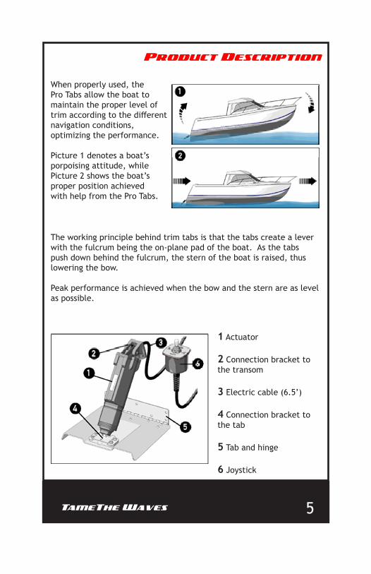
When properly used, the Pro Tabs allow the boat to maintain the proper level of trim according to the different navigation conditions, optimizing the performance.
Picture 1 denotes a boat’s porpoising attitude, while Picture 2 shows the boat’s proper position achieved with help from the Pro Tabs.
The working principle behind trim tabs is that the tabs create a lever with the fulcrum being the on-plane pad of the boat. As the tabs push down behind the fulcrum, the stern of the boat is raised, thus lowering the bow.
Peak performance is achieved when the bow and the stern are as level as possible.
1 Actuator
2 Connection bracket to the transom
3 Electric cable (6.5’)
4 Connection bracket to the tab
5 Tab and hinge
6 Joystick
6
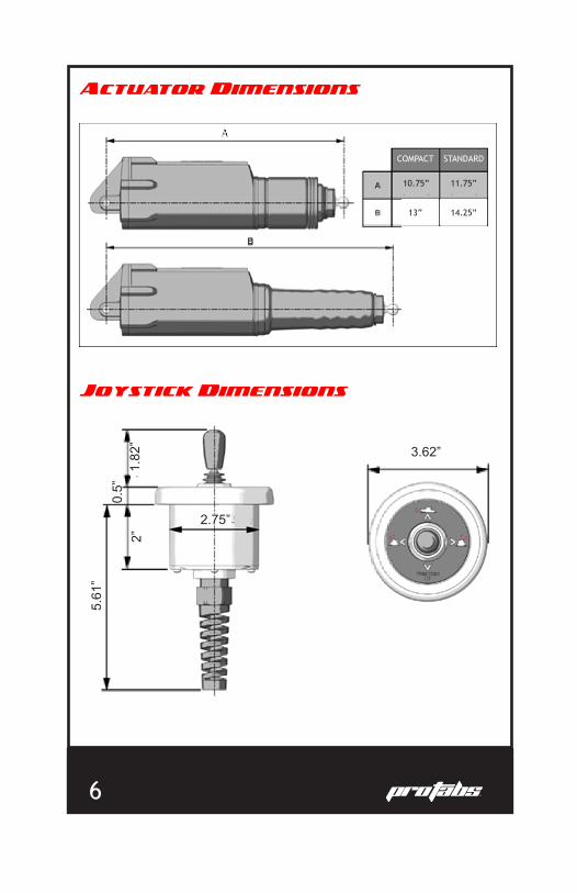
Actuator Dimensions
Joystick Dimensions
COMPACT STANDARD
10.75” 11.75”
14.25”13”
2.75”
3.62”
2”
5.61
”
1.82
”0.
5”

TameThe Waves 7
TAB Dimensions
Sizing Guidelines
BOAT LENGTH14’-18’
14’-18’
9” x 9” 12.22”12.22”12.22”12.22”
9” x 9” 10.65” 12”10.65” 12”10.65” 12”10.65” 12”
12” x 9”
12” x 9”
12” x 12”
12” x 12”
12” x 18”
12” x 18”
16’-25’
16’-25’
18’-30’
18’-30’
26’-36’
26’-36’
BOAT LENGTH
TAB SIZE (L X W)
TAB SIZE (L X W)
TRANSOM MIN. HEIGHT
TRANSOM MIN. HEIGHTTILTED INSTALLATION VERT. INSTALLATION
STANDARD ACTUATOR
COMPACT ACTUATOR
STANDARD DIMENSIONSA 9” 12” 12” 12”
9” 9” 12” 18”B
INCHES
1.1”

8
Installation Overview
Installation Steps
1 Find the tab installation point as shown in the picture.
Tools Required
7/32”25/64”
10mm
Hole Saw2.75”
Please read all instructions carefully BEFORE beginning installation. Improper installation can lead to failures which can cause injury.
! WARNINGMake sure the Upper Fixing Bracket of the actuator is not near other devices on the inner part of the transom which may obstruct the passing of the power cable.
Ensure hinge is paralell to the bottom of the hull.
The inside edge of the tab must be at least
8” from the centerline of the transom.
The side corner of the hinge must be a minimum of 2” from the fairing.
2”2”
The outside edge of the tab must be at least 1-4” from the edge of the keel.
1-4”
>_
>_>_
8” 3/8”

TameThe Waves 9
2
3
Locate the hole pattern you will be using.
Mark the hole positions on your transom. Then make preholes using your 7/32” drill bit.
! NOTICE
! NOTICE
In order to ensure proper fitment and installation of the tabs, use the bigger holes indicated by the in the picture.
The smaller holes indicated by the are used for installations which are replacing other systems.
The holes should be drilled to a maximum depth of 1.25”.
10
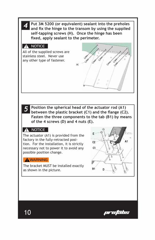
4
5
Put 3M 5200 (or equivalent) sealant into the preholes and fix the hinge to the transom by using the supplied self-tapping screws (H). Once the hinge has been fixed, apply sealant to the perimeter.
Position the spherical head of the actuator rod (A1) between the plastic bracket (C1) and the flange (C2). Fasten the three components to the tab (B1) by means of the 4 screws (D) and 4 nuts (E).
! NOTICE
! NOTICE
All of the supplied screws are stainless steel. Never use any other type of fastener.
The actuator (A1) is provided from the factory in the fully-retracted posi-tion. For the installation, it is strictly necessary not to power it to avoid any possible position change.
The bracket MUST be installed exactly as shown in the picture.
! WARNING

TameThe Waves 11
6 Insert the upper bracket (G1) on actuator (A1) using only the pin (G2) but NOT the split pin (G3). DO NOT insert the cable through the bracket at this time.
! NOTICEThe upper bracket also allows the assembly of the actuator in a ver-tical position. The possible posi-tions are shown in the picture.
! CAUTIONThe bracket on the tab side allows an articulation of up to 7 degrees of the actuator (see image). If this angle is exceeded for the installation, the upper bracket may break.
3.5° 3.5°
12
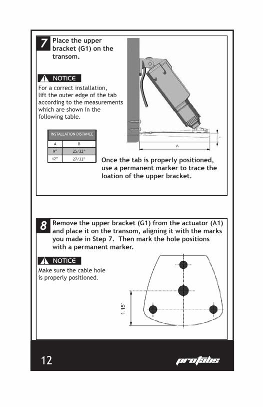
7 Place the upper bracket (G1) on the transom.
Once the tab is properly positioned, use a permanent marker to trace the loation of the upper bracket.
! NOTICEFor a correct installation, lift the outer edge of the tab according to the measurements which are shown in the following table.
INSTALLATION DISTANCE
A B
27/32”
25/32”9”
12”
8 Remove the upper bracket (G1) from the actuator (A1) and place it on the transom, aligning it with the marks you made in Step 7. Then mark the hole positions with a permanent marker.
! NOTICEMake sure the cable hole is properly positioned.
1.15
”
TameThe Waves 13
9
10
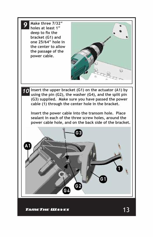
Make three 7/32” holes at least 1” deep to fix the bracket (G1) and one 25/64” hole in the center to allow the passage of the power cable.
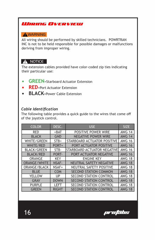
Insert the upper bracket (G1) on the actuator (A1) by using the pin (G2), the washer (G4), and the split pin (G3) supplied. Make sure you have passed the power cable (1) through the center hole in the bracket.
Insert the power cable into the transom hole. Place sealant in each of the three screw holes, around the power cable hole, and on the back side of the bracket.

14
11
13
12
Fix the upper bracket (G1) by means of the supplied screws.
Mark your hole location and cut it out with a 2.75” hole saw.
Refer to the joystick dimensions on pg. 6 or cut out and use the diagram on pg. 23 to determine where you will mount your joystick.
! NOTICEWait for the sealant to dry. Proper dry-time will be dependant on brand of sealant used and should be found on the packaging. 1.
15”

TameThe Waves 15
14
15
Assemble the joystick as shown below. There is a small hole in the face of the koystick and a small knob on the back of the faceplate. Lining these up will allow you to install the joystick properly.
Position the joystick where you want it and use the 4 supplied screws to secure it in place.
! NOTICEYou must install the plastic bezel to prevent the faceplate from coming loose and falling off.
16
Wiring Overview
COLOR DESC. USE SIZERED +BAT POSITIVE POWER WIRE AWG 14
AWG 14AWG 16AWG 16AWG 16AWG 16AWG 18AWG 18AWG 18AWG 18AWG 18AWG 18AWG 18AWG 18
NEGATIVE POWER WIRESTARBOARD ACTUATOR POSITIVE
PORT ACTUATOR POSITIVESTARBOARD ACTUATOR NEGATIVE
PORT ACTUATOR NEGATIVEENGINE KEY
NEUTRAL SAFETY NEGATIVENEUTRAL SAFETY POSITIVESECOND STATION COMMONSECOND STATION CONTROLSECOND STATION CONTROLSECOND STATION CONTROLSECOND STATION CONTROL
GNDSTB+
PORT+STB-
PORT-KEY
NSAF-NSAF+COMUP
DOWNLEFT
RIGHT
BLACKWHITE/GREEN
WHITE/RED
BLACK/REDBLACK/GREEN
ORANGEORANGE/WHITEORANGE/BLACK
BLUEYELLOW
GRAYPURPLEGREEN
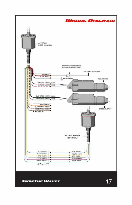
! WARNINGAll wiring should be performed by skilled technicians. POWRTRAN INC is not to be held responsible for possible damages or malfunctions deriving from improper wiring.
The extension cables provided have color-coded zip ties indicating their particular use:
• GREEN=Starboard Actuator Extension
• RED=Port Actuator Extension
• BLACK=Power Cable Extension
! NOTICE
Cable IdentificationThe following table provides a quick guide to the wires that come off of the joystick control.
TameThe Waves 17
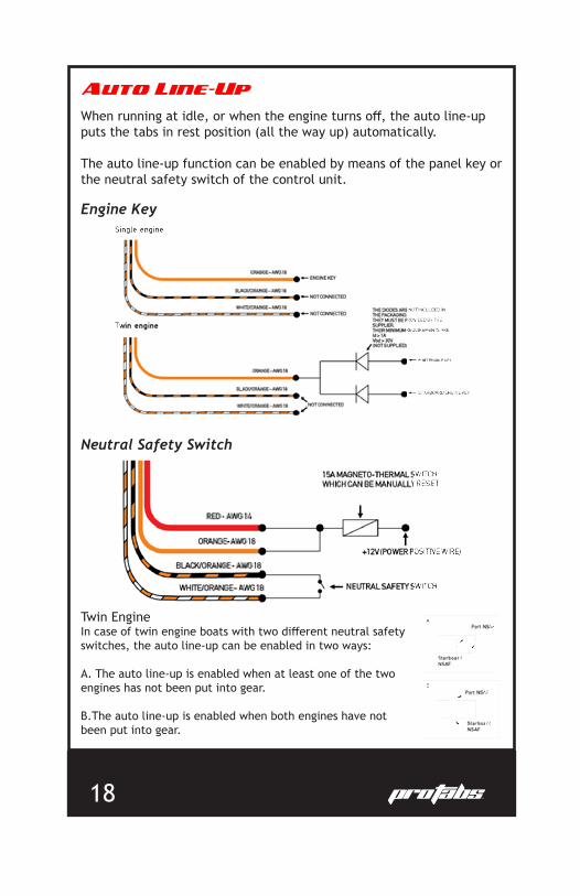
Wiring Diagram
18
Auto Line-Up
When running at idle, or when the engine turns off, the auto line-up puts the tabs in rest position (all the way up) automatically.
The auto line-up function can be enabled by means of the panel key or the neutral safety switch of the control unit.
Engine Key
Neutral Safety Switch
Twin EngineIn case of twin engine boats with two different neutral safety switches, the auto line-up can be enabled in two ways:
A. The auto line-up is enabled when at least one of the two engines has not been put into gear.
B.The auto line-up is enabled when both engines have not been put into gear.

TameThe Waves 19
Maintenance
Proper maintenance is an important factor for the safety and life of your Pro Tabs. Only skilled and properly trained staff should carry out maintenance operations.
The design and materials used to manufacture the Pro Tabs reduce maintenance operations to a minimum.
Technical SupportFor Technical Support, please contact Powrtran Inc. at
1-800-466-7697 or email [email protected]
! WARNING
! WARNING
The main safety warnings to be observed during maintenance are:
• DO NOT wear rings, watches, etc. during maintenance operations.
• ALWAYS wear gloves and proper eye protection.• DO NOT use free flames, sharp edges, or pins for cleaning.• DO NOT smoke.
Before the beginning of each season, check that:
• Fixing screws are firmly fashioned.• There is no marine growth on the actuator or any moving parts.
To discourage any marine growth on tab, antifouling paint can be applied. When applying the paint to the actuator, make sure it is fully retracted.
! NOTICE

20
Trim Tab Use
The electronic system can automatically enable an important function named “Auto line-up” which allows aligning of the tabs at rest without using the joystick.
As explained in the Wiring section, two different kinds of installation are available; Engine Key Control or Neutral Safety Switch Control.
This function is provided with an inhibition device that prevents it from being enabled again for five minutes. After this time has passed, the “Auto line-up” function is available again.
If, for any reason, you wish for the joystick control to behave opposite of this setup, that can be achieved by reversing the position of the black and white actuator wires.
The Pro Tabs were designed for a simple, intuitive operation and can even be used by individuals who are not familiar with other trim tab systems.
The Pro Tabs are controlled via a joystick which allows for single-handed operation. Both tabs are controlled by jogging a single joystick, making it easier than ever before to control the boat.
The joystick can be manipulated into four positions. The four possible positions are illustrated on the next page. They are:
• By jogging the joystick forward, the bow of the boat is pushed down, forcing the boat into a planing position.
• By jogging the joystick backward, the bow of the boat is raised, reversing the planing position.
• If the boat is listing starboard, jogging the joystick to the left will level the boat.
• If the boat is listing port, jogging the joystick to the right will level the boat.

TameThe Waves 21
Trim Tab Use
! WARNING
! DANGER
• DO NOT PUT YOUR HANDS BETWEEN THE MOVING PARTS!• DO NOT disable the safety devices.• DO NOT modify or add devices to the system without
POWRTRAN INC’s written authorization.
• When operating the tabs, the joystick should ALWAYS be jogged to allow for small movements at a time. Pushing the joystick continuously could result in over-correction and sudden, unexpected boat response.

22
About Powrtran Inc.
Powrtran has been providing the marine industry with high-quality
performance accessories for over 30 years. Our growing portfolio of
brands remain dedicated to providing electromechanical alternatives
to existing market products as well as an eco-friendly approach to new
ideas.
We are steadfast in our commitment to continuous innovation
achieved through an active social ear and constantly inquisitive minds.
As fishermen and boaters ourselves, we strive to create products that
enhance the user’s experience on the water while fostering the love of
fishing and conservationism in the next generation.
Check out our website, www.powrtran.com, to see how we can
Elevate Your Boating Experience!
TameThe Waves 23
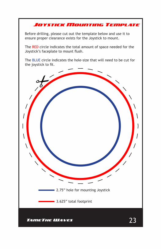
2.75” hole for mounting Joystick
3.625” total footprint
Joystick Mounting Template
Before drilling, please cut out the template below and use it to ensure proper clearance exists for the Joystick to mount. The RED circle indicates the total amount of space needed for the Joystick’s faceplate to mount flush.
The BLUE circle indicates the hole-size that will need to be cut for the joystick to fit.

24
THIS PAGE INTENTIONALLY LEFT BLANK

TameThe Waves 25

26
Warranty
1. It is Customer’s responsibility to make a careful inspection of the Product for evidence of loss or damage, both apparent and concealed. For loss or damage by motor freight, freight forwarders, railway express, rail or air shipments, secure a nota-tion of any loss or damage on Customer’s copy and on the carrier’s copy of the delivery receipt, retain products and shipping containers, and call carrier immediately for an inspection and file a claim with the carrier.
2. To the extent that this order is covered by a prior written contract between the parties, it is accepted on the terms and conditions in that contact and the terms and conditions expressed herein are not intended to modify, change, or supersede such prior contract. To the extent that this order is not covered by such a contract, this instrument contains all of the terms and conditions with respect to the sale and purchase of the Products named herein. Manufacturer can change its applicable terms and conditions at any time unless otherwise explicitly stated on the face hereof or in an effective prior written contract. No modifications of these terms and conditions shall be of any force unless such modification shall be in writing and signed by the party claimed to be bound thereby. If any of the provisions of Customer’s purchase order or other writings are in conflict with the terms and conditions of this document, the terms and conditions of this document shall govern. This sales agreement is not assignable or transferable by Customer, in whole or in part, except with the written consent of Manufacturer.
3. Manufacturer’s liability as to delivery ceases upon making delivery of the Products purchased hereunder to carrier at shipping point in good condition. Title and risk of loss for the Products supplied hereunder will pass at the F.O.B. point specified in Manufacturer’s applicable published price schedule for all Products shipped by Man-ufacturer. Title and risk of loss for all Products picked up by Customer at Manufactur-er’s designated shipping locations will pass to Customer at the point the Products are deposited by Manufacturer onto Customer’s owned or leased equipment.
4. MANUFACTURER MAKES NO WARRANTIES, EXPRESS OR IMPLIED, WITH RE-SPECT TO ITS PRODUCT, WHETHER AS MERCHANTABILITY, FITNESS FOR A PARTICULAR PURPOSE, OR ANY OTHER MATTER EXCEPT THAT ITS PRODUCTS WILL BE FREE FROM DE-FECTS IN MATERIAL AND IN WORKMANSHIP AND WILL CONFORM TO THE SPECIFICATIONS THAT HAVE BEEN PUBLISHED IN WRITING BY MANUFACTURER AND MADE AVAILABLE TO CUSTOMER. THE CUSTOMER ASSUMES ALL RISKS OF LIABILITY WHATSOEVER RESULTING FROM THE USE OF MANUFACTURER’S PRODUCTS WHETHER USED SINGULARLY OR IN COMBINATION WITH OTHER ITEMS. MANUFACTURER’S LIABILITY FOR NONCONFORMING PRODUCTS IS EXCLUSIVELY LIMITED TO THE REPLACEMENT OF THE DEFECTIVE PRODUCTS FOR PERIOD A OF TWO YEARS AFTER THE DATE OF SALE, PROVIDED THE CUSTOMER COMPLIES WITH MANUFACTURER’S CURRENT PUBLISHED RETURN POLICY. UNDER NO CIRCUMSTANCES SHALL MANUFACTURER BE LIABLE FOR INCIDENTAL OR CONSEQUENTIAL DAMAGES. NOTWITHSTANDING ANY OF THE ABOVE TO THE CONTRARY, MANUFACTUR-ER’S MAXIMUM LIABLE SHALL NOT EXCEED THE COST OF THE PRODUCT.
This warranty shall not apply to Products that have been repaired or altered by anyone other than Manufacturer. This Warranty shall not apply to any Products subject to misuse due to common negligence or accident.

TameThe Waves 27
Warranty
Any oral statement concerning the Products inconsistent with this warranty shall be of no force or effect. The only warranties concerning the Products are made in writing by Manufacturer. The Customer may not rely upon any statement or representation concerning the Product made by any other person.
This Warranty is available to the Customer and is not transferable.
5. Customer shall examine any such Products for any damage, defect, or shortage. All claims for any cause whatsoever (whether such cause be based on con-tract, breach of warranty, negligence, strict liability, other tort, or otherwise) shall be deemed waived unless made in writing and received by Manufacturer within thirty days after Customer’s receipt of such Products or before such Products are used, whichever shall occur first, or if such claim is for non-delivery of such Products, within thirty days after the date upon which such Products were to be delivered; provided that as to such claim not reasonably discoverable within such thirty-day period (including such claims discoverable only in processing, further manufacture, other use, or resale), such claim shall be made in writing and received by Manufacturer within 180 days after Custom-er’s receipt of the Products. Failure of Manufacturer to receive written notice of any such claim within the applicable time period shall be deemed an absolute and uncon-ditional waiver by Customer of such claim irrespective of whether the facts giving rise to such claim shall have been discovered or whether processing, further manufacture, other use, or other resale of the Products shall have taken place. Products sold under this Agreement shall not be returned without Manufacturer’s permission and trans-portation charges for return shall not be paid by Manufacturer unless authorized in advance.
6. Payment terms are net thirty (30) days form invoice date unless otherwise agreed in writing. In the event Customer fails to fulfill the terms of payment, or in case Manufacturer shall have any doubt at any time as to Customer’s financial respon-sibility, Manufacturer may decline to make further deliveries except upon receipt of cash or satisfactory security. Past due balances are subject to a late payment charge of 1½% per month, or the maximum amount permitted by applicable law, whichever is less. Customer shall reimburse Manufacturer for all taxes, excise, or other charges which Manufacturer may be required to pay to any government (national, state, or local) upon the sale, production, or transportation of the Products sold hereunder. Customer shall pay all reasonable costs, fees (including attorneys’ fees), and expenses incurred by Manufacturer in collecting monies due or to become due hereunder.
7. It is expressly understood that any technical advice furnished by Manufac-turer with reference to the use of its Products is given gratis and Manufacturer assumes no obligation or liability for the advice given or results obtained. All such advice is given and accepted at Customer’s risk.
8. The agreements between the Manufacturer and Customer were made and entered into by the parties in the State of Minnesota. In the event a dispute arises, said dispute shall be settled in the District Court, Stearns County, Minnesota. The agreement between Manufacturer and Customer shall be construed and interpreted according to the laws of the State of Minnesota.

WWW.PROTRIMTABS.COM Reproduction of this booklet, in whole or in part, without permission is prohibited. All artwork contained within this booklet has been properly licensed by Powrtran Inc. for the sole purpose of this publication. Any images of other company’s products and/or logos is in no way intentional and does not signify any business relationship between said company and Powrtran Inc.