installation and please read operation · pdf fileinstallation and operation guide ......
TRANSCRIPT
LUTRON
Installation and Operation Guide
®
Please Read
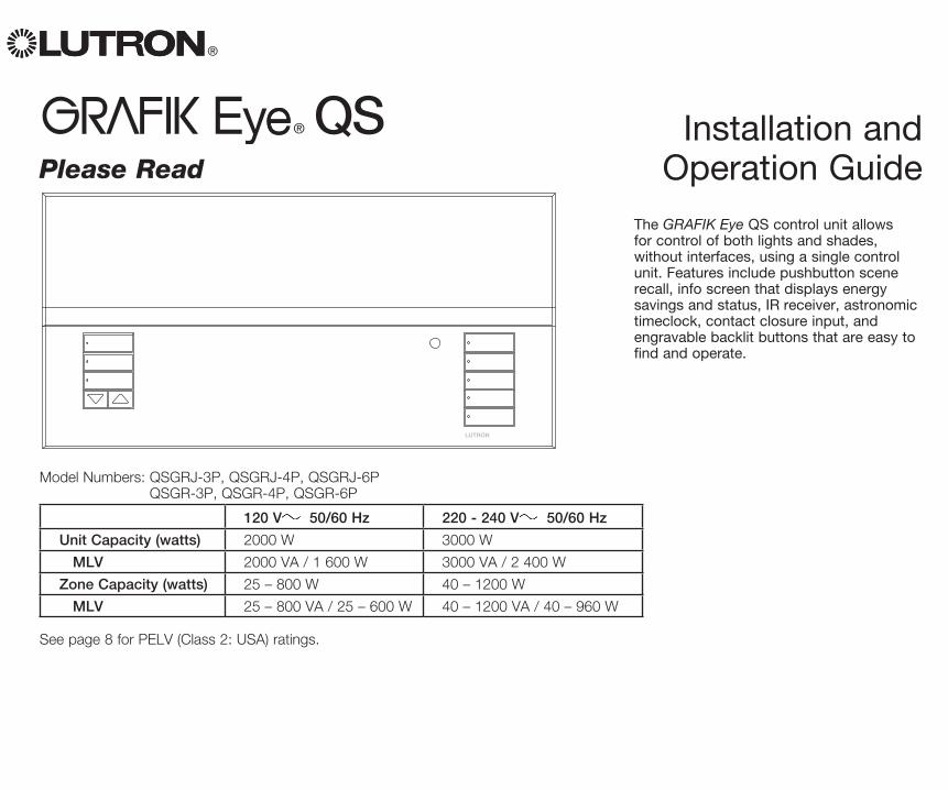
The GRAFIK Eye QS control unit allows for control of both lights and shades, without interfaces, using a single control unit. Features include pushbutton scene recall, info screen that displays energy savings and status, IR receiver, astronomic timeclock, contact closure input, and engravable backlit buttons that are easy to find and operate.
Model Numbers: QSGRJ-3P, QSGRJ-4P, QSGRJ-6P QSGR-3P, QSGR-4P, QSGR-6P
120 V 50/60 Hz 220 - 240 V 50/60 Hz
Unit Capacity (watts) 2000 W 3000 W
MLV 2000 VA / 1 600 W 3000 VA / 2 400 W
Zone Capacity (watts) 25 – 800 W 40 – 1200 W
MLV 25 – 800 VA / 25 – 600 W 40 – 1200 VA / 40 – 960 W
See page 8 for PELV (Class 2: USA) ratings.
® GRAFIK Eye® QS Installation and Operation Guide 2
ContentsFeatures and Functions of the GRAFIK Eye® QS . . . . . . . . . . . . . . . . . . . . . . . . . . . . . . . 3
Wiring the GRAFIK Eye® QSOverview of Line Voltage/Mains Wiring . . . . . . . . . 4Line Voltage Wiring Details . . . . . . . . . . . . . . . . . . . 5Overview of PELV (Class 2: USA) Wiring . . . . . . . . 7QS Link Control Wiring Details . . . . . . . . . . . . . . . . 8QS Link Control Wiring and Terminal Connection Example . . . . . . . . . . . 9Powering More Than 3 Wallstations . . . . . . . . . . 10
Completing Installation of the GRAFIK Eye® QS . . . . . . . . . . . . . . . . . . . . . . . 11
General Functionality . . . . . . . . . . . . . . . . . . . 12
Pre-Programmed Button Functionality . . . . . 13
Zone Button OperationZone LED Displays for % of Lighting Levels . . . . 14
Programming ModeEntering and Exiting Programming Mode . . . . . . 15Navigating Menus in Programming Mode . . . . . . 15
Wireless Mode . . . . . . . . . . . . . . . . . . . . . . . . . 16FCC Information . . . . . . . . . . . . . . . . . . . . . . . . . . 16
Zone SetupAssign Load Types . . . . . . . . . . . . . . . . . . . . . . . . 17Assign Non-Dim Load Type . . . . . . . . . . . . . . . . . 17Setting Load Types . . . . . . . . . . . . . . . . . . . . . . . . 18Set High End or Low End Trim . . . . . . . . . . . . . . . 19Set Minimum Level (optional) . . . . . . . . . . . . . . . . 19Label a Zone (optional) . . . . . . . . . . . . . . . . . . . . . 20
Contact Closure Input (CCI) Mode Setup . . . 21
Associating Wireless Occupancy Sensors and GRAFIK Eye® QS Wireless Control Units . . . . . . . . . . . . . . . . . . . . . . . . . 22
Occupancy Sensor SetupMode Assignment . . . . . . . . . . . . . . . . . . . . . . . . . 23Scene Mode . . . . . . . . . . . . . . . . . . . . . . . . . . . . . 24Zone Mode . . . . . . . . . . . . . . . . . . . . . . . . . . . . . . 25Label an Occupancy Sensor (optional) . . . . . . . . 26Configure Occupancy Sensor Settings . . . . . . . . 27
Associating Wireless Daylight Sensors and GRAFIK Eye® QS Wireless Control Units . . . . . . . . . . . . . . . . . . . . . . . . . 28
Daylight Sensor SetupAssign Sensors . . . . . . . . . . . . . . . . . . . . . . . . . . . 29Label a Daylight Sensor (optional) . . . . . . . . . . . . 30
Scene SetupSet Zone Levels, Fade Rates, and Shade Group Actions . . . . . . . . . . . . . . . . . 31Label a Scene (optional) . . . . . . . . . . . . . . . . . . . . 32Enable/Disable Daylighting per Scene . . . . . . . . . 32
Set Save ModeSave Modes . . . . . . . . . . . . . . . . . . . . . . . . . . . . . . 33
Quick Scene ProgrammingSave by OK Mode . . . . . . . . . . . . . . . . . . . . . . . . . 34
Timeclock OperationSet Time and Date . . . . . . . . . . . . . . . . . . . . . . . . 35Set Location . . . . . . . . . . . . . . . . . . . . . . . . . . . . . 36Set Daylight Saving Time . . . . . . . . . . . . . . . . . . . 36Add an Event . . . . . . . . . . . . . . . . . . . . . . . . . . . . . 37Delete an Event . . . . . . . . . . . . . . . . . . . . . . . . . . . 38View an Event . . . . . . . . . . . . . . . . . . . . . . . . . . . . 38Set a Holiday . . . . . . . . . . . . . . . . . . . . . . . . . . . . . 39View a Holiday . . . . . . . . . . . . . . . . . . . . . . . . . . . . 39Delete a Holiday . . . . . . . . . . . . . . . . . . . . . . . . . . 39Copy a Schedule . . . . . . . . . . . . . . . . . . . . . . . . . . 40Delete a Schedule . . . . . . . . . . . . . . . . . . . . . . . . . 40Afterhours Mode . . . . . . . . . . . . . . . . . . . . . . . . . . 41Set Up Afterhours Mode . . . . . . . . . . . . . . . . . . . . 42End Afterhours Mode . . . . . . . . . . . . . . . . . . . . . . 42
Associating Pico® Wireless Controls and GRAFIK Eye® QS Wireless Control Units
To use the Pico Wireless Control as a Scene Controller . . . . . . . . . . . . . . . . . . . . . . . . . 43To use the Pico Wireless Control as a Zone Controller . . . . . . . . . . . . . . . . . . . . . . . . . . 44
Associating Sivoia® QS Shades/Drapes and GRAFIK Eye® QS Control Units . . . . . . 45
Adjusting Shade Settings Setting Limits . . . . . . . . . . . . . . . . . . . . . . . . . . . . . 46Preset Adjustment: Simple Method . . . . . . . . . . . 47Preset Adjustment: Advanced Method . . . . . . . . 47Name a Group of Shades . . . . . . . . . . . . . . . . . . . 48
Associating Multiple GRAFIK Eye® QS Control Units . . . . . . . . . . . . . . . . . . . . . . . . . 49
Diagnostics and Special SettingsEnable/Disable Timeclock . . . . . . . . . . . . . . . . . . 50Enable/Disable IR Receiver . . . . . . . . . . . . . . . . . 50Enable/Disable Backlighting . . . . . . . . . . . . . . . . . 50Diagnostics . . . . . . . . . . . . . . . . . . . . . . . . . . . . . . 50
Activate System Accessories . . . . . . . . . . . . . 51
Faceplate Removal . . . . . . . . . . . . . . . . . . . . . 51
Language Selection . . . . . . . . . . . . . . . . . . . . 51
Troubleshooting . . . . . . . . . . . . . . . . . . . . . . . 52
Troubleshooting: Wireless Functions . . . . . . . 53
Troubleshooting: Shade Functions . . . . . . . . 54
Warranty . . . . . . . . . . . . . . . . . . . . . . . . . . . . . 55
Contact Information . . . . . . . . . . . . . . . . . . . . 55
OK
1 2 3 4 5 6
® GRAFIK Eye® QS Installation and Operation Guide 3
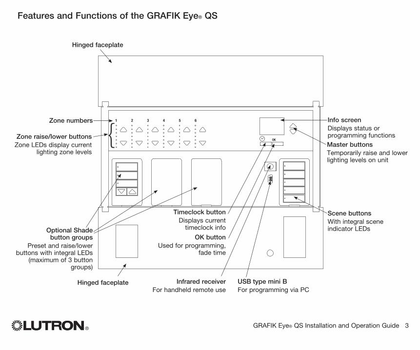
Info screenDisplays status or programming functions
Scene buttonsWith integral scene indicator LEDsOptional Shade
button groupsPreset and raise/lower
buttons with integral LEDs (maximum of 3 button
groups)
Zone numbers
Zone raise/lower buttonsZone LEDs display current
lighting zone levels
Timeclock buttonDisplays current
timeclock info
OK buttonUsed for programming,
fade time
Infrared receiverFor handheld remote use
Master buttonsTemporarily raise and lower lighting levels on unit
USB type mini BFor programming via PC
{
Hinged faceplate
Hinged faceplate
Features and Functions of the GRAFIK Eye® QS
® GRAFIK Eye® QS Installation and Operation Guide 4
12
34
12
AB
C
1 2 3 4 5 6 L N
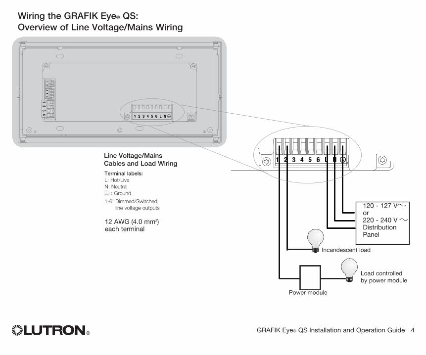
Wiring the GRAFIK Eye® QS:Overview of Line Voltage/Mains Wiring
12 AWG (4.0 mm2) each terminal
120 - 127 V or 220 - 240 V Distribution Panel
Line Voltage/Mains Cables and Load Wiring 1 2 3 4 5 6 L N
Incandescent load
Load controlled by power module
Terminal labels:L: Hot/LiveN: Neutral : Ground
1-6: Dimmed/Switched line voltage outputs
Power module
® GRAFIK Eye® QS Installation and Operation Guide 5
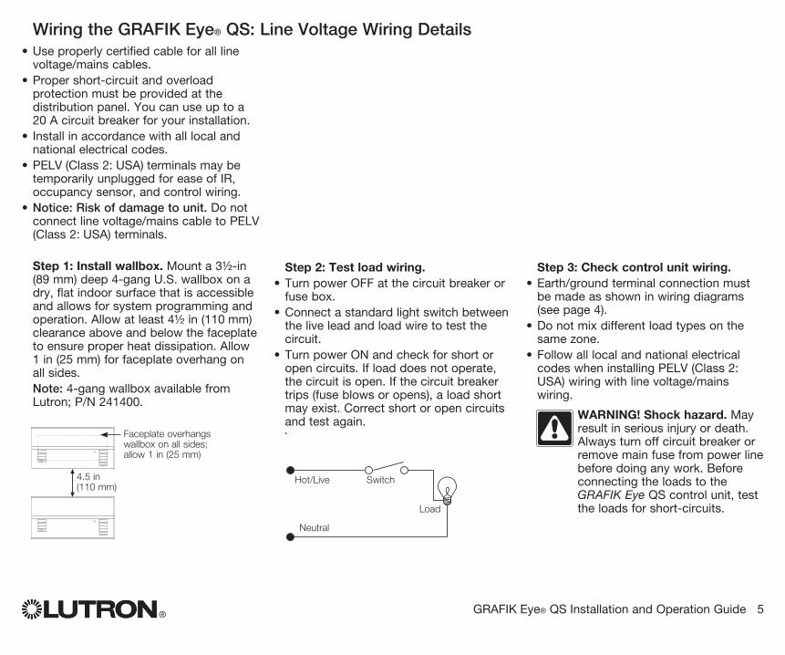
Wiring the GRAFIK Eye® QS: Line Voltage Wiring Details• Use properly certified cable for all line
voltage/mains cables.• Proper short-circuit and overload
protection must be provided at the distribution panel. You can use up to a 20 A circuit breaker for your installation.
• Install in accordance with all local and national electrical codes.
• PELV (Class 2: USA) terminals may be temporarily unplugged for ease of IR, occupancy sensor, and control wiring.
• Notice: Risk of damage to unit . Do not connect line voltage/mains cable to PELV (Class 2: USA) terminals.
Step 1: Install wallbox. Mount a 3½-in (89 mm) deep 4-gang U.S. wallbox on a dry, flat indoor surface that is accessible and allows for system programming and operation. Allow at least 4½ in (110 mm) clearance above and below the faceplate to ensure proper heat dissipation. Allow 1 in (25 mm) for faceplate overhang on all sides. Note: 4-gang wallbox available from Lutron; P/N 241400.
Step 2: Test load wiring.• Turn power OFF at the circuit breaker or
fuse box.• Connect a standard light switch between
the live lead and load wire to test the circuit.
• Turn power ON and check for short or open circuits. If load does not operate, the circuit is open. If the circuit breaker trips (fuse blows or opens), a load short may exist. Correct short or open circuits and test again.`
Step 3: Check control unit wiring.• Earth/ground terminal connection must
be made as shown in wiring diagrams (see page 4).
• Do not mix different load types on the same zone.
• Follow all local and national electrical codes when installing PELV (Class 2: USA) wiring with line voltage/mains wiring.
WARNING! Shock hazard. May result in serious injury or death. Always turn off circuit breaker or remove main fuse from power line before doing any work. Before connecting the loads to the GRAFIK Eye QS control unit, test the loads for short-circuits.
Neutral
Hot/Live Switch
Load
LUTRON
LUTRON
Faceplate overhangs wallbox on all sides; allow 1 in (25 mm)
4.5 in (110 mm)
® GRAFIK Eye® QS Installation and Operation Guide 6
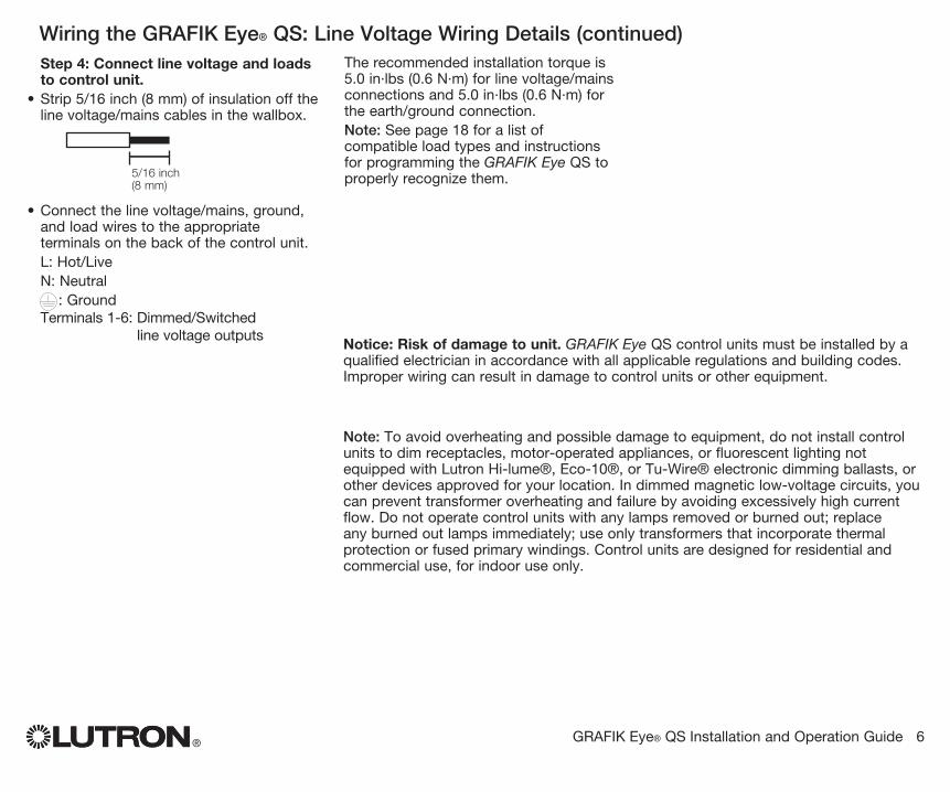
Wiring the GRAFIK Eye® QS: Line Voltage Wiring Details (continued)Step 4: Connect line voltage and loads to control unit.
• Strip 5/16 inch (8 mm) of insulation off the line voltage/mains cables in the wallbox.
• Connect the line voltage/mains, ground, and load wires to the appropriate terminals on the back of the control unit.
L: Hot/Live N: Neutral : Ground Terminals 1-6: Dimmed/Switched
line voltage outputs
5/16 inch (8 mm)
The recommended installation torque is 5.0 in∙lbs (0.6 N∙m) for line voltage/mains connections and 5.0 in∙lbs (0.6 N∙m) for the earth/ground connection.
Note: See page 18 for a list of compatible load types and instructions for programming the GRAFIK Eye QS to properly recognize them.
Notice: Risk of damage to unit. GRAFIK Eye QS control units must be in stalled by a qual i fied electrician in accordance with all applica ble reg u la tions and building codes. Im prop er wiring can result in dam age to control units or oth er equipment.
Note: To avoid over heat ing and pos si ble damage to equipment, do not install control units to dim re cep ta cles, mo tor-op erated ap pli ances, or flu o res cent lighting not equipped with Lutron Hi-lume®, Eco-10®, or Tu-Wire® electronic dim ming ballasts, or other devices approved for your location. In dimmed magnet ic low-voltage cir cuits, you can pre vent trans former overheating and failure by avoid ing excessively high current flow. Do not op erate control units with any lamps re moved or burned out; re place any burned out lamps immediate ly; use only transform ers that in cor po rate ther mal pro tection or fused pri ma ry wind ings. Control units are de signed for res i den tial and commercial use, for indoor use only.
12
34
12
AB
C
1 2 3 4 5 6 L N
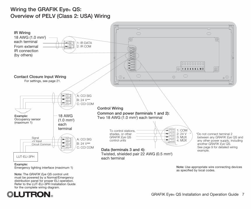
Contact Closure Input Wiring For settings, see page 21.
® GRAFIK Eye® QS Installation and Operation Guide 7
12
AB
C
N H 1 2 3 4 5 6
12
34
12
34
12
AB
C
1 2 3 4 5 6 L N
12
34
12
AB
C
1 2 3 4 5 6 L N
Note: Use appropriate wire connecting devices as specified by local codes.
Example: Occupancy sensor(maximum 1)
1: COM2: 24 V *3: MUX4: MUX
Control Wiring
Wiring the GRAFIK Eye® QS:Overview of PELV (Class 2: USA) Wiring
IR Wiring
From external IR connection (by others)
18 AWG (1.0 mm2) each terminal
18 AWG (1.0 mm2) each terminal
1: IR DATA2: IR COM
A: CCI SIGB: 24 VC: CCI COM
To control stations, shades, or other GRAFIK Eye QS control units
Data (terminals 3 and 4): Twisted, shielded pair 22 AWG (0.5 mm2) each terminal
Common and power (terminals 1 and 2): Two 18 AWG (1.0 mm2) each terminal
* Do not connect terminal 2 between any GRAFIK Eye QS and any other power supply, including another GRAFIK Eye QS.See page 9 for detailed wiring example.1
23
41
2A
BC
1 2 3 4 5 6 L NExample: Emergency lighting interface (maximum 1)
Note: The GRAFIK Eye QS control unit must be powered by a Normal/Emergency distribution panel for proper ELI operation. Refer to the LUT-ELI-3PH Installation Guide for the complete wiring diagram.
A: CCI SIGB: 24 VC: CCI COM
LUT-ELI-3PH
Signal+V InputCircuit Common
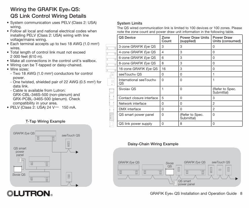
• System communication uses PELV (Class 2: USA) wiring.
• Follow all local and national electrical codes when installing PELV (Class 2: USA) wiring with line voltage/mains wiring.
• Each terminal accepts up to two 18 AWG (1.0 mm2) wires.
• Total length of control link must not exceed 2 000 feet (610 m).
• Make all connections in the control unit’s wallbox.• Wiring can be T-tapped or daisy-chained.• Wire sizes: - Two 18 AWG (1.0 mm2) conductors for control
power. - One twisted, shielded pair of 22 AWG (0.5 mm2) for
data link. - Cable is available from Lutron:
GRX-CBL-346S-500 (non-plenum) and GRX-PCBL-346S-500 (plenum). Check compatibility in your area.
• PELV (Class 2: USA) 24 V 150 mA.
® GRAFIK Eye® QS Installation and Operation Guide 8
QS smart power panel
LUTRON
LUTRON
LUTRON
LUTRONLUTRON
LUTRON
LUTRON
LUTRON
LUTRON
LUTRON
LUTRON
LUTRON
T-Tap Wiring Example
GRAFIK Eye QS
Sivoia QS
seeTouch QS
Wiring the GRAFIK Eye® QS:QS Link Control Wiring Details
System Limits The QS wired communication link is limited to 100 devices or 100 zones. Please
note the zone count and power draw unit information in the following table.
QS Device Zone Count
Power Draw Units (supplied)
Power Draw Units (consumed)
3-zone GRAFIK Eye QS 3 3 0
4-zone GRAFIK Eye QS 4 3 0
6-zone GRAFIK Eye QS 6 3 0
8-zone GRAFIK Eye QS 8 3 0
16-zone GRAFIK Eye QS 16 3 0
seeTouch® QS 0 0 1
International seeTouch® QS
0 0 1
Sivoia® QS 1 0 (Refer to Spec. Submittal)
Contact closure interface 5 0 3
Network interface 0 0 2
DMX interface 0 0 2
QS smart power panel 0 (Refer to Spec. Submittal)
0
QS link power supply 0 8 0
LUTRON
LUTRON
LUTRON
LUTRONLUTRON
LUTRON
LUTRON
LUTRON
LUTRON
LUTRON
LUTRON LUTRON LUTRON
LUTRON
LUTRON
LUTRON
LUTRON
LUTRONLUTRON
LUTRON
LUTRON
LUTRON
LUTRON
LUTRON
LUTRON LUTRON LUTRON
LUTRON
LUTRON
LUTRON
LUTRON
LUTRONLUTRON
LUTRON
LUTRON
LUTRON
LUTRON
LUTRON
LUTRON LUTRON LUTRON
LUTRON
LUTRON
LUTRON
LUTRON
LUTRONLUTRON
LUTRON
LUTRON
LUTRON
LUTRON
LUTRON
LUTRON LUTRON LUTRON
LUTRON
5.26
4.263.75
2.50
1.06
5.26
4.263.75
2.50
1.06
LUTRON
LUTRON
LUTRON
LUTRONLUTRON
LUTRON
LUTRON
LUTRON
LUTRON
LUTRON
LUTRON
LUTRON
GRAFIK Eye QS Sivoia QS
seeTouch QS
Daisy-Chain Wiring Example
QS smart power panel
GRAFIK Eye QS
LUTRON
LUTRON
LUTRON
LUTRONLUTRON
LUTRON
LUTRON
LUTRON
LUTRON
LUTRON
LUTRON LUTRON LUTRON
LUTRON
5.26
4.263.75
2.50
1.06
LUTRON
LUTRON
LUTRON
LUTRONLUTRON
LUTRON
LUTRON
LUTRON
LUTRON
LUTRON
LUTRON LUTRON LUTRON
LUTRON
LUTRON
LUTRON
LUTRON
LUTRONLUTRON
LUTRON
LUTRON
LUTRON
LUTRON
LUTRON
LUTRON LUTRON LUTRON
LUTRON
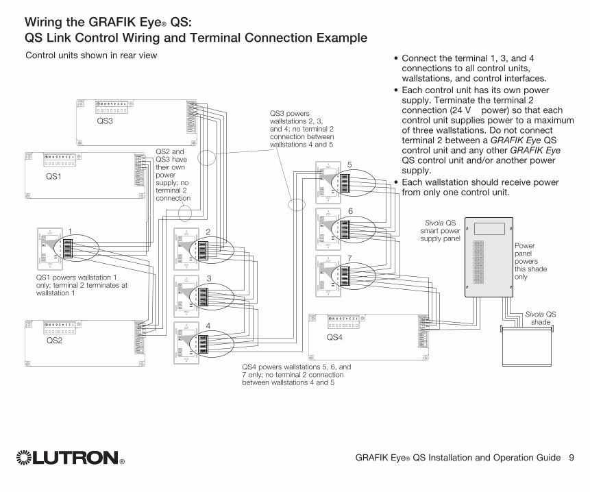
Wiring the GRAFIK Eye® QS:QS Link Control Wiring and Terminal Connection Example
® GRAFIK Eye® QS Installation and Operation Guide 9
4
3
2
1
4
3
2
1
4
3
2
1
4
3
2
1
4
3
2
1
4
3
2
1
4
3
2
1
12
34
12
AB
C
123456HN
12
34
12
AB
C
123456HN
12
34
12
AB
C
123456HN
12
34
12
AB
C
123456HN
2
3
4
1
QS1 powers wallstation 1 only; terminal 2 terminates at wallstation 1
QS2 and QS3 have their own power supply; no terminal 2 connection
QS3 powers wallstations 2, 3, and 4; no terminal 2 connection betweenwallstations 4 and 5
QS4 powers wallstations 5, 6, and 7 only; no terminal 2 connection between wallstations 4 and 5
Power panel powers this shade only
Sivoia QS shade
Sivoia QS smart power supply panel
Control units shown in rear view
5
6
7
• Connect the terminal 1, 3, and 4 connections to all control units, wallstations, and control interfaces.
• Each control unit has its own power supply. Terminate the terminal 2 connection (24 V power) so that each control unit supplies power to a maximum of three wallstations. Do not connect terminal 2 between a GRAFIK Eye QS control unit and any other GRAFIK Eye QS control unit and/or another power supply.
• Each wallstation should receive power from only one control unit.
QS3
QS1
QS2 QS4
® GRAFIK Eye® QS Installation and Operation Guide 10
12
34
12
AB
C
4321
4321
4321
4321
123456LN
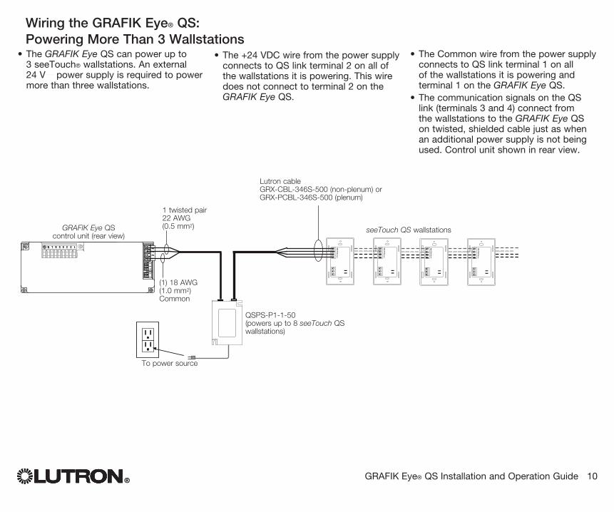
Wiring the GRAFIK Eye® QS: Powering More Than 3 Wallstations
®
• The +24 VDC wire from the power supply connects to QS link terminal 2 on all of the wallstations it is powering. This wire does not connect to terminal 2 on the GRAFIK Eye QS.
• The GRAFIK Eye QS can power up to 3 seeTouch® wallstations. An external 24 V power supply is required to power more than three wallstations.
To power source
QSPS-P1-1-50 (powers up to 8 seeTouch QS wallstations)
• The Common wire from the power supply connects to QS link terminal 1 on all of the wallstations it is powering and terminal 1 on the GRAFIK Eye QS.
• The communication signals on the QS link (terminals 3 and 4) connect from the wallstations to the GRAFIK Eye QS on twisted, shielded cable just as when an additional power supply is not being used. Control unit shown in rear view.
GRAFIK Eye QS control unit (rear view)
1 twisted pair22 AWG (0.5 mm2)
Lutron cableGRX-CBL-346S-500 (non-plenum) or GRX-PCBL-346S-500 (plenum)
seeTouch QS wallstations
(1) 18 AWG (1.0 mm2)Common
® GRAFIK Eye® QS Installation and Operation Guide 11
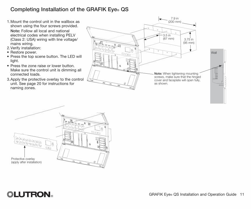
Completing Installation of the GRAFIK Eye® QS
1. Mount the control unit in the wallbox as shown using the four screws pro vid ed.Note: Follow all local and national electrical codes when installing PELV (Class 2: USA) wiring with line voltage/mains wiring.
2. Verify installation:• Restore power.• Press the top scene button. The LED will
light.• Press the zone raise or lower button.
Make sure the control unit is dimming all connected loads.
3. Apply the protective overlay to the control unit. See page 20 for instructions for naming zones.
Note: When tightening mounting screws, make sure that the hinged cover and faceplate will open fully, as shown.
Wall
7.9 in (200 mm)
3.5 in (87 mm) 3.75 in
(95 mm)
Protective overlay (apply after installation)
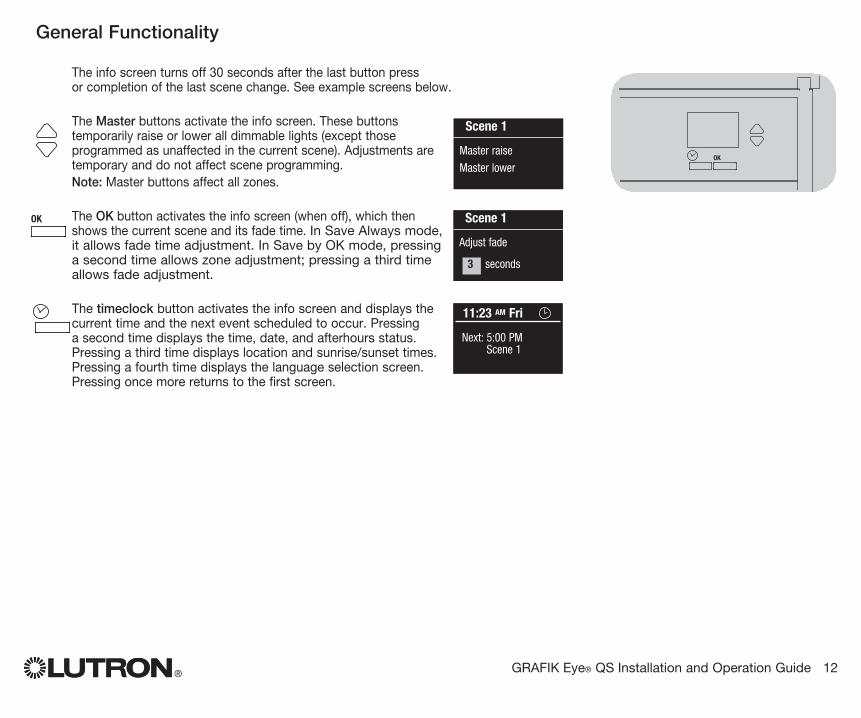
The info screen turns off 30 seconds after the last button press or completion of the last scene change. See example screens below.
The Master buttons activate the info screen. These buttons temporarily raise or lower all dimmable lights (except those programmed as unaffected in the current scene). Adjustments are temporary and do not affect scene programming.Note: Master buttons affect all zones.
The OK button activates the info screen (when off), which then shows the current scene and its fade time. In Save Always mode, it allows fade time adjustment. In Save by OK mode, pressing a second time allows zone adjustment; pressing a third time allows fade adjustment.
The timeclock button activates the info screen and displays the current time and the next event scheduled to occur. Pressing a second time displays the time, date, and afterhours status. Pressing a third time displays location and sunrise/sunset times. Pressing a fourth time displays the language selection screen. Pressing once more returns to the first screen.
® GRAFIK Eye® QS Installation and Operation Guide 12
OK
1 2 3 4 5 6Scene 1
Master raise
Master lower
General Functionality
OK
1 2 3 4 5 6
OK
1 2 3 4 5 6
OK
1 2 3 4 5 6
Scene 1
Adjust fade
3 seconds
11:23 AM Fri
Next: 5:00 PM Scene 1
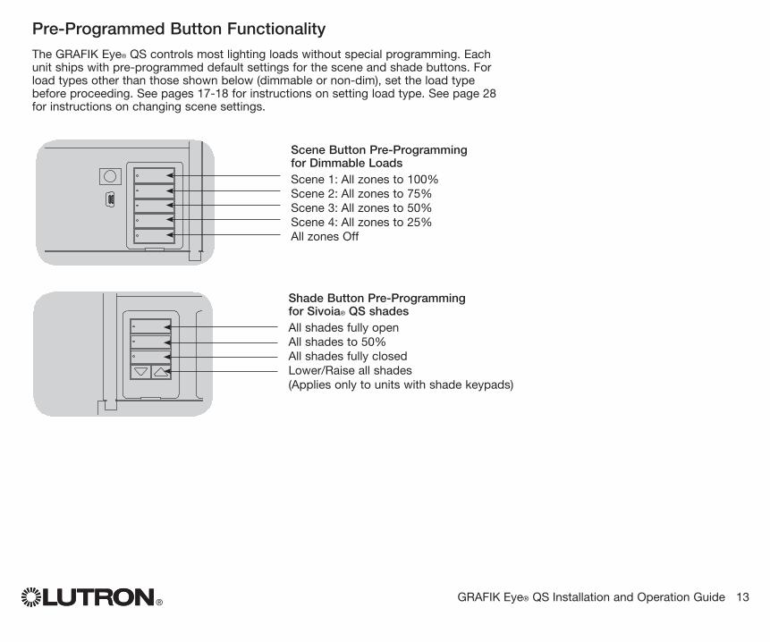
Pre-Programmed Button Functionality
® GRAFIK Eye® QS Installation and Operation Guide 13
OK
1 2 3 4 5 6
Scene Button Pre-Programming for Dimmable LoadsScene 1: All zones to 100%Scene 2: All zones to 75%Scene 3: All zones to 50%Scene 4: All zones to 25%All zones Off
OK
1 2 3 4 5 6
Shade Button Pre-Programming for Sivoia® QS shadesAll shades fully openAll shades to 50%All shades fully closedLower/Raise all shades(Applies only to units with shade keypads)
The GRAFIK Eye® QS controls most lighting loads without special programming. Each unit ships with pre-programmed default settings for the scene and shade buttons. For load types other than those shown below (dimmable or non-dim), set the load type before proceeding. See pages 17-18 for instructions on setting load type. See page 28 for instructions on changing scene settings.
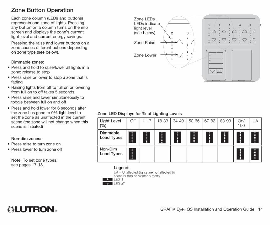
Zone Button OperationEach zone column (LEDs and buttons) represents one zone of lights. Pressing any button on a column turns on the info screen and displays the zone’s current light level and current energy savings.
Pressing the raise and lower buttons on a zone causes different actions depending on zone type (see below).
Dimmable zones:• Press and hold to raise/lower all lights in a
zone; release to stop• Press raise or lower to stop a zone that is
fading• Raising lights from off to full on or lowering
from full on to off takes 5 seconds• Press raise and lower simultaneously to
toggle between full on and off
• Press and hold lower for 6 seconds after the zone has gone to 0% light level to set the zone as unaffected in the current scene (the zone will not change when this scene is initiated)
Non-dim zones:• Press raise to turn zone on• Press lower to turn zone off
Note: To set zone types, see pages 17-18.
® GRAFIK Eye® QS Installation and Operation Guide 14
OK
1 2 3 4 5 6
OK
1 2 3 4 5 6
Zone Raise
Zone Lower
Legend: UA = Unaffected (lights are not affected by
scene button or Master buttons) LED lit LED off
Zone LEDsLEDs indicate light level (see below)
Zone LED Displays for % of Lighting Levels
Light Level (%)
Off 1–17 18-33 34-49 50-66 67-82 83-99 On/ 100
UA
Dimmable Load Types
Non-Dim Load Types
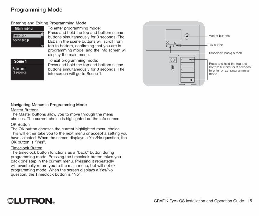
Entering and Exiting Programming ModeTo enter programming mode:Press and hold the top and bottom scene buttons simultaneously for 3 seconds. The LEDs in the scene buttons will scroll from top to bottom, confirming that you are in programming mode, and the info screen will display the main menu.
To exit programming mode:Press and hold the top and bottom scene buttons simultaneously for 3 seconds. The info screen will go to Scene 1.
Navigating Menus in Programming ModeMaster ButtonsThe Master buttons allow you to move through the menu choices. The current choice is highlighted on the info screen.
OK ButtonThe OK button chooses the current highlighted menu choice. This will either take you to the next menu or accept a setting you have selected. When the screen displays a Yes/No question, the OK button is “Yes”.
Timeclock ButtonThe timeclock button functions as a “back” button during programming mode. Pressing the timeclock button takes you back one step in the current menu. Pressing it repeatedly will eventually return you to the main menu, but will not exit programming mode. When the screen displays a Yes/No question, the Timeclock button is “No”.
® GRAFIK Eye® QS Installation and Operation Guide 15
Programming Mode
OK
1 2 3 4 5 6
Press and hold the top and bottom buttons for 3 seconds to enter or exit programming mode
Master buttons
OK button
Timeclock (back) button
Main menu
Scene setupTimeclock
Scene 1
Fade time 3 seconds
® GRAFIK Eye® QS Installation and Operation Guide 16
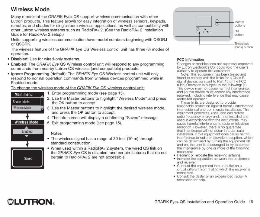
Wireless Mode Many models of the GRAFIK Eye® QS support wireless communication with other
Lutron products. This feature allows for easy integration of wireless sensors, keypads, remotes, and shades for single-room wireless applications, as well as compatibility with other Lutron wireless systems such as RadioRA® 2. (See the RadioRA® 2 Installation Guide for RadioRA® 2 setup.)
Units supporting wireless communication have model numbers beginning with QSGRJ or QSGRK.
The wireless feature of the GRAFIK Eye QS Wireless control unit has three (3) modes of operation.
• Disabled: Use for wired-only systems.• Enabled: The GRAFIK Eye QS Wireless control unit will respond to any programming
commands from nearby Lutron QS wireless (and compatible) products.• Ignore Programming (default): The GRAFIK Eye QS Wireless control unit will only
respond to normal operation commands from wireless devices programmed while in Enabled mode.
To change the wireless mode of the GRAFIK Eye QS wireless control unit:1. Enter programming mode (see page 15).2. Use the Master buttons to highlight “Wireless Mode” and press
the OK button to accept.3. Use the Master buttons to highlight the desired wireless mode,
and press the OK button to accept.4. The info screen will display a confirming “Saved” message.5. Exit programming mode (see page 15).
Notes• The wireless signal has a range of 30 feet (10 m) through
standard construction.• When used within a RadioRA® 2 system, the wired QS link on
the GRAFIK Eye QS is disabled, and certain features that do not pertain to RadioRA® 2 are not accessible.
Wireless Mode
Enabled
SavedSaved
Main menu
Shade labels
Wireless Mode
FCC InformationChanges or modifications not expressly approved by Lutron Electronics Co. could void the user’s authority to operate this equipment. Note: This equipment has been tested and found to comply with the limits for a Class B digital device, pursuant to Part 15 of the FCC rules. Operation is subject to the following: (1) This device may not cause harmful interference, and (2) this device must accept any interference received, including interference that may cause undesired operation. These limits are designed to provide reasonable protection against harmful interference in a residential and commercial installation. This equipment generates, uses, and can radiate radio frequency energy and, if not installed and used in accordance with the instructions, may cause harmful interference to radio or television reception. However, there is no guarantee that interference will not occur in a particular installation. If this equipment does cause harmful interference to radio or television reception, which can be determined by turning the equipment off and on, the user is encouraged to try to correct the interference by one or more of the following measures:
• Reorient or relocate the receiving antenna.• Increase the separation between the equipment
and receiver.• Connect the equipment into an outlet on a
circuit different from that to which the receiver is connected.
• Consult the dealer or an experienced radio/TV technician for help.
OK
1 2 3 4 5 6
Master buttons
OK button
Timeclock (back) button
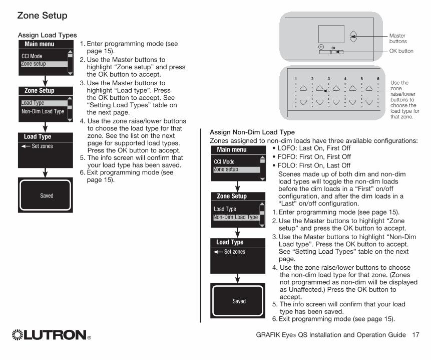
® GRAFIK Eye® QS Installation and Operation Guide 17
Assign Load Types1. Enter programming mode (see
page 15).2. Use the Master buttons to
highlight “Zone setup” and press the OK button to accept.
3. Use the Master buttons to highlight “Load type”. Press the OK button to accept. See “Setting Load Types” table on the next page.
4. Use the zone raise/lower buttons to choose the load type for that zone. See the list on the next page for supported load types. Press the OK button to accept.
5. The info screen will confirm that your load type has been saved.
6. Exit programming mode (see page 15).
Zone Setup
OK
1 2 3 4 5 6
Master buttons
OK buttonMain menu
CCI ModeZone setup
OK
1 2 3 4 5 6Use the zone raise/lower buttons to choose the load type for that zone.
Zone Setup
Non-Dim Load Type
Load Type Set zones
Saved
Load Type
Assign Non-Dim Load TypeZones assigned to non-dim loads have three available configurations:
• LOFO: Last On, First Off• FOFO: First On, First Off• FOLO: First On, Last Off Scenes made up of both dim and non-dim
load types will toggle the non-dim loads before the dim loads in a “First” on/off configuration, and after the dim loads in a “Last” on/off configuration.
1. Enter programming mode (see page 15).2. Use the Master buttons to highlight “Zone
setup” and press the OK button to accept.3. Use the Master buttons to highlight “Non-Dim
Load type”. Press the OK button to accept. See “Setting Load Types” table on the next page.
4. Use the zone raise/lower buttons to choose the non-dim load type for that zone. (Zones not programmed as non-dim will be displayed as Unaffected.) Press the OK button to accept.
5. The info screen will confirm that your load type has been saved.
6. Exit programming mode (see page 15).
Main menu
CCI ModeZone setup
Zone Setup
Load Type
Load Type Set zones
Saved
Non-Dim Load Type
® GRAFIK Eye® QS Installation and Operation Guide 18
Zone Setup (continued)
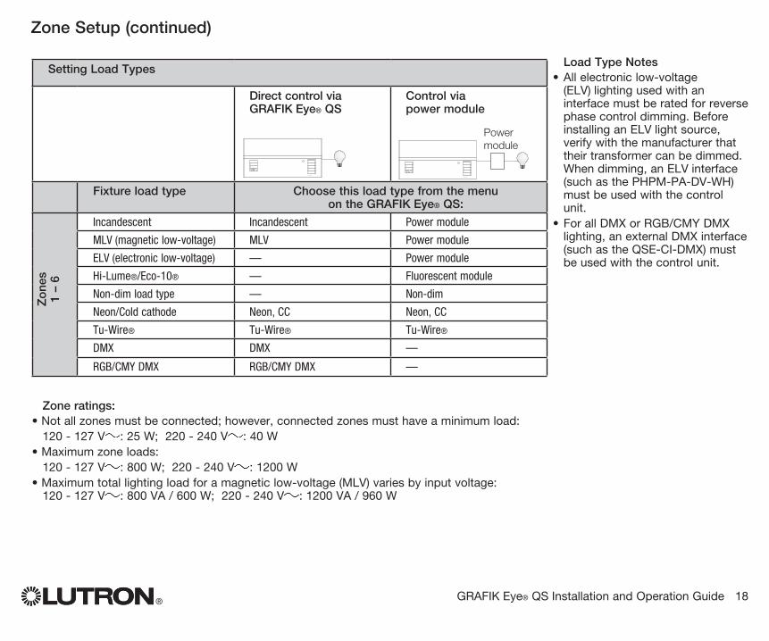
Load Type Notes• All electronic low-voltage
(ELV) lighting used with an interface must be rated for reverse phase control dimming. Before installing an ELV light source, verify with the manufacturer that their transformer can be dimmed. When dimming, an ELV interface (such as the PHPM-PA-DV-WH) must be used with the control unit.
• For all DMX or RGB/CMY DMX lighting, an external DMX interface (such as the QSE-CI-DMX) must be used with the control unit.
LUTRON
LUTRON
LUTRON
LUTRON
Setting Load Types
Direct control via GRAFIK Eye® QS
Control via power module
Fixture load type Choose this load type from the menu on the GRAFIK Eye® QS:
Zo
nes
1
– 6
Incandescent Incandescent Power module
MLV (magnetic low-voltage) MLV Power module
ELV (electronic low-voltage) — Power module
Hi-Lume®/Eco-10® — Fluorescent module
Non-dim load type — Non-dim
Neon/Cold cathode Neon, CC Neon, CC
Tu-Wire® Tu-Wire® Tu-Wire®
DMX DMX —
RGB/CMY DMX RGB/CMY DMX —
Zone ratings:• Not all zones must be connected; however, connected zones must have a minimum load: 120 - 127 V : 25 W; 220 - 240 V : 40 W• Maximum zone loads: 120 - 127 V : 800 W; 220 - 240 V : 1200 W• Maximum total lighting load for a magnetic low-voltage (MLV) varies by input voltage:
120 - 127 V : 800 VA / 600 W; 220 - 240 V : 1200 VA / 960 W
Power module
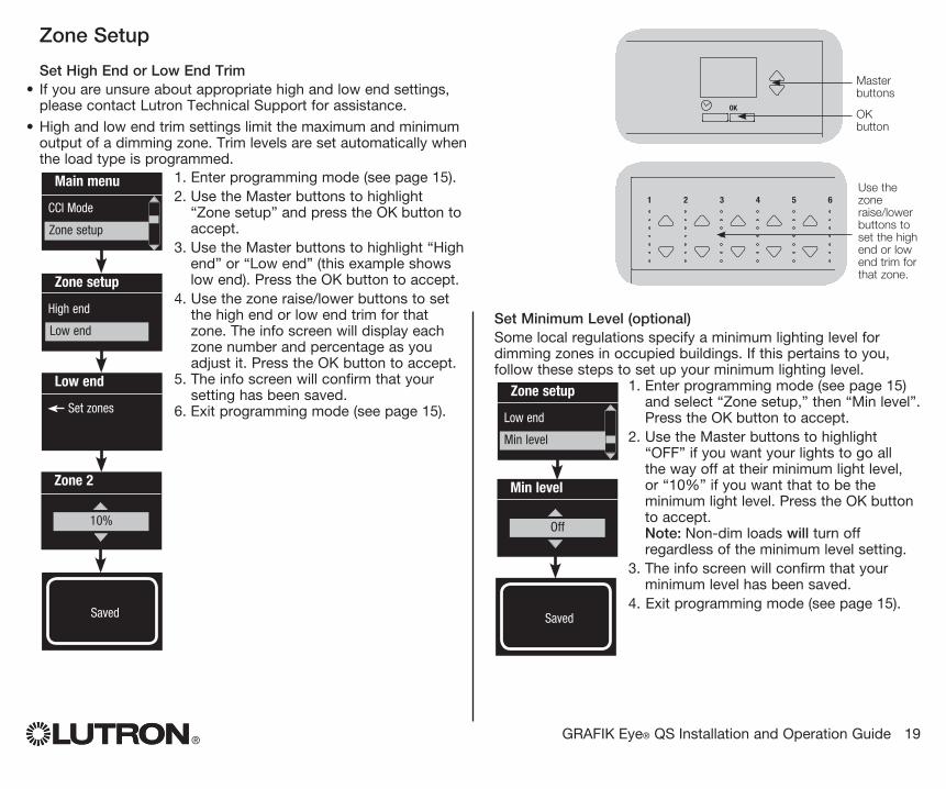
Set Minimum Level (optional)Some local regulations specify a minimum lighting level for dimming zones in occupied buildings. If this pertains to you, follow these steps to set up your minimum lighting level.
1. Enter programming mode (see page 15) and select “Zone setup,” then “Min level”. Press the OK button to accept.
2. Use the Master buttons to highlight “OFF” if you want your lights to go all the way off at their minimum light level, or “10%” if you want that to be the minimum light level. Press the OK button to accept. Note: Non-dim loads will turn off regardless of the minimum level setting.
3. The info screen will confirm that your minimum level has been saved.
4. Exit programming mode (see page 15).
® GRAFIK Eye® QS Installation and Operation Guide 19
Zone Setup
Set High End or Low End Trim• If you are unsure about appropriate high and low end settings,
please contact Lutron Technical Support for assistance.
• High and low end trim settings limit the maximum and minimum output of a dimming zone. Trim levels are set automatically when the load type is programmed.
1. Enter programming mode (see page 15).2. Use the Master buttons to highlight
“Zone setup” and press the OK button to accept.
3. Use the Master buttons to highlight “High end” or “Low end” (this example shows low end). Press the OK button to accept.
4. Use the zone raise/lower buttons to set the high end or low end trim for that zone. The info screen will display each zone number and percentage as you adjust it. Press the OK button to accept.
5. The info screen will confirm that your setting has been saved.
6. Exit programming mode (see page 15).
Main menu
CCI Mode
Zone setup
High end
Zone 2
Low end
Set zones
Low end
OK
1 2 3 4 5 6
Master buttons
OK
1 2 3 4 5 6Use the zone raise/lower buttons to set the high end or low end trim for that zone.
OK button
10%
Min level
Off
Zone setup
Low end
Min level
Zone setup
Saved Saved
® GRAFIK Eye® QS Installation and Operation Guide 20
Zone Setup
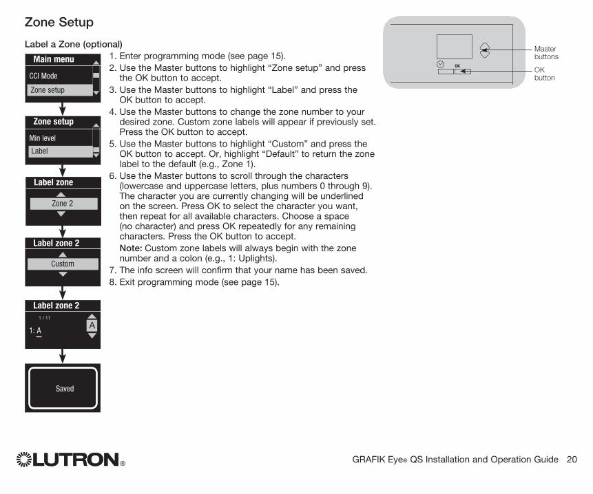
Label a Zone (optional)1. Enter programming mode (see page 15).2. Use the Master buttons to highlight “Zone setup” and press
the OK button to accept.3. Use the Master buttons to highlight “Label” and press the
OK button to accept.4. Use the Master buttons to change the zone number to your
desired zone. Custom zone labels will appear if previously set. Press the OK button to accept.
5. Use the Master buttons to highlight “Custom” and press the OK button to accept. Or, highlight “Default” to return the zone label to the default (e.g., Zone 1).
6. Use the Master buttons to scroll through the characters (lowercase and uppercase letters, plus numbers 0 through 9). The character you are currently changing will be underlined on the screen. Press OK to select the character you want, then repeat for all available characters. Choose a space (no character) and press OK repeatedly for any remaining characters. Press the OK button to accept.
Note: Custom zone labels will always begin with the zone number and a colon (e.g., 1: Uplights).
7. The info screen will confirm that your name has been saved.8. Exit programming mode (see page 15).
Main menu
CCI Mode
Zone setup
Min level
Label zone
Label
Label zone 2
Custom
Label zone 2
1: AA
1 / 11
OK
1 2 3 4 5 6
Master buttons
OK button
Zone setup
Zone 2
Saved

® GRAFIK Eye® QS Installation and Operation Guide 21
Contact Closure Input (CCI) Mode Setup(wired directly to the GRAFIK Eye® QS)
The integral contact closure input (CCI) on the back of the GRAFIK Eye® QS can be configured to match the installation requirements. The choices are listed and explained below. (See page 7 for wiring details.)
To change the operation of the contact closure input:
1. Enter programming mode (see page 15).2. Use the Master buttons to highlight “CCI Mode” and press the
OK button to accept.3. Use the Master buttons to highlight the mode you wish the
CCI to control. Press the OK button to accept.4. The info screen will confirm that your setting has been saved.5. Exit programming mode (see page 15).
CCI Mode Settings Occupancy: Allows a wired occupancy sensor to be included
in the list of available sensors when setting up occupancy actions.
Emergency: This setting allows the GRAFIK Eye QS to work with a LUT-ELI-3PH emergency lighting interface. When an emergency situation is detected, all lights will go to full on, and no operations will be allowed until the emergency signal is cleared.
Afterhours: Allows the CCI to start and end the afterhours mode.
Timeclock: Allows the CCI to enable and disable the timeclock. Lockout: Prevents the user from making any changes to
the control unit. The current scene will stay on until the CCI enables normal operation.
Never Save: Prevents any changes from being saved while the CCI is being used.
Disable CCI: The CCI will have no effect on the system and will not appear on the list of available occupancy sensors within the sensor setup menu.
CCI Mode
Occupancy
SavedSaved
Main menu
Save Mode
CCI Mode
OK
1 2 3 4 5 6
Master buttons
OK button
Timeclock (back) button

® GRAFIK Eye® QS Installation and Operation Guide 22
OK
1 2 3 4 5 6
Wireless Occupancy Sensor“Talks” to GRAFIK Eye QS control unit, activating scenes on the GRAFIK Eye QS.
Lutron’s wireless Radio Powr SavrTM occupancy and vacancy sensors can be associated with the GRAFIK Eye QS Wireless to activate scenes when occupancy or vacancy is detected.This section applies to installations where the GRAFIK Eye QS Wireless is being used in a single-room wireless installation. Refer to the RadioRA® 2 installation guide for setting up occupancy and vacancy sensors in a RadioRA® 2 system.
To associate wireless occupancy sensors and GRAFIK Eye QS control units:1. Make sure the wireless mode of the GRAFIK Eye QS control unit is
“Enabled” (see page 16).2. Press and hold the “Lights On” and “Lights Off” buttons on the front of
the occupancy/vacancy sensor simultaneously until the lens starts flashing (about 3 seconds). The info screen on the GRAFIK Eye QS will display “Occ Sensor Programming.”
3. Press and hold the top scene button of the GRAFIK Eye QS Wireless control unit until the LEDs flash (about 3 seconds).
4. Return to the occupancy sensor. Press and hold the “Lights On” and “Lights Off” buttons simultaneously until the lens stops flashing (about 3 seconds).
5. Test communication between the devices using the “Lights On” and “Lights Off” buttons.
To disassociate wireless occupancy sensors and GRAFIK Eye control units:Simply repeat the association steps, in the same order; press and hold the bottom scene button on the GRAFIK Eye QS to disassociate.
Note: The wireless signal has a range of 30 feet (10 m) through standard construction.
Associating Wireless Occupancy Sensors and GRAFIK Eye® QS Wireless Control Units (for wireless enabled units only)
On the wireless occupancy sensor, press and hold the “Lights On” and “Lights Off” buttons for 3 seconds to begin or end association or disassociation with the GRAFIK Eye QS control unit.
Note: Pressing the “Lights On” button initiates the “occupied” action on the GRAFIK Eye QS control unit. Pressing the “Lights Off” button initiates the “unoccupied” action.
OK
1 2 3 4 5 6
On the GRAFIK Eye QS control unit, press and hold the top scene button for 3 seconds to associate, or press and hold the bottom scene button for 3 seconds to disassociate with the occupancy sensor.
Associate
OR
Disassociate
GRAFIK Eye QS Control Unit“Listens” to wireless occupancy sensor, so that the occupancy sensor activates scenes on the GRAFIK Eye QS.
Lens
® GRAFIK Eye® QS Installation and Operation Guide 23
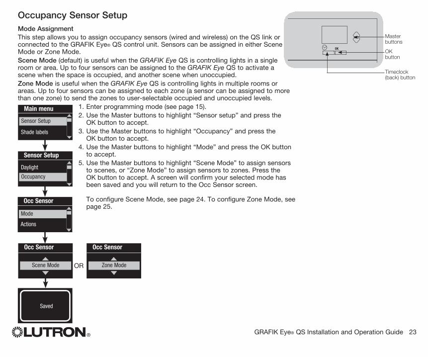
Occupancy Sensor SetupMode Assignment
This step allows you to assign occupancy sensors (wired and wireless) on the QS link or connected to the GRAFIK Eye® QS control unit. Sensors can be assigned in either Scene Mode or Zone Mode.
Scene Mode (default) is useful when the GRAFIK Eye QS is controlling lights in a single room or area. Up to four sensors can be assigned to the GRAFIK Eye QS to activate a scene when the space is occupied, and another scene when unoccupied.
Zone Mode is useful when the GRAFIK Eye QS is controlling lights in multiple rooms or areas. Up to four sensors can be assigned to each zone (a sensor can be assigned to more than one zone) to send the zones to user-selectable occupied and unoccupied levels.
1. Enter programming mode (see page 15).2. Use the Master buttons to highlight “Sensor setup” and press the
OK button to accept. 3. Use the Master buttons to highlight “Occupancy” and press the
OK button to accept.4. Use the Master buttons to highlight “Mode” and press the OK button
to accept.5. Use the Master buttons to highlight “Scene Mode” to assign sensors
to scenes, or “Zone Mode” to assign sensors to zones. Press the OK button to accept. A screen will confirm your selected mode has been saved and you will return to the Occ Sensor screen. To configure Scene Mode, see page 24. To configure Zone Mode, see page 25.
Main menu
Zone Setup
Shade labels
Sensor Setup
Occ Sensor
Scene Mode
Occ Sensor
Actions
Mode
SavedSaved
Occ Sensor
Zone ModeOR
OK
1 2 3 4 5 6
Master buttons
OK button
Timeclock (back) button
Sensor Setup
Daylight
Occupancy
® GRAFIK Eye® QS Installation and Operation Guide 24
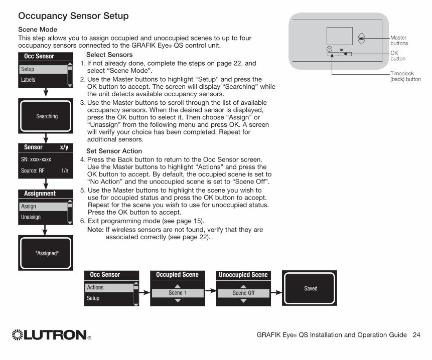
Occupancy Sensor SetupScene Mode
This step allows you to assign occupied and unoccupied scenes to up to four occupancy sensors connected to the GRAFIK Eye® QS control unit.
Select Sensors1. If not already done, complete the steps on page 22, and
select “Scene Mode”.2. Use the Master buttons to highlight “Setup” and press the
OK button to accept. The screen will display “Searching” while the unit detects available occupancy sensors.
3. Use the Master buttons to scroll through the list of available occupancy sensors. When the desired sensor is displayed, press the OK button to select it. Then choose “Assign” or “Unassign” from the following menu and press OK. A screen will verify your choice has been completed. Repeat for additional sensors.
Set Sensor Action4. Press the Back button to return to the Occ Sensor screen.
Use the Master buttons to highlight “Actions” and press the OK button to accept. By default, the occupied scene is set to “No Action” and the unoccupied scene is set to “Scene Off”.
5. Use the Master buttons to highlight the scene you wish to use for occupied status and press the OK button to accept. Repeat for the scene you wish to use for unoccupied status. Press the OK button to accept.
6. Exit programming mode (see page 15). Note: If wireless sensors are not found, verify that they are
associated correctly (see page 22).
SavedSaved
3 seconds
Occ Sensor
Setup
Actions
Occupied Scene
Scene 1
Unoccupied Scene
Scene Off
Occ Sensor
Labels
Setup
Sensor x/y
SN: xxxx-xxxx
Source: RF 1/n
Assignment
Unassign
Assign
Saved*Assigned*
SavedSearching
OK
1 2 3 4 5 6
Master buttons
OK button
Timeclock (back) button
® GRAFIK Eye® QS Installation and Operation Guide 25
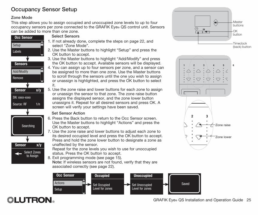
Occupancy Sensor SetupZone Mode
This step allows you to assign occupied and unoccupied zone levels to up to four occupancy sensors per zone connected to the GRAFIK Eye® QS control unit. Sensors can be added to more than one zone.
Select Sensors1. If not already done, complete the steps on page 22, and
select “Zone Mode”.2. Use the Master buttons to highlight “Setup” and press the
OK button to accept.3. Use the Master buttons to highlight “Add/Modify” and press
the OK button to accept. Available sensors will be displayed.4. You can assign up to four sensors per zone, and a sensor can
be assigned to more than one zone. Use the Master buttons to scroll through the sensors until the one you wish to assign or unassign is highlighted, and press the OK button to select it.
5. Use the zone raise and lower buttons for each zone to assign or unassign the sensor to that zone. The zone raise button assigns the displayed sensor, and the zone lower button unassigns it. Repeat for all desired sensors and press OK. A screen will verify your settings have been saved.
Set Sensor Action6. Press the Back button to return to the Occ Sensor screen.
Use the Master buttons to highlight “Actions” and press the OK button to accept.
7. Use the zone raise and lower buttons to adjust each zone to its desired occupied level and press the OK button to accept. Press and hold the zone lower button to designate a zone as unaffected by the sensor. Repeat for the zone levels you wish to use for unoccupied status. Press the OK button to accept.
8. Exit programming mode (see page 15). Note: If wireless sensors are not found, verify that they are
associated correctly (see page 22).
Sensor x/y
Select Zones to Assign
Occupied Set Occupied Level for zones
OK
1 2 3 4 5 6
OK
1 2 3 4 5 6
Zone raise
Zone lower
Occ Sensor
Labels
Setup
Sensors
Remove
Add/Modify
Sensor x/y
SN: xxxx-xxxx
Source: RF 1/n
Unoccupied Set Unoccupied Level for zones
SavedSaved 3 seconds
Occ Sensor
Setup
Actions
SavedSearching
OK
1 2 3 4 5 6
Master buttons
OK button
Timeclock (back) button
® GRAFIK Eye® QS Installation and Operation Guide 26
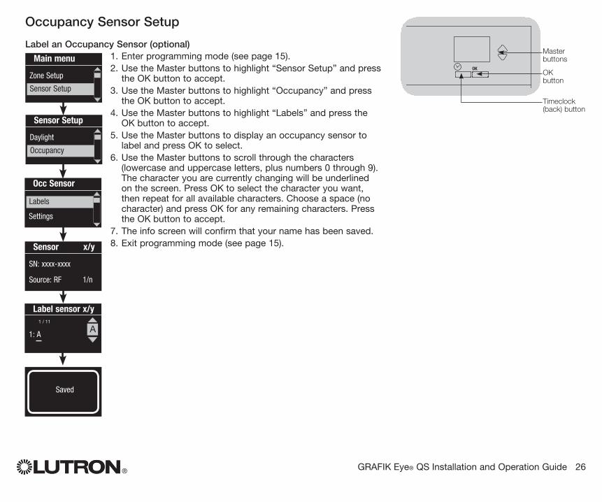
Occupancy Sensor Setup
Label an Occupancy Sensor (optional)1. Enter programming mode (see page 15).2. Use the Master buttons to highlight “Sensor Setup” and press
the OK button to accept.3. Use the Master buttons to highlight “Occupancy” and press
the OK button to accept.4. Use the Master buttons to highlight “Labels” and press the
OK button to accept.5. Use the Master buttons to display an occupancy sensor to
label and press OK to select.6. Use the Master buttons to scroll through the characters
(lowercase and uppercase letters, plus numbers 0 through 9). The character you are currently changing will be underlined on the screen. Press OK to select the character you want, then repeat for all available characters. Choose a space (no character) and press OK for any remaining characters. Press the OK button to accept.
7. The info screen will confirm that your name has been saved.8. Exit programming mode (see page 15).
SavedSaved
Main menu
Zone Setup
Sensor Setup
Occ Sensor
Settings
Labels
Sensor x/y
SN: xxxx-xxxx
Source: RF 1/n
OK
1 2 3 4 5 6
Master buttons
OK button
Timeclock (back) button
Label sensor x/y
1: AA
1 / 11
Sensor Setup
Daylight
Occupancy
® GRAFIK Eye® QS Installation and Operation Guide 27
Occupancy Sensor Setup
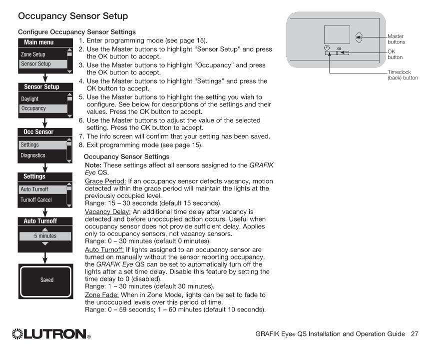
Configure Occupancy Sensor Settings1. Enter programming mode (see page 15).2. Use the Master buttons to highlight “Sensor Setup” and press
the OK button to accept.3. Use the Master buttons to highlight “Occupancy” and press
the OK button to accept.4. Use the Master buttons to highlight “Settings” and press the
OK button to accept.5. Use the Master buttons to highlight the setting you wish to
configure. See below for descriptions of the settings and their values. Press the OK button to accept.
6. Use the Master buttons to adjust the value of the selected setting. Press the OK button to accept.
7. The info screen will confirm that your setting has been saved.8. Exit programming mode (see page 15).
Occupancy Sensor Settings Note: These settings affect all sensors assigned to the GRAFIK
Eye QS. Grace Period: If an occupancy sensor detects vacancy, motion
detected within the grace period will maintain the lights at the previously occupied level. Range: 15 – 30 seconds (default 15 seconds).
Vacancy Delay: An additional time delay after vacancy is detected and before unoccupied action occurs. Useful when occupancy sensor does not provide sufficient delay. Applies only to occupancy sensors, not vacancy sensors. Range: 0 – 30 minutes (default 0 minutes).
Auto Turnoff: If lights assigned to an occupancy sensor are turned on manually without the sensor reporting occupancy, the GRAFIK Eye QS can be set to automatically turn off the lights after a set time delay. Disable this feature by setting the time delay to 0 (disabled). Range: 1 – 30 minutes (default 30 minutes).
Zone Fade: When in Zone Mode, lights can be set to fade to the unoccupied levels over this period of time. Range: 0 – 59 seconds; 1 – 60 minutes (default 10 seconds).
Auto Turnoff
5 minutes
SavedSaved
Main menu
Zone Setup
Sensor Setup
Occ Sensor
Diagnostics
Settings
Settings
Turnoff Cancel
Auto Turnoff
OK
1 2 3 4 5 6
Master buttons
OK button
Timeclock (back) button
Sensor Setup
Daylight
Occupancy
® GRAFIK Eye® QS Installation and Operation Guide 28
OK
1 2 3 4 5 6
Master buttons
OK button
Timeclock (back) button
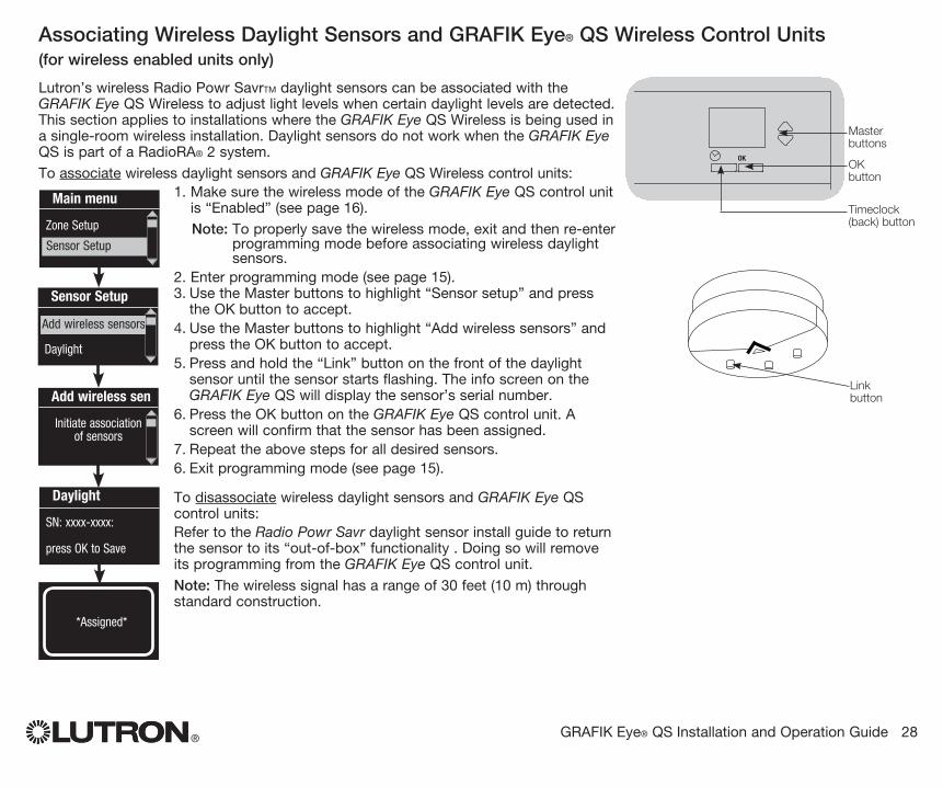
Lutron’s wireless Radio Powr SavrTM daylight sensors can be associated with the GRAFIK Eye QS Wireless to adjust light levels when certain daylight levels are detected.This section applies to installations where the GRAFIK Eye QS Wireless is being used in a single-room wireless installation. Daylight sensors do not work when the GRAFIK Eye QS is part of a RadioRA® 2 system.
To associate wireless daylight sensors and GRAFIK Eye QS Wireless control units:1. Make sure the wireless mode of the GRAFIK Eye QS control unit
is “Enabled” (see page 16). Note: To properly save the wireless mode, exit and then re-enter
programming mode before associating wireless daylight sensors.
2. Enter programming mode (see page 15).3. Use the Master buttons to highlight “Sensor setup” and press
the OK button to accept. 4. Use the Master buttons to highlight “Add wireless sensors” and
press the OK button to accept. 5. Press and hold the “Link” button on the front of the daylight
sensor until the sensor starts flashing. The info screen on the GRAFIK Eye QS will display the sensor’s serial number.
6. Press the OK button on the GRAFIK Eye QS control unit. A screen will confirm that the sensor has been assigned.
7. Repeat the above steps for all desired sensors.6. Exit programming mode (see page 15).
To disassociate wireless daylight sensors and GRAFIK Eye QS control units:Refer to the Radio Powr Savr daylight sensor install guide to return the sensor to its “out-of-box” functionality . Doing so will remove its programming from the GRAFIK Eye QS control unit.
Note: The wireless signal has a range of 30 feet (10 m) through standard construction.
Associating Wireless Daylight Sensors and GRAFIK Eye® QS Wireless Control Units (for wireless enabled units only)
Main menu
Zone Setup
Sensor Setup
Daylight
SN: xxxx-xxxx:
press OK to Save
Add wireless sen
Initiate association of sensors
Saved*Assigned*
Sensor Setup
Daylight
Add wireless sensors
Link button
® GRAFIK Eye® QS Installation and Operation Guide 29
OK
1 2 3 4 5 6
Master buttons
OK button
Timeclock (back) button
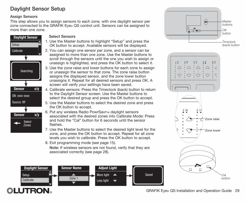
Daylight Sensor SetupAssign Sensors
This step allows you to assign sensors to each zone, with one daylight sensor per zone connected to the GRAFIK Eye® QS control unit. Sensors can be assigned to more than one zone.
Select Sensors1. Use the Master buttons to highlight “Setup” and press the
OK button to accept. Available sensors will be displayed.2. You can assign one sensor per zone, and a sensor can be
assigned to more than one zone. Use the Master buttons to scroll through the sensors until the one you wish to assign or unassign is highlighted, and press the OK button to select it.
3. Use the zone raise and lower buttons for each zone to assign or unassign the sensor to that zone. The zone raise button assigns the displayed sensor, and the zone lower button unassigns it. Repeat for all desired sensors and press OK. A screen will verify your settings have been saved.
4. Calibrate sensors: Press the Timeclock (back) button to return to the Daylight Sensor screen. Use the Master buttons to select the desired group and press the OK button to accept.
5. Use the Master buttons to select the desired zone and press the OK button to accept.
6. Put any wireless Radio PowrSavrTM daylight sensors associated with the desired zones into Calibrate Mode: Press and hold the “Cal” button for 6 seconds until the sensor flashes.
7. Use the Master buttons to select the desired light level for the zone, and press the OK button to accept. Repeat for all zone levels you wish to calibrate. Press the OK button to accept.
8. Exit programming mode (see page 15). Note: If wireless sensors are not found, verify that they are
associated correctly (see page 28).
Sensor x/y
Select Zones
OK
1 2 3 4 5 69 10 11 12 13 14 7 815 16
9-161-8
OK
1 2 3 4 5 69 10 11 12 13 14 7 815 16
9-161-8
Zone raise
Zone lower
Daylight Sensor
Calibrate
Setup
Sensor x/y
SN: xxxx-xxxx:
Source: RF
SavedSaved
3 seconds
Daylight Sensor
Setup
Calibrate
SavedSearching
Sensor Name
Zone 1
Adjust Light
More light
Less light
Cal button
® GRAFIK Eye® QS Installation and Operation Guide 30
OK
1 2 3 4 5 6
Master buttons
OK button
Timeclock (back) button
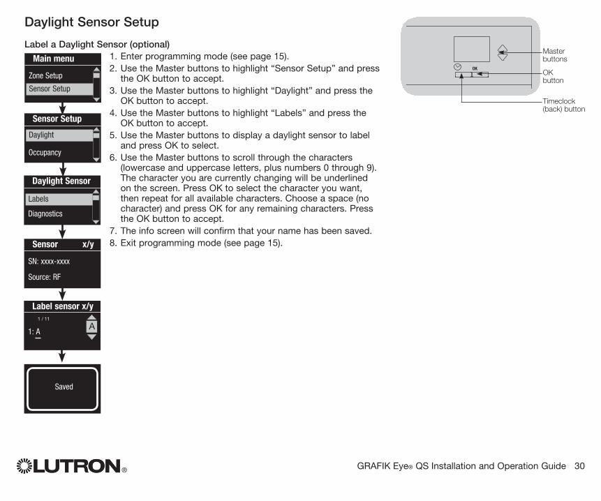
Daylight Sensor Setup
Label a Daylight Sensor (optional)1. Enter programming mode (see page 15).2. Use the Master buttons to highlight “Sensor Setup” and press
the OK button to accept.3. Use the Master buttons to highlight “Daylight” and press the
OK button to accept.4. Use the Master buttons to highlight “Labels” and press the
OK button to accept.5. Use the Master buttons to display a daylight sensor to label
and press OK to select.6. Use the Master buttons to scroll through the characters
(lowercase and uppercase letters, plus numbers 0 through 9). The character you are currently changing will be underlined on the screen. Press OK to select the character you want, then repeat for all available characters. Choose a space (no character) and press OK for any remaining characters. Press the OK button to accept.
7. The info screen will confirm that your name has been saved.8. Exit programming mode (see page 15).
SavedSaved
Main menu
Zone Setup
Sensor Setup
Daylight Sensor
Diagnostics
Labels
Sensor x/y
SN: xxxx-xxxx
Source: RF
Label sensor x/y
1: AA
1 / 11
Sensor Setup
Occupancy
Daylight
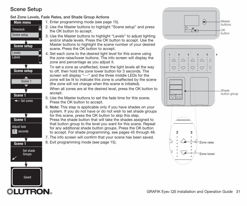
Scene SetupSet Zone Levels, Fade Rates, and Shade Group Actions
1. Enter programming mode (see page 15).2. Use the Master buttons to highlight “Scene setup” and press
the OK button to accept.3. Use the Master buttons to highlight “Levels” to adjust lighting
and/or shade levels. Press the OK button to accept. Use the Master buttons to highlight the scene number of your desired scene. Press the OK button to accept.
4. Set each zone to the desired light level for this scene using the zone raise/lower buttons. The info screen will display the zone and percentage as you adjust it.
To set a zone as unaffected, lower the light levels all the way to off, then hold the zone lower button for 3 seconds. The screen will display “---” and the three middle LEDs for the zone will be lit to indicate this zone is unaffected by the scene (the zone will not change when this scene is initiated).
When all zones are at the desired level, press the OK button to accept.
5. Use the Master buttons to set the fade time for this scene. Press the OK button to accept.
6. Note: This step is applicable only if you have shades on your system. If you do not have or do not wish to set shade groups for this scene, press the OK button to skip this step. Press the shade button that will take the shades assigned to that button group to the level you want for this scene. Repeat for any additional shade button groups. Press the OK button to accept. For shade programming, see pages 45 through 48.
7. The info screen will confirm that your scene has been saved.8. Exit programming mode (see page 15).
® GRAFIK Eye® QS Installation and Operation Guide 31
OK
1 2 3 4 5 6
Master buttons
OK button
Main menu
Timeclock
Scene setup
Scene setup
LabelsLevels
Scene 1
Adjust fade seconds
Scene 1
Set shade Groups
3 seconds
Scene 1 Set zones
Scene setup
Scene 1
OK
1 2 3 4 5 6
OK
1 2 3 4 5 6
Zone raise
Zone lower
Saved
3
Shade button group
® GRAFIK Eye® QS Installation and Operation Guide 32
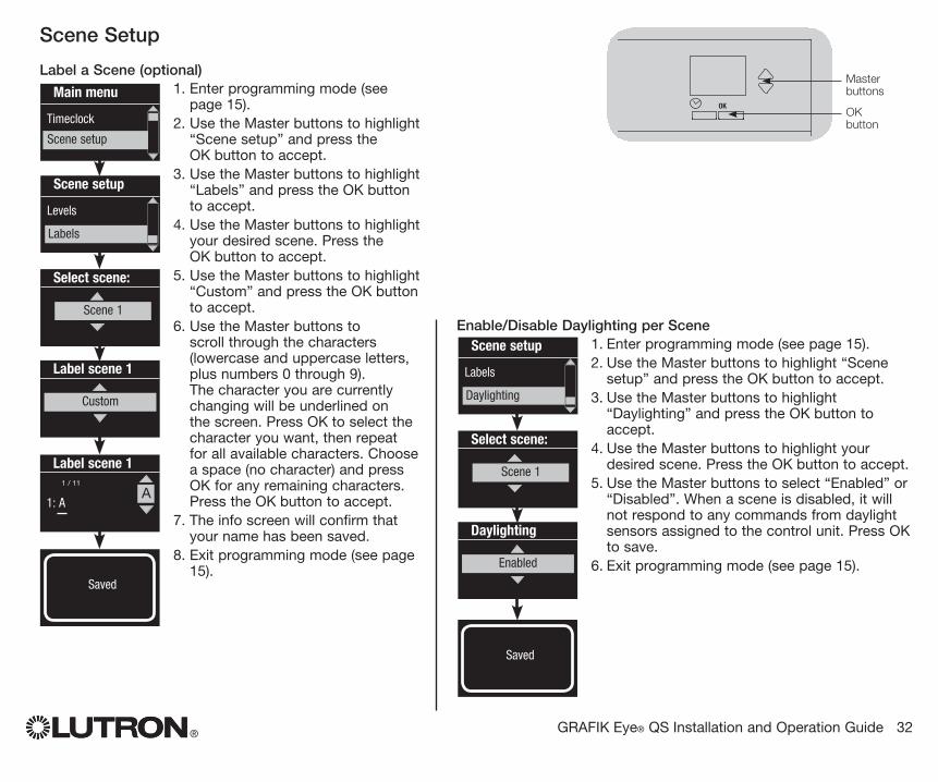
Scene Setup
Label a Scene (optional)1. Enter programming mode (see
page 15).2. Use the Master buttons to highlight
“Scene setup” and press the OK button to accept.
3. Use the Master buttons to highlight “Labels” and press the OK button to accept.
4. Use the Master buttons to highlight your desired scene. Press the OK button to accept.
5. Use the Master buttons to highlight “Custom” and press the OK button to accept.
6. Use the Master buttons to scroll through the characters (lowercase and uppercase letters, plus numbers 0 through 9). The character you are currently changing will be underlined on the screen. Press OK to select the character you want, then repeat for all available characters. Choose a space (no character) and press OK for any remaining characters. Press the OK button to accept.
7. The info screen will confirm that your name has been saved.
8. Exit programming mode (see page 15).
Main menu
Timeclock
Scene setup
Labels
Select scene:
Scene 1
Label scene 1
Custom
Label scene 1
1: AA
1 / 11
OK
1 2 3 4 5 6
Master buttons
OK button
Scene setup
Levels
Labels
Saved
Enable/Disable Daylighting per Scene1. Enter programming mode (see page 15).2. Use the Master buttons to highlight “Scene
setup” and press the OK button to accept.3. Use the Master buttons to highlight
“Daylighting” and press the OK button to accept.
4. Use the Master buttons to highlight your desired scene. Press the OK button to accept.
5. Use the Master buttons to select “Enabled” or “Disabled”. When a scene is disabled, it will not respond to any commands from daylight sensors assigned to the control unit. Press OK to save.
6. Exit programming mode (see page 15).
Labels
Select scene:
Scene 1
Daylighting
Enabled
Scene setup
Labels
Daylighting
Saved
® GRAFIK Eye® QS Installation and Operation Guide 33
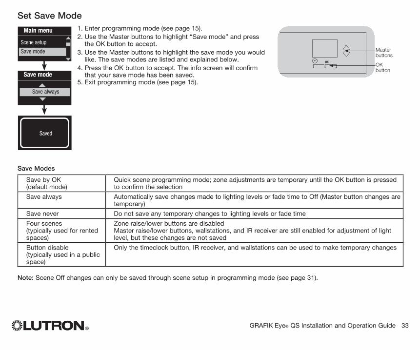
Set Save Mode1. Enter programming mode (see page 15).2. Use the Master buttons to highlight “Save mode” and press
the OK button to accept.3. Use the Master buttons to highlight the save mode you would
like. The save modes are listed and explained below.4. Press the OK button to accept. The info screen will confirm
that your save mode has been saved.5. Exit programming mode (see page 15).
Main menu
Scene setup
Save mode
Save mode
Save always
Save Modes
Save by OK (default mode)
Quick scene programming mode; zone adjustments are temporary until the OK button is pressed to confirm the selection
Save always Automatically save changes made to lighting levels or fade time to Off (Master button changes are temporary)
Save never Do not save any temporary changes to lighting levels or fade time
Four scenes (typically used for rented spaces)
Zone raise/lower buttons are disabled Master raise/lower buttons, wallstations, and IR receiver are still enabled for adjustment of light level, but these changes are not saved
Button disable (typically used in a public space)
Only the timeclock button, IR receiver, and wallstations can be used to make temporary changes
Note: Scene Off changes can only be saved through scene setup in programming mode (see page 31).
OK
1 2 3 4 5 6
Master buttons
OK button
Saved
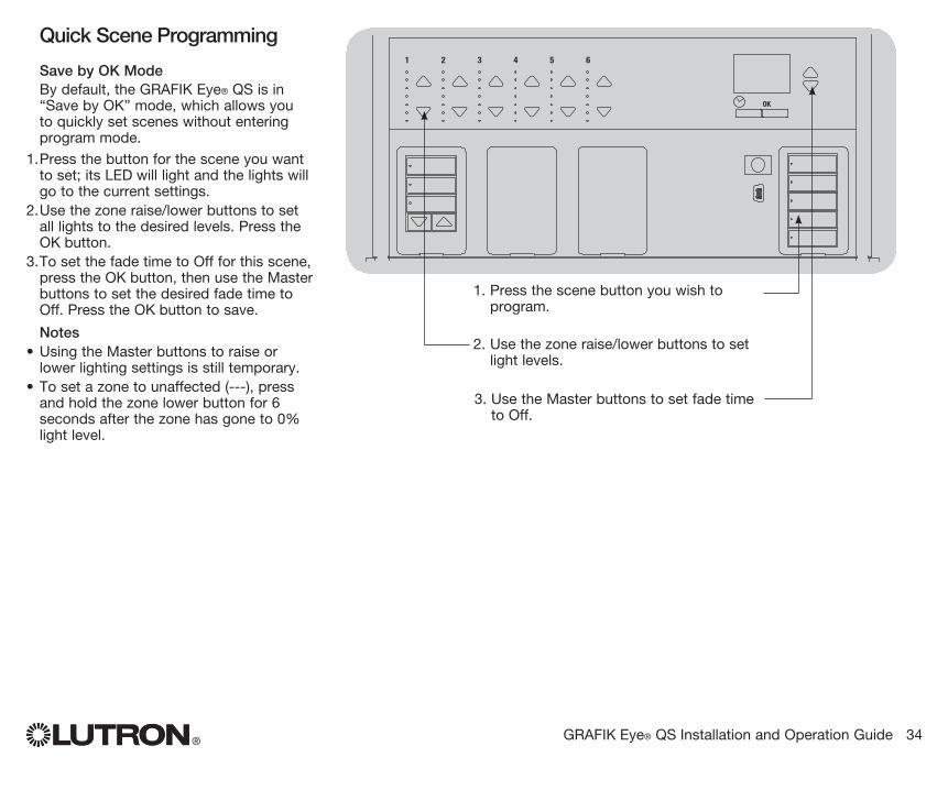
Quick Scene Programming
Save by OK ModeBy default, the GRAFIK Eye® QS is in “Save by OK” mode, which allows you to quickly set scenes without entering program mode.
1. Press the button for the scene you want to set; its LED will light and the lights will go to the current settings.
2. Use the zone raise/lower buttons to set all lights to the desired levels. Press the OK button.
3. To set the fade time to Off for this scene, press the OK button, then use the Master buttons to set the desired fade time to Off. Press the OK button to save.
Notes• Using the Master buttons to raise or
lower lighting settings is still temporary.• To set a zone to unaffected (---), press
and hold the zone lower button for 6 seconds after the zone has gone to 0% light level.
® GRAFIK Eye® QS Installation and Operation Guide 34
OK
1 2 3 4 5 6
1. Press the scene button you wish to program.
2. Use the zone raise/lower buttons to set light levels.
3. Use the Master buttons to set fade time to Off.
® GRAFIK Eye® QS Installation and Operation Guide 35
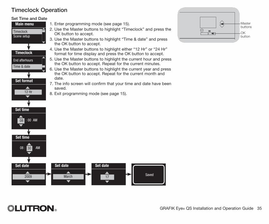
Timeclock OperationSet Time and Date
1. Enter programming mode (see page 15).2. Use the Master buttons to highlight “Timeclock” and press the
OK button to accept.3. Use the Master buttons to highlight “Time & date” and press
the OK button to accept.4. Use the Master buttons to highlight either “12 Hr” or “24 Hr”
format for time display and press the OK button to accept.5. Use the Master buttons to highlight the current hour and press
the OK button to accept. Repeat for the current minutes.6. Use the Master buttons to highlight the current year and press
the OK button to accept. Repeat for the current month and date.
7. The info screen will confirm that your time and date have been saved.
8. Exit programming mode (see page 15).
OK
1 2 3 4 5 6
Master buttons
OK button
Main menu
TimeclockScene setup
Timeclock
End afterhours
Time & date
Set time
: 00 AM 08
Timeclock
Set date
Del: 002009
Set date
Set format
Del: 0012 Hr
March
Set date
17
Set time
08 : AM 30
Saved
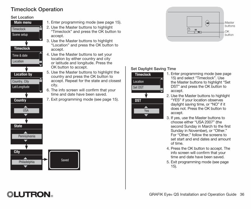
Set Daylight Saving Time1. Enter programming mode (see page
15) and select “Timeclock”. Use the Master buttons to highlight “Set DST” and press the OK button to accept.
2. Use the Master buttons to highlight “YES” if your location observes daylight saving time, or “NO” if it does not. Press the OK button to accept.
3. If yes, use the Master buttons to choose either “USA 2007” (the second Sunday in March to the first Sunday in November), or “Other.” For “Other,” follow the screens to set start and end dates and amount of time.
4. Press the OK button to accept. The info screen will confirm that your time and date have been saved.
5. Exit programming mode (see page 15).
® GRAFIK Eye® QS Installation and Operation Guide 36
Timeclock OperationSet Location
1. Enter programming mode (see page 15).2. Use the Master buttons to highlight
“Timeclock” and press the OK button to accept.
3. Use the Master buttons to highlight “Location” and press the OK button to accept.
4. Use the Master buttons to set your location by either country and city or latitude and longitude. Press the OK button to accept.
5. Use the Master buttons to highlight the country and press the OK button to accept. Repeat for the state and closest city.
6. The info screen will confirm that your time and date have been saved.
7. Exit programming mode (see page 15).
OK
1 2 3 4 5 6
Master buttons
OK button
Main menu
Timeclock
Scene setup
Timeclock
Time & date
Location
Location by
Lat/Longitude
Country, City
Timeclock
State
Pennsylvania
City
Philadelphia
Country
08 : 00USA
Timeclock
Location
Set DST
DST
Del: 00Yes
Saved
® GRAFIK Eye® QS Installation and Operation Guide 37
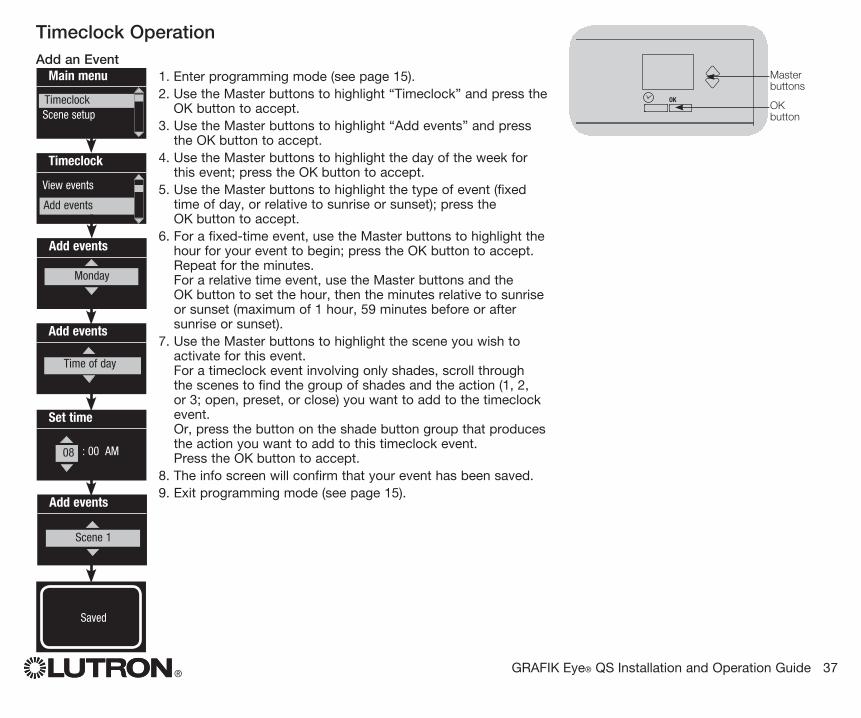
Timeclock OperationAdd an Event
1. Enter programming mode (see page 15).2. Use the Master buttons to highlight “Timeclock” and press the
OK button to accept.3. Use the Master buttons to highlight “Add events” and press
the OK button to accept.4. Use the Master buttons to highlight the day of the week for
this event; press the OK button to accept.5. Use the Master buttons to highlight the type of event (fixed
time of day, or relative to sunrise or sunset); press the OK button to accept.
6. For a fixed-time event, use the Master buttons to highlight the hour for your event to begin; press the OK button to accept. Repeat for the minutes. For a relative time event, use the Master buttons and the OK button to set the hour, then the minutes relative to sunrise or sunset (maximum of 1 hour, 59 minutes before or after sunrise or sunset).
7. Use the Master buttons to highlight the scene you wish to activate for this event. For a timeclock event involving only shades, scroll through the scenes to find the group of shades and the action (1, 2, or 3; open, preset, or close) you want to add to the timeclock event. Or, press the button on the shade button group that produces the action you want to add to this timeclock event. Press the OK button to accept.
8. The info screen will confirm that your event has been saved.9. Exit programming mode (see page 15).
OK
1 2 3 4 5 6
Master buttons
OK button
Main menu
TimeclockScene setup
Timeclock
View events
Add events
Timeclock
Add events
Time of day
Add events
Monday
Add events
Scene Scene 1
Set time
: 00 AM 08
Saved
® GRAFIK Eye® QS Installation and Operation Guide 38
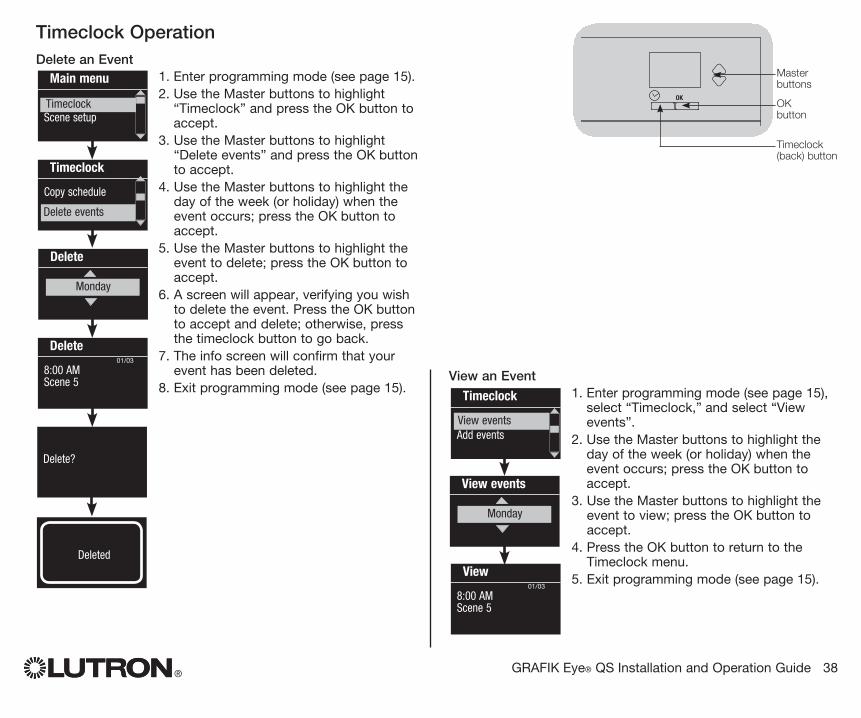
Timeclock OperationDelete an Event
1. Enter programming mode (see page 15).2. Use the Master buttons to highlight
“Timeclock” and press the OK button to accept.
3. Use the Master buttons to highlight “Delete events” and press the OK button to accept.
4. Use the Master buttons to highlight the day of the week (or holiday) when the event occurs; press the OK button to accept.
5. Use the Master buttons to highlight the event to delete; press the OK button to accept.
6. A screen will appear, verifying you wish to delete the event. Press the OK button to accept and delete; otherwise, press the timeclock button to go back.
7. The info screen will confirm that your event has been deleted.
8. Exit programming mode (see page 15).
Main menu
TimeclockScene setup
Timeclock
Copy schedule
Timeclock
Delete?
Delete
8:00 AM Scene 5
Delete
Monday
01/03
View an Event1. Enter programming mode (see page 15),
select “Timeclock,” and select “View events”.
2. Use the Master buttons to highlight the day of the week (or holiday) when the event occurs; press the OK button to accept.
3. Use the Master buttons to highlight the event to view; press the OK button to accept.
4. Press the OK button to return to the Timeclock menu.
5. Exit programming mode (see page 15).
Timeclock
Delete eventsAdd events View events
Monday
View
8:00 AM Scene 5
View events
Monday
01/03
Delete events
Deleted
OK
1 2 3 4 5 6
Master buttons
OK button
Timeclock (back) button
® GRAFIK Eye® QS Installation and Operation Guide 39
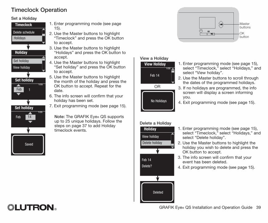
Timeclock OperationSet a Holiday
1. Enter programming mode (see page 15).
2. Use the Master buttons to highlight “Timeclock” and press the OK button to accept.
3. Use the Master buttons to highlight “Holidays” and press the OK button to accept.
4. Use the Master buttons to highlight “Set holiday” and press the OK button to accept.
5. Use the Master buttons to highlight the month of the holiday and press the OK button to accept. Repeat for the date.
6. The info screen will confirm that your holiday has been set.
7. Exit programming mode (see page 15).
Note: The GRAFIK Eye® QS supports up to 25 unique holidays. Follow the steps on page 37 to add Holiday timeclock events.
OK
1 2 3 4 5 6
Master buttons
OK button
Timeclock
Delete schedule
Holiday
Add event
View holiday
Set holiday
Holidays
Set holiday 1/25
1 Feb
Monday
Set holiday 1/25
Feb 14
Delete a Holiday1. Enter programming mode (see page 15),
select “Timeclock,” select “Holidays,” and select “Delete holiday”.
2. Use the Master buttons to highlight the holiday you wish to delete and press the OK button to accept.
3. The info screen will confirm that your event has been deleted.
4. Exit programming mode (see page 15).
Holiday
View holiday
Delete holiday
Monday
Feb 14
Delete?
Saved
Deleted
View a Holiday1. Enter programming mode (see page 15),
select “Timeclock,” select “Holidays,” and select “View holiday”.
2. Use the Master buttons to scroll through the dates of the programmed holidays.
3. If no holidays are programmed, the info screen will display a screen informing you.
4. Exit programming mode (see page 15).
View Holiday 1/25
Feb 14
MondayNo Holidays
OR
® GRAFIK Eye® QS Installation and Operation Guide 40
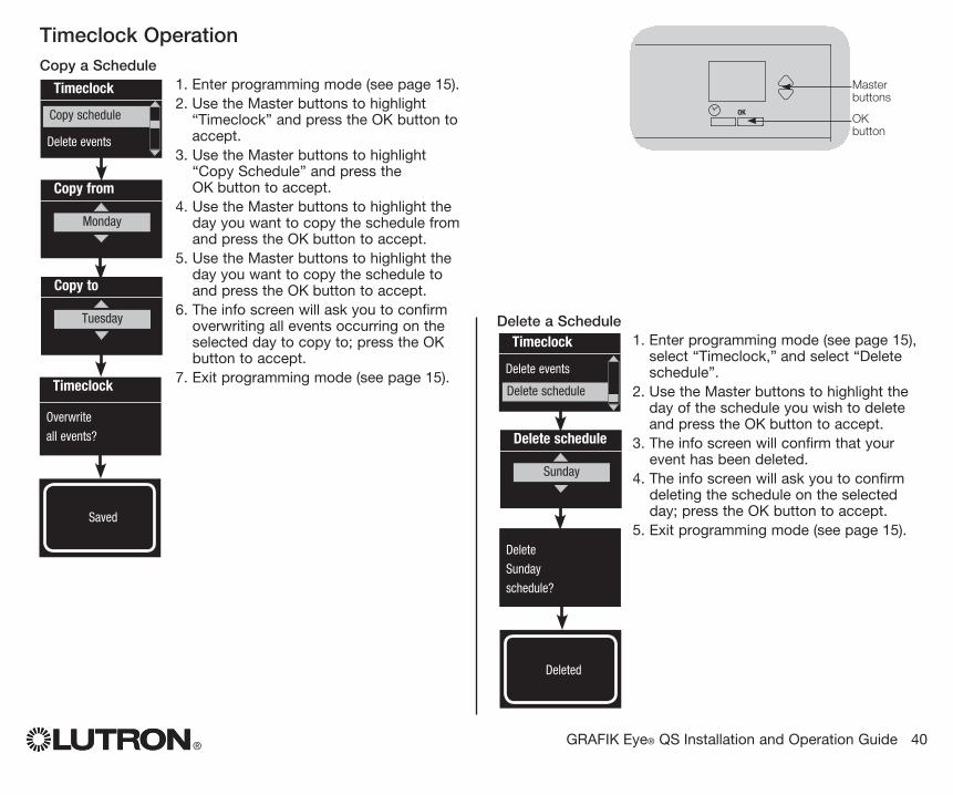
Timeclock OperationCopy a Schedule
1. Enter programming mode (see page 15).2. Use the Master buttons to highlight
“Timeclock” and press the OK button to accept.
3. Use the Master buttons to highlight “Copy Schedule” and press the OK button to accept.
4. Use the Master buttons to highlight the day you want to copy the schedule from and press the OK button to accept.
5. Use the Master buttons to highlight the day you want to copy the schedule to and press the OK button to accept.
6. The info screen will ask you to confirm overwriting all events occurring on the selected day to copy to; press the OK button to accept.
7. Exit programming mode (see page 15).
OK
1 2 3 4 5 6
Master buttons
OK button
Timeclock
Delete schedule
Delete events
Copy schedule
Copy from
Monday
Monday
Timeclock
Overwrite
all events?
Delete a Schedule1. Enter programming mode (see page 15),
select “Timeclock,” and select “Delete schedule”.
2. Use the Master buttons to highlight the day of the schedule you wish to delete and press the OK button to accept.
3. The info screen will confirm that your event has been deleted.
4. The info screen will ask you to confirm deleting the schedule on the selected day; press the OK button to accept.
5. Exit programming mode (see page 15).
Timeclock
Delete events
Delete schedule
Saved
Monday
Delete
Sunday
schedule?
Deleted
Monday
Copy to
Tuesday
Monday
Delete schedule
Sunday
® GRAFIK Eye® QS Installation and Operation Guide 41
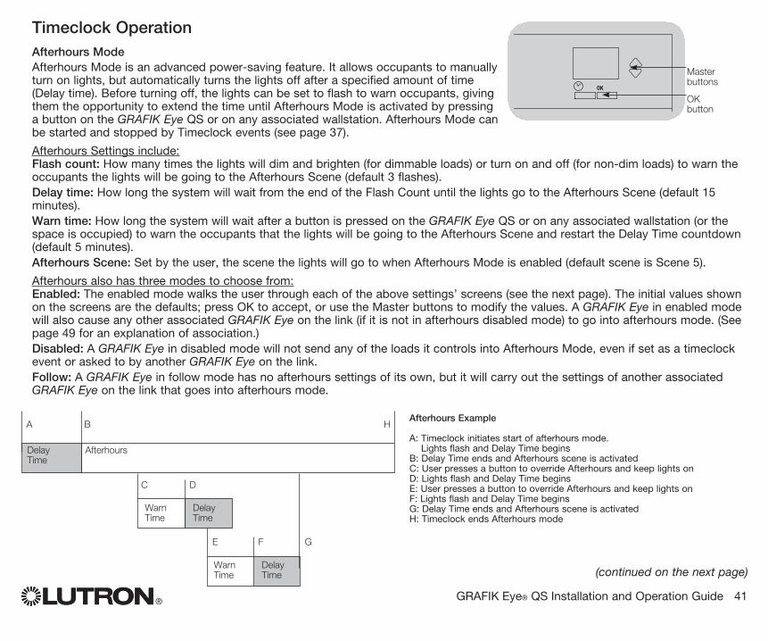
Timeclock OperationAfterhours ModeAfterhours Mode is an advanced power-saving feature. It allows occupants to manually turn on lights, but automatically turns the lights off after a specified amount of time (Delay time). Before turning off, the lights can be set to flash to warn occupants, giving them the opportunity to extend the time until Afterhours Mode is activated by pressing a button on the GRAFIK Eye QS or on any associated wallstation. Afterhours Mode can be started and stopped by Timeclock events (see page 37).
Afterhours Settings include:Flash count: How many times the lights will dim and brighten (for dimmable loads) or turn on and off (for non-dim loads) to warn the occupants the lights will be going to the Afterhours Scene (default 3 flashes).Delay time: How long the system will wait from the end of the Flash Count until the lights go to the Afterhours Scene (default 15 minutes).Warn time: How long the system will wait after a button is pressed on the GRAFIK Eye QS or on any associated wallstation (or the space is occupied) to warn the occupants that the lights will be going to the Afterhours Scene and restart the Delay Time countdown (default 5 minutes). Afterhours Scene: Set by the user, the scene the lights will go to when Afterhours Mode is enabled (default scene is Scene 5).
Afterhours also has three modes to choose from:Enabled: The enabled mode walks the user through each of the above settings’ screens (see the next page). The initial values shown on the screens are the defaults; press OK to accept, or use the Master buttons to modify the values. A GRAFIK Eye in enabled mode will also cause any other associated GRAFIK Eye on the link (if it is not in afterhours disabled mode) to go into afterhours mode. (See page 49 for an explanation of association.)Disabled: A GRAFIK Eye in disabled mode will not send any of the loads it controls into Afterhours Mode, even if set as a timeclock event or asked to by another GRAFIK Eye on the link.Follow: A GRAFIK Eye in follow mode has no afterhours settings of its own, but it will carry out the settings of another associated GRAFIK Eye on the link that goes into afterhours mode.
(continued on the next page)
OK
1 2 3 4 5 6
Master buttons
OK button
A B
C D
E F G
Delay Time
Afterhours
Delay Time
Delay Time
Warn Time
Warn Time
Afterhours Example
A: Timeclock initiates start of afterhours mode. Lights flash and Delay Time begins
B: Delay Time ends and Afterhours scene is activatedC: User presses a button to override Afterhours and keep lights onD: Lights flash and Delay Time beginsE: User presses a button to override Afterhours and keep lights onF: Lights flash and Delay Time beginsG: Delay Time ends and Afterhours scene is activatedH: Timeclock ends Afterhours mode
H
® GRAFIK Eye® QS Installation and Operation Guide 42
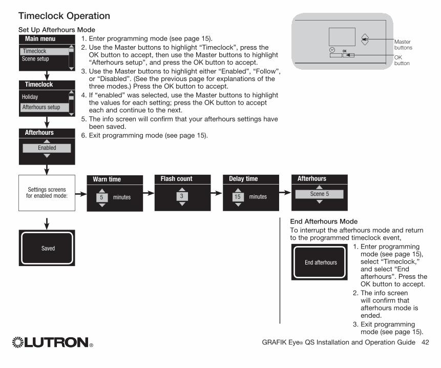
Timeclock OperationSet Up Afterhours Mode
1. Enter programming mode (see page 15).2. Use the Master buttons to highlight “Timeclock”, press the
OK button to accept, then use the Master buttons to highlight “Afterhours setup”, and press the OK button to accept.
3. Use the Master buttons to highlight either “Enabled”, “Follow”, or “Disabled”. (See the previous page for explanations of the three modes.) Press the OK button to accept.
4. If “enabled” was selected, use the Master buttons to highlight the values for each setting; press the OK button to accept each and continue to the next.
5. The info screen will confirm that your afterhours settings have been saved.
6. Exit programming mode (see page 15).
OK
1 2 3 4 5 6
Master buttons
OK button
Afterhours
Enabled
Flash count
3
Saved
Warn time
minutes 5
Delay time
minutes15
Afterhours
Scene 5
End Afterhours Mode To interrupt the afterhours mode and return
to the programmed timeclock event, 1. Enter programming
mode (see page 15), select “Timeclock,” and select “End afterhours”. Press the OK button to accept.
2. The info screen will confirm that afterhours mode is ended.
3. Exit programming mode (see page 15).
End afterhours
Main menu
TimeclockScene setup
Timeclock
Holiday
Afterhours setup
Timeclock
Settings screens for enabled mode:

® GRAFIK Eye® QS Installation and Operation Guide 43
When a GRAFIK Eye QS wireless system includes a Pico wireless control, you can use the Pico wireless control as either a scene controller or a zone controller. This page describes using the Pico wireless control as a scene controller; the next page describes using it as a zone controller.
To use the Pico wireless control as a scene controller with a GRAFIK Eye QS Wireless control unit:1. Make sure the wireless mode of the GRAFIK Eye QS control unit is “Enabled” (see page 16).2. On the Pico, press and hold the top (on) and bottom (off) buttons for 3 seconds. The LED on the Pico
will flash slowly, and the scene button LEDs on the GRAFIK Eye QS will all flash.3. On the GRAFIK Eye QS, the info screen will ask for confirmation that you wish to change the type;
press the OK button. Use the Master buttons on the GRAFIK Eye QS to select “Scene”. Press OK to save.
4. To associate the GRAFIK Eye QS with the Pico, press and hold the top scene button on the GRAFIK Eye QS for 3 seconds (until the LEDs all flash).To disassociate the GRAFIK Eye QS with the Pico, press and hold the bottom scene button on the GRAFIK Eye QS for 3 seconds (until the LEDs stop flashing).
5. On the Pico, press and hold the top (on) and bottom (off) buttons for 3 seconds. The LED on the Pico and the LEDs on associated GRAFIK Eye QS Wireless control units will stop flashing.
Functionality of the Pico control when programmed as a scene controller:
Top button: Scene 1
Center round button: Scene 16
Bottom button: Off
Note: The wireless signal has a range of 30 feet (10 m) through standard construction.
Light
On
Adjust
Off
Change type?
Scene SavedSaved
Pico
Change type?
Press OK
OK
1 2 3 4 5 6
On the GRAFIK Eye QS control unit, press and hold the top scene button for 3 seconds to associate, or press and hold the bottom scene button for 3 seconds to disassociate with the Pico control.
Associate
OR
Disassociate
Associating Pico® Wireless Controls and GRAFIK Eye® QS Wireless Control Units
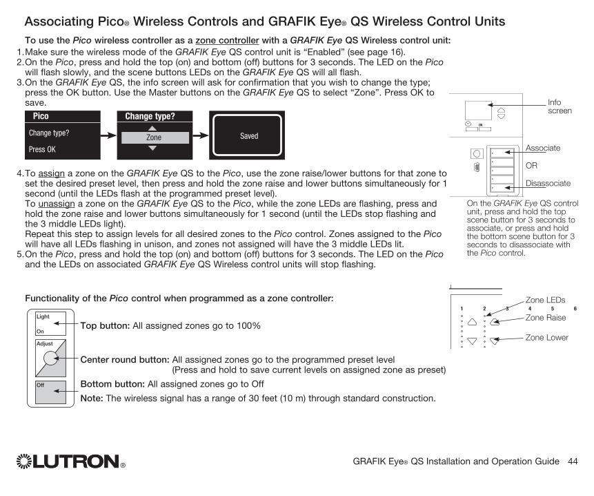
® GRAFIK Eye® QS Installation and Operation Guide 44
To use the Pico wireless controller as a zone controller with a GRAFIK Eye QS Wireless control unit:1. Make sure the wireless mode of the GRAFIK Eye QS control unit is “Enabled” (see page 16).2. On the Pico, press and hold the top (on) and bottom (off) buttons for 3 seconds. The LED on the Pico
will flash slowly, and the scene buttons LEDs on the GRAFIK Eye QS will all flash.3. On the GRAFIK Eye QS, the info screen will ask for confirmation that you wish to change the type;
press the OK button. Use the Master buttons on the GRAFIK Eye QS to select “Zone”. Press OK to save.
4. To assign a zone on the GRAFIK Eye QS to the Pico, use the zone raise/lower buttons for that zone to set the desired preset level, then press and hold the zone raise and lower buttons simultaneously for 1 second (until the LEDs flash at the programmed preset level). To unassign a zone on the GRAFIK Eye QS to the Pico, while the zone LEDs are flashing, press and hold the zone raise and lower buttons simultaneously for 1 second (until the LEDs stop flashing and the 3 middle LEDs light). Repeat this step to assign levels for all desired zones to the Pico control. Zones assigned to the Pico will have all LEDs flashing in unison, and zones not assigned will have the 3 middle LEDs lit.
5. On the Pico, press and hold the top (on) and bottom (off) buttons for 3 seconds. The LED on the Pico and the LEDs on associated GRAFIK Eye QS Wireless control units will stop flashing.
Functionality of the Pico control when programmed as a zone controller:
Top button: All assigned zones go to 100%
Center round button: All assigned zones go to the programmed preset level(Press and hold to save current levels on assigned zone as preset)
Bottom button: All assigned zones go to Off
Note: The wireless signal has a range of 30 feet (10 m) through standard construction.
Light
On
Adjust
Off
Change type?
Zone SavedSaved
Pico
Change type?
Press OK
OK
1 2 3 4 5 6
On the GRAFIK Eye QS control unit, press and hold the top scene button for 3 seconds to associate, or press and hold the bottom scene button for 3 seconds to disassociate with the Pico control.
Associate
OR
Disassociate
Info screen
Associating Pico® Wireless Controls and GRAFIK Eye® QS Wireless Control Units
OK
1 2 3 4 5 6Zone LEDs
Zone Raise
Zone Lower

® GRAFIK Eye® QS Installation and Operation Guide 45
For Sivoia QS Shades wired directly to the GRAFIK Eye QS control unit:
To associate or disassociate shades with a shade button group:
1. On the GRAFIK Eye QS shade button group you wish to assign shades to, enter shade programming mode: Press and hold the top (open) and bottom (close) buttons simultaneously for 3 seconds. The top and bottom LEDs will flash. Shades that are unassigned will move to up (open), and shades that are assigned will move to close (down).
2. Tap the top (open) button to start assigning.
3. Tap the top (open) button repeatedly to cycle forward through the addresses; tap the bottom (close) button to cycle backward.
4. Press the shade group lower button to associate the shade. Press the shade group raise button to disassociate the shade.
5. Exit shade programming mode: Press and hold the top (open) and bottom (close) buttons simultaneously for 3 seconds. The top and bottom LEDs will stop flashing.
When a GRAFIK Eye QS system consists of Sivoia QS shades (or drapes) and a GRAFIK Eye QS with one or more shade button groups, you can associate the shade button groups on the control unit with the shades so the shade buttons can directly control the shades.
Associating Sivoia® QS Shades/Drapes and GRAFIK Eye® QS Control Units
Press and hold the top (open) and bottom (close) buttons on the GRAFIK Eye QS shade button group to enter or exit shade programming mode.
OK
1 2 3 4 5 6
Open
Preset
Close
Sivoia QS Wireless shade/drape EDU
LED
For Wireless Sivoia QS Shades:
To associate shades with a shade button group:1. Make sure the wireless mode of the GRAFIK Eye QS control
unit is “Enabled” (see page 16).2. On the GRAFIK Eye QS shade button group you wish
to assign shades to, enter shade programming mode: Press and hold the top (open) and bottom (close) buttons simultaneously for 3 seconds. The top and bottom LEDs will flash.
3. The LEDs on the electronic drive unit (EDU) and the wireless antenna of unassociated shades/drapes will blink slowly. On the shade/drape that you wish to associate with the shade button group, tap any button; the LED on the EDU will blink rapidly to indicate the shade is now associated with the shade button group on the GRAFIK Eye QS.
4. Repeat step 2 to associate additional shades/drapes to that shade button group.
5. Exit shade programming mode: Press and hold the top (open) and bottom (close) buttons simultaneously for 3 seconds. The top and bottom LEDs will stop flashing.
6. Repeat steps 1 through 5 for additional shade button groups, as applicable.
To disassociate shades with a shade button group: Repeat, in the same order, the steps above for associating
shades/drapes. When in shade programming mode, tap any button on the electronic drive unit (EDU) of the shades/drapes that you wish to disassociate from the shade button group; the green LEDs on the EDU and antenna will blink slowly to indicate the shade is disassociated from the shade button group on the GRAFIK Eye QS.
Note: The wireless signal has a range of 30 feet (10 m) through standard construction.
Lower button: Press to associateRaise button: Press to disassociate
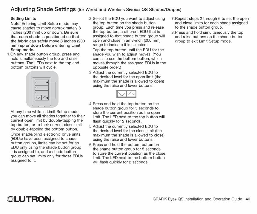
Setting LimitsNote: Entering Limit Setup mode may cause shades to move approximately 8 inches (200 mm) up or down. Be sure that each shade is positioned so that the fabric can safely move 8 inches (200 mm) up or down before entering Limit Setup mode .
1. On any shade button group, press and hold simultaneously the top and raise buttons. The LEDs next to the top and bottom buttons will cycle.
At any time while in Limit Setup mode, you can move all shades together to their current open limit by double-tapping the top button, or to their current close limit by double-tapping the bottom button.
Once shade/blind electronic drive units (EDUs) have been assigned to shade button groups, limits can be set for an EDU only using the shade button group it is assigned to, and a shade button group can set limits only for those EDUs assigned to it.
2. Select the EDU you want to adjust using the top button on the shade button group. Each time you press and release the top button, a different EDU that is assigned to that shade button group will open and close in an 8-inch (200 mm) range to indicate it is selected.
Tap the top button until the EDU for the shade you wish to adjust moves. (You can also use the bottom button, which moves through the assigned EDUs in the opposite order.)
3. Adjust the currently selected EDU to the desired level for the open limit (the maximum the shade is allowed to open) using the raise and lower buttons.
4. Press and hold the top button on the shade button group for 5 seconds to store the current position as the open limit. The LED next to the top button will flash quickly for 2 seconds.
5. Adjust the currently selected EDU to the desired level for the close limit (the maximum the shade is allowed to close) using the raise and lower buttons.
6. Press and hold the bottom button on the shade button group for 5 seconds to store the current position as the close limit. The LED next to the bottom button will flash quickly for 2 seconds.
7. Repeat steps 2 through 6 to set the open and close limits for each shade assigned to the shade button group.
8. Press and hold simultaneously the top and raise buttons on the shade button group to exit Limit Setup mode.
® GRAFIK Eye® QS Installation and Operation Guide 46
OK
1 2 3 4 5 6
Adjusting Shade Settings (for Wired and Wireless Sivoia® QS Shades/Drapes)

Preset Adjustment: Simple Method1. Use the raise and lower
buttons on the shade button group to set all EDUs (electronic drive units of the shades) to the desired preset levels.
2. Press and hold the middle button on the shade button group for 5 seconds to save the EDU preset positions. The LED next to the button will flash and then light continuously, indicating the preset has been stored.
Note: Once EDU presets have been assigned to buttons on a shade button group, those presets are accessible for an EDU only using the shade button group it is assigned to, and a shade button group can access preset levels only for those EDUs assigned to it.
Preset Adjustment: Advanced MethodNote: The advanced method for adjusting presets is needed only if you wish to have the shades assigned to the shade button group set at different positions in the preset. If, however, you wish all the shades in the group to be lined up with one another in the preset, you should use the Simple Method at left. Note: Entering Assignment mode will cause the shades to move between their open and close limits. Be sure that the open and close limits have been set correctly .
1. On the shade button group whose preset you wish to adjust, press and hold simultaneously the top and bottom buttons. The LEDs next to the buttons will flash. EDUs (electronic drive units) for the assigned shades will move to their closed limits, and EDUs for unassigned shades will move to their open limits.
2. Press and release the middle button on that shade button group. The adjacent LED will blink rapidly. EDUs for assigned shades will automatically move to their current preset settings.
3. Use the raise and lower buttons to move all EDUs for assigned shades together to the desired preset setting.
4. To move an EDU individually to its desired preset setting, select the EDU using the top button on the shade button group. Each time you press and release the top button, a different EDU that is assigned to that shade button group will open and close in an 8-inch (200 mm) range. Press repeatedly until the EDU for the shade you wish to adjust moves. Adjust that EDU to the desired height using the raise and lower buttons.
Repeat this step for all assigned EDUs.5. Once you are satisfied that all the
assigned EDUs are set to the positions you want to assign as the preset, press and hold the middle button on the shade button group for 5 seconds. The preset will be saved.
6. Press and hold simultaneously the top and bottom buttons on the shade button group for 5 seconds to exit to normal mode. The LEDs next to the buttons will stop flashing.
® GRAFIK Eye® QS Installation and Operation Guide 47
OK
1 2 3 4 5 6
Adjusting Shade Settings (for Wired and Wireless Sivoia® QS Shades/Drapes)
OK
1 2 3 4 5 6
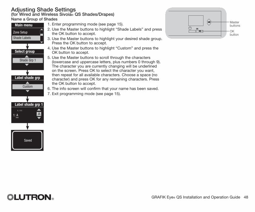
® GRAFIK Eye® QS Installation and Operation Guide 48
Adjusting Shade Settings (for Wired and Wireless Sivoia® QS Shades/Drapes)Name a Group of Shades
1. Enter programming mode (see page 15).2. Use the Master buttons to highlight “Shade Labels” and press
the OK button to accept.3. Use the Master buttons to highlight your desired shade group.
Press the OK button to accept.4. Use the Master buttons to highlight “Custom” and press the
OK button to accept.5. Use the Master buttons to scroll through the characters
(lowercase and uppercase letters, plus numbers 0 through 9). The character you are currently changing will be underlined on the screen. Press OK to select the character you want, then repeat for all available characters. Choose a space (no character) and press OK for any remaining characters. Press the OK button to accept.
6. The info screen will confirm that your name has been saved.7. Exit programming mode (see page 15).
Main menu
Zone Setup
Shade Labels
Select group
Shade Grp 1
Label shade grp
Custom
Label shade grp 1
1: A
1 / 11
OK
1 2 3 4 5 6
A
Master buttons
OK button
Saved
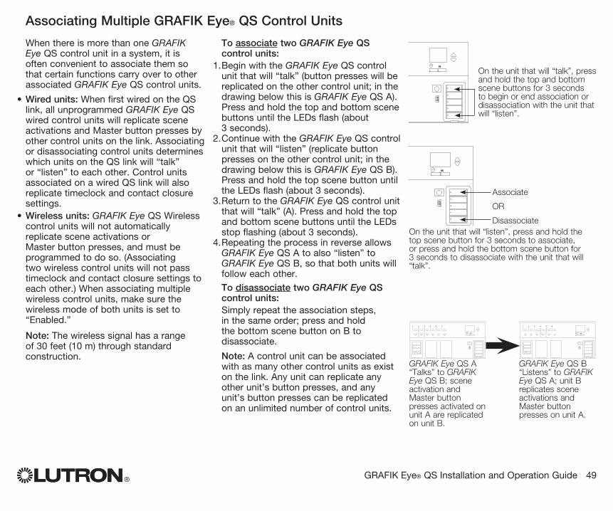
® GRAFIK Eye® QS Installation and Operation Guide 49
OK
1 2 3 4 5 6
OK
1 2 3 4 5 6
GRAFIK Eye QS A“Talks” to GRAFIK Eye QS B; scene activation and Master button presses activated on unit A are replicated on unit B.
GRAFIK Eye QS B“Listens” to GRAFIK Eye QS A; unit B replicates scene activations and Master button presses on unit A.
When there is more than one GRAFIK Eye QS control unit in a system, it is often convenient to associate them so that certain functions carry over to other associated GRAFIK Eye QS control units.
• Wired units: When first wired on the QS link, all unprogrammed GRAFIK Eye QS wired control units will replicate scene activations and Master button presses by other control units on the link. Associating or disassociating control units determines which units on the QS link will “talk” or “listen” to each other. Control units associated on a wired QS link will also replicate timeclock and contact closure settings.
• Wireless units: GRAFIK Eye QS Wireless control units will not automatically replicate scene activations or Master button presses, and must be programmed to do so. (Associating two wireless control units will not pass timeclock and contact closure settings to each other.) When associating multiple wireless control units, make sure the wireless mode of both units is set to “Enabled.”
Note: The wireless signal has a range of 30 feet (10 m) through standard construction.
To associate two GRAFIK Eye QS control units:
1. Begin with the GRAFIK Eye QS control unit that will “talk” (button presses will be replicated on the other control unit; in the drawing below this is GRAFIK Eye QS A). Press and hold the top and bottom scene buttons until the LEDs flash (about 3 seconds).
2. Continue with the GRAFIK Eye QS control unit that will “listen” (replicate button presses on the other control unit; in the drawing below this is GRAFIK Eye QS B). Press and hold the top scene button until the LEDs flash (about 3 seconds).
3. Return to the GRAFIK Eye QS control unit that will “talk” (A). Press and hold the top and bottom scene buttons until the LEDs stop flashing (about 3 seconds).
4. Repeating the process in reverse allows GRAFIK Eye QS A to also “listen” to GRAFIK Eye QS B, so that both units will follow each other.
To disassociate two GRAFIK Eye QS control units:Simply repeat the association steps, in the same order; press and hold the bottom scene button on B to disassociate.
Note: A control unit can be associated with as many other control units as exist on the link. Any unit can replicate any other unit’s button presses, and any unit’s button presses can be replicated on an unlimited number of control units.
Associating Multiple GRAFIK Eye® QS Control Units
OK
1 2 3 4 5 6
On the unit that will “talk”, press and hold the top and bottom scene buttons for 3 seconds to begin or end association or disassociation with the unit that will “listen”.
OK
1 2 3 4 5 6
On the unit that will “listen”, press and hold the top scene button for 3 seconds to associate, or press and hold the bottom scene button for 3 seconds to disassociate with the unit that will “talk”.
Associate
OR
Disassociate

® GRAFIK Eye® QS Installation and Operation Guide 50
Diagnostics and Special SettingsEnable/Disable Timeclock
The timeclock can be enabled or disabled as desired.1. Enter programming mode (see page 15),
select “Timeclock,” and select “Enable/Disable”. Press the OK button to accept.
2. Use the Master buttons to highlight either “Enabled” or “Disabled”. Press the OK button to accept.
3. The info screen will confirm that your setting has been saved.
4. Exit programming mode (see page 15).
OK
1 2 3 4 5 6
Master buttons
OK button
Saved
Monday
Timeclock
Enabled
Enable/Disable IR Receiver The IR receiver can be enabled or disabled as desired.
1. Enter programming mode (see page 15) and select “IR receiver”. Press the OK button to accept.
2. Use the Master buttons to highlight either “Enabled” or “Disabled”. Press the OK button to accept.
3. The info screen will confirm that your setting has been saved.
4. Exit programming mode (see page 15).Saved
Monday
IR receiver
Disabled
Enable/Disable Backlighting The backlighting on the info screen can be enabled or
disabled as desired.1. Enter programming mode (see page
15) and select “Backlighting”. Press the OK button to accept.
2. Use the Master buttons to highlight either “Enabled” or “Disabled”. Press the OK button to accept.
3. The info screen will confirm that your setting has been saved.
4. Exit programming mode (see page 15).
Saved
Monday
Backlighting
Enabled
Diagnostics If you are having trouble with your control unit and call
Lutron Technical Support, you may be asked for diagnostic information about your unit.
1. Enter programming mode (see page 15) and select “Diagnostics”. Press the OK button to accept.
2. Use the Master buttons to highlight the option that will display the required information. The info screen can display the device serial number, link information, code version, or USB status. There is also an option to reset the USB connection (do this only if asked to by Lutron Technical Support).
4. Exit programming mode (see page 15).
Link info
Diagnostics
Device SN
Link Info
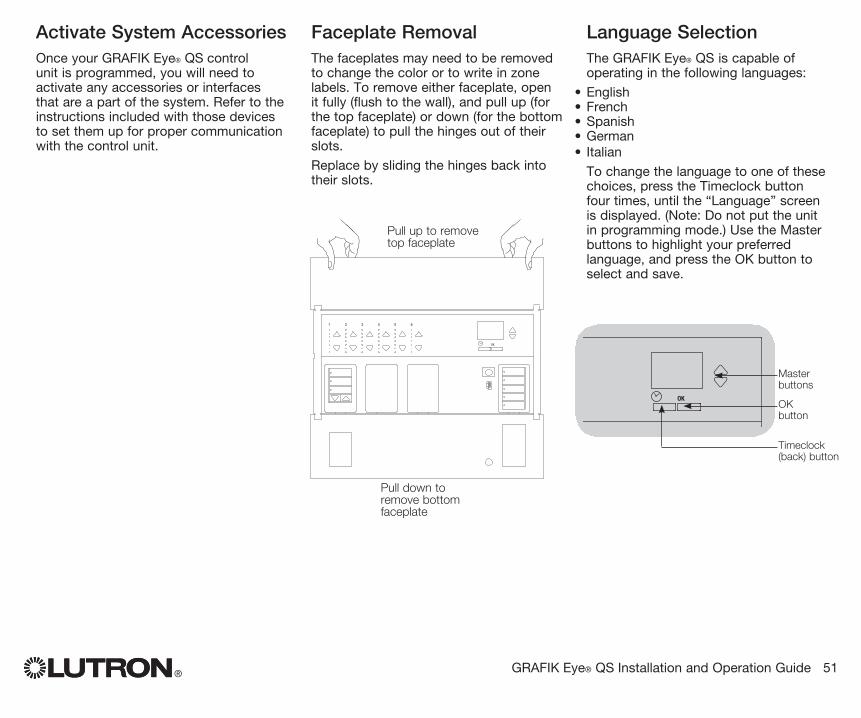
Activate System AccessoriesOnce your GRAFIK Eye® QS control unit is programmed, you will need to activate any accessories or interfaces that are a part of the system. Refer to the instructions included with those devices to set them up for proper communication with the control unit.
Faceplate RemovalThe faceplates may need to be removed to change the color or to write in zone labels. To remove either faceplate, open it fully (flush to the wall), and pull up (for the top faceplate) or down (for the bottom faceplate) to pull the hinges out of their slots.
Replace by sliding the hinges back into their slots.
Language SelectionThe GRAFIK Eye® QS is capable of operating in the following languages:
• English• French• Spanish• German• Italian
To change the language to one of these choices, press the Timeclock button four times, until the “Language” screen is displayed. (Note: Do not put the unit in programming mode.) Use the Master buttons to highlight your preferred language, and press the OK button to select and save.
®
OK
1 2 3 4 5 6
Pull up to remove top faceplate
Pull down to remove bottom faceplate
GRAFIK Eye® QS Installation and Operation Guide 51
OK
1 2 3 4 5 6
Master buttons
OK button
Timeclock (back) button
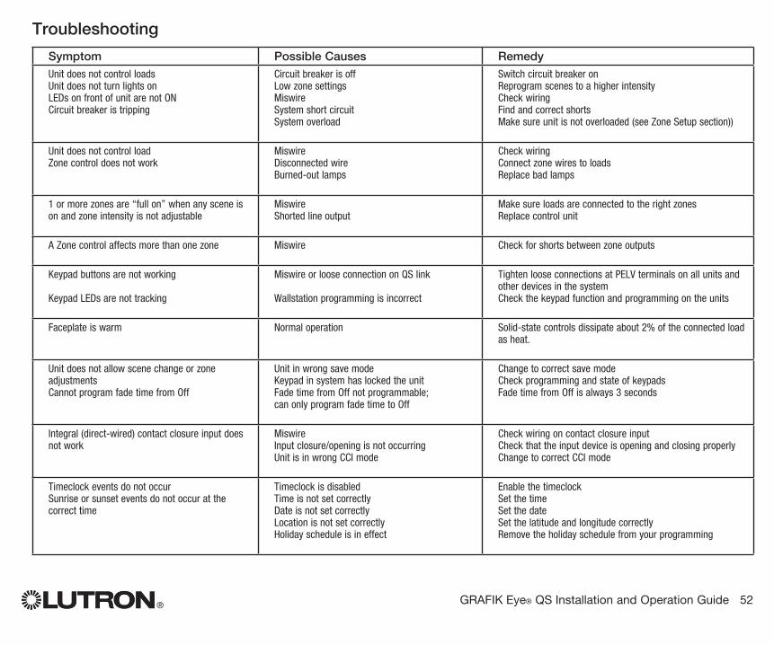
Symptom Possible Causes RemedyUnit does not control loadsUnit does not turn lights onLEDs on front of unit are not ONCircuit breaker is tripping
Circuit breaker is offLow zone settingsMiswireSystem short circuitSystem overload
Switch circuit breaker onReprogram scenes to a higher intensityCheck wiringFind and correct shortsMake sure unit is not overloaded (see Zone Setup section))
Unit does not control loadZone control does not work
MiswireDisconnected wireBurned-out lamps
Check wiringConnect zone wires to loadsReplace bad lamps
1 or more zones are “full on” when any scene is on and zone intensity is not adjustable
MiswireShorted line output
Make sure loads are connected to the right zonesReplace control unit
A Zone control affects more than one zone Miswire Check for shorts between zone outputs
Keypad buttons are not working
Keypad LEDs are not tracking
Miswire or loose connection on QS link
Wallstation programming is incorrect
Tighten loose connections at PELV terminals on all units and other devices in the systemCheck the keypad function and programming on the units
Faceplate is warm Normal operation Solid-state controls dissipate about 2% of the connected load as heat.
Unit does not allow scene change or zone adjustmentsCannot program fade time from Off
Unit in wrong save modeKeypad in system has locked the unitFade time from Off not programmable; can only program fade time to Off
Change to correct save modeCheck programming and state of keypadsFade time from Off is always 3 seconds
Integral (direct-wired) contact closure input does not work
MiswireInput closure/opening is not occurringUnit is in wrong CCI mode
Check wiring on contact closure inputCheck that the input device is opening and closing properlyChange to correct CCI mode
Timeclock events do not occurSunrise or sunset events do not occur at the correct time
Timeclock is disabledTime is not set correctlyDate is not set correctlyLocation is not set correctlyHoliday schedule is in effect
Enable the timeclockSet the timeSet the dateSet the latitude and longitude correctlyRemove the holiday schedule from your programming
® GRAFIK Eye® QS Installation and Operation Guide 52
Troubleshooting
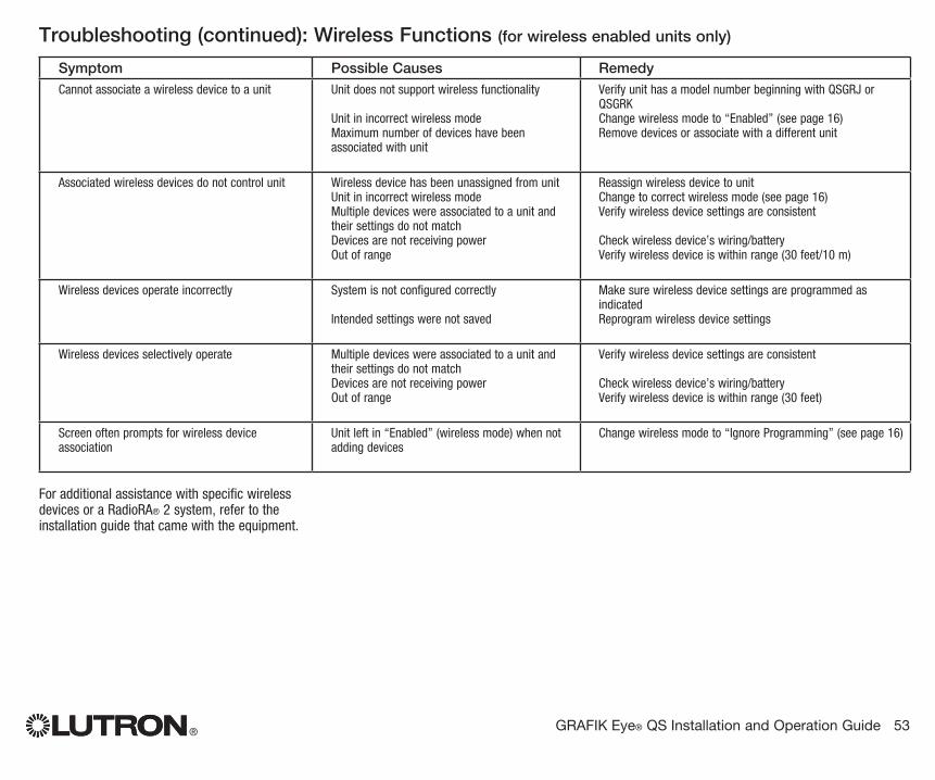
® GRAFIK Eye® QS Installation and Operation Guide 53
Symptom Possible Causes RemedyCannot associate a wireless device to a unit Unit does not support wireless functionality
Unit in incorrect wireless modeMaximum number of devices have been associated with unit
Verify unit has a model number beginning with QSGRJ or QSGRKChange wireless mode to “Enabled” (see page 16)Remove devices or associate with a different unit
Associated wireless devices do not control unit Wireless device has been unassigned from unitUnit in incorrect wireless modeMultiple devices were associated to a unit and their settings do not matchDevices are not receiving powerOut of range
Reassign wireless device to unitChange to correct wireless mode (see page 16)Verify wireless device settings are consistent
Check wireless device’s wiring/batteryVerify wireless device is within range (30 feet/10 m)
Wireless devices operate incorrectly System is not configured correctly
Intended settings were not saved
Make sure wireless device settings are programmed as indicatedReprogram wireless device settings
Wireless devices selectively operate Multiple devices were associated to a unit and their settings do not matchDevices are not receiving powerOut of range
Verify wireless device settings are consistent
Check wireless device’s wiring/batteryVerify wireless device is within range (30 feet)
Screen often prompts for wireless device association
Unit left in “Enabled” (wireless mode) when not adding devices
Change wireless mode to “Ignore Programming” (see page 16)
For additional assistance with specific wireless devices or a RadioRA® 2 system, refer to the installation guide that came with the equipment.
Troubleshooting (continued): Wireless Functions (for wireless enabled units only)
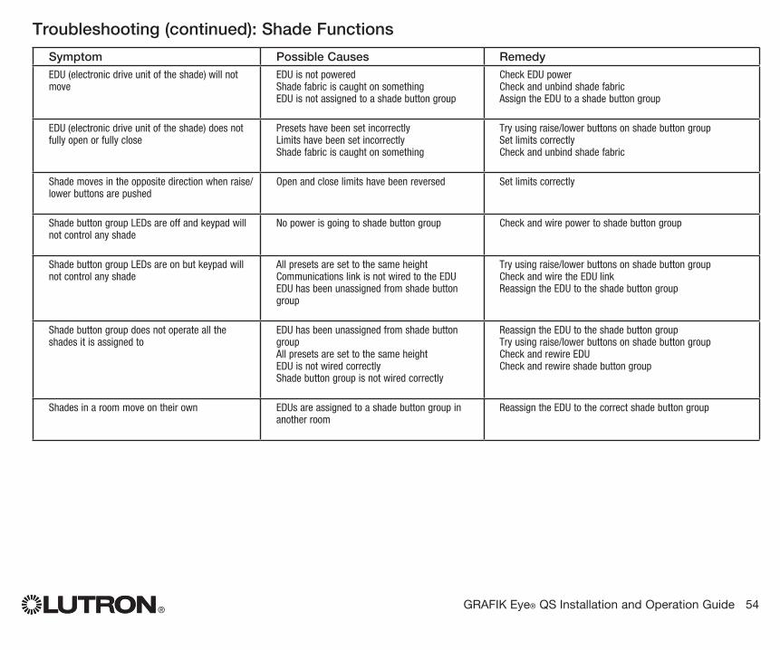
® GRAFIK Eye® QS Installation and Operation Guide 54
Symptom Possible Causes RemedyEDU (electronic drive unit of the shade) will not move
EDU is not poweredShade fabric is caught on somethingEDU is not assigned to a shade button group
Check EDU powerCheck and unbind shade fabricAssign the EDU to a shade button group
EDU (electronic drive unit of the shade) does not fully open or fully close
Presets have been set incorrectlyLimits have been set incorrectlyShade fabric is caught on something
Try using raise/lower buttons on shade button groupSet limits correctlyCheck and unbind shade fabric
Shade moves in the opposite direction when raise/lower buttons are pushed
Open and close limits have been reversed Set limits correctly
Shade button group LEDs are off and keypad will not control any shade
No power is going to shade button group Check and wire power to shade button group
Shade button group LEDs are on but keypad will not control any shade
All presets are set to the same heightCommunications link is not wired to the EDUEDU has been unassigned from shade button group
Try using raise/lower buttons on shade button groupCheck and wire the EDU linkReassign the EDU to the shade button group
Shade button group does not operate all the shades it is assigned to
EDU has been unassigned from shade button groupAll presets are set to the same heightEDU is not wired correctlyShade button group is not wired correctly
Reassign the EDU to the shade button groupTry using raise/lower buttons on shade button groupCheck and rewire EDUCheck and rewire shade button group
Shades in a room move on their own EDUs are assigned to a shade button group in another room
Reassign the EDU to the correct shade button group
Troubleshooting (continued): Shade Functions
®
Lutron Electronics Co., Inc.One Year Limited Warranty Foraperiodofoneyearfromthedateofpurchase,andsubjecttotheexclusionsandrestrictionsdescribedbelow,Lutronwarrantseachnewunittobefreefrommanufacturingdefects.Lutronwill,atitsoption,eitherrepairthedefectiveunitorissueacreditequaltothepurchasepriceofthedefectiveunittotheCustomeragainstthepurchasepriceofcomparablereplacementpartpurchasedfromLutron.ReplacementsfortheunitprovidedbyLutronor,atitssolediscretion,anapprovedvendormaybenew,used,repaired,reconditioned,and/ormadebyadifferentmanufacturer. IftheunitiscommissionedbyLutronoraLutronapprovedthirdpartyaspartofaLutroncommissionedlightingcontrolsystem,thetermofthiswarrantywillbeextended,andanycreditsagainstthecostofreplacementpartswillbeprorated,inaccordancewiththewarrantyissuedwiththecommissionedsystem,exceptthatthetermoftheunit’swarrantytermwillbemeasuredfromthedateofitscommissioning.EXCLUSIONS AND RESTRICTIONS ThisWarrantydoesnotcover,andLutronanditssuppliersarenotresponsiblefor:1. Damage,malfunctionorinoperabilitydiagnosedbyLutronor
aLutronapprovedthirdpartyascausedbynormalwearandtear,abuse,misuse,incorrectinstallation,neglect,accident,interferenceorenvironmentalfactors,suchas(a)useofincorrectlinevoltages,fusesorcircuitbreakers;(b)failuretoinstall,maintainandoperatetheunitpursuanttotheoperatinginstructionsprovidedbyLutronandtheapplicableprovisionsoftheNationalElectricalCodeandoftheSafetyStandardsofUnderwriter’sLaboratories;(c)useofincompatibledevicesoraccessories;(d)improperorinsufficientventilation;(e)unauthorizedrepairsoradjustments;(f)vandalism;or(g)anactofGod,suchasfire,lightning,flooding,tornado,earthquake,hurricaneorotherproblemsbeyondLutron’scontrol.
2. On-sitelaborcoststodiagnoseissueswith,andtoremove,repair,replace,adjust,reinstalland/orreprogramtheunitoranyofitscomponents.
3. Equipmentandpartsexternaltotheunit,includingthosesoldorsuppliedbyLutron(whichmaybecoveredbyaseparatewarranty).
4. Thecostofrepairingorreplacingotherpropertythatisdamagedwhentheunitdoesnotworkproperly,evenifthedamagewascausedbytheunit.
EXCEPTASEXPRESSLYPROVIDEDINTHISWARRANTY,THEREARENOEXPRESSORIMPLIEDWARRANTIESOFANYTYPE,INCLUDINGANYIMPLIEDWARRANTIESOFFITNESSFORAPARTICULARPURPOSEORMERCHANTABILITY.LUTRONDOESNOTWARRANTTHATTHEUNITWILLOPERATEWITHOUTINTERRUPTIONORBEERRORFREE. NOLUTRONAGENT,EMPLOYEEORREPRESENTATIVEHASANYAUTHORITYTOBINDLUTRONTOANYAFFIRMATION,REPRESENTATIONORWARRANTYCONCERNINGTHEUNIT.UNLESSANAFFIRMATION,REPRESENTATIONORWARRANTYMADEBYANAGENT,EMPLOYEEORREPRESENTATIVEISSPECIFICALLYINCLUDEDHEREIN,ORINSTANDARDPRINTEDMATERIALSPROVIDEDBYLUTRON,ITDOESNOTFORMAPARTOFTHEBASISOFANYBARGAINBETWEENLUTRONANDCUSTOMERANDWILLNOTINANYWAYBEENFORCEABLEBYCUSTOMER. INNOEVENTWILLLUTRONORANYOTHERPARTYBELIABLEFOREXEMPLARY,CONSEQUENTIAL,INCIDENTALORSPECIALDAMAGES(INCLUDING,BUTNOTLIMITEDTO,
DAMAGESFORLOSSOFPROFITS,CONFIDENTIALOROTHERINFORMATION,ORPRIVACY;BUSINESSINTERRUPTION;PERSONALINJURY;FAILURETOMEETANYDUTY,INCLUDINGOFGOODFAITHOROFREASONABLECARE;NEGLIGENCE,ORANYOTHERPECUNIARYOROTHERLOSSWHATSOEVER),NORFORANYREPAIRWORKUNDERTAKENWITHOUTLUTRON’SWRITTENCONSENTARISINGOUTOFORINANYWAYRELATEDTOTHEINSTALLATION,DEINSTALLATION,USEOFORINABILITYTOUSETHEUNITOROTHERWISEUNDERORINCONNECTIONWITHANYPROVISIONOFTHISWARRANTY,ORANYAGREEMENTINCORPORATINGTHISWARRANTY,EVENINTHEEVENTOFTHEFAULT,TORT(INCLUDINGNEGLIGENCE),STRICTLIABILITY,BREACHOFCONTRACTORBREACHOFWARRANTYOFLUTRONORANYSUPPLIER,ANDEVENIFLUTRONORANYOTHERPARTYWASADVISEDOFTHEPOSSIBILITYOFSUCHDAMAGES. NOTWITHSTANDINGANYDAMAGESTHATCUSTOMERMIGHTINCURFORANYREASONWHATSOEVER(INCLUDING,WITHOUTLIMITATION,ALLDIRECTDAMAGESANDALLDAMAGESLISTEDABOVE),THEENTIRELIABILITYOFLUTRONANDOFALLOTHERPARTIESUNDERTHISWARRANTYONANYCLAIMFORDAMAGESARISINGOUTOFORINCONNECTIONWITHTHEMANUFACTURE,SALE,INSTALLATION,DELIVERY,USE,REPAIR,ORREPLACEMENTOFTHEUNIT,ORANYAGREEMENTINCORPORATINGTHISWARRANTY,ANDCUSTOMER’SSOLEREMEDYFORTHEFOREGOING,WILLBELIMITEDTOTHEAMOUNTPAIDTOLUTRONBYCUSTOMERFORTHEUNIT.THEFOREGOINGLIMITATIONS,EXCLUSIONSANDDISCLAIMERSWILLAPPLYTOTHEMAXIMUMEXTENTALLOWEDBYAPPLICABLELAW,EVENIFANYREMEDYFAILSITSESSENTIALPURPOSE.TO MAKE A WARRANTY CLAIM Tomakeawarrantyclaim,promptlynotifyLutronwithinthewarrantyperioddescribedabovebycallingtheLutronTechnicalSupportCenterat(800)523-9466.Lutron,initssolediscretion,willdeterminewhataction,ifany,isrequiredunderthiswarranty.TobetterenableLutrontoaddressawarrantyclaim,havetheunit’sserialandmodelnumbersavailablewhenmakingthecall.IfLutron,initssolediscretion,determinesthatanon-sitevisitorotherremedialactionisnecessary,LutronmaysendaLutronServicesCo.representativeorcoordinatethedispatchofarepresentativefromaLutronapprovedvendortoCustomer’ssite,and/orcoordinateawarrantyservicecallbetweenCustomerandaLutronapprovedvendor. Thiswarrantygivesyouspecificlegalrights,andyoumayalsohaveotherrightswhichvaryfromstatetostate.Somestatesdonotallowlimitationsonhowlonganimpliedwarrantylasts,sotheabovelimitationmaynotapplytoyou.Somestatesdonotallowtheexclusionorlimitationofincidentalorconsequentialdamages,sotheabovelimitationorexclusionmaynotapplytoyou. TheseproductsmaybecoveredunderoneormoreofthefollowingU.S.patents:5,191,265;5,430,356;5,463,286;5,838,226;5,848,054;5,905,442;5,949,200;5,982,103;6,091,205;6,188,181;6,380,692;6,687,487;6,803,728;D546,294;D547,733;D547,734;D550,163;D550,164;D550,165;D550,166;D551,179;D552,042;andcorrespondingforeignpatents.OtherU.S.andforeignpatentsmaybepending. NECisaregisteredtrademarkoftheNationalFireProtectionAssociation,Quincy,Massachusetts. Lutron,thesunburstlogo,Sivoia,Hi-lume,Eco-10,Tu-Wire,RadioRA,Pico,seeTouch,andGRAFIKEyeareregisteredtrademarksandRadioPowrSavrisatrademarkofLutronElectronicsCo.,Inc. ©2010LutronElectronicsCo.,Inc.
Internet: www.lutron.comE-mail: [email protected]
WORLD HEADQUARTERSUSALutron Electronics Co., Inc.7200 Suter Road, Coopersburg, PA 18036-1299TEL +1.610.282.3800FAX +1.610.282.1243Toll-Free 1.888.LUTRON1Technical Support 1.800.523.9466
North and South America Technical HotlinesUSA, Canada, Caribbean: 1.800.523.9466Mexico: +1.888.235.2910Central/South America: +1.610.282.6701
EUROPEAN HEADQUARTERSUnited KingdomLutron EA Ltd.6 Sovereign Close, London, E1W 3JF United KingdomTEL +44.(0)20.7702.0657FAX +44.(0)20.7480.6899FREEPHONE (UK) 0800.282.107Technical support +44.(0)20.7680.4481
ASIAN HEADQUARTERSSingaporeLutron GL Ltd. 15 Hoe Chiang Road, #07-03 Euro Asia Centre, Singapore 089316TEL +65.6220.4666FAX +65.6220.4333
Asia Technical HotlinesNorthern China: 10.800.712.1536Southern China: 10.800.120.1536Hong Kong: 800.901.849Indonesia: 001.803.011.3994Japan: +81.3.5575.8411Macau: 0800.401Singapore: 800.120.4491Taiwan: 00.801.137.737Thailand: 001.800.120.665853Other countries: +65.6220.4666
Warranty
Lutron Electronics Co., Inc.Made and printed in U.S.A.P/N 032-305 Rev. A 02.15.09
Contact Information