installation and setting up instructions for the type 900 ...pdfs.findtheneedle.co.uk/40719.pdf ·...
TRANSCRIPT

Installation and Setting up Instructions for the
Type 900
Dual Channel Trip Amplifier
Hawker Electronics Limited O&M 85
57 The Avenue, Issue D Rubery Industrial Estate, April 2016 Birmingham, B45 9AL Tel: +44(0)121-453-8911 Fax: +44(0)121-453-3777 www.hawker-electronics.co.uk e-mail: [email protected]
This product has been designed and complies to the relevant standards as listed in its certificate of conformity. The installer/user must ensure system compliance.
The Crossed-out bin symbol, placed on the product, reminds you of the need to dispose of the product correctly at the end of its life.

1.0 General Description
The Type 900 is a dual channel trip amplifier which accepts a signal from a vessel
mounted sensor and operates individual relays anywhere over its input range. When in
‘run’ mode the 4 digit LCD gives a real time reading of the signal from the
transmitter. When in ‘Programme’ mode the LCD provides the user with a menu
system to precisely set the relay ON/OFF points and other parameters. Programming
is achieved via 4 facia push buttons.
Applications include Alarm, Control, Pumping IN and Pumping OUT, fail safe HIGH
and/or fail safe LOW. The Type 900 provides DC power for the input sensor which is
current limited. The input signal is normally a mA current direct from a sensor.
Important Information This equipment should only be specified, installed and commissioned by suitably
qualified persons. This product contains no user serviceable parts, removing the
product from its enclosure, modification or using other than outlined in the
manufacturers guidelines in any way invalidates the warranty and safety features. The
electrical installation should comply with local regulations. Ensure the correct
instructions are used for the version fitted.
2.0 Mounting, Electrical Installation and Connection
The Type 900 can be mounted using the snap fastener DIN rail or by a screw
fastenings using the hole slots on the lower left and upper right external corners of the
enclosure. The product is intended to be mounted with the power terminals at the
bottom of the enclosure. An air gap of 10mm minimum should be available around
the enclosure perimeter for proper air circulation to prevent overheating.
The Type 900 should not be mounted close to heat sources; electrical noisy apparatus
e.g. welding machines and inverter drives; locations subject to strong vibrations or
shocks; dusty or corrosive gas environments; outdoors in direct sunlight or high
humidity areas.
The crossed out bin symbol placed on the product reminds you of the need to dispose
of the product correctly at the of its life.
Maintenance is not required for this product other than periodic testing if demanded
by the application. External cleaning can be preformed using a mild detergent care
should be taken not to clean the product with aggressive substances they may damage
the enclosure, terminals or label. Cleaning should be performed with the power to live
connections disconnected by means of isolation.
1.

2
2.1 Connection
The Type 900 is available as a DC or AC version (factory set). The lower terminal block is
for connection of the users power supply input to the product and the Type 900 volt free
relay contacts outputs. The upper terminal is the connection to the input sensor.
The power and relay cables can be either single cores or multi core, this product does not
require an earth connection. All cables should be rated electrically suitable (see data
specifications) and mechanically robust enough for the application. The input sensor cable
will normally be pre-fitted to the sensor itself. If this cable is screened the screen can be
connected to the signal 0V terminal if required. The screen should be connected at one end
only and if possible at the controller end.
The power supply to the 900 should be via a local external isolator and fuse. This is also
applicable to the relay contacts especially when switching hazardous voltages. This
enables the 900 to be safely disconnected if required, as well as providing over current
protection.
Caution risk of danger symbol. This symbol if shown on the product label indicates the terminals
marked 'supply' and 'relay' may contain hazardous voltages, depending on the model and users application.
Identify and Isolate before connecting or disconnecting.
The installation should comply with local regulations.
Fig 1 Wiring Connections
Always confirm the connections with the products terminal block label before connecting
as positions may vary depending on model. The Type 900 is available as a DC or AC
powered version which is specified on order.
3
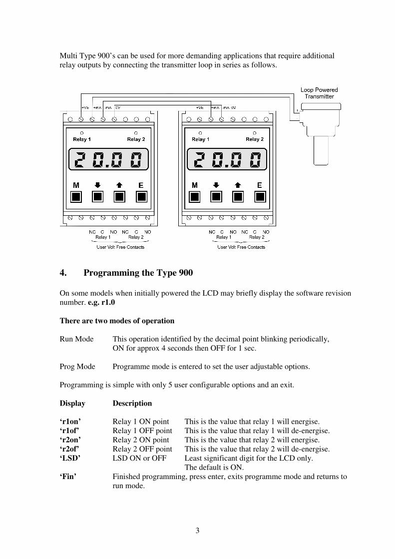
Multi Type 900’s can be used for more demanding applications that require additional
relay outputs by connecting the transmitter loop in series as follows.
4. Programming the Type 900
On some models when initially powered the LCD may briefly display the software revision
number. e.g. r1.0
There are two modes of operation
Run Mode This operation identified by the decimal point blinking periodically,
ON for approx 4 seconds then OFF for 1 sec.
Prog Mode Programme mode is entered to set the user adjustable options.
Programming is simple with only 5 user configurable options and an exit.
Display Description
‘r1on’ Relay 1 ON point This is the value that relay 1 will energise.
‘r1of’ Relay 1 OFF point This is the value that relay 1 will de-energise.
‘r2on’ Relay 2 ON point This is the value that relay 2 will energise.
‘r2of’ Relay 2 OFF point This is the value that relay 2 will de-energise.
‘LSD’ LSD ON or OFF Least significant digit for the LCD only.
The default is ON.
‘Fin’ Finished programming, press enter, exits programme mode and returns to
run mode.
4
Programming the Type 900
1. Enter programme mode by pressing the ‘M’ key for approx 5 seconds. Each of the
6 menus can be accessed in the order above by pressing and releasing the ‘M’ key.
This is an example of setting Relay 1 ON point
Enter programme mode as in (1) above.
The LCD will display ‘r1on’, press ‘E’, the current value will be displayed, use the up and
down keys to enter the new value, press ’E’ when done to enter new value, the LCD will
briefly display ‘done’ then go back to the main menu and display ‘r1on’. Press and release
‘M’ until the LCD reads ‘Fin’, press ‘E’ this will exit programme mode and return to ‘run’
mode.
This can be repeated for each relay as necessary.
The LSD menu option (least significant digit)
The real time input signal display default is 4 digits and when the relay ON/OFF points are
programmed it is always 4 digits. This gives the best possible resolution and control of the
relays, i.e. their ON/OFF operation will be exactly as programmed to the least significant
digit (00.01mA). However sometimes due to application turbulence it may be less of a
distraction to display only 3 digits, this is achieved by turning the LSD OFF (UP key
toggles in the programme menu). Under these conditions it must be remembered that the
relays will operate at the programmed values and not the 3 digit value. This only effects
the display and not the relay set points.
Additional Notes on Programming
When adjusting the ON/OFF points the counter rolls from min to max and vice verse this
saves time.
The counter use’s a speed key function that increases the speed it is counting at if the UP or
DOWN button is continually pressed for a few seconds or more. When the counter is
getting close to the desired value release the key and then use individual presses and
releases for precision adjustment.
User parameters are stored in non volatile memory so will be retained if the Type 900 loses
power.
If power is lost during a cycle reapplying power will be treated as an initial power up i.e.
the input will be compared with the relay set points and the cycle restarted.
The fail safe of the Type 900 is automatically determined by the relay set points. If the ON
point is greater then the OFF point it is failsafe LOW, if the OFF point it is greater than the
ON point it is fail safe HIGH.
5
Errors
‘Err’ message This is only displayed when in run mode and there is a problem with
the relays. The most common cause is one or both of the relays ON and
OFF points are the same.
dp not blinking If the decimal point is not blinking the unit may have been
unintentionally left in program mode. Press the ‘M’ key repeat until
‘Fin’ is displayed the press the ‘E’ key, this will exit programme mode
Alternatively momentarily turn the power OFF and then back ON.
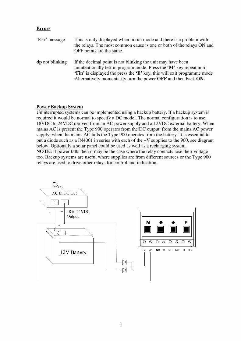
Power Backup System
Uninterrupted systems can be implemented using a backup battery, If a backup system is
required it would be normal to specify a DC model. The normal configuration is to use
18VDC to 24VDC derived from an AC power supply and a 12VDC external battery. When
mains AC is present the Type 900 operates from the DC output from the mains AC power
supply, when the mains AC fails the Type 900 operates from the battery. It is essential to
put a diode such as a IN4001 in series with each of the +V supplies to the 900, see diagram
below. Optionally a solar panel could be used as well as a recharging system.
NOTE: If power falls then it may be the case where the relay contacts lose their voltage
too. Backup systems are useful where supplies are from different sources or the Type 900
relays are used to drive other relays for control and indication.
6