installation and setting-up instructions spare parts list
TRANSCRIPT

Installation and Setting-Up InstructionsSpare Parts List
Contents :
1 TECHNICAL DATA
2 CONSTRUCTION AND OPERATION
3 INSTALLATION
4 SETTING-UP
5 MAINTENANCE
DOCUMENTSTechnical Specifications : G365Installation and Setting-Up Instructions : G365AV We reserve the right for technical modifications without prior notice.
SATRON PASVE DUAL Mounting & Service Valve
G365AVMan.rev.2
2012-11-15
The sensor-specific spare part list will be delivered with theorder.
PASVE® pH is the registered trademark of Satron Instruments Inc.
Satron Instruments Inc.P.O. Box 22, FIN-33901 Tampere
Tel. +358 207 464 800Telefax +358 207 464 801
www.satron.com, [email protected]

TECHNICAL SPECIFICATIONS
Applicable pH sensorsSee the technical specification SATRON PASVEDUAL Mounting and Service Valve G365
Max. operating pressure/temperature40 bar, 250 °C, (see the appended table). Min.operating temp. -50°C.Sensor-specific limitations should also be taken intoaccount in applications.
1. TECHNICAL DATA
PASVE® DUAL is mounting and service valve fortwo pH sensors of diameter 12 mm. It can be usedwith practically all pH sensors in this size category.
PASVE® DUAL allows the cleaning and calibrationof pH sensors without stopping the process. Whenrequired, this can be done automatically. To protectthe sensor in abrasive processes, it can be turned tothe measuring position only for the duration of theactual measurement.
PASVE® DUAL is available in a manually operatedtype or equipped with a pneumatic or electricactuator.
SATRON PASVE DUAL Mounting & Service ValveG365AV
2012-11-15
2
European Directive Information
ATEX directive (94/9/EC)Satron Instruments Inc. complies with the ATEXdirective.
European Pressure Equipment Directive (PED)(97/23/EC)- Sound Engineering Practice
Ambient temperature°C 70 85120
Temperature class
T6T5T4
Surface temperature
European Certification :
II 3 GDPressure / Temperature curve
ANSI150lbs
PN40/ANSI300lbs
-50 0 50 100 150 200 250°C
bar
10
20
30
40


SATRON PASVE DUAL Mounting & Service ValveG365AV
2012-11-15
Figure 2- 5 Dimensions, Pasve pH with electric actuator
320
150 75 200 90
6

SATRON PASVE DUAL Mounting & Service ValveG365AV
2012-11-15
PASVE pHT(Flow-through,threaded connection,mounting type/body T)
PASVE pHD(Flow-through, flange connection,mounting type/body D)
PASVE pHT
1" - NPT1,5" - NPT2" - NPT
77 92104
245
Thread Code (dimension K) B H
48 64 76
FlangeCode Type W ØD H H ANSI 1" 150 lbs 55 108 48 J ANSI 1" 300 lbs 55 124 48 U ANSI 2" 150 lbs 68 153 76 V ANSI 2" 300 lbs 68 165 76 G DN25 PN40 55 115 48 T DN50 PN40 68 165 76
PASVE pHD
400
(type
AS
)
270
K
ØD
230
300
250306
Ø140
BL
W
54
M10/15
H
Figure 2- 6 Dimensions, mounting types T and D (flow-through)
7
SATRON PASVE DUAL Mounting & Service ValveG365AV
2012-11-15
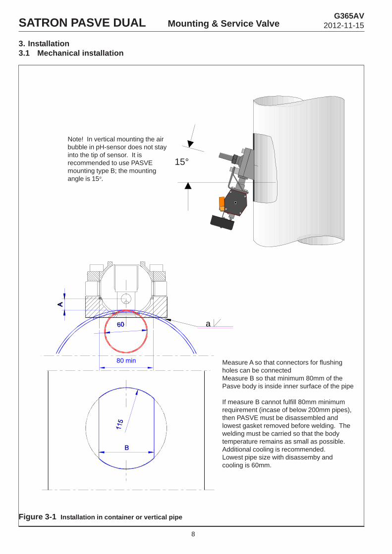
3. Installation3.1 Mechanical installation
Figure 3-1 Installation in container or vertical pipe
a
80 min Measure A so that connectors for flushingholes can be connectedMeasure B so that minimum 80mm of thePasve body is inside inner surface of the pipe
If measure B cannot fulfill 80mm minimumrequirement (incase of below 200mm pipes),then PASVE must be disassembled andlowest gasket removed before welding. Thewelding must be carried so that the bodytemperature remains as small as possible.Additional cooling is recommended.Lowest pipe size with disassemby andcooling is 60mm.
15°
Note! In vertical mounting the airbubble in pH-sensor does not stayinto the tip of sensor. It isrecommended to use PASVEmounting type B; the mountingangle is 15o.
8

SATRON PASVE DUAL Mounting & Service ValveG365AV
2012-11-15
Figure 3-2 Installation in horizontal pipe
Figure 3-3 Install body P in the pipe
Note! In horizontal mounting the air bubble in pH-sensordoes not stay into the tip of sensor. It is recommended touse the mounting angle 15o.
Machine the fbody of Pasve to the same diameter asthe pipe.Minimum pipe size is 70 mm.The welding must be carried so that the bodytemperature remains as small as possible.Additional cooling is recommended.
9
15°

SATRON PASVE DUAL Mounting & Service ValveG365AV
2012-11-15
Figure 3-4 Installation of Pasve pH body C in horizontal pipe
Figure 3-5 Welding of Pasve pH body C in horizontal pipe
10
SATRON PASVE DUAL Mounting & Service ValveG365AV
2012-11-15
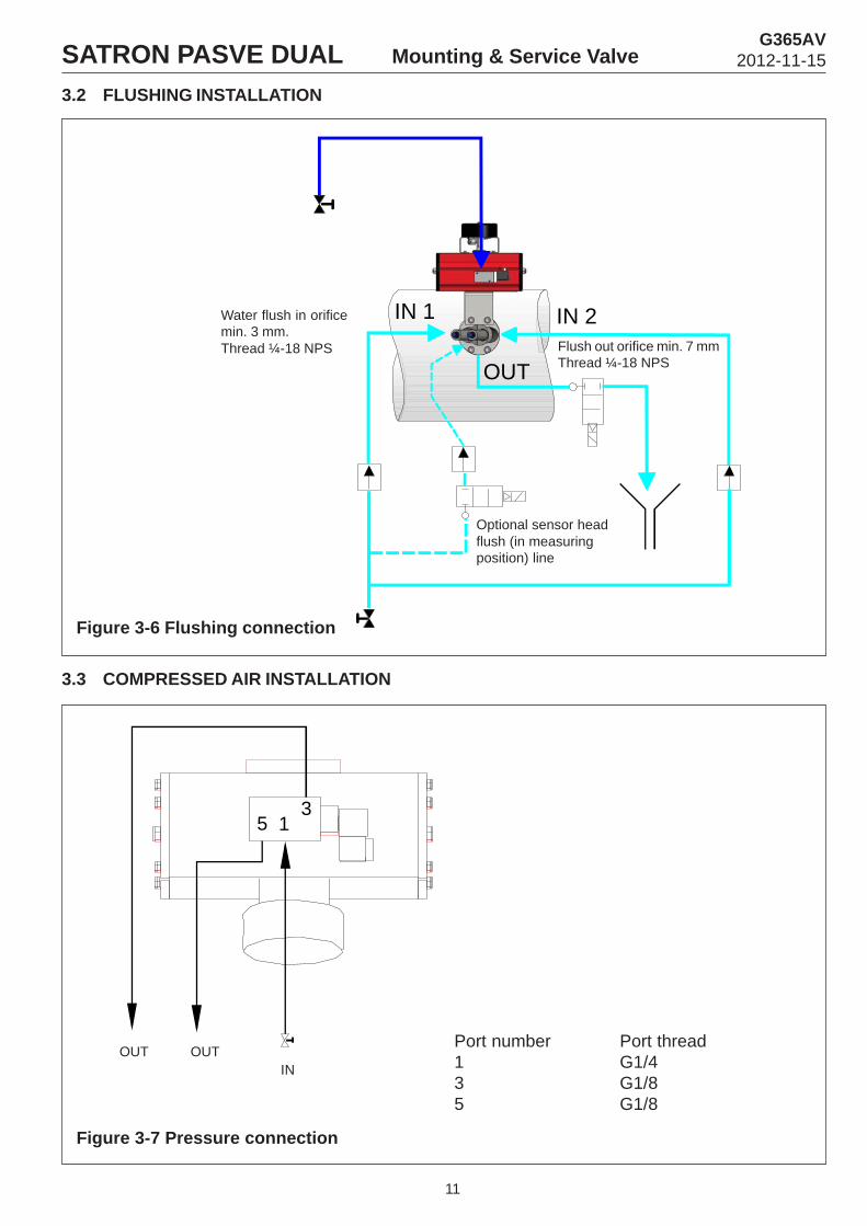
3.2 FLUSHING INSTALLATION
Figure 3-6 Flushing connection
Flush out orifice min. 7 mmThread ¼-18 NPS
Water flush in orificemin. 3 mm.Thread ¼-18 NPS
Optional sensor headflush (in measuringposition) line
3.3 COMPRESSED AIR INSTALLATION
153
Figure 3-7 Pressure connection
INOUT OUT
Port number Port thread1 G1/43 G1/85 G1/8
11
IN 1
OUT
IN 2

SATRON PASVE DUAL Mounting & Service ValveG365AV
2012-11-15
3.4 ELETRICAL CONNECTION
Figure 3-8 Solenoid valve connectionFigure 3-9 Removing the PLUG
junction box
12
Power
Kuva 3-10 Adjusting the junction boxposition
1
2
Open
1. Remove screw2. Open
1004354093
0.5 ... 1.5 mm 2
Pg9
Position selection3x90°
Tighten thescrew
Figure 3-11 Standard position switches
Figure 3-12 Inductive positionswitches, NS5002, NJ2-V3-N
1004354092
12

SATRON PASVE DUAL Mounting & Service ValveG365AV
2012-11-15
Figure 3-13 Electric actuator connection
13

bar
1. Shut-off valves A and B must be closed.Pressure P2=0
2. Always mount a sensor to the Pasve on theflushing position. One of the coupling of sensor isalways on a measuring position so you need tomake sure that there is a sensor or shut-off plugon both coupling of sensor , while turning thePasve.
SATRON PASVE DUAL Mounting & Service ValveG365AV
2012-11-15
Figure 4-1 pH sensor installation to Pasve pH mounting valve
Figure 4-2 pH sensor turning to measuring position
14
4 SETTING-UP
1. Shut-off valve C in the discharge pipemust be closed and the valve A or B in theinlet pipe is open. The pressure P1> P2
2. While using the Pasve make sure that thereis a sensor or shut-off plug on both couplingof sensor.
P2
A B
P1
P1
P2
CA B
P1

SATRON PASVE DUAL Mounting & Service ValveG365AV
2012-11-15
Figure 4-3 pH sensor flushing
Figure 4-4 When the process side flushing is needed?
15
1. When the sensor cleaning and flushing is neededin the measurement position without turning thesensor off.
2. When the hollow in the body is needed to becleaned off the possibly sedimented stuff.
3. When the foxhole in the body is needed to becleaned from the process liquid before turning theball.
Note! The pressure of the flushing liquid must be biggerthan the pressure of the process liquid. The temperatureof flushing liquid should be as near as possible to thetemperature of process liquid.Flushing should be made often for avoiding the blockingof flushing channel.
BC
A
P1
P2
P1
1. Turn PASVE pH ball to flushing position.Depending on the flush sensors valve A or Bopen, P1 > P2)
2. Open valve C for flushing. Let flushing water runthrough PASVE so long time that the sensor willbe clean.
3. Close the valve C4. Return PASVE pH ball to the measuring
position.
Many flushings rather than too few flushings!

Figure 5-1 Seals installation
1. Properly grease the seals by using e.g. almond oil.2. Place the smallest seal in the bottom groove. To ensure
correct alignment place the seals shorter chamferagainst the ball.
3. Press the seal as deep as possible into the groove withthe use of a finger. Then press the seal carefully allaround in place with a piece of wood. Since the finalpressing requires the use of force, be sure to apply auniform pressure on the piece of wood to avoiddamaging the seals.
wooden spatula
5 MAINTENANCE
SATRON PASVE DUAL Mounting & Service ValveG365AV
2012-11-15
16
Replacing the sealsRequired tools- M12 Allen key- piece of wood to press seal in groove- sharp, thin screwdriver to remove old seal- cleaning paper or cloth to clean the grooves
Procedure1. If PASVE is connected to process, make sure that the container/pipe is empty and unpressurized and, when necessary,flushed.2. Remove the sensor and valve ball (four M12 Allen screws). Make sure that the bearing parts do not drop off the shaft. WhenPasve is equipped with an actuator then it is very important that the other screws will not be opened, because the actuator settingscan otherwise be changed, see figure 5-1 part 18 or 24.3. Remove old sealing with screwdriver. Be careful not to scratch the metal surfaces. Once removed, the old seals will be damagedand useless.4. Clean the surface and sealing grooves carefully.5. Place the bottom (smallest) seal in its groove. Correct alignment: the seal's shorter chamfer against the ball, see figure 5-1.6. Press the seal with a finger as deep as possible in the groove. Then press the seal carefully home with a piece of wood. Sincethe final pressing requires the use of force, be sure to exert a uniform pressure on the piece of wood to avoid damaging the seal.7. Check the seals visually: they should be evenly in their grooves without any visible damage.8. Press new bearing strips and sleeves to the bottom of the shafts. Re-install the valve ball. Note mounting alignment, see thepicture Mounting on the back. Grease the Allen screws and tighten them by turns (60 Nm).9. Check the ball's movement and tightness. At first the ball will move quite stiffly, and moving the ball will require an additionallever arm and solid mounting (the valve must be firmly mounted either in the process or e.g. on a vice bench).
Other considerations:The type equipped with actuator has two groove seals,one of which is installed on the bearing ring to balance the bearing. Cut from the seal away a piece which is as big as the hole inthe bearing ring, see figure 5-1 part 26.

SATRON PASVE DUAL Mounting & Service ValveG365AV
2012-11-15
17
1
2
3
4
5
6
7
8
9
10
Part namePart no.
123456789
10
54426030T1015203T55097453282403T55238485547525T547526T5509754454751844547539
Allen screw M4x6 SFS2219 A4Lock bodyPull-out screwRetaining screw M4x6 DIN915 A4Locking elementPasve-springLock screwPull-out sleeveProtecting plugLever arm
Order code
Order code for locking piece assembly: (without lever arm, part no. 10)
Locking piece assembly, 65 deg T552382
Figure 5-2 Exploder view and part list, locking piece assembly
Part namePart no.
1111
2345679
10111213141516
T1015220T1015219T1015218T1015217
T1015213T1015214T55242880547534T101521557481326T101521654428138T547516T54752980547532800117255442824080011125
Body B, dualC, dualF, dualP, dual
Ball DUAL, AISI 316LBearing ring dualLock pinSealing ring 3Tube adapterCylindrical pin 10x24 ISO6325 A4Protective tubeAllen screw M12x30 SFS2219 A4Bearing stripBearing sleeveSealing ring 1o-ring Ø17x2,5 FPMAllen screw M12x30 SFS2219 A4o-ring Ø11x2,5 FPM
Order code
Pasve DUAL-valve assembly order codes:(without locking piece assembly and actuator assembly, material AISI316L)
Pasve DUAL- B200Pasve DUAL-C200Pasve DUAL-F0200Pasve DUAL- P200
MDUAL-B200MDUAL-C200MDUAL-F0200MDUAL-P200
Figure 5-3 Exploder view and part list, Pasve pH-U mounting valve

18
SATRON PASVE DUAL Mounting & Service ValveG365AV
2012-11-15
1234567
89
10
11121314
Retaining screw M4x6Limit stopSwitchHex screw M8x20 A4BraceBracePosition indicator stand. micro-switchPosition indicator Namur-switchMounting parts for position indicatorSolenoid valve Lucifer 341N 01
- Coil 2110 220V 50Hz (2W) or- (Coil 488980 3D 230V50Hz (2W))- Coil 488980 6J 110V60Hz (2W)- Coil 488980 C2 24VDC (2.5W)EEx me II T5-coil:- Coil 488980 3D 230V50Hz (2W)- Coil 488980 6J 110V60Hz (2W)- Coil 488980 C2 24VDC (2.5W)Solenoid valve EEx ia IIC T6- Coil 28 V DC 0.4 W EEx ia IIC T6
Actuator bracketAllen screw M12x70 A4SpacerActuator RC240 DA (double-action)Actuator RC240 SR (spring return)
53322400T550994T55310654220820T552946T55294782920022829200288292001982920031
82920033
8292003482920035
8292003782920038829200408292004282920043
T55294554428247T5510088292002082920021
Part no. Part name Order code
Figure 5-4 Exploder view and part list, actuator assembly
12
3
11
5
6
7
8
9 10
13
14
4
12
Order codes for actuator assembly: (without position indicator,parts no. 7 and 8 and without coil, part no. 10)
Actuator RC240DA + mounting partsActuator RC240SR + mounting parts
T553113T553116

SATRON PASVE DUAL Mounting & Service ValveG365AV
2012-11-15
19
Figure 5-5 Hard seal installation
o-ring 35.1x1.6
Hard seal :- PVDF- PTFE 50% / AISI316 50%
1. Set o-ring Ø35.1x1.6 to the groove in the bodybottom.
2. Set hard seal on the 0-ring in the body bottom. Besure that 0-ring is placed properly into the space ofthe seal collar and body groove.
3. Install the ball.
Hard seal will be used e.g. with the cutting ball ortogether with diamond-/ ceramic-coated ball.Order code for PVDF-seal set : KIT553262Order code for PTFE 50% / AISI316 50% -seal set :KIT551350
Figure 5-6 Changing the actuator
1. Remove old actuator by opening screws M8 (4 pcs)2. Fasten new actuator by screws M8.3. Turn the valve to the measuring position.4. Loosen screws M8 (4 pcs)5. Turn the valve to the flushing position.6. Tighten the screws M8 (4 pcs), torque 60Nm.
AV16
M8 (4 kpl)

Satron Instruments Inc.P.O. Box 22, FIN-33901 Tampere
Tel. +358 207 464 800Telefax +358 207 464 801
www.satron.com, [email protected]
SATRON PASVE DUAL Mounting & Service ValveG365AV
2012-11-15