installation, care & maintenance instructions
TRANSCRIPT
Installation, Care & Maintenance
Instructions2020 / January
MOIS TUR E S HIELD.COM
Congratulations on choosing MoistureShield® for your outdoor living experience.
Take comfort in knowing that you selected an exceptional decking material built
solidly on these key standards: performance, innovation and beauty. As a result
of our continued technological advances like our total encapsulation process,
MoistureShield is the only wood-plastic-composite decking product that can be
installed on or in the ground or even underwater. Enjoy the beauty and durability
for years to come.
General Cleaning & Maintenance Instructions
Warranty
Color & Weathering
Technical Specifications
Pre-Installation
Standard Installation
Sleeper Installation
Stair Installation
Welcome To The Even Greater Outdoors.
Table of Contents
8 6 6 .7 2 9 . 2 3 7 8 | w w w. m o i s t u r e s h i e l d . c o m 1
General Cleaning & Maintenance InstructionsIn an outdoor environment, periodic cleaning will help keep your deck looking new. As with any flooring surface, periodic cleaning is required. Below are suggested recommendations for specific cleaning issues: If you have any questions or concerns about caring for your deck please call customer service at 866.729.2378 or contact us online.
Dirt and Debris
Keep your deck clean by sweeping to remove dirt and debris. Using a leaf blower can be a very helpful quick clean once a week. If necessary, mild soap and warm water can be used with a soft scrub brush to gently remove stubborn spots.
Tip: If stubborn stains persist after initial cleaning, refer to the cleaning guidelines below.
Water spots and Tannin Stains
As with all products containing wood, tannin marks can occur. MoistureShield Vantage products should be allowed to weather naturally for about 3 to 6 months before these stains are addressed. For all other MoistureShield decking products, stains should be cleaned within one week of exposure, or you may risk voiding the stain warranty. Using a deck brightener containing oxalic acid like Olympic® Deck Brightener or Cabot Problem Solver® Wood Brightener should remove these spots. Deck Brightener will cause the deck boards to lighten. It is recommended that the brightener be applied to all the boards, not just a specific area*.
Food Oil and Grease Stains
Household degreasing agents, such as Dawn dishwashing detergent, should be used to remove the food grade oil and grease stain as soon as the stain is noticed. Be sure to thoroughly rinse the detergent off the deck with hot water (not boiling). If the stain sits for more than a few hours the most effective method of removing it is with an oil stain remover such as OSR or Pour-N-Restore.
Bio Stains & Mold
Based on our testing, the most effective cleaner for quickly removing mold stains is Olympic Premium Deck Cleaner. Please note that Olympic Deck Cleaner is a bleach based cleaner and may temporarily lighten the surface appearance. After cleaning, for long lasting results use Spray and Forget as an inhibitor. Spray and Forget can also be used as a cleaner in situations where instant results are not needed. Please note that Spray and Forget is a non-bleach cleaner that will not lighten the deck. As a preventative measure, Spray and Forget can be used once a year in high mold environments.
Pressure washer
While using a pressure washer may not hurt your decking, too much pressure could cause irreversible damage. So we do not recommend using a pressure washer to clean your MoistureShield decking. Our recommendation is to use a mild dish soap with warm water and a deck brush or broom. Dirt and debris varies from home to home and region to region.
Scratches or surface abrasions - Vantage & Infuse
Markings of this type on your deck should fade within 3-6 months of installation. Using a heat gun can speed this process up after natural weathering has occurred. Extra care must be used if using a heat gun as it can damage the decking if overheated. Please note that the heat gun cannot be used on the Vision line of decking and must only be used on Vantage and Infuse.
Rust stains / stubborn spotsA cleaner containing oxalic acid, commonly known as deck brighteners (Olympic® Deck Brightener is Recommended), can be used to remove these stains. Deck Brightener will cause the deck boards to lighten. It is recommended that the brightener be applied to all the boards, not just the stain.*
Removing ice or snow
Calcium chloride or rock salt can be used to remove ice from MoistureShield products. Using a metal snow shovel when removing snow or ice can gouge and mar the deck boards. Use a squared plastic or rubber snow shovel.
Tip: When using chemicals to melt ice, use a clear product to avoid possible staining.
*Follow all package directions for proper usage, safety precautions and disposal. In some cases more stubborn stains will require reapplying cleaners until the desired level of cleanliness is achieved. At times, brushing the deck with a soft bristle brush may be necessary to remove any stubborn staining. Remember to always test chosen cleaners in a small inconspicuous area of your deck for approved results. Never mix any other cleaners (ammonia, phosphoric acid, etc.) with bleach.
The following are suggested cleaners for periodic maintenance:
Tannin and Rust Cleaner
Deck Cleaner containing Oxalic Acid (commonly known as deck brighteners)
Mold & Mildew stain cleaner
Olympic Premium Deck Cleaner
Mold & Mildew stain cleaner and inhibitor
Spray & Forget, House & Deck
8 6 6 .7 2 9 . 2 3 7 8 | w w w. m o i s t u r e s h i e l d . c o m 2
WarrantyMoistureShield Composite Decking is proudly manufactured by MoistureShield Inc., a CRH Company, which warrants all MoistureShield products against rot, decay, and insect damage with a limited 50 year warranty. Infuse and Vision have a 25 year to a 50 year fade and stain warranty, depending on the product. See below for warranties by line.
Decking Warranties Vantage® Elevate™ Infuse® Vision®
Structural Transferrable 50 Year Transferrable 50 Year Transferrable 50 Year Transferrable 50 Year
Fade and Stain N/A 30 Year 25 Year 50 Year
Commercial20 Year Structural (10 Year for High Traffic)
20 Year Structural (10 Year for High Traffic)
20 Year Structural (10 Year for High Traffic)
20 Year Structural (10 Year for High Traffic)
Owner ResponsibilityThe purchaser or owner is solely responsible for determining the suitability of MoistureShield composite decking for its intended application, including whether the product conforms to applicable building codes or safety regulations in a particular area.
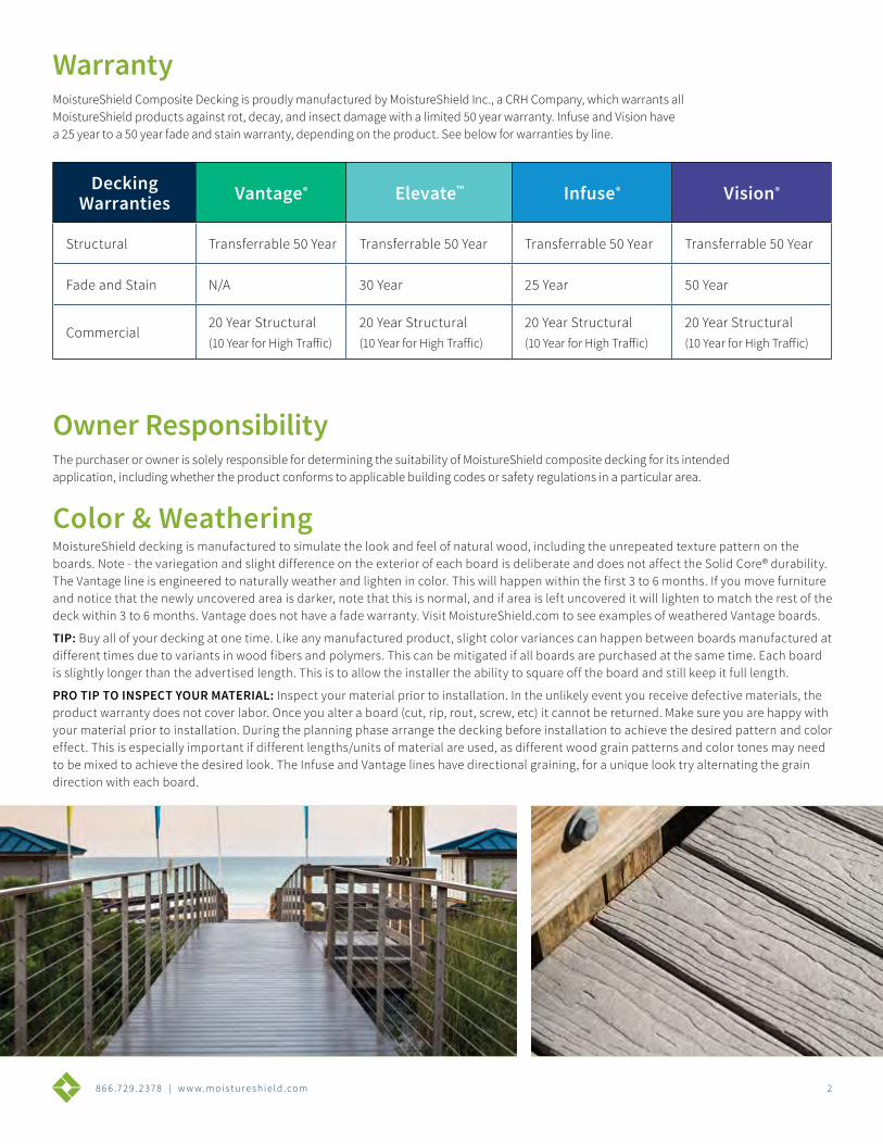
Color & WeatheringMoistureShield decking is manufactured to simulate the look and feel of natural wood, including the unrepeated texture pattern on the boards. Note - the variegation and slight difference on the exterior of each board is deliberate and does not affect the Solid Core® durability. The Vantage line is engineered to naturally weather and lighten in color. This will happen within the first 3 to 6 months. If you move furniture and notice that the newly uncovered area is darker, note that this is normal, and if area is left uncovered it will lighten to match the rest of the deck within 3 to 6 months. Vantage does not have a fade warranty. Visit MoistureShield.com to see examples of weathered Vantage boards.
TIP: Buy all of your decking at one time. Like any manufactured product, slight color variances can happen between boards manufactured at different times due to variants in wood fibers and polymers. This can be mitigated if all boards are purchased at the same time. Each board is slightly longer than the advertised length. This is to allow the installer the ability to square off the board and still keep it full length.
PRO TIP TO INSPECT YOUR MATERIAL: Inspect your material prior to installation. In the unlikely event you receive defective materials, the product warranty does not cover labor. Once you alter a board (cut, rip, rout, screw, etc) it cannot be returned. Make sure you are happy with your material prior to installation. During the planning phase arrange the decking before installation to achieve the desired pattern and color effect. This is especially important if different lengths/units of material are used, as different wood grain patterns and color tones may need to be mixed to achieve the desired look. The Infuse and Vantage lines have directional graining, for a unique look try alternating the grain direction with each board.
8 6 6 .7 2 9 . 2 3 7 8 | w w w. m o i s t u r e s h i e l d . c o m 3
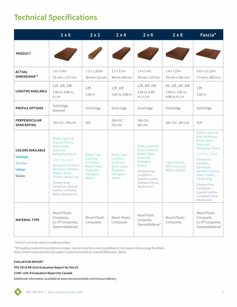
1 x 6 2 x 2 2 x 4 2 x 6 2 x 8 Fascia*
PRODUCT
ACTUAL DIMENSIONS**
1.0 x 5.4in
25 mm x 137 mm
1.5 x 1.265in
38 mm x 32 mm
1.5 x 3.5in
38 mm x 89 mm
1.4 x 5.4in
35 mm x 137 mm
1.4 x 7.25in
35 mm x 184 mm
0.67 x 11.25in
17 mm x 285 mm
LENGTHS AVAILABLE12ft, 16ft, 20ft
3.66 m, 4.88 m, 6.1 m
12ft
3.66 m
12ft, 16ft
3.66 m, 4.88 m
12ft, 16ft, 20ft
3.66 m, 4.88 m, 6.1 m
8ft, 12ft, 16ft, 20ft
2.44 m, 3.66 m, 4.88 m, 6.1 m
12ft
3.66 m
PROFILE OPTIONSSolid Edge, Grooved
Solid Edge Solid Edge Solid Edge Solid Edge Solid Edge
PERPENDICULAR SPAN RATING
16in O.C. (40 cm) N/A20in O.C. (50 cm)
24in O.C. (60 cm)
24in O.C. (60 cm) N/A
COLORS AVAILABLE
Vantage
Elevate
Infuse
Vision
Bridle, Cape Cod Gray, Earthtone, Rustic Cedar, Seasoned Mahogany, Walnut
Lake Fog, Canoe
Rosewood, Southern Barnwood, Northern Hickory, Rustic Timber, Harbor Gray
Smokey Gray, Sandstone, Spanish Leather, Cathedral Stone, Mochaccino
Bridle, Cape Cod Gray, Earthtone, Rustic Cedar, Seasoned Mahogany, Walnut
Bridle, Cape Cod Gray, Earthtone, Rustic Cedar, Seasoned Mahogany, Walnut
Bridle, Cape Cod Gray, Earthtone, Rustic Cedar, Seasoned Mahogany, Walnut
Smokey Gray, Sandstone, Spanish Leather, Cathedral Stone, Mochaccino
Cape Cod Gray. Other colors are MOQ truckload.
Bridle, Cape Cod Gray, Earthtone, Rustic Cedar, Seasoned Mahogany, Walnut
Lake Fog, Canoe
Rosewood, Southern Barnwood, Northern Hickory, Rustic Timber, Harbor Gray
Smokey Gray, Sandstone, Spanish Leather, Cathedral Stone, Mochaccino
MATERIAL TYPE
Wood-Plastic Composite, Co-X® Composite, DiamondDefense™
Wood-Plastic Composite
Wood-Plastic Composite
Wood-Plastic Composite, DiamondDefense™
Wood-Plastic Composite
Wood-Plastic Composite, Co-X® Composite, DiamondDefense™
Technical Specifications
* Fascia is not to be used as a walking surface.
**All building materials have tolerance ranges. See technical documents published on the resource library page for details. https://www.moistureshield.com/support-resources/contractor-rewards/#resource_library
EVALUATION REPORT:
PFS TECO RR-0110 Evaluation Report for the US
CCMC 1191-R Evaluation Report for Canada
Additional information available at www.moistureshield.com/resourcelibrary
8 6 6 .7 2 9 . 2 3 7 8 | w w w. m o i s t u r e s h i e l d . c o m 4
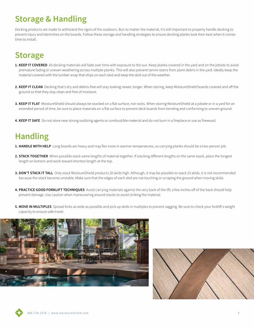
Decking products are made to withstand the rigors of the outdoors. But no matter the material, it’s still important to properly handle decking to prevent injury and blemishes on the boards. Follow these storage and handling strategies to ensure decking planks look their best when it comes time to install.
Storage1. KEEP IT COVERED All decking materials will fade over time with exposure to the sun. Keep planks covered in the yard and on the jobsite to avoid
premature fading or uneven weathering across multiple planks. This will also prevent tannin stains from plant debris in the yard. Ideally keep the material covered with the lumber wrap that ships on each skid and keep the skid out of the weather.
2. KEEP IT CLEAN Decking that’s dry and debris-free will stay looking newer, longer. When storing, keep MoistureShield boards covered and off the ground so that they stay clean and free of moisture.
3. KEEP IT FLAT MoistureShield should always be stacked on a flat surface, not racks. When storing MoistureShield at a jobsite or in a yard for an extended period of time, be sure to place materials on a flat surface to prevent deck boards from bending and conforming to uneven ground.
4. KEEP IT SAFE Do not store near strong oxidizing agents or combustible material and do not burn in a fireplace or use as firewood.
Handling1. HANDLE WITH HELP Long boards are heavy and may flex more in warmer temperatures, so carrying planks should be a two-person job. 2. STACK TOGETHER When possible stack same lengths of material together. If stacking different lengths on the same stack, place the longest
length on bottom and work toward shortest length at the top.
3. DON’T STACK IT TALL Only stack MoistureShield products 20 skids high. Although, it may be possible to stack 25 skids, it is not recommended because the stack become unstable. Make sure that the edges of each skid are not touching or scraping the ground when moving skids.
4. PRACTICE GOOD FORKLIFT TECHNIQUES Avoid carrying materials against the very back of the lift; a few inches off of the back should help prevent damage. Use caution when maneuvering around stacks to avoid striking the material.
5. MOVE IN MULTIPLES Spread forks as wide as possible and pick up skids in multiples to prevent sagging. Be sure to check your forklift’s weight capacity to ensure safe travel.
Storage & Handling
8 6 6 .7 2 9 . 2 3 7 8 | w w w. m o i s t u r e s h i e l d . c o m 5
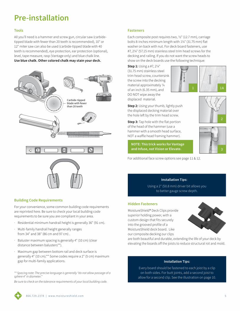
Tools
All you’ll need is a hammer and screw gun, circular saw (carbide-tipped blade with fewer than 20 teeth is recommended), 10" or 12" miter saw can also be used (carbide-tipped blade with 40 teeth is recommended), eye protection, ear protection (optional), level, tape measure, rasp (Vantage only) and blue chalk line. Use blue chalk. Other colored chalk may stain your deck.
Fasteners
Each composite post requires two, 1/2" (12.7 mm), carriage bolts 8-inches minimum length with 11/4" (31.75 mm) flat washer on back with nut. For deck board fasteners, use #7, 21/4" (57.15 mm) stainless steel trim head screws for the decking and railing. If you do not want the screw heads to show on the deck boards use the following technique:
Hidden Fasteners
MoistureShield® Deck Clips provide superior holding power, with a custom design that fits securely into the grooved profile of a MoistureShield deck board. Like our composite decking our clips are both beautiful and durable, extending the life of your deck by elevating the boards off the joists to reduce structural rot and mold.
Installation Tips:
Using a 2" (50.8 mm) driver bit allows you to better gauge screw depth.
Installation Tips:
Every board should be fastened to each joist by a clip on both sides. For butt joints, add a second joist to
allow for a second clip. See the illustration on page 10.
Step 1: Using a #7, 21/4" (31.75 mm) stainless steel trim head screw, countersink the screw into the decking material approximately 1/4 of an inch (6.35 mm), and DO NOT wipe away the displaced material.
Step 2: Using your thumb, lightly push the displaced decking material over the hole left by the trim head screw.
Step 3: Tap hole with the flat portion of the head of the hammer (use a hammer with a smooth head surface, NOT a waffle head framing hammer).
NOTE: This trick works for Vantage and Infuse, not Vision or Elevate.
Carbide-tipped blade with fewer than 20 teeth.Carbide-tipped blade with fewer than 20 teeth.
Carbide-tipped blade with fewer than 20 teeth.
Carbide-tipped blade with fewer than 20 teeth.
Building Code Requirements
For your convenience, some common building code requirements are reprinted here. Be sure to check your local building code requirements to be sure you are compliant in your area.
· Residential minimum handrail height is generally 36" (91 cm).
· Multi-family handrail height generally ranges from 34" and 38" (86 cm and 97 cm) .
· Baluster maximum spacing is generally 4" (10 cm) (clear distance between balusters**).
· Maximum gap between bottom rail and deck surface is generally 4" (10 cm).** Some codes require a 2" (5 cm) maximum gap for multi-family applications.
** Spacing note: The precise language is generally “do not allow passage of a sphere 4" in diameter.”
Be sure to check on the tolerance requirements of your local building code.
1 1A
2
3
Pre-installation
Carbide-tipped blade with fewer than 20 teeth
For additional face screw options see page 11 & 12.
8 6 6 .7 2 9 . 2 3 7 8 | w w w. m o i s t u r e s h i e l d . c o m 6
Complete systemCovers 50 square feet of decking
• 5 starter clips
• 5 finish clips
• 90 clips
• 90 screws or 90 pneumatic fasteners
Deck/Contractor packCovers 250 square feet of decking
• 450 clips
• 500 screws (Deck Pack) or 500 pneumatic fasteners (Contractor Pack)
*Does not include starter or finish clips
*All clips available in stainless steel
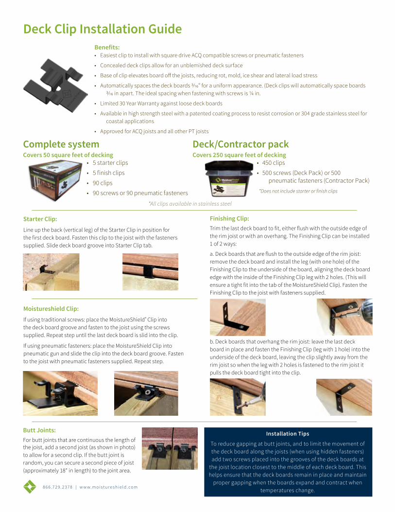
Deck Clip Installation GuideBenefits:• Easiest clip to install with square drive ACQ compatible screws or pneumatic fasteners
• Concealed deck clips allow for an unblemished deck surface
• Base of clip elevates board off the joists, reducing rot, mold, ice shear and lateral load stress
• Automatically spaces the deck boards 3/16” for a uniform appearance. (Deck clips will automatically space boards 3/16 in apart. The ideal spacing when fastening with screws is 1/4 in.
• Limited 30 Year Warranty against loose deck boards
• Available in high strength steel with a patented coating process to resist corrosion or 304 grade stainless steel for coastal applications
• Approved for ACQ joists and all other PT joists
Starter Clip:
Line up the back (vertical leg) of the Starter Clip in position for the first deck board. Fasten this clip to the joist with the fasteners supplied. Slide deck board groove into Starter Clip tab.
Finishing Clip:Trim the last deck board to fit, either flush with the outside edge of the rim joist or with an overhang. The Finishing Clip can be installed 1 of 2 ways:
a. Deck boards that are flush to the outside edge of the rim joist: remove the deck board and install the leg (with one hole) of the Finishing Clip to the underside of the board, aligning the deck board edge with the inside of the Finishing Clip leg with 2 holes. (This will ensure a tight fit into the tab of the MoistureShield Clip). Fasten the Finishing Clip to the joist with fasteners supplied.
Butt Joints:For butt joints that are continuous the length of the joist, add a second joist (as shown in photo) to allow for a second clip. If the butt joint is random, you can secure a second piece of joist (approximately 18" in length) to the joint area.
b. Deck boards that overhang the rim joist: leave the last deck board in place and fasten the Finishing Clip (leg with 1 hole) into the underside of the deck board, leaving the clip slightly away from the rim joist so when the leg with 2 holes is fastened to the rim joist it pulls the deck board tight into the clip.
Moistureshield Clip:
If using traditional screws: place the MoistureShield® Clip into the deck board groove and fasten to the joist using the screws supplied. Repeat step until the last deck board is slid into the clip.
If using pneumatic fasteners: place the MoistureShield Clip into pneumatic gun and slide the clip into the deck board groove. Fasten to the joist with pneumatic fasteners supplied. Repeat step.
Installation Tips
To reduce gapping at butt joints, and to limit the movement of the deck board along the joists (when using hidden fasteners) add two screws placed into the grooves of the deck boards at
the joist location closest to the middle of each deck board. This helps ensure that the deck boards remain in place and maintain
proper gapping when the boards expand and contract when temperatures change.
8 6 6 .7 2 9 . 2 3 7 8 | w w w. m o i s t u r e s h i e l d . c o m 7
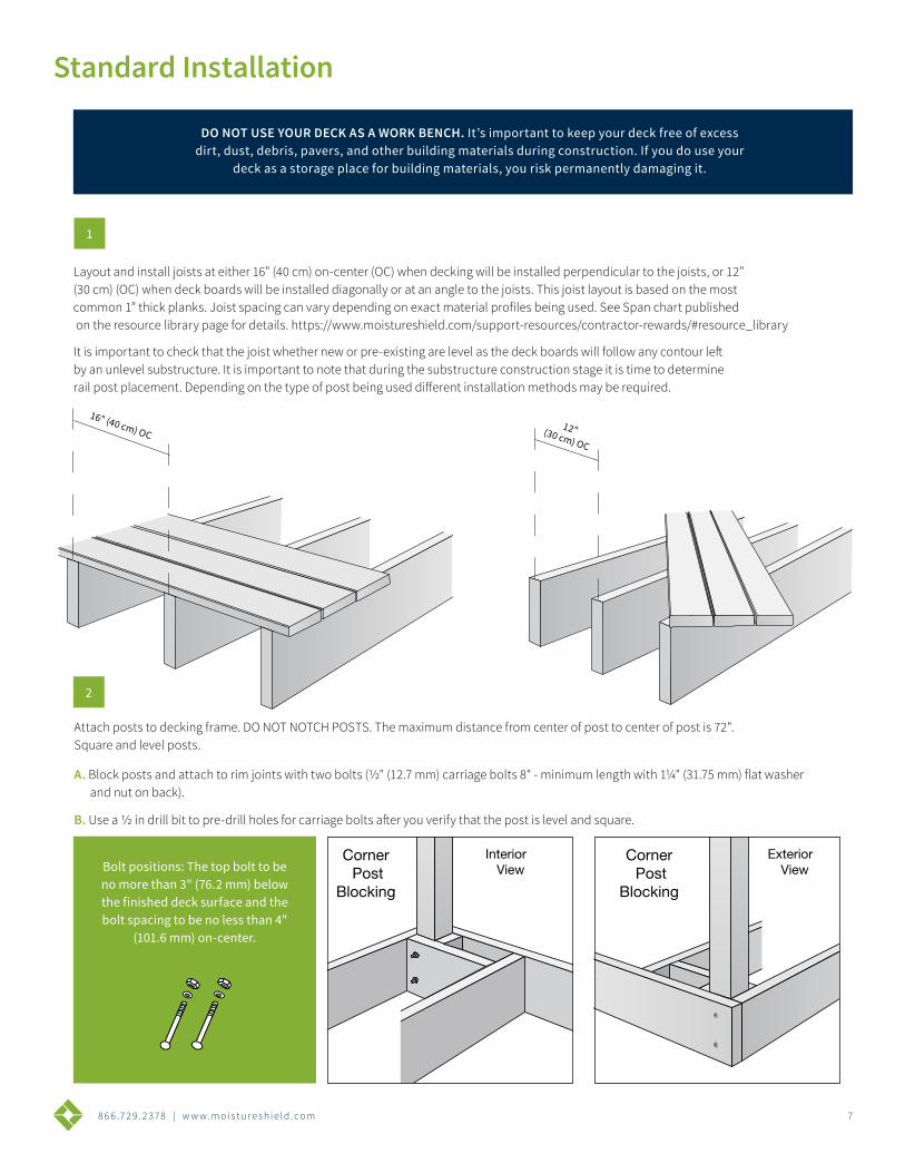
Attach posts to decking frame. DO NOT NOTCH POSTS. The maximum distance from center of post to center of post is 72". Square and level posts.
A. Block posts and attach to rim joints with two bolts (1/2" (12.7 mm) carriage bolts 8" - minimum length with 11/4" (31.75 mm) flat washer and nut on back).
B. Use a 1/2 in drill bit to pre-drill holes for carriage bolts after you verify that the post is level and square.
1
DO NOT USE YOUR DECK AS A WORK BENCH. It’s important to keep your deck free of excess dirt, dust, debris, pavers, and other building materials during construction. If you do use your
deck as a storage place for building materials, you risk permanently damaging it.
2
Bolt positions: The top bolt to be no more than 3" (76.2 mm) below the finished deck surface and the bolt spacing to be no less than 4"
(101.6 mm) on-center.
Corner Post
Blocking
Line PostBlocking
InteriorView
InteriorView
ExteriorView
ExteriorView
Line PostBlocking
Corner Post
Blocking
Corner Post
Blocking
Line PostBlocking
InteriorView
InteriorView
ExteriorView
ExteriorView
Line PostBlocking
Corner Post
Blocking
Standard Installation
16" (40 cm) OC12" (30 cm) OC
Layout and install joists at either 16” (40 cm) on-center (OC) when decking will be installed perpendicular to the joists, or 12” (30 cm) (OC) when deck boards will be installed diagonally or at an angle to the joists. This joist layout is based on the most common 1” thick planks. Joist spacing can vary depending on exact material profiles being used. See Span chart published on the resource library page for details. https://www.moistureshield.com/support-resources/contractor-rewards/#resource_library
It is important to check that the joist whether new or pre-existing are level as the deck boards will follow any contour left by an unlevel substructure. It is important to note that during the substructure construction stage it is time to determine rail post placement. Depending on the type of post being used different installation methods may be required.
866 .729 . 2 378 | www.mois tu re sh ie ld . com 1
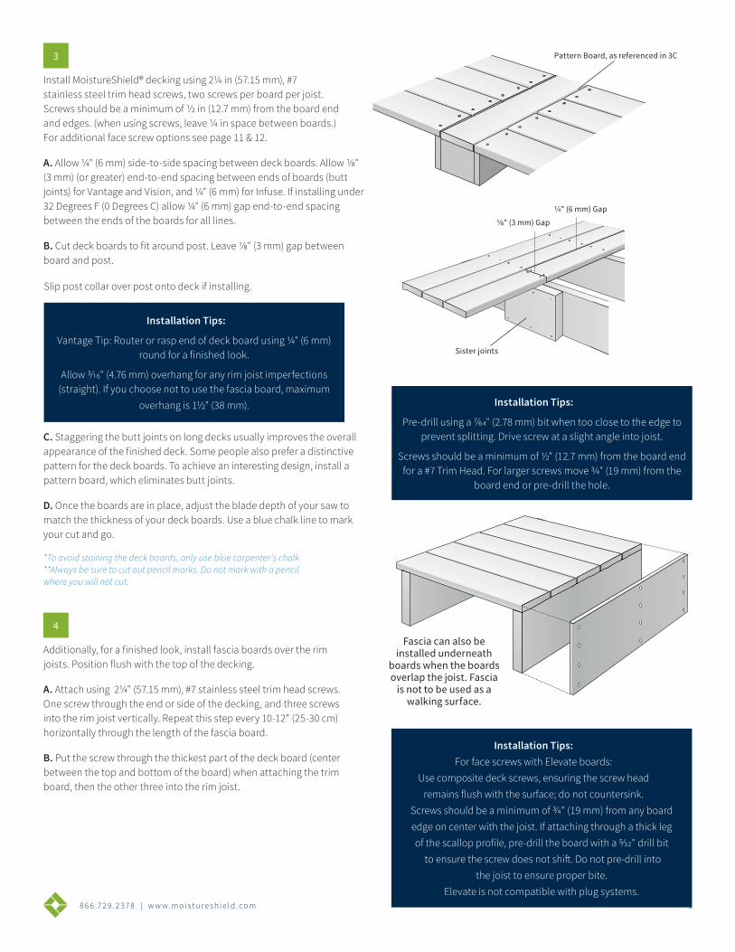
Install MoistureShield® decking using 21/4 in (57.15 mm), #7 stainless steel trim head screws, two screws per board per joist. Screws should be a minimum of 1/2 in (12.7 mm) from the board end and edges. (when using screws, leave 1/4 in space between boards.) For additional face screw options see page 11 & 12.
A. Allow ¼" (6 mm) side-to-side spacing between deck boards. Allow 1/8" (3 mm) (or greater) end-to-end spacing between ends of boards (butt joints) for Vantage and Vision, and ¼" (6 mm) for Infuse. If installing under 32 Degrees F (0 Degrees C) allow ¼" (6 mm) gap end-to-end spacing between the ends of the boards for all lines.
B. Cut deck boards to fit around post. Leave 1/8" (3 mm) gap between board and post.
C. Staggering the butt joints on long decks usually improves the overall appearance of the finished deck. Some people also prefer a distinctive pattern for the deck boards. To achieve an interesting design, install a pattern board, which eliminates butt joints.
D. Once the boards are in place, adjust the blade depth of your saw to match the thickness of your deck boards. Use a blue chalk line to mark your cut and go.
*To avoid staining the deck boards, only use blue carpenter’s chalk. **Always be sure to cut out pencil marks. Do not mark with a pencil where you will not cut.
3
Additionally, for a finished look, install fascia boards over the rim joists. Position flush with the top of the decking.
A. Attach using 21/4" (57.15 mm), #7 stainless steel trim head screws. One screw through the end or side of the decking, and three screws into the rim joist vertically. Repeat this step every 10-12" (25-30 cm) horizontally through the length of the fascia board.
B. Put the screw through the thickest part of the deck board (center between the top and bottom of the board) when attaching the trim board, then the other three into the rim joist.
4
1/4” Gap
1/8” Gap
Fascia can also be installed underneath
boards when the boards overlap the joist. Fascia is not to be used as a walking surface.
Pattern Board, as referenced in 3C
Sister joints
Slip post collar over post onto deck if installing.
Installation Tips:
Vantage Tip: Router or rasp end of deck board using ¼" (6 mm) round for a finished look.
Allow 3/16" (4.76 mm) overhang for any rim joist imperfections (straight). If you choose not to use the fascia board, maximum
overhang is 11/2" (38 mm). Installation Tips:
Pre-drill using a 7/64" (2.78 mm) bit when too close to the edge to prevent splitting. Drive screw at a slight angle into joist.
Screws should be a minimum of ½" (12.7 mm) from the board end for a #7 Trim Head. For larger screws move 3/4" (19 mm) from the
board end or pre-drill the hole.
1/4" (6 mm) Gap
1/8" (3 mm) Gap
Installation Tips:For face screws with Elevate boards:
Use composite deck screws, ensuring the screw head remains flush with the surface; do not countersink.
Screws should be a minimum of 3/4" (19 mm) from any board edge on center with the joist. If attaching through a thick leg of the scallop profile, pre-drill the board with a 5/32" drill bit to ensure the screw does not shift. Do not pre-drill into
the joist to ensure proper bite.Elevate is not compatible with plug systems.
98 6 6 .7 2 9 . 2 3 7 8 | w w w. m o i s t u r e s h i e l d . c o m
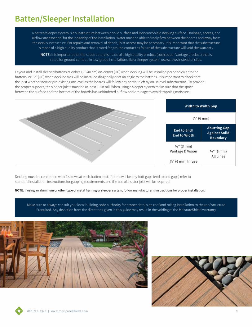
Layout and install sleeper/battens at either 16" (40 cm) on-center (OC) when decking will be installed perpendicular to the battens, or 12" (OC) when deck boards will be installed diagonally or at an angle to the battens. It is important to check that the joist whether new or pre-existing are level as the boards will follow any contour left by an unlevel substructure. To provide the proper supoort, the sleeper joists must be at least 1.5in tall. When using a sleeper system make sure that the space between the surface and the bottom of the boards has unhindered airflow and drainage to avoid trapping moisture.
Decking must be connected with 2 screws at each batten joist. If there will be any butt gaps (end to end gaps) refer to standard installation instructions for gapping requirements and the use of a sister joist will be required.
NOTE: If using an aluminum or other type of metal framing or sleeper system, follow manufacturer's instructions for proper installation.
Width to Width Gap
1/4" (6 mm)
End to End/ End to Width
Abutting Gap Against Solid
Boundary
1/8" (3 mm) Vantage & Vision
1/4" (6 mm) Infuse
1/4" (6 mm) All Lines
Batten/Sleeper InstallationA batten/sleeper system is a substructure between a solid surface and MoistureShield decking surface. Drainage, access, and airflow are essential for the longevity of the installation. Water must be able to freely flow between the boards and away from the deck substructure. For repairs and removal of debris, joist access may be necessary. It is important that the substructure
is made of a high quality product that is rated for ground contact as failure of the substructure will void the warranty.
NOTE: It is important that the substructure is made of a high quality product (such as our Vantage product) that is rated for ground contact. In low-grade installations like a sleeper system, use screws instead of clips.
Make sure to always consult your local building code authority for proper details on roof and railing installation to the roof structure if required. Any deviation from the directions given in this guide may result in the voiding of the MoistureShield warranty.
8 6 6 .7 2 9 . 2 3 7 8 | w w w. m o i s t u r e s h i e l d . c o m 10
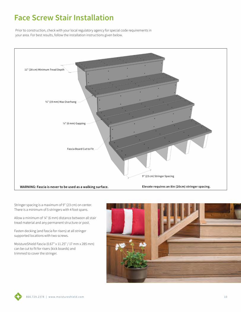
Prior to construction, check with your local regulatory agency for special code requirements in your area. For best results, follow the installation instructions given below.
Stringer spacing is a maximum of 9" (23 cm) on center. There is a minimum of 5 stringers with 4 foot spans.
Allow a minimum of 1/4" (6 mm) distance between all stair tread material and any permanent structure or post.
Fasten decking (and fascia for risers) at all stringer supported locations with two screws.
MoistureShield Fascia (0.67" x 11.25" / 17 mm x 285 mm) can be cut to fit for risers (kick boards) and trimmed to cover the stringer.
WARNING: Fascia is never to be used as a walking surface.
Face Screw Stair Installation
11" (28 cm) Minimum Tread Depth
3/4" (19 mm) Max Overhang
1/4" (6 mm) Gapping
Fascia Board Cut to Fit
9" (23 cm) Stringer Spacing
Elevate requires an 8in (20cm) stringer spacing.
8 6 6 .7 2 9 . 2 3 7 8 | w w w. m o i s t u r e s h i e l d . c o m 1 1
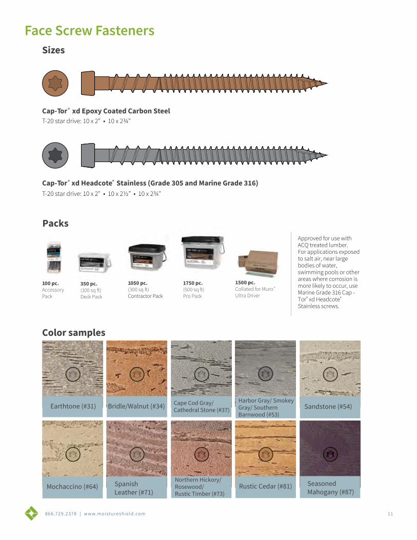
Packs
Cap-Tor® xd Epoxy Coated Carbon Steel
Harbor Gray/ SmokeyGray/ Southern Barnwood (#53)
Sizes
100 pc. AccessoryPack
350 pc. (100 sq ft) Deck Pack
1050 pc. (300 sq ft)Contractor Pack
1750 pc. (500 sq ft)Pro Pack
1500 pc.Collated for Muro ® Ultra Driver
Color samples
Cap-Tor® xd Headcote® Stainless (Grade 305 and Marine Grade 316)
Earthtone (#31)
Northern Hickory/Rosewood/Rustic Timber (#73)
Bridle/Walnut (#34) Sandstone (#54)
Rustic Cedar (#81)
Cape Cod Gray/Cathedral Stone (#37)
Seasoned Mahogany (#87)
Mochaccino (#64) SpanishLeather (#71)
T-20 star drive: 10 x 2" • 10 x 2¾"
T-20 star drive: 10 x 2" • 10 x 2½” • 10 x 2¾"
Approved for use with ACQ treated lumber. For applications exposed to salt air, near large bodies of water, swimming pools or other areas where corrosion is more likely to occur, use Marine Grade 316 Cap - Tor® xd Headcote® Stainless screws.
Face Screw Fasteners
8 6 6 .7 2 9 . 2 3 7 8 | w w w. m o i s t u r e s h i e l d . c o m 1 2
8 6 6 .7 2 9 . 2 3 7 8 | w w w. m o i s t u r e s h i e l d . c o m 1 3
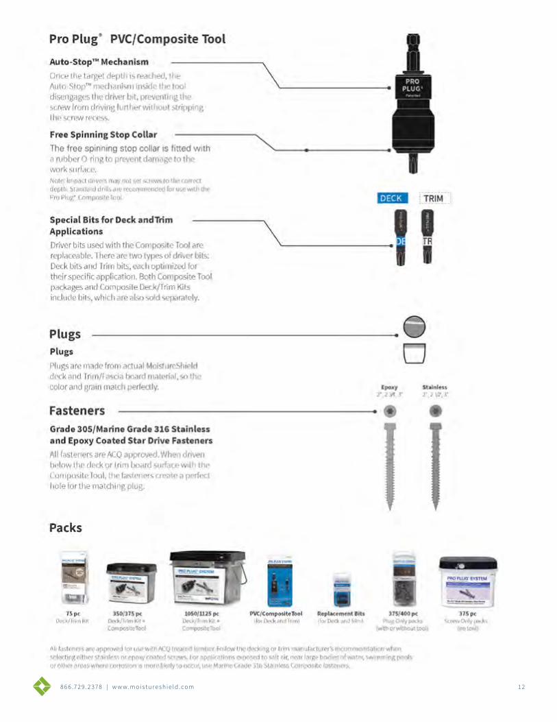
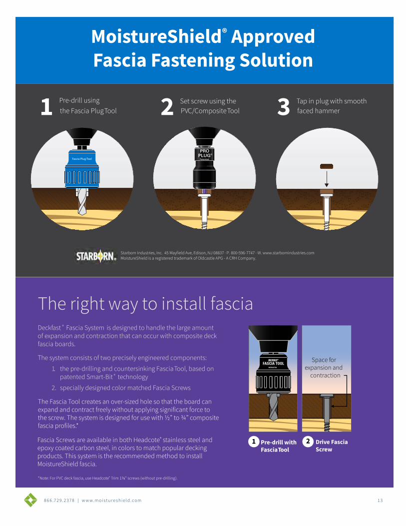
Deckfast ® Fascia System is designed to handle the large amount of expansion and contraction that can occur with composite deck fascia boards.
The system consists of two precisely engineered components:
1. the pre-drilling and countersinking Fascia Tool, based on patented Smart-Bit ® technology
2. specially designed color matched Fascia Screws
The right way to install fascia
Space for expansion and
contractionPATENTED
1 Pre-drill with Fascia Tool
2 Drive Fascia Screw
The Fascia Tool creates an over-sized hole so that the board canexpand and contract freely without applying significant force tothe screw. The system is designed for use with ½” to ¾” compositefascia profiles.*
Fascia Screws are available in both Headcote® stainless steel and epoxy coated carbon steel, in colors to match popular decking products. This system is the recommended method to install MoistureShield fascia.
*Note: For PVC deck fascia, use Headcote® Trim 1⅝” screws (without pre-drilling).
Starborn Industries, Inc. 45 Mayfield Ave, Edison, NJ 08837 · P. 800-596-7747 · W. www.starbornindustries.comMoistureShield is a registered trademark of Oldcastle APG - A CRH Company.
MoistureShield® Approved Fascia Fastening Solution
Fascia Plug Tool Patented
1 Pre-drill using the Fascia Plug Tool 2 Set screw using the
PVC/Composite Tool 3 Tap in plug with smooth faced hammer
8 6 6 .7 2 9 . 2 3 7 8 | w w w. m o i s t u r e s h i e l d . c o m 14
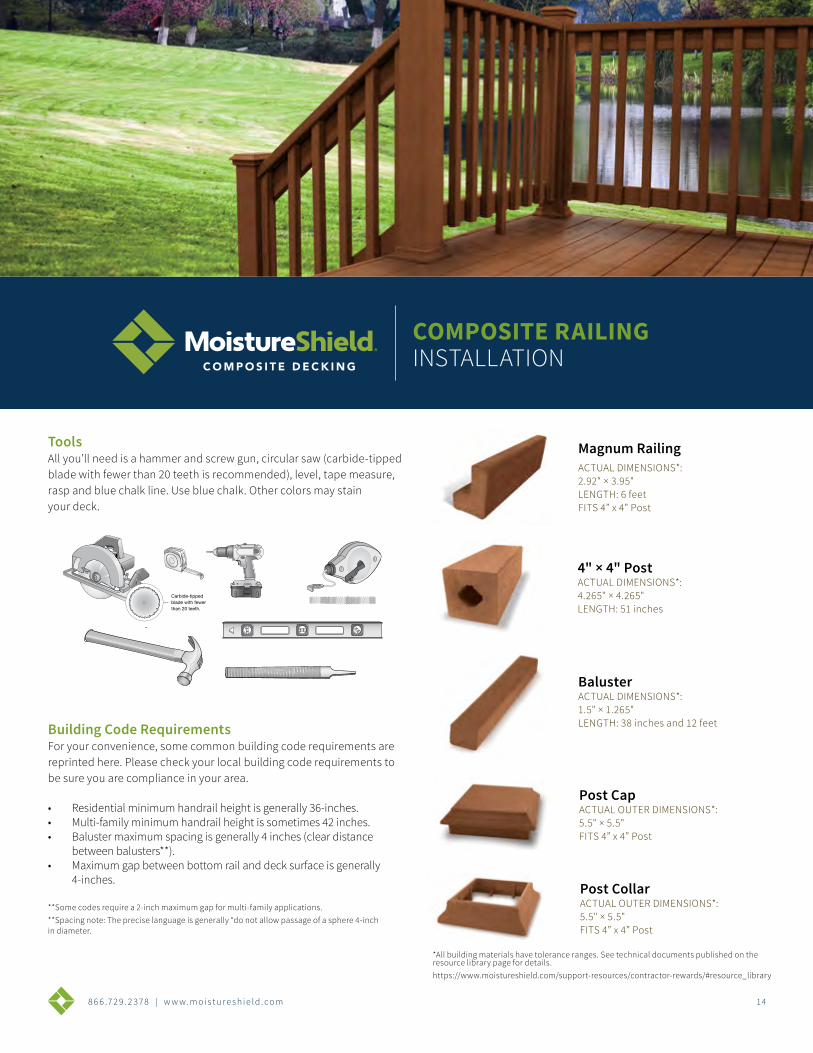
ToolsAll you’ll need is a hammer and screw gun, circular saw (carbide-tipped blade with fewer than 20 teeth is recommended), level, tape measure, rasp and blue chalk line. Use blue chalk. Other colors may stain your deck.
Building Code RequirementsFor your convenience, some common building code requirements are reprinted here. Please check your local building code requirements to be sure you are compliance in your area.
• Residential minimum handrail height is generally 36-inches.• Multi-family minimum handrail height is sometimes 42 inches.• Baluster maximum spacing is generally 4 inches (clear distance
between balusters**).• Maximum gap between bottom rail and deck surface is generally
4-inches.
**Some codes require a 2-inch maximum gap for multi-family applications.**Spacing note: The precise language is generally “do not allow passage of a sphere 4-inch in diameter.
Carbide-tipped blade with fewer than 20 teeth.
Carbide-tipped blade with fewer than 20 teeth.
Carbide-tipped blade with fewer than 20 teeth.
Carbide-tipped blade with fewer than 20 teeth.
COMPOSITE RAILINGINSTALLATION
BalusterACTUAL DIMENSIONS*:1.5" × 1.265"LENGTH: 38 inches and 12 feet
Magnum RailingACTUAL DIMENSIONS*:2.92" × 3.95"LENGTH: 6 feetFITS 4” x 4” Post
Post CapACTUAL OUTER DIMENSIONS*:5.5" × 5.5"FITS 4” x 4” Post
Post CollarACTUAL OUTER DIMENSIONS*:5.5" × 5.5"FITS 4” x 4” Post
4" × 4" PostACTUAL DIMENSIONS*:4.265" × 4.265"LENGTH: 51 inches
*All building materials have tolerance ranges. See technical documents published on the resource library page for details.https://www.moistureshield.com/support-resources/contractor-rewards/#resource_library
8 6 6 .7 2 9 . 2 3 7 8 | w w w. m o i s t u r e s h i e l d . c o m 1 5
COMPOSITE RAILING INSTALLATION
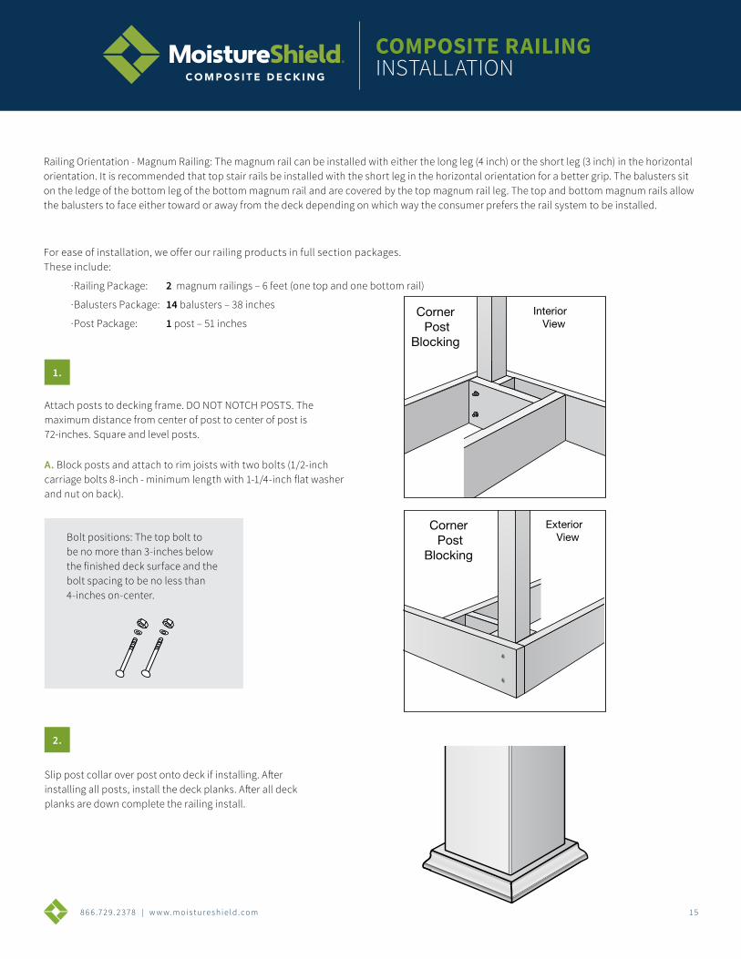
Attach posts to decking frame. DO NOT NOTCH POSTS. The maximum distance from center of post to center of post is 72-inches. Square and level posts.
A. Block posts and attach to rim joists with two bolts (1/2-inch carriage bolts 8-inch - minimum length with 1-1/4-inch flat washer and nut on back).
1.
2.
Bolt positions: The top bolt to be no more than 3-inches below the finished deck surface and the bolt spacing to be no less than 4-inches on-center.
Corner Post
Blocking
Line PostBlocking
InteriorView
InteriorView
ExteriorView
ExteriorView
Line PostBlocking
Corner Post
Blocking
Corner Post
Blocking
Line PostBlocking
InteriorView
InteriorView
ExteriorView
ExteriorView
Line PostBlocking
Corner Post
Blocking
Railing Orientation - Magnum Railing: The magnum rail can be installed with either the long leg (4 inch) or the short leg (3 inch) in the horizontal orientation. It is recommended that top stair rails be installed with the short leg in the horizontal orientation for a better grip. The balusters sit on the ledge of the bottom leg of the bottom magnum rail and are covered by the top magnum rail leg. The top and bottom magnum rails allow the balusters to face either toward or away from the deck depending on which way the consumer prefers the rail system to be installed.
For ease of installation, we offer our railing products in full section packages. These include:
· Railing Package: 2 magnum railings – 6 feet (one top and one bottom rail)
· Balusters Package: 14 balusters – 38 inches
· Post Package: 1 post – 51 inches
Slip post collar over post onto deck if installing. After installing all posts, install the deck planks. After all deck planks are down complete the railing install.
8 6 6 .7 2 9 . 2 3 7 8 | w w w. m o i s t u r e s h i e l d . c o m 16
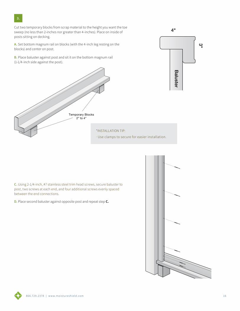
*INSTALLATION TIP:
· Use clamps to secure for easier installation.
Temporary Blocks
Cut two temporary blocks from scrap material to the height you want the toe sweep (no less than 2-inches nor greater than 4-inches). Place on inside of posts sitting on decking.
A. Set bottom magnum rail on blocks (with the 4-inch leg resting on the blocks) and center on post.
B. Place baluster against post and sit it on the bottom magnum rail (1-1/4-inch side against the post).
C. Using 2-1/4-inch, #7 stainless steel trim head screws, secure baluster to post, two screws at each end, and four additional screws evenly spaced between the end connections.
D. Place second baluster against opposite post and repeat step C.
3.
Baluster
1-1/4"
4"
3"
8 6 6 .7 2 9 . 2 3 7 8 | w w w. m o i s t u r e s h i e l d . c o m 17
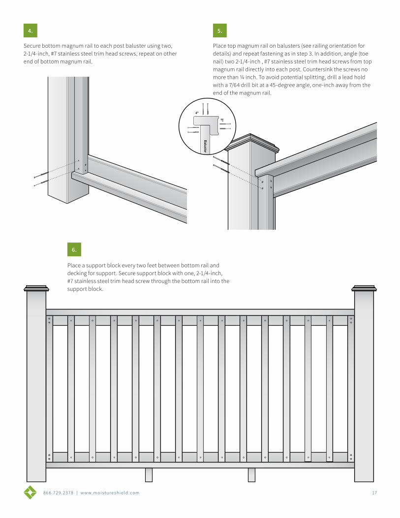
Secure bottom magnum rail to each post baluster using two, 2-1/4-inch, #7 stainless steel trim head screws, repeat on other end of bottom magnum rail.
Place a support block every two feet between bottom rail and decking for support. Secure support block with one, 2-1/4-inch, #7 stainless steel trim head screw through the bottom rail into the support block.
Place top magnum rail on balusters (see railing orientation for details) and repeat fastening as in step 3. In addition, angle (toe nail) two 2-1/4-inch , #7 stainless steel trim head screws from top magnum rail directly into each post. Countersink the screws no more than ¼ inch. To avoid potential splitting, drill a lead hold with a 7/64 drill bit at a 45-degree angle, one-inch away from the end of the magnum rail.
4. 5.
6.
Baluster
1-1/4"
4"
3"
8 6 6 .7 2 9 . 2 3 7 8 | w w w. m o i s t u r e s h i e l d . c o m 1 8
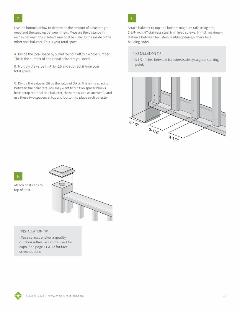
Use the formula below to determine the amount of balusters you need and the spacing between them. Measure the distance in inches between the inside of one post baluster to the inside of the other post baluster. This is your total space.
A. Divide the total space by 5, and round it off to a whole number. This is the number of additional balusters you need.
B. Multiply the value in (A) by 1.5 and subtract it from your total space.
C. Divide the value in (B) by the value of (A+1). This is the spacing between the balusters. You may want to cut two spacer blocks from scrap material or a baluster, the same width as answer C, and use these two spacers at top and bottom to place each baluster.
Attach post caps to top of post.
Attach baluster to top and bottom magnum rails using one, 2-1/4-inch, #7 stainless steel trim head screws. (4-inch maximum distance between balusters, visible opening – check local building code).
7.
9.
8.
*INSTALLATION TIP:
· 3-1/2-inches between balusters is always a good starting point.
*INSTALLATION TIP:
· Face screws and/or a quality outdoor adhesive can be used for caps. See page 11 & 12 for face screw options.
8 6 6 .7 2 9 . 2 3 7 8 | w w w. m o i s t u r e s h i e l d . c o m 1 9
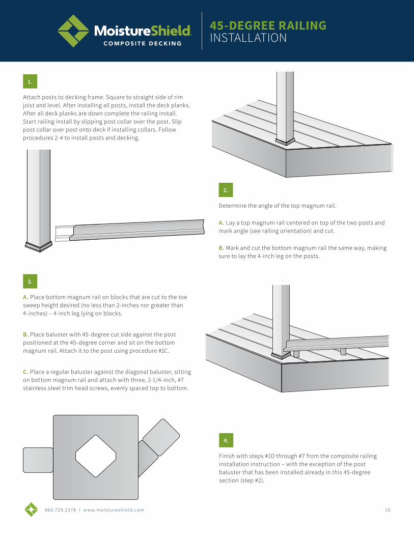
Attach posts to decking frame. Square to straight side of rim joist and level. After installing all posts, install the deck planks. After all deck planks are down complete the railing install. Start railing install by slipping post collar over the post. Slip post collar over post onto deck if installing collars. Follow procedures 2-4 to install posts and decking.
Determine the angle of the top magnum rail.
A. Lay a top magnum rail centered on top of the two posts and mark angle (see railing orientation) and cut.
B. Mark and cut the bottom magnum rail the same way, making sure to lay the 4-inch leg on the posts.
A. Place bottom magnum rail on blocks that are cut to the toe sweep height desired (no less than 2-inches nor greater than 4-inches) – 4-inch leg lying on blocks.
B. Place baluster with 45-degree cut side against the post positioned at the 45-degree corner and sit on the bottom magnum rail. Attach it to the post using procedure #1C.
C. Place a regular baluster against the diagonal baluster, sitting on bottom magnum rail and attach with three, 2-1/4-inch, #7 stainless steel trim head screws, evenly spaced top to bottom.
Finish with steps #1D through #7 from the composite railing installation instruction – with the exception of the post baluster that has been installed already in this 45-degree section (step #2).
1.
2.
3.
4.
45-DEGREE RAILING INSTALLATION
8 6 6 .7 2 9 . 2 3 7 8 | w w w. m o i s t u r e s h i e l d . c o m 2 0
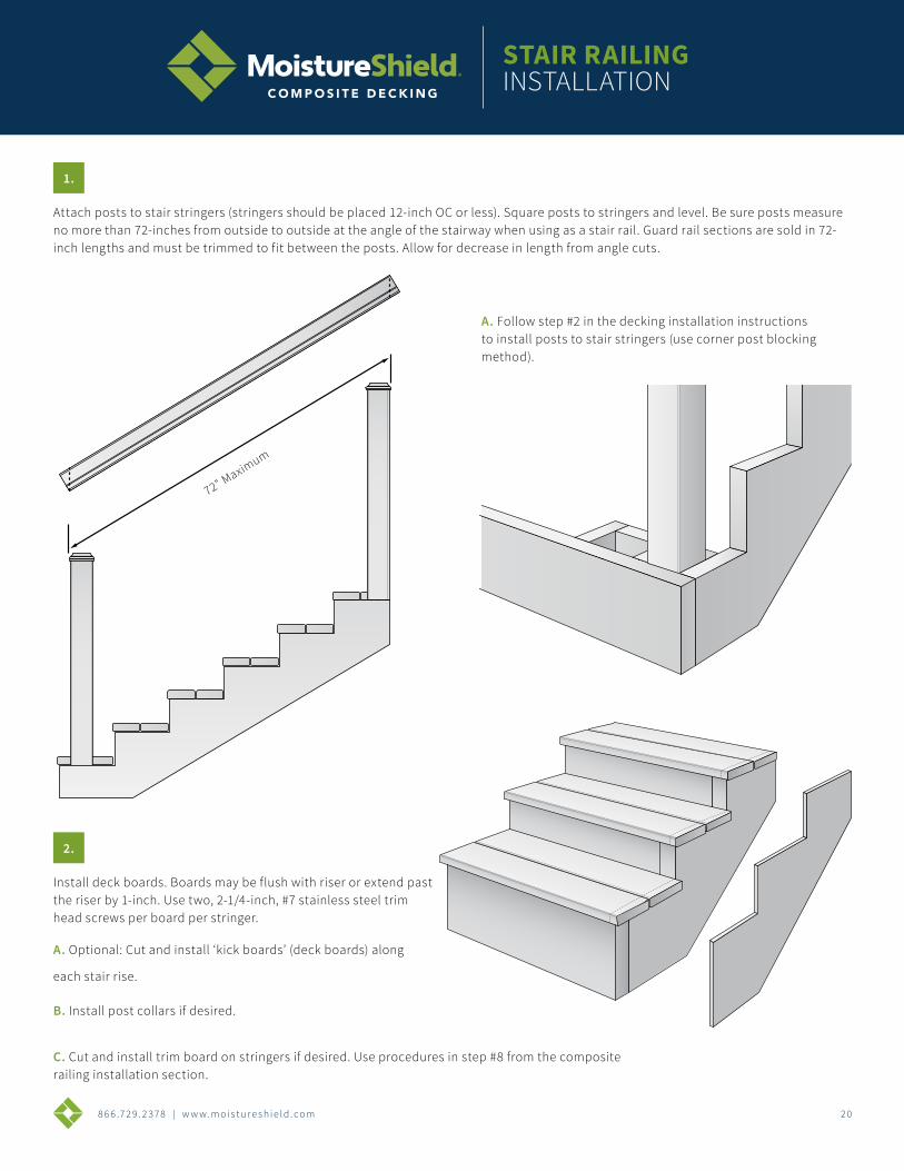
Attach posts to stair stringers (stringers should be placed 12-inch OC or less). Square posts to stringers and level. Be sure posts measure no more than 72-inches from outside to outside at the angle of the stairway when using as a stair rail. Guard rail sections are sold in 72-inch lengths and must be trimmed to fit between the posts. Allow for decrease in length from angle cuts.
72" Maximum
A. Follow step #2 in the decking installation instructions to install posts to stair stringers (use corner post blocking method).
Install deck boards. Boards may be flush with riser or extend past the riser by 1-inch. Use two, 2-1/4-inch, #7 stainless steel trim head screws per board per stringer.
A. Optional: Cut and install ‘kick boards’ (deck boards) along
each stair rise.
B. Install post collars if desired.
C. Cut and install trim board on stringers if desired. Use procedures in step #8 from the composite railing installation section.
1.
2.
STAIR RAILING INSTALLATION
8 6 6 .7 2 9 . 2 3 7 8 | w w w. m o i s t u r e s h i e l d . c o m 2 1
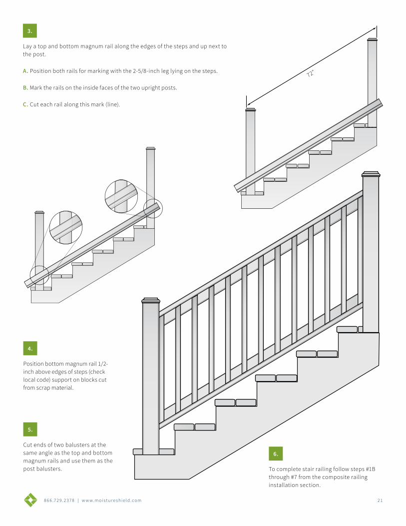
Lay a top and bottom magnum rail along the edges of the steps and up next to the post.
A. Position both rails for marking with the 2-5/8-inch leg lying on the steps.
B. Mark the rails on the inside faces of the two upright posts.
C. Cut each rail along this mark (line).
Position bottom magnum rail 1/2-inch above edges of steps (check local code) support on blocks cut from scrap material.
Cut ends of two balusters at the same angle as the top and bottom magnum rails and use them as the post balusters. To complete stair railing follow steps #1B
through #7 from the composite railing installation section.
3.
4.
5.
6.
72"
8 6 6 .7 2 9 . 2 3 7 8 | w w w. m o i s t u r e s h i e l d . c o m 2 2
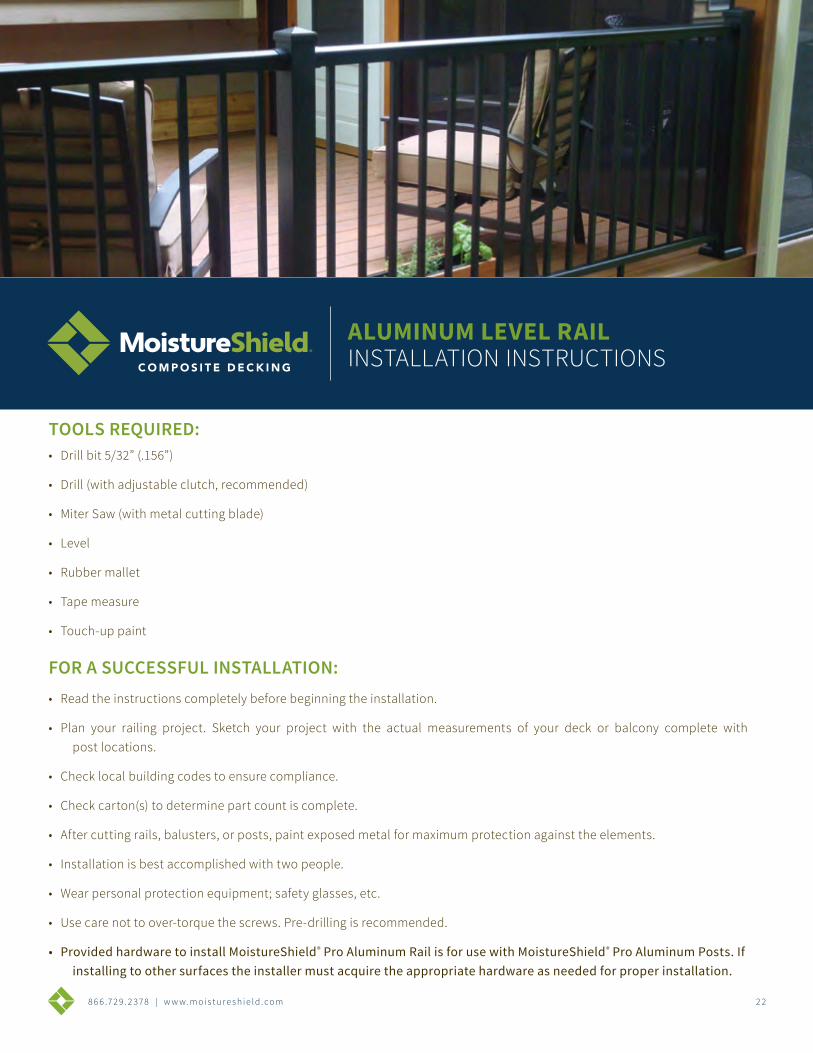
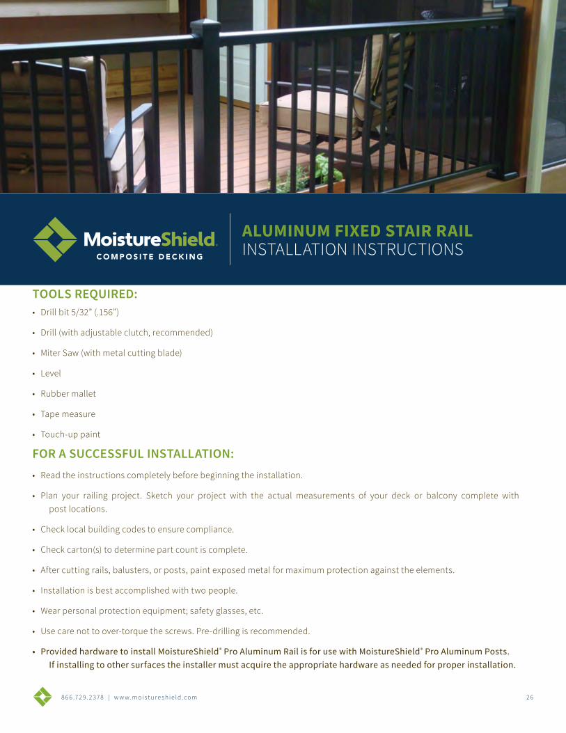
TOOLS REQUIRED:• Drill bit 5/32” (.156”)
• Drill (with adjustable clutch, recommended)
• Miter Saw (with metal cutting blade)
• Level
• Rubber mallet
• Tape measure
• Touch-up paint
ALUMINUM LEVEL RAILINSTALLATION INSTRUCTIONS
FOR A SUCCESSFUL INSTALLATION:• Read the instructions completely before beginning the installation.
• Plan your railing project. Sketch your project with the actual measurements of your deck or balcony complete with post locations.
• Check local building codes to ensure compliance.
• Check carton(s) to determine part count is complete.
• After cutting rails, balusters, or posts, paint exposed metal for maximum protection against the elements.
• Installation is best accomplished with two people.
• Wear personal protection equipment; safety glasses, etc.
• Use care not to over-torque the screws. Pre-drilling is recommended.
• Provided hardware to install MoistureShield® Pro Aluminum Rail is for use with MoistureShield® Pro Aluminum Posts. If installing to other surfaces the installer must acquire the appropriate hardware as needed for proper installation.
8 6 6 .7 2 9 . 2 3 7 8 | w w w. m o i s t u r e s h i e l d . c o m 2 3
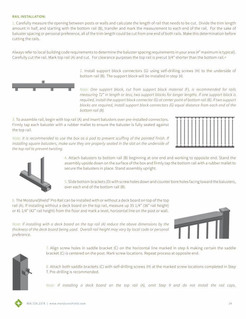
LEVEL RAIL POSTS INSTALLATION:
1. Measure and locate the position of the post(s) based on the project layout.
Note: If an over-the-post installation is desired, the post will need to be cut from the standard length to accomplish this. To determine this height, place the post in the desired locations to be installed, and mark for the bracket location as instructed in step 7. Then, mark a line 3/4” above the bracket location marks. This will be the location to cut the post and permit the top rail to be installed flush with the top of the post and allow a deck board to be installed over the top of the post.
2. Install the post by attaching the aluminum mounting flange to the surface of the deck or balcony. Position the post so the fastener will go into the floor joist, and make sure the decking is firmly attached to the joist at the location of the post. If necessary, use wood blocking as reinforcement underneath the decking where the posts are located. Post mounting fasteners should be able to secure into the joist or reinforcement braces, not just the decking itself. When installing MoistureShield Pro Rail Post on top of a wood surface, screws must be lagged into at least 3” of solid wood. Deck boards sized 5/4” or 1 1/2” do not provide sufficient material for a safe installation.
Note: When installing MoistureShield® Pro Rail Post onto treated wood surface, install the provided ACQ pad (included in the post kit) between the post base and the treated surface.
3. Position the post to the deck surface. Four 3/8” diameter mounting holes are provided on the mounting flange. Mark the mounting flange hole locations and remove the post. Drill the marked locations into the decking and reinforcement using the proper size drill required for the fasteners being used. Remount the post. Insert the appropriate fasteners to secure the mounting flange to the deck structure.
4. Finish by sliding the base trim to the bottom of the post to cover the mounting flange.
5. To install the post cap, set it in place on top of the post and strike with a rubber mallet to drive the post cap onto the post. Silicone or water based caulking may be used to secure the post cap and base trim.
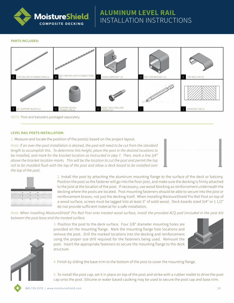
NOTE: Post and balusters packaged separately.
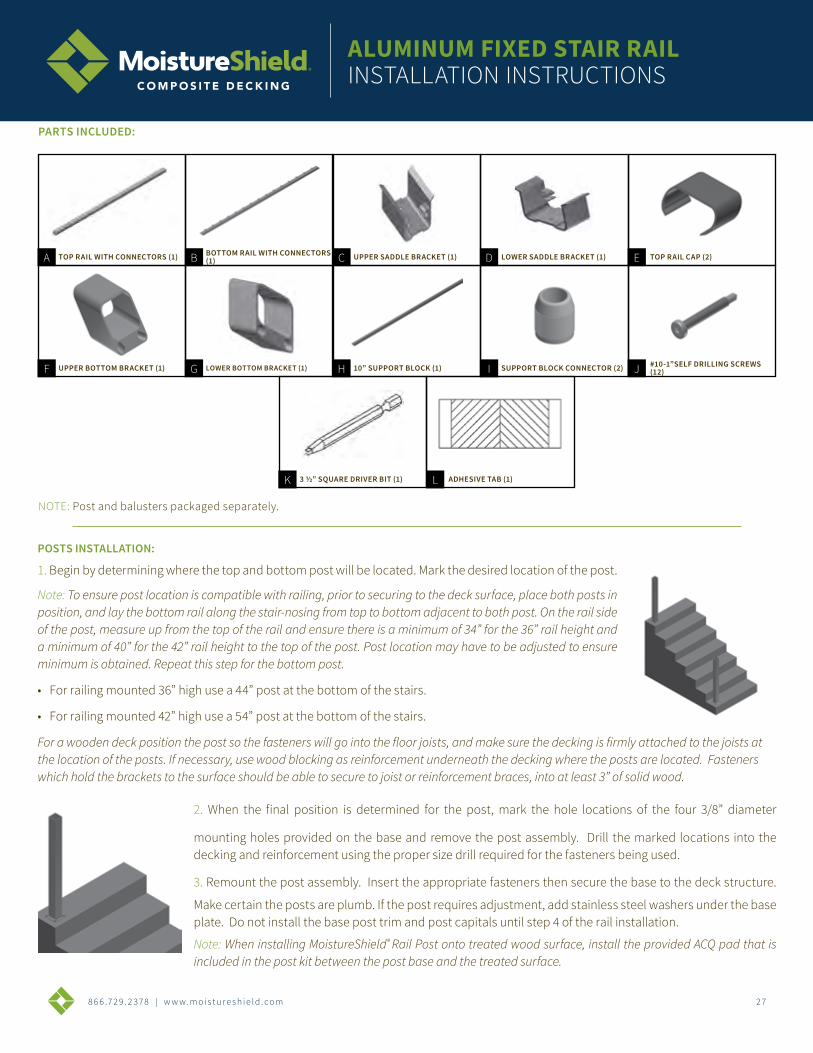
PARTS INCLUDED:
TOP RAIL WITH CONNECTORS (1)A BOTTOM RAIL WITH CONNECTORS (1)B C D E
10” SUPPORT BLOCK (1)F SUPPORT BLOCK CONNECTOR (2)G H I J
SADDLE BRACKET (2) BOTTOM BRACKET (2) TOP RAIL CAP (2)
#10X1” SELF DRILLING SCREW (12)
3 ½” SQUARE DRIVER BIT (1)
ADHESIVE TAB (1)
ALUMINUM LEVEL RAILINSTALLATION INSTRUCTIONS
8 6 6 .7 2 9 . 2 3 7 8 | w w w. m o i s t u r e s h i e l d . c o m 24
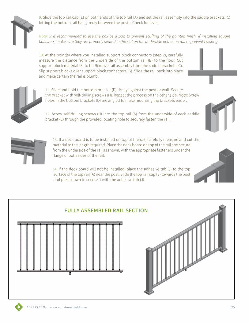
RAIL INSTALLATION:
1. Carefully measure the opening between posts or walls and calculate the length of rail that needs to be cut. Divide the trim length amount in half, and starting with the bottom rail (B), transfer and mark the measurement to each end of the rail. For the sake of baluster spacing or personal preference, all of the trim length could be cut from one end of both rails. Make this determination before cutting the rails.
Always refer to local building code requirements to determine the baluster spacing requirements in your area (4” maximum is typical). Carefully cut the rail. Mark top rail (A) and cut. For clearance purposes the top rail is precut 3/4” shorter than the bottom rail.=
2. Install support block connectors (G) using self-drilling screws (H) to the underside of bottom rail (B). The support block will be installed in step 10.
Note: One support block, cut from support block material (F), is recommended for rails measuring 72” in length or less; two support blocks for longer lengths. If one support block is required, install the support block connector (G) at center point of bottom rail (B]. If two support blocks are required, install support block connectors (G) equal distance from each end of the bottom rail (B).
3. To assemble rail, begin with top rail (A) and insert balusters over pre-installed connectors. Firmly tap each baluster with a rubber mallet to ensure the baluster is fully seated against the top rail.
Note: It is recommended to use the box as a pad to prevent scuffing of the painted finish. If installing square balusters, make sure they are properly seated in the slot on the underside of the top rail to prevent twisting.
4. Attach balusters to bottom rail (B) beginning at one end and working to opposite end. Stand the assembly upside down on the surface of the box and firmly tap the bottom rail with a rubber mallet to secure the balusters in place. Stand assembly upright.
5. Slide bottom brackets (D) with screw holes down and counter bore holes facing toward the balusters, over each end of the bottom rail (B).
6. The MoistureShield® Pro Rail can be installed with or without a deck board on top of the top rail (A). If installing without a deck board on the top rail, measure up 35 1/4” (36” rail height) or 41 1/4” (42” rail height) from the floor and mark a level, horizontal line on the post or wall.
Note: If installing with a deck board on the top rail (A) reduce the above dimensions by the thickness of the deck board being used. Overall rail height may vary by local code or personal preference.
7. Align screw holes in saddle bracket (C) on the horizontal line marked in step 6 making certain the saddle bracket (C) is centered on the post. Mark screw locations. Repeat process at opposite end.
8. Attach both saddle brackets (C) with self-drilling screws (H) at the marked screw locations completed in Step 7. Pre-drilling is recommended.
Note: If installing a deck board on the top rail (A), omit Step 9 and do not install the rail caps.
8 6 6 .7 2 9 . 2 3 7 8 | w w w. m o i s t u r e s h i e l d . c o m 2 5
9. Slide the top rail cap (E) on both ends of the top rail (A) and set the rail assembly into the saddle brackets (C) letting the bottom rail hang freely between the posts. Check for level.
Note: It is recommended to use the box as a pad to prevent scuffing of the painted finish. If installing square balusters, make sure they are properly seated in the slot on the underside of the top rail to prevent twisting.
10. At the point(s) where you installed support block connectors (step 2), carefully measure the distance from the underside of the bottom rail (B) to the floor. Cut support block material (F) to fit. Remove rail assembly from the saddle brackets (C). Slip support blocks over support block connectors (G). Slide the rail back into place
and make certain the rail is plumb.
11. Slide and hold the bottom bracket (D) firmly against the post or wall. Secure the bracket with self-drilling screws (H). Repeat the process on the other side. Note: Screw holes in the bottom brackets (D) are angled to make mounting the brackets easier.
12. Screw self-drilling screws (H) into the top rail (A) from the underside of each saddle bracket (C) through the provided locating hole to securely fasten the rail.
13. If a deck board is to be installed on top of the rail, carefully measure and cut the material to the length required. Place the deck board on top of the rail and secure from the underside of the rail as shown, with the appropriate fasteners under the flange of both sides of the rail.
14. If the deck board will not be installed, place the adhesive tab (J) to the top surface of the top rail (A) near the post. Slide the top rail cap (E) towards the post and press down to secure it with the adhesive tab (J).
FULLY ASSEMBLED RAIL SECTION
8 6 6 .7 2 9 . 2 3 7 8 | w w w. m o i s t u r e s h i e l d . c o m 2 6
TOOLS REQUIRED:• Drill bit 5/32” (.156”)
• Drill (with adjustable clutch, recommended)
• Miter Saw (with metal cutting blade)
• Level
• Rubber mallet
• Tape measure
• Touch-up paint
FOR A SUCCESSFUL INSTALLATION:• Read the instructions completely before beginning the installation.
• Plan your railing project. Sketch your project with the actual measurements of your deck or balcony complete with post locations.
• Check local building codes to ensure compliance.
• Check carton(s) to determine part count is complete.
• After cutting rails, balusters, or posts, paint exposed metal for maximum protection against the elements.
• Installation is best accomplished with two people.
• Wear personal protection equipment; safety glasses, etc.
• Use care not to over-torque the screws. Pre-drilling is recommended.
• Provided hardware to install MoistureShield® Pro Aluminum Rail is for use with MoistureShield® Pro Aluminum Posts. If installing to other surfaces the installer must acquire the appropriate hardware as needed for proper installation.
ALUMINUM FIXED STAIR RAILINSTALLATION INSTRUCTIONS
8 6 6 .7 2 9 . 2 3 7 8 | w w w. m o i s t u r e s h i e l d . c o m 27
POSTS INSTALLATION:
1. Begin by determining where the top and bottom post will be located. Mark the desired location of the post.
Note: To ensure post location is compatible with railing, prior to securing to the deck surface, place both posts in position, and lay the bottom rail along the stair-nosing from top to bottom adjacent to both post. On the rail side of the post, measure up from the top of the rail and ensure there is a minimum of 34” for the 36” rail height and a minimum of 40” for the 42” rail height to the top of the post. Post location may have to be adjusted to ensure minimum is obtained. Repeat this step for the bottom post.
• For railing mounted 36” high use a 44” post at the bottom of the stairs.
• For railing mounted 42” high use a 54” post at the bottom of the stairs.
For a wooden deck position the post so the fasteners will go into the floor joists, and make sure the decking is firmly attached to the joists at the location of the posts. If necessary, use wood blocking as reinforcement underneath the decking where the posts are located. Fasteners which hold the brackets to the surface should be able to secure to joist or reinforcement braces, into at least 3” of solid wood.
2. When the final position is determined for the post, mark the hole locations of the four 3/8” diameter
mounting holes provided on the base and remove the post assembly. Drill the marked locations into the decking and reinforcement using the proper size drill required for the fasteners being used.
3. Remount the post assembly. Insert the appropriate fasteners then secure the base to the deck structure.
Make certain the posts are plumb. If the post requires adjustment, add stainless steel washers under the base plate. Do not install the base post trim and post capitals until step 4 of the rail installation.
Note: When installing MoistureShield® Rail Post onto treated wood surface, install the provided ACQ pad that is included in the post kit between the post base and the treated surface.
NOTE: Post and balusters packaged separately.
PARTS INCLUDED:
TOP RAIL WITH CONNECTORS (1)A BOTTOM RAIL WITH CONNECTORS (1)B C D E
UPPER BOTTOM BRACKET (1)F LOWER BOTTOM BRACKET (1)G H I J
UPPER SADDLE BRACKET (1) LOWER SADDLE BRACKET (1) TOP RAIL CAP (2)
10” SUPPORT BLOCK (1) SUPPORT BLOCK CONNECTOR (2) #10-1”SELF DRILLING SCREWS (12)
K L3 ½” SQUARE DRIVER BIT (1) ADHESIVE TAB (1)
ALUMINUM FIXED STAIR RAILINSTALLATION INSTRUCTIONS
8 6 6 .7 2 9 . 2 3 7 8 | w w w. m o i s t u r e s h i e l d . c o m 2 8
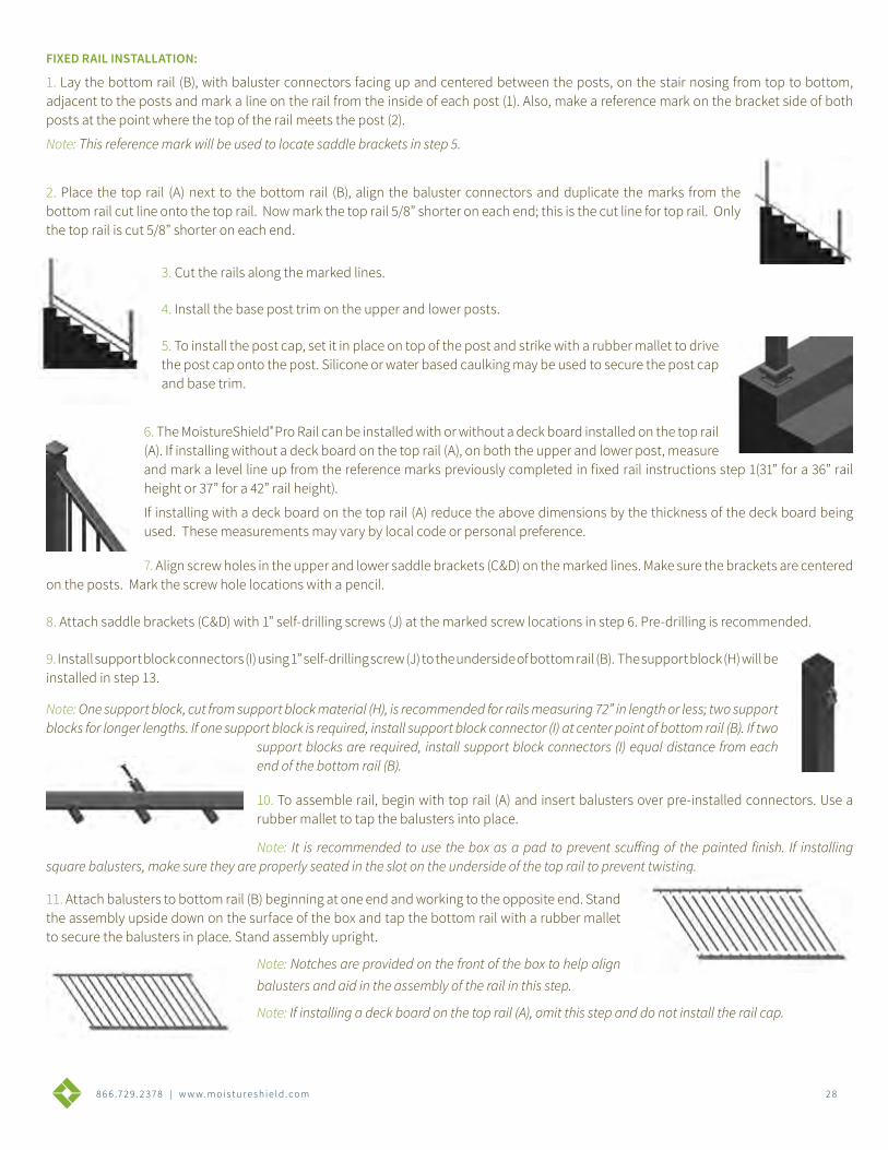
FIXED RAIL INSTALLATION:
1. Lay the bottom rail (B), with baluster connectors facing up and centered between the posts, on the stair nosing from top to bottom, adjacent to the posts and mark a line on the rail from the inside of each post (1). Also, make a reference mark on the bracket side of both posts at the point where the top of the rail meets the post (2).
Note: This reference mark will be used to locate saddle brackets in step 5.
2. Place the top rail (A) next to the bottom rail (B), align the baluster connectors and duplicate the marks from the bottom rail cut line onto the top rail. Now mark the top rail 5/8” shorter on each end; this is the cut line for top rail. Only the top rail is cut 5/8” shorter on each end.
3. Cut the rails along the marked lines.
4. Install the base post trim on the upper and lower posts.
5. To install the post cap, set it in place on top of the post and strike with a rubber mallet to drive the post cap onto the post. Silicone or water based caulking may be used to secure the post cap and base trim.
6. The MoistureShield® Pro Rail can be installed with or without a deck board installed on the top rail (A). If installing without a deck board on the top rail (A), on both the upper and lower post, measure and mark a level line up from the reference marks previously completed in fixed rail instructions step 1(31” for a 36” rail height or 37” for a 42” rail height).
If installing with a deck board on the top rail (A) reduce the above dimensions by the thickness of the deck board being used. These measurements may vary by local code or personal preference.
7. Align screw holes in the upper and lower saddle brackets (C&D) on the marked lines. Make sure the brackets are centered on the posts. Mark the screw hole locations with a pencil.
8. Attach saddle brackets (C&D) with 1” self-drilling screws (J) at the marked screw locations in step 6. Pre-drilling is recommended.
9. Install support block connectors (I) using 1” self-drilling screw (J) to the underside of bottom rail (B). The support block (H) will be installed in step 13.
Note: One support block, cut from support block material (H), is recommended for rails measuring 72” in length or less; two support blocks for longer lengths. If one support block is required, install support block connector (I) at center point of bottom rail (B). If two
support blocks are required, install support block connectors (I) equal distance from each end of the bottom rail (B).
10. To assemble rail, begin with top rail (A) and insert balusters over pre-installed connectors. Use a rubber mallet to tap the balusters into place.
Note: It is recommended to use the box as a pad to prevent scuffing of the painted finish. If installing square balusters, make sure they are properly seated in the slot on the underside of the top rail to prevent twisting.
11. Attach balusters to bottom rail (B) beginning at one end and working to the opposite end. Stand the assembly upside down on the surface of the box and tap the bottom rail with a rubber mallet to secure the balusters in place. Stand assembly upright.
Note: Notches are provided on the front of the box to help align balusters and aid in the assembly of the rail in this step.
Note: If installing a deck board on the top rail (A), omit this step and do not install the rail cap.
8 6 6 .7 2 9 . 2 3 7 8 | w w w. m o i s t u r e s h i e l d . c o m 2 9
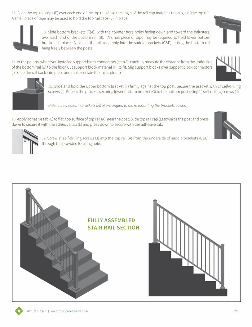
12. Slide the top rail caps (E) over each end of the top rail (A) so the angle of the rail cap matches the angle of the top rail. A small piece of tape may be used to hold the top rail caps (E) in place.
13. Slide bottom brackets (F&G) with the counter bore holes facing down and toward the balusters, over each end of the bottom rail (B). A small piece of tape may be required to hold lower bottom brackets in place. Next, set the rail assembly into the saddle brackets (C&D) letting the bottom rail hang freely between the posts.
14. At the point(s) where you installed support block connectors (step 8), carefully measure the distance from the underside of the bottom rail (B) to the floor. Cut support block material (H) to fit. Slip support blocks over support block connectors (I). Slide the rail back into place and make certain the rail is plumb.
15. Slide and hold the upper bottom bracket (F) firmly against the top post. Secure the bracket with 1” self-drilling screws (J). Repeat the process securing lower bottom bracket (G) to the bottom post using 1” self-drilling screws (J).
Note: Screw holes in brackets (F&G) are angled to make mounting the brackets easier.
16. Apply adhesive tab (L) to flat, top surface of top rail (A), near the post. Slide top rail cap (E) towards the post and press down to secure it with the adhesive tab (L) and press down to secure with the adhesive tab.
17. Screw 1” self-drilling screws (J) into the top rail (A) from the underside of saddle brackets (C&D) through the provided locating hole.
FULLY ASSEMBLED STAIR RAIL SECTION

BULLET LIGHTSINSTALLATION INSTRUCTIONS
TOOLS:• Power Drill
• 1-1/8” spade bit or forstner bit
• ¾” spade bit or forstner bit
• Two Wood Screws
• Screwdriver
• Chisel
• Pliers
• Tape Measure
• Clear silicone caulk or sealant
• Eye protection
REQUIREMENTS:Before you begin, make sure you have an external, weatherproof, protected 110 volt outlet that meets GFCI (ground fault circuit interrupter) standards. Mount the transformer 18 inches above the ground. Best results can be achieved when you have access to the underside of your deck or installation surface. Do not install more than 40 MoistureShield® bullet lights on one transformer.
COMPLETE KIT INCLUDES:• 10 LED Flush-mount Deck/Stair Lights
• 27 Connectors
• 100’ of Twisted Wire
• Transformer (Capacity up to 40 lights)
• Remote Driver
• Remote Control
8 6 6 .7 2 9 . 2 3 7 8 | w w w. m o i s t u r e s h i e l d . c o m 3 0
8 6 6 .7 2 9 . 2 3 7 8 | w w w. m o i s t u r e s h i e l d . c o m 31
BULLET LIGHTSINSTALLATION INSTRUCTIONS
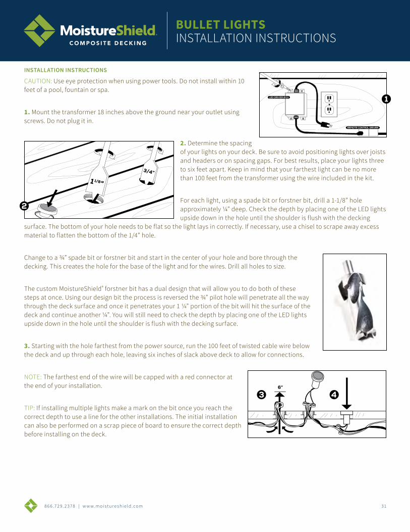
INSTALLATION INSTRUCTIONS
CAUTION: Use eye protection when using power tools. Do not install within 10 feet of a pool, fountain or spa.
1. Mount the transformer 18 inches above the ground near your outlet using screws. Do not plug it in.
2. Determine the spacing of your lights on your deck. Be sure to avoid positioning lights over joists and headers or on spacing gaps. For best results, place your lights three to six feet apart. Keep in mind that your farthest light can be no more than 100 feet from the transformer using the wire included in the kit.
For each light, using a spade bit or forstner bit, drill a 1-1/8” hole approximately ¼” deep. Check the depth by placing one of the LED lights upside down in the hole until the shoulder is flush with the decking
surface. The bottom of your hole needs to be flat so the light lays in correctly. If necessary, use a chisel to scrape away excess material to flatten the bottom of the 1/4” hole.
Change to a ¾” spade bit or forstner bit and start in the center of your hole and bore through the decking. This creates the hole for the base of the light and for the wires. Drill all holes to size.
The custom MoistureShield® forstner bit has a dual design that will allow you to do both of these steps at once. Using our design bit the process is reversed the ¾” pilot hole will penetrate all the way through the deck surface and once it penetrates your 1 ¼” portion of the bit will hit the surface of the deck and continue another ¼”. You will still need to check the depth by placing one of the LED lights upside down in the hole until the shoulder is flush with the decking surface.
3. Starting with the hole farthest from the power source, run the 100 feet of twisted cable wire below the deck and up through each hole, leaving six inches of slack above deck to allow for connections.
NOTE: The farthest end of the wire will be capped with a red connector at the end of your installation.
TIP: If installing multiple lights make a mark on the bit once you reach the correct depth to use a line for the other installations. The initial installation can also be performed on a scrap piece of board to ensure the correct depth before installing on the deck.
1 ”1/8
3/4”
REMOTE CONTROL DRIVER
LED DRIVER BOX
6”
8 6 6 .7 2 9 . 2 3 7 8 | w w w. m o i s t u r e s h i e l d . c o m 3 2
BULLET LIGHTSINSTALLATION INSTRUCTIONS
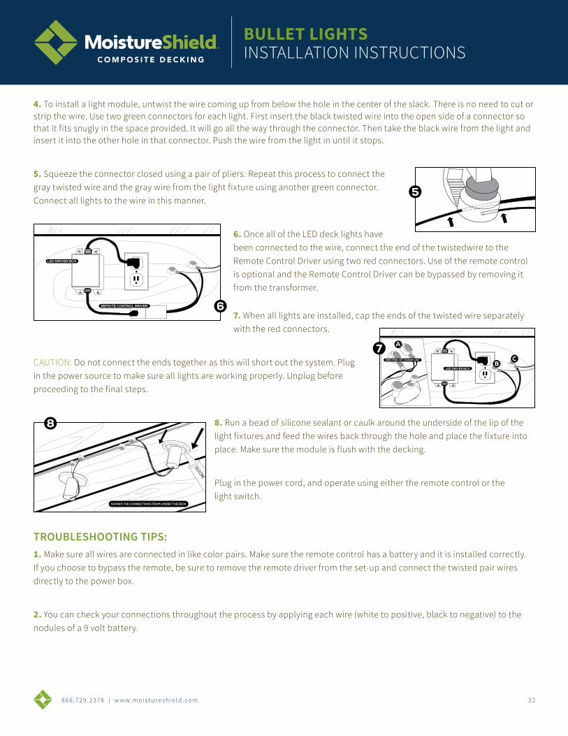
4. To install a light module, untwist the wire coming up from below the hole in the center of the slack. There is no need to cut or strip the wire. Use two green connectors for each light. First insert the black twisted wire into the open side of a connector so that it fits snugly in the space provided. It will go all the way through the connector. Then take the black wire from the light and insert it into the other hole in that connector. Push the wire from the light in until it stops.
5. Squeeze the connector closed using a pair of pliers. Repeat this process to connect the gray twisted wire and the gray wire from the light fixture using another green connector. Connect all lights to the wire in this manner.
6. Once all of the LED deck lights have been connected to the wire, connect the end of the twistedwire to the Remote Control Driver using two red connectors. Use of the remote control is optional and the Remote Control Driver can be bypassed by removing it from the transformer.
7. When all lights are installed, cap the ends of the twisted wire separately with the red connectors.
CAUTION: Do not connect the ends together as this will short out the system. Plug in the power source to make sure all lights are working properly. Unplug before proceeding to the final steps.
8. Run a bead of silicone sealant or caulk around the underside of the lip of the light fixtures and feed the wires back through the hole and place the fixture into place. Make sure the module is flush with the decking.
Plug in the power cord, and operate using either the remote control or the light switch.
TROUBLESHOOTING TIPS:1. Make sure all wires are connected in like color pairs. Make sure the remote control has a battery and it is installed correctly. If you choose to bypass the remote, be sure to remove the remote driver from the set-up and connect the twisted pair wires directly to the power box.
2. You can check your connections throughout the process by applying each wire (white to positive, black to negative) to the nodules of a 9 volt battery.
LED DRIVER BOX
RED END OF CHAIN CAP
A
BC
SHOWS THE CONNECTIONS FROM UNDER THE DECK
SILICONE
LED DRIVER BOX
REMOTE CONTROL DRIVER
8 6 6 .7 2 9 . 2 3 7 8 | w w w. m o i s t u r e s h i e l d . c o m 3 3
DECK CLIP SYSTEMINSTALLATION INSTRUCTIONS
COMPLETE SYSTEMCOVERS 50 SQUARE FEET OF DECKING
• 5 starter clips
• 5 finish clips
• 90 clips
• 90 screws or 90 pneumatic fasteners
DECK/CONTRACTOR PACKCOVERS 250 SQUARE FEET OF DECKING
• 450 clips
• 500 screws (Deck Pack) or 500 pneumatic fasteners (Contractor Pack) *Does not include starter or finish clips
866.729.2378 | WWW.MOISTURESHIELD.COM
BENEFITS:• Easiest clip to install with square drive ACQ compatible screws or pneumatic fasteners
• Concealed deck clips allow for an unblemished deck surface
• Base of clip elevates board off the joists, reducing rot, mold, ice shear and lateral load stress
• Automatically spaces the deck boards 3/16” for a uniform appearance
• Limited Lifetime Warranty against loose deck boards
• Available in high strength steel with a patented coating process to resist corrosion or 304 grade stainless steel for coastal applications
• Approved for ACQ joists and all other PT joists
*All clips available in stainless steel
STRIP LIGHTSINSTALLATION INSTRUCTIONS
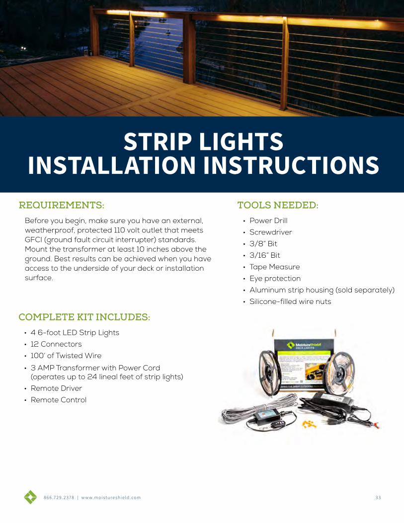
COMPLETE KIT INCLUDES:• 4 6-foot LED Strip Lights
• 12 Connectors
• 100’ of Twisted Wire
• 3 AMP Transformer with Power Cord (operates up to 24 lineal feet of strip lights)
• Remote Driver
• Remote Control
TOOLS NEEDED:• Power Drill
• Screwdriver
• 3/8” Bit
• 3/16” Bit
• Tape Measure
• Eye protection
• Aluminum strip housing (sold separately)
• Silicone-filled wire nuts
REQUIREMENTS:Before you begin, make sure you have an external, weatherproof, protected 110 volt outlet that meets GFCI (ground fault circuit interrupter) standards. Mount the transformer at least 10 inches above the ground. Best results can be achieved when you have access to the underside of your deck or installation surface.
STRIP LIGHTS INSTALLATION INSTRUCTIONS
8 6 6 .7 2 9 . 2 3 7 8 | w w w. m o i s t u r e s h i e l d . c o m 3 4
DECK CLIP SYSTEMINSTALLATION INSTRUCTIONS
COMPLETE SYSTEMCOVERS 50 SQUARE FEET OF DECKING
• 5 starter clips
• 5 finish clips
• 90 clips
• 90 screws or 90 pneumatic fasteners
DECK/CONTRACTOR PACKCOVERS 250 SQUARE FEET OF DECKING
• 450 clips
• 500 screws (Deck Pack) or 500 pneumatic fasteners (Contractor Pack) *Does not include starter or finish clips
866.729.2378 | WWW.MOISTURESHIELD.COM
BENEFITS:• Easiest clip to install with square drive ACQ compatible screws or pneumatic fasteners
• Concealed deck clips allow for an unblemished deck surface
• Base of clip elevates board off the joists, reducing rot, mold, ice shear and lateral load stress
• Automatically spaces the deck boards 3/16” for a uniform appearance
• Limited Lifetime Warranty against loose deck boards
• Available in high strength steel with a patented coating process to resist corrosion or 304 grade stainless steel for coastal applications
• Approved for ACQ joists and all other PT joists
*All clips available in stainless steel
STRIP LIGHTSINSTALLATION INSTRUCTIONS
CAUTION: Use eye protection when using power tools. Do not install within 10 feet of a pool, fountain or spa.
TRANSFORMER INSTALLATION:
1. Start by determining and marking where each fixture is to be installed. Next, determine the sequence in which the main line will run. The fixtures should run in sequence and the total wattage of each run should not exceed the transformer’s circuit.
Total wattage is determined by multiplying feet of strip lights by wattage in each foot. (6 feet with 1.5 watts per foot, 6x1.5 = 9 watts per 6’ strip). Refer to your specific transformer to determine the circuit’s allowable wattage.
2. Using the installation instructions that are provided the the transformer, mount transformer to the house and install main power feed line. This line should be a UV-resistant, UL-approved 12-2 low voltage cable with a 100’ max run and no more than 250 watts. If run is more than 100’ and over 250 watts, use 10-2 or 8-2 wire to carry the load. Be sure main line is long enough to reach the first lighting fixture.
3. Drill a 3/8” hole through the deck surface and feed main line through to the under side of the deck. Next, run the main wire to your first fixture. Secure the main wire using insulated staples or cable tacks.
TIP: For faster installation, pre-wire the main run before decking is installed.
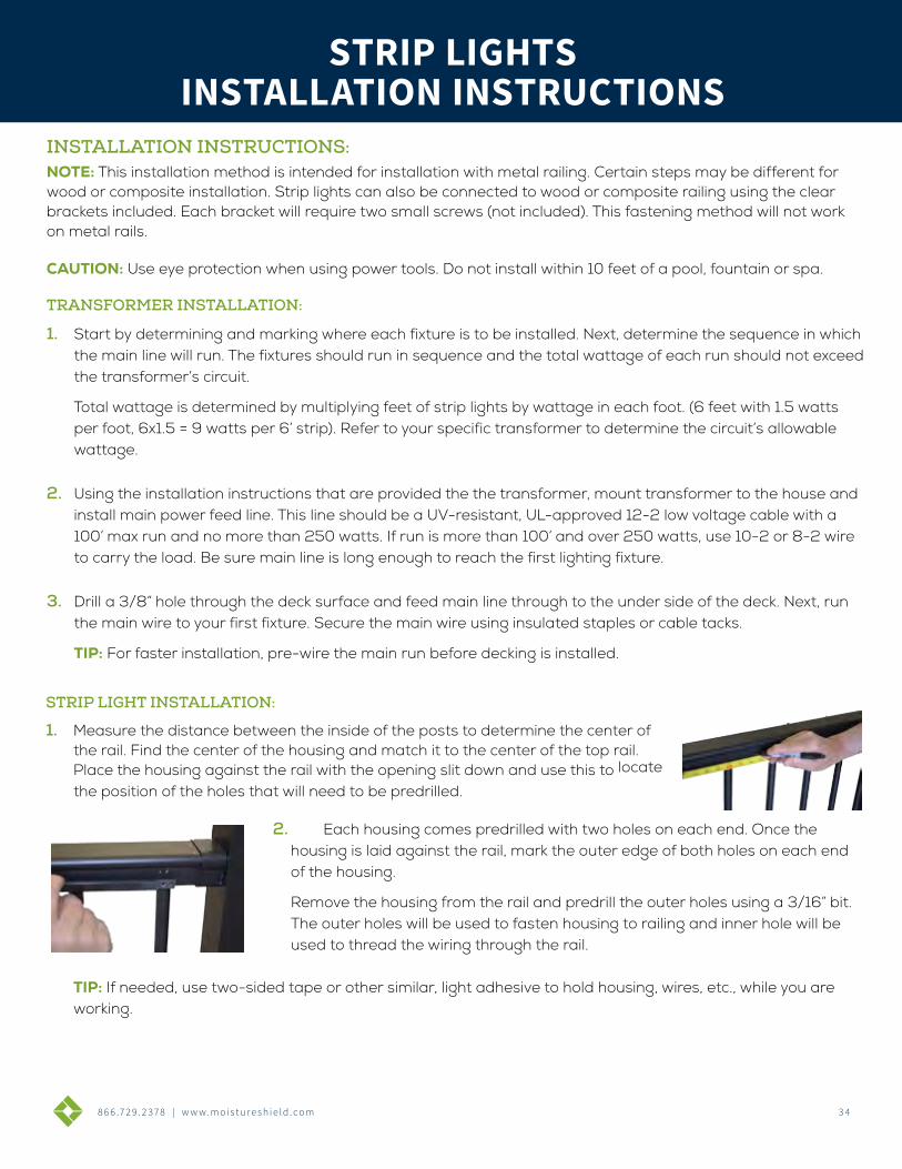
1. Measure the distance between the inside of the posts to determine the center of the rail. Find the center of the housing and match it to the center of the top rail. Place the housing against the rail with the opening slit down and use this to locate
the position of the holes that will need to be predrilled.
2. Each housing comes predrilled with two holes on each end. Once the housing is laid against the rail, mark the outer edge of both holes on each end of the housing.
Remove the housing from the rail and predrill the outer holes using a 3/16” bit. The outer holes will be used to fasten housing to railing and inner hole will be used to thread the wiring through the rail.
TIP: If needed, use two-sided tape or other similar, light adhesive to hold housing, wires, etc., while you are working.
INSTALLATION INSTRUCTIONS:NOTE: This installation method is intended for installation with metal railing. Certain steps may be different for wood or composite installation. Strip lights can also be connected to wood or composite railing using the clear brackets included. Each bracket will require two small screws (not included). This fastening method will not work on metal rails.
STRIP LIGHT INSTALLATION:
STRIP LIGHTS INSTALLATION INSTRUCTIONS
8 6 6 .7 2 9 . 2 3 7 8 | w w w. m o i s t u r e s h i e l d . c o m 3 5
DECK CLIP SYSTEMINSTALLATION INSTRUCTIONS
COMPLETE SYSTEMCOVERS 50 SQUARE FEET OF DECKING
• 5 starter clips
• 5 finish clips
• 90 clips
• 90 screws or 90 pneumatic fasteners
DECK/CONTRACTOR PACKCOVERS 250 SQUARE FEET OF DECKING
• 450 clips
• 500 screws (Deck Pack) or 500 pneumatic fasteners (Contractor Pack) *Does not include starter or finish clips
866.729.2378 | WWW.MOISTURESHIELD.COM
BENEFITS:• Easiest clip to install with square drive ACQ compatible screws or pneumatic fasteners
• Concealed deck clips allow for an unblemished deck surface
• Base of clip elevates board off the joists, reducing rot, mold, ice shear and lateral load stress
• Automatically spaces the deck boards 3/16” for a uniform appearance
• Limited Lifetime Warranty against loose deck boards
• Available in high strength steel with a patented coating process to resist corrosion or 304 grade stainless steel for coastal applications
• Approved for ACQ joists and all other PT joists
*All clips available in stainless steel
STRIP LIGHTSINSTALLATION INSTRUCTIONS
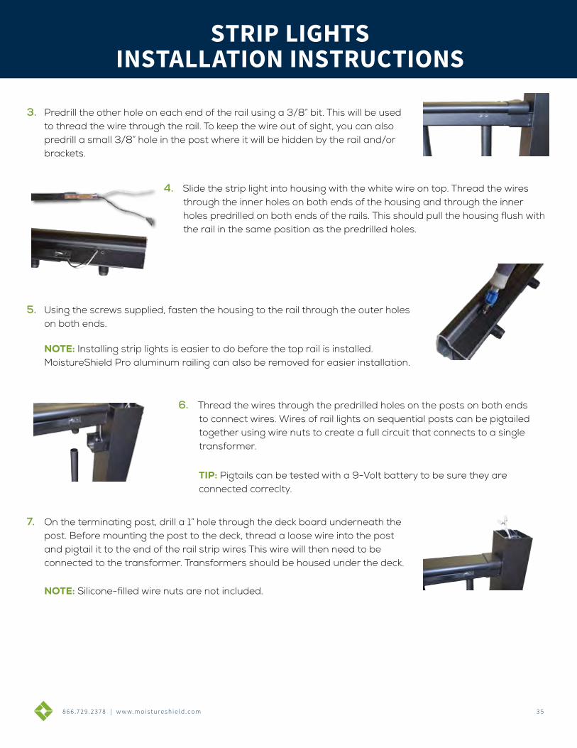
3. Predrill the other hole on each end of the rail using a 3/8” bit. This will be used to thread the wire through the rail. To keep the wire out of sight, you can also predrill a small 3/8” hole in the post where it will be hidden by the rail and/or brackets.
4. Slide the strip light into housing with the white wire on top. Thread the wires through the inner holes on both ends of the housing and through the inner holes predrilled on both ends of the rails. This should pull the housing flush with the rail in the same position as the predrilled holes.
5. Using the screws supplied, fasten the housing to the rail through the outer holes on both ends.
NOTE: Installing strip lights is easier to do before the top rail is installed. MoistureShield Pro aluminum railing can also be removed for easier installation.
6. Thread the wires through the predrilled holes on the posts on both ends to connect wires. Wires of rail lights on sequential posts can be pigtailed together using wire nuts to create a full circuit that connects to a single transformer.
TIP: Pigtails can be tested with a 9-Volt battery to be sure they are connected correclty.
7. On the terminating post, drill a 1” hole through the deck board underneath the post. Before mounting the post to the deck, thread a loose wire into the post and pigtail it to the end of the rail strip wires This wire will then need to be connected to the transformer. Transformers should be housed under the deck.
NOTE: Silicone-filled wire nuts are not included.
STRIP LIGHTS INSTALLATION INSTRUCTIONS
8 6 6 .7 2 9 . 2 3 7 8 | w w w. m o i s t u r e s h i e l d . c o m 3 6
STAIR LIGHTSINSTALLATION INSTRUCTIONS
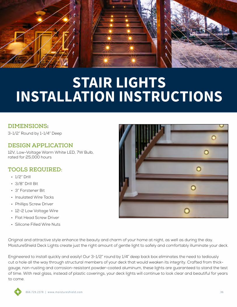
DIMENSIONS:3-1/2” Round by 1-1/4” Deep
TOOLS REQUIRED:• 1/2” Drill
• 3/8” Drill Bit
• 3” Forstener Bit
• Insulated Wire Tacks
• Phillips Screw Driver
• 12-2 Low Voltage Wire
• Flat Head Screw Driver
• Silicone Filled Wire Nuts
DESIGN APPLICATION12V, Low-Voltage Warm White LED, 7W Bulb, rated for 25,000 hours
Original and attractive style enhance the beauty and charm of your home at night, as well as during the day. MoistureShield Deck Lights create just the right amount of gentle light to safely and comfortably illuminate your deck.
Engineered to install quickly and easily! Our 3-1/2” round by 1/4” deep back box eliminates the need to tediously cut a hole all the way through structural members of your deck that would weaken its integrity. Crafted from thick-gauge, non-rusting and corrosion-resistant powder-coated aluminum, these lights are guaranteed to stand the test of time. With real glass, instead of plastic coverings, your deck lights will continue to look clear and beautiful for years to come.
STAIR LIGHTS INSTALLATION INSTRUCTIONS
8 6 6 .7 2 9 . 2 3 7 8 | w w w. m o i s t u r e s h i e l d . c o m 3 7
DECK CLIP SYSTEMINSTALLATION INSTRUCTIONS
COMPLETE SYSTEMCOVERS 50 SQUARE FEET OF DECKING
• 5 starter clips
• 5 finish clips
• 90 clips
• 90 screws or 90 pneumatic fasteners
DECK/CONTRACTOR PACKCOVERS 250 SQUARE FEET OF DECKING
• 450 clips
• 500 screws (Deck Pack) or 500 pneumatic fasteners (Contractor Pack) *Does not include starter or finish clips
866.729.2378 | WWW.MOISTURESHIELD.COM
BENEFITS:• Easiest clip to install with square drive ACQ compatible screws or pneumatic fasteners
• Concealed deck clips allow for an unblemished deck surface
• Base of clip elevates board off the joists, reducing rot, mold, ice shear and lateral load stress
• Automatically spaces the deck boards 3/16” for a uniform appearance
• Limited Lifetime Warranty against loose deck boards
• Available in high strength steel with a patented coating process to resist corrosion or 304 grade stainless steel for coastal applications
• Approved for ACQ joists and all other PT joists
*All clips available in stainless steel
INSTALLATION INSTRUCTIONS
CAUTION: Use eye protection when using power tools. Do not install within 10 feet of a pool, fountain or spa.
1. Start by determining and marking where each fixture is to be installed. Next, determine the sequence in which the main line will run. The fixtures should run in sequence and the total wattage of each run should not ex-ceed the transformer’s circuit.
Total wattage is determined by multiplying # of fixtures by wattage of bulb in each fixture. (9 lights with 7 watt bulbs, 9x7 = 63 watts total). Refer to your specific transformer to determine the circuit’s allowable wattage.
2. Using the installation instructions that are provided with the transformer, mount transformer to the house and install main power feed line. This line should be a UV-resistant, UL-approved 12-2 low voltage cable with a 100’ max run and no more than 250 watts. If run is more than 100’ and over 250 watts, use 10-2 or 8-2 wire to carry the load. Be sure the main line is long enough to reach the first lighting fixture.
3. Drill a 3/8” hole through the deck surface and feed main line through to the under side of the deck. Next, run the main wire to your first fixture. Secure the main wire using insulated staples or cable tacks.
TIP: For faster installation, pre-wire the main run before decking is installed.
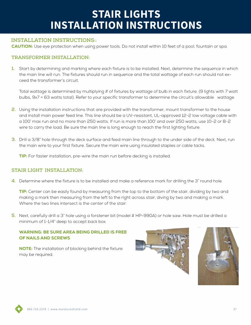
STAIR LIGHT INSTALLATION:
4. Determine where the fixture is to be installed and make a reference mark for drilling the 3” round hole.
TIP: Center can be easily found by measuring from the top to the bottom of the stair, dividing by two and making a mark then measuring from the left to the right across stair, diving by two and making a mark. Where the two lines intersect is the center of the stair.
5. Next, carefully drill a 3” hole using a forstener bit (model # HP-990A) or hole saw. Hole must be drilled a minimum of 1-1/4” deep to accept back box.
WARNING: BE SURE AREA BEING DRILLED IS FREE OF NAILS AND SCREWS
NOTE: The installation of blocking behind the fixture may be required.
INSTALLATION INSTRUCTIONS::
STAIR LIGHTS
TRANSFORMER INSTALLATION:
STAIR LIGHTS INSTALLATION INSTRUCTIONS
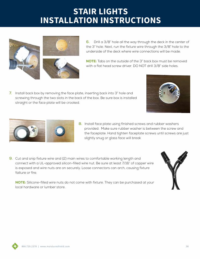
8 6 6 .7 2 9 . 2 3 7 8 | w w w. m o i s t u r e s h i e l d . c o m 3 8
DECK CLIP SYSTEMINSTALLATION INSTRUCTIONS
COMPLETE SYSTEMCOVERS 50 SQUARE FEET OF DECKING
• 5 starter clips
• 5 finish clips
• 90 clips
• 90 screws or 90 pneumatic fasteners
DECK/CONTRACTOR PACKCOVERS 250 SQUARE FEET OF DECKING
• 450 clips
• 500 screws (Deck Pack) or 500 pneumatic fasteners (Contractor Pack) *Does not include starter or finish clips
866.729.2378 | WWW.MOISTURESHIELD.COM
BENEFITS:• Easiest clip to install with square drive ACQ compatible screws or pneumatic fasteners
• Concealed deck clips allow for an unblemished deck surface
• Base of clip elevates board off the joists, reducing rot, mold, ice shear and lateral load stress
• Automatically spaces the deck boards 3/16” for a uniform appearance
• Limited Lifetime Warranty against loose deck boards
• Available in high strength steel with a patented coating process to resist corrosion or 304 grade stainless steel for coastal applications
• Approved for ACQ joists and all other PT joists
*All clips available in stainless steel
INSTALLATION INSTRUCTIONS
6. Drill a 3/8” hole all the way through the deck in the center of the 3” hole. Next, run the fixture wire through the 3/8” hole to the underside of the deck where wire connections will be made.
NOTE: Tabs on the outside of the 3” back box must be removed with a flat head screw driver. DO NOT drill 3/8” side holes.
7. Install back box by removing the face plate, inserting back into 3” hole and screwing through the two slots in the back of the box. Be sure box is installed straight or the face plate will be crooked.
8. Install face plate using finished screws and rubber washers provided. Make sure rubber washer is between the screw and the faceplate. Hand tighten faceplate screws until screws are just slightly snug or glass face will break
9. Cut and snip fixture wire and (2) main wires to comfortable working length and connect with a UL-approved silicon-filled wire nut. Be sure at least 7/16” of copper wire is exposed and wire nuts are on securely. Loose connectors can arch, causing fixture failiure or fire.
NOTE: Silicone-filled wire nuts do not come with fixture. They can be purchased at your local hardware or lumber store.
STAIR LIGHTSSTAIR LIGHTS
INSTALLATION INSTRUCTIONS
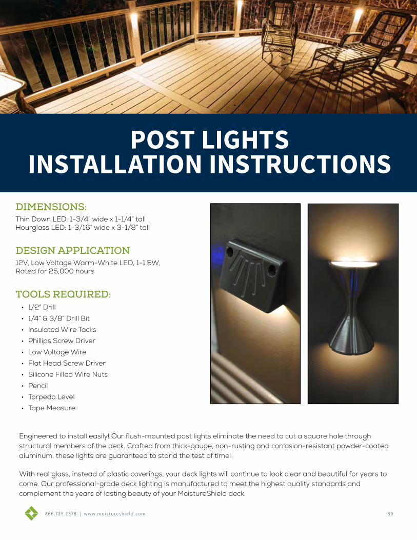
8 6 6 .7 2 9 . 2 3 7 8 | w w w. m o i s t u r e s h i e l d . c o m 3 9
POST LIGHTSINSTALLATION INSTRUCTIONS
DIMENSIONS:Thin Down LED: 1-3/4” wide x 1-1/4” tallHourglass LED: 1-3/16” wide x 3-1/8” tall
TOOLS REQUIRED:• 1/2” Drill
• 1/4” & 3/8” Drill Bit
• Insulated Wire Tacks
• Phillips Screw Driver
• Low Voltage Wire
• Flat Head Screw Driver
• Silicone Filled Wire Nuts
• Pencil
• Torpedo Level
• Tape Measure
Engineered to install easily! Our flush-mounted post lights eliminate the need to cut a square hole through structural members of the deck. Crafted from thick-gauge, non-rusting and corrosion-resistant powder-coated aluminum, these lights are guaranteed to stand the test of time!
With real glass, instead of plastic coverings, your deck lights will continue to look clear and beautiful for years to come. Our professional-grade deck lighting is manufactured to meet the highest quality standards and complement the years of lasting beauty of your MoistureShield deck.
DESIGN APPLICATION12V, Low Voltage Warm-White LED, 1-1.5W, Rated for 25,000 hours
POST LIGHTS INSTALLATION INSTRUCTIONS
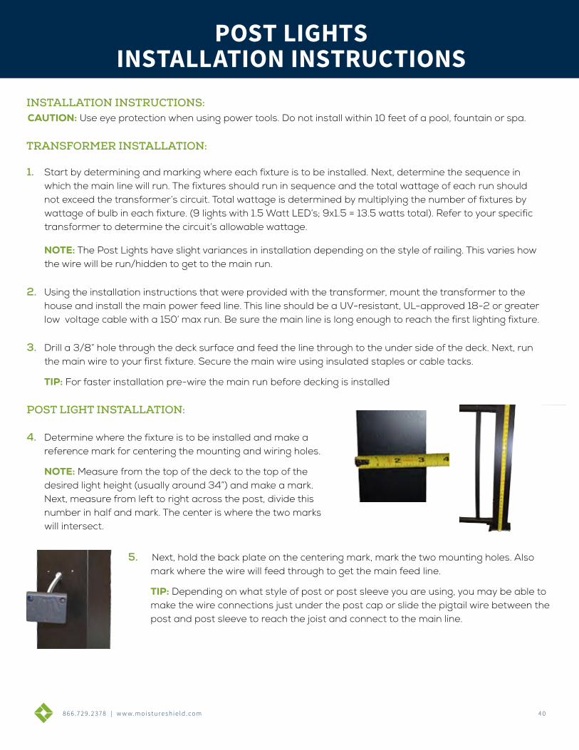
8 6 6 .7 2 9 . 2 3 7 8 | w w w. m o i s t u r e s h i e l d . c o m 4 0
DECK CLIP SYSTEMINSTALLATION INSTRUCTIONS
COMPLETE SYSTEMCOVERS 50 SQUARE FEET OF DECKING
• 5 starter clips
• 5 finish clips
• 90 clips
• 90 screws or 90 pneumatic fasteners
DECK/CONTRACTOR PACKCOVERS 250 SQUARE FEET OF DECKING
• 450 clips
• 500 screws (Deck Pack) or 500 pneumatic fasteners (Contractor Pack) *Does not include starter or finish clips
866.729.2378 | WWW.MOISTURESHIELD.COM
BENEFITS:• Easiest clip to install with square drive ACQ compatible screws or pneumatic fasteners
• Concealed deck clips allow for an unblemished deck surface
• Base of clip elevates board off the joists, reducing rot, mold, ice shear and lateral load stress
• Automatically spaces the deck boards 3/16” for a uniform appearance
• Limited Lifetime Warranty against loose deck boards
• Available in high strength steel with a patented coating process to resist corrosion or 304 grade stainless steel for coastal applications
• Approved for ACQ joists and all other PT joists
*All clips available in stainless steel
POST LIGHTSINSTALLATION INSTRUCTIONS
CAUTION: Use eye protection when using power tools. Do not install within 10 feet of a pool, fountain or spa.
1. Start by determining and marking where each fixture is to be installed. Next, determine the sequence in which the main line will run. The fixtures should run in sequence and the total wattage of each run should not exceed the transformer’s circuit. Total wattage is determined by multiplying the number of fixtures by wattage of bulb in each fixture. (9 lights with 1.5 Watt LED’s; 9x1.5 = 13.5 watts total). Refer to your specific transformer to determine the circuit’s allowable wattage.
NOTE: The Post Lights have slight variances in installation depending on the style of railing. This varies how the wire will be run/hidden to get to the main run.
2. Using the installation instructions that were provided with the transformer, mount the transformer to the house and install the main power feed line. This line should be a UV-resistant, UL-approved 18-2 or greater low voltage cable with a 150’ max run. Be sure the main line is long enough to reach the first lighting fixture.
3. Drill a 3/8” hole through the deck surface and feed the line through to the under side of the deck. Next, run the main wire to your first fixture. Secure the main wire using insulated staples or cable tacks.
TIP: For faster installation pre-wire the main run before decking is installed
POST LIGHT INSTALLATION:
4. Determine where the fixture is to be installed and make a reference mark for centering the mounting and wiring holes.
NOTE: Measure from the top of the deck to the top of the desired light height (usually around 34”) and make a mark. Next, measure from left to right across the post, divide this number in half and mark. The center is where the two marks will intersect.
5. Next, hold the back plate on the centering mark, mark the two mounting holes. Also mark where the wire will feed through to get the main feed line.
TIP: Depending on what style of post or post sleeve you are using, you may be able to make the wire connections just under the post cap or slide the pigtail wire between the post and post sleeve to reach the joist and connect to the main line.
INSTALLATION INSTRUCTIONS:
TRANSFORMER INSTALLATION:
POST LIGHTS INSTALLATION INSTRUCTIONS
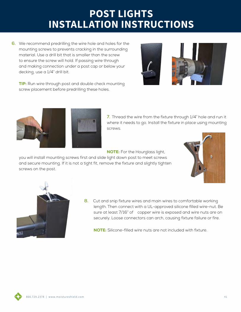
8 6 6 .7 2 9 . 2 3 7 8 | w w w. m o i s t u r e s h i e l d . c o m 41
DECK CLIP SYSTEMINSTALLATION INSTRUCTIONS
COMPLETE SYSTEMCOVERS 50 SQUARE FEET OF DECKING
• 5 starter clips
• 5 finish clips
• 90 clips
• 90 screws or 90 pneumatic fasteners
DECK/CONTRACTOR PACKCOVERS 250 SQUARE FEET OF DECKING
• 450 clips
• 500 screws (Deck Pack) or 500 pneumatic fasteners (Contractor Pack) *Does not include starter or finish clips
866.729.2378 | WWW.MOISTURESHIELD.COM
BENEFITS:• Easiest clip to install with square drive ACQ compatible screws or pneumatic fasteners
• Concealed deck clips allow for an unblemished deck surface
• Base of clip elevates board off the joists, reducing rot, mold, ice shear and lateral load stress
• Automatically spaces the deck boards 3/16” for a uniform appearance
• Limited Lifetime Warranty against loose deck boards
• Available in high strength steel with a patented coating process to resist corrosion or 304 grade stainless steel for coastal applications
• Approved for ACQ joists and all other PT joists
*All clips available in stainless steel
POST LIGHTSINSTALLATION INSTRUCTIONS
6. We recommend predrilling the wire hole and holes for the mounting screws to prevents cracking in the surrounding material. Use a drill bit that is smaller than the screw to ensure the screw will hold. If passing wire through and making connection under a post cap or below your decking, use a 1/4” drill bit.
TIP: Run wire through post and double check mounting screw placement before predrilling these holes.
7. Thread the wire from the fixture through 1/4” hole and run it where it needs to go. Install the fixture in place using mounting screws.
NOTE: For the Hourglass light, you will install mounting screws first and slide light down post to meet screws and secure mounting. If it is not a tight fit, remove the fixture and slightly tighten screws on the post.
8. Cut and snip fixture wires and main wires to comfortable working length. Then connect with a UL-approved silicone filled wire-nut. Be sure at least 7/16” of copper wire is exposed and wire nuts are on securely. Loose connectors can arch, causing fixture failure or fire.
NOTE: Silicone-filled wire nuts are not included with fixture.
POST LIGHTS INSTALLATION INSTRUCTIONS
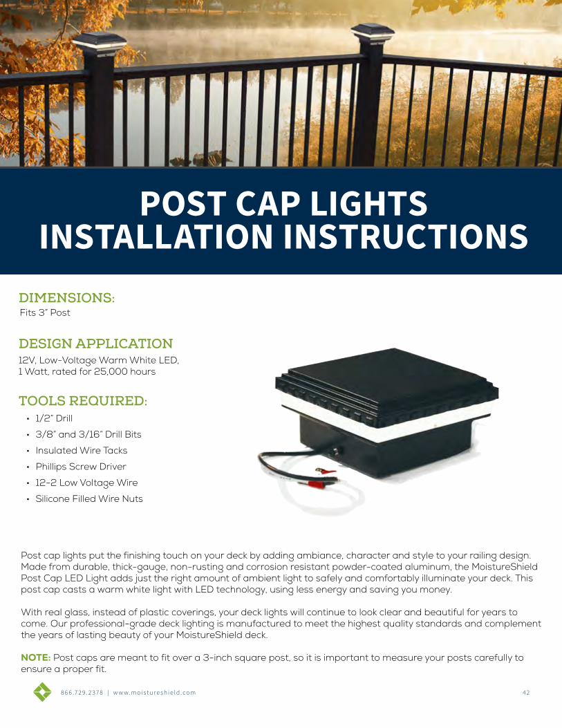
8 6 6 .7 2 9 . 2 3 7 8 | w w w. m o i s t u r e s h i e l d . c o m 42
POST CAP LIGHTSINSTALLATION INSTRUCTIONS
DIMENSIONS:Fits 3” Post
TOOLS REQUIRED:• 1/2” Drill
• 3/8” and 3/16” Drill Bits
• Insulated Wire Tacks
• Phillips Screw Driver
• 12-2 Low Voltage Wire
• Silicone Filled Wire Nuts
DESIGN APPLICATION12V, Low-Voltage Warm White LED, 1 Watt, rated for 25,000 hours
Post cap lights put the finishing touch on your deck by adding ambiance, character and style to your railing design. Made from durable, thick-gauge, non-rusting and corrosion resistant powder-coated aluminum, the MoistureShield Post Cap LED Light adds just the right amount of ambient light to safely and comfortably illuminate your deck. This post cap casts a warm white light with LED technology, using less energy and saving you money.
With real glass, instead of plastic coverings, your deck lights will continue to look clear and beautiful for years to come. Our professional-grade deck lighting is manufactured to meet the highest quality standards and complement the years of lasting beauty of your MoistureShield deck.
NOTE: Post caps are meant to fit over a 3-inch square post, so it is important to measure your posts carefully to ensure a proper fit.
POST CAP LIGHTS INSTALLATION INSTRUCTIONS
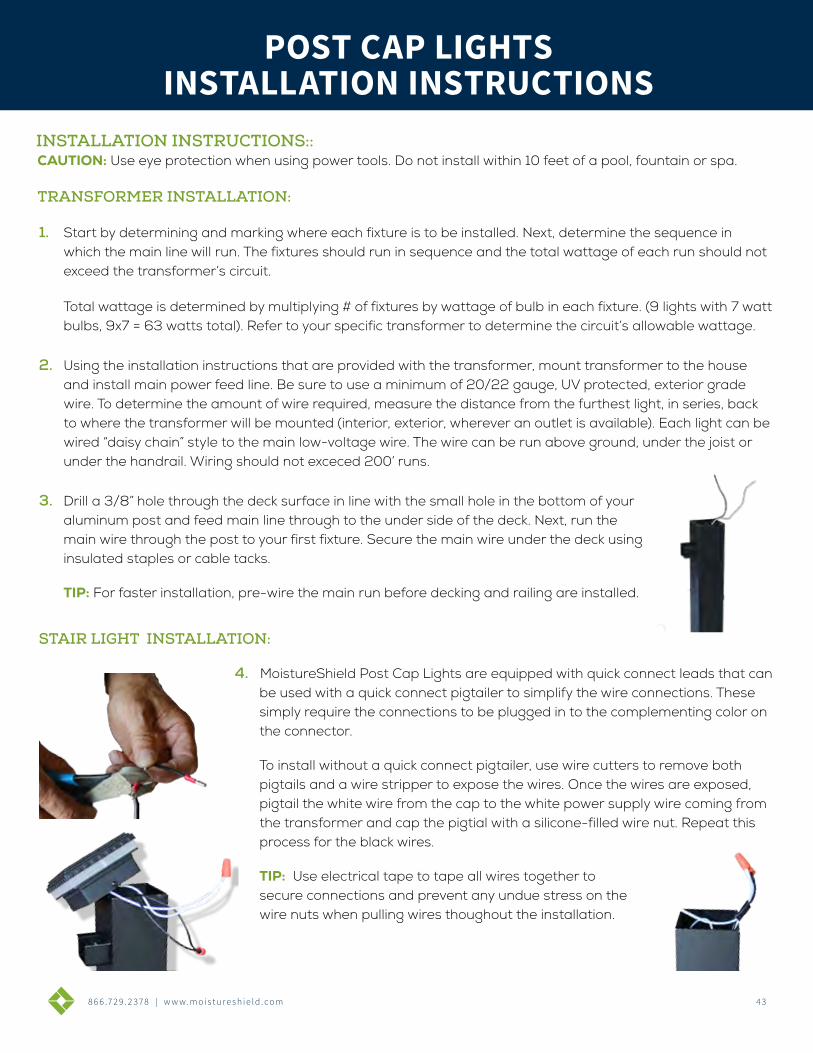
8 6 6 .7 2 9 . 2 3 7 8 | w w w. m o i s t u r e s h i e l d . c o m 4 3
DECK CLIP SYSTEMINSTALLATION INSTRUCTIONS
COMPLETE SYSTEMCOVERS 50 SQUARE FEET OF DECKING
• 5 starter clips
• 5 finish clips
• 90 clips
• 90 screws or 90 pneumatic fasteners
DECK/CONTRACTOR PACKCOVERS 250 SQUARE FEET OF DECKING
• 450 clips
• 500 screws (Deck Pack) or 500 pneumatic fasteners (Contractor Pack) *Does not include starter or finish clips
866.729.2378 | WWW.MOISTURESHIELD.COM
BENEFITS:• Easiest clip to install with square drive ACQ compatible screws or pneumatic fasteners
• Concealed deck clips allow for an unblemished deck surface
• Base of clip elevates board off the joists, reducing rot, mold, ice shear and lateral load stress
• Automatically spaces the deck boards 3/16” for a uniform appearance
• Limited Lifetime Warranty against loose deck boards
• Available in high strength steel with a patented coating process to resist corrosion or 304 grade stainless steel for coastal applications
• Approved for ACQ joists and all other PT joists
*All clips available in stainless steel
INSTALLATION INSTRUCTIONS
CAUTION: Use eye protection when using power tools. Do not install within 10 feet of a pool, fountain or spa.
1. Start by determining and marking where each fixture is to be installed. Next, determine the sequence in which the main line will run. The fixtures should run in sequence and the total wattage of each run should not exceed the transformer’s circuit.
Total wattage is determined by multiplying # of fixtures by wattage of bulb in each fixture. (9 lights with 7 watt bulbs, 9x7 = 63 watts total). Refer to your specific transformer to determine the circuit’s allowable wattage.
2. Using the installation instructions that are provided with the transformer, mount transformer to the house and install main power feed line. Be sure to use a minimum of 20/22 gauge, UV protected, exterior grade wire. To determine the amount of wire required, measure the distance from the furthest light, in series, back to where the transformer will be mounted (interior, exterior, wherever an outlet is available). Each light can be wired “daisy chain” style to the main low-voltage wire. The wire can be run above ground, under the joist or under the handrail. Wiring should not exceced 200’ runs.
3. Drill a 3/8” hole through the deck surface in line with the small hole in the bottom of your aluminum post and feed main line through to the under side of the deck. Next, run the main wire through the post to your first fixture. Secure the main wire under the deck using insulated staples or cable tacks.
TIP: For faster installation, pre-wire the main run before decking and railing are installed.
STAIR LIGHT INSTALLATION:
4. MoistureShield Post Cap Lights are equipped with quick connect leads that can be used with a quick connect pigtailer to simplify the wire connections. These simply require the connections to be plugged in to the complementing color on the connector.
To install without a quick connect pigtailer, use wire cutters to remove both pigtails and a wire stripper to expose the wires. Once the wires are exposed, pigtail the white wire from the cap to the white power supply wire coming from the transformer and cap the pigtial with a silicone-filled wire nut. Repeat this process for the black wires.
TIP: Use electrical tape to tape all wires together to secure connections and prevent any undue stress on the wire nuts when pulling wires thoughout the installation.
INSTALLATION INSTRUCTIONS::
POST CAP LIGHTS
TRANSFORMER INSTALLATION:
POST CAP LIGHTS INSTALLATION INSTRUCTIONS
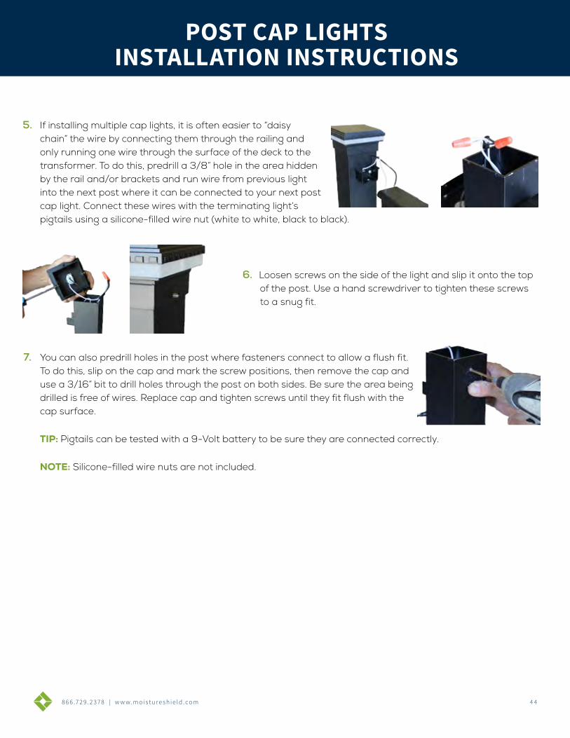
8 6 6 .7 2 9 . 2 3 7 8 | w w w. m o i s t u r e s h i e l d . c o m 4 4
DECK CLIP SYSTEMINSTALLATION INSTRUCTIONS
COMPLETE SYSTEMCOVERS 50 SQUARE FEET OF DECKING
• 5 starter clips
• 5 finish clips
• 90 clips
• 90 screws or 90 pneumatic fasteners
DECK/CONTRACTOR PACKCOVERS 250 SQUARE FEET OF DECKING
• 450 clips
• 500 screws (Deck Pack) or 500 pneumatic fasteners (Contractor Pack) *Does not include starter or finish clips
866.729.2378 | WWW.MOISTURESHIELD.COM
BENEFITS:• Easiest clip to install with square drive ACQ compatible screws or pneumatic fasteners
• Concealed deck clips allow for an unblemished deck surface
• Base of clip elevates board off the joists, reducing rot, mold, ice shear and lateral load stress
• Automatically spaces the deck boards 3/16” for a uniform appearance
• Limited Lifetime Warranty against loose deck boards
• Available in high strength steel with a patented coating process to resist corrosion or 304 grade stainless steel for coastal applications
• Approved for ACQ joists and all other PT joists
*All clips available in stainless steel
INSTALLATION INSTRUCTIONS
5. If installing multiple cap lights, it is often easier to “daisy chain” the wire by connecting them through the railing and only running one wire through the surface of the deck to the transformer. To do this, predrill a 3/8” hole in the area hidden by the rail and/or brackets and run wire from previous light into the next post where it can be connected to your next post cap light. Connect these wires with the terminating light’s pigtails using a silicone-filled wire nut (white to white, black to black).
6. Loosen screws on the side of the light and slip it onto the top of the post. Use a hand screwdriver to tighten these screws to a snug fit.
7. You can also predrill holes in the post where fasteners connect to allow a flush fit. To do this, slip on the cap and mark the screw positions, then remove the cap and use a 3/16” bit to drill holes through the post on both sides. Be sure the area being drilled is free of wires. Replace cap and tighten screws until they fit flush with the cap surface.
TIP: Pigtails can be tested with a 9-Volt battery to be sure they are connected correctly.
NOTE: Silicone-filled wire nuts are not included.
POST CAP LIGHTSPOST CAP LIGHTS
INSTALLATION INSTRUCTIONS

AERT19-758 © 2020 MoistureShield® is part of the Architectural Products Group of Oldcastle® APG, Inc.
MOIS TUR E S HIELD.COM