installation, care and maintenance - tadmur trading description introduction thank you for buying an...
TRANSCRIPT

Self-priming centrifugal pumps
Installation, Care and Maintenance

CONTENTS
Safety ................................................................ 2Warranty ............................................................ 4Product description .......................................... 4Transportation and storage ............................. 5Installation ........................................................ 5Operation .......................................................... 7
Care and Maintenance..................................... 9Inspection .......................................................... 9Replacing worn-out parts ............................... 10Fault tracing ................................................... 13Service log ...................................................... 14
SAFETY
This manual contains basic information on theinstallation, operation and maintenance and shouldbe followed carefully. It is essential that theseinstructions are carefully read before installation orcommissioning by both the installation crew aswell as those responsible for operation ormaintenance. The operating instructions shouldalways be readily available at the location of theunit.
This manual provides general informationconcerning the pumping unit but does notinclude detailed instructions for the driveunits (diesel or electric motor); theseinstructions can be found on the specificmanuals which must be provided with thismanual and form an integral part of it.
Identification of safety and warning symbols
General Danger:Non-observance given to safetyinstructions in this manual,which could cause danger tolife have been speficallyhighlighted with this generaldanger symbol.
WARNING ! Non-observance to this warningcould damage the unit or affectits function
Qualifications of personnelAll activities must be carried out by authorized(certified) instructed personnel.
Safety regulations for the owner/operator
All safety and hygiene rules andlocal regulations must beobserved.
All dangers related tomechanical equipment andmoving parts must be avoided.
WARNING! Follow all the warning labelsfixed on the unit
When operating near thepumping unit, avoid wearingloose-fitting clothes, or otherthings that could get caught (likearmlet, chains, etc.) and gatherany long hair.
Periodically check the presenceand readability of the warninglabels.
Check the presence, correctfixing and perfect condition of thefixed protections applied.
When the machine is running, donot put anything into the pumpthrough the inlet/outlet or fromthe inspection cover as there isthe risk of contact with movingparts (impeller).
In order to avoid danger to thepersonnel operating near thepumping unit, check correctconnection and tightening of theinlet/outlet before starting up.
2

The pumping unit must not beused in places where there is thedanger of explosion and/or fire,in mines and tunnels and inplaces with poor ventilationunless special precautions aretaken by the user.
The pumping unit must neverbe used to treat liquidsintended for human or animalconsumption (alimentary use).
The pumping unit is providedwith a bolt for earth connectionto ensure equipotentiality andprevent static electricity.
The pumping unit must beinstalled in a workplace withsufficient lighting for the task tobe performed; the lighting mustpermit correct identification ofthe controls and optical signalson machine board in addition toperformance of the cleaning,adjustment and maintenanceoperations and topping up ofliquids.
The pumping units equipped withdiesel engine and/or with vacuumpump are provided with oil ventpipes. Suitable devices must beprovided to prevent dispersion inthe ground.
Unilateral modification and spare partsmanufacturing
Modifications or changes to theunit/installation should only becarried out after consulting ITTFlygt.
Original spare parts andaccessories authorized by themanufacturer are essential forcompliance.
The use of other parts caninvalidate any claims forwarranty or compensation.
WARNING!
Dismantiling and re-assembly
If the pump has been used topump hazardous media, caremust be taken that, whendraining the leakage, personneland environment are notendangered.
All waste and emissions suchas used oil must beappropriately disposed of. Oilspills must be cleaned up andemissions to the environmentmust be reported.
The working area must be keptin good order at all times.
All government regulationsshall be observed.
WARNING!
3

PRODUCT DESCRIPTION
IntroductionThank you for buying an ITT Flygt pump.In this Installation Care and Maintenance manualyou will find general information on how to installand service the pumping unit to give it a long andreliable life.
Applications
The pumping unit is intended to be used for:
- pumping of ground water- lowering the groundwater level with Wellpoint
system (only for version with vacuum pump)- pumping of raw or clean water- pumping heavy, abrasive or saline liquids- drainage- dewatering- water supply from wells and canals (only for
non-alimentary uses)- pumping of liquids and mud with solid parts in
suspension (within the limits of the technicalspecifications)
- transfer of bentonite slurry
WARRANTY
ITT Flygt undertakes to remedy faults in productssold by ITT Flygt provided:
- that the fault is due to defects in design, materialsor workmanship.
- that the faults are reported to ITT Flygt or ITT Flygt’srepresentative during the warranty period.
- that the product is used only under conditiondescribed in the Installation, Care and Maintenancemanual and in applications for which it is intended
- that the monitoring equipment incorporated in theproduct is correctly connected and in use.
- that all service and repair work is done by a workshop ITT Flygt
- that genuine ITT Flygt parts are used.
Hence, the warranty does not cover faults causedby deficient maintenance, improper installation,incorrectly executed repair work or normal wear andtear.
ITT Flygt assumes no liability for either bodily injuries,material damages or economic losses beyond whatis stated above.
ITT Flygt guarantees that spare parts will be kept for10 years after that the manufacture of this producthas been discontinued
For further information on applications, contactyour nearest ITT Flygt representative.
Liquid temperature : max. 70 °C.
Liquid density : max. 1100 kg/m3
The pH of the pumped liquid : 5,5 – 9
4
INSTALLATION
The pumping unit may be transported and stored ina horizontal position.
Always lift the pumping unitby its lifting system; neveruse the delivery or suctionpipe or the hooks on thepump and/or on motor unit.
WARNING! Make sure thatthe pump cannot roll or fallover and injure people ordamage property
During towing in the site,check that the tow bar is fixedby means of the stop pin andthat the latter is locked throughthe locking device.
Although fitted on wheels, thepumping unit is not approvedfor use on roads.Towing is therefore forbiddenon public roads.On specific request, thepumping unit can be fitted on atrolley approved for road use.
During handling on site, ensurethat the diesel tank (fitted onpumping unit base stand) is notsubjected to impact or abrasionwhich can cause fuel leakage.
The pump is frost-proof as long as it is operating. Ifthe pump doesn’t work when the temperature is belowthe freezing point, the water freezes and the pumphousing can break.
Never leave the water in the priming chamber if thereis the risk of freezing: empty the pump through theinspection cover.
For longer periods of storage, the pump must beprotected against moisture and heat.
After a long period of storage, the pump should beinspected before it is put into operation. Pay specialattention to the shaft seal and the drive unit.
Follow the instructions under the heading “Beforestarting” in the chapter “Operation”.
TRANSPORTATION AND STORAGE
WARNING!
Handling equipment
Always pay extra attention tosafety aspects when workingwith lifting equipment.
Suitable lifting equipment isrequired for handling the pump.The lifting equipment shall beable to hoist the pumping unitstraight up and down preferablywithout the need for resetting thelifting hook.
Oversize lifting equipment couldcause damage if the pumpshould stick when being lifted.Make sure that the lift ingequipment is securely anchoredand in good condition.
Check that the lifting system isin good condition.
- Stay clear of suspendedloads
- Always lift the pump by itslifting handle
In order to guarantee adequatestability of the pumping unit andprevent it from accidentallymoving during operation, it mustbe installed in a flat positionlongitudinally and with amaximum gradient of 10%crosswise. You should thereforeavoid positioning it on steepground.
5
WARNING!
Put the pump in a horizontalposition. The suction pipe mustbe the straightest possible. It’sfree end , at a distance of, atleast, twice the diameter fromthe bottom of the excavation, isattached to a strainer to avoid thesuction of materials which coulddamage the pump.
Safety precautions
In order to minimize the risk of accidents inconnection with service and installation work, thefollowing rules should be followed :
1. Never work alone. Use a lifting harness, safetyline and a respirator as required. Do no ignorethe risk of drowning.
2. Make sure there are no dangerous gases withinthe work area.
3. Check the explosion risk before welding or usingelectric hand tools.
4. Before the pump is installed check that all theparts have not been damaged during thetransportation.
5. Observe strict cleanliness. Do not ignore healthhazards.
6. Bear in mind the risk of mechanical accidents.7. Make sure that the lifting equipment is in good
condition and comply to local ordinances.8. Provide a suitable barrier around the work area,
eg. a guard rail.9. Make sure you have a clear path of retreat.10.Use safety helmet, safety goggles and protective
shoes.11. A first-aid kit must be close at hand.
Follow all health and safety rules and local codesand ordinances.
Pumping units with diesel engine
The pumping unit must be installed in adequatelyventilated environments in order to provide sufficientair for combustion and dissipation of the heatgenerated.
If the pumping unit providedwith diesel engine is installedin a closed place, the exhaustgases must be conveyed tothe outside. The pumping unitmust be installed at least at adistance of 4 meters fromcombustible and flammablematerials or from pressurisedcontainers.
Pumping unit with electric motor
The user must protect theelectrical power supply lineand the pumping unit againstshort circuits and overloads byconnecting an adequatethermal magnetic circuitbreaker.
In order to avoid the risk of electrocution due todirect or indirect contacts with energized partsthe user must protect the pumping unit fromdirect and indirect contacts, in compliance withcurrent regulations, taking account of theambient utilisation conditions that increaseelectrical risks (e.g. differential circuit-breakerIdn ≤≤≤≤≤ 30 mA on building sites); in particular thepumping unit must not be positioned insidenarrow conducting environments, i.e. with goodearth connection (e.g. damp or wetunderground site or walls of a narrowexcavation) and reduced volume.
Damage to the power supply cable and housingcan involve contact with energized parts andlife risk;
before starting:
− Check the power cable and the control panelcondition.
− Check that the power cable size is right andit’s protected against mechanical damage.
− If the power cable or unit is damaged, donot operate!
− Replace the damaged power cable with anew one.
− Use plugs with suitable protection ratingaccording to the environment where the unitis operating (min. IP 55).
Check that the direction of rotation direction isaccording to the direction indicated on theelectrical motor; if not, change the connectionof two phases (before this operation, make surethat the electrical circuit is not energized).
6

OPERATION
Before starting
Check that the visible parts of the pump andinstallation are undamaged and in good condition.
Before starting work on thepump, make sure that thepump cannot be energizedIn case of emergency, stop thepumping unit via the mushroom-head push button on the controlpanel (electrical motor) or via thelever stop system (dieselengine).
Make sure that the pumpcannot roll or fall over andinjure people or damageproperty.
In some installations thepump surface and thesurrounding liquid may behot. Bear in mind the risk ofburn injures
The noise level of 70 dBmay be exceededOn specific request thepumping unit can beprovided with soundproofenclosure.
Before starting the unit, fill the pump casing withwater up to the lid (Tab.5 a page 10).
Then make sure there are no water leakages in themechanical seal or in the suction valve.In the first case they would prevent the pump fromworking properly and they would prolong pump-priming times.
After this simple check, start the drive unit.Remember that internal combustion engines mustbe warmed up for some minutes till they reach theoptimum temperature.
Do not change or modify theengine calibration in anyway.Never operate the pumpwithout water.
Possible causes of unsuccessful pump-priming- Pump-casing without water or with a level of the
water too low.
- Air passing through suction pipe, connectors etc.
- Broken or worn-out tang of the volute (see Tab.2,part.4)
- Wrong number of drive unit revolutions.
- Broken or worn-out impeller.
7
1
2
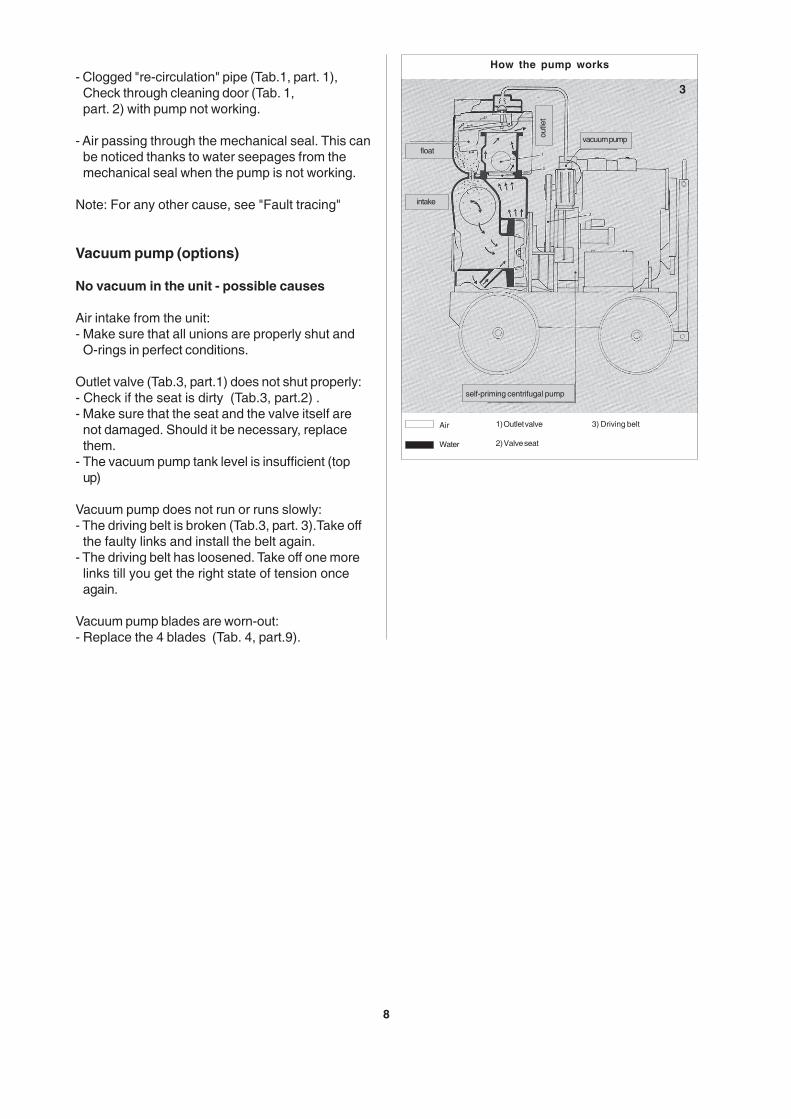
- Clogged "re-circulation" pipe (Tab.1, part. 1),Check through cleaning door (Tab. 1,part. 2) with pump not working.
- Air passing through the mechanical seal. This canbe noticed thanks to water seepages from themechanical seal when the pump is not working.
Note: For any other cause, see "Fault tracing"
Vacuum pump (options)
No vacuum in the unit - possible causes
Air intake from the unit:- Make sure that all unions are properly shut and
O-rings in perfect conditions.
Outlet valve (Tab.3, part.1) does not shut properly:- Check if the seat is dirty (Tab.3, part.2) .- Make sure that the seat and the valve itself are
not damaged. Should it be necessary, replacethem.
- The vacuum pump tank level is insufficient (topup)
Vacuum pump does not run or runs slowly:- The driving belt is broken (Tab.3, part. 3).Take off
the faulty links and install the belt again.- The driving belt has loosened. Take off one more
links till you get the right state of tension onceagain.
Vacuum pump blades are worn-out:- Replace the 4 blades (Tab. 4, part.9).
3
How the pump works
Air
Water
1) Outlet valve
2) Valve seat
3) Driving belt
vacuum pump
self-priming centrifugal pump
float
intake
outle
t
8

ITT Flygt recommends a preventive maintenanceprogram based on Intermediate and major Services atregular intervals.The time between Major Service could varyconsiderably depending on operating conditions andthe need for a Major Service will be determine duringthe regular Intermediate Services.
CARE AND MAINTENANCE
9
1) Pump casing2) Impeller3) Mechanical seal4) Pump/motor coupling box5) Vacuum pump oil tank6) Complete vacuum pump7) Outlet valve
4
8) Float to tank9) Blade10) Cock11) Oil suction filter12) Oil filter13) Air filter
For routine maintenance of the diesel engine orelectric motor, follow the instructions in the manualsprovided.
Pumping units with diesel engine
During maintenance, ensure thatno metal or other conductingobject can short-circuit thebattery terminals withconsequent danger of explosionof the battery.If you have to isolate the battery,first disconnect the negative poleand then the positive pole (thenegative pole is earthed and if thepositive pole is disconnectedfirst, it increases the risk ofaccidental short-circuit).
Pumping units with electric motor
During maintenance of thepumping unit, isolate it bydisconnecting the socket fromthe plug placed on the controlpanel.
Inspection (version with oil vacuumpump)
- Drain the condensate in the oil tank (Tab. 4,part.10), through the cock at least once a day.
- For the suction pump use SAE 15W40 ENGINEOIL.
- Every 1000 working hours wash oil suction filterwith gas/fuel oil (Tab. 4, part.11).
- Every 1000 working hours replace oil filter (Tab. 4,part.12)
- Every 1000 working hours replace air filter (Tab. 4,part.13)
Before starting work on thepump make sure that itcannot be started, evenaccidentally.

REPLACING WORN-OUT PARTS
Disassembling pump-motor coupling box (Tab 5)
Take off the pump casing by unscrewing assemblingnuts (part.4) and lever between pump and couplingbox.
The following points are important in connectionwith work on the pump.
The pump is designed for use with liquids whichcan be a health risk. In order to prevent injury to theeyes and skin, observe the following points whenworking on the pump:
WARNING! Make sure that the pump has beenthoroughly cleaned;
Beware of the risk of infection;
WARNING! Observe local safety regulations.
Always wear goggles and rubber gloves
Rinse the pump thoroughly with water before startingwork.
Rinse the components in water after dismantling.
10
5
WARNING! The oil chamber may be under pressure.Hold a rag over the filling plug to prevent splatter.
WARNING! Proceed as follows if fluid have splashedinto your eyes:
- Rinse your eyes immediately in running water for15 minutes. Hold your eyelids a part with yourfingers.
- Contact an eye specialist.
on your skin:
- Remove contaminated clothes
- Wash your skin with soap and water
- Seek medical attention, if required
Coperchio acqua
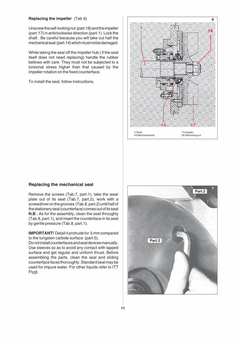
Replacing the mechanical seal
Remove the screws (Tab.7, part.1), take the wearplate out of its seat (Tab.7, part.2), work with ascrewdriver on the grooves (Tab.8, part.2) until half ofthe stationery seal (counterface) comes out of its seatN.B.: As for the assembly, clean the seat throughly(Tab.8, part.1), and insert the counterface in its seatby gentle pressure (Tab.8, part.1).
IMPORTANT! Detail 4 protrude for 5 mm comparedto the tungsten carbide surface (part.5).Do not install counterfaces and seal devices manually.Use sleeves so as to avoid any contact with lappedsurface and get regular and uniform thrust. Beforeassembling the parts, clean the seal and slidingcounterface faces thoroughly. Standard seal may beused for impure water. For other liquids refer to ITTFlygt.
11
6Replacing the impeller (Tab 6)
Unscrew the self-locking nut (part.18) and the impeller(part.17) in anticlockwise direction (part.1). Lock theshaft . Be careful because you will take out half themechanical seal (part.14) which must not be damaged.
While taking the seal off the impeller hub ( if the sealitself does not need replacing) handle the rubberbellows with care. They must not be subjected to atorsional stress higher than that caused by theimpeller rotation on the fixed counterface.
To install the seal, follow instructions.
1) Shaft14) Mechanical seal
17) Impeller18) Self-locking nut
7Part.2
Part.2

Impeller and wear plates
Check that measurements on the pump do not differgreatly from the following ones.A difference wouldimply reduced capacity and hydraulic efficienty aswell as stalling the engine because of friction on thefixed part of the pump casing.
Minimum space. (A) Tab. 9 (mm 0,3 max 1,5)Minimum space (B) Tab. 9 (mm 0,7 max 2)
12
8
9
Replacing front and rear wear plate
Remove all screws (Tab.7, part.1), pull out the wearplate (Tab.7, part.2).For reassembly, work in reverse and make sure thatseat is perfectly clean (Tab. 8, part.3).

Fault tracing should be performed with the machinein stand-by ensuring that the pumping unit cannotre-start, even accidentally.
Always make sure that there is no-one near thepump when it is started.
FAULT TRACING
Problems Cause Solution
The drive unit overheats
No pump-priming. The vacuometergives no values
No pump-priming even though thevacuometer shows sufficient vacuum
Flow interruption after temporary stopof the pump.
The pump has inadeguate capacity orstops working
A) The fan belt has loosened or isbroken.
B) Motor suction filter is clogged
A) Defective tightness of the pump orof the suction pipe.
B) The strainer is not completelysubmerged.
C) The mechanical seal is broken
A) Clogged bottom strainerB) The inner rubber coating of the pipe
has came off clogging it.
A) Water leakage in the suction pipebecause of defective retainingquality
A) Insufficient engine speedB) Clogged bottom strainerC) Clogged pump casingD) The inner rubber coating of the
suction pipe has come offE) Impeller and wear plates are
wornout
A) Tension it or replace itB) Clean it or replace itC) For any cause other than A or B
read the manual "Care andmaintenance" of the engine
A) Check the pump tightness afterdisconnecting the suction unit.Connect the pump again and checkall connections and pipes. Replaceany faulty parts
B) Put the strainer deep down into thewater
C) Replace the mechanical seal
A) Take it up and cleanB) Replace it
A) Check the mechanical sealB) Make sure that no liquid is coming
out of the suction valve
A) Increase engine speed to reach thecorrect range of revolutions
B) Clean the bottom strainerC) Clean impeller and diffusers through
the cleaning door or dismantle thepump casing
D) Replace suction pipeE) Replace the parts
13
Use the following checklist as an aid to fault tracing.It is assumed that the pump and installation havebeen carried out as instructed.
Follow local safety regulations and observerecommended safety precautions.

Most recentservice date
Pump N°. Hours of operation Remarks
SERVICE LOG
Sign.
14

Self-priming centrifugal pump 01.02.Eng.09.04