installation - cisco · for detailed instructions on opening the door, see the instal lation guide...
TRANSCRIPT

InstallationThis section provides installation instructions for wireless antennas supported on Cisco 1000 and 2000 Series Connected Grid (CGR) routers. This section contains the following:
Safety Precautions, page 27
Installation Requirements, page 28
General Installation Instructions for Mounting Antennas, page 30
When to Install or Replace Antennas, page 31
Antenna Ports, page 31
Connecting the Antenna to the CGR 1120, page 34
Connect the Antenna-to-Module Cable in the CGR 1240, page 35
Antenna and CG Module Color Codes, page 36
Cisco Lightning Arrestors, page 37
Obtaining Technical Assistance, page 39
Additional Information, page 40
Safety PrecautionsWarning: Do not locate the outdoor antenna near overhead power lines or other electric light or power circuits, or where it can come into contact with such circuits. When installing the antenna, take extreme care not to come into contact with such circuits, as they may cause serious injury or death. For proper installation and grounding of the antenna, please refer to national and local codes (for example, U.S.:NFPA 70, National Electrical Code, Article 810, Canada:Canadian Electrical Code, Section 54). Statement 1052
Each year hundreds of people are killed or injured when attempting to install an antenna. In many of these cases, the victim was aware of the danger of electrocution, but did not take adequate steps to avoid the hazard.
For your safety, and to help you achieve a good installation, please read and follow these safety precautions. They may save your life!
For your safety, read and follow these safety precautions.
If you are installing an antenna for the first time, for your own safety as well as others, seek professional assistance. Your Cisco sales representative can explain which mounting method to use for the size and type antenna you are about to install.
Before you install an antenna, contact your Cisco account representative to explain which mounting method to use for the size and type of antenna that you are about to install.
Find someone to help you—installing an antenna is often a two-person job.
27
Cisco Systems, Inc. www.cisco.com

Select your installation site with safety, as well as performance, in mind. Remember that electric power lines and phone lines look alike. For your safety, assume that any overhead line can kill you.
Contact your electric power company. Tell them your plans and ask them to come look at your proposed installation.
Plan your installation carefully and completely before you begin. Each person involved in an installation should be assigned to a specific task, and should know what to do and when to do it. One person should be in charge of the operation to issue instructions and watch for signs of trouble.
When installing your antenna, follow these guidelines:
— Do not use a metal ladder.
— Do not work on a wet or windy day.
— Do dress properly—wear shoes with rubber soles and heels, rubber gloves, and a long-sleeved shirt or jacket.
If the assembly starts to drop, move away from it and let it fall. Because the antenna, mast, cable, and metal guy wires are all excellent conductors of electrical current, even the slightest touch of any of these parts to a power line completes an electrical path through the antenna and the installer.
If any part of the antenna system should come in contact with a power line, do not touch it or try to remove it yourself. Call your local power company to have it removed safely.
If an accident should occur with the power lines, call for qualified emergency help immediately.
Installation RequirementsThis section contains the following:
Installation Location, page 28
Antenna Connections, page 29
Optimum Performance, page 29
Installation LocationWarning: Do not locate the outdoor antenna near overhead power lines or other electric light or power circuits, or where it can come into contact with such circuits. When installing the antenna, take extreme care not to come into contact with such circuits, as they may cause serious injury or death. For proper installation and grounding of the antenna, please refer to national and local codes (for example, U.S.:NFPA 70, National Electrical Code, Article 810, Canada:Canadian Electrical Code, Section 54). Statement 1052
The location of the antenna is important. Objects such as metal columns, walls, and so on, reduce efficiency. Best performance is achieved when antennas are mounted at the same height and in a direct line of sight with no obstructions. If this is not possible and reception is poor, you should try different mounting positions to optimize reception.
The antenna is designed to create an omnidirectional broadcast pattern. To achieve this pattern, the antenna should be mounted clear of any obstructions to the sides of the radiating element. If the mounting location is on the side of a building or on a tower, the antenna pattern is degraded on the building or tower side.
Antenna installation and replacement should only be performed at one of the following, certified location types:
Utility maintenance and repair depot
Cisco DF facility
28

Customer premises field depot
Before installing your antenna, determine the optimum location for safety and performance. Follow these steps to determine a safe distance from wires, power lines, and trees:
1. Measure the height of your antenna.
2. Add this length to the length of your tower or mast, then double this total for the minimum safe clearance distance from wires, power lines, and trees.
Caution: If you are unable to maintain this safe distance, stop and get professional technical assistance for a mounting alternative.
Antenna ConnectionsBefore you install or replace antennas, make sure the router is:
Powered off
Disconnected from all power sources
Disconnected from the Field Area Network (FAN)
Removed from a pole-top installation
Note: Caps on the N-connectors are installed on the CGR 1240 antenna ports to protect them from the environment. They must only be removed to install the integrated antenna or the antenna RF cable.
Optimum PerformanceThe higher your antenna is above the ground, the better it performs, generally. It is good practice is to install your antenna about 5 to 10 ft (1.5 to 3 m) above the roof line and away from all power lines and obstructions. If possible, find a mounting place directly above your wireless device so that the lead-in cable can be as direct as possible.
Antennas transmit and receive radio signals which are susceptible to RF obstructions and common sources of interference that can reduce throughput and range of the device to which they are connected. Follow these guidelines to ensure the best possible performance:
Install the antenna vertically and mount it with the cables pointing towards the ground.
Keep the antenna away from metal obstructions such as heating and air-conditioning ducts, large ceiling trusses, building superstructures, and major power cabling runs. If necessary, use a rigid conduit to lower the antenna away from these obstructions.
The density of the materials used in surrounding buildings’ construction impacts antenna signal strength. Consider the following
— Signals penetrate paper and vinyl walls with little change to signal strength.
— Signals penetrate only one or two solid and pre-cast concrete walls without degrading signal strength.
— Signals penetrate three or four concrete and wood block walls without degrading signal strength.
— Signals penetrate five or six walls constructed of drywall or wood without degrading signal strength.
— Signals are likely to reflect off a thick metal wall and not penetrate it at all.
— Signals are likely to reflect off a chain link fence or a wire mesh with spaces of 1 to 1-1/2 in (2.5 to 3.8 cm).
29

Microwave ovens and 2-GHz cordless phones can cause signal interference because they operate in the same frequency range as the WiFi radio to which one of the antennas is connected.
For instructions on installing or replacing a Cisco Connected Grid module, see the corresponding installation and configuration guide for each module.
For detailed instructions on opening the door, see the installation guide of your router. Before installing the antenna according to the installation procedures in the following chapters, you must complete these steps:
— Open the router chassis door.
— Remove any plug or connector that is installed in the antenna port.
— Verify the correct antenna port for installation, based on the antenna model you are installing.
See the installation document for your router regarding the correct antenna port location. Antennas must be installed in the correct antenna port for ease of installation and optimal performance.
Note: Ensure that you are able to access the antenna port from inside the router. If an installed module prevents you from reaching the antenna port, you might have to remove the module before installing the antenna, then reinstall the module. See the corresponding module installation and configuration guide for each module.
General Installation Instructions for Mounting AntennasCaution: For outside installations, make sure you do not mount the antenna upside down or block the bottom of the antenna at the cable exit. The correct mounting position is with the cable pointing down (towards the ground) so that any moisture will drain through the antenna drain holes. The antenna ships with a yellow mounting instruction label temporarily attached to the antenna radome.
The following instructions are common to most mast mounted installations.
1. Assemble your new antenna on the ground or a level surface at the installation site.
2. Connect its coaxial cable while you are on the ground and attach the antenna to the mast.
3. Ensure that the mast does not fall as you raise or remove it. Use a durable non-conductive rope secured at each two foot level as the mast is raised. Have an assistant tend the rope, ready to pull the mast clear of any hazards (such as power lines) should it begin to fall.
4. Use the mounting bracket provided with the antenna.
5. If the installation will use guy wires:
a. Install guy anchor bolts.
b. Estimate the length of guy wire and cut it before raising the mast.
c. Attach guy wires to a mast using guy rings.
6. Carefully connect the antenna and mast assembly to its mounting bracket and tighten the clamp bolts.
In the case of a a guyed (tall, thin mast) installation, you must have at least one assistant to hold the mast upright while the guy wires are attached and tightened to the anchor bolts.
7. Attach a “DANGER” label at eye level on the mast.
8. Install ground rods to remove any static electricity buildup and connect a ground wire to the mast and ground rod. Use ground rods designed for that purpose, not a spare piece of pipe.
30

When to Install or Replace AntennasDepending on the router configuration, it could arrive in the shipping container with all required antennas already installed and connected to the corresponding Cisco Connected Grid moduless (CG) that inside the router.
However, you might need to install an antenna on the router when:
You purchase a CG Module separately from the router. The antenna is included in the module kit, and must be installed on the router to complete the module installation procedure.
You purchase an antenna separately to replace a faulty or damaged antenna.
Antenna PortsThis section describes the antenna ports, their locations on the router, and the recommended antenna installation locations. This section includes the following topics:
Antenna Port Numbering, page 31
Unused Antenna Ports-N Connectors, page 33
Antenna Port NumberingThis section illustrates the antenna port locations on the router. Each antenna port is numbered. The antenna port numbers can be referenced by installers, support technicians, and other end users when installing, replacing, or troubleshooting the antennas.
Caution: Any Connected Grid antenna can be installed in any of the router antenna ports, however, Cisco recommends that antennas be installed in the locations recommended in the Cisco Connected Grid Antennas Installation Guide. Doing so ensures correct antenna cable management, ease of installation, and optimal antenna performance.
The recommended location for each antenna depends on several factors, including:
The type and number of Connected Grid modules installed in the router
The type and number of antennas required to support the installed modules
Note: The router integrated WiFi antenna is always installed in Port 5, and should not be removed or replaced with another antenna model.
Cisco CGR 1120 antenna ports are shown in Figure 1:
31

Figure 1 CGR 1120 Antenna Ports
Cisco CGR 1240 antenna ports are shown in Figure 2:
Figure 2 CGR 1240 Antenna Port Numbers (Top of Router)
3006
32
1 2
1 WiFi antenna connector 2 GPS antenna connector
1 ---
2 ---
3 3G auxiliary antenna
4 3G main antenna
Front of Router (Door)
3006
33
32
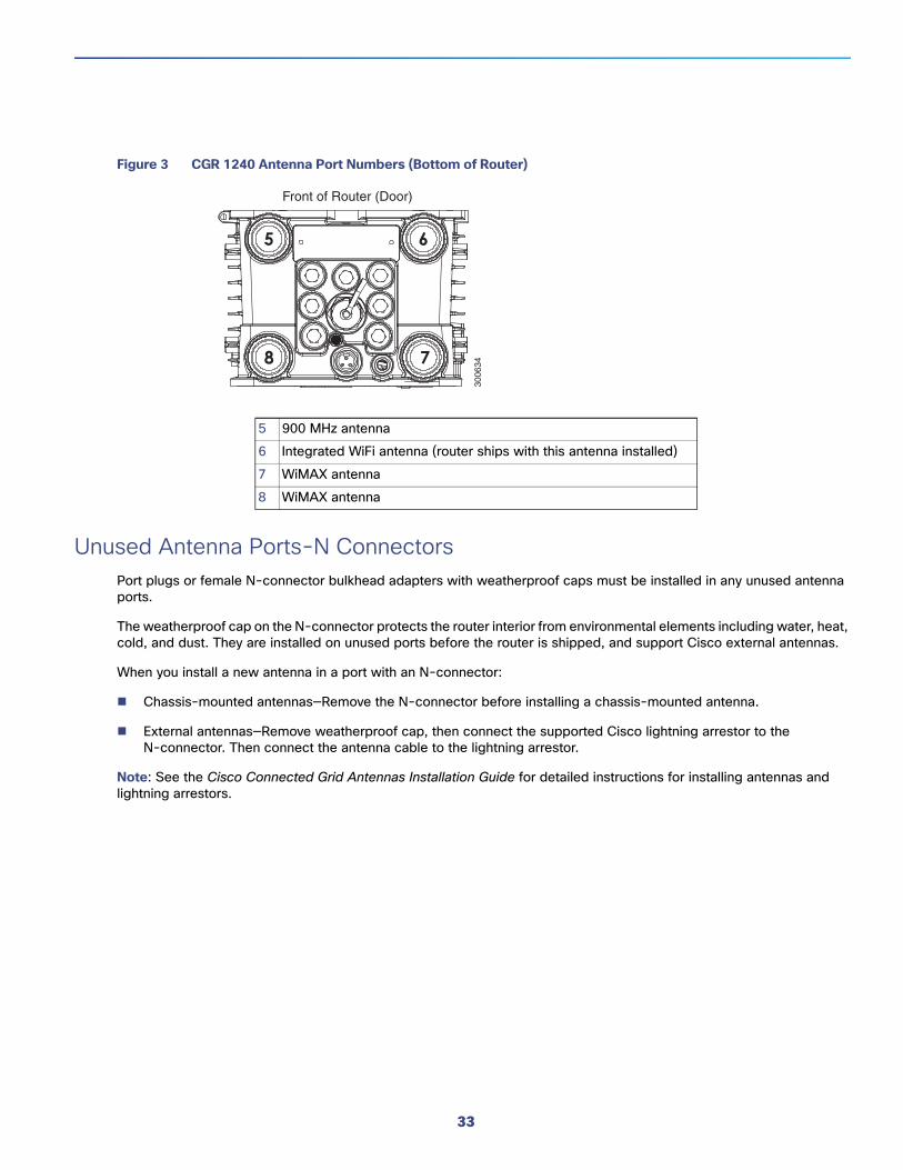
Figure 3 CGR 1240 Antenna Port Numbers (Bottom of Router)
Unused Antenna Ports-N ConnectorsPort plugs or female N-connector bulkhead adapters with weatherproof caps must be installed in any unused antenna ports.
The weatherproof cap on the N-connector protects the router interior from environmental elements including water, heat, cold, and dust. They are installed on unused ports before the router is shipped, and support Cisco external antennas.
When you install a new antenna in a port with an N-connector:
Chassis-mounted antennas—Remove the N-connector before installing a chassis-mounted antenna.
External antennas—Remove weatherproof cap, then connect the supported Cisco lightning arrestor to the N-connector. Then connect the antenna cable to the lightning arrestor.
Note: See the Cisco Connected Grid Antennas Installation Guide for detailed instructions for installing antennas and lightning arrestors.
5 900 MHz antenna
6 Integrated WiFi antenna (router ships with this antenna installed)
7 WiMAX antenna
8 WiMAX antenna
Front of Router (Door)
3006
34
33

Figure 4 N-Connector Installed in Unused Antenna Port
Connecting the Antenna to the CGR 1120Secure the coaxial end of the end-to-end RF antenna cable to the antenna ports of your CGR 1120 router. as shown in Figure 5.
3006
64
4
2
3
1
1 Lightning arrestor 2 N-connector: torque to 6 to 7 ft-lbs
3 Plug: torque to 6 to 7 ft-lbs 4 Ports must have either an antenna, connector, or plug installed.
34

Figure 5 Insert Base of Antenna into Router Antenna Port
Connect the Antenna-to-Module Cable in the CGR 1240The antenna-to-module coaxial antenna cable (MCX to QMA connectors) is shipped with your antenna. It is used as the interface between the external cable connection to the installed module.
To install the universal coaxial cable onto the router, follow these steps:
1. Remove any plug or N-connector cap on the antenna port, if one is present.
2. Install the lightning arrestor onto the bulkhead N-connector.
3. Attach the antenna cable. Do not tighten the antenna completely—stop tightening so that the antenna is not fully installed.
4. From the chassis interior, the antenna MCX jack should be visible in the plug. With one hand, position the right-angle end of the universal coaxial cable to the antenna’s MCX jack. With your other hand, push the cable end so it inserts into the MCX jack of the antenna.
3006
32
1 2
1 WiFi antenna connector 2 GPS antenna connector
3006
38
35

5. From the exterior of the router, tighten the antenna using a strap wrench. Tighten to 6 to 7 ft-lbs.
6. From the interior of the router, install the coaxial end of the cable to the appropriate connector on your installed module. The antenna cable and module port should be the same color (red, yellow, or green). For more information, see Antenna and CG Module Color Codes, page 36.
Note: Take care in routing cables so they avoid pinching and interfering with the Battery Backup Unit (BBU) when the chassis front door is closed.
Note: Some modules require two antennas: a main antenna and a diversity antenna. These modules have two antenna connectors on the front panel, labeled MAIN and AUX. Be sure to connect the main and diversity antennas to the correct module connectors.
Antenna and CG Module Color CodesThe antennas and the Cisco Connected Grid modules are color coded to help you correctly connect the antenna cables to the CGR modules installed in the router. The antenna cable has a color at the connector end that corresponds with colored antenna cable port(s) on the supported CGR module.
Note: The color coded modules and cables apply to the integrated antennas and the 4G omnidirectional stick dipole antennas only.
When you connect the antenna cable to the CGR module, as described in the section installation procedures of your antenna, match the cable color to the module connector color.
3
3006
45
1
2
MAIN
AUX
4
1 Antenna base 2 Universal coaxial antenna cable (MCX-to-QMA-male connector)
3 Connected grid module coaxial connectors (QMA-female)
4 Universal coaxial cable, MCX end
36

Figure 6 Example — Color Coding on Antenna Cable
The monopole antenna color code information follows:
Cisco Lightning ArrestorsThis section provides an overview on how to ground your mast and antenna using the lightning arrestor. See the product documentation for your lightning arrestor for details.
Note: The lightning arrestor is not required for indoor antennas.
Cisco lightning arrestors provide a level of safety protection to the installer as well as to wireless equipment by shunting to ground over-voltage transients induced into outdoor antennas and cables. These transients, in mild cases can produce interfering signals in a wireless system, and in extreme cases, can be dangerous and destructive.
Overvoltage transients can be created through lightning static discharges, switch processes, direct contact with power lines, or through earth currents. The Cisco 3G-ACC-OUT-LA Lightning Arrestor limits the amplitude and duration of disturbing interference voltages and improves the overvoltage resistance of in-line equipment, systems, and components. A lightning arrestor installed according to these mounting instructions balances the voltage potential, thus providing safety and preventing inductive interference to parallel signal lines within the protected system.
1 Color-coded antenna base
Color Antenna Product Number Connected Grid Module
Yellow ANT-MP-INT-OUT-M, 07-1140-02
RF antenna, 900MHz, 3G, WiFi, 2.5GHz WiMAX, omnidirectional, outdoor, transit style, 806 to 960 MHz, 1710 to 2700 MHz, MCX receptacle, 3.2" high, -40 to 185 degrees F (–40 to 85 degrees C)
RF900
3G
WiMAX 1.8 MHz
WiMAX 2.3/2.5 GHz
Green ANT-4G-INT-OUT-M, 07-1141-02
RF antenna, 4G, omnidirectional, outdoor, transit style, 698-960 MHz, 1710-2700 MHz, MCX receptacle, 3.2" high, –40 to 185 degrees F (–40 to 85 degrees C)
700 MHz LTE 4G
Red ANT-WM-INT-OUT-M, 07-1142-02
RF 1.4, 3.6 GHz WiMAX, antenna, omnidirectional, outdoor, transit style, 1390 to 1435, 3300 to 3800 MHz, MCX receptacle, 3.2" high, –40 to 185 degrees F (–40 to 85 degrees C)
WiMAX 3.3 to 3.8 GHz
3006
35
1
37

Consider the following:
Find a suitable location for the arrestor near a suitable ground per the relevant Safety codes.
The arrestor should either be bulkhead grounded (preferred way) or grounded through the lug provided and 6 AWG wire no more than 20" (50.8 cm) long.
To install a lightning arrestor for the Cisco 1240 CGR (CGR-LA-NM-NF), see:
http://www.cisco.com/en/US/docs/routers/connectedgrid/lightning_arrestor/Lightning_Arrestor_for_the_Cisco_1240_Connected_Grid_Router.html
Installing the Lightning Arrestor for the CGR 1120The lightning arrestor (CGR-LA-NF-NF) is designed to be installed in series, between the antenna cable that is attached to the 3G outdoor antenna and the second antenna cable entering the building. It is recommended that the arrestor and its ground connection is made as close as possible to where it enters the building, either just outside or just inside the building.
Cisco recommends that the lightning arrestor is bulkhead-mounted and is being directly attached to a well-grounded bracket or well-grounded panel through the threaded shaft of the arrestor and the supplied nut. If this is not possible, then the next best option is to use the ground lug provided with the kit. The ground lug requires a 6-AWG copper ground wire (user provided) that is crimped onto the lug and the other end connected to a good solid ground point (for example, an electrical ground buss bar). You must keep the ground wire length as short (under 20"/50.8 cm) as possible for best results.
This section provides an overview on how to ground your mast and antenna using the lightning arrestor. See the product documentation for your lightning arrestor for details.
Warning: Do not work on the system or connect or disconnect cables during periods of lightning activity. Statement 1001
Warning: This equipment must be grounded. Never defeat the ground conductor or operate the equipment in the absence of a suitably installed ground conductor. Contact the appropriate electrical inspection authority or an electrician if you are uncertain that suitable grounding is available. Statement 1024
Warning: Only trained and qualified personnel should be allowed to install, replace, or service this equipment. Statement 1030
Warning: This warning symbol means danger. You are in a situation that could cause bodily injury. Before you work on any equipment, be aware of the hazards involved with electrical circuitry and be familiar with standard practices for preventing accidents. Use the statement number provided at the end of each warning to locate its translation in the translated safety warnings that accompanied this device. Statement 1071 SAVE THESE INSTRUCTIONS
Warning: This product is not intended to be directly connected to the Cable Distribution System. Additional regulatory compliance and legal requirements may apply for direct connection to the Cable Distribution System. This product may connect to the Cable Distribution System ONLY through a device that is approved for direct connection. Statement 1078
Warning: Before working on a system that has an on/off switch, turn OFF the power and unplug the power cord. Statement 1
Note: Find a suitable location for the lightning arrestor near a suitable ground per the relevant Safety codes.
Note: Arrestor should either be bulkhead grounded (preferred way) or grounded through the lug provided and 6 AWG wire no more than 20" (0.5 m) long.
To ground the antenna in accordance with national electrical code instructions, follow these guidelines:
1. Use No. 6 AWG copper or No. 8 or larger copper-clad steel or bronze wire as ground wires for both mast and antenna lead-in.
38

2. Securely clamp the wire to the bottom of the mast.
3. Secure the lead-in wire to a lightning arrestor and mast ground wire to the building with stand-off insulators spaced from 4 ft (1.2 m) to 8 ft (1.8 m) apart.
4. Mount the lightning arrestor as close as possible to the lead-in wire entry point on the building wall.
5. Drill a hole in the wall as close as possible to the equipment to which you will connect the lead-in cable.
Caution: There may be wires in the wall. Make sure that you determine the place you intend to drill the hole is clear of any obstructions or other hazards.
6. From inside the building, pull the cable through the hole and form a drip loop close to where it enters the building.
7. Thoroughly waterproof the lead-in area using an outdoor weather seal.
8. Install a static electricity discharge unit.
9. Connect the lead-in cable to the equipment. See the installation steps in the following chapters.
Note: Create a strain relief loop with a diameter of at least 0.75" (1.9 cm) for LMR240 cable or at least 1.75" (4.45 cm) for LMR400 cable at the cable/arrestor connection.
10. Attach the lightning arrestor.
11. Attach a second cable 25 to 50 ft (7.62 to 15.24 m) from the arrestor to the 3G-HWIC main antenna port. The total maximum length of cable recommended is 75 ft (22.86 m) for LMR-240 cable and 100 ft. (30.48 m) for LMR-400 cable in areas with good outdoor signal reception. If this is not sufficient cable length for the application, a site survey and the installer must calculate an appropriate link budget to determine the maximum cable length that can be used for the specific installation.
Obtaining Technical Assistance Cisco provides Cisco.com as a starting point for all technical assistance. Customers and partners can obtain documentation, troubleshooting tips, and sample configurations from online tools by using the Cisco Technical Assistance Center (TAC) Web Site. Cisco.com registered users have complete access to the technical support resources on the Cisco TAC Web Site.
Cisco.com is the foundation of a suite of interactive, network services that provides immediate, open access to Cisco information, networking solutions, services, programs, and resources at any time, from anywhere in the world.
Cisco.com is a highly integrated Internet application and a powerful, easy-to-use tool that provides a broad range of features and services to help you to:
Streamline business processes and improve productivity
Resolve technical issues with online support
Download and test software packages
Order Cisco learning materials and merchandise
Register for online skill assessment, training, and certification programs
You can self-register on Cisco.com to obtain customized information and service. To access Cisco.com, go to the following URL: http://www.cisco.com
39

Additional Information
Antenna InformationFor additional documentation, see the following:
For information about antennas and modules, see:
www.cisco.com/go/cg-modules
For information on omnidirectional and directional antennas, see:
http://www.cisco.com/en/US/tech/tk722/tk809/technologies_tech_note09186a00807f34d3.shtml
Cisco General Information Access the most current Cisco documentation at:
http://www.cisco.com/cisco/web/support/index.html
Access the Cisco website at:
http://www.cisco.com
Access international Cisco web sites at:
http://www.cisco.com/public/countries_languages.shtml
40