installation data - webster fuel pumps data spm single and duplex manual models spm single and...
TRANSCRIPT
70
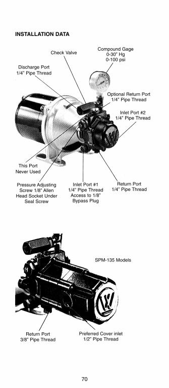
INSTALLATION DATA
Compound Gage0-30” Hg0-100 psi
Check Valve
Discharge Port1/4” Pipe Thread
This PortNever Used
Pressure AdjustingScrew 1/8” Allen
Head Socket UnderSeal Screw
SPM-135 Models
Preferred Cover inlet1/2” Pipe Thread
Return Port3/8” Pipe Thread
Optional Return Port1/4” Pipe Thread
Inlet Port #21/4” Pipe Thread
Return Port1/4” Pipe Thread
Inlet Port #11/4” Pipe ThreadAccess to 1/8”Bypass Plug
71
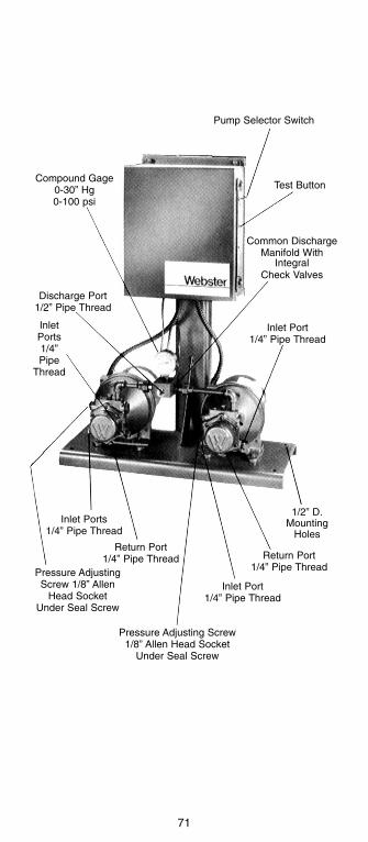
Pump Selector Switch
Test Button
Common DischargeManifold With
IntegralCheck Valves
Inlet Port1/4” Pipe Thread
Compound Gage0-30” Hg0-100 psi
Discharge Port1/2” Pipe Thread
InletPorts1/4”Pipe
Thread
Inlet Ports1/4” Pipe Thread
Return Port1/4” Pipe Thread
Inlet Port1/4” Pipe Thread
Return Port1/4” Pipe Thread
1/2” D.Mounting
Holes
Pressure AdjustingScrew 1/8” Allen
Head SocketUnder Seal Screw
Pressure Adjusting Screw1/8” Allen Head Socket
Under Seal Screw
72
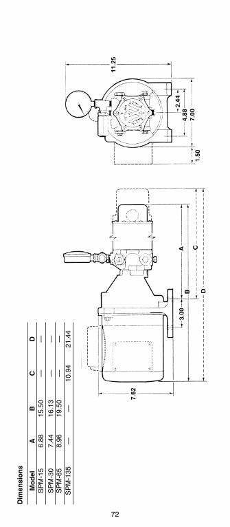
Dim
ensi
on
s
Mo
del
AB
CD
SP
M-1
56.
8815
.50
——
SP
M-3
07.
4416
.13
——
SP
M-6
58.
9619
.50
——
SP
M-1
35—
—10
.94
21.4
4

Mo
del
AP
ipe
Tap
SP
M-1
5-D
A14
.94
1/4
SP
M-3
0-D
A16
.53
1/4
SP
M-6
5-D
A16
.90
1/4
SP
M-1
35-D
A21
.37
3/8
73
Dim
ensi
on
sD
up
lex
Au
tom
atic
74
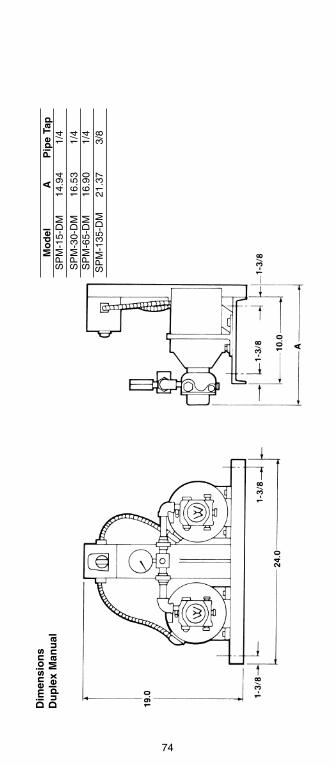
Mo
del
AP
ipe
Tap
SP
M-1
5-D
M14
.94
1/4
SP
M-3
0-D
M16
.53
1/4
SP
M-6
5-D
M16
.90
1/4
SP
M-1
35-D
M21
.37
3/8
Dim
ensi
on
sD
up
lex
Man
ual

75
INSTALLATION DATA
SPM Single and Duplex Manual Models
SPM Single and Duplex Manual units are capable of supply-ing fuel oil to heating units or tanks located up to 200 feetabove the supply pumps. They are designed for use in main-tained pressure or open loop systems. Pump pressures canbe set at a range from 20 psi to 85 psi See Correct SupplyLine Size charts, for maximum discharge head.
Tank to Pump Connections
Connect suction line from the tank to preferred supply pumpinlet port. Connect return line from pump return port to tank.Internal 1/8" bypass plug (factory installed) must be in posi-tion for recommended two-pipe operation. Be certain allplugs and connections are secure and leak tight.
The correct suction line size can be determined by referringto the charts. Generally, the return line should be sized thesame as the suction line. Check valves in the suction linesbetween the tank and SPM units assure that pumps are fullof oil, ready for service. Check valves must be oil tight. Lowpressure drop swing type are recommended to minimize fric-tion loss.
For SPM Duplex Manual models, preferred installation callsfor a separate suction line from tank to pump for eachpump/motor unit. If system failure occurs because of a grossleak in the suction line of the primary unit, the second unitcan still provide backup service. Check valves can beinstalled in return lines to allow removal of inactive pump forservicing, while primary pump continues to run.
These typical installation diagrams, illustrating a maintainedpressure supply system or optional open loop system, forcontinuous pump operation, are shown for reference only.Compliance to all applicable codes where installed is the soleresponsibility of the installer.

76
*R
equi
red
if op
tiona
l ret
urn
loop
is n
ot u
sed
+N
ot s
uppl
ied
by W
ebst
er
+
+*
+
+ +

77
SPM Duplex Automatic Models
SPM Duplex Automatic units consist of two SPM Seriespump/motor assemblies and an electrical control panel. Theyare designed for use in maintained pressure supply systemsonly. if system pressure falls below a preset level, the controlautomatically switches from the primary pump/motor unit tothe secondary unit. If the backup pump/motor unit also failsto reach or maintain preset system pressure, the control alsoshuts off the backup unit.
A pump selector switch allows the two pump/motor units tobe manually alternated for even wear on each pump. Pumppressures can be set at a range from 20 psi to 85 psi. SeeCorrect Supply Line charts, for maximum discharge head.
Tank to Pump Connections
Units should be set for two-pipe operation. Preferred instal-lation calls for a separate suction line from tank to pump foreach pump/motor unit. If system failure occurs because of agross leak in the suction line of the primary unit, the secondunit can still provide backup service.
The correct suction line size can be determined by referringto the charts Generally, the return line should be sized thesame as the suction line. Low pressure drop, swing typecheck valves can be installed in the suction lines, assuringthat pumps are full of oil, ready for service. Check valves inreturn lines allow removal of inactive pump for servicing. Useof shutoff valves in return lines is not recommended. Be cer-tain all plugs and connections are secure and leak-tight.
+ Not supplied by Webster
+ +

78
+ + +
+
+
+
*
*R
equi
red
if op
tiona
l ret
urn
loop
is n
ot u
sed
+N
ot s
uppl
ied
by W
ebst
er

79
SPM LINE SIZINGCorrect sizing of the suction and discharge lines between thestorage tank and supply unit is vital. The use of tubing or pipewhich is too small can result in restricted oil supply. The fol-lowing charts are listed to help in line sizing for supply unitinstallation.
The charts can assist in determining the suggested minimumsuction and discharge line sizes for Standard Schedule 40iron or steel pipe (IPS) and for Type K copper tubing, whichis recommended for underground service.*
To use the line sizing charts, first a supply unit must be sizedto meet the specific application. Once this has been accom-plished, the unit model number (ex. SPM-30) should be usedas a guide in referring to the correct suction and/or dischargesizing charts.
NOTE: The use of pipe or tubing which is too small cancause increased frictional losses. The result could be aninadequate system discharge pressure. Check local andstate codes pertaining to oil heating systems for any require-ments which may affect the installation and/or operation ofthe system.
The following charts apply to all SPM Single, SPM DuplexManual and SPM Duplex Automatic models. These chartsare not intended to be used in sizing pipe for any other sup-ply or transfer pump/motor units.
*Charts represent maximum horizontal run vs. vertical lift orvertical head for Standard Schedule 40 iron or steel pipe(lPS) and for Type K copper tubing, recommended for under-ground service. The actual OD and wall thickness are indi-cated for each tube size. (NOTE: The nominal size of Type Ktubing is 1/8” smaller than actual OD.)

80
RE
CO
MM
EN
DE
DS
UC
TIO
N L
INE
SIZ
ES
PM
-15

81
RE
CO
MM
EN
DE
DS
UC
TIO
N L
INE
SP
M-3
0
Suc
tion
Cha
rts
repr
esen
t m
axim
umho
rizon
tal
run
vs.
vert
ical
lif
t fo
rS
tand
ard
Sch
edul
e 40
iro
n or
ste
elpi
pe (
IPS
) an
d fo
r Ty
pe K
cop
per
tubi
ng,
reco
mm
ende
d fo
r un
der-
grou
nd s
ervi
ce.
The
act
ual
OD
and
wa
ll th
ickn
ess
a
re
ind
ica
ted
fo
rea
ch tu
be s
ize.
(N
OT
E: T
he n
omin
alsi
ze o
f Ty
pe K
tub
ing
is 1
/8”
smal
ler
than
act
ual O
D.)

RE
CO
MM
EN
DE
DS
UC
TIO
N L
INE
SIZ
ES
PM
-65
82

RE
CO
MM
EN
DE
DS
UC
TIO
N L
INE
SP
M-1
35
83
Suc
tion
Cha
rts
repr
esen
t m
axim
umho
rizon
tal
run
vs.
vert
ical
lif
t fo
rS
tand
ard
Sch
edul
e 40
iro
n or
ste
elpi
pe (
IPS
) an
d fo
r Ty
pe K
cop
per
tubi
ng,
reco
mm
ende
d fo
r un
der-
grou
nd s
ervi
ce.
The
act
ual
OD
and
wa
ll th
ickn
ess
a
re
ind
ica
ted
fo
rea
ch tu
be s
ize.
(N
OT
E: T
he n
omin
alsi
ze o
f Ty
pe K
tub
ing
is 1
/8”
smal
ler
than
act
ual O
D.)

84
RE
CO
MM
EN
DE
DD
ISC
HA
RG
E L
INE
SIZ
ES
PM
-15

85
RE
CO
MM
EN
DE
DD
ISC
HA
RG
E L
INE
SP
M-3
0
Dis
char
ge C
hart
s re
pres
ent
max
i-m
um h
oriz
onta
l ru
n vs
. ve
rtic
al l
iftfo
r S
tand
ard
Sch
edul
e 40
iro
n or
stee
l pip
e (I
PS
) an
d fo
r Ty
pe K
cop
-p
er
tub
ing
, re
com
me
nd
ed
fo
run
derg
roun
d se
rvic
e.
The
ac
tual
OD
and
wal
l thi
ckne
ss a
re in
dica
ted
for
each
tu
be
size
. (N
OT
E:
The
nom
inal
siz
e of
Typ
e K
tubi
ng is
1/8
”sm
alle
r th
an a
ctua
l OD
.)

86
RE
CO
MM
EN
DE
DD
ISC
HA
RG
E L
INE
SIZ
ES
PM
-65

87
RE
CO
MM
EN
DE
DIS
CH
AR
GE
LIN
ES
PM
-135
Dis
char
ge
Cha
rts
repr
esen
t m
axi-
mum
hor
izon
tal r
un v
s. v
ertic
al li
ft fo
rS
tand
ard
Sch
edul
e 40
iro
n or
ste
elpi
pe (
IPS
) an
d fo
r Ty
pe K
cop
per
tubi
ng,
reco
mm
ende
d fo
r un
der-
grou
nd s
ervi
ce.
The
act
ual
OD
and
wa
ll th
ickn
ess
a
re
ind
ica
ted
fo
rea
ch tu
be s
ize.
(N
OT
E: T
he n
omin
alsi
ze o
f Ty
pe K
tub
ing
is 1
/8”
smal
ler
than
act
ual O
D.)

88
RE
CO
MM
EN
DE
DD
ISC
HA
RG
E L
INE
SIZ
ES
PM
-15-
DA

89
RE
CO
MM
EN
DE
DD
ISC
HA
RG
E L
INE
SP
M-3
0-D
A
Dis
char
ge
Cha
rts
repr
esen
t m
axi-
mum
hor
izon
tal r
un v
s. v
ertic
al li
ft fo
rS
tand
ard
Sch
edul
e 40
iro
n or
ste
elpi
pe (
IPS
) an
d fo
r Ty
pe K
cop
per
tubi
ng,
reco
mm
ende
d fo
r un
der-
grou
nd s
ervi
ce.
The
act
ual
OD
and
wa
ll th
ickn
ess
a
re
ind
ica
ted
fo
rea
ch tu
be s
ize.
(N
OT
E: T
he n
omin
alsi
ze o
f Ty
pe K
tub
ing
is 1
/8”
smal
ler
than
act
ual O
D.)

90
RE
CO
MM
EN
DE
DD
ISC
HA
RG
E L
INE
SIZ
ES
PM
-65-
DA

91
RE
CO
MM
EN
DE
DD
ISC
HA
RG
E L
INE
SP
M-1
35-D
A
Dis
char
ge
Cha
rts
repr
esen
t m
axi-
mum
hor
izon
tal r
un v
s. v
ertic
al li
ft fo
rS
tand
ard
Sch
edul
e 40
iro
n or
ste
elpi
pe (
IPS
) an
d fo
r Ty
pe K
cop
per
tubi
ng,
reco
mm
ende
d fo
r un
der-
grou
nd s
ervi
ce.
The
act
ual
OD
and
wa
ll th
ickn
ess
a
re
ind
ica
ted
fo
rea
ch tu
be s
ize.
(N
OT
E: T
he n
omin
alsi
ze o
f Ty
pe K
tub
ing
is 1
/8”
smal
ler
than
act
ual O
D.)

92
The adjusting screws on the Pressuretrol, located in the fac-tory wired control panel, should be set carefully according toinstructions, below.
Setting Pump Pressure
1. Set the differential scale indicator on the pressuretrol atapproximately 5 (half-way between 10 and bottom of scale).This permanently sets the differential scale. Set main scaleindicator at 0, so supply pump can run continuously duringpurging of supply line.
2. Purge lines. Run both supply pumps to assure both are oilfilled. For priming purposes, OSV valves can be manuallyoperated by inserting a stiff wire (paper clip) through thecover hole, and depressing the diaphragm plate.
3. Pressure adjustment, pump one: Install compound gaugein tee fitting in supply line of highest or most remote burner.After starting pump one, start all burners. With all burnersoperating at maximum firing rate, adjust pump one so gaugeat remote burners, reads 20 psi.
4 Pressuretrol adjustment: With all burners firing, switch topump two and adjust pump two so gauge at last burner readsslight positive pressure (2-5 psi). Gradually increase thepressuretrol main scale setting until pump two stops, pumpone starts, and alarm buzzer sounds. Allow pump one to runand build pressure. With pump one running and pump twooff, turn pump two pressure adjusting screw about one-quar-ter turn clockwise.
5. Pressure adjustment, pump two: Move selector switch tooff momentarily, then back to pump two. Alarm will shut offand pump two will start. Adjust pump two pressure setting soit is the same as pump one (set in step three). Switch backand forth between both pumps to confirm pressure settings
DifferentialScale
AdjustingScrew
Main Scale
AdjustingScrew
Main ScaleIndicator
DifferentialScale
Indicator
SPM Duplex Automatic Controls

93
are identical. Shut off all burners. Pressure at any oil safetyvalve in system must not exceed maximum operating pres-sure of 60 psi, when supply pump is running and all burnersare off.
INSTALLATION CHECKLIST
This checklist is a general review of instructions which arevital to trouble-free operation of supply units. Each itemshould be given serious consideration during planning andinstallation of the supply system.
Problem Installation ChecklistCheck motor electrical connec-tions
Check for obstruction in return line (such as reversed check valve)
Check circuit breaker and correct possible overload
Measure suction inlet vacuum
Check that all plugs and suction lineconnections are air tight
Be certain bypass plug is inposition
Use adequate size suction line
Be certain suction line filter or strainer has adequate capacity
Install low pressure drop swing typecheck valves in suction line
Confirm specified unit can provide needed vertical discharge pressure
Check that all supply line connec-tions are air and oil tight
Use adequate size supply line
Minimize supply line restrictions
Prime pump and purge supply lines of air
Check pump pressure setting
Confirm specified unit can provide needed capacity
In pressurized system, adjust pres-sure to develop reading of 10-15 psiat most remote or highest burner
In open loop system, install stand-pipe, back pressure valve or over-sized drop pipe
Check for leaking or damaged OSVs
Supply unitdoes not run
Unit runs, butno oil reachessupply pump
Unit supplies oilto distributionsystem, but nodelivery of oil atOSV valves
Oil delivery atOSV valves, butburners do notfire

Problem Installation ChecklistCheck for line failure betweenOSVs and burner pumps
Check burner for fuel pumpfailure or ignition problems
Install OSVs to assure pressure atburner pumps does not exceed3 psi
Check to assure that pressures atOSVs do not exceed maximum of60 psi
Install pressure relief valve ifentrapment condition is detected
In multi-level systems, checkvertical distance between lowest OSV valve and highestpoint in the piping.
If you suspect mechanical failure of equipment, please con-tact your supplier.
94
Oil delivery atOSV valves, butburners do notfire (Cont.)
Burner pumpseal damage