installation guide for broan erv100s and erv100sp · installation work and electrical wiring must...
TRANSCRIPT
*This product earned the ENERGY STAR® by meeting strict energy efficiency guidelines set by Natural Resources Canada and the US EPA. They meet ENERGY STAR requirements only when used in Canada.
22634 rev. 02
INSTALLATION GUIDE FOR
BROAN ERV100S AND ERV100SP
RESIDENTIAL USE ONLY
READ AND SAVE THESE INSTRUCTIONS
! !
Model ERV100S
VB0198
Model ERV100SP*
VB0197
Broan-NuTone LLC; Hartford, Wisconsin www.broan.com 800-543-3055
REGISTER YOUR PRODUCT ONLINE AT: www.broan.com/register
For additional information - visit www.broan.com

2
WARNING!
Please take note that this manual uses the following symbols to emphasize particular information:
NOTE: Indicates supplementary information needed to fully complete an instruction.
CAUTION
Identifies an instruction which, if not followed, may severely damage the unit and/or its components.
ABOUT THIS MANUAL
ABOUT THESE UNITS
LIMITATION
For residential (domestic) installation only. Installation work and electrical wiring must be done by a qualified person(s) in accordance with all applicable codes and standards, including fire-rated construction codes and standards.
TO REDUCE THE RISK OF FIRE, ELECTRIC SHOCK, OR INJURY TO PERSON(S) OBSERVE THE FOLLOWING:
1. Use this unit only in the manner intended by the manufacturer. If you have questions, contact the manufacturer at the address or telephone number listed in the warranty.
2. Before servicing or cleaning the unit, disconnect power cord from electrical outlet.3. This unit is not designed to provide combustion and/or dilution air for fuel-burning appliances.4. When cutting or drilling into wall or ceiling, do not damage electrical wiring and other hidden utilities.
5. Do not use this unit with any solid-state speed control device other than following controls:
6. This unit must be grounded. The power supply cord has a 3-prong grounding plug for your personal safety. It must be plugged into a mating 3-prong grounding receptacle, grounded in accordance with the national electrical code and local codes and ordinances. Do not remove the ground prong. Do not use an extension cord.
7. Do not install in a cooking area or connect directly to any appliances.8. Do not use to exhaust hazardous or explosive materials and vapors.9. When performing installation, servicing or cleaning these units, it is recommended to wear safety glasses and gloves.
10. When applicable local regulation comprise more restrictive installation and/or certification requirements, the aforementioned requirements prevail on those of this document and the installer agrees to conform to these at his own expenses.
CAUTION
1. To avoid prematurate clogged filters, turn OFF the unit during construction or renovation.2. Please read specification label on product for further information and requirements.3. Be sure to duct air outdoor – Do not intake/exhaust air into spaces within walls or ceiling or into attics, crawl spaces, or garage. 4. Intended for residential installation only in accordance with the requirements of NFPA 90B.5. Do not run any air ducts directly above or closer than 2 ft to any furnace or its supply plenum, boiler, or other heat producing appliance.
If a duct has to be connected to the furnace return plenum, it must be connected not closer than 9’ 10” from this plenum connection to the furnace.
6. The ductwork is intended to be installed in compliance with all local and national codes that are applicable.7. When leaving the house for a long period of time (more than two weeks), a responsible person should regularly check if the unit
operates adequately.
8. If the ductwork passes through an unconditioned space (e.g.: attic), the unit must operate continuously except when performing maintenance and/or repair. Also, the ambient temperature of the house should never drop below 65°F.
UNIT MAIN CONTROL AUXILIARY CONTROLS
ERV100SP VT8W, VT7W, VT4W OR VT6W VB60W AND 59W
ERV100S VT7W, VT4W OR VT6W VB20W AND 59W
WARNING
Identifies an instruction which, if not followed, might cause serious personal injuries including possibility of death.
!

3
TABLE OF CONTENTS
1. TYPICAL INSTALLATIONS ......................................................................................................................... 4-5 1.1 FOR HOUSE .................................................................................................................................................. 4 1.1.1 FULLY DUCTED SYSTEM ............................................................................................................................................4 1.1.2 CENTRAL DRAW POINT .............................................................................................................................................4 1.1.3 SIMPLIFIED INSTALLATION ...........................................................................................................................................4
1.2 FOR HIGH-RISE DWELLING .............................................................................................................................. 5 1.2.1 FULLY DUCTED SYSTEM ...........................................................................................................................................5 1.2.2 CENTRAL DRAW POINT ............................................................................................................................................5
2. INSTALLATION ..................................................................................................................................... 5-12 2.1 INSPECT THE CONTENT OF THE BOX .................................................................................................................. 5 2.2 UNIT PREPARATION ......................................................................................................................................... 5 2.3 LOCATING THE UNIT ........................................................................................................................................ 6 2.4 HOW TO HANG THE UNIT ..............................................................................................................................6-8 2.5 PLANNING OF THE DUCTWORK .......................................................................................................................... 8 2.6 INSTALLING THE DUCTWORK AND REGISTERS ................................................................................................. 8-10 2.6.1 FULLY DUCTED SYSTEM ...........................................................................................................................................8 2.6.2 CENTRAL DRAW POINT ............................................................................................................................................9 2.6.3 SIMPLIFIED INSTALLATION ........................................................................................................................................10
2.7 CONNECTING THE DUCTS TO THE UNIT ..............................................................................................................11 2.8 INSTALLING 2 EXTERIOR HOODS ...................................................................................................................... 12 2.9 INSTALLING TANDEM® TRANSITION KIT .............................................................................................................. 12
3. CONTROLS ...................................................................................................................................... 13-16 3.1 BOOTING SEQUENCE ..................................................................................................................................... 13 3.1.1 ERV100SP UNIT BOOTING SEQUENCE ...................................................................................................................13 3.1.2 ERV100S UNIT BOOTING SEQUENCE .....................................................................................................................13
3.2 ERV100SP UNIT INTEGRATED DEFROST CONTROL ........................................................................................... 14 3.3 ERV100S UNIT INTEGRATED CONTROL ........................................................................................................... 14 3.4 SETTING EXTENDED DEFROST FOR ERV100S UNIT .......................................................................................... 14 3.5 ELECTRICAL CONNECTION TO WALL CONTROLS ............................................................................................ 15-16 3.5.1 ELECTRICAL CONNECTION TO VT8W MAIN WALL CONTROL ........................................................................................16 3.5.2 ELECTRICAL CONNECTION TO VT7W MAIN WALL CONTROL ........................................................................................16 3.5.3 ELECTRICAL CONNECTION TO VT4W MAIN WALL CONTROL ........................................................................................16 3.5.4 ELECTRICAL CONNECTION TO VT6W MAIN WALL CONTROL ........................................................................................16 3.5.5 ELECTRICAL CONNECTION TO OPTIONAL AUXILIARY WALL CONTROLS ............................................................................16
4. ELECTRICAL CONNECTION TO THE FURNACE ...............................................................................................17
5. SPEED SELECTION .................................................................................................................................17
6. WIRING DIAGRAM ..................................................................................................................................18
7. BALANCING THE UNIT ..............................................................................................................................19 7.1 WHAT YOU NEED TO BALANCE THE UNIT .......................................................................................................... 19 7.2 PRELIMINARY STAGES TO BALANCE THE UNIT .................................................................................................... 19
7.3 BALANCING PROCEDURE ................................................................................................................................ 19
8. SERVICE PARTS ............................................................................................................................... 20-21
9. TROUBLESHOOTING .......................................................................................................................... 22-24

4
1. TYPICAL INSTALLATIONS
Use the following illustrations as guidelines to help you decide on how the unit will be installed.All the units should be hung from the joists or ceiling using brackets (included with the unit). If desired, an optional chains and spring kit (part no. V61239, sold separately) can be used instead of brackets.If required, bathroom fans and a range hood can be used to exhaust stale air. Also, for homes with more than one level, we recommend one exhaust register at the highest level.There are 3 installation methods: Fully ducted, Central Draw Point and Simplified Installation.
NOTE: A standard 3-prong electrical outlet has to be available within 3 feet of the unit.
1.1.1 FULLY DUCTED SYSTEM (PRIMARILY FOR HOMES WITH RADIANT HOT WATER OR ELECTRIC BASEBOARD HEATING)
Stale air coming from the registers located at the highest level of the house is exhausted to the outdoors. Fresh air from outdoors is filtered and supplied by the register located in the lowest liveable level.Homes with more than one level require at least one exhaust register at the highest level.See figure at right.
1.1.2 CENTRAL DRAW POINT (CONNECTION TO A FORCED AIR SYSTEM)
Stale air coming from the registers located at the highest level of the house is exhausted to the outdoors. Fresh air from outdoors is filtered and supplied to the return (plenum) or the supply duct of the forced air unit. See figure at right.For this type of installation, it is not essential that the forced air system blower runs when the unit is in operation, but we recommend it.
NOTE: Home with multiple forced air systems should have one unit on each system.
1.1.3 SIMPLIFIED INSTALLATION (CONNECTION TO A FORCED AIR SYSTEM)
Stale air is exhausted to the outdoors. Fresh air from outdoors is filtered and supplied to the return (plenum) or the supply duct of the forced air unit.See figure at right.To avoid cross-contamination and achieve the highest efficiencies, the forced air system blower must always be ON.
NOTE: Home with multiple forced air systems should have one unit on each system.
VH0096
VH0097
VH0098
1.1 FOR HOUSE

5
1. TYPICAL INSTALLATIONS (CONT'D)
1.2.1 FULLY DUCTED SYSTEM (PRIMARILY FOR HOMES WITH RADIANT HOT WATER OR ELECTRIC BASEBOARD HEATING)
1.2 FOR HIGH-RISE DWELLING
Stale air coming from the registers located in bathrooms and kitchen is exhausted to the outdoors. Fresh air from outdoors is filtered and supplied by the registers located in bedrooms and living room.See figure at right.
VH0095
1.2.2 CENTRAL DRAW POINT (CONNECTION TO A FAN-COIL SYSTEM)
Stale air coming from the registers located in bathrooms and kitchen is exhausted to the outdoors. Fresh air from outdoors is filtered and supplied to the supply duct of the fan-coil system unit. See figure at right.For this type of installation, it is not essential that the fan-coilsystem blower runs when the unit is in operation, but we recommend it.
VH0094
2. INSTALLATION
2.1 INSPECT THE CONTENTS OF THE BOX
• Inspect the exterior of the unit for shipping damage. Ensure that there is no damage to the door, door hinges, power cord, etc.• Open the unit door and inspect the interior of the unit for damage. Ensure that energy recovery core, core filters, insulation, dampers, etc. are all intact.
2.2 UNIT PREPARATION
All units are equipped with 2 ports having integrated balancing damper (Fresh air to building and Exhaust air to outdoors ports). Before installing the unit, check if these 2 ports are in wide open position. If not, proceed as follow:
Loosen the damper lever locking screw. Use the damper lever to open the damper. Lock the damper in position by tightening the locking screw.
VR0087
DAMPER LEVER
CAUTION
When loosing or tightening the damper lever locking screw, never use an electric screwdriver or drill,
use a standard screwdriver.
VR0086

6
2.4 HOW TO HANG THE UNIT
2. INSTALLATION (CONT’D)
WARNING
Never handle the unit using its ports; hold the unit by its sides.
!
2.3 LOCATING THE UNIT
Choose an appropriate location for the unit.• Within an area of the house where the ambient temperature is kept between 65°F and 104°F.• So as to provide easy access to the interior of the unit, for quarterly and annual maintenance.• Close to an exterior wall, so as to limit the length of the insulated flexible duct to and from the unit.• Away from hot chimneys and other fire hazards.• Allow for a power source within 3 feet (standard 3-prong grounding outlet).
Mount brackets to ceiling or joists. To ease the brackets location, use the template printed on the cardboard filler located in the unit box. See below.
WARNING
To ensure occupants safety, ensure the brackets are mounted to solid surface (e.g.: concrete ceiling, joists).
!
Hang the unit using 2 included brackets. See below.
VO0259A
Align bracket notches with carboard filler tabs.
Cardboard filler
A
Use at least 2 end screws (A) (or nails) per bracket to secure them to the joists or ceiling; the center one is optional.
CAUTION
The included screws are for wood joist only; do not use them to secure brackets to concrete ceiling or metal joists.
A

7
VD0338
2.4 HOW TO HANG THE UNIT (CONT'D)
2. INSTALLATION (CONT’D)
Bend 90° integrated hooks (2 places). Hang the hooks onto the brackets.
Clip the other side of unit onto the brackets (2 places).
WARNING
Ensure the unit is completely held by the brackets before continuing the installation.
!
VD0330
NOTE: The unit can also be hung using 4 hooks (shaded part in illustration at right), chains, springs and screws (kit sold separately, part no. V61239).
CAUTION
Make sure the unit is level.

8
2. INSTALLATION (CONT’D)
2.5 PLANNING OF THE DUCTWORK
• Keep it simple. Plan for a minimum of bends and joints.
• Keep the length of insulated ducts to a minimum.
• Do not ventilate crawl spaces or cold rooms. Do not attempt to recover the exhaust air from a dryer or a range hood. This would cause clogging of the filters and recovery module.
• If the house has two floors or more, be sure to plan for at least one exhaust register on the highest lived-in level.
2.6 INSTALLING THE DUCTWORK AND REGISTERS
2.6.1 FULLY DUCTED SYSTEM (AS ILLUSTRATED IN SECTIONS 1.1.1 AND 1.2.1)
Stale air exhaust ductwork:
• Install the stale air exhaust registers where the contaminants are produced: kitchen, living room, etc. Position the registers as far from the stairway as possible and in such a way that the air circulates in all the lived-in spaces in the house.
• If a register is installed in the kitchen, it must be located at least 4 feet from the range.
• Install the registers 6 to 12 inches from the ceiling on an interior wall OR install them in the ceiling.
Fresh air distribution ductwork:
• Install the fresh air distribution registers in bedrooms, dining rooms, living room and basement.
• Keep in mind that the fresh air registers must be located as far as possible from the stale air registers.
• Install the registers in the ceiling OR 6 to 12 inches from the ceiling on an interior wall.
• If a register must be floor installed, direct the airflow up the wall.
WARNING
Never install a stale air exhaust register in a closed room where a combustion device operates, such as a gas furnace,
a gas water heater or a fireplace.
!
9
2. INSTALLATION (CONT’D)
2.6 INSTALLING THE DUCTWORK AND REGISTERS (CONT'D)
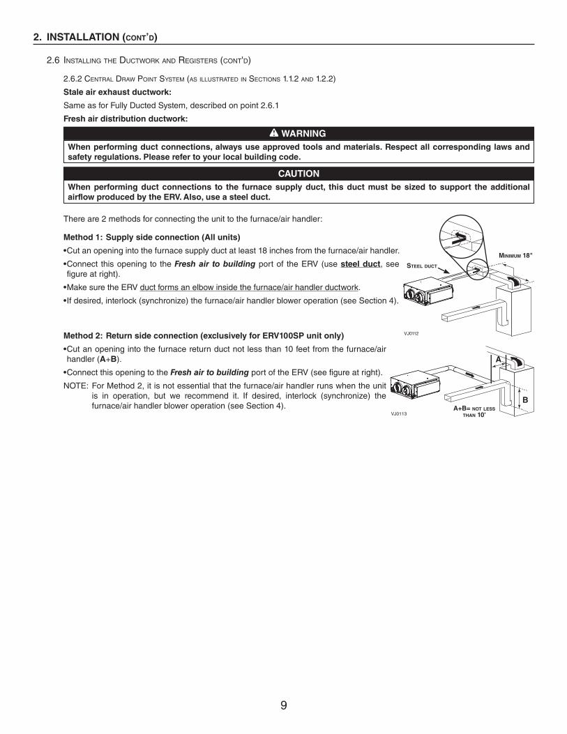
2.6.2 CENTRAL DRAW POINT SYSTEM (AS ILLUSTRATED IN SECTIONS 1.1.2 AND 1.2.2)
Stale air exhaust ductwork:
Same as for Fully Ducted System, described on point 2.6.1
Fresh air distribution ductwork:
There are 2 methods for connecting the unit to the furnace/air handler:
Method 1: Supply side connection (All units)
• Cut an opening into the furnace supply duct at least 18 inches from the furnace/air handler.
• Connect this opening to the Fresh air to building port of the ERV (use steel duct, see figure at right).
• Make sure the ERV duct forms an elbow inside the furnace/air handler ductwork.
• If desired, interlock (synchronize) the furnace/air handler blower operation (see Section 4).
Method 2: Return side connection (exclusively for ERV100SP unit only)
• Cut an opening into the furnace return duct not less than 10 feet from the furnace/air handler (A+B).
• Connect this opening to the Fresh air to building port of the ERV (see figure at right).
NOTE: For Method 2, it is not essential that the furnace/air handler runs when the unit is in operation, but we recommend it. If desired, interlock (synchronize) the furnace/air handler blower operation (see Section 4).
WARNING
When performing duct connections, always use approved tools and materials. Respect all corresponding laws and
safety regulations. Please refer to your local building code.
!
CAUTION
When performing duct connections to the furnace supply duct, this duct must be sized to support the additional
airflow produced by the ERV. Also, use a steel duct.
VJ0112
STEEL DUCT
MINIMUM 18"
B
A
VJ0113A+B= NOT LESS
THAN 10'
10
2. INSTALLATION (CONT’D)
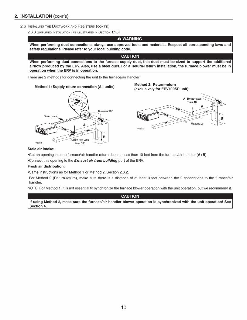
2.6 INSTALLING THE DUCTWORK AND REGISTERS (CONT’D)2.6.3 SIMPLIFIED INSTALLATION (AS ILLUSTRATED IN SECTION 1.1.3)
There are 2 methods for connecting the unit to the furnace/air handler:
Stale air intake:
• Cut an opening into the furnace/air handler return duct not less than 10 feet from the furnace/air handler (A+B).
• Connect this opening to the Exhaust air from building port of the ERV.
Fresh air distribution:
• Same instructions as for Method 1 or Method 2, Section 2.6.2.
For Method 2 (Return-return), make sure there is a distance of at least 3 feet between the 2 connections to the furnace/air handler.
NOTE: For Method 1, it is not essential to synchronize the furnace blower operation with the unit operation, but we recommend it.
CAUTION
When performing duct connections to the furnace supply duct, this duct must be sized to support the additional
airflow produced by the ERV. Also, use a steel duct. For a Return-Return installation, the furnace blower must be in
operation when the ERV is in operation.
VJ0115
B
A
VJ0114
B
A
STEEL DUCT
MINIMUM 18"
A+B= NOT LESS
THAN 10'
MINIMUM 3'
A+B= NOT LESS
THAN 10'
CAUTION
If using Method 2, make sure the furnace/air handler blower operation is synchronized with the unit operation! See
Section 4.
WARNING
When performing duct connections, always use approved tools and materials. Respect all corresponding laws and
safety regulations. Please refer to your local building code.
!
Method 1: Supply-return connection (All units)Method 2: Return-return
(exclusively for ERV100SP unit)

11
2. INSTALLATION (CONT’D)
2.7 CONNECTING THE DUCTS TO THE UNIT
NOTE: All units ports were created to be connected to ducts having a minimum of 5” diameter, but if need be, they can be connected to bigger sized ducts by using an appropriate transition (e.g.: 5” diameter to 6” diameter transition).
Insulated flexible ducts:
All units have both Fresh air to building and Exhaust air to outdoors ports equipped with integrated balancing damper. Prior to install the insulated flexible ducts on, ensure these both ports have their dampers set to wide open position (See Section 2.2)
CAUTION
Make sure the balancing dampers are set to wide open position before connecting the ducts to the ports. Also, the
ductwork connecting Fresh air to building and Exhaust air to outdoors ports with exterior hood(s) must be made of
insulated ducts, all way long.
Pull back the insulation to expose the flexible duct.
Attach the flexible duct to the port using tie wrap.
Pull the insulation over the joint and tuck in between the inner and outer rings of the double collar, then pull down the vapor barrier (shaded part in illustrations below) over the insulation and tuck in between the inner and outer rings.
Apply duct tape to the joint (outer ring and vapor barrier) making an airtight seal. Avoid compressing the insulation when pulling the tape tightly around the joint. Compressed insulation loses its R value and causes water dripping due to condensation on the exterior surface of the duct.
Rigid ducts:
Use a small length (6” length) of flexible duct to connect the rigid duct to the ports in order to avoid vibration transmissions. Use tie-wraps to perform connections, then seal with duct tape.
CAUTION
Do not use screws to connect the rigid ducts to the ports.
Use the following procedure for connecting the insulated flexible ducts to the port of the unit (Exhaust air to outdoors and Fresh air from outdoors ports).
CAUTION
If ducts have to go through an unconditioned space (e.g.: attic), always use insulated ducts.
� � �
VJ0117
�
CAUTION
Make sure the vapor barrier on the insulated ducts does not tear during installation to avoid condensation within the
ducts.
12
2. INSTALLATION (CONT’D)
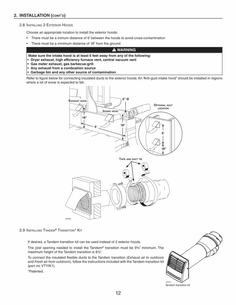
2.8 INSTALLING 2 EXTERIOR HOODS
Choose an appropriate location to install the exterior hoods:
• There must be a inimum distance of 6’ between the hoods to avoid cross-contamination
• There must be a minimum distance of 18” from the ground
Refer to figure below for connecting insulated ducts to the exterior hoods. An “Anti-gust intake hood” should be installed in regions where a lot of snow is expected to fall.
WARNING
Make sure the intake hood is at least 6 feet away from any of the following:
• Dryer exhaust, high efficiency furnace vent, central vacuum vent
• Gas meter exhaust, gas barbecue-grill
• Any exhaust from a combustion source
• Garbage bin and any other source of contamination
!
VD0028
EXHAUST HOOD
INTAKE HOOD
TAPE AND DUCT TIE
18"
6'
18"
18"
6'
6" Ø
OPTIONAL DUCT LOCATION
2.9 INSTALLING TANDEM® TRANSITION* KIT
If desired, a Tandem transition kit can be used instead of 2 exterior hoods.
The joist opening needed to install the Tandem® transition must be 9¾” minimum. The maximum height of the Tandem transition is 8¾”.
To connect the insulated flexible ducts to the Tandem transition (Exhaust air to outdoors and Fresh air from outdoors), follow the instructions included with the Tandem transition kit (part no. VTYIK1).
*Patented.
VR0003
Tandem transition kit
13
3. CONTROLS
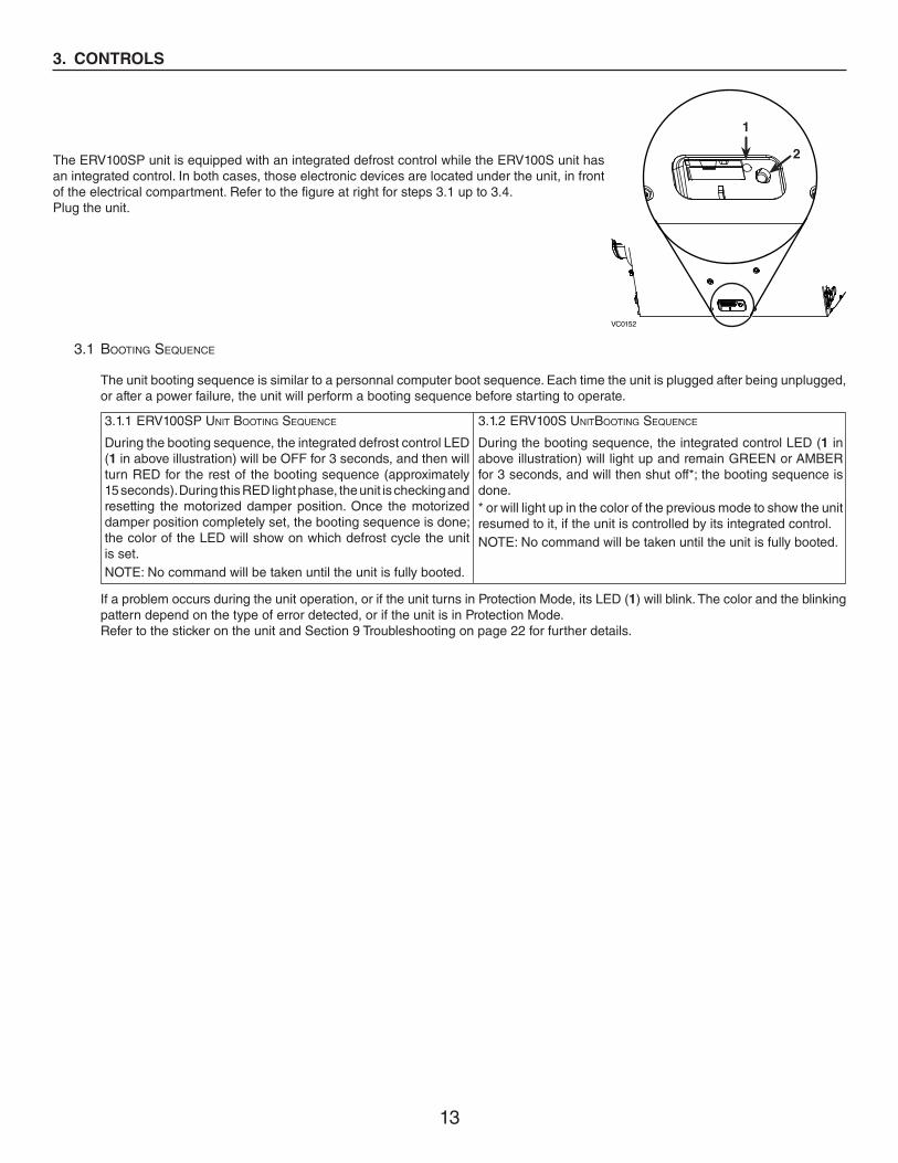
The ERV100SP unit is equipped with an integrated defrost control while the ERV100S unit has an integrated control. In both cases, those electronic devices are located under the unit, in front of the electrical compartment. Refer to the figure at right for steps 3.1 up to 3.4. Plug the unit.
The unit booting sequence is similar to a personnal computer boot sequence. Each time the unit is plugged after being unplugged, or after a power failure, the unit will perform a booting sequence before starting to operate.
If a problem occurs during the unit operation, or if the unit turns in Protection Mode, its LED (1) will blink. The color and the blinking pattern depend on the type of error detected, or if the unit is in Protection Mode. Refer to the sticker on the unit and Section 9 Troubleshooting on page 22 for further details.
3.1 BOOTING SEQUENCE
During the booting sequence, the integrated defrost control LED (1 in above illustration) will be OFF for 3 seconds, and then will turn RED for the rest of the booting sequence (approximately 15 seconds). During this RED light phase, the unit is checking andresetting the motorized damper position. Once the motorized damper position completely set, the booting sequence is done; the color of the LED will show on which defrost cycle the unit is set. NOTE: No command will be taken until the unit is fully booted.
3.1.1 ERV100SP UNIT BOOTING SEQUENCE
VC0152
1
2
During the booting sequence, the integrated control LED (1 in above illustration) will light up and remain GREEN or AMBER for 3 seconds, and will then shut off*; the booting sequence is done.* or will light up in the color of the previous mode to show the unit resumed to it, if the unit is controlled by its integrated control. NOTE: No command will be taken until the unit is fully booted.
3.1.2 ERV100S UNITBOOTING SEQUENCE
14
3. CONTROLS (CONT'D)
3.3 ERV100S UNIT INTEGRATED CONTROL
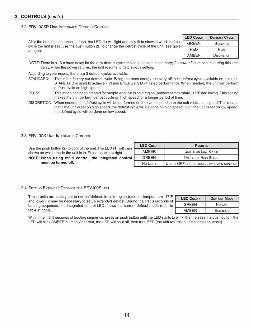
LED COLOR RESULTS
AMBER UNIT IS ON LOW SPEED
GREEN UNIT IS ON HIGH SPEED
NO LIGHT UNIT IS OFF OR CONTROLLED BY A MAIN CONTROL
Use the push button (2) to control the unit. The LED (1) will then shows on which mode the unit is in. Refer to table at right.NOTE: When using main control, the integrated control
must be turned off.
3.4 SETTING EXTENDED DEFROST FOR ERV100S UNIT
These units are factory set to normal defrost. In cold region (outdoor temperature -17°F and lower), it may be necessary to setup extended defrost. During the first 3 seconds of booting sequence, the integrated control LED shows the current defrost mode (refer to table at right).
LED COLOR DEFROST MODE
GREEN NORMAL
AMBER EXTENDED
Within the first 3 seconds of booting sequence, press on push button until the LED starts to blink, then release the push button; the LED will blink AMBER 5 times. After that, the LED will shut off, then turn RED (the unit returns in its booting sequence).
NOTE: There is a 15-minute delay for the new defrost cycle choice to be kept in memory; if a power failure occurs during this time delay, when the power returns, the unit resume to its previous setting.
3.2 ERV100SP UNIT INTEGRATED DEFROST CONTROL
After the booting sequence is done, the LED (1) will light and stay lit to show in which defrost cycle the unit is set. Use the push button (2) to change the defrost cycle of the unit (see table at right).
LED COLOR DEFROST CYCLE
GREEN STANDARD
RED PLUS
AMBER DISCRETION
According to your needs, there are 3 defrost cycles available:STANDARD: This is the factory set defrost cycle. Being the most energy recovery efficient defrost cycle available on this unit, STANDARD is used to achieve HVI and ENERGY STAR® listed performance. When needed, the unit will perform defrost cycle on high speed. PLUS: This mode has been created for people who live in cold region (outdoor temperature -17°F and lower). This setting makes the unit perform defrost cycle on high speed for a longer period of time.DISCRETION: When needed, the defrost cycle will be performed on the same speed than the unit ventilation speed. This means that if the unit is set on high speed, the defrost cycle will be done on high speed, but if the unit is set on low speed, the defrost cycle will be done on low speed.

15
3. CONTROLS (CONT'D)
The ERV100SP unit must be controlled by a main control. For more convenience, the ERV100S unit can also be controlled using an optional main control.
NOTES: 1. The integrated control must be turned OFF on ERV100S unit to use an optional main control. 2. If an optional auxiliary control is used, if activated, this auxiliary control will override the optional main control operation.
CAUTION
Never install more than one main wall control per unit. Make sure that the wires do not short-circuit between
themselves or by touching any other components on the wall control. Avoid poor wiring connections. To reduce
electrical interference (noise) potential, do not run wall control wiring next to control contactors or near light dimming
circuits, electrical motors, dwelling/building power or lighting wiring, or power distribution panel.
Check if all wires are correctly inserted in their corresponding holes in the terminal block. (A wire is correctly inserted when its orange receptacle is lower than another one without wire. On illustration at right, wire A is correctly inserted, but not wire B.)Splice back the end of the cable to access the 4 wires. Strip the end of each wire. Connect each wire to its corresponding terminal: YELLOW wire to “Y’’, RED wire to “R’’, GREEN wire to “G’’ and BLACK wire to “B’’. Connect the auxiliary control cable, if installed (not shown).
VE0272
A
B
3.5 ELECTRICAL CONNECTION TO WALL CONTROLS
WARNING
Always disconnect the unit before making any connections. Failure in disconnecting power could result in electric
shock or damage of the wall control or electronic module inside the unit.
!
Open the unit door. Insert the terminal connector (included in the installation kit) under the unit, on the electrical compartment front face. Use this terminal connector to perform the electrical connection for main and optional wall controls, then secure the cable(s) with a tie wrap (see illustration at right).
VE0297
TIE WRAP

16
3. CONTROLS (CONT'D)
3.5 ELECTRICAL CONNECTION TO WALL CONTROLS (CONT'D)
3.5.1 ELECTRICAL CONNECTION TO VT8W MAIN WALL CONTROL
(ERV100SP UNIT ONLY)
3.5.2 ELECTRICAL CONNECTION TO VT7W MAIN WALL CONTROL (ALL UNITS)
3.5.3 ELECTRICAL CONNECTION TO
VT4W MAIN WALL CONTROL (ALL UNITS)3.5.4 ELECTRICAL CONNECTION TO
VT6W MAIN WALL CONTROL (ALL UNITS)
NO C NC I OC OL Y R G B
VE0181
SMARTSETMODEPREF
NO C NC I OC OL Y R G B
VE0250
NO C NC I OC OL Y R G B
- -5°C23°F
5°C41°F
CO
MFO
RT
ZO
NE
-20°C-4°F
OFF MIN MAX
#XX
XX
X
01/98
VE0370
3.5.5 ELECTRICAL CONNECTION TO OPTIONAL AUXILIARY WALL CONTROLS
(59W: ALL UNITS, VB60W: ERV100SP UNIT ONLY AND VB20W: ERV100S UNIT ONLY)
NOTE: If an optional auxiliary wall control is activated, this control will override the main wall control commands.
Once the wall control(s) connections have been made and checked, close the unit door.
NOTE: For information about the operation of the wall controls, refer to the Main and auxiliairay wall controls user guide.
NO C NC I OC OL Y R G B
B G G B Y
VE0328A
Y
VT4WMAIN WALL CONTROL
REAR VIEW
NO C NC I OC OL Y R G B
VE0371
59W VB60W OR VB20W
17
4. ELECTRICAL CONNECTION TO THE FURNACE
WARNING
Never connect a 120-volt AC circuit to the terminals of the furnace interlock (standard wiring). Only use the low voltage class
2 circuit of the furnace blower control.
!
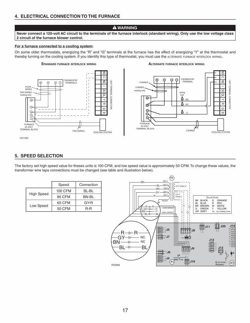
For a furnace connected to a cooling system:
On some older thermostats, energizing the “R” and “G” terminals at the furnace has the effect of energizing “Y” at the thermostat and thereby turning on the cooling system. If you identify this type of thermostat, you must use the ALTERNATE FURNACE INTERLOCK WIRING.
STANDARD FURNACE INTERLOCK WIRING ALTERNATE FURNACE INTERLOCK WIRING
W R G Y
W
R
G
C
Y
UN
IT T
ER
MIN
AL C
ON
NE
CTO
R
THERMOSTAT TERMINALS
FOUR WIRES
TWO WIRES heating only
FURNACE 24-VOLT
TERMINAL BLOCK TWO WIRES
COOLING SYSTEM
NO C
NC I OC O
L Y R G
B
W R G Y
W
R
Y
R
G
Y
C
THERMOSTAT TERMINAL 4 WIRES
2 WIRES
heating only wiring nuts
FURNACE 24-VOLT
TERMINAL BLOCK 2 WIRES
COOLING SYSTEM
NO
NC
C
UN
IT T
ER
MIN
AL C
ON
NE
CTO
R
NO C
NC I OC
OL Y R
G B
VE0108A
5. SPEED SELECTION
The factory set high speed value for theses units is 100 CFM, and low speed value is approximately 50 CFM. To change these values, the transformer wire taps connections must be changed (see table and illustration below).
Speed Connection
High Speed100 CFM BL-BL
85 CFM BN-BL
Low Speed65 CFM GY-R
50 CFM R-R
J1410987654321
J20
1 2
J13
ICP
A1ELECTRONICASSEMBLY
12
34
5
J12
J11
1 2
4 3 2 1
J9
J10
2 1
F1
3A
3AG TYPE
3 2 1JU1
M H
4 3 2 15
J8J5
J7
1
1
2
2
3
J612
J4123
T1
24 V Class 2
9.5 VClass 2
120 V
103 V
76 V
64 V
55 V
neutral
BKBL
BNGY
R
W
R RGY
BNBL BL
NCNC Y
Y
O
O
VE0299A
R RGY
BNBL BL
NCNC
LOW SPEED
HIGH SPEED
COLOR CODE
BLACKBLUEBROWNGREENGREY
BKBLBRGGR
ORANGEREDWHITEYELLOW
ORWYNC NO CONNECTION
18
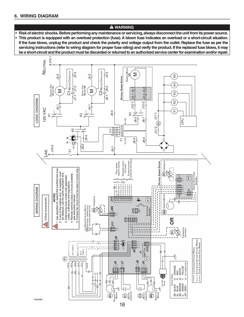
6. WIRING DIAGRAM
WARNING
• Risk of electric shocks. Before performing any maintenance or servicing, always disconnect the unit from its power source.
• This product is equipped with an overload protection (fuse). A blown fuse indicates an overload or a short-circuit situation.
If the fuse blows, unplug the product and check the polarity and voltage output from the outlet. Replace the fuse as per the
servicing instructions (refer to wiring diagram for proper fuse rating) and verify the product. If the replaced fuse blows, it may
be a short-circuit and the product must be discarded or returned to an authorized service center for examination and/or repair.
!
LIN
EN
EU
TR
AL
120
VA
C
J10-
2J1
0-1
EX
HA
US
T F
AN
MO
TOR M
1
M
C1
MO
TO
R C
AP
AC
ITO
R
K1
J5-1
J5-2
J7-1
J7-2
J5-3
SU
PP
LY F
AN
MO
TOR M
2
M
C2
MO
TO
R C
AP
AC
ITO
R
K3
J4-1
J4-2
J6-1
J6-2
J4-3
J9-4
OP
TIO
NA
L D
AM
PE
R S
YS
TE
M
DA
MP
ER M
OTO
RM
3 MJ2
-1J3
-1
J2-2
J3-2
J12-
1
J12-
2
K4
J8-2
J8-1
J8-5
J8-4
J11-
1J1
1-2
S1
K4
K1
K2
K3
K5
+-
~~
T1
9.5
VA
C24
VA
C
103 VAC76 VAC64 VAC55 VAC
NC
NC
J9-1
J9-3
J9-2
F1
32
1
JU1
MH
WIR
ING
DIA
GR
AM
LIN
E V
OLT
AG
E F
AC
TOR
Y W
IRIN
G
CLA
SS 2
LO
W V
OLT
AG
E F
AC
TOR
Y W
IRIN
G
CLA
SS 2
LO
W V
OLT
AG
E F
IELD
WIR
ING
OV
ER
RID
E S
WIT
CH
(OP
TIO
NA
L)
FIE
LD W
IRIN
GR
EM
OT
E C
ON
TR
OL
FU
RN
AC
E B
LOW
ER
INT
ER
LOC
K (
OP
TIO
NA
L)
B G RR
GB
K
YY
OL
OC I
J14
10 9 8 7 6 5 4 3 2 1
J20
12 J
13
ICP
A1
ELE
CT
RO
NIC
AS
SE
MB
LY
12345
J12
J11
12
43
21
J9 J10
21
F1
3A
3AG
TY
PE
32
1JU
1M
H
43
21
5
J8
J5
J7
1 12 23
J6
12 J4
1 2 3
21
54
32
11
2
J3
J2
J1
M3
A2
TH
ER
MIS
TOR
DA
MP
ER E
LEC
TR
ON
ICA
SS
EM
BLY
DA
MP
ER M
OTO
RR
1
BK
BK
BK W
G12
0 V
AC
60 H
z
C2
M2
BL
BR
BK
M1
C1
BL
BRBK
SU
PP
LY F
AN
MO
TOR
EX
HA
US
T F
AN
MO
TOR
MO
TOR
CA
PAC
ITO
R
MO
TOR
CA
PAC
ITO
R
T1
24 V
Cla
ss 2
9.5
VC
lass
2
120
V
103
V
76 V
64 V
55 V
neut
ral
BK
BL
BN
GY
R
W
RR
GY
BN
BL
BL
NC
NC
Y
Y
O
OW
S1
R2
DO
OR IN
TE
RLO
CK S
WIT
CH
(OP
TIO
NA
L, M
AG
NE
TIC
ALL
YA
CT
UAT
ED R
EE
D S
WIT
CH) T
HE
RM
ISTO
R
W
OP
TIO
NA
L D
AM
PE
R S
YS
TE
M
Crit
ical
cha
ract
eris
tic.
NO
TE
S1.
Use
spe
cifie
d U
L lis
ted/
CS
A C
ertif
ied
line
fuse
.2.
If a
ny o
f the
orig
inal
wire
, as
supp
lied,
mus
tbe
rep
lace
d, u
se th
e sa
me
equi
vale
nt w
ire.
3. F
ield
wiri
ng m
ust c
ompl
y w
ith a
pplic
able
code
s, o
rdin
ance
s an
d re
gula
tions
.4.
Rem
ote
cont
rols
(cl
ass
2 ci
rcui
t) a
vaila
ble,
see
inst
ruct
ion
man
ual.
5. F
urna
ce fa
n ci
rcui
t mus
t be
clas
s 2
circ
uit o
nly.
K2
CP
U
LOG
IC D
IAG
RA
M
VE0298A
CO
LOR C
OD
E
BLA
CK
BLU
EB
RO
WN
GR
EE
NG
RE
Y
BK
BL
BR
G GR
OR
AN
GE
RE
DW
HIT
EY
ELL
OW
O R W Y NC
NO C
ON
NE
CT
ION
R1
TH
ER
MIS
TOR
(OP
TIO
NA
L)
OR

19
7. BALANCING THE UNIT
7.1 WHAT YOU NEED TO BALANCE THE UNIT
• A magnehelic gauge capable of measuring 0 to 0.5 inch of water (0 to 125 Pa) and 2 plastic tubes.
• The balancing chart located on the unit door.
7.2 PRELIMINARY STAGES TO BALANCE THE UNIT
• Seal all the unit ductwork with tape. Close all windows and doors. • Turn off all exhaust devices such as range hood, dryer and bathroom fans. • Make sure the integrated balancing dampers are fully open. Both are located on the Exhaust air to
outdoor port and on Fresh air from outdoor port (see step 2.2).
• Make sure all filters are clean (if it is not the first time you balance the unit).
7.3 BALANCING PROCEDURE
1. Set the unit to high speed.
Make sure that the furnace/air handler blower is ON if the installation is in any way connected to the ductwork of the cold air return. If not, leave furnace/air handler blower OFF.
2. Place the magnehelic gauge on a level surface and adjust it to zero.
3. Connect tubing from gauge to exhaust air flow pressure taps and fresh airflow pressure taps (see diagram at right).
Be sure to connect the tubes to their appropriate high/low fittings. If the gauge drops below zero, reverse the tubing connections.
4. Measure both flows; adjust higher flow to equal the lower one, using balancing damper lever.
5. Secure both damper levers in place using their locking screw, then shut all the pressure taps with the small plastic plugs included in the hardware kit.
6. Write the required air flow information on a label and stick it near the unit for future reference (date, maximum speed air flows, your name, phone number and business address).
NOTE: The unit is considered balanced even if there is a difference of ±10 cfm between the two air flows.
VP0009
VJ0116
EXHAUST AIRFLOW
FRESH AIRFLOW
LOW
HIGH
LOW
HIGH
VP0025A
VD0333
CAUTION
Make sure to turn the damper lever to the right direction (opposite to its
stopper, see illustration at right). Securing the lever in wrong position may
cause freezing into the unit.
CAUTION
When loosing or tightening the damper lever locking screw, never use an electric screwdriver or
drill, use a standard screwdriver.
VR0086
Make sure the unit is not running in defrost mode while balancing.
When the outdoor temperature is below 32°F, the defrost mode can be activated. During defrost cycle, it is not possible to balance the unit since there is no flow in one direction.To cancel the defrost cycle, use the auxiliary control or jump OC-OL on unit terminal block; this will set the unit on high speed ventilation without defrost for the next 20 minutes. Once the 20 minutes of high speed ventilation is completed, the unit will perform an extended defrost. If installed, do not forget to remove the jumper between OL and OC on terminal block.Another way to avoid the defrost cycle is to wait 10 minutes after plugging the unit in; this procedure ensures that the unit is not in a defrost cycle.NOTE: Both units start in defrost mode within the first minute of operation.
20
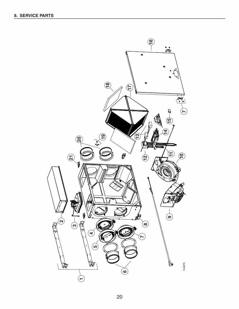
8. SERVICE PARTS
VL0
075
10
2
3
45
6
78
9
13
12
16
7
17
21
1
11
19
14
15
18
20

21
NO.
DE
SC
RIP
TIO
NP
AR
T N
O.
ER
V10
0S
ER
V10
0S
P
1IN
STA
LLAT
ION B
RA
CK
ET
S K
IT (
2)S
V61
240
11
2R
EC
IRC
ULA
TIO
N C
HA
NN
EL
KIT
SV
6121
31
3D
AM
PE
R S
YS
TE
M K
ITS
V61
214
1
4B
ALA
NC
ING P
OR
T K
ITS
V61
216
1
5B
ALA
NC
ING A
ND B
AC
KD
RA
FT D
AM
PE
R P
OR
T K
ITS
V61
219
1
65”
ME
TAL
PO
RT K
IT F
OR C
OLD
SID
ES
V61
236
22
7A
DJU
STA
BLE
PO
RT K
ITS
V61
215
11
8D
OO
R M
ETA
L K
EE
PE
RS A
ND L
ATC
HE
S K
ITS
V61
218
11
9D
OO
R B
RA
CK
ET K
ITS
V61
220
10C
OLD
SID
E B
LOW
ER K
IT (
INC
L. 1
CA
PAC
ITO
R)
SV
6123
51
1
11W
AR
M S
IDE B
LOW
ER K
IT (I
NC
L.1
CA
PAC
ITO
R A
ND IT
EM
12)
SV
6123
41
1
12W
AR
M S
IDE T
HE
RM
ISTO
RS
V61
233
11
13T
RA
NS
FO
RM
ER K
ITS
V61
232
11
14C
APA
CIT
OR
S 5
µF
(2)
SV
1604
21
1
15E
LEC
TR
ON
IC B
OA
RD K
ITS
V61
229
1
SV
6123
01
16M
AG
NE
T W
ITH B
RA
CK
ET K
ITS
V61
241
11
17D
OO
R A
SS
EM
BLY
SV
6349
81
1
18F
ILT
ER K
IT (
2)S
V21
029
11
OP
TIO
NA
L M
ER
V 7
FIL
TE
RS (
2)V
2103
01
1
19E
RV
CO
RE
SV
6122
31
1
20C
OR
E L
OC
KIN
G D
EV
ICE K
ITS
V61
237
11
215”
ME
TAL
PO
RT K
IT F
OR W
AR
M S
IDE
SV
6121
72
2
22D
OO
R M
ETA
L H
ING
ES K
IT (
2)S
V61
228
22
*T
ER
MIN
AL
CO
NN
EC
TOR
SV
1641
61
1
*C
OLD
SID
E T
HE
RM
ISTO
R K
ITS
V61
221
1
*O
PT
ION
AL
HA
RD
WA
RE K
ITV
6123
91
1
* N
OT S
HO
WN.
8. SERVICE PARTS (CONT'D)
RE
PL
AC
EM
EN
T P
AR
TS A
ND R
EP
AIR
In o
rder
to e
nsur
e yo
ur v
entil
atio
n un
it re
mai
ns in
goo
d w
orki
ng c
ondi
tion,
you
mus
t use
the
Bro
an-N
uTon
e LL
C g
enui
ne re
plac
emen
t par
ts o
nly.
The
Bro
an-N
uTon
e LL
C g
enui
ne re
plac
emen
t par
ts
are
spec
ially
des
igne
d fo
r ea
ch u
nit
and
are
man
ufac
ture
d to
com
ply
with
all
the
appl
icab
le c
ertif
icat
ion
stan
dard
s an
d m
aint
ain
a hi
gh s
tand
ard
of s
afet
y. A
ny t
hird
par
ty r
epla
cem
ent
part
use
d m
ay c
ause
ser
ious
dam
age
and
dras
tical
ly r
educ
e th
e pe
rfor
man
ce le
vel o
f you
r un
it, w
hich
will
res
ult i
n pr
emat
ure
faili
ng. A
lso,
Bro
an-N
uTon
e LL
C r
ecom
men
ds to
con
tact
a B
roan
-NuT
one
LLC
ce
rtifi
ed s
ervi
ce d
epot
for
all r
epla
cem
ent p
arts
and
rep
airs
.

22
9. TROUBLESHOOTING
If the unit does not work properly, reset the unit by unplugging it for one minute and then replug it. If it still not working properly,
refer to table below.
If the LED of the unit is flashing, this means the unit sensors have detected a problem. See the table below to know where the problem occurs on the unit.
LED SIGNAL ERROR TYPE ACTION UNIT STATUS
LED flashes GREEN(double blink every 2 seconds).
Outdoor thermistor error. • Ensure J12 connector is properly connectedand its wires are not damaged. If they arecorrect:
• For ERV100SP unit: replace the damper assembly.
• For ERV100S unit: replace the fresh air from outdoor thermistor.
Unit works but will defrost frequently.
LED flashes GREEN (2 blinks per second; faster blink).
Building side thermistor error. • Ensure J20 connector is properly connectedand its wires are not damaged. If they are correct:
• Replace the thermistor in the warm side blower.
Unit does not work.
LED flashes AMBER(ERV100SP unit only).
Damper system error. • Go to point 7 in next table. Unit does not work.
LED flashes RED(one blink every 2 seconds).
Cold side motor error, open door or magnetic switch bad contact.
For ERV100SP unit: • Check if the unit door is properly closed, then
push once on integrated push button to restart unit.
• Check for the door magnet to be properly seated onto the door. If not, correct the situation, close the door and push once on the integrated push button to restart unit.
• Ensure J11 connector is properly connectedand its wires are not damaged. If not, correct the situation, close the door and push once on the integrated push button to restart unit.
For all units:• Using a flat blade screwdriver, jump J11 while
pushing once on push button at the same time. If the LED is still flashing, go to point 8 in next
table for motor diagnosis.
Unit does not work.
LED flashes RED (2 blinks per second; faster blink).
Unit is on protection mode or is in error because it has been in protection mode for an abnormal time.
• If outdoor temperature is colder than -13°F, it could be normal for the unit to enter in protection mode.
• To see if the unit is in error, wait 5 minutes,unplug the unit, wait 1 minute and plug it back. Wait for the booting sequence to be done, then see if it still shows this error. If yes, press and hold the push button during 7 seconds to reset this error. Another LED signal can happen; refer to the appropriate LED color code and blinks. If no, go to point 9 in next table.
Unit exhaust air without entering fresh air for a 2-hour period, then resume to its previous operation mode and stops flashing RED. If LED continues to flash RED when back to previous mode, the unit is in error. Go to point 9 in next table.
23
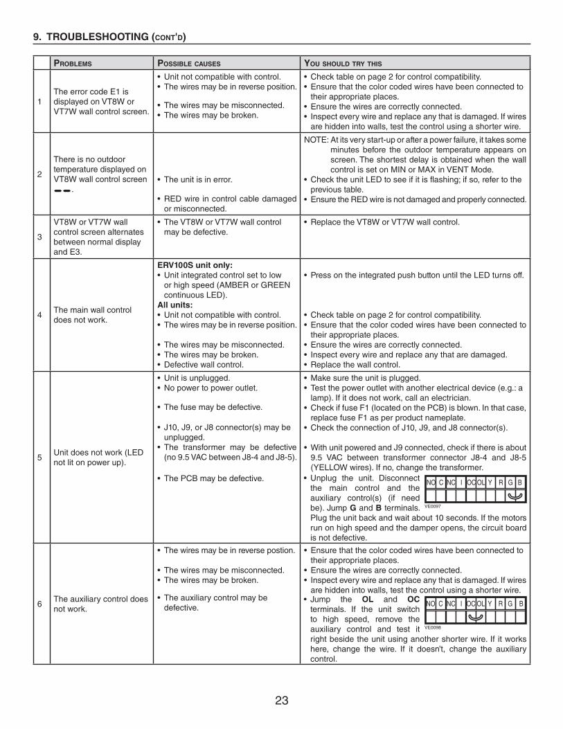
9. TROUBLESHOOTING (CONT'D)
• Unplug the unit. Disconnect the main control and the auxiliary control(s) (if need be). Jump G and B terminals. Plug the unit back and wait about 10 seconds. If the motors run on high speed and the damper opens, the circuit board is not defective.
NO C NC I OC OL Y R G B
VE0097
PROBLEMS POSSIBLE CAUSES YOU SHOULD TRY THIS
1The error code E1 is displayed on VT8W or VT7W wall control screen.
• Unit not compatible with control.• The wires may be in reverse position.
• The wires may be misconnected.• The wires may be broken.
• Check table on page 2 for control compatibility.• Ensure that the color coded wires have been connected to
their appropriate places.• Ensure the wires are correctly connected.• Inspect every wire and replace any that is damaged. If wires
are hidden into walls, test the control using a shorter wire.
2
There is no outdoor temperature displayed on VT8W wall control screen __.
• The unit is in error.
• RED wire in control cable damaged or misconnected.
NOTE: At its very start-up or after a power failure, it takes some minutes before the outdoor temperature appears on screen. The shortest delay is obtained when the wall control is set on MIN or MAX in VENT Mode.
• Check the unit LED to see if it is flashing; if so, refer to the previous table.• Ensure the RED wire is not damaged and properly connected.
3
VT8W or VT7W wall control screen alternates between normal display and E3.
• The VT8W or VT7W wall control may be defective.
• Replace the VT8W or VT7W wall control.
4The main wall control does not work.
ERV100S unit only:
• Unit integrated control set to low or high speed (AMBER or GREEN continuous LED).
All units:
• Unit not compatible with control.• The wires may be in reverse position.
• The wires may be misconnected.• The wires may be broken.• Defective wall control.
• Press on the integrated push button until the LED turns off.
• Check table on page 2 for control compatibility.• Ensure that the color coded wires have been connected to
their appropriate places.• Ensure the wires are correctly connected.• Inspect every wire and replace any that are damaged.• Replace the wall control.
5Unit does not work (LED not lit on power up).
• Unit is unplugged.• No power to power outlet.
• The fuse may be defective.
• J10, J9, or J8 connector(s) may be unplugged.• The transformer may be defective (no 9.5 VAC between J8-4 and J8-5).
• The PCB may be defective.
• Make sure the unit is plugged.• Test the power outlet with another electrical device (e.g.: a lamp). If it does not work, call an electrician.• Check if fuse F1 (located on the PCB) is blown. In that case,
replace fuse F1 as per product nameplate.• Check the connection of J10, J9, and J8 connector(s).
• With unit powered and J9 connected, check if there is about 9.5 VAC between transformer connector J8-4 and J8-5 (YELLOW wires). If no, change the transformer.
6The auxiliary control does not work.
• The wires may be in reverse postion.
• The wires may be misconnected.• The wires may be broken.
• The auxiliary control may be defective.
• Ensure that the color coded wires have been connected to their appropriate places.
• Ensure the wires are correctly connected.• Inspect every wire and replace any that is damaged. If wires
are hidden into walls, test the control using a shorter wire.• Jump the OL and OC
terminals. If the unit switch to high speed, remove the auxiliary control and test it right beside the unit using another shorter wire. If it works here, change the wire. If it doesn’t, change the auxiliary control.
NO C NC I OC OL Y R G B
VE0098

24
9. TROUBLESHOOTING (CONT'D)
PROBLEMS POSSIBLE CAUSES YOU SHOULD TRY THIS
7
The damper system does not work (ERV100SP unit only)(AMBER error code).
At power up, no RED LED.At power up, LED lights RED and
there is a clicking sound coming
from electrical compartment, but
damper does not move:• Ice or other things hindering the damper movement.• J12 unconnected or bad contact.• Wrong connection of J8.• The transformer may be defective (no 24 VAC between J8-1 and J8-2).
• The damper actuator may be defective.Damper moves but does not stop
when supposed to:• Bad connection of J12 connector.• Damper PCB defective or damper
motor stripped gear.• The main PCB is defective.
• See point 5.
• Remove ice or hindering elements.
• Check J12 connection (both harness side and board side).• Check J8 connection.• With unit powered and J9 connected, check if there is about
20-24 VAC between transformer connector J8-1 and J8-2 (ORANGE wires). If no, change the transformer.
• Replace the damper system.
• Check J12 connection (both harness side and board side).• Replace the damper system.
• Replace the main PCB.
8
A. The supply motor does not work, but exhaust motor works.
B. The LED flashes RED.
• The supply motor may be defective.
• The supply motor capacitor or the PCB may be defective.
• The exhaust motor may be defective.
• The exhaust motor capacitor may be defective.
• Tranformer wire(s) bad connection.
• The transformer or the PCB may be defective.
• Plug supply motor to J5 connector and exhaust motor to J4 connector. If the LED flashes RED, the supply motor is defective. If exhaust motor works, plug back supply motor to J4 connector and exhaust motor to J5 connector, then check for supply motor capacitor validity.
• Plug supply motor capacitor to J7 connector and exhaust motor capacitor to J6 connector. If the LED flashes RED, the supply motor capacitor is defective. If there is no change, the PCB is defective.
• Plug exhaust motor to J4 connector and supply motor to J5 connector. If supply motor works but exhaust motor does not, exhaust motor is defective. If exhaust motor works, plug back supply motor to J4 connector and exhaust motor to J5 connector, then check for exhaust motor capacitor validity.
• Plug exhaust motor capacitor to J6 connector and exhaust motor capacitor to J7 connector. If exhaust motor works but supply motor does not, the exhaust motor capacitor is defective. If there is no change, check validity of transformer or PCB.
• Check J8 and J9 connectors, as well as BLUE and RED wire connections from J9.
• Move JU1 jumper from pins 2 and 3 to pins 1 and 2. Set the unit on high speed. If exhaust motor works, the transformer is defective. If it still does not, change the PCB.
9Unit shows protection mode error (different than being in protection mode)
• Wrong selection of defrost cycle.• Defective motor or damper.
• Stale air flow choked (unbalanced unit, filters or outdoor port clogged, etc.).
• Inside temperature too low (around 64°F).
• Refer to Section 3.2 or 3.4, according to the unit model.• Inspect the complete unit, make sure both motors are
running, make sure the damper system closes and seal properly.
• Inspect the complete ducting, clean the filters, stale air inside grille, etc., balance the unit).
• Unit is using the inside temperature to defrost itself, so a very low room temperature can harm the defrost system of the unit.