installation guide & operation...
TRANSCRIPT

INSTALLATION INSTRUCTIONS FCS SERIES MODEL 50ECO # 1569 REVISION #0006
INSTALLATION GUIDE & OPERATION MANUAL
MOTOR OPERATOR
COVERED UNDER US PATENTS #6,900,602, #7,055,283 AND ADDITIONAL PATENTS PENDING
The Cookson Company, Inc
FCS SERIES MODEL 5025, 5045,7525 & 7545 INSTALLATION INSTRUCTIONS BY:
Page 1 of 30
INSTALLATION GUIDE & OPERATION MANUAL
MOTOR OPERATOR (V3.02 Controls)
FCS SERIES
MODEL 5045 & 5025 1/2 HP
&
FCS SERIES MODEL 7545 & 7525
3/4 HP
FCS SERIES, U.S. GEAR COVERED UNDER US PATENTS #6,900,602, #7,055,283 AND ADDITIONAL PATENTS PENDING
The Cookson Company, Inc 2417 S. 50TH Avenue
Phoenix, Arizona 85043 Phone: (602)272-4244 Fax: (866) 448-6798
ES 10-301 DATE: 01/23/2013
INSTALLATION GUIDE & OPERATION MANUAL
COVERED UNDER US PATENTS #6,900,602, #7,055,283 AND ADDITIONAL PATENTS PENDING

INSTALLATION INSTRUCTIONS FCS SERIES MODEL 5025, 5045,7525 & 7545 INSTALLATION INSTRUCTIONS
ES 10-301 ECO # 1569 REVISION #0006 BY: DATE: 01/23/2013
Page 2 of 30
TABLE OF CONTENTS
I. GENERAL NOTES .................................................................................................................. 3
II. SPECIFICATIONS .................................................................................................................. 3
III. INSTALLATION INSTRUCTIONS
1. Installation Positions ...................................................................................................... 4
2. Control Installation A. Control Box Mounting ........................................................................................... 5 B. Wiring Procedure for Operator and Control Panel ............................................... 7 C. Wiring Push Button or Key Switch ....................................................................... 11
3. Limit Switch Adjustment ................................................................................................. 11
4. Lead Post Wiring Instructions ........................................................................................
A. Precautions ........................................................................................................... 13 B. Procedure ............................................................................................................. 13
5. Check List ...................................................................................................................... 16
6. Wiring Diagrams ............................................................................................................ 17
7. Field Wiring Terminal Strip Connections ....................................................................... 21
8. Functions Table .......................................................................................................... 22
9. Output Warnings ............................................................................................................ 24
10. Sound Warnings .......................................................................................................... 24
11. Light Indication ............................................................................................................. 25
12. Switch Indication .......................................................................................................... 25
13. Function and Timer Set-Up Instruction…………………………………………………….26
IV. OPERATING INSTRUCTIONS .......................................................................................... 30
V. MAINTENANCE INSTRUCTIONS ......................................................................................... 30

INSTALLATION INSTRUCTIONS FCS SERIES MODEL 5025, 5045,7525 & 7545 INSTALLATION INSTRUCTIONS
ES 10-301 ECO # 1569 REVISION #0006 BY: DATE: 01/23/2013
Page 3 of 30
I. GENERAL NOTES
To reduce the risk of severe injury or death, read and follow all installation instructions.
• The operator must be installed by qualified door mechanics using proper tools and equipment.
• Make sure the available power supply to be connected to the operator is of the same voltage, frequency and phase as indicated on the nameplate of the control panel.
• Read and understand the manual before installing the operator.
• Read and understand the wiring diagram of the operator, control station and any other equipment to be connected to the operator.
• Always disconnect power when installing or servicing the door operator or door.
• All wiring is to comply with National Electrical Code (NEC) and local code requirements.
• Any change in mounting position may result in change of operator rotation and consequently in change of control functions. Consult factory for any changes.
II. SPECIFICATIONS
(1/2 HP) (3/4 HP)
INPUT FCS 5045 FCS 5025 FCS 7545 FCS 7525
Voltage 120VAC 208~240VAC 120VAC 208~240VAC
Phase 1 1 1 1
Frequency 60 Hz 50/60 Hz 60 Hz 50/60 Hz
Full Load Current 5.5 amps 2.75 amps 6 amps 3 amps
Wire Gauge 14 AWG 14 AWG 14 AWG 14 AWG
(1/2 HP) (3/4 HP)
MOTOR FCS 5045 FCS 5025 FCS 7545 FCS 7525
Horsepower 1/2 1/2 3/4 3/4
Voltage 24VDC 24VDC 24VDC 24VDC
Current 13 amps 13 amps 17 amps 17 amps
RPM 1700 1700 1700 1700
Gear Ratio 43:1 43:1 43:1 43:1
Output RPM 39 39 39 39
Door Speed 6 or 9 in/sec 6 or 9 in/sec 6 or 9 in/sec 6 or 9 in/sec
Sprocket Size 6 in/sec: 18T 6 in/sec: 18T 6 in/sec: 18T 6 in/sec: 18T
9 in/sec: 28T 9 in/sec: 28T 9 in/sec: 28T 9 in/sec: 28T
Drive Chain #40 #40 #40 #40
Duty 10 cycles/hour 10 cycles/hour 10 cycles/hour 10 cycles/hour
Rating1 140 ft-lb./sec
(1680 in-lb./sec) 140 ft-lb./sec
(1680 in-lb./sec) 180 ft-lb./sec
(2160 in-lb./sec) 180 ft-lb./sec
(2160 in-lb./sec)
Brake Solenoid Actuated Solenoid Actuated Solenoid Actuated Solenoid Actuated
Battery (2) 12V 17.2AH or above
(2) 12V 17.2AH or above
(2) 12V 17.2AH or above
(2) 12V 17.2AH or above
Wiring Diagram EP 107 A V3.02
EP 107 A (230) V3.02
EP 307 A V3.02
EP 307 A (230) V3.02
1Ratings tested at the output shaft.
ENTRAPMENT PROTECTION
Sensing Edge Sensing device attached to the leading edge of the door
Exit Bars Exit hardware positioned on each side of door to allow emergency exit.

INSTALLATION INSTRUCTIONS FCS SERIES MODEL 5025, 5045,7525 & 7545 INSTALLATION INSTRUCTIONS
ES 10-301 ECO # 1569 REVISION #0006 BY: DATE: 01/23/2013
Page 4 of 30
III. INSTALLATION INSTRUCTIONS
1. Installation Positions
Operator:
Operators are shipped as a complete unit and are fastened directly to the header using the provided lag screws.
Drill 1/4” pilot holes prior to installing the lag screws. A template that calls out the proper pilot hole locations will be provided with the operator.
Operator should be installed on the centerline of the header and butted up against the back wall of the pocket. Install (2) bolts into the pilot holes drilled at the back of the header. Leave 1/2” space between the header and the head of the lag bolt. Slide the operator onto the lag bolts making sure the operator is butted up against the back wall of the pocket. Hold the operator in place by installing (2)
#10 track screws through
the 1/4” holes located at the front of the motor bracket flange. Retrieve the remaining lag bolts and complete the operator installation by tightening all (4) lag bolts into the header.
HEADER
BACKWALL OFPOCKET
SLOTTED HOLESTOWARD POCKET
WALL
Figure 1.a. Installing Operator.

INSTALLATION INSTRUCTIONS FCS SERIES MODEL 5025, 5045,7525 & 7545 INSTALLATION INSTRUCTIONS
ES 10-301 ECO # 1569 REVISION #0006 BY: DATE: 01/23/2013
Page 5 of 30
2. Control Installation
A. Control Box Mounting
Locate and unpack the control box marked Box A. The Control Box should be installed on the back wall of the pocket using the appropriate fasteners based on the wall construction (not provided by Cookson). See Figure 2.a. The bottom of the Control Box should at least 24” from the finished floor to provide ample room for any junction boxes and wiring. Use the measurements provided in Figure 2.a and Figure 2.b to mark the required hole locations. Partially insert the top (2) fasteners, leaving approximately 1/4” between the back wall of the header and the fastener head. Position the Control Box mounts over the installed fasteners via the large area of the keyhole. Slide operator to control down so that the fasteners are positioned in the narrow, top portion of the keyhole. Tighten the fasteners. Insert fasteners in the narrow, top portion of the keyholes on the bottom (2) mounts.
Figure 2.a. Installed Control Box.
Figure 2.b. Control Box Hole Locations.

INSTALLATION INSTRUCTIONS FCS SERIES MODEL 5025, 5045,7525 & 7545 INSTALLATION INSTRUCTIONS
ES 10-301 ECO # 1569 REVISION #0006 BY: DATE: 01/23/2013
Page 6 of 30
Figure 2.c. Installed Operator and Control Box
A
A
ALL ELECTRICAL COMPONENTS TO BE INSTALLED IN
ACCORDANCE WITH LOCAL BUILDING CODE REQUIREMENTS.
NOTE:
FLEX
CONDUIT
24
" M
IN.
CONTROL BOX TO BE SURFACEMOUNTED AT THE BACK OF THE
POCKET 24" MIN. FROM THE FLOOR BYCOOKSON DOOR INSTALLER.
DC MOTORDRIVE UNIT
(BOX B)
PUSH BUTTON BYCOOKSON.
ALARM INPUT WIRING AND CONDUIT BY
ELECTRICAL CONTRACTOR.
4" X 4" "J" BOXES SURFACE MOUNTED 12"
ABOVE THE FINISHED FLOOR BY ELECTRICAL
CONTRACTOR.
CONDUIT FROM SURFACE MOUNTED "J" BOX
TO THE SWITCH WITH 4 CONDUCTOR LOW
VOLTAGE STRANDED HOOK-UP WIRE. 22GA.
MIN, 14GA. MAX BY ELECTRICALCONTRACTOR.
SUPPLY WIRING INTO "J" BOX WIRING ANDCONDUIT BY ELECTRICAL CONTRACTOR.
12"
CONTROL BOX(BOX A)
FOLDING FIREDOOR BY
COOKSON
SECTION THRU A

INSTALLATION INSTRUCTIONS FCS SERIES MODEL 5025, 5045,7525 & 7545 INSTALLATION INSTRUCTIONS
ES 10-301 ECO # 1569 REVISION #0006 BY: DATE: 01/23/2013
Page 7 of 30
Figure 2.d. Control Panel Door Latch
NEC Compliance Upgrades
To comply with the requirements for electrical installations per the National electric code, Kontrol Fire operator control panels are provided with a plunger switch that turns off power to the motor operator, and the 24VDC system at exposed terminals, as soon as the control panel door is opened beyond its latched position. The input power wire terminals are covered and labeled to “disconnect power before removing cover.” The DC battery terminals are also covered to limit contact with the 24 volt terminals and a fuse cover is provided for added protection. This setup is designed to prevent access to live wires within the control panel when the control box door is open.
B. Wiring Procedure for Operator and Control Panel
1. For BOX (A) Main Control Panel connections to Motor Operator BOX(B) � A separate circuit is recommended for the operator. � The flexible cable provided with the Main Control Panel contains all the wires that must be
connected to the Motor Operator. Connections are already made in the Main Control Panel. � Attach flexible cable to Box (B). � Field connections required at the Motor Operator are clearly marked on the terminal block end
of all wires.

INSTALLATION INSTRUCTIONS FCS SERIES MODEL 5025, 5045,7525 & 7545 INSTALLATION INSTRUCTIONS
ES 10-301 ECO # 1569 REVISION #0006 BY: DATE: 01/23/2013
Page 8 of 30
FCS-5045, FCS-7545 BATTERY SPECIFICATION (12VDC 17.2AH*2)
Figure 2.e. Battery Diagram
2. For BOX (A) Battery Enclosure
1 BAT1(-) → BAT2(+) (QC= red quick connect plug) 2 BAT1(+) → QC1(+)
3 BAT2(-) → QC1(-)
3. Connections required at Motor Operator BOX (B):
See Figure 2.f. DC Motor Connections located on page 9 and 10.

INSTALLATION INSTRUCTIONS FCS SERIES MODEL 5025, 5045,7525 & 7545 INSTALLATION INSTRUCTIONS
ES 10-301 ECO # 1569 REVISION #0006 BY: DATE: 01/23/2013
Page 9 of 30
Figure 2.f. DC Motor Connections
Limit Switch (LS)
Limit Switch (LS)

INSTALLATION INSTRUCTIONS FCS SERIES MODEL 5025, 5045,7525 & 7545 INSTALLATION INSTRUCTIONS
ES 10-301 ECO # 1569 REVISION #0006 BY: DATE: 01/23/2013
Page 10 of 30
Limit Switch (LS)
Limit Switch (LS)
INSTALLATION INSTRUCTIONS FCS SERIES MODEL 5025, 5045,7525 & 7545 INSTALLATION INSTRUCTIONS
ES 10-301 ECO # 1569 REVISION #0006 BY: DATE: 01/23/2013
Page 11 of 30
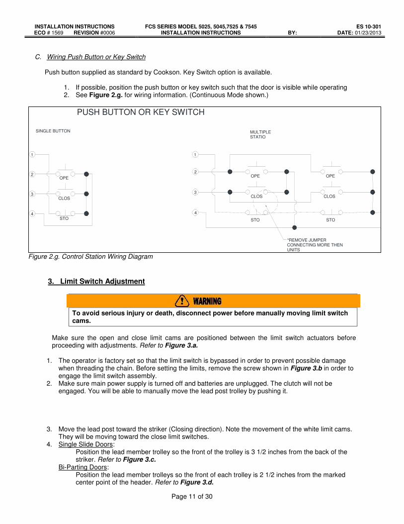
C. Wiring Push Button or Key Switch
Push button supplied as standard by Cookson. Key Switch option is available.
1. If possible, position the push button or key switch such that the door is visible while operating 2. See Figure 2.g. for wiring information. (Continuous Mode shown.)
Figure 2.g. Control Station Wiring Diagram
3. Limit Switch Adjustment
To avoid serious injury or death, disconnect power before manually moving limit switch cams.
Make sure the open and close limit cams are positioned between the limit switch actuators before proceeding with adjustments. Refer to Figure 3.a.
1. The operator is factory set so that the limit switch is bypassed in order to prevent possible damage
when threading the chain. Before setting the limits, remove the screw shown in Figure 3.b in order to engage the limit switch assembly.
2. Make sure main power supply is turned off and batteries are unplugged. The clutch will not be engaged. You will be able to manually move the lead post trolley by pushing it.
3. Move the lead post toward the striker (Closing direction). Note the movement of the white limit cams. They will be moving toward the close limit switches.
4. Single Slide Doors: Position the lead member trolley so the front of the trolley is 3 1/2 inches from the back of the striker. Refer to Figure 3.c.
Bi-Parting Doors: Position the lead member trolleys so the front of each trolley is 2 1/2 inches from the marked center point of the header. Refer to Figure 3.d.
OPE CLOS STO
PUSH BUTTON OR KEY SWITCH
1
2
3
4
SINGLE BUTTON
1
2
3
4
OPE CLOS
STO
OPE CLOS
STO *REMOVE JUMPER CONNECTING MORE THEN UNITS
MULTIPLE STATIO

INSTALLATION INSTRUCTIONS FCS SERIES MODEL 5025, 5045,7525 & 7545 INSTALLATION INSTRUCTIONS
ES 10-301 ECO # 1569 REVISION #0006 BY: DATE: 01/23/2013
Page 12 of 30
5. Set the close limit by depressing the spring-loaded locking bar (G). Rotate the white limit cam closest
to the close limit until it trips the bottom switch on the close limit side. Release the locking bar (G) and make sure the upturned lip is engaged in a slot on each limit cam. This insures that your setting is maintained.
6. Manually move the lead post trolley into the pocket. The white limit cam will be moving toward the open limits.
7. Position the lead post trolley in the pocket area so the front of the trolley is 6 inches behind the front of the pocket (or front of the pocket door). Refer to Figure 3.e.
8. Repeat Step 5 of the Initial Limit Switch Adjustment to set the open limit. 9. This completes the initial limit switch setting. Final adjustments be required after installation of door is
complete. Note that each notch on the limit switch cam will change the door position by approximately 3/8 inch.
10. Test control and operator before installing curtain. 11. Once initial limits are set, refer back to Section 6. Door Section Install of the Door Installation Guide
once the initial limits are set.
G
F
E
D
CA
B
Figure 3.a. Limit Switch Adjustment Figure 3.b. Limit Switch Bypass Screw
NOTE: (A/C) is normally the OPEN limit switch and (B/D) is normally the CLOSE limit switch.
Figure 3.c. Single-Slide Closed Limit (Bottom View)
Figure 3.d. Bi-Part Closed Limit (Bottom View)
CENTER POINT
2 1/2” 2 1/2”

INSTALLATION INSTRUCTIONS FCS SERIES MODEL 5025, 5045,7525 & 7545 INSTALLATION INSTRUCTIONS
ES 10-301 ECO # 1569 REVISION #0006 BY: DATE: 01/23/2013
Page 13 of 30
Figure 3e. Open Limit Position (Bottom View)
4. Lead Post Wiring Instructions
Disconnect power at the fuse box and the operator before proceeding with any wiring.
A. Precautions
1. Do not install any wiring or attempt to run this operator without checking the wiring diagram located on the inside of the control box cover.
2. Do not turn on power until you have finished making all power and control wiring connections. 3. Any wire connecting to the control panel must be protected by conduit or other means to ensure
the safety and permanency of the wiring. 4. Use copper wire inside the control panel. 5. The operator must be properly grounded. The ground screw, plated green, is located inside the
control panel.
Failure to properly ground the operator could result in electric shock and serious injury or death.
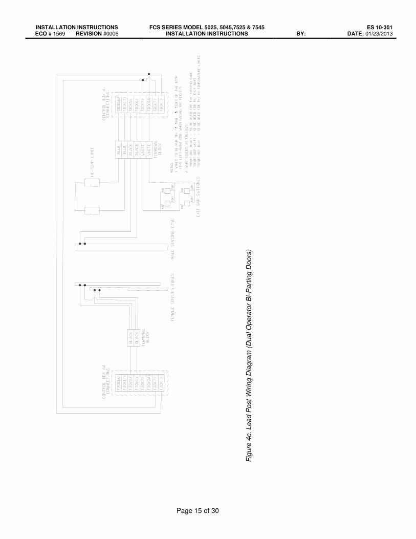
B. Procedure
1. Do not run control wiring in the same conduit as power wiring. 2. After installation, be sure that the operator, controls, and sensing edge or other entrapment
protection devices have been tested and function properly. 3. Refer to
Single-Slide doors: Figure 4a. Bi-Part Single Operator: Figure 4b. Bi-Part Dual Operator: Figure 4c.

INSTALLATION INSTRUCTIONS FCS SERIES MODEL 5025, 5045,7525 & 7545 INSTALLATION INSTRUCTIONS
ES 10-301 ECO # 1569 REVISION #0006 BY: DATE: 01/23/2013
Page 14 of 30
Figure 4a. Lead Post Wiring Diagram (Single-Slide Doors)
Figure 4b. Lead Post Wiring Diagram (Single Operator Bi-Parting Doors)
:“ “ “ “:ON LEAD MEMBER
:“ “ “ “:ON LEAD MEMBER
INSTALLATION INSTRUCTIONS FCS SERIES MODEL 5025, 5045,7525 & 7545 INSTALLATION INSTRUCTIONS
ES 10-301 ECO # 1569 REVISION #0006 BY: DATE: 01/23/2013
Page 15 of 30
: ? ? ? ? :
Fig
ure
4c. Le
ad P
ost
Wir
ing D
iagra
m (
Dua
l O
pera
tor
Bi-P
art
ing D
oors
)

INSTALLATION INSTRUCTIONS FCS SERIES MODEL 5025, 5045,7525 & 7545 INSTALLATION INSTRUCTIONS
ES 10-301 ECO # 1569 REVISION #0006 BY: DATE: 01/23/2013
Page 16 of 30
5. Check List
� Make sure all wires are connected, supply power is OFF, disconnect the battery wires.
� Make sure Alarm Wires are connected.
• TB3 termination 11 & 12 normally closed for dry contact.
• Set Open and Close limits and position the door at the close limit before connecting alarm wires.
� Jump High Limit connection, TB3 (16 & 17).
� Adjust Emergency Opening Distance (if required) � Standard door speed is 9 inches per second. � Timer setup to increases opening travel. Adds 9” of egress opening for each second on the timer. � Factory Default: Approximately 54”. � Refer to Section 13. Function and timer set-up (5) Egress Exit Open timer on page 27.
� Check that Battery wires are connected and correct. � Connect 120VAC main power.

INSTALLATION INSTRUCTIONS FCS SERIES MODEL 5025, 5045,7525 & 7545 INSTALLATION INSTRUCTIONS
ES 10-301 ECO # 1569 REVISION #0006 BY: DATE: 01/23/2013
Page 17 of 30
6. Wiring Diagram

INSTALLATION INSTRUCTIONS FCS SERIES MODEL 5025, 5045,7525 & 7545 INSTALLATION INSTRUCTIONS
ES 10-301 ECO # 1569 REVISION #0006 BY: DATE: 01/23/2013
Page 18 of 30

INSTALLATION INSTRUCTIONS FCS SERIES MODEL 5025, 5045,7525 & 7545 INSTALLATION INSTRUCTIONS
ES 10-301 ECO # 1569 REVISION #0006 BY: DATE: 01/23/2013
Page 19 of 30

INSTALLATION INSTRUCTIONS FCS SERIES MODEL 5025, 5045,7525 & 7545 INSTALLATION INSTRUCTIONS
ES 10-301 ECO # 1569 REVISION #0006 BY: DATE: 01/23/2013
Page 20 of 30
Figure 6.a. Model FCS Wiring Diagram

INSTALLATION INSTRUCTIONS FCS SERIES MODEL 5025, 5045,7525 & 7545 INSTALLATION INSTRUCTIONS
ES 10-301 ECO # 1569 REVISION #0006 BY: DATE: 01/23/2013
Page 21 of 30
7
. F
ield
Wir
ing
Te
rmin
al
Str
ip C
on
ne
cti
on
s
TB
2
50
-
Pow
er
Outp
ut
24V
DC
/1A
Max.
Pow
er
outp
ut
when
Ala
rm
conditio
n.
49
+
48
Hig
h T
em
p o
r A
larm
or
Overload d
ry
conta
ct,
24V
AC
/DC
, 0.5
A
Max.
Conta
ct
ope
n
when a
bn
orm
al.
TB
3
17
Hig
h lim
it
(Jum
p w
hen
not con
necte
d
to h
igh lim
it).
No
te:
1.
Whe
n u
sin
g K
ey S
witch
without
a s
top
butt
on,
term
ina
ls 1
& 4
shou
ld b
e jum
pe
d a
nd O
NLY
sele
ct consta
nt pre
ssure
clo
se a
nd o
pen.
2.
CN
7 F
orc
e O
pen W
arn
ing
Dry
Conta
ct –
conta
ct po
ints
will
be
op
ene
d w
hen d
oor
was p
ush
ed a
way fro
m c
lose lim
it
and f
aile
d to r
each c
lose
lim
it p
ositio
n w
ithin
5 s
eco
nd
s.
47
16
46
Charg
e w
arn
ing
dry
conta
ct,
24V
AC
/DC
, 0.5
A
Max.
Conta
ct
ope
n
when a
bn
orm
al.
12
Dry
conta
ct
Ala
rm
connection.
45
11
44
LH
-Clo
se
lim
it
RH
-Open lim
it
dry
conta
ct,
24V
AC
/DC
,
0.5
A M
ax.
C
onta
ct
ope
n
when d
oor
reaches lim
it.
Egre
ss b
ar
co
nnections.
43
7
42
LH
-Open lim
it
RH
-Clo
se lim
it
dry
conta
ct,
24V
AC
/DC
,
0.5
A M
ax.
C
onta
ct
ope
n
when d
oor
reaches lim
it.
8A
41
7
40
Batt
ery
volta
ge
warn
ing d
ry
conta
ct,
24V
AC
/DC
,
0.5
A M
ax.
C
onta
ct
ope
n
when a
bn
orm
al.
6
Sensin
g e
dg
e
connection N
/O.
(End o
f lin
e
resis
tor)
39
5
38
Overload
warn
ing d
ry
conta
ct,
24V
AC
/DC
,
0.5
A M
ax.
C
onta
ct
ope
n
when a
bn
orm
al.
4
Contr
ol S
tation K
ey S
witch
or
3-b
utto
n c
ontr
ol sta
tio
n Com
37
3
Clo
se
36
AC
pow
er
warn
ing d
ry
conta
ct,
24V
AC
/DC
,
0.5
A M
ax.
C
onta
ct
ope
n
when a
bn
orm
al
2
Open
35
1
Sto
p

INSTALLATION INSTRUCTIONS FCS SERIES MODEL 5025, 5045,7525 & 7545 INSTALLATION INSTRUCTIONS
ES 10-301 ECO # 1569 REVISION #0006 BY: DATE: 01/23/2013
Page 22 of 30
8. Functions Table
Item Function Normal Condition Alarm Condition
1 Control Station TB3 (1,2,3,4) Constant Pressure OPEN and CLOSE
Door will CLOSE. Constant pressure OPEN but auto closing.
2 Sensing Edge TB3 (5 & 6) (See section 13, (13) and (14)
� 3 Sec. reverse and then stop
� Sensing edge will reverse door travel for 3 seconds and then door will close again. If the obstruction is not removed, the door will stop on the obstruction on the 3
rd closing
� Sensing Edge can be inactive during the initial closing. This inactive distance can be adjusted.
� Sensing Edge is inactive during last few inches of door closing. This inactive distance can be adjusted.
� When Sensing Edge is engaged, Exit Hardware and push button station will be active.
3
Exit Direction [(Exit Bar Connection TB3 (7, 8A or (blank)] (Only label 7 & 8 A, and a blank)
All exit bars are functional.
� Exit direction will dictate which exit bar will be functional.
� 7 & 8A-active during both normal and alarm condition.
� 7 & (blank) -active only during normal condition, not alarm condition.
4 High Temperature Limit TB3 (16 & 17)
No effect of the door operation.
All three conditions have to be met to disable the opening function of the door: alarm condition, door close condition, and high limit break.
5
Clutch Always Engage at Opening setting (Logic setting) (See Section 13, (11))
Select (NO) to disengage clutch when door is in the open position. This can prolong battery life during power failure.
6
Fire door selection (S106) (F.D. & E.D. Switch) (E.D. Selected) FD – Fire Door without Exit Bar ED – Fire Door with Exit Bar
No effect on regular operation of the door.
� If selected (F.D.), no exit bar will be functional. When door reaches close limit, all control function will cease per NFPA 80 2007. Control function is back to normal only after alarm condition has been cleared.
� If E. D. selected.), exit bar will be functional.
7 Battery Warning Closing (S104) (Stay Open & Close 2 Feet Switch)
� If selected (Close 2 Feet), when door is in the open limit position, it will automatically CLOSE 24 inches during battery low. This is to notify the user that the battery needs to be checked. This is in addition to normal sound and signal outputs. The clutch will be disengaged when the door is in the closed 2’ position due to the low battery.
� If selected (Stay Open), normal sound and signal outputs will apply. Battery Needs to be checked
Battery Low sound and signal outputs continue to happen after the door has closed during alarm. Clutch will be engaged during alarm condition.

INSTALLATION INSTRUCTIONS FCS SERIES MODEL 5025, 5045,7525 & 7545 INSTALLATION INSTRUCTIONS
ES 10-301 ECO # 1569 REVISION #0006 BY: DATE: 01/23/2013
Page 23 of 30
Functions Table (Continued)
Item Function Normal Condition Alarm Condition
8
Exit Bar Setting (S105) (Switch: ON Setting) (Logic setting) (See Section 13, (6))
� If selected (ON), door will OPEN to preset distance, pause and then CLOSE. Pause time can be adjusted between 3 - 99 seconds via Logic Setting.
� If not selected (OFF), door will OPEN to preset time/distance and stop.
Door will OPEN to preset distance, pause and then CLOSE. Pause time is the same as normal condition.
9
Exit Bar Opening (6-99 seconds). (Logic Setting) (See Section 13, (5))
Can increase the opening time/distance of Exit Bar. Minimum time is 6 seconds, which will provide approximately 54 inches of opening. Maximum distance is to open limit. Factory default is 6 seconds.
10
Security Door Option (Switch: E.D. Mode) Security Mode : select Yes (Logic setting) (See Section 13, (3))
Exit Bar will not be functional. Door can only be opened or closed via push-button control station or key switch.
Exit Bar will be functional.
11
Security Door Power Loss of AC Power (Switch: E.D. Mode) Auto Close : select Yes In Security Mode (See Section 13, (4))
� If both Security Door Option and Security Door Power are selected (YES), door will automatically CLOSE during power failure and Exit Bar will be functional.
� If selected (NO), then only Security Door Option is active. Door will not CLOSE during power failure.
Door will auto CLOSE due to alarm and Exit Bar will be active.
12
Alarm Delay Time (Logic setting) (See Section 13, (7))
No effect on normal operation. � Select 0~10 second delay, but alarm warning power/signal is present as soon as alarm condition happens. This allows pre-warning before door starts closing.
13 Clock (Logic setting) (See Section 13, (8))
No effect in operation.
14
Battery load test time and setting (Logic setting) (See Section 13, (9))
Not necessary to specify. If a specific time is needed, need to set clock.
15 Alarm Restore Auto Open (Logic setting) (See Section 13, (12))
No affect in operation. � When alarm clears door will auto open.

INSTALLATION INSTRUCTIONS FCS SERIES MODEL 5025, 5045,7525 & 7545 INSTALLATION INSTRUCTIONS
ES 10-301 ECO # 1569 REVISION #0006 BY: DATE: 01/23/2013
Page 24 of 30
9. Output Warnings
Item Terminals Description Contact Type
1 35 & 36 AC Power Warning Dry Contact
2 37 & 38 Overload Warning Dry Contact
3 39 & 40 Battery Voltage Warning Dry Contact
4 41 & 42 LH-Open Limit RH-Close Limit
Dry Contact
5 43 & 44 LH-Close Limit RH-Open Limit
Dry Contact
6 45 & 46 Charge Warning Dry Contact
7 47 & 48 High Temp or
Alarm or Overload
Dry Contact
8 49 & 50 Power Output 24VDC
9 CN7 Warning Output Dry Contact
10. Sound Warnings
Item Description Sound
A AC power loss warning signal B_____ B.B. B_____ B.B. B_____ B.B. ….
B Overload warning signal B_____ B. B_____ B. B_____ B. ……
C Battery failure warning signal B_____ B.B.B. B_____ B.B.B. B_____ B.B.B. ….
D Alarm warning signal or high temperature
B_____ B_____ B_____ B_____ ……
E T1,4 not connected or control panel cover opened
B.B.B.B. B.B.B.B. B.B.B.B. ….
INSTALLATION INSTRUCTIONS FCS SERIES MODEL 5025, 5045,7525 & 7545 INSTALLATION INSTRUCTIONS
ES 10-301 ECO # 1569 REVISION #0006 BY: DATE: 01/23/2013
Page 25 of 30
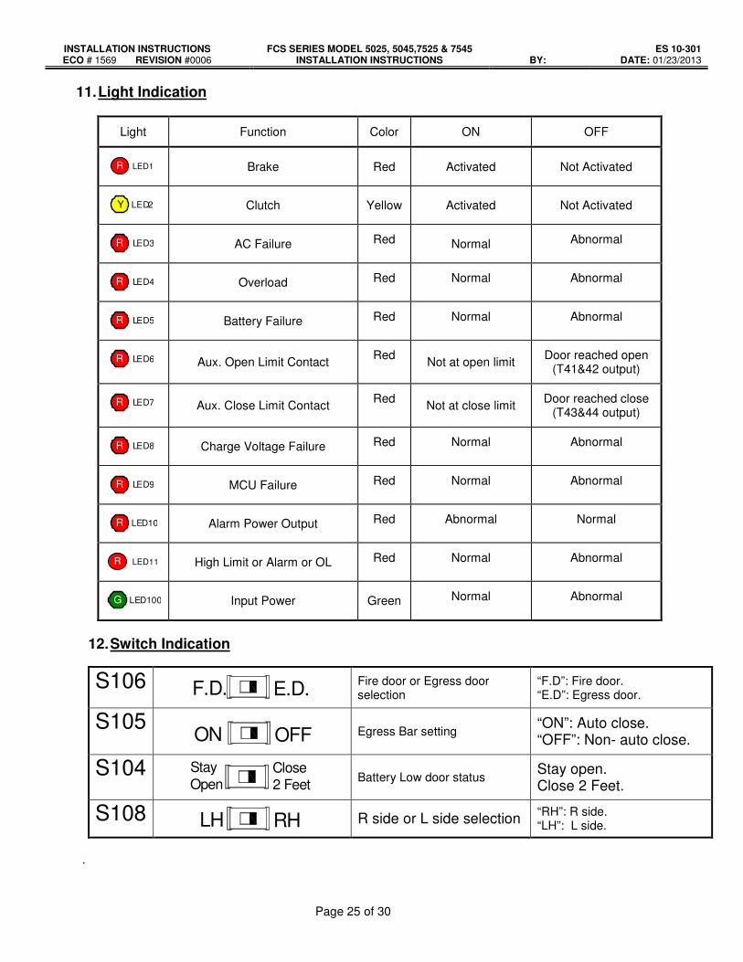
11. Light Indication
Light Function Color ON OFF
R LED1
Brake Red Activated Not Activated
Y LED2
Clutch Yellow Activated Not Activated
R LED3
AC Failure Red Normal Abnormal
R LED4
Overload Red Normal Abnormal
R LED5
Battery Failure Red Normal Abnormal
R LED6 Aux. Open Limit Contact
Red Not at open limit
Door reached open (T41&42 output)
R LED7 Aux. Close Limit Contact
Red Not at close limit
Door reached close (T43&44 output)
R LED8
Charge Voltage Failure Red Normal Abnormal
R LED9
MCU Failure Red Normal Abnormal
R LED10
Alarm Power Output Red Abnormal Normal
R LED11
High Limit or Alarm or OL Red Normal Abnormal
G LED100
Input Power Green Normal Abnormal
12. Switch Indication
S106 F.D. E.D. Fire door or Egress door selection
“F.D”: Fire door. “E.D”: Egress door.
S105 ON OFF Egress Bar setting
“ON”: Auto close. “OFF”: Non- auto close.
S104 Stay
OpenClose2 Feet Battery Low door status
Stay open. Close 2 Feet.
S108 LH RH R side or L side selection “RH”: R side. “LH”: L side.
.

INSTALLATION INSTRUCTIONS FCS SERIES MODEL 5025, 5045,7525 & 7545 INSTALLATION INSTRUCTIONS
ES 10-301 ECO # 1569 REVISION #0006 BY: DATE: 01/23/2013
Page 26 of 30
13. Function and Timer Set-Up Instructions
(1) Standby Mode:
(2) Constant/Momentary pressure setting of OPEN/CLOSE Button � Press “SET” for three seconds to enter setting mode. Use “SELECT” to choose “Constant
Pressure”. Use “+” and “-” to Constant Pressure or Momentary Pressure. Press “SET” again to save setting. “SAVE SUCCESS” will appear if setting is complete.
(3) Security Mode setting in Exit Door Mode � Switch to E.D. Mode, Press “SET” for three seconds to enter setting mode. Use “SELECT” to
choose “Security Mode”. Use “+” and “-” to Yes or No. Press “SET” again to save setting. “SAVE SUCCESS” will appear if setting is complete.
� Attention: “F.D.” mode is not for security mode setting.
(4) Door Close setting in AC Power loss � Switch to E.D. Mode, Press “SET” for three seconds to enter setting mode. Use “SELECT” to
choose “Loss of AC Power Auto close”. Use “+” and “-” to Yes or No. Press “SET” again to save setting. “SAVE SUCCESS” will appear if setting is complete.
� Attention: “F.D.” mode is not for door close setting in AC Power loss.
AC Power Counter
Battery Power Current Time
AC 000V DC 00.0V CNT: 0000056 00:06
Security Mode Select:Yes
Security Mode SAVE SUCCESS!!
Complete
Complete >Constant Pressure
Momentary Pressure
Constant Pressure SAVE SUCCESS!!
Complete Constant Pressure >Momentary Pressure
Momentary Pressure SAVE SUCCESS!!
Choose
Loss of AC Power Auto Close:Yes
Loss of AC Power SAVE SUCCESS!!
Complete

INSTALLATION INSTRUCTIONS FCS SERIES MODEL 5025, 5045,7525 & 7545 INSTALLATION INSTRUCTIONS
ES 10-301 ECO # 1569 REVISION #0006 BY: DATE: 01/23/2013
Page 27 of 30
(5) Egress Exit Open timer � Press “SET” for three seconds to enter setting mode. Use “SELECT” to choose “Egress open
time”. Use “+” and “-” to set time: 06~99, 06 being the minimum time for 54 inches of opening. Press “SET” again to save setting. “SAVE SUCCESS” will appear if setting is complete.
(6) Egress Pause Timer: � Press “SET” for three seconds to enter setting mode. Use “SELECT” to choose “Egress pause
close”. Use “+” and “-” to set time: 03~99, 03 being the minimum time for egress pause close. Press “SET” again to save setting. “SAVE SUCCESS” will appear if setting is complete.
(7) Alarm Delay Time � Press “SET” for three seconds to enter setting mode. Use “SELECT” to choose “Alarm delay
time”. Use “+” and “-” to set time: 00~10, 00 being disabled. Press “SET” again to save setting. “SAVE SUCCESS” will appear if setting is complete.
(8) Clock � Press “SET” for three seconds to enter setting mode. Use “SELECT” to choose “Clock-Set time”.
Use “+” and “-” to set hour. (00~24 hour) � Press “SELECT” again to set minute. Use “+” and “-” to set minute. (00~59 minutes) � Press “SET” again to save setting. “SAVE SUCCESS” will appear if setting is complete.
Complete Egress open time:06
(06→99) 00: NO use
Egress open time:06
SAVE SUCCESS!!
Complete
Egress pause close:03
(03→99) 00: NO use
Egress pause close:03
SAVE SUCCESS!!
Complete Alarm delay time:00
(00→10) 00:NO use
Alarm delay time:00
SAVE SUCCESS!!
Complete
Clock-Set time 10:00 HOUR(00→23) :10
Clock-Set time 10:10 MINUTE(00→59):10
Clock-Set time 10:10 SAVE SUCCESS!!

INSTALLATION INSTRUCTIONS FCS SERIES MODEL 5025, 5045,7525 & 7545 INSTALLATION INSTRUCTIONS
ES 10-301 ECO # 1569 REVISION #0006 BY: DATE: 01/23/2013
Page 28 of 30
(9) Battery load test time and setting: (Every 24 hours and 10 second of load test.)
� Press “SET” for three seconds to enter setting. Use “SELECT” to choose “Battery test time”. Use “+” and “-” to set hour. (00~23 Hours)
� Press “SET” again to save setting. “SAVE SUCCESS” will appear if setting is complete.
(10) Loss AC Warning � Press “SET” for three seconds to enter setting mode. Use “SELECT” to choose “Loss AC delay”.
Use “+” and “-” to set time: 00~180 minutes, 00 being disabled. Press “SET” again to save setting. “SAVE SUCCESS” will appear if setting is complete.
(11) Clutch Always Engage At Opening setting � Press “SET” for three seconds to enter setting mode. Use “SELECT” to choose “Clutch Always
Engage At Opening”. Use “+” and “-” to set time: YES or NO. Press “SET” again to save setting. “SAVE SUCCESS” will appear if setting is complete.
(12) Alarm Restore Auto Open � Press “SET” for three seconds to enter setting mode. Use “SELECT” to choose “Alm
Restore AutoOpen”. Use “+” and “-” to set Yes or No. Press “SET” again to save setting. “SAVE SUCCESS” will appear if setting is complete.
Complete Battery test time
HOUR(00→23):23 Battery test time
SAVE SUCCESS!!
Complete Loss AC delay:000
(00→180) 00:NO Delay
Loss AC delay:000
SAVE SUCCESS!!
Complete Clutch Always Engage At Opening : Yes
Clutch Always Engage SAVE SUCCESS!!
Complete Alm Restore AutoOpen (Yes or No) : Yes
Alm Restore AutoOpen SAVE SUCCESS!!

INSTALLATION INSTRUCTIONS FCS SERIES MODEL 5025, 5045,7525 & 7545 INSTALLATION INSTRUCTIONS
ES 10-301 ECO # 1569 REVISION #0006 BY: DATE: 01/23/2013
Page 29 of 30
(13) SE OFF Delay – Sensing edge disable delay when LS4 engaged � Press “SET” for three seconds to enter setting mode. Use “SELECT” to choose “SE OFF Delay”.
Use “+” and “-” to set time: 0~5 seconds for SE OFF Delay from LS4 engaged. Press “SET” again to save setting. “SAVE SUCCESS” will appear if setting is complete.
(14) SE ON Delay – Sensing edge enable delay when LS3 disengaged � Press “SET” for three seconds to enter setting mode. Use “SELECT” to choose “SE ON Delay”.
Use “+” and “-” to set time: 0~5 seconds for SE ON Delay from LS3 disengaged. Press “SET” again to save setting. “SAVE SUCCESS” will appear if setting is complete.
(15) Alarm Warning Sound � Press “SET” for three seconds to enter setting mode. Use “SELECT” to choose “Alarm Warning
Sound”. Use “+” and “-” to set Yes or No. Press “SET” again to save setting. “SAVE SUCCESS” will appear if setting is complete.
(16) High TEMP Sound � Press “SET” for three seconds to enter setting mode. Use “SELECT” to choose “High TEMP
Sound”. Use “+” and “-” to set Yes or No. Press “SET” again to save setting. “SAVE SUCCESS” will appear if setting is complete.
Complete SE OFF Delay (0→5) sec: 0.0
SE OFF Delay SAVE SUCCESS!!
Complete SE ON Delay (0→5) sec: 0.0
SE ON Delay SAVE SUCCESS!!
Complete Alarm Warning Sound (Yes or No) : No
Alarm Warning Sound SAVE SUCCESS!!
Complete High TEMP Sound (Yes or No) : Yes
High TEMP Sound SAVE SUCCESS!!
INSTALLATION INSTRUCTIONS FCS SERIES MODEL 5025, 5045,7525 & 7545 INSTALLATION INSTRUCTIONS
ES 10-301 ECO # 1569 REVISION #0006 BY: DATE: 01/23/2013
Page 30 of 30
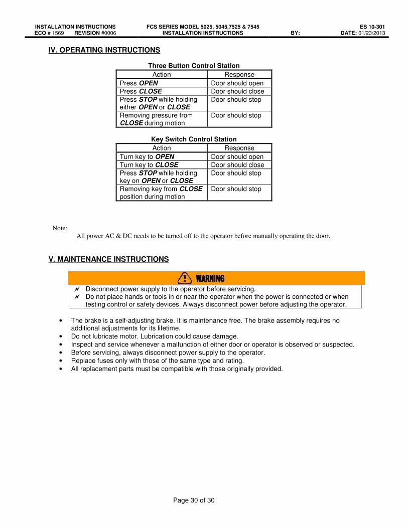
IV. OPERATING INSTRUCTIONS
Three Button Control Station
Action Response
Press OPEN Door should open
Press CLOSE Door should close
Press STOP while holding either OPEN or CLOSE
Door should stop
Removing pressure from CLOSE during motion
Door should stop
Key Switch Control Station
Action Response
Turn key to OPEN Door should open
Turn key to CLOSE Door should close
Press STOP while holding key on OPEN or CLOSE
Door should stop
Removing key from CLOSE position during motion
Door should stop
Note:
All power AC & DC needs to be turned off to the operator before manually operating the door.
V. MAINTENANCE INSTRUCTIONS
� Disconnect power supply to the operator before servicing. � Do not place hands or tools in or near the operator when the power is connected or when
testing control or safety devices. Always disconnect power before adjusting the operator.
• The brake is a self-adjusting brake. It is maintenance free. The brake assembly requires no additional adjustments for its lifetime.
• Do not lubricate motor. Lubrication could cause damage.
• Inspect and service whenever a malfunction of either door or operator is observed or suspected.
• Before servicing, always disconnect power supply to the operator.
• Replace fuses only with those of the same type and rating.
• All replacement parts must be compatible with those originally provided.