installation guidelines vme swinglift cranes … rev 1... · test weights ... • the finished...
TRANSCRIPT

Penny Hydraulics Ltd Installation Guidelines – VME - SwingLift Cranes – ML Range
PH_VME_II_002 Revision 1 Page 1 of 42
INSTALLATION GUIDELINES VME – SwingLift Cranes – ML Range
PH_VME_II_002 Rev 1

Penny Hydraulics Ltd Installation Guidelines – VME - SwingLift Cranes – ML Range
PH_VME_II_002 Revision 1 Page 2 of 42
Contents
Introduction ................................................................................................................................ 5
General Safety Guidelines ................................................................................................................... 6
Legislation ........................................................................................................................................... 8
The Health and Safety at Work Act 1974 ....................................................................................................... 8
(LOLER) Lifting Operation and Lifting Equipment Regulations 1998.............................................................. 8
The Provision and Use of Work Equipment Regulations 1992 (PUWER) ....................................................... 8
Section 9 - Training ........................................................................................................................................ 8
The Supply of Machinery (Safety) Regulations 1992 – Machinery Directive ................................................. 9
British BS, European EN and International ISO Standards ............................................................................. 9
BS 7121 Safe Use of Cranes, Parts 2 and 4 ................................................................................................ 9
BS EN 12999 Cranes – Loader Cranes ........................................................................................................ 9
ALLMI Code of Practice for Installation Application and Operation .............................................................. 9
Range Overview ................................................................................................................................ 10
SwingLift ML250 – Short or long boom ........................................................................................................ 10
Dimensional Drawing .............................................................................................................................. 10
Picking List ............................................................................................................................................... 10
SwingLift ML500 – Short or long boom ........................................................................................................ 11
Dimensional Drawing – Short Boom ........................................................................................................ 11
Dimensional Drawing – Long Boom......................................................................................................... 11
Picking List ............................................................................................................................................... 12
Planning the Installation ............................................................................................................ 13
Introduction ...................................................................................................................................... 13
Checks prior to installation ............................................................................................................... 13
Stability ............................................................................................................................................. 13
Stability Calculations - Example ........................................................................................................ 14
Installation - Mechanical ............................................................................................................ 15
General rules ..................................................................................................................................... 15
Van Type Installations ....................................................................................................................... 16
Pick-Up Type Installations ................................................................................................................. 17
Installation – Electrical ............................................................................................................... 18
Typical Wiring Layout ........................................................................................................................ 19
Installation Technical Files .......................................................................................................... 20
Who the guidance is aimed at .......................................................................................................... 20
What the law says ............................................................................................................................. 20

Penny Hydraulics Ltd Installation Guidelines – VME - SwingLift Cranes – ML Range
PH_VME_II_002 Revision 1 Page 3 of 42
Technical file contents guidance ....................................................................................................... 20
Commissioning documents ............................................................................................................... 21
Vehicle manufacturer recommendations ......................................................................................... 21
Electrical drawings ............................................................................................................................ 21
Photographs ...................................................................................................................................... 21
Vehicle collection/handover documents .......................................................................................... 21
Axle loading & stability calculations ................................................................................................. 21
Whole Vehicle Type Approval ........................................................................................................... 22
Thorough Examination ............................................................................................................... 23
BS7121 Part 2 .................................................................................................................................... 23
Visual Inspection ........................................................................................................................ 24
Function Check .......................................................................................................................... 24
Crane support legs ............................................................................................................................ 24
Hoist (if fitted) ................................................................................................................................... 24
Running In ......................................................................................................................................... 24
Calibration Check ....................................................................................................................... 25
Test weights ...................................................................................................................................... 25
Dynamic Test ............................................................................................................................. 25
Overload Test ............................................................................................................................ 26
Introduction ...................................................................................................................................... 26
How to override the overload protection ......................................................................................... 26
Performing the overload test ............................................................................................................ 26
1st & 2nd Visual Inspection ........................................................................................................... 27
Final Checklist ............................................................................................................................ 27
Preparing & Issuing a Report of Thorough Examination & Test .................................................... 27
Appendix ................................................................................................................................... 28
Spare Parts List .................................................................................................................................. 28
ML250– Exploded View................................................................................................................................ 28
ML250 – Parts List ........................................................................................................................................ 29
ML500 – Exploded View ............................................................................................................................... 31
ML500 – Parts List ........................................................................................................................................ 32
Lorry Loader Servicing ....................................................................................................................... 33
Equipment Register for Penny Hydraulics Limited Service Contract ........................................................... 34
Credit Account Application .......................................................................................................................... 35
Penny Hydraulics Ltd Standard Terms and Conditions (for the Supply of Goods and Services to
non-consumers) ................................................................................................................................ 36

Penny Hydraulics Ltd Installation Guidelines – VME - SwingLift Cranes – ML Range
PH_VME_II_002 Revision 1 Page 4 of 42
1 Interpretation ...................................................................................................................................... 36
2 Basis of Contract ................................................................................................................................. 36
3 Goods .................................................................................................................................................. 37
4 Delivery ............................................................................................................................................... 37
5 Quality ................................................................................................................................................. 37
6 Title and Risk ....................................................................................................................................... 38
7 Price and Payment .............................................................................................................................. 39
8 Customer’s Insolvency or Incapacity ................................................................................................... 40
9 Limitation of Liability ........................................................................................................................... 41
10 Force Majeure ..................................................................................................................................... 41
11 General ................................................................................................................................................ 41

Penny Hydraulics Ltd Installation Guidelines – VME - SwingLift Cranes – ML Range
PH_VME_II_002 Revision 1 Page 5 of 42
Introduction
Thank you for purchasing a Penny Hydraulics SwingLift ML (Mini Loader) crane. The SwingLift Mini Loader is a vehicle mounted crane designed and manufactured at our factory in Clowne, Chesterfield to safely lift and position loads of up to 500kg. The crane is operated remotely from a handheld pendant control with all functions being protected by inbuilt overload features and is powered by the vehicle battery. These general installation guidelines tell you the correct and safe method of installing this product in various positions within several types of commercial vehicles. For fitting guidelines pertaining to a specific vehicle model, please refer to the vehicle specific instruction manual provided. If in doubt, do not hesitate to contact Penny Hydraulics Ltd directly for more information on vehicle specific instructions.
Winch Assembly
Cranked Hinge
Corner Bracket
Combi Pillar (van/pickup Type)
Manual
Support Leg
Remote Control (3 button handset)
Winch Rope Assembly
Crane Section Only
Drop Down
Support Leg
Support Leg
Extension
Pillar (vehicle specific)
Top Bracket (vehicle specific)
½ Bob Weight (to increase lift)
Rope Hook (Bulkhead Mount)

Penny Hydraulics Ltd Installation Guidelines – VME - SwingLift Cranes – ML Range
PH_VME_II_002 Revision 1 Page 6 of 42
General Safety Guidelines For optimum safety and to keep your Penny Hydraulics SwingLift in good working order, follow these simple Dos and Don’ts.
Do not exceed the Maximum Working Load Your Penny Hydraulics lifting equipment is clearly marked with the MWL (Maximum Working Load). Do not drag or tow To avoid damage to the SwingLift and mounting points, it must be used only for lifting. Do not expose the red section of rope This section is marked to alert the user that they are approaching the full extent of the rope and should not proceed further. Do not wrap the rope around the load This will cause excessive chafing and splintering of the rope. Appropriate lifting accessories should be used instead. Rope must not spool from top of winch If your wire rope is spooling from the top of your winch, the rope is wound incorrectly on the drum. The SwingLift must not be used until this is rectified. Do not leave a load suspended Never leave a load suspended or unattended. Always use the rope hook to stow the crane The rope hook is one of several methods used to secure the crane for transit. If supplied, always use the stabiliser leg Not every Penny Hydraulics SwingLift is supplied with a support leg but when this is supplied, it must be used. Always stow the crane before driving To avoid damage to the SwingLift, vehicle and surroundings, the crane must be stowed correctly before driving.
• It would be expected that the installer would have access to the chassis manufacturers body builder guidelines and installation guidelines from the crane manufacturer.
• The installer would be expected to work within a quality procedure, use coded welders and have traceability of materials, where necessary.
• The finished loader crane installation must be subject to a thorough examination and test for which calibrated weights are required, a test area and a competent person to conduct the examination and test.
• The competent person may be an in-house employee or an independent engineer but in all cases sufficiently independent and impartial to allow objective decisions to be made.
• The competent person will have adequate knowledge of the equipment.
• Check that this is the correct instruction manual for the crane being fitted

Penny Hydraulics Ltd Installation Guidelines – VME - SwingLift Cranes – ML Range
PH_VME_II_002 Revision 1 Page 7 of 42
• Check that no damage has occurred to the component parts in transit
• Check that all system components are present against the assembly parts list (section 1.1).
• Check that crane type is suitable for the intended application
• Check that vehicle and crane voltage is the same, i.e. 12V or 24V
• Carry out Stability Calculations, where necessary (see section 3.3)
• An effective and safe lorry loader will be one in which the vehicle and loader crane are well matched in respect of type and dimensions of load to be handled.
• A lorry loader must meet the legal requirements for a road-going vehicle, axle loads and overall dimensions etc.
• Considerations must be given to the lifting capacity, radius, height & depth of lift and reach.
• Consideration should also be given to the vehicle in relation to its GVW (Gross Vehicle Weight), stability, and chassis strength, maintenance and general serviceability.
• The remaining payload of the chassis, once a loader crane is installed should be considered.
• The space required for proper deployment of stabilisers should be considered.
• Where supplied, stabiliser legs must always be used.
• Ensure the crane and stabiliser legs are securely stowed before travel.
• Ensure that the crane has 2 methods of stowage.

Penny Hydraulics Ltd Installation Guidelines – VME - SwingLift Cranes – ML Range
PH_VME_II_002 Revision 1 Page 8 of 42
Legislation It is important that the chosen installer of this equipment is suitably competent and abides by current
legislation and guidance with regards to the installation of vehicle-mounted lifting equipment. There are many
regulations that a Lorry Loader should adhere to from manufacture, installation, through to the safe operation
of the equipment once it has been fitted to a vehicle.
All following references to legislation and standards are correct at the time of writing, but you are advised to
check that they are current when planning your installation.
The Health and Safety at Work Act 1974
Under Section 3 of the Health and Safety at Work Act the prime duty of care rests with the employer, but employees have legal duties too, particularly under Sections 7 and 8 of the Act. These include:
• Taking reasonable care of their own Health & Safety and that of others who may be affected by what they do or don't do.
• Co-operating with their employer on Health & Safety matters.
• Not interfering with or misusing anything provided for their health, safety and welfare.
The Health and Safety at Work Act will also be used by the enforcing authority as it requires, in general terms, that the safety of all persons is, so far as is reasonably practicable, ensured at all times.
(LOLER) Lifting Operation and Lifting Equipment Regulations 1998
LOLER was brought about in 1998 to sit alongside the Health & Safety at Work Act 1974, Supply of Machinery Regulations 1992 and the Provision and Use of Work Equipment Regulations 1998. The Regulations impose health and safety requirements with respect to lifting equipment. Previously, all of these Acts had their own schedule of legal requirements for the testing and examination of lifting equipment. LOLER sought to harmonise best practice from all previous acts and replace them with one document. More detail again is available in the Approved Code of Practice associated with LOLER.
The Provision and Use of Work Equipment Regulations 1992 (PUWER)
PUWER is a broad-based set of regulations with responsibilities for purchasers and operators. Any person who buys equipment must ensure that it is suitable for its intended use. They must also ensure that it is properly maintained, regularly inspected and the information logged. PUWER also determines any specific risks and details what information and instructions must be made available to operators.
Section 9 - Training
9.1 Every employer shall ensure that all persons who use work equipment have received adequate training for purposes of health and safety, including training in the methods which may be adopted when using the work equipment, any risks which such use may entail and precautions to be taken.
9.2 Every employer shall ensure that any of his employees who supervises or manages the use of work equipment has received adequate training for purposes of health and safety, including training in the methods which may be adopted when using the work equipment, any risks which such use may entail and precautions to be taken.

Penny Hydraulics Ltd Installation Guidelines – VME - SwingLift Cranes – ML Range
PH_VME_II_002 Revision 1 Page 9 of 42
The Supply of Machinery (Safety) Regulations 1992 – Machinery Directive
Manufacturers have a high degree of responsibility to produce information for operators as part of the CE marking process. This takes the form of producing operating manuals, description of the intended use, service schedules and inspection regimes. Sticking to these regimes will ensure that they meet their obligations as an operator. They must be aware though that if there has been a significant change, accident or a major new component fitted to a lifting machine then a further thorough examination and load test may be required. The Supply of Machinery (Safety) Regulations 1992, also called the Machinery Directive, contains the essential health and safety criteria that all machines must meet. There are responsibilities for designers, manufacturers and suppliers. The manufacturer must have developed a “technical file” that is a legal requirement and it documents how they meet the criteria. Having documented how they meet the criteria, they can fix the CE mark to the machine and release a “Declaration of Conformity”.
British BS, European EN and International ISO Standards
Standards do not generally have the force of law; the application of a standard is almost always voluntary, although standards are very often used in support of the legislation, and compliance with a standard is sometimes quoted in legislation as offering a route to discharging legal obligations. Good examples of this are references to BS7121 in the Guidance to LOLER.
Note: British Standards (BS) are generally restricted to Codes of Practice for safe use of equipment e.g. BS7121-4 Safe Use of Lorry Loaders.
BS 7121 Safe Use of Cranes, Parts 2 and 4
BS EN 12999 Cranes – Loader Cranes European (EN) standards cover requirements for basic principles - (Type A), Common product requirements - (Type B) Specific product requirements - (Type C) e.g. EN12999 Cranes – Loader Cranes. Harmonised European Standards, which give presumption of conformity to the Essential Health and Safety Requirements of the Machinery Directive. International Standards (ISO) cover both the safe use and specification of cranes and components. They do not have any legal status but are often taken as good practice and are stated as normative references in some EN product standards.
ALLMI Code of Practice for Installation Application and Operation
The Association of Lorry Loader Manufacturers and Importers (ALLMI) was founded in 1978 at the request of the Health and Safety Executive, and it remains today as the UK’s only Trade Association devoted exclusively to the lorry loader industry. It serves, represents and promotes the interests of its members and the industry at large, and it is the natural focus and authority on all issues involving the design, manufacture, application and use of lorry loaders.

Penny Hydraulics Ltd Installation Guidelines – VME - SwingLift Cranes – ML Range
PH_VME_II_002 Revision 1 Page 10 of 42
Range Overview The Mini Loader range of cranes consists of two basic models:
SwingLift ML250 – Short or long boom
A compact, lightweight, demountable crane for pickups, box bodies and vans. 250KG maximum capacity with an 824-882mm boom extension allowing lifts within a 1648-1764mm arc. Pillar or headboard mounted.
Dimensional Drawing
Picking List Check the crane consignment for the following components/assemblies before proceeding with the installation.
DESCRIPTION PART NUMBER QUANTITY
Crane assembly Subject to specification 1
Pillar assembly or corner bracket (as per vehicle spec) Subject to specification 1
Top Bracket Subject to specification 1
Rope hook (if bulkhead mount) Subject to specification 1
Washer Plates Subject to specification 2
Packer Subject to specification 2
Support Leg Subject to specification 1
Fasteners Subject to specification
Remote Control (3 Button Handset) 560-000016 1
Fuse set c/w 60A fuse, fuse holder, fuse cover
090-000007 1
Anderson Connector – 50A 108-000001 1
Lynch Pin 539-000043 1
Warning Label Set c/w Crane operating instructions sticker, pillar warnings sticker, before driving sticker.
500-000186 1
Operating and Maintenance Manual 562-000019 1
Bolt on rope hook (if on corner bracket) 079-000050 1

Penny Hydraulics Ltd Installation Guidelines – VME - SwingLift Cranes – ML Range
PH_VME_II_002 Revision 1 Page 11 of 42
SwingLift ML500 – Short or long boom
A demountable, adjustable crane ideal for pickups, flatbeds, drop sides and vans. 500KG maximum capacity with boom extensions ranging from 822mm-1517mm allowing lifts within a 1644mm-3034mm arc. Pillar or headboard mounted.
Dimensional Drawing – Short Boom
Dimensional Drawing – Long Boom

Penny Hydraulics Ltd Installation Guidelines – VME - SwingLift Cranes – ML Range
PH_VME_II_002 Revision 1 Page 12 of 42
Picking List Check the crane consignment for the following components/assemblies before proceeding with the installation.
DESCRIPTION PART NUMBER QUANTITY
Crane assembly Subject to specification 1
Pillar assembly or corner bracket (as per vehicle spec) Subject to specification 1
Top Bracket Subject to specification 1
Rope hook (if bulkhead mount) Subject to specification 1
Washer Plates Subject to specification 2
Packer Subject to specification 2
Support Leg Subject to specification 1
Fasteners Subject to specification
Remote Control (3 Button Handset) 560-000016 1
Fuse set c/w 60A fuse, fuse holder, fuse cover
090-000007 1
Anderson Connector – 50A 108-000001 1
Warning Label Set c/w Crane operating instructions sticker, stowage instructions sticker, pillar warnings sticker, before driving sticker.
500-000187 1
Operating and Maintenance Manual 562-000008 1
Bolt on rope hook (if on corner bracket) 079-000050 1

Penny Hydraulics Ltd Installation Guidelines – VME - SwingLift Cranes – ML Range
PH_VME_II_002 Revision 1 Page 13 of 42
Planning the Installation
Introduction It is the responsibility of the installer to ensure that the loader crane is correctly mounted, that the essential Health & Safety Requirements have been considered and the appropriate CE documentation is completed. The installer must follow the recommendations of both the loader crane manufacturer and the chassis manufacturer. An incorrectly mounted loader crane may be unsafe to use and its warranty will be invalidated, it may also affect the safe use of the vehicle to which it is installed and affect the vehicle warranty.
Checks prior to installation
• Check the handbook type complies with the crane
• Check that no damage has occurred in transit
• Check that crane type is suitable for the intended application
• Vehicle and crane voltage is the same, i.e. 12V or 24V
• Check the position where the crane is to be sited
• Carry out stability calculations
Stability It is a requirement of the Supply of Machinery (Safety) Regulations, that machines must be so designed and constructed that they are stable, under the foreseen conditions for use without the risk of overturning. This makes it mandatory to ensure the stability of every Lorry and Loader Crane combination prior to it being built. It is normal practice to combine any stability calculations with the axle calculations, because of the commonality of most of the data for both sets of calculations. The least stable state of a lorry loader occurs when the vehicle has no load on its load-carrying platform. Any payload improves stability, so therefore a lorry loader must have an adequate margin of stability in its least stable state. It is recommended that all lorry loaders have a margin of stability of 40% minimum, in their least stable state i.e. without a load on the load-carrying platform. Sufficient dimensional information is necessary to be able to calculate all lorry contact points with the ground, including the position of fully deployed stabilisers. The kerb weights of the truck in chassis cab form plus its wheelbase and the proposed body length will make a starting point for the calculations. The position of the crane pivot should be located. It is necessary to know the masses and centres of gravity of all items built onto the chassis cab, crane, lorry body, sub-frame, pump/p.t.o, oil tank (if remote from the crane).

Penny Hydraulics Ltd Installation Guidelines – VME - SwingLift Cranes – ML Range
PH_VME_II_002 Revision 1 Page 14 of 42
Stability Calculations - Example Sufficient dimensional information is necessary to be able to lay out to scale all lorry contact points with the ground, including the position of fully deployed support leg/s. The position of the crane pivot should be determined. Axle loads for the vehicle without the loader, form a starting point for moment calculations. The masses to be added must be known in magnitude and the positions of their centres of gravity must be known. The tipping line must be established. A typical example is shown in the illustration below. Using the above data, a stability calculation can be made using the following recommended method. The weight of the crane and mounting bracket is not taken into account due to its light weight. This has the effect of increasing the margin of stability. Below is a simple equation of a stability calculation. Stabilising Moment = vehicle kerb weight + weight of body x distance from centre of the vehicle to centre of stabilising leg. Stabilising Moment = 3400kg x 1300mm = 4420000 kg/mm Tipping Moment = Maximum weight at full outreach x distance of suspended load from extended stabilising leg. Tipping Moment = 963kg x 2600mm = 250380 kg/mm The margin of Stability =
This is well within the recommended margin of stability of 1.4
1.00m
.60m
3.5m
963kg
2.00m
.30m
2.60m
1.30m
3.9m
442000
250380
1.76

Penny Hydraulics Ltd Installation Guidelines – VME - SwingLift Cranes – ML Range
PH_VME_II_002 Revision 1 Page 15 of 42
Installation - Mechanical Knuckle Joint cranes are designed to be mounted to either a pillar assembly or vehicle headboard. The intended installation position and vehicle type will determine which mounting option is most appropriate for the intended application. Where applicable, ensure that the support leg can be mounted and applied correctly.
General rules
• Before commencing the installation, clamp the crane into position and check the crane will operate in all boom configurations without fouling on the bodywork or internal fixings.
• Ensure all the fixing/clamping plates are firmly seated and secure and are not deforming the chassis/body structure.
• All joints and drilled holes need to be sealed against corrosion.
• Check all clearances between the crane and the vehicle body for operation and stowage.
• Ensure that the crane and support leg can be stowed safely and securely. Externally mounted cranes and stabiliser legs should have 2 methods of stowage.
• When commissioned, the support structure interface must be tested to 1.25 times Maximum Working Load.
Penny Hydraulics Ltd Installation Guidelines – VME - SwingLift Cranes – ML Range
PH_VME_II_002 Revision 1 Page 16 of 42
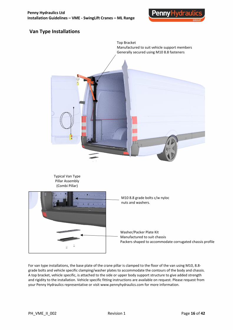
Van Type Installations
For van type installations, the base plate of the crane pillar is clamped to the floor of the van using M10, 8.8-grade bolts and vehicle specific clamping/washer plates to accommodate the contours of the body and chassis. A top bracket, vehicle specific, is attached to the side or upper body support structure to give added strength and rigidity to the installation. Vehicle specific fitting instructions are available on request. Please request from your Penny Hydraulics representative or visit www.pennyhydraulics.com for more information.
Top Bracket Manufactured to suit vehicle support members Generally secured using M10 8.8 fasteners
Typical Van Type Pillar Assembly (Combi Pillar)
Washer/Packer Plate Kit Manufactured to suit chassis Packers shaped to accommodate corrugated chassis profile
M10 8.8 grade bolts c/w nyloc nuts and washers.

Penny Hydraulics Ltd Installation Guidelines – VME - SwingLift Cranes – ML Range
PH_VME_II_002 Revision 1 Page 17 of 42
Pick-Up Type Installations
For pick up type installations, the crane pillar is fitted and bolted through the floor of the vehicle. To achieve the required strength for supporting the assembly, a vehicle specific subframe must be manufactured to be secured to the vehicle chassis or vehicle body. The installer must comply with the chassis manufacturers body builder guidelines. Only use existing fixing points in the chassis if they are available, do not alter or modify the chassis in any way. Additional fixing points, brackets and structure may be bolted to the body sections where required. Vehicle specific fitting instructions available on request. Please request from your Penny Hydraulics representative or visit www.pennyhydraulics.com for more information.
Typical Sub Frame Manufactured to suit and secure to vehicle chassis/body
Subframe installation
M12 8.8 grade bolts c/w nyloc
nuts and washers.

Penny Hydraulics Ltd Installation Guidelines – VME - SwingLift Cranes – ML Range
PH_VME_II_002 Revision 1 Page 18 of 42
Installation – Electrical The Knuckle Joint crane is powered from the vehicle battery. Before carrying out any electrical works it is important to check the compatibility with the vehicle electrical system and always be aware of the possibility of causing damage or injury if the job is not planned and implemented correctly. All electrical connections should be made following manufacturers recommendations.
80/0.40 10mm² single core cable to be used for the power supply. Max cable run length with this spec cable for the positive supply is 11m. Seek advice on the correct cable specification if the cable run is longer than 11m. This is fused at the battery with a 60 amp single blow fuse. A common ground point on the vehicle chassis is normally used for a negative connection. All cable runs should be kept to a minimum and as such, it is not recommended to take the earth all the way back to the battery. Excessive cable runs will result in a voltage drop, increased amp draw and possible overload. A push button pendant control provides the up / down/emergency stop signal to a solenoid located in a junction box on the crane body. It is important that all cables are routed securely and safely from the battery to the crane. Seal all points of entry/exit through the body/chassis and ensure chafing cannot occur at any point. Take care when drilling holes for routing and securing cable and always ensure the area is clear for the drill to break through without causing damage to the structure/components behind the area being drilled. All joints and holes should be sealed and rust proofed to comply with manufacturers guidelines. The crane performance is proportional to the battery performance. Especially for 12V vehicles, we recommend the additional installation of a second battery with the same or greater A/hr rating as the original one, connected in parallel (or replace the existing battery with a heavy “traction” type). The battery is to be kept in perfect working order. During crane operation, check that the voltage to the terminals never drops below 10.5 V (for 12V vehicles), or 19 V (for 24V vehicles), both for reducing the current in the motor which causes overheating. Check the type and efficiency of the vehicle's alternator with the vehicle manufacturer, considering the crane install. In some cases, it may be advisable to replace the original alternator with one of greater output.
Vehicle ground/earthing point as close as possible to the crane
and battery
Pendant control to be disconnected and
Secured safely when not in use
Power cables Positive supply: Red 80/0.40 10mm²
For maximum cable run of 11m Negative Ground: Black 80/0.40 10mm²
Route, secure and protect through chassis/body
Vehicle battery 60A fuse assembly
Connector plug Disconnect and
secure safely when not in use
Solenoid Junction Box

Penny Hydraulics Ltd Installation Guidelines – VME - SwingLift Cranes – ML Range
PH_VME_II_002 Revision 1 Page 19 of 42
Typical Wiring Layout

Penny Hydraulics Ltd Installation Guidelines – VME - SwingLift Cranes – ML Range
PH_VME_II_002 Revision 1 Page 20 of 42
Installation Technical Files
Who the guidance is aimed at
• Manufacturers and installers of loader cranes.
• Persons conducting thorough examinations of loader cranes and their employers.
• Persons and organisations that own and operate loader cranes.
• National enforcing authorities.
• Any other persons who may be deemed a duty holder under the requirements of the Lifting
Operations & Lifting Equipment Regulations (LOLER) 1998, or the Provision and Use of Work
Equipment Regulations (PUWER) 1998.
What the law says
• Loader crane installers should record and maintain the contents of a technical file covering the installation from enquiry to handover. Technical files demonstrate how machinery meets the relevant health and safety requirements. Note: Lorry loader technical files are also commonly referred to as ‘build files’.
• The Supply of Machinery (Safety) Regulations 2008 require the technical file to be retained for at least
10 years from the machinery’s date of manufacture.
• Manufacturers/installers are not obliged to make the contents of technical files available to other
suppliers, or eventual users of the machinery. However, it is a recommendation in BS7121 Part 4 at
11.4 that the owner/duty holder maintains records, such as: "technical information, including
maintenance instructions and performance data provided by the manufacturer".
Note: The contents of the ‘machine history file’ kept by the loader crane owner are listed in BS7121-2-4, 7.5.
Technical file contents guidance A typical lorry loader technical file could contain the following:
• Order Confirmation: Including copies of production specifications and drawings; and a general description of the machinery.
• Technical Calculations and Drawings: These could include installation instructions; payload, axle loading and stability calculations; subframe designs and specifications; and stability monitoring system settings. These calculations and drawings are commonly completed using manufacturer technical calculation software packages.
• Note: Further detail on the required contents of loader crane mounting instructions are listed in BS-EN12999, 7.2.2.
• Note: The installer is responsible for carrying out the loader crane manufacturer’s installation instructions.
• Loader Crane Manufacturer’s EC Declaration(s) of Conformity.

Penny Hydraulics Ltd Installation Guidelines – VME - SwingLift Cranes – ML Range
PH_VME_II_002 Revision 1 Page 21 of 42
Commissioning documents This could include: -
• The commissioning Report of Thorough Examination for the loader crane
• Stability test report
• Calculations of stability at intermediate positions
• Lorry loader inspection sheet
• Function test
• Dynamic test and calibration test records
• Any other technical reports and certificates, such as the end of build compliance check sheets and
non-compliance reports.
For further information on installation testing and test procedures, refer to BS-EN12999, clause 6.2.
Vehicle manufacturer recommendations The process of checking the vehicle manufacturer’s recommendations should be verifiable. This could include taking photographs and retaining any drawings that have been followed as proof that these checks have been made, and the work complies with the recommendations. Typically, this could also include a documented incoming chassis inspection assessment report, Certificate of Completion, weight tests including axle loadings.
Electrical drawings
• Including installation wiring diagrams of electrical systems and control circuits.
• Check sheets & inspection report forms.
• Signed and dated check sheets showing all items checked by the installer, including stage inspections; installation completion inspections; quality control reports.
Photographs
• Photographs could be of assistance during repeat builds and may assist in dispute resolution, if required.
Vehicle collection/handover documents
• Including a checklist of all handover items not covered elsewhere, such as warranty information and service log books.
Axle loading & stability calculations
• It is essential that axle loading and stability calculations are made before any vehicle-mounted lifting equipment is purchased. Reputable commercial vehicle converters, bodybuilders and lifting equipment manufacturers that offer fitting will offer this service. The calculations will determine if a product is suitable, depending on what needs to be lifted and where the item needs to be placed. These checks are essential in order to ensure that plated axle loads are not exceeded and that loads can be distributed evenly in both running order (unladen) and at gross vehicle weight (when the load takes mass off the front axle).
• These calculations also generate a theoretical stability envelope with the crane and its subframe in position and determine possible stabiliser leg requirements. A commercial vehicle may be stable when the boom is fully retracted, but there may be non-linear moments with the mass of the

Penny Hydraulics Ltd Installation Guidelines – VME - SwingLift Cranes – ML Range
PH_VME_II_002 Revision 1 Page 22 of 42
extending booms themselves which will also contribute to the tipping point. This may well require working with an OEM and third-party converter to determine an adequate chassis and subframe.
• From a design and construction perspective, stress calculations which take into account the torsional rigidity and mass of the chassis, using OEM’s data is key, but it shouldn’t end there. From an operational perspective, understanding the exact current and future duties of the vehicle and loader crane is vital. A higher specification crane is likely to require a heavier duty chassis cab.
Whole Vehicle Type Approval Further to confirmation from the Vehicle Certification Agency on 06.10.16, Penny Hydraulics can confirm that:
• Cranes fitted internally into vans are out of the scope of the Enhancement Scheme.
• Cranes fitted to chassis cabs are outside the scope of Whole Vehicle Type Approval if the Mass in
Running Order of the vehicle is not increased by more than 3%. Mass in Running Order is the weight
of the van or chassis cab as it left the factory including a full fuel tank and a nominal driver weight of
75kg. If the 3% is exceeded, the crane must be fitted post registration and is then classed as payload.
• On fitting the crane, the installer must carry out overall/axle mass-checks, stability calculations and
supply a test certificate.
In the above cases, the vehicle does not require a further stage of Type Approval or Individual Vehicle
Approval.

Penny Hydraulics Ltd Installation Guidelines – VME - SwingLift Cranes – ML Range
PH_VME_II_002 Revision 1 Page 23 of 42
Thorough Examination The Lifting Operations and Lifting Equipment Regulations (LOLER) replaced the legal requirement for the four-yearly Overload Test with the annual Thorough Examination and Inspection, and made it the responsibility of the Competent Person to determine if and when an Overload Test should be carried out, on the grounds that "the design of certain lifting equipment is such that damage may be caused by conventional Overload Tests". Loader cranes do not fall into this category, as witnessed by the fact that BS7121 Part 2 has an entire section devoted to the testing of loader cranes. Load Testing is a requirement of ALLMI and BS7121 Parts 2 and 4. Inspection of the lorry loader by a competent person to determine if it is safe for continued use until the next
thorough examination is due. Thorough Examinations should be conducted at least every 12 months. A
thorough examination will also be required:
• If the lorry loader is involved in an accident or dangerous occurrence.
• After a significant change in conditions of use.
• After long periods out of use.
• At shorter intervals as determined by the Competent Person.
Please note that in addition to the above, lifting equipment for lifting persons or an accessory for lifting,
must be thoroughly examined at least every six months.
BS7121 Part 2
Occasion Minimum test and thorough examination
Before being first taken into service Full test including 25% overload
Annually after being first put into service Proof load test of rated capacity +10% at full radius and through the full slewing arc, and a Thorough Examination
4 years after first being put into service Full test including 25% overload
8 years after first being put into service Non-destructive test of structure
After each structural repair or component change Full test including 25% overload
When chassis is changed Full test including 25% overload
Is removed and refitted Full test including 25% overload

Penny Hydraulics Ltd Installation Guidelines – VME - SwingLift Cranes – ML Range
PH_VME_II_002 Revision 1 Page 24 of 42
Visual Inspection The lorry loader can be operated (with caution) for this inspection.
• Check visually for signs of external damage.
• Check all guards are securely in place.
• Check for loose or missing nuts, bolts and fasteners.
• Check the hoist rope for kinks, broken strands and corrosion.
• Check the lifting hook and connection to the rope.
• Check for damage to electrical cables and connectors
Function Check The operational functions of the crane shall be tested with no load to demonstrate the following:
• The satisfactory operation of each control device. Check for smoothness of operation and ensure that
all controls return to neutral when released. Check that the motion is in the direction as indicated by
the decal.
• The satisfactory operation of each crane motion.
• The crane functions should be operated throughout the full range of permitted movements up to the
maximum speeds.
Crane support legs
• Check that the stabiliser beams slide in and out correctly, where applicable. Also, check for wear and
security.
• Check the operation and locking of swing up stabilisers, if fitted.
• Ensure that stabiliser legs make firm contact with the ground and do not creep during operation.
• Check the stabiliser foot pads fitted to the stabilisers.
• Check the condition of any supplementary load spreader mats.
Hoist (if fitted) Check:
• Manufacturers Guidelines - Three turns remain on the hoist drum (red rope).
• Overload limit is set correctly.
Running In
• All functions are to be operated without load, throughout their permitted range.
• If a hoist is fitted, the hoist drum should be rotated four times in each direction.
• Slew the loader crane fully, clockwise and anticlockwise.

Penny Hydraulics Ltd Installation Guidelines – VME - SwingLift Cranes – ML Range
PH_VME_II_002 Revision 1 Page 25 of 42
Calibration Check
Test Weights
• The following test weights should be used. o Weights of proven accuracy to within +/-1.0%.
o Weights proven on a weighbridge. The weighbridge must have been calibrated to within +/-
1.0% within the last 12 months.
o For weights suspended from a calibrated weighing device, the weighing device must have
been calibrated to within +/-1.0% within the last 12 months.
• Check that the Rated Capacity Limiter operates to prevent dangerous movements and allows return
movements to a safe condition.
• Remember that the test load shall be the combination of the test weight and any slings or chains.
Dynamic Test The object of this test is to subject the structural members to dynamic conditions and fluctuating loads, in order to check functionality through its full range of travel.
• Dynamic tests should be performed separately for each loader crane motion.
• Testing shall be carried out at speeds to those appropriate for normal crane operation and shall
include repeated starting and stopping of each motion throughout the range of the motion. However,
aggressive shock loading should be avoided.
• The test load shall be 110% of the Rated Capacity for the maximum extension.
• All crane positions attainable in service should be reached during the course of the tests.
• The test shall be considered successful if all components have been found to perform their functions
correctly in accordance with the design specification and if an examination after the test reveals no
damage to the mechanisms or structural components.

Penny Hydraulics Ltd Installation Guidelines – VME - SwingLift Cranes – ML Range
PH_VME_II_002 Revision 1 Page 26 of 42
Overload Test
Introduction The purpose of the overload test is to confirm the structural integrity of the lorry loader. This includes
anchorages to the vehicle, vehicle structural parts and stabiliser legs.
• Before the overload test takes place, the thorough examination should have determined whether the
loader crane is free from any defect that would prevent it from safely handling the test load and that
it is in the correct configuration and condition according to the instructions. All lifting accessories
should also be thoroughly examined before the Load Test to ensure they are safe for use.
• Before the overload and stability tests, check the loader crane’s reaction with Rated Capacity for
maximum extension. i.e. does the vehicle appear stable?
• The loader crane should be tested in all configurations and rated capacities for which it is designed to
be used.
• All attachments with the exception of the hook should be removed before testing.
• Ensure that the stabiliser legs are fully extended and that the vehicle tyres are inflated to the
manufacturer’s recommended pressure. If the loader crane is mounted on a vehicle with active air
suspension, the air must be dumped and locked off in the fully deflated position before deploying the
stabilisers. Ensure that the stabiliser legs are in firm contact with the ground, to the extent that they
provide adequate support for the loader crane, but not as to take the load from the wheel and reduce
the efficiency of the parking brake.
• Remember that the weight of all additional lifting equipment fitted to the loader crane should be
regarded as part of the test load.
• The test should be carried out using an unloaded vehicle, without the operator in the cab.
• For the overload test to be performed, the overload protection system should be overridden or
disconnected (see below).
• All safety devices should be reconnected and where appropriate, reset, retested and resealed before
the lorry loader is released from testing.
How to override the overload protection Overload protection is pre-configured in the factory and will prevent you from carrying out an overload test
without following the override procedure below.
• Locate the microswitch installed at the rear of the hoist baseplate.
• Use tapered steel (feeler gauges/flat bladed screwdriver blade) to depress the microswitch actuator
when overload protection initiates. This will override the overload protection and allow you to
perform the overload test.
• Ensure the tapered steel shim is removed on completion of the overload test.
Performing the overload test
• The test load shall be 125% of the Rated Capacity of the lorry loader.
• The Competent Person should clearly indicate when the test starts and when it has been completed.
During the test, any operator and/or slinger should accept instructions from only the Competent
Person (with the exception of the emergency stop signal).
• If the operator feels that the instructions create an unsafe situation then they should stop and seek
further advice from their employer.
• The test shall be considered successful if no connection has been loosened or damaged and if there
are no cracks, permanent deformation, paint flaking or damage which affect the function and safety
of the loader crane and its installation.
• The test shall be carried out with the test load at the following radii:

Penny Hydraulics Ltd Installation Guidelines – VME - SwingLift Cranes – ML Range
PH_VME_II_002 Revision 1 Page 27 of 42
o Maximum radius attainable.
o At the shortest practical radius shown on the Rated Capacity chart.
Note – The test for maximum radius is not required if a Stability Test is made for the same radius.
• At each radius the load should be positioned as close to the ground as possible, allowing for vehicle
stability and boom deflection. Slew slowly through the full in-service slewing arc of the loader crane.
• Avoid shock loading, which can be caused by rapid acceleration of loader crane motions, sudden
braking or erratic movements.
1st & 2nd Visual Inspection
• Following the dynamic and overload tests, the loader crane should be inspected for signs of structural damage that will affect its safety. Look for:
o Cracking.
o Permanent deformation.
o Paint flaking.
o Loosening of, or damage to, structural connections.
o Twists or deflections in the chassis.
• If any of the above are found then the test should be considered unsuccessful. After repairs have
been carried out the full test should be re-applied.
• Check for any signs that electrical cables have been snagging.
Final Checklist
• Check that the manufacturers plate has been stamped and correctly fitted to the crane. • Check that the installers plate has been stamped and correctly fitted to the crane. • Check that the crane Operating and Maintenance manual is present.
• Check that the LOLER commissioning test certificate is present.
Preparing & Issuing a Report of Thorough Examination &
Test
• On completion of a successful test, a test certificate should be completed. The certificate should be signed by the person completing the test.
• It should be ensured by the Competent Person that the rated capacities stated in the Report of
Thorough Examination are identical to those given on the load plates of the crane.
• Explain to the employer/owner, the legal requirement for the keeping of the report (refer to LOLER).

Penny Hydraulics Ltd Installation Guidelines – VME - SwingLift Cranes – ML Range
PH_VME_II_002 Revision 1 Page 28 of 42
Appendix
Spare Parts List
ML250– Exploded View

Penny Hydraulics Ltd Installation Guidelines – VME - SwingLift Cranes – ML Range
PH_VME_II_002 Revision 1 Page 29 of 42
ML250 – Parts List
ITEM PART NUMBER DESCRIPTION QTY 1 a Subject to Specification Van Pillar - Assembly 1
b 541-000124 Combi Pillar - Assembly 1
c 011-000441 Corner Bracket - Assembly 1
2 a 190-000006 Support Leg (2 Tier) - Assembly 1
b 190-000015 Support Leg (3 Tier) - Assembly 1
3 503-000078 Leg Extension - Assembly 1
4 158-000029 Cranked Hinge - Assembly 1
5 Subject to Specification Van Top Mounting Bracket - Assembly 1
6 052-000027 Crane Body - Assembly 1
7 a 056-000135 Long Boom (LB) Left Hand - Assembly 1
b 056-000142 Long Boom (LB) Right Hand - Assembly 1
c 056-000139 Short Boom (SB) Left Hand - Assembly 1
d 056-000143 Short Boom (SB) Right Hand - Assembly 1
8 060-000012 Stay Bar - Assembly 1
9 a 195-000040 Solenoid Box & Wiring Harness - 12V 1
b 195-000041 Solenoid Box & Wiring Harness - 24V 1
10 547-000033 Remote Connector & Tail 1
11 108-000001 Anderson Power Connector - 50A 1
12 539-000043 Lynch Pin 1
13 713-200005 Disc Spring - Assembly 1
14 692-000008 Microswitch - Assembly 1
15 a 123-000035 Winch Cover - L/H 1
b 123-000036 Winch Cover - R/H 1
16 a 077-000024 Winch Assembly - 12V - Left Hand (LH) 1
b 077-000023 Winch Assembly - 12V - Right Hand (RH) 1
c 077-000026 Winch Assembly - 24V - Left Hand (LH) 1
d 077-000025 Winch Assembly - 24V - Right Hand (RH) 1
17 042-000001 Terminal Rubber Boot 2
18 a 614-000005 Winch Motor - 12V 1
b 614-000007 Winch Motor - 24V 1
19 200-000009 Shoulder Bolt - Assembly 1
20 539-000133 Boom Hinge Pin - Assembly 1
21 539-000134 Stay Bar Pin - Assembly 1
22 555-000016 Pulley Wheel - Assembly 1
23 a 022-000002 Bob Weight - Assembly 1
b 022-000004 Half Bob Weight - Assembly 1
24 a 079-000008 Rope 15' (4.5m) & Hook - Assembly 1
b 079-000009 Rope 20' (6.0m) & Hook - Assembly 1
c 079-000010 Rope 30' (9.1m) & Hook - Assembly 1
25 560-000016 Remote Control (3 Button Handset) 1
26 Subject to Specification Support Leg Stowage Bracket - Assembly 1
27 079-000050 Rope Hook (Bulkhead Mounted) - Assembly 1
28 035-000049 Flanged Bush 2
ITEM PART NUMBER DESCRIPTION QTY
1 a Subject to Specification Van Pillar - Assembly 1
b 541-000124 Combi Pillar - Assembly 1
c 011-000441 Corner Bracket - Assembly 1

Penny Hydraulics Ltd Installation Guidelines – VME - SwingLift Cranes – ML Range
PH_VME_II_002 Revision 1 Page 30 of 42
2 a 190-000006 Support Leg (2 Tier) - Assembly 1
b 190-000015 Support Leg (3 Tier) - Assembly 1
3 503-000078 Leg Extension - Assembly 1
4 158-000029 Cranked Hinge - Assembly 1
5 Subject to Specification Van Top Mounting Bracket - Assembly 1
6 056-000314 Crane Body 1
7 056-000313 2nd Boom 1
8 064-000001 Antiluce Fastener - Assembly 1
9 539-000043 Lynch Pin 1
10 173-000006 Rubber Holder (Male & Female) - Assembly 1
11 a 195-000040 Solenoid Box & Wiring Harness - 12V 1
b 195-000041 Solenoid Box & Wiring Harness - 24V 1
12 035-000056 Joint Bearing - Assembly 1
13 713-200005 Disc Spring - Assembly 1
14 200-000009 Shoulder Bolt - Assembly 1
15 a 077-000024 Winch Assembly - 12V - Left Hand (LH) 1
b 077-000023 Winch Assembly - 12V - Right Hand (RH) 1
c 077-000026 Winch Assembly - 24V - Left Hand (LH) 1
d 077-000025 Winch Assembly - 24V - Right Hand (RH) 1
16 692-000008 Microswitch - Assembly 1
17 a 123-000035 Winch Cover - L/H 1
b 123-000036 Winch Cover - R/H 1
18 042-000001 Terminal Rubber Boot 2
19 555-000017 Pulley Wheel - Assembly 1
20 a 022-000002 Bob Weight - Assembly 1
b 022-000004 Half Bob Weight - Assembly 1
21 a 079-000008 Rope 15' (4.5m) & Hook - Assembly 1
b 079-000009 Rope 20' (6.0m) & Hook - Assembly 1
c 079-000010 Rope 30' (9.1m) & Hook - Assembly 1
22 560-000016 Remote Control (3 Button Handset) 1
23 Subject to Specification Support Leg Stowage Bracket - Assembly 1
24 035-000049 Flanged Bush 2

Penny Hydraulics Ltd Installation Guidelines – VME - SwingLift Cranes – ML Range
PH_VME_II_002 Revision 1 Page 31 of 42
ML500 – Exploded View

Penny Hydraulics Ltd Installation Guidelines – VME - SwingLift Cranes – ML Range
PH_VME_II_002 Revision 1 Page 32 of 42
ML500 – Parts List
ITEM PART NUMBER DESCRIPTION QTY 1 a Subject to Specification Van Pillar - Assembly 1
b 541-000200 Combi Pillar - Assembly 1
c 011-000440 Corner Bracket - Assembly 1
2 a 190-000006 Support Leg (2 Tier) - Assembly 1
b 190-000015 Support Leg (3 Tier) - Assembly 1
3 503-000078 Leg Extension - Assembly 1
4 Subject to Specification Van Top Mounting Bracket - Assembly 1
5 052-000010 Crane Body - Assembly 1
6 a 056-000145 Long Boom (LB) Left Hand - Assembly 1
b 056-000140 Long Boom (LB) Right Hand - Assembly 1
c 056-000334 Short Boom (SB) Left Hand - Assembly 1
d 056-000206 Short Boom (SB) Right Hand - Assembly 1
7 a 056-000141 Long Boom (LB) Extension - Assembly 1
b 056-000203 Short Boom (SB) Extension - Assembly 1
8 060-000015 Stay Bar - Assembly 1
9 a 195-000040 Solenoid Box & Wiring Harness - 12V 1
b 195-000041 Solenoid Box & Wiring Harness - 24V 1
10 547-000033 Remote Connector & Tail 1
11 108-000001 Anderson Power Connector - 50A 1
12 539-000043 Lynch Pin 1
13 713-200004 Disc Spring - Assembly 1
14 692-000008 Microswitch - Assembly 1
15 a 123-000035 Winch Cover - L/H 1
b 123-000036 Winch Cover - R/H 1
16 a 077-000024 Winch Assembly - 12V - Left Hand (LH) 1
b 077-000023 Winch Assembly - 12V - Right Hand (RH) 1
c 077-000026 Winch Assembly - 24V - Left Hand (LH) 1
d 077-000025 Winch Assembly - 24V - Right Hand (RH) 1
17 042-000001 Terminal Rubber Boot 2
18 a 614-000005 Winch Motor - 12V 1
b 614-000007 Winch Motor - 24V 1
19 200-000009 Shoulder Bolt - Assembly 1
20 539-000135 Boom Hinge Pin - Assembly 1
21 539-000368 Stay Bar Pin - Assembly 1
22 539-000130 Extension Locking Pin - Assembly 1
23 555-000018 Pulley Wheel - Assembly 1
24 a 022-000002 Bob Weight - Assembly 1
b 022-000004 Half Bob Weight - Assembly 1
25 a 079-000008 Rope 15' (4.5m) & Hook - Assembly 1
b 079-000009 Rope 20' (6.0m) & Hook - Assembly 1
c 079-000010 Rope 30' (9.1m) & Hook - Assembly 1
26 560-000016 Remote Control (3 Button Handset) 1
27 Subject to Specification Support Leg Stowage Bracket - Assembly 1
28 079-000050 Rope Hook (Bulkhead Mounted) - Assembly 1
29 039-000002 Flanged Bush 2

Penny Hydraulics Ltd Installation Guidelines – VME - SwingLift Cranes – ML Range
PH_VME_II_002 Revision 1 Page 33 of 42
Lorry Loader Servicing
Thank you for purchasing our product. Penny Hydraulics Limited manufactures a range of Swinglift Cranes,
Taillift, Steplift, Loadlift and Tyre Press products, which are supported by a fleet of dedicated service vans fully
stocked with original equipment spares and manned by trained engineers.
Current legislation requires that each item of lifting equipment must be thoroughly examined at least once in
every period of twelve months by a competent person. Additionally, the lifting equipment must be inspected
at suitable intervals between thorough examinations. Our service contract will ensure continued safe, reliable
use of the equipment and full compliance with current legislation.
The operator is required to carry out regular inspections and report any faults found.
The standard contract provides for an annual service and an interim six-monthly inspection or for total peace
of mind we offer a Fully Comprehensive option. In all cases, a test certificate will be issued with a copy being
left on site and a further copy sent together with our invoice. We will also keep a copy for our records that can
be forwarded to enforcing authorities on your behalf as necessary.
Our database of all equipment ensures that statutory inspections are kept up to date and can help customers
with many items of equipment to predict forthcoming servicing budgets.
A Help Line telephone number is provided with each service contract for the operators to seek assistance
directly from our Service Department. There is no call out or labour charge for help required in-between
scheduled visits and any parts used will be charged on the next invoice.
Should this be of interest then in the first instance please contact the service department on 01246 810403.

Penny Hydraulics Ltd Installation Guidelines – VME - SwingLift Cranes – ML Range
PH_VME_II_002 Revision 1 Page 34 of 42
Equipment Register for Penny Hydraulics Limited Service Contract Company Name: _____________________________________________________
If necessary please duplicate this form Signature: ________________________________ Print Name: ________________________________ Position: ________________________________ Date: ________________________________
Equipment Type / Model Number
Date Of Manufacture / Serial Number
Date of Last Service
Vehicle Type
Vehicle Registration
Name & Contact Telephone / Fax No.
Equipment Location (Where it can be serviced)
Name:
Tel:
S/N: Fax:
Name:
Tel:
S/N: Fax
Name:
Tel:
S/N: Fax:
Name:
Tel:
S/N: Fax:
Name:
Tel:
S/N: Fax:
Name:
Tel:
S/N: Fax:
Name:
Tel:
S/N: Fax:

Penny Hydraulics Ltd Installation Guidelines – VME - SwingLift Cranes – ML Range
PH_VME_II_002 Revision 1 Page 35 of 42
Credit Account Application
Company Name: A/C No:
Address:
Telephone No: Fax No:
E-Mail:
Credit Account: Cash Account:
Company Registration No: Credit Limit Required:
Accounts Contact:
Bankers Name:
Address:
Trade References:
1) 2)
Tel No: Tel No:
Fax: Fax:
Penny Hydraulics Ltd General Conditions of Sale will apply, a copy of which is attached.
Please note that our trading terms are strictly thirty days from the date of invoice and that by signing
this document the customer agrees to adhere to this and fully accepts our General Conditions of Sale.
We understand and will retain the statutory right to claim interest and compensation for debt recovery
costs under the late payment legislation if we are not paid according to agreed terms.
Goods remain the property of Penny Hydraulics until paid in full.
Signed: Print Name:
Position in Company (to be signed by a Director): Date:

Penny Hydraulics Ltd Installation Guidelines – VME - SwingLift Cranes – ML Range
PH_VME_II_002 Revision 1 Page 36 of 42
Penny Hydraulics Ltd Standard Terms and Conditions (for the Supply of
Goods and Services to non-consumers)
1 Interpretation 1.1 Definitions. In these Conditions, the following definitions apply: Business Day: a day (other than a Saturday, Sunday or public holiday) when banks in London are open for business. Conditions: the terms and conditions set out in this document as amended from time to time. Confidential Information: all trade secrets, know-how, data, specifications, drawings, documents, techniques and technical data, processes, materials, apparatus and intellectual property of any kind whatsoever. Contract: the contract between the Supplier and the Customer for the sale and purchase of the Goods and/or Services in accordance with these Conditions. Customer: the person or entity who purchases the Goods and/or Services from the Supplier. Force Majeure Event: has the meaning given in clause 10. Goods: the goods (or any part of them) as set out in the Order/Order Acknowledgment. Order: the Customer’s order for the Goods and/or Services, as set out in the Customer’s purchase order form OR in the Customer’s acceptance of the Supplier’s quotation as the case may be. Order Acknowledgment: the Supplier's written acknowledgement of the Customer's purchase order. Services: the services to be carried out by the Suppliers as per the Order/Order Acknowledgment. Specification: any specification for the Goods and/or Services, including any related plans and drawings, that are agreed in writing by the Customer and the Supplier. Supplier: Penny Hydraulics Ltd (registered in England and Wales with Company Number 01380206). 1.2 Construction. In these Conditions, the following rules apply:
(a) A person includes a natural person, corporate or unincorporated body (whether or not having separate legal personality).
(b) A reference to a party includes its personal representatives, successors or permitted assigns.
(c) A reference to a statute or statutory provision is a reference to such statute or provision as amended or re-enacted. A reference to a statute or statutory provision includes any subordinate legislation made under that statute or statutory provision, as amended or re-enacted.
(d) Any phrase introduced by the terms including, include, in particular or any similar expression shall be construed as illustrative
and shall not limit the sense of the words preceding those terms.
(e) A reference to writing or written includes faxes and e-mails.
2 Basis of Contract 2.1 These Conditions apply to the Contract to the exclusion of any other terms that the Customer seeks to impose or incorporate, or which are implied by trade, custom, practice or course of dealing. 2.2 The Order constitutes an offer by the Customer to purchase the Goods and/or Services in accordance with these Conditions. The Customer is responsible for ensuring that the terms of the Order and any applicable Specification submitted by the Customer are complete and accurate. 2.3 The Order shall only be deemed to be accepted when the Supplier issues a written acceptance of the Order, at which point the Contract shall come into existence. 2.4 The Contract constitutes the entire agreement between the parties. The Customer acknowledges that it has not relied on any statement, promise or representation made or given by or on behalf of the Supplier which is not set out in the Contract.

Penny Hydraulics Ltd Installation Guidelines – VME - SwingLift Cranes – ML Range
PH_VME_II_002 Revision 1 Page 37 of 42
2.5 Any samples, drawings, descriptive matter, or advertising produced by the Supplier and any descriptions or illustrations contained in the Supplier’s catalogues or brochures are produced for the sole purpose of giving an approximate idea of the Goods and/or Services described in them. They shall not form part of the Contract or have any contractual force unless expressly stated to the contrary. 2.6 A quotation for the Goods and/or Services given by the Supplier shall not constitute an offer.
3 Goods 3.1 To the extent that the Goods are to be manufactured and/or installed in accordance with the Specification supplied by the Customer, the Customer shall indemnify the Supplier against all liabilities, costs, expenses, damages and losses (including any direct, indirect or consequential losses, loss of profit, loss of reputation and all interest, penalties and legal and other professional costs and expenses) suffered or incurred by the Supplier in connection with any claim made against the Supplier for actual or alleged infringement of a third party’s intellectual property rights arising out of or in connection with the Supplier’s use of the Specification. This clause 3.1 shall survive termination of the Contract. 3.2 The Supplier reserves the right to amend the Specification if required by any applicable statutory or regulatory requirements.
4 Delivery 4.1 The Supplier shall deliver the Goods to the location set out in the Order or such other location as the parties may agree (Delivery Location) at any time after the Supplier notifies the Customer that the Goods are ready to be delivered. 4.2 Delivery of the Goods shall be completed on the Goods’ arrival at the Delivery Location. 4.3 Any dates quoted for delivery of the Goods/the carrying out of the Services are approximate only, and the time is not of the essence. Whilst every effort will be made by the Supplier to deliver the Goods and/or carry out the Services on or before the date stated, no binding guarantee is given or implied and no claim will be accepted by the Supplier arising from or in connection with late delivery. Further, the Supplier shall not be liable for any loss or damage of any kind and howsoever arising by reason of any failure to deliver the Goods/carry out the Services on such stated dates. 4.4 The Supplier may deliver the Goods in more than one consignment even if not envisaged by the Order and/or Order Acknowledgment. 4.5 If the Supplier fails to deliver the Goods and/or perform the Services (in whole or part), its liability shall be limited to the costs and expenses incurred by the Customer in obtaining replacement Goods and/or Services of similar description and quality in the cheapest market available, less the price of the Goods and/or Services. The Supplier shall have no liability for any failure to deliver the Goods and/or Services to the extent that such failure is caused by a Force Majeure Event or the Customer’s failure to provide the Supplier with adequate delivery instructions or any other instructions that are relevant to the supply of the Goods and/or Services. 4.6 If the Customer fails to take or accept delivery of the Goods or allow the Services to be performed within three Business Days of the Supplier notifying the Customer that the Goods/Services are ready to be delivered/performed, then, except where such failure or delay is caused by a Force Majeure Event or the Supplier’s failure to comply with its obligations under the Contract:
(a) delivery of the Goods/performance of the Services shall be deemed to have been completed at 9.00 am on the third Business Day after the day on which the Supplier notified the Customer that the Goods were ready for delivery/services ready to be performed and the Supplier will be entitled to invoice accordingly;
(b) the Supplier shall store the Goods until any actual delivery takes place, and charge the Customer for all related losses, costs and
expenses (including insurance); and
(c) The Supplier will be entitled to charge the Customer for all related losses, costs and expenses caused as a result of having to re-schedule the performance of the Services.
4.7 If 10 Business Days after the day on which the Supplier notified the Customer that the Goods/Services were ready for delivery/performance the Customer has not taken or accepted delivery of the Goods/Services, the Supplier may resell or otherwise dispose of part or all of the Goods and, after deducting reasonable storage and selling costs, account to the Customer for any excess over the price of the Goods or charge the Customer for any shortfall below the price of the Goods. The Supplier would then be released from any obligation to perform the Services.
5 Quality 5.1 The Supplier warrants that on delivery, and for a period of 12 months from the date of delivery/performance (Warranty Period), the Goods and/or Services shall:
(a) conform (in essence) with their description and the Specification;
(b) be free from material defects in design, material and workmanship; and
Penny Hydraulics Ltd Installation Guidelines – VME - SwingLift Cranes – ML Range
PH_VME_II_002 Revision 1 Page 38 of 42
(c) be of satisfactory quality (within the meaning of the Sale of Goods Act 1979 and/or the supply of Goods and Services Act 1982);
and
(d) be fit for any purpose held out by the Supplier. 5.2 Subject to clause 5.3, if:
(a) the Customer gives notice in writing to the Supplier during the Warranty Period and within a reasonable time of discovery (in any event no later than 14 days from discovery) that some or all of the Goods and/or Services do not comply with the warranty set out in clause 5.1;
(b) the Supplier is given a reasonable opportunity of examining such Goods and/or Services; and
(c) the Customer (if asked to do so by the Supplier) returns such Goods to the Supplier’s place of business at the Supplier’s cost,
the Supplier shall, at its option, repair or replace the defective Goods and/or remedy any defective Services , or refund the price of the defective Goods and/or Services in full;
(d) no defect in the Goods and/or Services is found for which the Supplier is liable, the Supplier shall be entitled to compensation
(on an indemnity basis) for the costs he has incurred as a result of the notice. 5.3 The Supplier shall not be liable for any failure to comply with the warranty set out in clause 5.1 in any of the following events:
(a) the Customer makes any further use of such Goods after giving notice in accordance with clause 5.2;
(b) the defect arises because the Customer failed to follow the Supplier’s oral or written instructions as to the storage, commissioning, installation, use and maintenance of the Goods or (if there are none) good trade practice regarding the same;
(c) the defect arises as a result of the Supplier following any drawing, design or Specification supplied by the Customer;
(d) the Customer alters or repairs such Goods without the written consent of the Supplier;
(e) the defect arises as a result of fair wear and tear, wilful damage, negligence, or abnormal storage or working conditions; or
(f) the Goods and/or Services differ from their description or the Specification as a result of changes made to ensure they comply
with applicable statutory or regulatory requirements. 5.4 Except as provided in this clause 5, the Supplier shall have no liability to the Customer in respect of any failure to comply with the warranty set out in clause 5.1. 5.5 The terms implied by sections 13 to 15 of the Sale of Goods Act 1979 and Section 4 of the Supply of Goods and Services Act 1982 are, to the fullest extent permitted by law, excluded from the Contract. 5.6 These Conditions shall apply to any repaired or replacement Goods or remedied Services supplied by the Supplier.
6 Title and Risk 6.1 The risk in the Goods shall pass to the Customer on completion of delivery. The delivery of Goods by the Supplier to a carrier consigned to the Customer shall constitute the complete transfer of responsibility to the Customer with said carrier thereafter acting on the Customer's behalf. Notwithstanding and without prejudice to the above provision, no claim for damages in transit, shortage of delivery or loss of Goods in transit can be made by the Customer against the Supplier unless:
(i) the issue has without any doubt been caused before the Goods were supplied by the Supplier to the carrier consigned to the Customer;
(ii) in the case of damage in transit or shortage of delivery, a separate notice in writing is given to the carrier concerned and
to the Supplier within 3 days of receipt of Goods followed by a complete claim in writing within 5 days of receipt of Goods.
6.2 As soon as the Goods or any part thereof have been delivered the Goods or that part shall be at the risk of the Customer who shall insure the Goods for the period from the date of delivery until the passing of the property in the Goods to the Customer against any loss of or damage thereto or any part thereof except in those instances where the selling price of the Goods includes installation when the Goods will remain at the Supplier’s risk and insured by the Supplier until they have been installed or up to 30 days from the date of delivery whichever shall be the sooner. 6.3 Title to the Goods shall not pass to the Customer until the Supplier has received payment in full (in cash or cleared funds) for;
(a) The Goods; and
(b) any other goods or Services that the Supplier has supplied to the Customer in respect of which payment has become due.

Penny Hydraulics Ltd Installation Guidelines – VME - SwingLift Cranes – ML Range
PH_VME_II_002 Revision 1 Page 39 of 42
6.4 Until title to the Goods has passed to the Customer, the Customer shall:
(a) hold the Goods on a fiduciary basis as the Supplier’s bailee;
(b) store the Goods separately from all other goods held by the Customer so that they remain readily identifiable as the Supplier’s property;
(c) not remove, deface or obscure any identifying mark or packaging on or relating to the Goods;
(d) maintain the Goods in satisfactory condition and keep them insured against all risks for their full price from the date of
delivery;
(e) notify the Supplier immediately if it becomes subject to any of the events listed in clause 8.2; and
(f) give the Supplier such information relating to the Goods as the Supplier may require from time to time,
(g) shall keep and retain the delivered Goods free from any charge lien or other encumbrance thereon. 6,5 If before title to the Goods passes to the Customer the Customer becomes subject to any of the events listed in clause 8.2, or the Supplier reasonably believes that any such event is about to happen and notifies the Customer accordingly, then without limiting any other right or remedy the Supplier may have, the Supplier may at any time require the Customer to deliver up the Goods and, if the Customer fails to do so promptly, enter any premises of the Customer (the Customer hereby irrevocably grants to the Supplier a licence for that purpose) or of any third party where the Goods are stored in order to recover them. 6.6 The Customer irrevocably accepts that if Goods are capable of being removed by unbolting (or howsoever) so as not to structurally damage the fabric of the building in which they reinstalled/stored they will be deemed to be easily removable, in their original state and not incorporated into the fabric of such said building. 6.7 The provisions of Title & Risk shall survive the termination of the Contract for whatever reason and in particular, but without limitation, termination of the Contract by the Supplier by the acceptance of any repudiation of the Contract by the Customer. 6.8 The Supplier shall be entitled to exercise a general lien or right of retention on all Goods or any parts thereof in the Supplier's possession which are the Customer's property (or which are supplied to the Supplier by the Customer) for any sums whatsoever due to the Supplier and pursuant to such lien or right the Supplier shall be entitled, without notice to the Customer, to sell all or any part of such Goods/property privately or by auction or otherwise and to keep the proceeds of sale in diminution of such sums and of all costs and expenses incurred by the Supplier in effecting the said sales. Any balance remaining thereafter shall be remitted to the Customer by the Supplier. Upon such sale title in the said Goods/property shall pass to the buyer thereof.
7 Price and Payment 7.1 The price of the Goods and/or Services shall be the price set out in the Quotation, Order or Order Acknowledgment (whichever is the latter). 7.2 The Supplier may at any time before delivery/performance, increase the price of the Goods and/or Services to reflect any increase in the cost of the Goods/Services that is due to:
(a) any factor beyond the Supplier’s control (including foreign exchange fluctuations, increases in taxes and duties, increases in line with the consumer price index (CPI) and increases in labour, materials and other manufacturing costs);
(b) any request by the Customer to change the delivery/performance date(s), quantities or types of Goods/Services ordered, or the
Specification; or
(c) any delay caused by any instructions of the Customer or failure of the Customer to give the Supplier adequate or accurate information or instructions.
7.3 The price of the Goods is exclusive of the costs and charges of packaging, insurance and transport of the Goods (unless stated otherwise), which shall be invoiced to the Customer. 7.4 The price of the Goods/Services is exclusive of amounts in respect of value added tax (unless stated otherwise). The Customer shall, on receipt of a valid VAT invoice from the Supplier, pay to the Supplier such additional amounts in respect of VAT as are chargeable on the supply of Goods/Services. 7.5 The Supplier may invoice the Customer for the Goods and Services on or at any time after the completion of delivery/performance. 7.6 The Customer shall pay the invoice in full and in cleared funds on or before the dates(s) stipulated in the Quotation/Order Acknowledgment or other such document and in the event of such not being stipulated therein within 30 days of the date of the invoice. Time of payment is of the essence.

Penny Hydraulics Ltd Installation Guidelines – VME - SwingLift Cranes – ML Range
PH_VME_II_002 Revision 1 Page 40 of 42
7.7 Should the Customer fail to pay the said price or any part thereof within the said period of 30 days or on the date specified in writing the Customer shall pay interest on all amounts outstanding in respect thereof at the rate of 1.5% per month such interest to be compounded and added to the amount outstanding monthly until payment such interest to be chargeable from the date due for payment until payment of all amounts outstanding in respect of the price and such interest. If any payment is in arrears for or on account of or in respect of any Goods and/or Services delivered under this or any other contract between the Supplier and the Customer the Supplier shall have the absolute right without giving any notice to the Customer to suspend further deliveries and services under this or any other such contract and if any such payment or any part thereof shall remain in arrears for seven days after written demand by the Supplier to the Customer the Supplier shall have the right to cancel this and any other such contract without prejudice to all its rights and remedies to recover any monies due and owing from the Customer. 7.8 The Customer will indemnify the Supplier in respect of all/any costs that the Supplier incurs in recovering any debts against the Customer on a full indemnity basis. Further, the Customer will indemnity the Supplier and hold it harmless against all/any claims made by third parties with regard to the Goods and Services supplied. 7.9 The Customer shall pay all amounts due under the Contract in full without any deduction or withholding except as required by law and the Customer shall not be entitled to assert any credit, set-off or counterclaim against the Supplier in order to justify withholding payment of any such amount in whole or in part. The Supplier may at any time, without limiting any other rights or remedies it may have, set off any amount owing to it by the Customer against any amount payable by the Supplier to the Customer. 7.10 Any deposit(s) paid by the Customer to the Supplier will be non-refundable unless expressly stated to the contrary.
8 Customer’s Insolvency or Incapacity 8.1 If the Customer becomes subject to any of the events listed in clause 8.2, or the Supplier reasonably believes that the Customer is about to become subject to any of them and notifies the Customer accordingly, then, without limiting any other right or remedy available to the Supplier, the Supplier may cancel or suspend all further deliveries under the Contract or under any other contract between the Customer and the Supplier without incurring any liability to the Customer, and all outstanding sums in respect of Goods and/or Services delivered to the Customer shall become immediately due. 8.2 For the purposes of clause 8.1, the relevant events are:
(a) the Customer suspends, or threatens to suspend, payment of its debts, or is unable to pay its debts as they fall due or admits inability to pay its debts, or (being a company) is deemed unable to pay its debts within the meaning of section 123 of the Insolvency Act 1986, or (being an individual) is deemed either unable to pay its debts or as having no reasonable prospect of so doing, in either case, within the meaning of section 268 of the Insolvency Act 1986, or (being a partnership) has any partner to whom any of the foregoing apply;
(b) the Customer commences negotiations with all or any class of its creditors with a view to rescheduling any of its debts or makes
a proposal for or enters into any compromise or arrangement with its creditors.
(c) (being a company) a petition is filed, a notice is given, a resolution is passed, or an order is made, for or in connection with the winding up of the Customer, other than for the sole purpose of a scheme for a solvent amalgamation of the Customer with one or more other companies or the solvent reconstruction of the Customer;
(d) (being an individual) the Customer is the subject of a bankruptcy petition or order or if in Scotland he shall become insolvent or
natour bankrupt.
(e) a creditor or encumbrancer of the Customer attaches or takes possession of, or a distress, execution, sequestration or other such process is levied or enforced on or sue against, the whole or any part of its assets and such attachment or process is not discharged within 14 days;
(f) (being a company) an application is made to court, or an order is made, for the appointment or an administrator or if a notice
of intention to appoint an administrator is given or if an administrator is appointed over the Customer;
(g) (being a company) a floating charge holder over the Customer’s assets has become entitled to appoint or has appointed an administrative receiver;
(h) a person becomes entitled to appoint a receiver over the Customer’s assets or a receiver is appointed over the Customer’s
assets;
(i) any event occurs, or proceeding is taken, with respect to the Customer in any jurisdiction to which it is subject that has an effect equivalent or similar to any of the events mentioned in clause 8,2(a) to clause 8.2(h) (inclusive);
(j) the Customer suspends, threatens to suspends, ceases or threatens to cease to carry on all or substantially the whole of its
business;
(k) the Customer’s financial position deteriorates to such an extent that in the Supplier’s opinion the Customer’s capability to adequately fulfil its obligations under the Contract has been placed in jeopardy; and

Penny Hydraulics Ltd Installation Guidelines – VME - SwingLift Cranes – ML Range
PH_VME_II_002 Revision 1 Page 41 of 42
(l) (being an individual) the Customer does or, by reason of illness or incapacity (whether mental or physical), is incapable of managing his or her own affairs or becomes a patient under any mental health legislation.
8.3 Termination of the Contract, however arising, shall not affect any of the parties’ rights and remedies that have accrued as at termination. Clauses which expressly or by implication survive termination of the Contract shall continue in full force and effect.
9 Limitation of Liability 9.1 Nothing in these Conditions shall limit or exclude the Supplier’s liability for:
(a) death or personal injury caused by its negligence or the negligence of its employees.
(b) fraud or fraudulent misrepresentation;
(c) any matter in respect of which it would be unlawful for the Supplier to exclude or restrict liability. 9.2 To the extent, however, that it is lawful to do so, the Supplier excludes it’s liability as follows:
(a) the Supplier shall under no circumstances whatever be liable to the Customer, whether in contract, tort (including negligence), breach of statutory duty, or otherwise, for any loss of profit, or any indirect or consequential loss arising under or in connection with the Contract and/or the supply of Goods and/or Services to the Customer;
(b) the Supplier’s total liability to the Customer in respect of all losses arising under or in connection with the Contract, whether in
contract, tort (including negligence), breach of statutory duty, or otherwise, shall in no circumstances exceed the price of the Goods and/or Services.
10 Force Majeure 10.1 The Supplier shall be entitled to suspend performance of its obligations under the contract to the extent that such performance is impeded or made unreasonably onerous by any of the following circumstances: industrial disputes and any other circumstances beyond the control of the parties such as fire, war (whether declared or not), extensive military mobilisation, insurrection, requisition, seizure, embargo, restrictions in the use of power and effects or delays in deliveries or performance by sub-contractors or suppliers. 10.2 Regardless of what might otherwise follow from these Conditions, either party shall be entitled to terminate the contract by notice in writing to the other party if performance of the contract is suspended under Clause 10.1 for more than 3 months.
11 General 11.1 Assignment and subcontracting.
(a) The Supplier may at any time assign, transfer, charge, subcontract or deal in any other manner with all or any of its rights or obligations under the Contract.
(b) The Customer may not assign, transfer, charge, subcontract or deal in any other manner with all or any of its rights or
obligations under the Contract without the prior written consent of the Supplier. 11.2 Intellectual Property.
(a) All Confidential Information relating to the Goods or their manufacture submitted by the Supplier to the Customer, prior or subsequent to the formation of the contract shall remain the property of the Supplier and the Customer will keep the Confidential Information secret unless disclosure of the Confidential Information is required by a Court of competent jurisdiction. The Confidential Information shall not, without the consent of the Supplier, be used for any other purpose than erection, installation, commissioning, operation or maintenance of the Goods.
(b) The Customer will neither itself, nor through any agent or other manufacturer interfere with the business of the Supplier nor to
supply or manufacture whether on its own or in conjunction with others any goods or products of a similar nature to the Goods supplied to the Customer for a period of 3 years from the date of the last supply of Goods by the Supplier to the Customer.
(c) For the avoidance of doubt the Customer will not at any time divulge or allow to be divulged to any person any Confidential
Information relating to the Goods including any drawings, specifications, technical information or designs and will not cause or permit anything which may damage or endanger the Supplier’s intellectual property in the Goods or to use for its own purposes or to divulge to any third party any Confidential Information.
(d) The Customer will indemnify the Supplier against any damage or loss occasioned by any breach of this clause 11 including,
without limitation, consequential losses, loss of profit and all legal and other professional costs.

Penny Hydraulics Ltd Installation Guidelines – VME - SwingLift Cranes – ML Range
PH_VME_II_002 Revision 1 Page 42 of 42
11.3 Notices.
(a) Any notice or other communication given to a party under or in connection with the Contract shall be in writing, addressed to that party at its registered office (it is a company) or its principal place of business (in any other case) or such other address as that party may have specified to the other party in writing in accordance with this clause, and shall be delivered personally, sent by pre-paid first class post, recorded delivery, commercial courier, fax or e-mail.
(b) A notice or other communication shall be deemed to have been received: if delivered personally, when left at the address
referred to in clause 11.3(a); if sent by pre-paid first class post or recorded delivery, at 9.00 am on the second Business Day after posting; if delivered by commercial courier, on the date and at the time that the courier’s delivery receipt is signed; or, if sent by fax or e-mail, one Business Day after transmission.
(c) The provisions of this clause shall not apply to the service of any proceedings or other documents in any legal action.
11.4 Severance.
(a) If any court or competent authority finds that any provision of the Contract (or part of any provision) is invalid, illegal or unenforceable, that provision or part-provision shall, to the extent required, be deemed to be deleted, and the validity and enforceability of the other provisions of the Contract shall not be affected.
(b) If any invalid, unenforceable or illegal provision of the Contract would be valid, enforceable and legal if some part of it were
deleted, the provision shall apply with the minimum modification necessary to make it legal, valid and enforceable. 11.5 Waiver. A waiver of any right or remedy under the Contract is only effective if given in writing and shall not be deemed a waiver of any subsequent breach or default. No failure or delay by a party to exercise any right or remedy provided under the Contract or by law shall constitute a waiver of that or any other right or remedy, nor shall it preclude or restrict the further exercise of that or any other right or remedy. No single or partial exercise of such right or remedy shall preclude or restrict the further exercise of that or any other right or remedy. 11.6 Third party rights. A person who is not a party to the Contract shall not have any rights under or in connection with it. 11.7 Variation. Except as set out in these Conditions, any variation to the Contract, including the introduction of any additional terms and conditions, shall only be binding when agreed in writing and signed by the Supplier. 11.8 Governing law and jurisdiction. The Contract, and any dispute or claim arising out of or in connection with it or its subject matter or formation (including non-contractual disputes or claims), shall be governed by, and construed in accordance with, English law, and the parties irrevocably submit to the exclusive jurisdiction of the courts of England and Wales. I have read and accept the Supplier’s full terms and conditions (a copy of which are attached hereto).
Signed: ………………………………………………………. Print Name: ………………………………………………………. Position: ………………………………………………………. On behalf of: ………………………………………………………. Dated: ………………………………………………………